1
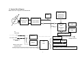
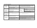
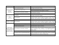
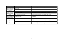
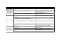
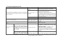
M770E, M770EL
Elliptical CrossTrainer
SERVICE MANUAL
This service manual is for use by Motus trained service providers only.
If you are not a Motus Trained Servicer, you must not attempt to service any Motus product.
Ver 0.1, Oct., 2007
ⓒ Motus Co., Ltd. All Rights reserved.
Unauthorized Reproduction and Distribution Prohibited By Law
Motus Elliptical Cross Trainers M770E and M770EL
Table of Contents
SECTION I TROUBLESHOOTING GUIDE
SECTION II HOW TO REPLACE & REPAIR GUIDE
General
SECTION III HOW TO REPLACE & REPAIR GUIDE,
Electronic PCB
SECTION IV ELECTRONIC PCB, CONNECTOR AND
CABLE OVERVIEW
APPENDIX EXPLODED VIEW
1
Motus Elliptical Cross Trainers M770E and M770EL
SECTION I
TROUBLESHOOTING GUIDE
1.1 System Block Diagram
1.2 Troubleshooting Guide
1.3 Troubleshooting Guide for LCD
2
1.1 System Block Diagram
Note: Dotted line is applied to M770EL/M770E
Operation PCB
Battery
3-Phase
Switching Mode
Rectifier with
Power Supply &
DC Filter
Brake Control
Generator
(Intensity Up/
Intensity Down/
Start/Enter)
Contact HR
PCB
MPU PCB
(Main
Processing
Contact HR/
Wireless HR
PCB
Unit)
AC
100V/220V
Membrane Overlay Key
SMPS-5V
Audio Interface
Headphone Jack
Power ON/OFF
Switch
LCD Power
Adapter
A/D
PCB
Video & Audio Input
(Coaxial, RCA)
LCD Screen
Back-Light
LCD Lamp Inverter PCB
OSD Button PCB for Channel/Volume/Power-on
3
1.2 Troubleshooting Guide
SYMPTOM
No power to
Console
(On M770EL)
LCD TV is normal,
but Dot-LED and
Numeric LED do not
light up
(On M770EL)
Dot-LED and
Numeric LED are
normal, but LCD TV
does not light up or
is blank
PROBABLE CAUSE
Line voltage is not present at equipment.
Check the main circuit breaker and wall outlet voltage at the Facility.
If wall outlet voltage is present, then replace line cord.
Defective MPU Board
Replace Power-on Switch if the output voltage of Power Switch is not
present.
If no voltage, replace Defective SMPS-5V (MPU
Power Supply).
Measure the voltage
If no voltage, verify that CBB3 interconnected
between pin 1 and
with CBB4 cable is plugged into both MPU
pin 4 on CN2.
Board and SMPS-5V. Replace if necessary.
If no voltage, replace MPU PCB.
Refer to 1.3 Troubleshooting Guide for LCD.
Refer to 1.3 Troubleshooting Guide for LCD.
Power-on Switch is damaged.
Defective SMPS-5V (MPU Power Supply)
Defective Wire Harness
Faulty MPU board or Drive board
Console LEDs are
not illuminating
(On M770E)
CORRECTIVE ACTION
Cable connection or loose wire connection
Worn or damaged wire harness
Using a Multi-meter, verify more than 6VDC at pin-7 and pin-8 on CN1.
If voltage is present, replace MPU board. If not, replace Drive board.
Test with substitute MPU board or Drive board. Replace if necessary.
Verify that main cable CN1 is securely plugged into both MPU board and
Drive board. Replace if necessary.
Inspect wire harness. Replace worn or damaged harness.
4
SYMPTOM
Dot-LED or Numeric
LED lights up and
then fails.
(On M770E)
PROBABLE CAUSE
Faulty Battery, Note: Battery is used only for
M770E, self-powered model.
Faulty MPU board or Drive board
Program intensity doesn’t challenge user ability.
Test with substitute Drive board. Replace if necessary.
Verify that main cable CN1 is plugged into both MPU board and Drive
board. Replace if necessary.
Inspect wire harness. Replace worn or damaged harness.
Verify that Battery voltage is greater than 6 volts DC. Replace Battery if
the voltage is lower than 6 volts DC.
Verify that the cable connection at MPU board and Drive board or the
connection between cables at midpoint is plugged in properly. Using a
Multi-meter, verify continuity on all cables. Replace any defective cables.
If cable connection is verified as good, replace the Drive board.
Verify that the cable connection at MPU board and Drive board or the
connection between cables at midpoint is plugged in properly. Using a
Multi-meter, verify continuity on all cables. Replace any defective cables.
Select higher workout intensity.
Drive Belt is worn
Replace Belt.
Drive Belt is excessively loose
Inspect Belt tension. Adjust if necessary.
Verify that the cable connection at MPU board and Drive board or the
connection between cables at midpoint is securely plugged in properly.
Using a Multi-meter, verify continuity on all cables. Replace any
defective cables.
Inspect wire harness. Replace worn or damaged harness.
Verify that workout intensity on Console is increased or decreased by
pressing UP/DOWN button switch. Replace Button Switch or Operation
Button board if there is no change on intensity profile.
Test with substitute MPU board or Drive board. Replace if necessary.
Cable connection or loose wire connection
Worn or damaged wire harness
Faulty Battery
Unit does not Auto
Start
(On M770E)
Cable connection
Faulty Drive board
Unit does not display
SPEED on Console
During exercise
program, pedaling is
insufficiently easy
without providing
adequate resistance.
CORRECTIVE ACTION
Verify that Battery voltage is greater than 6 volts DC. Replace Battery if
the voltage is lower than 6 volts DC.
Test with substitute MPU board. Replace if necessary.
Cable connection
Cable connection or loose wire connection
Worn or damaged wire harness
Faulty Button Switch or Operation Button board
Defective MPU board or Defective Drive board
5
SYMPTOM
Display Console
Keys do not function
and unit does not
respond.
During MANUAL
program, excessive
resistance loading
occurs.
During MANUAL
program, resistance
variance occurs
During exercise
program, loud noise
issuing from unit
PROBABLE CAUSE
Malfunction Overlay, Button Switch or Operation
Button board
Defective MPU board
CORRECTIVE ACTION
Replace Overlay, Button Switch or Operation Button board.
Test with substitute MPU board. Replace if necessary.
Defective MPU board
Test with substitute MPU board. Replace if necessary.
Defective Drive board
Test with substitute Drive board. Replace if necessary.
Worn or damaged wire harness
Inspect wire harness. Replace worn or damaged harness.
Pedaling is too slow
Pedal faster.
Worn bearings
Verify that unit is level on the floor.
Verify that all hardware has been tightened. Apply Loctite where
necessary.
Replace bearings and associated shaft.
Drive Belt is too loose
Inspect Belt. Replace Belt if necessary.
Loose hardware
6
SYMPTOM
Heart rate reading is
abnormally high or is
displayed even when
Chest Strap or
Contact Heart Rate
sensors are not in
use.
PROBABLE CAUSE
CORRECTIVE ACTION
Electromagnetic interference from television sets, cell phones,
refrigerator, or motor driven exercise equipment.
Keep the treadmill away from the probable cause until
the heart rate readings are accurate.
RF energy source from another chest straps.
Keep another chest strap away more than 1 meter until
the heart rate readings are accurate.
Contact Heart Rate cables are pinched at handle bars.
Replace damaged cables.
Chest strap electrodes are not wet enough to sense accurate
heart rate.
The distance between cardio equipments are too close.
Heart rate reading
using wireless chest
strap is erratic or not
displayed
Contact Heart Rate
reading is erratic or
not displayed.
Chest strap electrodes are out of monitoring range.
Chest strap battery is discharged.
Chest strap electrodes are not laid flat or horizontally across
your skin.
Faulty chest strap.
Faulty Wireless HR PCB.
Defective cable or bad connection between Wireless HR PCB
and MPU PCB.
Dampen the Chest strap electrodes with tap waters.
Maintain the distance more than 30 cm.
Make sure the chest strap is within 60cm from Wireless
HR PCB.
Replace chest strap or the battery.
Make sure the chest strap electrodes lies flat and
horizontally across your skin.
Replace chest strap.
Replace Wireless HR PCB.
Check the cable and connection is no problem.
Faulty CHR PCB.
Replace CHR PCB
Dirty handlebar sensors.
Defective cable or bad connection between CHR PCB and MPU
PCB.
User may have an unusual heart rate condition.
Wipe stainless steel sensors with a clean soft cloth.
7
Check the cable and connection is no problem
Let different user grasp sensors to detect any variances.
1.3 Troubleshooting Guide for LCD
Symptom/Condition
PROBABLE CAUSE
Air/cable
correct
Snow and noise are scattering on LCD screen. Any picture is
not found even though channel-up button or channel-down
button is pressed.
setting
is
CORRECTIVE ACTION
not
TV signal source is not
supplied.
75 ohm coaxial cable is bad.
A/D Board is damaged.
Follow the set up procedures in LCD manual.
- Check if the TV signal source is correctly supplied
to A/D PCB from external source.
- Make sure the cable is properly secure.
- If external TV signal is correct, try to connect the
coaxial cable directly to the internal connector in AD
PCB of Console to check whether the internal
cables are wrong or not.
Replace 75 ohm coaxial cable.
Replace A/D Board with new one.
Check if the connection between LCD screen and
A/D Board is tight. In other word, LVDS cable shown
in picture.
LCD screen is uniformly white
Internal cable connection is
loose or disconnected.
Vertical large white-stripe or Vertical stripe block on LCD
screen
Problem with LCD screen
Replace LCD screen
TV mode is not set-up.
1) Whenever you press Volume down button, words
are displayed in following order on the left upper
corner of LCD screen.
“ANALOG”=>”VIDEO”=>”S-VIDEO”=>”TV”
2) Press the button until “TV” is displayed.
3) As soon as “TV” is displayed, snow and noise will
be scattering on LCD screen or any picture will be
captured.
LCD Power Supply has a
problem. Power Supply is
used for supplying 12 VDC
Check if LCD Power supply is normally operated or
LED lamp on Power supply body is turned on.
If LED is off,
LCD screen is dark
or black.
When LCD power is turned on by
pressing TV on/off, “VIDEO”, “S-VIDEO”
or “ANALOG” appears temporarily and
then disappears on the left upper corner
of LCD screen.
When LCD power is turned on by
pressing TV on/off, “VIDEO”, “S-VIDEO”
or “ANALOG” is NOT displayed on the
8
to LCD Overlay
Assembly.
left upper corner of LCD screen.
Bezel
The cable related to LCD
Lamp Inverter is loose in
either side.
TV on/off button is wrong or
stuck.
A/D Board is damaged.
LCD Lamp inverter is
damaged.
LCD Back Light is damaged.
Channels or Volume does not change
No sound
The connector or cable is
bad.
Button to change channels
or volume does not work.
Air/cable setting is not
correct
Faulty headphones
Faulty
headphone
jack
assembly or Audio Interface
Board.
9
z replace Power Adapter.
If LED is on,
z tighten midpoint (LCD Power Supply side)
& endpoint (A/D Board side) connection.
z or make sure the voltage of end point is
DC 12 volt.
Check if the connection is secure.
Replace OSD Button Board.
Replace A/D Board.
Replace LCD Lamp inverter.
Replace LCD screen.
Replace the connector or cable
Replace the button, OSD Button Board or harness
related to it.
Follow the set up procedures in LCD manual.
Replace headphones
Replace Audio Interface Board or headphone jack.
Motus Elliptical Cross Trainers M770E and M770EL
SECTION II
HOW TO REPLACE & REPAIR GUIDE
General
2.1 How to Replace the REAR COVER
2.2 How to Adjust the Drive Belt (or Pulley Belt) Tension
2.3 How to Replace the Drive Belt (or Pulley Belt)
2.4 How to Replace the Generator
2.5 How to Replace the UNIT BEARING – UCF206
2.6 How to Replace the CRANK ASSEMBLY
2.7 How to Disassemble the PEDAL BASE, LOW JOINT CAP or HANDLE
PIVOT JOINT CAP
2.8 How to Replace the NEEDLE BEARINGS inside the PEDAL COUPLER
2.9 How to Replace the OILLESS BUSH inside the COUPLER FRAME
2.10 How to Replace the PEDAL SHAFT
2.11 How to Replace the HANDLE CRANK FRAME
2.12 How to Replace the Heart Rate SENSORS
10
2.1 How to Replace the REAR COVER
The procedures to replace the REAR COVER are commonly applied when the replacements
below are done.
z
How to Adjust the Drive Belt Tension
z
How to Replace the Drive Belt
z
How to Replace the Unit Bearing-UCF206
z
How to Replace the Drive PCB
z
How to Replace the Battery
z
How to Replace the Generator
z
How to Replace the Crank Assembly
11
1) The following tools are required.
Philips Screw Driver, Wrench Sets, Snap Ring Pliers
2) Remove two BUTTON CROSS BOLT (134) securing left REAR COVER-L (133) to right
REAR COVER-R (136).
3) Remove two BUTTON CROSS BOLT (73) and two ALLEN BOLT (135) securing left REAR
COVER-L (133) to the Frame, and then remove left REAR COVER-L (133).
4) Remove two BUTTON CROSS BOLT (73) and two ALLEN BOLT (135) securing right REAR
COVER-R (136) to the Frame, and then remove right REAR COVER-R (136).
5) Remove six BUTTON CROSS BOLT (73) and then lift REAR COVER-C (139) up.
6) Replace the specific part while referring to “How to …” if required.
7) Install the REAR COVER-C, REAR COVER-R and REAR COVER-L in reverse order.
12
2.2 How to Adjust the Drive Belt (or Pulley Belt) Tension
1) Loosen two HEX LOCK NUTs (11) a little
using 17mm spanner.
2) To increase the tension, turn HEX NUT
(21) clockwise with a 19mm spanner while
holding H/S HEX BOLT (12) with another
19mm spanner. Initial tension is set to 190
Hz. To decrease the tension, turn HEX NUT
(21) counterclockwise.
3) Make sure that PULLEY BELT does not
slip and then install the REAR COVER-C,
REAR COVER-R and REAR COVER-L in
reverse order.
2.3 How to Replace the Drive Belt (or Pulley Belt)
1) Loosen two HEX LOCK NUTs
(11) a little using 17mm spanner.
2) To loosen the PULLEY BELT
(22),
turn
HEX
counterclockwise
with
NUT
a
(21)
19mm
spanner while holding H/S HEX
BOLT (12) with another 19mm
spanner. See “2.2 How to Adjust the
Drive Belt (or Pulley Belt) Tension”
3) Derail the slackened PULLEY
BELT (22) from the PULLEY (19).
4) Remove CAP HEX NUT (163) and PLANE WASHER (49) using 24 mm spanner.
5) Pull COUPLER FRAME (42) out of CRANK ASS’Y-230 (39) by lifting it off.
6) Remove H/S HEX BOLT (41) and HEX LOCK NUT (13) using 21 mm Spanner and then slide
CRANK ASS’Y-230 (39) off the Shaft of the Pulley (19).
7) Remove SQUARE KEY (161) from the Shaft.
8) Remove four H/S HEX BOLTs (25) using 17 mm spanner and then slide the BEARINGUCF206 (23) off the Frame and Shaft of the Pulley (19).
9) To remove the CRANK ASS’Y-230 and BEARING-UCF206 in opposite side, repeat the same
13
procedures as 4) thru 8).
10) Remove the PULLEY (19) combined with the Shaft by taking it out toward the front of the
Machine.
11) Remove the PULLEY BELT (22).
12) Install the new PULLETY BELT (22) in reverse order.
13) If needed, adjust the Pulley Belt Tension. See “2.2 How to Adjust the Drive Belt (or Pulley
Belt) Tension”
2.4 How to Replace the Generator
1)
Disconnect
two
cables
from
the
GENERATOR.
2) Loosen two HEX LOCK NUTs (11) a little
using 17mm spanner. See “2.3 How to
Replace the Drive Belt”
3) To loosen the PULLEY BELT (22), turn
HEX NUT (21) counterclockwise with a
19mm spanner while holding H/S HEX BOLT
(12) with another 19mm spanner. See “2.3
How to Replace the Drive Belt”
4) Derail the slackened PULLEY BELT (22) from the PULLEY (19). See “2.3 How to Replace
the Drive Belt”
5) Remove ALLEN BOLT (15), HEX LOCK NUT (16) and PLANE WASHER (17) securing the
GENERATOR (14) to the GENERATOR FRAME (9) by using 4mm wrench and 10 mm spanner.
6) Remove the GENERATOR (14) from the GENERATOR FRAME (9).
7) Install new the GENERATOR (14) in reverse order.
8) If needed, adjust the Pulley Belt Tension. See “2.2 How to Adjust the Drive Belt (or Pulley
Belt) Tension”
14
2.5 How to Replace the UNIT BEARING – UCF206
The procedure to replace the
Bearing is same on both right
side and left side.
1) Loosen two HEX LOCK
NUTs (11) a little using 17mm
spanner.
2) To loosen the PULLEY BELT
(22),
turn
HEX
NUT
(21)
counterclockwise with a 19mm
spanner while holding H/S HEX
BOLT (12) with another 19mm
spanner.
3) Derail the slackened PULLEY BELT (22) from the PULLEY (19).
4) Remove CAP HEX NUT (163) and PLANE WASHER (49) using 24 mm spanner.
5) Pull COUPLER FRAME (42) out of CRANK ASS’Y-230 (39) by lifting it off.
6) Remove H/S HEX BOLT (41) and HEX LOCK NUT (13) using 21 mm spanner and then slide
CRANK ASS’Y-230 (39) off the Shaft (18) of the Pulley (19).
7) Remove SQUARE KEY (161) from the Shaft.
8) Remove four H/S HEX BOLTs (25) using 17 mm spanner and then slide the BEARINGUCF206 (23) off the SHAFT ASS’Y(18).
9) Install new BEARING-UCF206 (23) in reverse order.
10) If needed, adjust the Pulley Belt Tension. See “2.2 How to Adjust the Drive Belt (or Pulley
Belt) Tension”
15
2.6 How to Replace the CRANK ASSEMBLY
1) Loosen two HEX LOCK NUTs (11) a
little using 17mm spanner.
2) To loosen the PULLEY BELT (22), turn
HEX NUT (21) counterclockwise with a
19mm spanner while holding H/S HEX
BOLT (12) with another 19mm spanner.
3) Derail the slackened PULLEY BELT
(22) from the PULLEY (19).
4) Remove CAP HEX NUT (163) and
PLANE WASHER (49) using 24 mm
spanner.
5) Pull COUPLER FRAME (42) out of CRANK ASS’Y-230 (39) by lifting it off.
6) Remove H/S HEX BOLT (41) and HEX LOCK NUT (13) using 21 mm spanner and then slide
CRANK ASS’Y-230 (39) off the Shaft (18) of the Pulley (19).
7) Install new CRANK ASS’Y-230 (39) in reverse order.
16
2.7 How to Disassemble the PEDAL BASE, LOW JOINT CAP or HANDLE
PIVOT JOINT CAP
2.7.1 How to Disassemble the PEDAL BASE
1) Remove the plastic PEDAL BASE (54) by loosening four PILLOW CROSS BOLTs (57).
2) Reassemble the parts in reverse order.
2.7.2 How to Disassemble the LOW JOINT CAP
1) Remove LOW JOINT CAP-T (144) by loosening four BUTTON CROSS BOLTs (146) using
Phillips driver.
2) Remove LOW JOINT CAP-B (145) by loosening four BUTTON CROSS BOLTs (146) using
Phillips driver.
3) Reassemble the parts in reverse order.
2.7.3 How to Disassemble the HANDLE PIVOT JOINT CAP
1) Remove HANDLE PIVOT JOINT CAP BADGE (143) by using sharp-tip screw driver to lift it
17
out of the engaged HANDLE PIVOT JOINT CAP-T (141) and HANDLE PIVOT JOINT CAP-B
(142).
2) Remove the HANDLE PIVOT JOINT CAP-T (141) and HANDLE PIVOT JOINT CAP-B (142)
from HANDLE CRANK FRAME (94) by opening these two parts while pushing the edge of the
engaged HANDLE PIVOT JOINT CAP-T (141) and HANDLE PIVOT JOINT CAP-B (142).
3) Reassemble the parts in reverse order.
2.8 How to Replace the NEEDLE BEARINGS inside the PEDAL COUPLER
(Or How to Replace the OILLESS BUSH inside the PEDAL COUPLER with
NEEDLE BEARINGS)
1) Disassemble the plastic PEDAL BASE. See “2.7.1 How to Disassemble PEDAL BASE”
2) Loosen the upper PEDAL SHAFT
(52) and the upper HEX LOCK NUT
(13) a little by using 17 mm spanner
and 19 mm spanner each. Slight
loosening
through
this
process
makes it easy to remove lower
PEDAL SHAFT (52) securing the
PEDAL
COUPLER
(58)
to
the
PEDAL FRAME.
3) Remove the lower PEDAL SHAFT
(52) and the lower HEX LOCK NUT
(13) by using 17 mm spanner and 19 mm spanner each. Two PEDAL REAR SHAFT BUSHes
(62) are also removed.
4) Remove the SNAP RING (61) securing the PEDAL COUPLER (58) to the COUPLER FRAME
(42) by using snap ring pliers.
5) Remove the PEDAL FRONT SHAFT (59) by pulling out it. Two PEDAL FRONT SHAFT
BUSHes (60) are also removed.
6) Take out the PEDAL COUPLER (58), which is inside the pipe “COUPLER FRAME (42)”, from
the front side of the pipe.
7) Remove the NEEDLE BEARINGS (53, or oil-less bush before update) which are inside the
both end of the PEDAL COUPLER (58).
8) Install new NEEDLE BEARINGS in reverse order.
18
2.9 How to Replace the OILLESS BUSH inside the COUPLER FRAME
1) Disassemble the plastic PEDAL BASE. See “2.7.1 How to Disassemble PEDAL BASE”
2) Loosen the upper PEDAL SHAFT (52) and the upper HEX LOCK NUT (13) a little by using
17 mm spanner and 19 mm spanner each. Slight loosening through this process makes it easy
to remove lower PEDAL SHAFT (52) securing the PEDAL COUPLER (58) to the PEDAL
FRAME.
3) Remove the lower PEDAL SHAFT (52) and the lower HEX LOCK NUT (13) by using 17 mm
spanner and 19 mm spanner each. Two PEDAL REAR SHAFT BUSHes (62) are also removed.
4) Remove the SNAP RING (61) securing the PEDAL COUPLER (58) to the COUPLER FRAME
(42) by using snap ring pliers.
5) Remove the PEDAL FRONT SHAFT (59) by pulling out it. Two PEDAL FRONT SHAFT
BUSHes (60) are also removed.
6) Take out the PEDAL COUPLER (58), which is inside the pipe “COUPLER FRAME (42)”, from
the front side of the pipe.
7) Remove the PEDAL FRAME (51) from HANDLE CRANK FRAME (94) by loosening the
upper PEDAL SHAFT (52) and the upper HEX LOCK NUT (13) by using 17 mm spanner and 19
mm spanner each.
8) Remove the COUPLER FRONT
SHAFT (43) from the HANDLE
CRANK FRAME (94). Be careful
the COUPLER FRAME (42) can be
fallen out of the HANDLE CRANK
FRAME (94).
9) Remove the CAP HEX NUT
(163) from the COUPLER REAR
HOUSING (47) by using 24 mm
spanner.
10)
Remove
the
COUPLER
FRAME (42) from the COUPLER REAR HOUSING (47) by lifting it up.
11) Remove the OILLESS BUSH (44, HB203040) or the OILLESS BUSH (53, HB1420).
12) Apply a bearing grease to the outer surface of the OILLES BUSH and then install the
OILLESS BUSH in reverse order.
19
2.10 How to Replace the PEDAL SHAFT
1)
Disassemble
the
plastic
PEDAL BASE. See “2.7.1 How to
Disassemble PEDAL BASE”
2) Loosen the upper PEDAL
SHAFT (52) and the upper HEX
LOCK NUT (13) a little by using
17 mm spanner and 19 mm
spanner each. Slight loosening
through this process makes it
easy to remove lower PEDAL
SHAFT (52) securing the PEDAL
COUPLER (58) to the PEDAL
FRAME.
3) Remove the lower PEDAL SHAFT (52) and the lower HEX LOCK NUT (13) by using 17 mm
spanner and 19 mm spanner each. Two PEDAL REAR SHAFT BUSHes (62) are also removed.
4) Remove the upper PEDAL SHAFT (52) and the upper HEX LOCK NUT (13) by using 17 mm
spanner and 19 mm spanner each.
5) Install new PEDAL SHAFT (52) in reverse order.
2.11 How to Replace the HANDLE CRANK FRAME
1) Remove SNAP RING (61) by using snap ring
pliers.
2) Remove the PEDAL FRONT SHAFT (59)
from the HANDLE CRANK FRAME (94). PEDAL
FRONT SHAFT BUSH (60) is also removed.
3) Remove the COUPLER FRONT SHAFT (43)
from the HANDLE CRANK FRAME (94). Be
careful the COUPLER FRAME (42) can be
fallen out of the HANDLE CRANK FRAME (94).
4) Remove HANDLE BAR-L (107) by loosening
four ALLEN BUTTON BOLTs (108) using 6 mm
Wrench.
5) Disconnect the interconnected Heart Rate Cable(C) under HANDLE BAR-L (107).
6) Remove SNAP RING (98) by using snap ring pliers.
20
7) Remove the HANDLE CRANK FRAME (94) from the AXIS toward the longitudinal direction of
the AXIS (960) and keep the PLANE WAHSER (95) in position as shown.
8) Install new HANDLE CRANK FRAME (94) in reverse order.
.
2.12 How to Replace the Heart Rate SENSORS
- Pending -
21
Motus Elliptical Cross Trainers M770E and M770EL
SECTION III
HOW TO REPLACE & REPAIR GUIDE
Electronic PCB
3.1 How to Replace the LCD Screen in Model M770EL
3.2 How to Replace the A/D Board in Model M770EL
3.3 How to Replace the MPU Board in Model MM770EL
3.4 How to Replace the MPU Board in Model M770E
3.5 How to Replace the OPERATION BUTTON Board
3.6 How to Replace the LAMP INVERTER Board in Model M770E
3.7 How to Replace the Program BUTTON Board, OSD BUTTON Board &
AUDIO INTERFACE & DOWNLOAD Board in Model M770EL
3.8 How to Replace the DRIVE Board.
3.9 How to Replace the BATTERY for M770E
3.10 How to Replace the SMPS-5V (or MPU POWER SUPPLY)
3.11 How to Replace the LCD POWER ADAPTER.
22
3.1 How to Replace the LCD Screen in Model M770EL
Fig 3a CONSOLE & POST
23
Fig 3b CONSOLE
24
Do the steps below while referring to Fig 3a CONSOLE & POST, Fig 3b CONSOLE and Section
4 ELECTRONIC PCB, CONNECTOR AND CABLE OVERVIEW.
1) Turn off the unit power at the switch and then unplug the line cord at wall outlet.
2) Remove the DISPLAY REAR COVER (74) from the DISPLAY PANEL BOTTM (72) by
unscrewing four screws (75).
3) Remove the DISPLAY PANEL TOP (63) from the DISPLAY PANEL BOTTOM (72) by
unscrewing four screws (73) securing the DISPLAY PANEL TOP (63).
4) Disconnect all the cables from the DISPLAY PANEL TOP (63) and then place the DISPLAY
PANEL TOP (63) on the flat and clean surface so that the LCD screen faces downward.
5) Disconnect one end of the OSD BUTTON CABLE (CB21) from the side of A/D BOARD (8).
The OSD BUTTON CABLE (CB21) is connected in between the A/D BOARD (8) and OSD
BOARD (11).
6) Remove the LCD PANEL BRACKET (3) from the DISPLAY PANEL TOP (1) by unscrewing
six screws (7).
7) Disconnect one end of the LVDS CABLE (CB31) from the side of the LCD PANEL (2). The
other end of the LVDS CABLE (CB31) doesn’t need to be disconnected from the A/D BOARD
(8).
8) Disconnect the LAMP INVERTER CABLE (CB32) from the LAMP INVERTER (6).
9) Place the LCD BRACKET (3) upside down so that the LCD PANEL (2) faces upward.
10) Remove the LCD PANEL (2) by unscrewing four screws (4) securing the LCD PANEL (2) to
the LCD BRACKET.
11) Install new LCD PANEL (2) in reverse order.
25
3.2 How to Replace the A/D Board in Model M770EL
Do the steps below while referring to Fig 3a CONSOLE & POST, Fig 3b CONSOLE and Section
4 ELECTRONIC PCB, CONNECTOR AND CABLE OVERVIEW.
1) Turn off the unit power at the switch and then unplug the line cord at wall outlet.
2) Remove the DISPLAY REAR COVER (74) from the DISPLAY PANEL BOTTM (73) by
unscrewing four screws (75).
3) Remove four screws (73) securing the DISPLAY PANEL TOP (63) to the DISPLAY PANEL
BOTTOM (72).
4) Lift off the DISPLAY PANEL TOP (63) while disconnecting all the cables from the DISPLAY
PANEL TOP (63) and then place the DISPLAY PANEL TOP (63) on the flat and clean surface
so that the LCD screen faces downward.
5) Disconnect all the cables from the A/D BOARD (8).
6) Remove the A/D BOARD (8) from the LCD PANEL BRACKET (3) by unscrewing four screws
(7).
7) Install new A/D BOARD (8) in reverse order.
26
3.3 How to Replace the MPU Board in Model M770EL
Do the steps below while referring to Fig 3a CONSOLE & POST, Fig 3b CONSOLE and Section
4 ELECTRONIC PCB, CONNECTOR AND CABLE OVERVIEW.
1) Turn off the unit power at the switch and then unplug the line cord at wall outlet.
2) Remove the DISPLAY REAR COVER (74) from the DISPLAY PANEL BOTTM (72) by
unscrewing four screws (75).
3) Remove four screws (73) securing the DISPLAY PANEL TOP (63) to the DISPLAY PANEL
BOTTOM (72).
4) Lift off the DISPLAY PANEL TOP (63) while disconnecting all the cables from the DISPLAY
PANEL TOP (63) and then place the DISPLAY PANEL TOP (631) on the flat and clean surface
so that the LCD screen faces downward.
5) Disconnect all the cables from the MPU BOARD_FRONT (13).
6) Remove three screws (7) securing the MPU BOARD_BACK (15) to the MPU
BOARD_FRONT (13).
7) Carefully lift the MPU BOARD_BACK (15) off the MPU BOARD_FRONT (13) so that the pins
on the both edges of the MPU BOARD_FRONT are not damaged or bended.
8) Remove four screws (12) and three HEXGON SPACER (14) securing the MPU
BOARD_FRONT (13) to the DISPLAY PANEL_TOP (11).
9) Lift off the MPU BOARD_FRONT (13)
10) Install new MPU BOARD_FRONT or MPU BOARD_BACK in reverse order.
27
3.4 How to Replace the MPU Board in Model M770E
Do the steps below while referring to Fig 3a CONSOLE & POST, Fig 3b CONSOLE and Section
4 ELECTRONIC PCB, CONNECTOR AND CABLE OVERVIEW.
1) Remove the DISPLAY REAR COVER (74) from the DISPLAY PANEL BOTTM (72) by
unscrewing four screws (75).
2) Remove four screws (73) securing the DISPLAY PANEL TOP (63) to the DISPLAY PANEL
BOTTOM (72).
3) Lift off the DISPLAY PANEL TOP (63) while disconnecting all the cables from the DISPLAY
PANEL TOP (63) and then place the DISPLAY PANEL TOP (63) on the flat and clean surface
so that it faces downward.
4) Disconnect all the cables including Ribbon cable from the MPU BOARD (27).
5) Remove eight screws (12) securing the MPU BOARD (27) to the DISPLAY PANEL TOP (1).
6) Lift off the MPU BOARD (27) out of the DISPLAY PANEL TOP (1).
7) Install new MPU BOARD (27) in reverse order.
28
3.5 How to Replace the OPERATION BUTTON Board
Do the steps below while referring to Fig 3a CONSOLE & POST, Fig 3b CONSOLE and Section
4 ELECTRONIC PCB, CONNECTOR AND CABLE OVERVIEW.
1) If the machine is M770EL with LCD monitor, turn off the unit power at the switch and then
unplug the line cord at wall outlet.
2) Remove the DISPLAY REAR COVER (74) from the DISPLAY PANEL BOTTM (72) by
unscrewing four screws (75).
2) Remove four screws (73) securing the DISPLAY PANEL TOP (63) to the DISPLAY PANEL
BOTTOM (72).
3) Lift off the DISPLAY PANEL TOP (63) while disconnecting all the cables from the DISPLAY
PANEL TOP (63) and then place the DISPLAY PANEL TOP (63) on the flat and clean surface
so that it faces downward.
4) Disconnect all of cables from the OPERATION BUTTON BOARD (21).
5) Remove the OPERATION BUTTON BOARD from the DISPLAY BUTTON CONTROL (20) by
unscrewing five screws (12).
6) Install new OPERATION BUTTON BOARD (21) in reverse order.
29
3.6 How to Replace the LAMP INVERTER Board in Model M770EL
Do the steps below while referring to Fig 3a CONSOLE & POST, Fig 3b CONSOLE and Section
4 ELECTRONIC PCB, CONNECTOR AND CABLE OVERVIEW.
1) Turn off the unit power at the switch and then unplug the line cord at wall outlet.
2) Remove the DISPLAY REAR COVER (74) from the DISPLAY PANEL BOTTM (72) by
unscrewing four screws (75).
3) Remove four screws (73) securing the DISPLAY PANEL TOP (63) to the DISPLAY PANEL
BOTTOM (72).
4) Lift off the DISPLAY PANEL TOP (63) while disconnecting all the cables from the DISPLAY
PANEL TOP (63) and then place the DISPLAY PANEL TOP (63) on the flat and clean surface
so that the LCD screen faces downward.
5) On the side of the LAMP INVERTER board (6), disconnect the LAMP INVERTER CABLE
(CB32) which is connected between the LAMP INVERTER board (6) and A/D BOARD (8).
6) Disconnect all the cables between the LAMP INVERTER board (6) and LCD panel (21).
7) Remove the LAMP INVERTER board (6) from the LCD PANEL BRACKET (3) by unscrewing
two screws (12).
8) Install new LAMP INVERTER board in reverse order.
30
3.7 How to Replace the Program BUTTON Board, OSD BUTTON Board &
AUDIO INTERFACE & DOWNLOAD Board in Model M770EL
Do the steps below while referring to Fig 3a CONSOLE & POST, Fig 3b CONSOLE and Section
4 ELECTRONIC PCB, CONNECTOR AND CABLE OVERVIEW.
1) Turn off the unit power at the switch and then unplug the line cord at wall outlet.
2) Remove the DISPLAY REAR COVER (74) from the DISPLAY PANEL BOTTM (72) by
unscrewing four screws (75).
3) Remove four screws (73) securing the DISPLAY PANEL TOP (63) to the DISPLAY PANEL
BOTTOM (72).
4) Lift off the DISPLAY PANEL TOP (63) while disconnecting all the cables from the DISPLAY
PANEL TOP (63) and then place the DISPLAY PANEL TOP (63) on the flat and clean surface
so that the LCD screen faces downward.
Program BUTTON Board
5) On the side of the PROGRAM BUTTON Board (10), disconnect the PROGRAM BUTTON
CABLE (CB19) which is connected between the MPU_BOARD_FRONT (13) and PROGRAM
BUTTON Board (10)
6) Remove the PROGRAM BUTTON Board (10) from the DISPLAY BUTTON_LCD (9) by
unscrewing three screws (12).
7) Install new PROGRAM BUTTON Board (10) in reverse order.
OSD BUTTON Board
5) On the side of the OSD BUTTON Board (11), disconnect the OSD BUTTON CABLE (CB21)
which is connected between the A/D Board (8) and OSD BUTTON Board (11),
6) Remove the OSD BUTTON Board (11) from the DISPLAY BUTTON_LCD (9) by unscrewing
three screws (12).
7) Install new OSD BUTTON Board (11) in reverse order.
AUDIO INTERFACE & DOWNLOAD Board
5) Disconnect the AUDIO OUT CABLE (CB21) and DOWNLOAD CABLE (CB10) from the side
of the AUDIO INTERFACE & DOWNLOAD Board (24).
6) Remove the AUDIO INTERFACE & DOWNLOAD Board (24) from the DISPLAY
BUTTON_LCD (9) by unscrewing three screws (12).
31
7) Install new AUDIO INTERFACE & DOWNLOAD Board (24) in reverse order.
32
3.8 How to Replace the DRIVE Board
1) Disconnect three cables from the DRIVE PCB
(31).
2) Remove the DRIVE PCB (31) by loosening four
BUTTON CROSS BOLTs (32).
3) Install new DRIVE PCB (31) in reverse order.
Make sure three cables are firmly connected to the
DRIVE PCB (31).
3.9 How to Replace the BATTERY for
M770E
1) Disconnect two cables from the BATTERY(33).
2) Remove the BATTERY (33) by loosening two BUTTON CROSS BOLTs (35).
3) Install new BATTERY (33) in reverse order.
Make sure two cables are firmly connected to the BATTERY (33).
33
3.10 How to Replace the SMPS-5V (or MPU POWER SUPPLY) in M770EL
Applicable to old version before Nov., 2007
1) Turn off the unit power at switch and then unplug the power cord at the wall outlet.
2) Remove the Badge (143) from the Handle Pivot Joint Cap (141, 142).
3) Remove the Handle Pivot Joint Cap (141, 142) by separating engaged Handle Pivot Joint
Cap (141, 142) into two pieces.
4) Lift up the Bottle Holder (130) and Accessory Holder (129) from the Handle Pivot Cover (127).
5) Remove four Button Cross Bolts (128) securing the Handle Pivot Cover (127) and then
remove the Handle Pivot Cover (127) from the unit.
6) Remove the Front Stabilizer Cover (123, 125) from the unit by pulling them out by hand or
using a rubber hammer.
7) Remove two Button Screws (75) securing the Front Stabilizer Cover-C (122) and remove the
Front Stabilizer Cover-C (122) from the unit while disconnecting all of cables.
8) Remove six Button Screws (75) securing the Front Bottom Cover (121) and remove the Front
Bottom Cover (121)
9) Remove ten Button Screws (75) securing the Front Outer Cover (120) and remove the Front
Outer Cover (120) from the unit.
34
10) Disconnect all of cables from the SMPS (116).
11) Remove four Screws (117) securing the SMPS (116) to the SMPS-BRK (113).
12) Install new SMPS (116) in reverse order.
35
3.11 How to Replace the LCD POWER ADAPTER (or LCD Power Supply)
Applicable to old version before Nov., 2007
1) Turn off the unit power at switch and then unplug the power cord at the wall outlet.
2) Remove the Badge (143) from the Handle Pivot Joint Cap (141, 142).
3) Remove the Handle Pivot Joint Cap (141, 142) by separating engaged Handle Pivot Joint
Cap (141, 142) into two pieces.
4) Lift up the Bottle Holder (130) and Accessory Holder (129) from the Handle Pivot Cover (127).
5) Remove four Button Cross Bolts (128) securing the Handle Pivot Cover (127) and then
remove the Handle Pivot Cover (127) from the unit.
6) Remove the Front Stabilizer Cover (123, 125) from the unit by pulling them out by hand or
using a rubber hammer.
7) Remove two Button Screws (75) securing the Front Stabilizer Cover-C (122) and remove the
Front Stabilizer Cover-C (122) from the unit while disconnecting all of cables.
8) Remove six Button Screws (75) securing the Front Bottom Cover (121) and remove the Front
Bottom Cover (121)
9) Remove ten Button Screws (75) securing the Front Outer Cover (120) and remove the Front
Outer Cover (120) from the unit.
36
10) Remove twelve Button Screws (75) securing the Front Inner Cover (118,119) and then
remove the Front Inner Cover (118,119) from the unit.
11) Disconnect all of cables from the LCD Power Supply (15) and SMPS (116).
12) Remove four Button Cross Bolts (115) securing the SMPS-BRK (113) and then remove the
SMPS-BRK (113) from the unit.
13) Remove four Button Cross Bolts (35) securing LCD Power Supply BRK (114) to SMPS-BRK
(113) and then remove LCD Power Supply (115).
14) Install new LCD Power Supply (115) in reverse order.
37
Motus Elliptical Cross Trainers M770E and M770EL
SECTION IV
ELECTRONIC PCB, CONNECTOR AND
CABLE OVERVIEW
4.1 Cable Connection Block Diagram
4.2 Electronic PCB, Connector and Pin Description
4.3 Cables & Connectors
4.4 Cable Diagram
38
4.1 Cable Connection Block Diagram
1) MPU PCB on M770EL
MPU_FRONT (Display), MPU_BACK (MAIN)
39
2) MPU PCB on M770E
40
3) A/D BOARD on M770EL
41
4) POWER BOARD
4-1) M770EL (DRIVE Board, SMPS-5V, LCD POWER ADAPTER)
4-2) M770E (DRIVE Board)
42
4.2 Electronic PCB, Connector and Pin Description
1) MPU PCB, M770EL
1-1) MPU_BACK (or MPU_Main)
Connector
Location
Pin
Pin Name
CN 1 :
1
NC
Main Cable
2
GND
3
NC
No Connection
4
NC
No Connection
5
PWM
6
E/P
7
GND
8
NC
CN 2 :
1
VCC
Not used
Reserved Port
2
TXD_PC
Not used
(RS-232)
3
RXD_PC
Not used
4
GND
Not used
CN 3 :
1
VCC
+5V
Serial Port (RS-232)
2
TXD_PC
Transmit data ( M770E Æ PC)
3
RXD_PC
Receive data( PC Æ M770E )
4
GND
43
Functional Description
No Connection
Ground
PWM Output
Encoder Pulse Input
Ground
No Connection
Ground
Connector
Location
Pin
Pin Name
CN 4, CN 13 : Contact
1
Signal 1
Sensor Plate signal 1
Heart Rate Sensor
2
Signal 2
Sensor Plate signal 2
CN 5 : Step Sensor
1
VCC
+5V
Not used
2
STEP
Not used
3
GND
Ground
1
VCC
VCC, Not used
2
HR_TCH
3
VCC
VCC, Not used
4
GND
Ground, Not used
1
T_VCC
VCC, Not used
2
T_GND
Ground, Not used
3
T_VCC
VCC, Not used
CN 8, CN 14 : Contact
1
Signal 1
Sensor Plate signal 1
Heart Rate Sensor
2
Signal 2
Sensor Plate signal 2
CN 9 :
1
T232/PDO
Program Data Output
Program Download
2
VCC
+5V
3
SCK
Serial Clock
4
R232/PDI
5
RESET
6
GND
Pin
Pin Name
CN 10 :
1
Signal
Heart Rate Signal
2
VCC
+5V for Heart Rate
3
GND
Ground for Heart Rate
CN 6 : Not used
CN 7 : Not used
Connector
Location
44
Functional Description
Not used
Program Data Input
Receive data
Ground
Functional Description
Signal from Heart Rate Board
Connector
Location
Pin
Pin Name
CN 11 : Overlay button
1
B4
Data In 4
(or Membrane)
2
B3
Data In 3
3
B2
Data In 2
4
B1
Data In 1
5
Q6
Data Output 6
6
Q5
Data Output 5
7
Q4
Data Output 4
8
Q3
Data Output 3
9
Q2
Data Output 2
10
Q1
Data Output 1
CN 12 :
1
GND
Ground
Operation Button
2
GND
Ground
3
B4
Key Data Input 4
4
B3
Key Data Input 3
5
B2
Key Data Input 2
6
B1
Key Data Input 1
7
Q6
Key Scan Output 6
8
VCC
Vcc
CN 15 :
1
VCC
VCC
Main Power
2
GND
Ground
CN 16 :
1
Q1
Data Output 1
Program Button
2
Q2
Data Output 2
3
Q3
Data Output 3
4
Q4
Data Output 4
5
B4
Data In 4
45
Functional Description
Connector
Location
Pin
Pin Name
J1 : Display Interface
1
VCC
Vcc
Header 1
2
VCC
Vcc
3
VCC
Vcc
4
CS0
Chip Select 0
5
CS1
Chip Select 1
6
CS3
Chip Select 3
7
CS4
Chip Select 4
8
CS5
Chip Select 5
9
CS6
Chip Select 6
10
CS8
Chip Select 8
11
GND
Ground
12
GND
Ground
13
GND
Ground
J2 : Display Interface
1
AD0
Address/Data 0
Header 2
2
AD1
Address/Data 1
3
AD2
Address/Data 2
4
AD3
Address/Data 3
5
AD4
Address/Data 4
6
AD5
Address/Data 5
7
AD6
Address/Data 6
8
AD7
Address/Data 7
9
D_CLK
10
D_LE
11
D_RED
12
D_GR
46
Functional Description
Dot Display Clock
Dot Display Latch Enable
Dot Display RED Data
Dot Display GREEN Data
1-2) MPU_FRONT ( or MPU_DISPLAY)
Connector
Location
Pin
Pin Name
J1 : MPU Interface
1
VCC
Vcc
Header 1
2
VCC
Vcc
3
VCC
Vcc
4
CS0
Chip Select 0
5
CS1
Chip Select 1
6
CS3
Chip Select 3
7
CS4
Chip Select 4
8
CS5
Chip Select 5
9
CS6
Chip Select 6
10
CS8
Chip Select 8
11
GND
Ground
12
GND
Ground
13
GND
Ground
J2 : MPU Interface
1
AD0
Address/Data 0
Header 2
2
AD1
Address/Data 1
3
AD2
Address/Data 2
4
AD3
Address/Data 3
5
AD4
Address/Data 4
6
AD5
Address/Data 5
7
AD6
Address/Data 6
8
AD7
Address/Data 7
9
D_CLK
10
D_LE
11
D_RED
12
D_GR
47
Functional Description
Dot Display Clock
Dot Display Latch Enable
Dot Display RED Data
Dot Display GREEN Data
2) MPU PCB, M770E
Connector
Location
Pin
Pin Name
CN 1 :
1
VCC
Drive VCC 7.5V
Main Cable
2
GND
Ground
3
VCC
Drive VCC 7.5V
4
NC
No Connection
5
PWM
6
E/P
7
GND
Ground
8
VCC
Drive VCC 7.5V
48
Functional Description
PWM Output
Encoder Pulse Input
Connector
Location
Pin
Pin Name
CN 2 :
1
VCC
Not used
Reserved Port
2
TXD_PC
Not used
(RS-232)
3
RXD_PC
Not used
4
GND
Not used
CN 3 :
1
VCC
Battery VCC 6V
Battery Power
2
GND
Ground
CN 4 :
1
VCC
+5V, Not used
Serial Port (RS-232),
2
TXD_PC
Transmit data ( M770E Æ PC), Not used
Not used
3
RXD_PC
Receive data( PC Æ M770E ), Not used
4
GND
CN 5, CN 15 : Contact
1
Signal 1
Sensor Plate signal 1
Heart Rate Sensor
2
Signal 2
Sensor Plate signal 2
CN 6 :
1
VCC
Not used
Not used
2
HR_TCH
Not used
3
VCC
Not used
4
GND
Not used
CN 7 :
1
T_VCC
Not used
Not used
2
T_GND
Not used
3
T_VCC
Not used
CN 8, CN 16 : Contact
1
Signal 1
Sensor Plate signal 1
Heart Rate Sensor
2
Signal 2
Sensor Plate signal 2
49
Functional Description
Ground, Not used
Connector
Location
Pin
Pin Name
CN 9 :
1
T232/PDO
Program Download
2
VCC
+5V
3
SCK
Serial Clock
4
R232/PDI
5
RESET
6
GND
Ground
CN 10 :
1
Signal
Signal from Heart Rate Board
Heart Rate Signal
2
VCC
Heart Rate +5V
3
GND
Heart Rate Ground
CN 11 : Overlay
1
B4
Data In 4
(or Membrane)
2
B3
Data In 3
3
B2
Data In 2
4
B1
Data In 1
5
Q6
Data Output 6
6
Q5
Data Output 5
7
Q4
Data Output 4
8
Q3
Data Output 3
9
Q2
Data Output 2
10
Q1
Data Output 1
CN 12 :
1
GND
Ground
Operation Button
2
GND
Ground
3
B4
Key Data Input 4
4
B3
Key Data Input 3
5
B2
Key Data Input 2
6
B1
Key Data Input 1
7
Q6
Key Scan Output 6
8
VCC
50
Functional Description
Program Data Output
Program Data Input
Receive data
Vcc
Connector
Location
Pin
Pin Name
CN 13 :
1
VCC
Not used
Step Sensor
2
STEP
Not used
3
GND
Not used
CN 14 :
1
B+VCC
Not used
Test Power
2
GND
Not used
3
VCC
Not used
51
Functional Description
3) Operation Button Board
Connector
Location
Pin
Pin Name
Functional Description
CN 1 :
1
GND
Ground
Operation Button
2
GND
Ground
(Start/Stop, Intensity
3
START/STOP
Start/Stop Key
Up, Intensity Down)
4
UP
Level UP Key
5
DOWN
Level Down Key
6
ENTER
ENTER Key
7
SCAN
Signal Scan
8
VCC
Pin
Pin Name
CN 1 :
1
Q1
Data Output 1
Program Button
2
Q2
Data Output 2
3
Q3
Data Output 3
4
Q4
Data Output 4
5
B4
Data In 4
VCC
4) Program Button Board
Connector
Location
52
Functional Description
5) A/D Board
Connector
CN 1 : Audio Out
Location
Pin
Pin Name
1
Audio Left
2
GND
3
Audio Right
4
GND
Functional Description
Audio Left
Ground
Audio Right
Ground
CN 2 : SVIDEO
S-VIDEO Input
CN 3 : DC In
DC 12V/3.5A Input
CN 5 : Video In
Video Input (Yellow)
CN 8 : Audio In
Audio Input (Red)
CN 9 : Audio In
Audio Input (White)
53
Connector
Location
Pin
Pin Name
Functional Description
CN 10 :
1
VCC
DC 12V/3.5A Vcc
LAMP Inverter
2
VCC
DC 12V/3.5A Vcc
Control
3
VCC
DC 12V/3.5A Vcc
4
GND
Ground
5
GND
Ground
6
GND
Ground
7
DIM CTRL
8
On/Off
Back Light On/Off Control
CN 11 :
1
LED1
LDE Lamp
OSD Key In
2
KEY1
Key Input
3
KEY2
Key Input
4
5V
5
GND
Ground
6
LED2
LED Lamp
7
IR
IR Sensor
Back Light Intensity Adjust (DC 0 ~ 5V)
Vcc, DC 5V
CN 12 : S-AUDIO In
S-AUDIO Input
CN 14 : RGB In
RGB Analog In (Monitor)
TU 1 : RF ANT In
RF ANT In
54
Connector
Location
Pin
Pin Name
CN 13 :
1
Vcc
Power for LCD panel
LVDS Control
2
Vcc
Power for LCD panel
CN 13 :
3
Vcc
Power for LCD panel
LVDS Control
4
NC
No Connection
5
NC
No Connection
6
NC
No Connection
7
GND
Ground
8
E 3+
LVDS EVEN
9
E 3-
LVDS EVEN
10
E CLK +
LVDS EVEN
11
E CLK -
LVDS EVEN
12
E 2+
LVDS EVEN
13
E 2-
LVDS EVEN
14
GND
Ground
15
E 1+
LVDS EVEN
16
E 1-
LVDS EVEN
17
GND
Ground
18
E 0+
LVDS EVEN
19
E 0-
LVDS EVEN
20
O 3+
LVDS ODD
21
O 3-
LVDS ODD
22
O CLK +
LVDS ODD
23
O CLK -
LVDS ODD
24
GND
Ground
25
O 2+
LVDS ODD
26
O 2-
LVDS ODD
27
O 1+
LVDS ODD
28
O 1-
LVDS ODD
29
O 0+
LVDS ODD
30
O 0-
LVDS ODD
55
Functional Description
6) LAMP Inverter Board
6-1) Lamp Inverter Board for two-lamp LCD screen
Connector
Location
Pin
Pin Name
Functional Description
CN 1 :
1
VCC
DC 12V/3.5A Vcc
Input Connector
2
GND
Ground
3
On/Off
Back Light On/Off Control
4
CTRL
Adjustment for Back Light Bright (DC 0 ~
5V)
CN 2 :
5
GND
1
Lamp H1
Output Connector 1
CN 3 :
Ground
High Voltage connection to high side of
lamp
2
Lamp L1
Low Voltage connection to low side of lamp
1
Lamp H2
High Voltage connection to high side of
Output Connector 2
lamp
2
Lamp L2
56
Low Voltage connection to low side of lamp
6-2) Lamp Inverter Board for one-lamp LCD screen
Connector
Location
Pin
Pin Name
Functional Description
CN 1 :
1
GND
Ground
Input Connector
2
CTRL
Adjustment for Back Light Bright (DC 0 ~
5V)
CN 2 :
3
On/Off
4
VCC
DC 12V/3.5A Vcc
5
GND
Ground
1
Lamp H1
Output Connector 1
Back Light On/Off Control
High Voltage connection to high side of
lamp
2
Lamp L1
57
Low Voltage connection to low side of lamp
7) OSD Button Board
Connector
Location
CN 3 : OSD Button
Pin
Pin Name
1
NC
2
KEY1
Functional Description
No Connection
Key 1 Output
(Volume_up, Channel_down, Channel_up)
3
KEY2
Key 2 Output
(Volume_down, Power)
4
5V
Vcc 5V
5
GND
Ground
6
NC
No Connection
7
NC
No Connection
8) RCA Jack Board
Connector
Location
Pin
Pin Name
Functional Description
RCA-4A :
RED
Audio Input
RCA-5A
WHITE
Audio Input
58
RCA-6A
YELLOW
59
Video Input
9) Audio Interface & Download Board
Connector
CN 4 : Audio Interface
Location
Pin
Pin Name
Functional Description
1
Audio_L
Stereo Left
2
Audio_R
Stereo Right
3
GND
Ground
CN 2 :
1
PD-Out
Program Download
2
VCC
+5V
3
SCK
Serial Clock
4
PD-In
Program Data Input
5
RESET
6
GND
RJ1 :
1
PD-Out
Download Interface
2
VCC
+5V
from External
3
SCK
Serial Clock
4
PD-In
Program Data Input
5
RESET
6
GND
Ground
7
GND
Ground
8
NC
60
Program Data Output
Receive data
Ground
Program Data Output
Receive data
No Connection
10) Drive Board
Connector
CN 1 :
CN 2 :
CN 3 :
Location
Pin
Pin Name
Functional Description
1
U-phase input
Voltage Source to Drive Board
2
V-phase input
Voltage Source to Drive Board
3
W-phase input
Voltage Source to Drive Board
1
Brake Control
PWM Output for brake
2
Brake Control
PWM Output for brake
8
VCC
Voltage output
7
GND
Ground
6
E/P
5
PWM
4
N.C
N.C
3
VCC
Voltage output
2
GND
Ground
1
VCC
Voltage output
Pulse for checking a rotation speed
PWM Input for brake
61
4.3 Cables & Connectors
Start
Connec-
Cable No.
Connector
Wir
Length
No.
e
[mm]
CN3
8P
4640
SMH250-08
End Board
Board
Housing
tor No.
CB1+CB2+CB3
CN1
Driver Board
CB4+CB5+CB6
CN3
Battery
-
2P
4540
CH1143-02
CB8
CB5
Touch-L
-
2P
1300
SMH250-02
CB9
CN8
Touch-R
-
2P
1300
YH025-02
CB13+CB15
Main
CN15
Touch-L (Move)
-
2P
1850
SMH250-02
CB16+CB18
(Dot)
CN16
Touch-R (Move)
-
2P
1850
YH025-02
CB12
CN12
Operation Board
CN1
8P
150
SMH250-08
CB10
CN9
Download Module
CN2
6P
150
SMH250-06
CB11
CN10
RF-HR(POLAR)
-
3P
900
SMH250-03
-
CN11
Membrain
-
-
CB1+CB2+CB3
CN1
Driver Board
CN3
8P
4640
SMH250-08
CB8
CN4
Touch-L
-
2P
1300
SMH250-02
CB9
CN8
Touch-R
-
2P
1300
YH025-02
CB13+CB15
CN13
Touch-L (Move)
-
2P
1850
SMH250-02
CB16+CB18
CN14
Touch-R (Move)
-
2P
1850
YH025-02
CN9
Download Module
CN2
6P
150
SMH250-06
CN12
Operation Board
CN1
8P
150
SMH250-08
CB11
CN10
RF-HR(POLAR)
-
3P
900
SMH250-03
CB19
CN16
Program Key
CN2
5P
300
SMH250-05
CB4+CB5+CB23
CN15
5V SMPS
-
2P
3340
CH1143-02
-
J1
MPU Display
J1
13P
Box Header
-
J2
MPU Display
J2
12P
Box Header
-
CN11
Membrain
-
-
CB31
CN13
LCD Panel
-
14P
250
CN10
LAMP Inverter
-
5P
160
CB21
CN1
OSD Board
CN3
7P
200
CB20
CN11
Audio Jack Board
CN4
3P
350
CB10
Main
CB12
(LCD)
CB32
AD Board
62
Remark
Start
Connect
Cable No.
CB24+CB24
Connector
Wir
Length
No.
e
[mm]
End Board
Board
or No.
Adaptor
-
CB25+CB28
Housing
CN3
2200
CN5
2300
Yellow
CN8
2300
Red
-
CN9
2300
White
-
TU1
2210
NTSC
TU1
2210
PAL/
AD Board
Terminal
CB25+CB28
Remark
-
AD Board
Plate
CB25+CB28
CB26-2+CB29
Terminal
CB26-1+CB30
Plate
-
AD Board
SECAM
Power
CB22
Adaptor
-
-
740
SMPS + 5V
-
-
830
S/W
Batter Cable
CB7
Plate
-
100
(Bottom)
-
Drive
CN1
-
3P
-
2P
Genurator
-
Board
CN2
63
YH396-05V
4.4 Cable Diagram
Cable No.
Cable Name
CB1
Main Cable (Top)
CB2
Main Cable (Middle)
CB3
Main Cable(Bottom)
CB4
Battery Cable(Top)
CB5
Battery Cable(Middle)
Cable Spec
`
CB6
Battery Cable(Bottom)
CB7
Adaoter Cable
CB8
Touch HR Left Cable
CB9
Touch HR Right Cable
CB10
DownLoad Cable
`
64
Cable No.
Cable Name
CB11
POLAR Cable
CB12
Tact Switch
Cable Spec
(Operation) Cable
CB13
Moving Handle Touch
HR Left Cable (Top)
CB15
Moving Handle Touch
HR Left Cable
CB16
Moving Handle Touch
HR Right Cable(Top)
CB18
Moving Handle Touch
HR Right Cable
CB19
Program Key Cable
CB20
Audio out Cable
CB21
OSD Cable
CB22
Power Cable
CB23
SMPS +5V (Bottom)
65
Cable No.
CB24
Cable Name
Cable Spec
SMPS 12V Cable
`
(TOP)
CB25
RCA Cable (Bottom)
CB28
RCA Cable (TOP)
CB29
Coaxial Cable
(NTSC-TOP)
CB26-2
Coaxial Cable
(NTSC-Bottom)
CB30
Coaxial Cable
(PAL/SECAM-TOP)
CB26-1
Coaxial Cable
(PAL/SECAM-Bottom)
CB31
LVDS Cable
CB32
LAMP Inverter Cable
66
`
Ver 0.1, Oct., 2007
ⓒ Motus Co., Ltd. All Rights reserved.
Unauthorized Reproduction and Distribution Prohibited By Law
67
68