1
Installation and Operation Manual
ASM-10/8
Short Range Modem
ASM-10/8
Short Range Modem
Installation and Operation Manual
Notice
This manual contains information that is proprietary to RAD Data Communications Ltd. ("RAD"). No
part of this publication may be reproduced in any form whatsoever without prior written approval by
RAD Data Communications.
Right, title and interest, all information, copyrights, patents, know-how, trade secrets and other
intellectual property or other proprietary rights relating to this manual and to the ASM-10/8 and any
software components contained therein are proprietary products of RAD protected under international
copyright law and shall be and remain solely with RAD.
ASM-10/8 is a registered trademark of RAD. No right, license, or interest to such trademark is granted
hereunder, and you agree that no such right, license, or interest shall be asserted by you with respect
to such trademark.
You shall not copy, reverse compile or reverse assemble all or any portion of the Manual or the
ASM-10/8. You are prohibited from, and shall not, directly or indirectly, develop, market, distribute,
license, or sell any product that supports substantially similar functionality as the ASM-10/8, based on
or derived in any way from the ASM-10/8. Your undertaking in this paragraph shall survive the
termination of this Agreement.
This Agreement is effective upon your opening of the ASM-10/8 package and shall continue until
terminated. RAD may terminate this Agreement upon the breach by you of any term hereof. Upon
such termination by RAD, you agree to return to RAD the ASM-10/8 and all copies and portions
thereof.
For further information contact RAD at the address below or contact your local distributor.
International Headquarters
RAD Data Communications Ltd.
U.S. Headquarters
RAD Data Communications Inc.
24 Raoul Wallenberg St.
Tel Aviv 69719 Israel
Tel: 972-3-6458181
Fax: 972-3-6498250
E-mail: [email protected]
900 Corporate Drive
Mahwah, NJ 07430 USA
Tel: (201) 529-1100, Toll free: 1-800-444-7234
Fax: (201) 529-5777
E-mail: [email protected]
© 1989–2002 RAD Data Communications Ltd.
Publication No. 600-200-08/02
Limited Warranty
RAD warrants to DISTRIBUTOR that the hardware in the ASM-10/8 to be delivered hereunder shall be
free of defects in material and workmanship under normal use and service for a period of twelve (12)
months following the date of shipment to DISTRIBUTOR.
If, during the warranty period, any component part of the equipment becomes defective by reason of
material or workmanship, and DISTRIBUTOR immediately notifies RAD of such defect, RAD shall have
the option to choose the appropriate corrective action: a) supply a replacement part, or b) request
return of equipment to its plant for repair, or c) perform necessary repair at the equipment's location.
In the event that RAD requests the return of equipment, each party shall pay one-way shipping costs.
RAD shall be released from all obligations under its warranty in the event that the equipment has been
subjected to misuse, neglect, accident or improper installation, or if repairs or modifications were
made by persons other than RAD's own authorized service personnel, unless such repairs by others
were made with the written consent of RAD.
The above warranty is in lieu of all other warranties, expressed or implied. There are no warranties
which extend beyond the face hereof, including, but not limited to, warranties of merchantability and
fitness for a particular purpose, and in no event shall RAD be liable for consequential damages.
RAD shall not be liable to any person for any special or indirect damages, including, but not limited to,
lost profits from any cause whatsoever arising from or in any way connected with the manufacture,
sale, handling, repair, maintenance or use of the ASM-10/8, and in no event shall RAD's liability
exceed the purchase price of the ASM-10/8.
DISTRIBUTOR shall be responsible to its customers for any and all warranties which it makes relating
to ASM-10/8 and for ensuring that replacements and other adjustments required in connection with
the said warranties are satisfactory.
Software components in the ASM-10/8 are provided "as is" and without warranty of any kind. RAD
disclaims all warranties including the implied warranties of merchantability and fitness for a particular
purpose. RAD shall not be liable for any loss of use, interruption of business or indirect, special,
incidental or consequential damages of any kind. In spite of the above RAD shall do its best to provide
error-free software products and shall offer free Software updates during the warranty period under
this Agreement.
RAD's cumulative liability to you or any other party for any loss or damages resulting from any claims,
demands, or actions arising out of or relating to this Agreement and the ASM-10/8 shall not exceed the
sum paid to RAD for the purchase of the ASM-10/8. In no event shall RAD be liable for any indirect,
incidental, consequential, special, or exemplary damages or lost profits, even if RAD has been advised of
the possibility of such damages.
This Agreement shall be construed and governed in accordance with the laws of the State of Israel.
General Safety Instructions
The following instructions serve as a general guide for the safe installation and operation of
telecommunications products. Additional instructions, if applicable, are included inside the manual.
Safety Symbols
Warning
This symbol may appear on the equipment or in the text. It indicates
potential safety hazards regarding product operation or maintenance to
operator or service personnel.
Danger of electric shock! Avoid any contact with the marked surface while
the product is energized or connected to outdoor telecommunication lines.
.
Protective earth: the marked lug or terminal should be connected to the building
protective earth bus.
Warning
Some products may be equipped with a laser diode. In such cases, a label
with the laser class and other warnings as applicable will be attached near
the optical transmitter. The laser warning symbol may be also attached.
Please observe the following precautions:
• Before turning on the equipment, make sure that the fiber optic cable is
intact and is connected to the transmitter.
• Do not attempt to adjust the laser drive current.
• Do not use broken or unterminated fiber-optic cables/connectors or look
straight at the laser beam.
• The use of optical devices with the equipment will increase eye hazard.
• Use of controls, adjustments or performing procedures other than those
specified herein, may result in hazardous radiation exposure.
ATTENTION: The laser beam may be invisible!
Always observe standard safety precautions during installation, operation and maintenance of this
product. Only qualified and authorized service personnel should carry out adjustment, maintenance or
repairs to this product. No installation, adjustment, maintenance or repairs should be performed by
either the operator or the user.
Handling Energized Products
General Safety Practices
Do not touch or tamper with the power supply when the power cord is connected. Line voltages may
be present inside certain products even when the power switch (if installed) is in the OFF position or a
fuse is blown. For DC-powered products, although the voltages levels are usually not hazardous,
energy hazards may still exist.
Before working on equipment connected to power lines or telecommunication lines, remove jewelry
or any other metallic object that may come into contact with energized parts.
Unless otherwise specified, all products are intended to be grounded during normal use. Grounding is
provided by connecting the mains plug to a wall socket with a protective earth terminal. If an earth lug
is provided on the product, it should be connected to the protective earth at all times, by a wire with a
diameter of 18 AWG or wider. Rack-mounted equipment should be mounted only in earthed racks
and cabinets.
Always make the ground connection first and disconnect it last. Do not connect telecommunication
cables to ungrounded equipment. Make sure that all other cables are disconnected before
disconnecting the ground.
Connection of AC Mains
Make sure that the electrical installation complies with local codes.
Always connect the AC plug to a wall socket with a protective ground.
The maximum permissible current capability of the branch distribution circuit that supplies power to
the product is 16A. The circuit breaker in the building installation should have high breaking capacity
and must operate at short-circuit current exceeding 35A.
Always connect the power cord first to the equipment and then to the wall socket. If a power switch is
provided in the equipment, set it to the OFF position. If the power cord cannot be readily
disconnected in case of emergency, make sure that a readily accessible circuit breaker or emergency
switch is installed in the building installation.
Connection of DC Mains
Unless otherwise specified in the manual, the DC input to the equipment is floating in reference to the
ground. Any single pole can be externally grounded.
Due to the high current capability of DC mains systems, care should be taken when connecting the DC
supply to avoid short-circuits and fire hazards.
DC units should be installed in a restricted access area, i.e. an area where access is authorized only to
qualified service and maintenance personnel.
Make sure that the DC supply is electrically isolated from any AC source and that the installation
complies with the local codes.
The maximum permissible current capability of the branch distribution circuit that supplies power to
the product is 16A. The circuit breaker in the building installation should have high breaking capacity
and must operate at short-circuit current exceeding 35A.
Before connecting the DC supply wires, ensure that power is removed form the DC circuit. Locate the
circuit breaker of the panel board that services the equipment and switch it to the OFF position. When
connecting the DC supply wires, first connect the ground wire to the corresponding terminal, then the
positive pole and last the negative pole. Switch the circuit breaker back to the ON position.
A readily accessible disconnect device that is suitably rated and approved should be incorporated in
the building installation.
Connection of Data and Telecommunications Cables
Data and telecommunication interfaces are classified according to their safety status.
The following table lists the status of several standard interfaces. If the status of a given port differs from
the standard one, a notice will be given in the manual.
Ports
Safety Status
V.24
SELV
Safety Extra Low Voltage:
Ports which do not present a safety hazard. Usually
up to 30 VAC or 60 VDC.
Line
TNV-1 Telecommunication Network Voltage-1:
Ports whose normal operating voltage is within the
limits of SELV, on which overvoltages from
telecommunications networks are possible.
Always connect a given port to a port of the same safety status. If in doubt, seek the assistance of a
qualified safety engineer.
Always make sure that the equipment is grounded before connecting telecommunication cables. Do
not disconnect the ground connection before disconnecting all telecommunications cables.
Some SELV and non-SELV circuits use the same connectors. Use caution when connecting cables.
Extra caution should be exercised during thunderstorms.
When using shielded or coaxial cables, verify that there is a good ground connection at both ends. The
earthing and bonding of the ground connections should comply with the local codes.
The telecommunication wiring in the building may be damaged or present a fire hazard in case of
contact between exposed external wires and the AC power lines. In order to reduce the risk, there are
restrictions on the diameter of wires in the telecom cables, between the equipment and the mating
connectors.
Caution
Attention
To reduce the risk of fire, use only No. 26 AWG or larger telecommunication line cords.
Pour réduire les risques s’incendie, utiliser seulement des conducteurs de
télécommunications 26 AWG ou de section supérieure.
Some ports are suitable for connection to intra-building or non-exposed wiring or cabling only. In such
cases, a notice will be given in the installation instructions.
Do not attempt to tamper with any carrier-provided equipment or connection hardware.
Electromagnetic Compatibility (EMC)
The equipment is designed and approved to comply with the electromagnetic regulations of major
regulatory bodies. The following instructions may enhance the performance of the equipment and will
provide better protection against excessive emission and better immunity against disturbances.
A good earth connection is essential. When installing the equipment in a rack, make sure to remove all
traces of paint from the mounting points. Use suitable lock-washers and torque. If an external
grounding lug is provided, connect it to the earth bus using braided wire as short as possible.
The equipment is designed to comply with EMC requirements when connecting it with unshielded
twisted pair (UTP) cables. However, the use of shielded wires is always recommended, especially for
high-rate data. In some cases, when unshielded wires are used, ferrite cores should be installed on
certain cables. In such cases, special instructions are provided in the manual.
Disconnect all wires which are not in permanent use, such as cables used for one-time configuration.
The compliance of the equipment with the regulations for conducted emission on the data lines is
dependent on the cable quality. The emission is tested for UTP with 80 dB longitudinal conversion loss
(LCL).
Unless otherwise specified or described in the manual, TNV-1 and TNV-3 ports provide secondary
protection against surges on the data lines. Primary protectors should be provided in the building
installation.
The equipment is designed to provide adequate protection against electro-static discharge (ESD).
However, it is good working practice to use caution when connecting cables terminated with plastic
connectors (without a grounded metal hood, such as flat cables) to sensitive data lines. Before
connecting such cables, discharge yourself by touching earth ground or wear an ESD preventive wrist
strap.
FCC-15 User Information
This equipment has been tested and found to comply with the limits of the Class A digital device,
pursuant to Part 15 of the FCC rules. These limits are designed to provide reasonable protection
against harmful interference when the equipment is operated in a commercial environment. This
equipment generates, uses and can radiate radio frequency energy and, if not installed and used in
accordance with the Installation and Operation manual, may cause harmful interference to the radio
communications. Operation of this equipment in a residential area is likely to cause harmful
interference in which case the user will be required to correct the interference at his own expense.
Canadian Emission Requirements
This Class A digital apparatus meets all the requirements of the Canadian Interference-Causing
Equipment Regulation.
Cet appareil numérique de la classe A respecte toutes les exigences du Règlement sur le matériel
brouilleur du Canada.
Warning per EN 55022 (CISPR-22)
Warning
This is a class A product. In a domestic environment, this product may cause
radio interference, in which case the user will be required to take adequate
measures.
Avertissement
Cet appareil est un appareil de Classe A. Dans un environnement résidentiel, cet
appareil peut provoquer des brouillages radioélectriques. Dans ces cas, il peut
être demandé à l’utilisateur de prendre les mesures appropriées.
Achtung
Dieses ist ein Gerät der Funkstörgrenzwertklasse A. In Wohnbereichen können
bei Betrieb dieses Gerätes Rundfunkströrungen auftreten, in welchen Fällen der
Benutzer für entsprechende Gegenmaßnahmen verantwortlich ist.
Declaration of Conformity
Manufacturer's Name:
RAD Data Communications Ltd.
Manufacturer's Address:
24 Raoul Wallenberg St.
Tel Aviv 69719
Israel
declares that the product:
ASM-10/8
Product Name:
conforms to the following standard(s) or other normative document(s):
EMC:
Safety:
EN 55022 (1994)
Limits and methods of measurement of radio disturbance
characteristics of information technology equipment.
EN 50082-1 (1992)
Electromagnetic compatibility – Generic immunity standards
for residential, commercial and light industry.
EN 60950 (1992/93)
Safety of information technology equipment, including
electrical business equipment.
Supplementary Information:
The product herewith complies with the requirements of the EMC Directive 89/336/EEC and the Low
Voltage Directive 73/23/EEC. The product was tested in a typical configuration.
Tel Aviv, October 23rd, 1996
Haim Karshen
VP Quality
European Contact: RAD Data Communications GmbH, Otto-Hahn-Str. 28-30, 85521
Ottobrunn-Riemerling, Germany
Quick Start Guide
Installation of ASM-10/8 should be carried out only by an experienced technician.
If you are familiar with ASM-10/8, use this quick start guide to set it up for
operation.
This guide describes the standalone version of the modem.
Perform the installation procedures for both the local and the remote units.
1.
Installing ASM-10/8
Set the ASM-10/8 internal jumpers and switches correctly for the chosen operating
mode. Refer to the table below for the possible settings.
Make sure that the power cord is disconnected before removing the unit's
cover.
Warning
Item Jumper
Description
Values
1
Enables activation of DIG, ANA and
REM loopbacks via the front-panel
pushbuttons
EN
EN – The loopbacks can be
activated via the front panel
Selects 4-wire or 2-wire operation
4W – 4-wire operation
2
SWITCH
2W/4W
Default Setting
DIS – The loopbacks cannot be
activated via the front
panel
4W
2W – 2-wire operation
Note: When using 2-wire operation, connect both wires to the XMT screws of the terminal.
3
AGC
Controls the AGC operation
ON – AGC is always active
ON
CTRL – ACG is active only when
DCD turns on
Note: When set to CTRL, ACG remains at its last level of amplification if DCD goes off.
4
CARRIER
Selects the transmit carrier mode.
ON – Transmit carrier is
constantly On
ON
CTRL – Transmit carrier is On
only if RTS is high
Note: Set CARRIER to CTRL when using ASM-10/8 in multipoint applications.
Installing ASM-10/8
1
ASM-10/8 Installation and Operation Manual
Quick Start Guide
Item Jumper
Description
5
Selects the transmit output level to the 0 dbm
line
-3 dbm
XMT LEVEL
Values
Default Setting
0 dbm
-6 dbm
-9 dbm
6
XMT IMPD
Selects transmit line impedance
600
300
150
150
LOW
Note: Set XMT IMPD to LOW when using ASM-10/8 in multipoint applications.
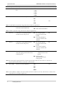
7
RPF
Enables the Remote Power Failure
notification (ASM-10/8/R only)
ON – RPF notification enabled
ON
OFF – RPF notification disabled
Note: Set RPF to OFF when using ASM-10/8 in multipoint applications.
8
PIN 18
Controls the local analog loopback
activation via the DTE pin 18
EN – The analog loopback
activation from the DTE
enabled
EN
DIS – The analog loopback
activation from the DTE
disabled
9
PIN 21
Controls the remote digital loopback
activation via the DTE pin 21
EN – The remote loopback
activation from the DTE
enabled
EN
DIS – The remote loopback
activation from the DTE
disabled
10
CHAS GND
CONN
Controls the connection between the CONN – Signal ground is
connected to the frame
ASM-10/8 signal ground and the frame
ground
(chassis) ground
DIS – Signal ground is
disconnected from the
frame ground
Note: Disconnecting the signal ground from the frame ground may render the unit unsafe for connection to
unprotected telecommunication networks in some locations.
11
RCV IMPD
Selects receive line impedance
150
150
300
600
HIGH
Note: Set RCV IMPD to 150Ω for the master modem and the last modem in the line, and all others to HIGH, when
using ASM-10/8 in multipoint applications.
2
Installing ASM-10/8
ASM-10/8 Installation and Operation Manual
Quick Start Guide
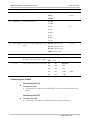
Item Jumper
Description
Values
12
Selects delay between RTS and CTS
0 msec
CTS-DLY
Default Setting
8 msec
8 msec
64 msec
13
Data Rate
Selects the data rate
0 – 19.2
1 – 14.4
2 – 9.6
9.6
3 – 7.2
4 – 4.8
5 – 3.6
6 – 2.4
7 – 1.2
14
XMT TIMING Selects the transmit timing signal clock INT CK – Internal clock
source
EXT CK – External clock
INT CK
RCV CK – Receive clock
ASYNC – Async mode
15
DIP Switch
The DIP switch consists of four sections. The S1 section is reserved for future use.
S2
Selects the amount of stop bit
shortening to be used in async mode.
S3, S4
ON – 25%
OFF
OFF – 12.5%
Selects character length in async mode S3
S4
No of bits
OFF
OFF
8 BIT
OFF
ON
9 BIT
ON
OFF
10 BIT
ON
ON
11 BIT
10 BIT
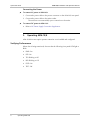
Connecting the Cables
Connecting the Line
To connect the line:
•
Connect the line cable to the terminal block connector on the ASM-10/8 rear
panel.
Connecting the DTE
To connect the DTE:
•
Connect the DTE cable to the DB-25 female rear panel connector.
Installing ASM-10/8
3
ASM-10/8 Installation and Operation Manual
Quick Start Guide
Connecting the Power
To connect AC power to ASM-10/8:
1. Connect the power cable to the power connector on the ASM-10/8 rear panel.
2. Connect the power cable to the mains outlet.
The unit turns on automatically upon connection to the mains.
To connect DC power to ASM-10/8:
•
2.
Refer to DC Power Supply Connection Supplement.
Operating ASM-10/8
ASM-10/8 does not require operator attention once installed and configured.
Verifying Performance
When data is being transferred, observe that the following front panel LEDs light or
blink:
4
•
PWR: On
•
RTS: On
•
TD: Blinking or Off
•
RD: Blinking or Off
•
DCD: On
•
TEST: Off.
Operating ASM-10/8
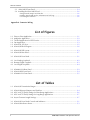
Contents
Chapter 1. Introduction
1.1 Overview..................................................................................................................... 1-1
Versions................................................................................................................................ 1-1
Applications.......................................................................................................................... 1-1
Features................................................................................................................................ 1-3
1.2 Physical Description..................................................................................................... 1-5
1.3 Functional Description................................................................................................. 1-6
Encoder................................................................................................................................ 1-6
Modulation Timing ............................................................................................................... 1-7
Async to Sync Converter ....................................................................................................... 1-7
XMT Level and XMT Filter (Optional) .................................................................................... 1-7
Receiver ............................................................................................................................... 1-7
Remote Power Failure (RPF) Indication ................................................................................. 1-8
V.54 Diagnostics ................................................................................................................... 1-8
1.4 Technical Specifications............................................................................................... 1-9
Chapter 2. Installation and Setup
2.1 Site Requirements and Prerequisites ............................................................................ 2-1
2.2 Package Contents ........................................................................................................ 2-1
2.3 Installation and Setup .................................................................................................. 2-2
Setting the Internal Jumpers .................................................................................................. 2-2
Configuration Considerations ................................................................................................ 2-6
Connecting the Interfaces ..................................................................................................... 2-7
Connecting the Power .......................................................................................................... 2-8
Chapter 3. Operation
3.1 Front Panel Controls and Indicators ............................................................................. 3-1
3.2 Operating ASM-10/8 ................................................................................................... 3-2
Turning On ASM-10/8 ..........................................................................................................3-2
Normal Indications ............................................................................................................... 3-3
Turning Off ASM-10/8 ..........................................................................................................3-3
Chapter 4. Diagnostics
4.1 V.54 Loopback Tests.................................................................................................... 4-1
Local Analog Loopback (LLB) ................................................................................................ 4-2
Remote Digital Loopback (RLB)............................................................................................. 4-3
Local Digital Loopback (DIG) ................................................................................................ 4-4
Chapter 5. ASM-10/8/R Card Version
5.1 ASM-MN-214 Card Cage............................................................................................. 5-1
Line Connector..................................................................................................................... 5-1
DB-25 DTE Connector.......................................................................................................... 5-1
5.2 Power Supply .............................................................................................................. 5-3
AC Supply ............................................................................................................................ 5-3
DC Supply............................................................................................................................ 5-3
Power Supply with Redundancy............................................................................................ 5-3
ASM-10/8 Installation and Operation Manual
i
Table of Contents
5.3 ASM-10/8/R Front Panel .............................................................................................. 5-4
5.4 Installing the ASM-10/8/R Card .................................................................................... 5-6
Setting Internal Jumpers and Switches ................................................................................... 5-6
Installing ASM-10/8/R into the ASM-MN-214 Card Cage ....................................................... 5-6
Connecting the Interfaces ..................................................................................................... 5-6
Appendix A. Connector Wiring
List of Figures
1-1.
1-2.
1-3.
1-4.
1-5.
1-6.
Point-to-Point Application ..................................................................................................... 1-1
Multipoint Application........................................................................................................... 1-2
Tail-End Application for DDS Service..................................................................................... 1-2
Star Application ..................................................................................................................... 1-3
ASM-10/8, 3D View .............................................................................................................. 1-5
ASM-10/8 Block Diagram ...................................................................................................... 1-6
2-1. ASM-10/8 PCB Layout........................................................................................................... 2-3
2-2. ASM-10/8 Rear Panel ............................................................................................................ 2-7
3-1. ASM-10/8 Front Panel ........................................................................................................... 3-1
4-1. Local Analog Loopback ......................................................................................................... 4-2
4-2. Remote Digital Loopback ...................................................................................................... 4-3
4-3. Local Digital Loopback .......................................................................................................... 4-4
5-1. ASM-MN-214 Rear Panel ...................................................................................................... 5-2
5-2. ASM-10/8/R Front Panel ........................................................................................................ 5-4
5-3. ASM-MN-214 Front Panel ..................................................................................................... 5-5
List of Tables
1-1. ASM-10/8 Transmission Ranges ............................................................................................. 1-4
2-1.
2-2.
2-3.
2-4.
ASM-10/8 Internal Jumpers and Switches .............................................................................. 2-4
AGC and CTS Delay Settings for Short-Range Applications .................................................... 2-6
AGC and CTS Delay Settings for Long-Range Applications ..................................................... 2-7
Async Character Length Settings ............................................................................................ 2-7
3-1. ASM-10/8 Front Panel Controls and Indicators ...................................................................... 3-1
3-2. ASM-10/8 Indicator Status ..................................................................................................... 3-3
ii
ASM-10/8 Installation and Operation Manual
Chapter 1
Introduction
1.1 Overview
ASM-10/8 is a short-range modem, which operates over unconditioned lines. It
can function in full or half-duplex mode with synchronous or asynchronous
transmission format. ASM-10/8 has an extended range of up to 28 km (17.4 miles)
on 24 AWG wire, and more depending on wire gauge and data rate
(see Table 1-1). It operates at eight selectable rates ranging from 1.2 kbps to
19.2 kbps.
Versions
The following versions of the modem available:
•
ASM-10/8 standalone unit
•
ASM-10/8/R, a plug-in card for installation in the ASM-MN-214 19-inch
modem rack, holding up to 14 cards.
Power Supply
•
AC – 115 VAC or 230 VAC
•
DC – 18 to 60 VDC.
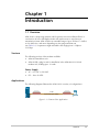
Applications
The following diagrams illustrate the ASM-10/8 in a variety of configurations:
4-wire
ASM-10/8
Up to 55 km (34.1 miles)
ASM-10/8
Figure 1-1. Point-to-Point Application
Overview
1-1
ASM-10/8 Installation and Operation Manual
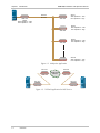
Chapter 1 Introduction
XMT Pair
RCV Pair
ASM-10/8
ASM-10/8
Slave 1
XMT Impedance – 150Ω
RCV Impedance – High
Master
XMT Impedance – LOW
RCV Impedance – 150Ω
ASM-10/8
Slave 2
XMT Impedance – 150Ω
RCV Impedance – High
ASM-10/8
Slave 3
XMT Impedance – 150Ω
RCV Impedance – High
ASM-10/8
Slave N
XMT Impedance – 150Ω
RCV Impedance – High
Figure 1-2. Multipoint Application
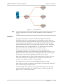
EXT CLK
ASM-10/8
EXT CLK
Digital Service
Network
ASM-10/8
RCV CLK
RCV CLK
ASM-10/8
ASM-10/8
Figure 1-3. Tail-End Application for DDS Service
1-2
Overview
ASM-10/8 Installation and Operation Manual
Chapter 1 Introduction
ASM-10/8
Slave
ASM-10/8
Master
ASM-10/8
Slave
ASM-10/8
Slave
Figure 1-4. Star Application
Note
In the star application, set the XMT and RCV impedance of all the modems to
150Ω.
Features
The ASM-10/8 modem uses conditioned differential diphase modulation
(EUROCOM Std. D1) to provide protection from background noise, eliminate
normal line distortion and permit efficient transmission and reception of serial data
over twisted pair cable. ASM-10/8 is connected to the telephone line through
isolation transformers which, in conjunction with electronic circuitry, protect the
device against AC or DC voltage fluctuations. The protection circuitry permits
operation of ASM-10/8 even when DC is connected to the line.
The modem's transmit level and transmit and receive impedances are
independently selectable. The transmit timing is either provided internally, or it is
derived externally from the data terminal or regenerated from the receive signal.
The modem's receive timing is regenerated from the receive signal.
ASM-10/8 communicates over lines in synchronous mode only. When set to the
asynchronous mode, ASM-10/8 performs an asynchronous to synchronous
conversion in compliance with ITU V.14 bis standard.
The unit has line protection circuits against lightning and power surges.
ASM-10/8 also operates in conjunction with the MCS-10 dual modem card of the
MCS-12 Monitoring and Control System.
The ASM-10/8/R card is capable of sensing and indicating power failure on the
remote ASM-10/8 standalone unit. When this feature is enabled, the RPF LED
lights in case of a remote power failure.
Overview
1-3
ASM-10/8 Installation and Operation Manual
Chapter 1 Introduction
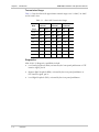
Transmission Range
Table 1-1 lists the ASM-10/8 approximate transmit ranges over 19 AWG, 24 AWG
and 26 AWG wires.
Table 1-1. ASM-10/8 Transmission Ranges
Data
Rate
19 AWG
(0.9 mm)
24 AWG
(0.5 mm)
26 AWG
(0.4 mm)
[kbps]
km
miles
km
miles
km
miles
19.2
22.5
14.0
10.0
6.2
7.5
4.7
14.4
24.5
15.3
11.0
6.9
8.2
5.1
9.6
29.0
18.1
13.0
8.1
9.5
5.9
7.2
33.0
20.5
15.0
9.4
11.0
6.9
4.8
36.0
22.5
16.0
10.0
12.0
7.5
3.6
40.0
25.0
18.0
11.2
13.5
8.4
2.4
47.0
29.3
21.0
13.1
15.7
9.8
1.2
55.0
34.3
28.0
17.5
21.0
13.1
Diagnostics
ASM-10/8 V.54 diagnostic capabilities include:
1-4
•
Local analog loopback (ANA), activated by the front-panel pushbutton or DTE
interface signal, pin 18
•
Remote digital loopback (REM), activated by the front-panel pushbutton or
DTE interface signal, pin 21
•
Local digital loopback (DIG), activated by the front-panel pushbutton.
Overview
ASM-10/8 Installation and Operation Manual
Chapter 1 Introduction
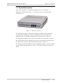
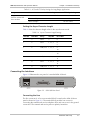
1.2 Physical Description
ASM-10/8 is available as a standalone desktop unit or as a card for the
ASM-MN-214 modem rack. Figure 1-5 shows the 3D view of the ASM-10/8
standalone unit.
Figure 1-5. ASM-10/8, 3D View
The front panel includes six LEDs, which display the status of power, data flow,
control signals and diagnostics. Three front-panel switches control the three
loopback modes. For detailed description of the front panel, see Chapter 3.
The back panel includes an AC cord connector with fuse, an interface connector,
and a terminal block with a ground connection for connecting the telephone lines.
The ASM-10/8 rear panel is described in greater detail, in Chapter 2.
The internal switches and jumpers can be configured to support a variety of modes
for operating the modem. Refer to Chapter 2 for details on jumper location and
setting.
Physical Description
1-5
ASM-10/8 Installation and Operation Manual
Chapter 1 Introduction
1.3 Functional Description
This section contains functional descriptions of the circuit blocks of ASM-10/8,
primarily those circuits which are required for setting the desired modem
configuration (see Figure 1-6).
RTS
CTS
ENCODER
CONTROL
TXC
EXT.
CLK
MODULATOR
TIMING
POWER
SUPPLY
RV CLK
REM
LOOP 2
RLB
COMMAND
GENERATOR
RPF
GENERATOR
(ASM-10-SA
ONLY)
SELECTABLE
XMT AMPLIFIER
SYNC
TXD
ENCODER
MODULATOR
ASYNC TO
SYNC CONV
LOOP 3
ASYNC
XMT
DIG LPBK
ANA LOOP
ANALPBK
RCV RLB
RLB
COMMAND
DECODER
2W
104 (BB) RXD
DECODER
AUTOMATIC
EQUALIZER
RCV
FILTER
4W
RCV
115 (BB) RXC
TIMING
RECOVERY
109 (CF) DCD
CARRIER
DETECT
AGC
DATA RATE
RPF LED
PIN 22
RPF
DECODER
(ASM-10-R
ONLY)
RPF RESET
PIN 11
Figure 1-6. ASM-10/8 Block Diagram
Encoder
The encoder modulates the input data from the DTE using the conditional diphase
modulation technique.
The encoder can be configured to operate in one of the following different modes:
1-6
•
4-wire full duplex
•
4-wire half duplex
•
2-wire half duplex
•
4-wire multipoint
•
2-wire multipoint.
Functional Description
ASM-10/8 Installation and Operation Manual
Chapter 1 Introduction
Modulation Timing
This circuit supplies the transmit clock signal to the encoder.
The following clock sources are available:
•
INT.CK (internal clock) – from the modem's internal crystal oscillator)
•
EXT.CK (external clock) – from DTE, pin 24
•
RCV.CK (receive clock) – recovered from the received signal
•
ASYNC – asynchronous timing for working with the async to sync converter in
asynchronous applications.
Timing options are selected using the XMT TIMING jumpers.
Async to Sync Converter
ASM-10/8 has an internal asynchronous to synchronous converter (used for
asynchronous data).
Asynchronous transmission is provided by internal conversion from asynchronous
to synchronous mode in compliance with ITU V.22 bis. In this standard, the
modem compensates for frequency deviation between the modem and the DTE
by adjusting the length of the stop bit of the async character. If the modem's
frequency is higher than the DTE, the local converter extends the stop bit. If the
modem's frequency is lower than the DTE, the local converter deletes one stop bit
in every four (25%) or eight (12.5%) characters. The remote converter will add a
shorter stop bit (shorter by 12.5% or 25%) before sending the data to the remote
DTE.
Shortening the stop bits by 12.5% is suitable for frequency deviations up to 1.1%
and shortening the stop bits by 25% is suitable for frequency deviations up to
2.3%.
XMT Level and XMT Filter (Optional)
Four options are available for the XMT level (signal level): 0, -3, -6, -9 dBm.
An optional output filter for the line is available. This filter complies with
Bell 43401 standard and meets British Telecom requirements.
Receiver
The receiver comprises several circuits, as shown in the block diagram (see
Figure 1-6).
•
The receive filter removes all the out-of-band frequencies.
•
The automatic equalizer comprises several equalizers which are activated
according to baud rate.
•
The digital AGC automatically compensates for the attenuation of the line.
Functional Description
1-7
Chapter 1 Introduction
ASM-10/8 Installation and Operation Manual
Remote Power Failure (RPF) Indication
The Remote Power Failure feature notifies the user at a central location of a power
failure in a remote modem.
The remote power failure feature can be configured only when the ASM-10/8
standalone unit (remote) operates in conjunction with the rack-mounted card
ASM-10/8/R (central). When a power failure occurs, ASM-10/8 standalone unit
transmits a special tone, which is detected by ASM-10/8/R and causes the RPF LED
to turn on. A special pushbutton – RPF – located on the front panel of ASM-10/8/R,
allows the user to reset the RPF LED. The RPF jumper in the standalone unit enables
or disables the feature. RPF should be disabled for multipoint applications.
V.54 Diagnostics
ASM-10/8 features V.54 diagnostic capabilities for performing local analog
loopback and local and remote digital loopback. When the modem is set to the
digital loopback mode, the operator at either end of the line can test both
modems and the line. The loopback is controlled either with front-panel
pushbuttons or via pin 18 and pin 21 of the V.24/RS-232 interface.
1-8
Functional Description
ASM-10/8 Installation and Operation Manual
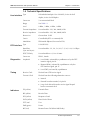
Chapter 1 Introduction
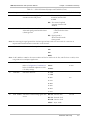
1.4 Technical Specifications
Line Interface Type
Connector
5-screw terminal block
Range
See Table 1-1
Level
0 dBm, -3 dBm, -6 dBm, -9 dBm
Transmit Impedance
User-selectable: 150, 300, 600Ω, LOW
Receive Impedance
User-selectable: 150, 300, 600Ω, HIGH
Return Loss
Greater than 15 dB
Carrier
Controlled by RTS or constantly ON
Modulation
Differential diphase (Eurocom Std. D1)
DTE Interface Type
Diagnostics
Unloaded twisted pair 19 to 26 AWG; 2-wire for half
duplex, 4-wire for full duplex
V.24 (RS-232)
Baud Rate
(Sync and Async)
User-selectable: 1.2, 2.4, 3.6, 4.8, 7.2, 9.6, 14.4, 19.2 kbps
RTS/CTS Delay
User-selectable to: 0, 8 or 64 msec
Connector
DB-25, female
Loopbacks
• Local (ANA), activated by a pushbutton or by the DTE
interface signal, pin 18.
• Remote (REM), activated by a pushbutton or by the
DTE interface signal, pin 21
• Local (DIG), activated by a pushbutton
Timing
Receive Clock
Derived from CDP receive signal
Transmit Clock
Derived from the following alternative sources:
• Internal
• External from the terminal, via pin 24
• Loop clock derived from the receive signal looped
back as a transmit clock
Indicators
TD (yellow)
Transmit Data
RD (yellow)
Receive Data
RTS (yellow)
Request to Send
DCD (yellow)
Data Carrier Detect
TEST (red)
Test
PWR (green)
Power
RPF (red)
Remote Power Fail (ASM-10/8/R only)
Technical Specifications
1-9
ASM-10/8 Installation and Operation Manual
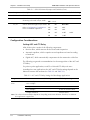
Chapter 1 Introduction
Physical
Power
ASM-10/8
Height
43 mm / 1.7 in
Width
215 mm / 8.5 in
Depth
243 mm / 9.5 in
Weight
956g
ASM-10/8/R
Fits one slot of the ASM-MN-214 modem rack
AC
115 or 230 VAC (±10%), 47 to 63 Hz
DC
18 to 60 VDC
Power Consumption
3W
Fuses
0.25A/250V (115 VAC)
/ 2.1 lb
0.125A/250V (230 VAC)
Protection
Environment Temperature
Humidity
1-10
Technical Specifications
AC/DC overvoltage protection circuits are connected via
transformers to transmit and receive lines
0–50°C / 32–122°F
0 to 90%, non-condensing
Chapter 2
Installation and Setup
This chapter describes installation and setup procedures for the standalone
ASM-10/8 modem.
ASM-10/8 is delivered completely assembled. It is designed for tabletop or 19-inch
rack installation. For instructions on installation of a single unit or two units in a
19-inch rack, refer to the Rack Mounting Kit for 19-inch Racks guide that comes
with the RM kit.
After installing the unit, refer to Chapter 3 to assure normal operation.
In case a problem encountered, refer to Chapter 4 for test and diagnostic
instructions.
Internal settings, adjustment, maintenance, and repairs may be performed
only by a skilled technician who is aware of the hazards involved.
Always observe standard safety precautions during installation, operation, and
Warning maintenance of this product.
2.1 Site Requirements and Prerequisites
An AC-powered ASM-10/8 should be installed within 1.5m (5 ft) of an easily
accessible grounded AC outlet. The outlet should furnish 115 VAC or 230 VAC
(depending on rated voltage of unit).
A DC-powered ASM-10/8 unit requires DC power supply capable of furnishing
18–60 VDC. In order to prevent a fire hazard, a suitable fuse should be installed in
the DC line.
Allow at least 90 cm (36 in) of frontal clearance for operating and maintenance
accessibility. Allow at least 10 cm (4 in) clearance at the rear of the unit for signal
lines and interface cables.
The ambient operating temperature of ASM-10/8 is 0 to 50°C (32 to 122°F) at
relative humidity of 90%, non-condensing.
2.2 Package Contents
The ASM-10/8 package includes the following items:
• One ASM-10/8 unit
•
Last Mile Access and Intelligent Modems CD
•
AC power cord or DC power supply connector kit
•
RM-17 rack mount kit (if ordered).
Package Contents
2-1
Chapter 2 Installation and Setup
ASM-10/8 Installation and Operation Manual
2.3 Installation and Setup
ASM-10/8 is a standalone device intended for tabletop or bench installation. It is
delivered completely assembled. No provisions are made for bolting the ASM-10/8
to the tabletop.
To install ASM-10/8:
1. Determine the required configuration of the modem according to your
application, and set the internal jumpers and switches accordingly
(see Figure 2-1 and Table 2-1).
2. Connect the line (see Connecting the Line below).
3. Connect the DTE interface (see Connecting the DTE below).
4. Connect power to the unit (see Connecting the Power below).
Setting the Internal Jumpers
This section provides information on the functions of the internal jumpers and
switches, to help you in the selection of the correct settings for particular
application, and gives you step-by-step instructions for performing the internal
settings. The default settings are also listed.
To set the ASM-10/8 internal jumpers:
1. Open the ASM-10/8 case.
2. Set the ASM-10/8 internal jumpers and switches, referring to Table 2-1.
3. Reinstall the ASM-10/8 cover.
Access to the inside of the equipment is permitted only to the authorized and
qualified personnel.
To avoid accidental electric shock, always disconnect the interface cables and
Warning the power cord before removing the unit from its casing.
Line voltages are present inside ASM-10/8 when it is connected to power
and/or the lines. Moreover, under certain fault conditions, dangerous voltages
may appear on the lines connected to the unit.
Any adjustment, maintenance and repair of the opened instrument under
voltage must be avoided as much as possible and, when inevitable, should be
carried out only by a skilled technician who is aware of the hazard involved.
Capacitors inside the unit may still be charged even after the unit has been
disconnected from its source of power.
Caution ASM-10/8 contains components sensitive to electrostatic discharge (ESD). To
prevent ESD damage, avoid touching the internal components, and before moving
jumpers, touch the ASM-10/8 frame.
2-2
Installation and Setup
ASM-10/8 Installation and Operation Manual
Chapter 2 Installation and Setup
Opening the ASM-10/8 Case
To reach the internal jumpers and switches of ASM-10/8, it is necessary to open its
case.
To open the ASM-10/8 case:
1. Disconnect all the cables connected to ASM-10/8.
2. Turn the unit over (bottom facing up).
3. Unscrew the four cover screws.
4. Turn the unit over (bottom facing down).
5. After the four screws released, remove the ASM-10/8 top cover by pulling it
straight up.
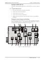
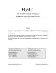
Setting the Internal Jumpers and Switches
The internal jumpers and switches located on the ASM-10/8 printed circuit board
(PCB) are identified in Figure 2-1. Their numbers under heading "Item" in Table 2-1
correspond to the identification numbers shown in Figure 2-1.
LEN
OFF
ON
OFF
ON
8 BIT ON=25%
9 BIT
10 BIT
11 BIT OFF=12.5%
11
S2(%)
70 1
6
2
54 3
CTS-DLY
RCV IMPD
150
300
600
HIGH
S4
OFF
OFF
ON
ON
12
0 ms
8 ms
64 ms
S3
13
10
CHAS GND
CONN
14
DIS
15
GND
RCV
XMT
S1
S2
S3
S4
XMT IMPD
0 dbm
-3 dbm
-6 dbm
-9 dbm
INT
EX
RCV
ASY
PIN 18
600
300
150
LOW
XMT LEVEL
XMT TIMING
EN DIS
DTE
PIN 21
SWITCH
2W/4W
CARRIER
EN DIS
2W 4W
CTRL ON
EN DIS
RPF
ON OFF
GND
AGC
Fuse
CTRL ON
1
2
3
4
5
6
7
8
9
Figure 2-1. ASM-10/8 PCB Layout
Installation and Setup
2-3
ASM-10/8 Installation and Operation Manual
Chapter 2 Installation and Setup
Table 2-1. ASM-10/8 Internal Jumpers and Switches
Item Jumper
Description
Values
1
Enables activation of DIG, ANA and
REM loopbacks via the front-panel
pushbuttons
EN
EN – The loopbacks can be
activated via the front panel
Selects 4-wire or 2-wire operation
4W – 4-wire operation
SWITCH
2
2W/4W
Default Setting
DIS – The loopbacks cannot be
activated via the front
panel
4W
2W – 2-wire operation
Note: When using 2-wire operation, connect both wires to the XMT screws of the terminal.
3
AGC
Controls the AGC operation
ON – AGC is always active
Refer to Configuration Considerations
below for detailed explanation of the
AGC settings.
CTRL – ACG is active only when
DCD turns on
ON
Note: When set to CTRL, ACG remains at its last level of amplification if DCD goes off.
4
CARRIER
Selects the transmit carrier mode.
ON – Transmit carrier is
constantly On
ON
CTRL – Transmit carrier is On
only if RTS is high
Note: Set CARRIER to CTRL when using ASM-10/8 in multipoint applications.
5
XMT LEVEL
Selects the transmit output level to the 0 dbm
line
-3 dbm
0 dbm
-6 dbm
-9 dbm
6
XMT IMPD
Selects transmit line impedance
600
300
150
150
LOW
Note: Set XMT IMPD to LOW when using ASM-10/8 in multipoint applications.
7
RPF
Enables the Remote Power Failure
notification (ASM-10/8/R only)
ON – RPF notification enabled
ON
OFF – RPF notification disabled
Note: Set RPF to OFF when using ASM-10/8 in multipoint applications.
8
PIN 18
Controls the local analog loopback
activation via the DTE pin 18
EN – The analog loopback
activation from the DTE
enabled
DIS – The analog loopback
activation from the DTE
disabled
2-4
Installation and Setup
EN
ASM-10/8 Installation and Operation Manual
Chapter 2 Installation and Setup
Table 2-1. ASM-10/8 Internal Jumpers and Switches (Cont.)
Item Jumper
Description
Values
Default Setting
9
Controls the remote digital loopback
activation via the DTE pin 21
EN – The remote loopback
activation from the DTE
enabled
EN
PIN 21
DIS – The remote loopback
activation from the DTE
disabled
10
CHAS GND
CONN
Controls the connection between the CONN – Signal ground is
connected to the frame
ASM-10/8 signal ground and the frame
ground
(chassis) ground
DIS – Signal ground is
disconnected from the
frame ground
Note: Disconnecting the signal ground from the frame ground may render the unit unsafe for connection to
unprotected telecommunication networks in some locations.
11
RCV IMPD
Selects receive line impedance
150
150
300
600
HIGH
Note: Set RCV IMPD to 150Ω for the master modem and the last modem in the line, and all others to HIGH, when
using ASM-10/8 in multipoint applications.
12
13
CTS-DLY
Data Rate
Selects delay between RTS and CTS
0 msec
Refer to Configuration Considerations
below for detailed explanation of the
CTS delay settings.
8 msec
Selects the data rate
0 – 19.2
8 msec
64 msec
1 – 14.4
2 – 9.6
9.6
3 – 7.2
4 – 4.8
5 – 3.6
6 – 2.4
7 – 1.2
14
XMT TIMING Selects the transmit timing signal clock INT CK – Internal clock
source
EXT CK – External clock
INT CK
RCV CK – Receive clock
ASYNC – Async mode
Installation and Setup
2-5
ASM-10/8 Installation and Operation Manual
Chapter 2 Installation and Setup
Table 2-1. ASM-10/8 Internal Jumpers and Switches (Cont.)
Item Jumper
Description
15
DIP Switch
The DIP switch consists of four sections. The S1 section is reserved for future use.
S2
Selects the amount of stop bit
shortening to be used in async mode.
S3, S4
Values
Default Setting
ON – 25%
OFF
OFF – 12.5%
Selects character length in async mode S3
S4
No of bits
Refer to Configuration Considerations
below for detailed explanation.
OFF
OFF
8 BIT
OFF
ON
9 BIT
ON
OFF
10 BIT
ON
ON
11 BIT
10 BIT
Configuration Considerations
Setting AGC and CTS Delay
ASM-10/8 receiver consists of the following components:
•
Receiver filter, which removes all the out-of-band frequencies.
•
Automatic equalizer, which comprises several equalizers activated according
to baud rate.
•
Digital AGC, which automatically compensates for the attenuation of the line.
The following are general recommendations for the setup position of the AGC and
CTS delay:
For point-to-point applications, set AGC to ON and CTS delay to 8 msec.
In multipoint or star applications, the AGC and CTS delay settings depend on the
distances between the modems (see Table 2-2 and Table 2-3).
Table 2-2. AGC and CTS Delay Settings for Short-Range Applications
Range
Rate
AGC Setting
CTS Delay Setting
Less than 4.5 km
6 km
9.6 to 19.2 kbps
3.6 to 7.2 kbps
CTRL (master and slave)
0 msec (master)
4.8 kbps
8 msec (slave)
2.4 to 4.8 kbps
8 msec or 64 msec (slave)
2.4 kbps and below
64 msec (slave)
Note: The selection between delays depends on the polling environment behavior. Therefore, it is different
from application to application
2-6
Installation and Setup
ASM-10/8 Installation and Operation Manual
Chapter 2 Installation and Setup
Table 2-3. AGC and CTS Delay Settings for Long-Range Applications
Range
Rate
Long or uneven distances
between master and
slave modems
AGC Setting
CTS Delay Setting
ON (master and slave)
0 msec (master)
Above 9.6 kbps
8 msec (slave)
Below 9.6 kbps
64 msec (slave)
Setting the Async Character Length
Table 2-4 lists the character length values in the asynchronous mode.
Table 2-4. Async Character Length Settings
Start Bit
Data Bits
Parity
Stop Bit
No of Bits
1
5
None
2
8
1
6
None
1, 1.5, 2
8
9
1
6
Odd, Even
1, 1.5, 2
9
10
1
7
None
1, 1.5, 2
9
10
1
7
Odd, Even
1, 1.5, 2
10
11
1
8
None
1, 1.5, 2
10
11
1
8
Odd, Even
1, 1.5, 2
11
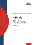
Connecting the Interfaces
Figure 2-2 illustrates the rear panel of a standard ASM-10/8 unit.
DTE
XMT RCV GND
Figure 2-2. ASM-10/8 Rear Panel
Connecting the Line
The line connector is a five-screw terminal block, located on the ASM-10/8 rear
panel as shown in Figure 2-2. The terminal block provides four screws for
connecting the transmit and receive telephone lines and one screw for the ground
connection. The transmit and receive pairs are polarity-insensitive.
Installation and Setup
2-7
Chapter 2 Installation and Setup
ASM-10/8 Installation and Operation Manual
To connect the line:
1. Connect the ground wire to the terminal designated GND (optional).
2. Connect the transmit pair to the terminals marked XMT.
3. Connect the receive pair to the terminals marked RCV.
Note
Use only XMT pair for 2-wire operation.
Connecting the DTE
The rear-panel DTE connector provides interface for data input/output, clock
reference and control signal exchange between ASM-10/8 and the DTE. The DTE
connector is V.24/RS-232, D-type 25-pin female connector. Connector pin
allocations appear in Appendix A.
Connecting the Power
The power is supplied to the ASM-10/8 unit through the 1.5m (5 ft) standard
power cable terminated in a standard 3-prong plug. The cable is provided with the
unit. DC power connection is described in the DC Power Supply Supplement at
the end of the manual.
The integral fuse holder, located above the AC socket, contains two fuses
(0.125A/250V or 0.25A/250V, slow-blow). The upper fuse is spare and can be
used for blown fuse replacement.
The unit has no power switch. Operation starts when the power is applied to
the rear-panel POWER connector.
Before switching on this instrument, the protective earth terminals of this
Warning instrument must be connected to the protective ground conductor of the
power cord. The power plug shall only be inserted in a power outlet provided
with a protective earth contact. The protective action must not be negated by
use of an extension cord (power cable) without a protective conductor
(grounding).
Make sure that only fuses with the required rated current, as marked on the
ASM-10/8 rear panel, are used for replacement. The use of repaired fuses and
the short-circuiting of the fuse holders is forbidden.
Whenever it is likely that the protection offered by fuses has been impaired,
the instrument must be made inoperative and be secured against any
unintended operation.
To connect power to ASM-10/8:
1. Connect the power cable to the connector on the ASM-10/8 rear panel.
2. Connect the power cable to the mains outlet.
The unit turns on automatically upon connection to the mains.
2-8
Installation and Setup
Chapter 3
Operation
This chapter provides the following information for the ASM-10/8 standalone
modem:
•
ASM-10/8 front-panel indicators and controls
•
Operating procedures (turn-on, front-panel indications, performance
monitoring and turn-off).
Installation procedures given in Chapter 2 must be completed and checked before
attempting to operate ASM-10/8.
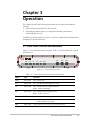
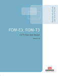
3.1 Front Panel Controls and Indicators
Figure 3-1 shows the ASM-10/8 front panel. Table 3-1 lists the ASM-10/8 controls
and indicators.
DIG
PWR
RTS
TD
RD
DCD
ANA
REM
TEST
Figure 3-1. ASM-10/8 Front Panel
Table 3-1. ASM-10/8 Front Panel Controls and Indicators
Name
Type
Function
PWR
Green LED
ON – Power is on.
RTS
Yellow LED
ON – The DTE activates Request To Send.
TD
Yellow LED
ON – Steady SPACE is being transmitted.
Blinks – Data is transmitted.
RD
Yellow LED
ON – Steady SPACE is being received.
Blinks – Data is received.
DCD
Yellow LED
ON – A valid receive signal is present.
TEST
Yellow LED
ON – ASM-10/8 is in any of the three loopback modes, or the
PATT pushbutton is pressed.
ERR
Yellow LED
ON or blinks if errors are present in the test pattern.
Front Panel Controls and Indicators
3-1
ASM-10/8 Installation and Operation Manual
Chapter 3 Operation
Table 3-1. ASM-10/8 Front Panel Controls and Indicators (Cont.)
Name
Type
Function
DIG
Pushbutton
The digital loopback pushbutton causes the local ASM-10/8 to
loop received data to its transmitter (see Figure 4-3).
ANA
Pushbutton
The local loopback (V.54 loop 3) pushbutton causes the local
ASM-10/8 to loop its transmitter output back to its receiver
(see Figure 4-1). This loopback may also be activated from the DTE
when the PIN 18 jumper is set to EN.
REM
Pushbutton
The remote digital loopback (V.54 Loop 2) pushbutton causes the
remote ASM-10/8 to loop received data to its transmitter
(see Figure 4-2). This loopback may be also activated from the
terminal when the PIN 21 jumper is set to EN.
Note
The PIN 18 and PIN 21 jumpers control the LLB and RLB activation only from the
DTE interface. The jumper settings do not affect the ANA and REM pushbutton
operation.
3.2 Operating ASM-10/8
Turning On ASM-10/8
ASM-10/8 is turned on as soon as power is connected. When power is connected,
the PWR indicator lights up and remains lit as long as ASM-10/8 receives power.
ASM-10/8 requires no operator attention once installed, with the exception of
occasional monitoring of front panel indicators. Intervention is only required when
the modem must be configured to new operational requirements, or the diagnostic
tests must be performed.
3-2
Operating ASM-10/8
ASM-10/8 Installation and Operation Manual
Chapter 3 Operation
Normal Indications
Table 3-2 shows the correct status of the ASM-10/8 indicators after the local and
remote modem are synchronized and data is being transferred.
Table 3-2. ASM-10/8 Indicator Status
Indicator
Status
PWR
ON
RTS
ON
TD
Blinking or OFF
RD
Blinking or OFF
DCD
ON
ERR
OFF
TEST
OFF
If the LEDs do not reflect the above status, ensure that:
•
One modem is set to internal or external clock, and the other to receive clock.
•
The four front-panel pushbuttons are in the OFF position.
Turning Off ASM-10/8
To turn off the modem, remove the power cord from the power source.
Operating ASM-10/8
3-3
Chapter 3 Operation
3-4
Operating ASM-10/8
ASM-10/8 Installation and Operation Manual
Chapter 4
Diagnostics
This chapter contains procedures for performing system diagnostic tests for
ASM-10/8. Use the test procedures provided in this chapter to:
•
Verify normal system operation
•
Isolate faulty equipment
•
Identify other sources of system malfunction.
The tests are activated by control pushbuttons on the ASM-10/8 front panel and
monitored via LED indicators. For description of ASM-10/8 controls and indicators
and their functionality, see Chapter 3.
4.1 V.54 Loopback Tests
ASM-10/8 supports several types of loopback tests for evaluating the operation of
the data system equipment and its line circuits. Using these loopbacks, you can
test communication between the attached equipment, internal circuitry of the
local and remote modems.
Loopback test are best performed in the following order:
1. Local analog loopback
2. Remote digital loopback
3. Local digital loopback.
Before testing the operation of the data system equipment and line circuits, ensure
that all the units are powered up and configured properly.
Note
If you want to run the LLB and RLB tests via the DTE interface pins, ensure that the
PIN 18 and PIN 21 jumpers are set to EN (see Table 2-1 and Figure 2-1).
V.54 Loopback Tests
4-1
ASM-10/8 Installation and Operation Manual
Chapter 4 Diagnostics
Local Analog Loopback (LLB)
The local analog loopback (LLB) test checks the performance of the local
ASM-10/8 modem, the local DTE, and the connections between them (see
Figure 4-1). The test is performed separately at the local and the remote site.
ANA
Depressed
Data
Clock
Transmit
Line
Interface
DTE
Clock
Data
Receive
ASM-10/8
Figure 4-1. Local Analog Loopback
To perform the local analog loopback test:
1. Press the ANA pushbutton.
The TEST LED on the ASM-10/8 front panel lights up. The modem's
transmit output is now connected to its own receiver.
2. Execute the local analog loopback with one of the following methods:
Using the DTE configured to the half duplex operation and checking the
echoed data stream.
Using an external BER tester.
If the BER test indicates an error-free data stream, but the DTE test indicates
a fault, verify that the cable between the DTE and ASM-10/8 is properly
connected. If the problem persists, follow the DTE manufacturer's test
procedures.
3. To isolate a communication line problem, perform the LLB loopback at the
opposite end. If both LLB tests are error-free, the fault is probably in the
communication line or in the line interfaces.
4. After completing the test or correcting the fault, press ANA pushbutton again
to restore it to the Off position.
4-2
V.54 Loopback Tests
ASM-10/8 Installation and Operation Manual
Chapter 4 Diagnostics
Remote Digital Loopback (RLB)
The remote digital loopback (RLB) test checks the performance of the local and the
remote ASM-10/8 units and their connecting lines. The remote digital loopback
sets a loop at the remote ASM-10/8 unit from the DTE coupled to the local unit
(see Figure 4-2).
REM
Pressed
Data
Clock
Transmit
Receive
Link
Interface
Local
DTE
Clock
Data
Link
Interface
Receive
Remote
DTE
Transmit
Local ASM-10/8
Remote ASM-10/8
Figure 4-2. Remote Digital Loopback
To activate the remote digital loopback:
1. Press the REM pushbutton on the local ASM-10/8 front panel.
The TEST LED on each ASM-10/8 front panel lights up. The receive output
of the remote modem is looped back to the receiver.
2. Perform the BERT test as explained above for the local analog loopback test.
If an error occurs, while the local analog loopback test described above, was
successful for both the local and remote modems, the line or the line circuits
of the local or the remote unit are not operating properly.
3. After completing the test or correcting the fault, press REM pushbutton again
to restore it to the Off position.
V.54 Loopback Tests
4-3
ASM-10/8 Installation and Operation Manual
Chapter 4 Diagnostics
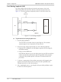
Local Digital Loopback (DIG)
The local digital loopback (DIG) test allows the operator at the remote end to
check the performance of the local and remote ASM-10/8 units, and their
connecting lines. The DIG test loops the received data back to the remote
ASM-10/8 (see Figure 4-3). The local digital loopback test is equivalent to activating
the remote loopback from the remote ASM-10/8.
DIG
Pressed
Data
Transmit
Receive
Link
Interface
Local
DTE
Clock
Link
Interface
Remote
DTE
Data
Receive
Transmit
Local ASM-10/8
Clock
Remote ASM-10/8
Figure 4-3. Local Digital Loopback
To activate the local digital loopback:
•
Press the DIG pushbutton on the local ASM-10/8 front panel.
The TEST LED lights up.
4-4
V.54 Loopback Tests
Chapter 5
ASM-10/8/R Card Version
This chapter describes the ASM-10/8/R card, designed for installation in the
ASM-MN-214 card cage. The chapter contains the following sections:
•
The ASM-MN-214 card cage
•
ASM-MN-214 power supply
•
The ASM-10/8/R front panel
•
Installing the ASM-10/8/R card.
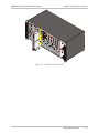
5.1 ASM-MN-214 Card Cage
The ASM-MN-214 card cage contains one or two power supplies and up to
14 plug-in cards. The card types can be ASM-10/8/R or other RAD rack version
modems/converters – any combination of up to 14 plug-in cards.
For each of the 14 cards, the rear panel (see Figure 5-1) contains a male connector
for the terminal block and a DB-25 connector. A protection cover protects the
terminal block connectors.
Line Connector
The terminal block (see Figure 5-1) is to be attached to the rear panel terminal
block connectors. It contains screws for connecting the transmit and receive pairs
and ground, if present.
The ASM-MN-214 card cage is also available with BNC coaxial unbalanced line
connectors.
DB-25 DTE Connector
The 25-pin D-type female interface connector provides all interface signals for the
digital interfaces.
ASM-MN-214 Card Cage
5-1
Chapter 5 ASM-10/8/R Card Version
ASM-10/8 Installation and Operation Manual
Terminal
Block
Figure 5-1. ASM-MN-214 Rear Panel
5-2
ASM-MN-214 Card Cage
ASM-10/8 Installation and Operation Manual
Chapter 5 ASM-10/8/R Card Version
5.2 Power Supply
Power is supplied to the ASM-10/8/R card from the ASM-MN-214 power supply
via the chassis. Each ASM-10/8/R card has two fuses, which protect the entire
system against power failure resulting from a short circuit in one card.
The ASM-MN-214 card cage can accept both AC or DC power supplies. LED
indicators located on the ASM-MN-214 front panel (see Figure 5-3) show activity
when the power supply is connected to the mains plug. The power supply
supports the full card cage with any combination of cards.
AC Supply
The AC power supply of the ASM-MN-214 is 100, 115, or 230 VAC, ±10%,
47 to 63 Hz.
DC Supply
The DC power supply is -48 VDC (-36 to -72 VDC) or 24 VDC (18 to 32 VDC). It
uses a DC/DC converter module to provide the power required for the cards.
Power Supply with Redundancy
This special ordering option is equipped with two separate power supplies,
operating together and sharing the load of the whole card cage. If either of the
power supplies fails, the other one will continue to supply power to the full card
cage.
Two LED indicators show activity of each power supply. They should both light
when mains power is provided.
Note
It is possible to combine AC and DC power supplies in the same cage.
Power Supply
5-3
ASM-10/8 Installation and Operation Manual
Chapter 5 ASM-10/8/R Card Version
5.3 ASM-10/8/R Front Panel
Figure 5-2 shows the ASM-10/8/R card front panel. The LEDs and pushbuttons of
the card version are identical in their functionality to those of the standalone
device. For this information, refer to Chapter 3.
The ASM-10/8/R front panel features one additional LED indicator (RPF) and one
additional pushbutton (RPF). The RPF (Remote Power Failure) LED turns on when
a power failure occurs in the remote standalone ASM-10/8 unit. The RPF
pushbutton resets the RPF LED after the power failure.
PWR
RTS
TD
RD
DCD
TEST
RPF
DIG
ANA
REM
ASM-10
Figure 5-2. ASM-10/8/R Front Panel
5-4
ASM-10/8/R Front Panel
ASM-10/8 Installation and Operation Manual
Chapter 5 ASM-10/8/R Card Version
Figure 5-3. ASM-MN-214 Front Panel
ASM-10/8/R Front Panel
5-5
Chapter 5 ASM-10/8/R Card Version
ASM-10/8 Installation and Operation Manual
5.4 Installing the ASM-10/8/R Card
Setting Internal Jumpers and Switches
The ASM-10/8/R internal jumpers and switches are similar in their functionality to
those of the standalone unit. For the details on the internal settings, refer to
Figure 2-1 and Table 2-1.
Installing ASM-10/8/R into the ASM-MN-214 Card Cage
To install the ASM-10/8/R card in the ASM-MN-214 card cage:
1. Install the ASM-MN-214 card cage in the 19-inch rack.
2. Insert the ASM-10/8/R card into one of the ASM-MN-214 slots.
3. Push the card into the cage until it is fully inserted into the edge connector
inside the rack.
4. Tighten the screws on front panel of the modem card.
Connecting the Interfaces
ASM-10/8/R uses the ASM-MN-214 rear panel terminal block ports for the line
connections. The 25-pin D-type female connector serves as a DTE port.
1. Remove the protection cover from the terminal block connectors.
2. Connect the terminal block to the ASM-MN-214 terminal block connector.
3. Connect the line to the terminal block as follows: connect transmit pair to the
terminals marked XMT, the receive pair to the terminals marked RCV, and the
fifth screw to ground (optional).
4. Connect the DTE cable to the DB-25 connector.
5. Connect power to the ASM-MN-214 card cage:
To connect AC power, connect the power cable to the mains supply.
To connect DC power, refer to DC Power Supply Connection Supplement
of the ASM-MN-214 Installation and Operation manual.
Warning
5-6
The ASM-MN-214 card cage has no power switch. Operation starts when the
power is applied to the rear panel POWER connector. When applying power,
first connect the plug of the power cord to the ASM-MN-214 POWER
connector and then to the mains power source (outlet).
Installing the ASM-10/8/R Card
Appendix A
Connector Wiring
A.1 DTE Interface Pin Assignment
The V.24/RS-232 DTE interface of ASM-10/8 terminates in DB-25 female
connector, wired in accordance with Table A-1.
Table A-1. V.24/RS-232 Connector Pinout
V.24
RS-232
DTE
Pin
Signal Identity
Description
101
AA
1
Protective
Ground
Chassis ground. May be isolated from Signal Ground (refer to
the CHAS GND jumper description in Table 2-1).
102
AB
7
Signal Ground
Common signal and DC power supply ground.
N/A
N/A
9
10
+8 volts
–8 volts
Output +8 VDC
Output –8 VDC
103
BA
2
Transmitted Data
Serial digital data from a terminal or other source. If
accompanied by an external data rate clock data, transitions
must occur on positive-going transitions of the external
transmit output clock.
104
BB
3
Received Data
Serial digital data at the output of the modem receiver. The
data transitions occur at the rising edge of the clock.
105
CA
4
Request to Send
A positive level to ASM-10/8 when data transmission is desired.
106
CB
5
Clear to Send
A positive level from ASM-10/8 with selectable delay, after
receipt of Request to Send and when ASM-10/8 is ready to
transmit.
A positive level from ASM-10/8, power is on and ASM-10/8 is
not in the Local Digital Loopback mode or has not received a
Remote Digital Loopback signal from the remote unit.
107
CC
6
Data Set Ready
109
CF
8
Receive Line
Signal Detector
(Carrier Detect)
A positive level from ASM-10/8, except when a loss of the
received input is detected or when Data Set Ready is negative.
113
DA
24
External Trans.
Serial Clock
A serial data rate clock input from the data source. Positive
clock transitions correspond to data transitions.
114
DB
15
Transmitter
Signal
Element Timing
A transmit data rate clock for use by external data source.
Positive clock transitions correspond to data transitions.
DTE Interface Pin Assignment
A-1
ASM-10/8 Installation and Operation Manual
Appendix A Connector Wiring
Table A-1. V.24/RS-232 Connector Pinout (Cont.)
V.24
RS-232
DTE
Pin
Signal Identity
Description
115
DD
17
Receiver Signal
A receive data rate clock output for use by external data sink.
Positive clock transitions correspond to data transitions.
142
25
Test Indicator
A positive control signal output from ASM-10/8 during any test
mode.
141
18
Loop 3
Test Command
A control signal input; when on, commands ASM-10/8 into
Local Analog Loopback (V.54 Loop 3).
140
21
Loop 2
Test Command
A control signal input; when on, commands ASM-10/8 to send
a Remote Digital Loopback command (V.54 Loop 2) to the
remote ASM-10/8.
11
RPF LED Reset
A positive level to the ASM-10/8/R (from management system)
resets the RPF LED in ASM-10/8/R.
22
Remote Power
Failure
A positive level from ASM-10/8/R when remote power failure
occurs.
A-2
DTE Interface Pin Assignment
DC Power Supply Connection – Terminal Block Connector
Note: Ignore this supplement if the unit is AC-powered.
Certain DC-powered units are equipped with a plastic 3-pin VDC-IN power input connector, located on the unit
rear panel. Supplied with such a unit, is a mating Terminal Block (TB) type connector plug for attaching to your
power supply cable.
Connect the wires of your power supply cable to the TB plug, according to the voltage polarity and assembly
instructions provided below.
Caution: Prepare all connections to the TB plug
before inserting it into the unit’s VDC-IN connector.
DC Power Input
Connector
20 mm
(on unit panel)
Wire stripping
dimensions
5 mm
Preparing and Connecting the TB Plug
Refer to Figure 1 for assistance.
Terminal screws
1. Strip the insulation of your power supply
wires according to the dimensions shown.
2. Place each wire lead into the appropriate TB
plug terminal according to the voltage
polarity mapping shown in Figure 2. (If a
terminal is not already open, loosen its
screw). Afterwards, tighten close the three
terminal screws.
Nylon cable tie
See Figure 2
for mapping
3. Pull a nylon cable tie (supplied) around the
power supply cable to secure it firmly to the
TB plug grip (pass the tie through the holes
on the grip).
Mating
TB Connector
Plug
DC power
cable
TB plug grip
Figure 1
4. Isolate the exposed terminal screws/wire leads using a plastic
sleeve or insulating tape, to prevent the possibility of short-circuit.
TB Connector
Plug
5. Connect the assembled power supply cable to the unit by
inserting the TB plug into the unit’s VDC-IN connector until it
snaps into place.
0
DC Power Supply Wire Voltage Polarity
Refer to Figure 2 for proper mapping of the power supply wire leads
to the TB plug’s three terminals.
Chassis (frame)
Ground
+
Positive pole
Warning:
• Reversing the wire voltage polarity can cause damage to the unit!
• Always connect a ground (earth) wire to the TB plug’s Chassis
(frame) Ground terminal. Connecting the unit without a protective
ground, or interruption of the grounding (for example, by using an
extension power cord without a grounding conductor) can cause
harm to the unit or to the equipment connected to it!
-48
or
(-24
)
24/48VDC Negative pole
Figure 2
SUP-220-01/02
24 Raoul Wallenberg St., Tel Aviv 69719, Israel
Tel: +972-3-6458181, Fax: +972-3-6483331, +972-3-6498250
E-mail: [email protected] , Web site: http://www.rad.com
Customer Response Form
RAD Data Communications would like your help in improving its product documentation.
Please complete and return this form by mail or by fax or send us an e-mail with your
comments.
Thank you for your assistance!
ASM-10/8
Manual Name: ______________________________________________________________
600-200-08/02
Publication Number: __________________________________________________________
Please grade the manual according to the following factors:
Installation instructions
Operating instructions
Manual organization
Illustrations
The manual as a whole
Excellent
Good
Fair
Poor
Very Poor
❒
❒
❒
❒
❒
❒
❒
❒
❒
❒
❒
❒
❒
❒
❒
❒
❒
❒
❒
❒
❒
❒
❒
❒
❒
What did you like about the manual?
___________________________________________________________________________
___________________________________________________________________________
___________________________________________________________________________
___________________________________________________________________________
___________________________________________________________________________
Error Report
Type of Error(s)
❒
Incompatibility with product
or Problem(s):
❒
Difficulty in understanding text
❒
Regulatory information (Safety, Compliance, Warnings, etc.)
❒
Difficulty in finding needed information
❒
Missing information
❒
Illogical flow of information
❒
Style (spelling, grammar, references, etc.)
❒
Appearance
❒
Other _________
Please list the exact page numbers with the error(s), detail the errors you found (information missing,
unclear or inadequately explained, etc.) and attach the page to your fax, if necessary.
_________________________________________________________________________________________
_________________________________________________________________________________________
_________________________________________________________________________________________
_________________________________________________________________________________________
Please add any comments or suggestions you may have.
_________________________________________________________________________________________
_________________________________________________________________________________________
_________________________________________________________________________________________
You are:
❒
Distributor
❒
End user
❒
VAR
❒
Other ________________________
Who is your distributor?
_______________________________
Your name and company: ___________________________________________________________
Job title: __________________________________________________________________________
Address: __________________________________________________________________________
Direct telephone number and extension: _______________________________________________
Fax number: ______________________________________________________________________
E-mail: _____________________________________________________________________
www.rad.com
INTERNATIONAL HEADQUARTERS:
24 Raoul Wallenberg Street, Tel Aviv 69719, Israel, Tel: 972-3-6458181
Fax: 972-3-6498250, 972-3-6474436, Email: [email protected]
U.S. HEADQUARTERS:
900 Corporate Drive, Mahwah, N.J. 07430, Tel: (201) 529-1100
Toll Free: 1-800-444-7234, Fax: (201) 529-5777, Email: [email protected]
Publication No. 600-200-08/02