1
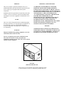
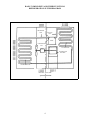
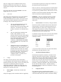
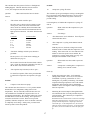
SERVICE MANUAL
FOR
6700, 7000, 8000 & 9000 SERIES
AIR CONDITIONERS
(MECHANICAL CONTROLS ONLY)
FOR WALL MOUNT THERMOSTATS AND LOW VOLTAGE CONTROL
CIRCUITS, REFER TO THEIR APPROPRIATE MANUALS
FOR ELECTRICAL CHECKOUTS ON DELTA T AND DELTA TX
AIR CONDITIONERS, REFER TO MANUAL R-332 (2-86)
PREFACE
!WARNING - SHOCK HAZARD!
This service manual is primarily intended for the use of
qualified individuals specially trained and experienced in the
service of this type of equipment and related system
components.
TO PREVENT THE POSSIBILITY OF SEVERE
PERSONAL INJURY, DEATH OR EQUIPMENT
DAMAGE DUE TO ELECTRICAL SHOCK, ALWAYS
BE SURE THE POWER SUPPLY TO THE APPLIANCE
IS DISCONNECTED BEFORE DOING ANY WORK ON
THE APPLIANCE. THIS CAN NORMALLY BE
ACCOMPLISHED BY SWITCHING THE BREAKER
FOR THE AIR CONDITIONER TO OFF,
DISCONNECTING ALL EXTERNAL ELECTRICAL
CONNECTIONS AND CORDS, SWITCHING ON
BOARD ELECTRICAL GENERATORS AND
INVERTORS TO OFF, AND REMOVING THE CABLE
FROM EACH POSITIVE TERMINAL ON ALL
STORAGE AND STARTING BATTERIES.
Installation and service personnel are required by some states,
counties or cities to be licensed. Persons not qualified shall
not attempt to service this equipment or interpret this service
manual.
SCOPE
This is not a basic refrigeration and air conditioning manual
and does not therefore, cover the principles of refrigeration or
air conditioning. The user of this manual should have
already accomplished a thorough study of refrigeration and
air conditioning.
WARNING
Improper installation may damage equipment, can create
a hazard and will void the warranty.
DANGER
SOME DIAGNOSTIC TESTING MAY BE DONE ON
ENERGIZED CIRCUITS. ELECTRICAL SHOCK CAN
OCCUR IF NOT TESTED PROPERLY. TESTING TO
BE DONE BY QUALIFIED TECHNICIANS ONLY.
The use of components not tested in combination with
these units will void the warranty, may make the
equipment in violation of state codes, may create a hazard
and may ruin the equipment.
6757-7201
SERVICE TEST DEVICE
This test device is an invaluable aid in quickly diagnosing repairs
to all RV Products roof top air conditioners produced after 1979.
TABLE OF CONTENTS
Basic Components and Their Functions
Refrigeration System Diagram
I.
Refrigeration Circuit . . . . . . . . . . . . . . . . . . . . . . . . . . . . . . . . . . . . . . . . . .
5
II.
Air Handling Circuits . . . . . . . . . . . . . . . . . . . . . . . . . . . . . . . . . . . . . . . . .
6
III.
Electric Power Circuits . . . . . . . . . . . . . . . . . . . . . . . . . . . . . . . . . . . . . . . .
6
IV.
Tools And Equipment . . . . . . . . . . . . . . . . . . . . . . . . . . . . . . . . . . . . . . . . .
10
V.
Service Problems And Their Solutions . . . . . . . . . . . . . . . . . . . . . . . . . . . .
13
VI.
Typical Wiring Diagrams . . . . . . . . . . . . . . . . . . . . . . . . . . . . . . . . . . . . . .
20
QUICK DIAGNOSIS CHART
Note: This charge represents problems with units having mechanical controls - if the air conditioner
is equipped with a wall thermostat, please refer to the appropriate manual.
Possible Causes
Ref. Page Number
Fan And Compressor Will Not Run
No Power 115V
Selector Switch
14
14
Fan Will Not Run
Selector Switch
Fan Run Capacitor
Motor
Wiring (Mis-wired)
17
17
17
20-21
Compressor Will Not Run
Selector Switch
Thermostat
Low Voltage
Overload
Compressor
Wiring (Mis-wired)
PTCR or Potential Relay
Start Capacitor
Run Capacitor
15
15
15
15
15
20-21
16-17
20-21
Problem
Cooling Performance
19
BASIC COMPONENTS AND THEIR FUNCTIONS
REFRIGERATION SYSTEM DIAGRAM
DISCHARGE
LINE
SUCTION
LINE
COMP.
CONDENSER
FAN
EVAPORATOR
FAN
MOTOR
EVAPORATOR
BLOWER
CONDENSER COIL
HIGH SIDE
LOW SIDE
4
systems exists from the discharge port of the compressor to
the cap tube. The low side is from the cap tube to the
compressor cylinders. The dividing points then are the cap
tube and compressor cylinders.
The purpose of this part of the Service Manual is to acquaint
the Service Technician with the system components so that
when he has a problem, he can intelligently analyze and
isolate the problem and efficiently correct it.
1.
BASIC COMPONENTS AND
THEIR FUNCTIONS
The high side pressure is also referred to as head pressure or
condensing pressure, and the low side pressure is also
referred to as suction pressure or evaporator pressure.
I. REFRIGERANT CIRCUIT
It is impossible to state the exact pressures that will exist in
the high side or low side because those pressures will both
vary with different temperature and humidity conditions both
inside and outside the recreational vehicle.
Refrigerant Charge
The systems covered by this service manual all use a
refrigerant called monochlorodifluoromethane (better known
as R-22).
3.
The refrigerant enters the cap tube from the condenser as a
warm high pressure liquid. As the refrigerant flows through
the small diameter cap tube, the pressure drops rather rapidly.
As the pressure drops, a tiny amount of the liquid refrigerant
will vaporize. This vaporization requires heat which must
come from the liquid refrigerant itself - thus the liquid
temperature is constantly lowered as it passes through the cap
tube. As the refrigerant leaves the cap tube, it is still mostly
liquid; however, a small portion has changed to a vapor
called flash gas. When the liquid refrigerant passes from the
cap tube to the evaporator, it is at low side pressure and will
therefore, vaporize at low temperature as it picks up heat
from the air being conditioned.
We know that R-22 is not a deadly gas because many of us
have breathed it many times and we are still living. But, no
one has said that R-22 is completely safe to breathe; so, a
wise service technician will always keep a work space well
ventilated if R-22 can escape into the air. IF R-22 COMES
IN CONTACT WITH ANY OPEN FLAME, PHOSGENE
GAS IS CREATED AND ONE SHOULD AVOID
BREATHING THE FUMES.
The temperature at which R-22 changes to toxic gases and
acids varies with the amount or concentration of water
present i.e. the greater the concentration of water, the lower
the temperature and vice versa. High temperatures normally
exist inside a refrigeration circuit, so we must keep the circuit
as absolutely dry as possible to prevent the formation of
destructive acids.
4.
Evaporator Coil
The purpose of the finned evaporator coil is to transfer the
heat from the warm and moist indoor air to the cold low
pressure refrigerant.
Liquid R-22 in the atmosphere will always be at about -41°.
Therefore, always wear safety glasses when working with
R-22.
As the heat leaves the air, the air temperature drops and some
of the moisture in the air condenses from a vapor to a liquid.
The liquid water (condensate) is drained onto the roof of the
recreational vehicle. As the heat enters the refrigerant in the
evaporator, it causes the refrigerant to evaporate (change
from a liquid to a vapor). Thus the name – evaporator.
Again unburned R-22 is not a deadly gas, so by using
reasonable safety precautions, the service technician will not
be hurt by it.
In addition to being almost non-toxic, R-22 is nonflammable, non-explosive, non-corrosive and miscible
(mixable) with oil. It also has a rather high latent heat value.
This means that is must absorb a large amount of heat per lb.
to vaporize or change from a liquid to a vapor; and it must
give up a large amount of heat per lb. to condense or change
from a vapor to a liquid.
2.
Capillary Tube (Cap Tube)
The refrigerant remains at nearly constant temperature
(called evaporator temperature or low side saturation
temperature) in the evaporator as long as there are both liquid
and vapor together. However, near the outlet of the
evaporator coil, all of the liquid has boiled (evaporated) away
and from there on the temperature of the vapor rises (the
vapor becomes superheated). It is necessary that the vapor
become superheated because it passes through the suction
line to the compressor and the compressor can only pump
superheated vapor – any vapor (which might be present if the
vapor were not superheated) could cause serious mechanical
damage to the compressor.
High and Low Sides
It is customary for air conditioning technicians to use the
terms high side and low side. In doing so, we refer to the
parts of the refrigeration circuit which, when the system is
running, contain high pressure refrigerant (high side) and
low pressure refrigerant (low side). The high side of these
5
5.
saturation temperature, we call its condition sub-cooled
liquid.
Suction Line
The suction line is the tube which carries the superheated
vapor refrigerant from the evaporator to the compressor.
6.
During all of the three processes in the condenser (desuperheating, condensing, sub-cooling), the refrigerant gives
up heat; but most of the heat is given up during the
condensing process.
Compressor
The compressor is called a hermetic compressor which means
that it is completely sealed (welded together). It is, therefore,
not internally field serviceable. Inside the compressor
housing are basically:
a)
an electric motor which drives the compressor,
b)
a pump which is designed to pump superheated
vapor only,
c)
a supply of special refrigeration oil. A small portion
of the oil will circulate out through the system with
the refrigerant, but will constantly return to the
compressor with the refrigerant, so the compressor
will not run out of oil.
7.
II. AIR HANDLING CIRCUITS
1.
One motor turns both the condenser fan blade and evaporator
air blower. The condenser (outdoor) fan is an axial flow
(propeller) type and the evaporator (indoor) fan or blower is a
centrifugal (squirrel cage) type.
2.
Filters
The filters should always be in place when the system is
running. More important than their purpose of cleaning the
air in the living space is the protection the filters give the
evaporator coil. Without filters, a wet evaporator coil will
quickly stop up so that adequate air cannot pass through it.
Filters must be installed to completely fill the filter rack so
that no air can flow around them or by-pass them and carry
dust, lint, etc. to the evaporator. To clean an evaporator that
has not been properly protected by its filter, the entire unit
must be removed from the recreational vehicle and the coil
cleaned with special detergent and water.
Discharge Line
The discharge line carries the refrigerant out of the
compressor and to the condenser coil. Remember that as the
refrigerant entered the compressor, it was superheated vapor.
The refrigerant enters the compressor, where more heat is
added and is compressed into a smaller space. The
refrigerant, therefore, leaves the compressor highly
superheated – so if the discharge line is hot to the touch
(burns), don’t be surprised – it should be.
8.
Motors and Fans
III. ELECTRIC POWER CIRCUITS
1.
Condenser Coil
Safety
Voltage (electrical pressure), whether high or low, will not
hurt you. It is the current through vital parts of your body
that does the damage, and under the right conditions, 115
volts (domestic USA) is plenty to drive a deadly dose of
current (amperes) through your body.
The purpose of the finned condenser coil is to transfer heat
from the high pressure refrigerant to the warm outdoor air.
As the outdoor air passes over the coil, the heat transfer will
cause the air temperature to rise. Thus the condenser
discharge air will be several degrees warmer than the
condenser entering air.
Another imminent danger from electric shocks in addition to
electrocution is reaction. An electrical shock causes
uncontrollable muscular contractions which can cause further
injuries.
As the refrigerant passes through the first few tubes of the
condenser, its temperature will be lowered or it will be desuperheated. After the refrigerant is de-superheated, it will
begin to condense or change from a vapor to a liquid and will
remain at a nearly constant temperature throughout almost all
of the remainder of the coil. This temperature is called the
condensing temperature or high side saturation temperature
and will always be higher than the condenser entering air
temperature.
Remember that electricity can be very dangerous, but you can
safely work with it. In order to be safe, you must know what
you are doing. You must work deliberately and carefully.
You must think safety before each move.
THINK SAFETY
Near the bottom of the condenser, the refrigerant will all be
condensed to a liquid and from there on its temperature will
drop to more nearly the temperature of the outdoor air. After
the temperature of the refrigerant drops below condensing or
6
2.
Power Supply - from Commercial Utility
1)
Wire Size
The power supply to the air conditioner must be wired
through a circuit breaker or time delay fuse. The power
supply must be 20 amperes and 12 AWG wire minimum.
Any size
an on-board motor generator, its wiring may be identical to
the commercial power described above.
There are, however, some motor generators on which both the
current carrying leads are insulated from the ground. That is
to say; there is no grounded neutral, so there will be 115 volts
larger at any time may be used and should be used if the
length of the wire is over 32 feet.
2)
(domestic USA) between the black and white leads, but there
will be 0 volts between either lead and ground.
Color Code
The electric power from the electric service panel should be
delivered through a 3 conductor cable and the Service
Technician should check to be sure the color code is correct.
The electrician probably installed the cable with the colors
according to code, but don’t bet your life on it.
WARNING: The service technician must keep in mind
when checking to make sure that the power is turned off.
Check only between the hot (black) lead and the neutral
(white) lead.
4.
a)
b)
c)
3)
The wire with black insulation is the hot
wire and there should be 115 volts
(domestic USA) between it and either of the
other wires. All switches, fuses, circuit
breakers, disconnects, etc. should be in this
line.
The selector switch is mounted on the left side of the interior
ceiling assembly. The selector switch allows the unit to be
operated on high to low blower only, or high to low blower
with compressor operation for cooling. On heating and
cooling models, the selector switch can also switch in the
electric heater at low blower operation only.
The wire with the white insulation is the
neutral. There should be 115 volts
(domestic USA) between the neutral and the
hot (black) wire, but there should be 0 volts
between the neutral and the ground (the
green wire or the frame of the air
conditioner). There must be no switches,
fuses, disconnects, etc. of any kind in the
neutral wire.
To check the selector switch, remove wires from the terminals
and rotate the switch to the proper position and read
continuity as follows:
The third wire may be covered with green
insulation or it may be a bare metal wire. It
is the ground wire. There must be 115 volts
(domestic USA) between this wire and the
hot (black) wire and 0 volts between it and
the neutral (white) wire. The ground wire
must be securely fastened to the air
conditioner cabinet. A ground screw is
provided for this purpose.
Terminals
Switch Position
L-1-3
L-1
L-2
L-1-4
L-2-4
Lo Heat
Lo Fan
Hi Fan
Lo Cool
Hi Cool
* If you do not wish to remove the wires from each terminal,
disconnect the 9 pin plug from the a/c unit.
5.
Thermostat (Mechanical Rotary)
The thermostat (temperature controller) is mounted on the
right side of the interior ceiling assembly. The thermostat
controls the on-off cycle of the compressor when the selector
switch is in the cooling position and on heating and cooling
models, the on-off cycle of the electric heater when the
selector switch is in the heating position. The thermostat is
actuated by sensing the temperature of the return air through
the vent where the bulb is located. Terminal continuity
should make and break if ambient air temperature is between
65 and 90 degrees F.
Voltage
The voltage (electrical pressure) at the unit should be
115 volts (domestic USA) and all electrical components will
perform best at the correct voltage. However, the voltage will
vary and the air conditioning system will perform
satisfactorily within plus or minus 10% of the rated (115)
voltage (domestic USA). Therefore, the voltage has to be
between 103.5 volts and 126.5 volts.
6.
3.
Selector Switch - Free Delivery Ceiling Assemblies
Power Supply - Generated by on-board motor
generator
Compressor Motor
The compressor motor is located inside the hermetic
compressor housing and therefore not accessible for service or
visual observation in the field. However, the motor winding
If the power supply for the recreational vehicle is supplied by
7
condition can be analyzed by using an ohm meter. Be sure to
remove all the leads from the compressor terminals before
making this check.
through the condenser coil.
1)
If the resistance between any two terminals is 0
ohms, the motor windings are shorted.
An important step in installing a replacement fan motor is to
check the direction of rotation before it is installed. On all
models, the condenser fan pulls the air through the coil.
2)
If the resistance between any terminal and the
compressor housing is anything but infinity, the
winding is grounded.
If the resistance between any two terminals is
infinity, the winding is open.
3)
* Some models use a squirrel cage on both ends of the motor.
Fan Motor Check Procedure
If a fan motor refuses to perform properly, it can be checked
in the following manner:
On a good compressor, the highest resistance will be between
the R (run) and S (start) terminals. The lowest resistance will
be between the C (common) and R (run) terminals. The
intermediate resistance will be between the C (common) and
S (start) terminals. Notice that compressors have the
identification of the terminals marked on either the terminal
cover or on the compressor housing.
7.
9.
Overload Switch
Be sure the motor leads are connected to the proper
points –
a)
The black wire from the motor connects to a
black wire inside a wire nut then the black
wire connects through the disconnect plug
to the selector switch. The red wire from
the motor connects to a red wire in a wire
nut then the red wire connects through the
disconnect plug to the selector switch.
Mounted on the outside of the compressor housing is a two
terminal overload switch. Note: We have a few models with
internal overloads that are non-serviceable. The switch is
connected in series with the common terminal, so if the
switch opens, it will cut the power to the compressor motor.
The switch will open as the result of either or both of two
conditions that could be harmful to the compressor.
1)
High Amperes (Current)
The switch contains a heater which increases in temperature
as the current increases. The higher temperature warps the
switch and will cause it to open before the windings reach a
dangerous temperature.
2)
The white wire from the motor connects to
the fan capacitor or a white wire in a wire
nut then the white wire connects through
the disconnect plug to the thermostat.
c)
The brown wires from the motor connect to
the fan capacitor.
High Temperature (Thermal)
The switch is clamped tightly against the compressor housing
and located close to the windings. Therefore, as the windings
reach a higher temperature, it takes less current to cause the
switch to open.
2.
As can be seen, the switch is always affected by a
combination of current to the compressor and winding
temperature.
8.
b)
To check the motor winding resistance carefully,
check the resistance between each of the wires and
ground (preferably a copper refrigerant tube for a
good connection). These readings must be infinity.
Any continuity means the windings are grounded.
If there is a reading of 0 between any two leads, the
motor is shorted and is no good. If there is a reading
of infinity (no meter reading at all) between any two
leads, the winding is open and the motor is no good.
Fan Motor
The air conditioning unit has one double end shaft fan motor.
On one shaft end is mounted a centrifugal or squirrel cage
blower which draws air (return air) out of the recreational
vehicle and blows the conditioned air down into the
recreational vehicle. On the other end is mounted an axial
flow or propellor type fan which circulates outdoor air
Note:
8
A motor with 2 brown leads will have an
O reading between 1 brown wire and either
the black or white wire.
9.
Good Capacitor
Run Capacitors
If the capacitor is good, the indicator will move from infinity
(the left side), towards zero ohms and slowly return back to
infinity. Reverse the leads and test again. The result should
be the same.
The purpose of the run capacitors is to give the motors
starting torque and to maintain high power factor during
running. The run capacitors are always connected between
the start and run or main terminals of the motor.
On some older models, one of the terminals of the run
capacitors will have a red dot (the identified terminal). The
identified terminal should always be connected to the run or
main terminal of the motor and to the neutral line.
CAPACITOR
OHM METER
CAPACITORS
Capacitor Check
There are several capacitor test devices available. The ohm
meter is one of them. The ohm meter cannot verify a
capacitors MFD (microfarrad) value. However, the following
procedures will show you how to use an ohm meter to
determine if the capacitor is good, open, shorted or grounded.
HIGH
LOW
OK
Indicator sweeps back and forth
as shown above. Capacitor is good.
Before testing any capacitor, always perform the following
procedure:
*
This test must be done with a analog type meter.
Open Capacitor
a)
Disconnect all electrical power to the air conditioner.
b)
Discharge the capacitor with a 20,000 ohm (approx.
3 watt) resistor or larger.
If the capacitor is open, the indicator will show no deflection
or movement. Reverse the leads and test again. If there is no
indicator movement on the second test, the capacitor is open.
Open capacitors are defective and must be replaced.
c)
You may discharge capacitors with a standard volt
meter if you use a scale over 500 volts and touch the
leads (one lead to each side of the capacitor). The
volt meter will discharge the capacitor.
d)
Identify and disconnect the wiring from the
capacitor.
e)
Set and zero the ohm meter on the “highest” scale.
OPEN
HIGH
LOW
Indicator shows no movement.
Needle stays to the left side. If needle
shows no movement after reversing the
leads, the capacitor is open.
When testing for a good, open or shorted capacitor,
perform the following checks: Place the ohm meter
leads across the capacitor terminals (one lead on
each terminal) and perform a continuity test. Then
observe the action of the meter needle or indicator.
Reverse the leads and test again. The result should
be the same. Note: If the capacitor had not been
properly discharged, a false reading could be
indicated on the first test. Always test several times
(reversing the leads with each test). This will verify
the capacitors condition.
Shorted Capacitor
If the capacitor is shorted, the indicator will move towards and sometimes hit zero
ohms, and will stay there. This indicates a completed circuit through the inside of
the capacitor (shorted). Shorted capacitors are defective and must be replaced.
HIGH
SHORT
Indicator moves to the right side
of the scale and stays there
(indicating a completed circuit).
The capacitor is shorted.
9
LOW
connected in series with the start winding and it gets
the generated voltage of the start winding portion of
the compressor motor. This generated voltage is
much higher than line voltage and varies with the
speed of the motor. Therefore, since the relay is
designed to open the contacts at 75% of normal
running voltage (measured between terminals #5 and
#2), the contacts will open (thus disconnect the start
capacitor) at approximately 75% of normal running
speed.
Grounded Capacitor
When testing for a grounded capacitor, perform a continuity
check between each terminal on the capacitor and the bare
metal of the capacitor case. Any indication of a circuit
(constant resistance) from either terminal to case, indicates a
grounded capacitor. Grounded capacitors are defective and
must be replaced.
CAPACITOR
11.
OHM METER
LOW
12.
13.
The limit switch is a safety switch and is mounted in the
heating element frame. It will open and break the circuit on
temperature rise in case the air flow through the heater
becomes low enough to cause the heater to overheat.
(A)
IV. TOOLS AND EQUIPMENT
In order to service the equipment covered by this Service
Manual, a technician will need all the common mechanics
tools such as wrenches, screwdrivers, hammers, etc.
Start (Potential) Relay
The start relay consists of –
1)
2)
Limit Switch
Start Capacitor
Most models use a start capacitor and a start relay to give the
compressor high starting torque. The compressor will,
therefore, start against normal pressure difference (head
pressure minus suction pressure) even when shut down for a
short period of time. The start relay will disconnect the start
capacitor when the motor reaches approximately 75%
running speed.
11.
Heating Element
The heating element is a resistance heater of 1600 watts (5600
BTUH) capacity and is connected across the line when the
selector is set for heating and the thermostat is calling for heat.
The current draw of the heater (element only) will be 13.3
amperes at 120 volts (domestic USA models).
Indicator moves to the right side of
the scale and stays there
(indicating a completed circuit).
The capacitor is grounded.
10.
Positive Temperature Coefficient Resistor
(Commonly Known As PTCR Start
Device)
The resistor acts like a potential relay in that it takes the start
capacitor out of the start circuit, but uses resistance of
electrical flow (back EMF from compressor) instead of
opening a set of contacts. The service person should be careful
handling the resistors. They will be hot during operation (up
to 160 degrees F). The air conditioner needs to be off for 3-5
minutes during cycle time and when servicing to let the
resistor cool down.
GROUNDED
HIGH
(B)
In addition to the common mechanics tools, in order to do
refrigeration and electrical work, he will need special tools and
equipment such as:
Normally closed contacts internally between
terminals #1 and #2 which switch in the start
capacitor in parallel to the run capacitor during shut
down and then switch out the start capacitor when
the motor reaches approximately 75% normal
running speed.
1.
2.
3.
4.
5.
6.
7.
8.
9.
10.
A high voltage coil internally between terminals #5
and #2 to actuate the contacts. The coil is too weak
on line voltage to actuate the contacts, but it is
10
Ammeter
Ohm Meter
Volt Meter
Refrigerant Recovery Equipment
Charging Cylinder
Vacuum Pump
Vacuum Gauge
Leak Detector
Brazing Equipment
Gauge Manifold
1.
second) if there is one volt of pressure.
Ammeter And Its Use
An ammeter is an instrument for measuring electric current.
Current electricity is actually electrons moving from one atom
to another through a conductor. In order to intelligently use
electricity, we must have a measurement of a quantity of
electrons.
An ohm meter is really a resistance meter that is calibrated in
ohms. The ohm meter has its own power source, a small dry
cell, which forces a small amount of current through a
conductor via the meter probes. The meter must be calibrated
to read 0 ohms when the probes are touched together each time
it is used because as the dry cell loses its charge, the meter will
get out of calibration.
The instrument we use to measure the number of amperes is
called an ammeter. These instruments have snap-around
jaws that will allow you to read the current through a wire
without detaching the wire from the system. Always buy an
energizer with the instrument so that you can accurately read
low current circuits. These meters also have volt meter and
ohm meter attachments so they are an excellent multi-purpose
meter. NO TECHNICIAN SHOULD EVER ATTEMPT A
SERVICE CALL WITHOUT ONE.
2.
If the probes of an ohm meter are attached to the terminals of a
closed switch, the meter will read 0. This means that there is
virtually no resistance to current flow through the switch.
Now, if the switch is turned off, the contacts will be open and
there will be very high resistance. In fact, the resistance is so
high it is an infinite number of ohms so we call this reading
infinity.
With the switch open, there is not a continuous conductor
through it so we say there is no continuity. If the ohm meter
reads anything other than infinity, we say we do have
continuity. As can be seen from the above example, an ohm
meter is a good instrument for checking to see if the contacts
of a switch, thermostat, relay, overload, etc. are closing
properly or creating continuity.
Ohm Meter And Its Use
An ohm meter or resistance meter indicates the resistance of a
circuit to current flow. Just as every water pipe or hose has a
resistance to water flow or every air duct has resistance to air
flow, so does every wire have resistance to the flow of electric
current. There is no such thing as a conductor with zero
resistance to electron flow although sometimes we will be
measuring the resistance of a conductor and find it so low
that we cannot detect any resistance; so we call the resistance
zero. What we mean is that the resistance is so low that we
can’t find it. The amount of resistance or holding back force
of the wire or conductor depends on:
a)
The material the conductor is made of; silver, copper
and aluminum are good conductors. This means that
in any given size wire, these materials will have low
resistance. Silver has the lowest resistance, but its
price is too high, so we use copper.
b)
The diameter of the wire. The longer the wire, the
greater the resistance because there is more metal to
carry the current.
c)
The length of the wire. The longer the wire, the
greater the resistance. In fact, the resistance of any
wire varies in direct ratio with its length.
d)
The temperature of the conductor. The resistance of
most - but not all - conductors increases as the
temperature of the conductor rises. Hence, the
resistance of the filament of a light bulb is rather low
when it is turned off and cooled down; but when the
power is turned on, the filament temperature
increases until it glows and the resistance increases.
The previous examples show two conditions that can be
detected by an ohm meter; (1) a closed, 0 resistance conductor
and (2) an open circuit which reads infinity or no continuity.
Now let’s consider something in between – the windings of a
compressor. If we attach the ohm meter probes to the common
and run terminals of the compressor, we can read the
resistance of the main or run winding. The winding is a solid
and continuous copper wire so there will be continuity through
it; but instead of 0 ohms, as there was through the closed
switch, this winding is of such small wire and so long that
there is resistance. Now let’s attach the probes to the common
and start terminals to get the resistance of the start of phase
winding. Since this winding is made of even smaller and
longer wire, its resistance will be greater than the main
winding. Now let’s attach the probes to the start and run
terminals to read the resistance through both windings. This
reading is the same number of ohms as the total of the two
previous readings.
If the reading between any two terminals is infinity, we can
determine that the winding is open – the wire is broken or
burned in two. If the reading between any two terminals is 0
ohms, the insulation is burned off the winding and we can
determine that the compressor motor is shorted. If the reading
between any terminal and the compressor housing is anything
except infinity, we can determine that the compressor motor is
grounded. An open, shorted or grounded compressor must be
replaced. The fan motor windings can be checked by the same
method as the compressor motor winding. The only difference
being that the windings are made of smaller gauge wire and
the resistance will be higher. The fan motor has no push on
Resistance to electron flow is measured in units called ohms.
An ohm is actually the amount of resistance that will hold the
current down to one ampere (one coulomb of electrons per
11
terminals, but we know by referring to the wiring diagram,
that the black wire is the common terminal, the red wire is
the start terminal and the white wire is the run terminal.
accurate to within a fraction of an ounce to prevent damage to
the compressor and insure proper performance. Systems must
not be charged to a certain amperage pull. They must not be
charged to certain suction line temperature.
Notice that when we are using an ohm meter, the power must
be turned off. It is also important to disconnect all wires
from a conductor being checked with an ohm meter to
prevent any chance of feedback.
The recommended field instrument for charging the right
amount of R-22 into the system is either:
1.
An electronic scale made especially for charging a/c
systems of critical charge. (Note: The charge must
not be weighed in with inaccurate bathroom scales,
or,
2.
A Dial-A-Charge of 5 lb. capacity. Do not use the
Dial-A-Charge 10 lb. capacity or any other charging
cylinder on which the graduations of the scale are
such that the instrument cannot be read accurately.
An Ammeter is an essential instrument to have and use, and
is a real bargain because it is three instruments in one.
3.
Volt Meter And Its Use
A volt meter measures the amount of electrical pressure in an
electrical conductor just as a tire gauge measures the amount
of air pressure in an automobile tire. If we attach one volt
meter probe to the hot line and the other probe to the neutral
line of a standard circuit, the meter reading will be the
electromotive (electron moving) force or pressure difference
between the two lines. This is the amount of pressure we
have available to push electricity (electrons) through the light
bulbs to make the motors turn, etc. In the above example, we
should find approximately 115 volts (domestic USA models)
or units of electrical pressure. Remember, a volt meter
always registers the voltage pressure difference between two
points.
Follow the charging cylinder manufacturer’s instructions
carefully.
6.
It has long been recognized that the worst enemy of a
refrigeration system is water. R-22 (and other refrigerants)
will break down and change to strong acids at elevated
temperatures in the presence of water. The greater the
concentration of water, the lower the temperature at which the
refrigerant will break down. The only way to remove the
water from a system to a satisfactory level is to vaporize it and
draw it out of the system with a vacuum pump.
CAUTION
A volt meter is used on live circuits so use
extreme care. THINK SAFETY!
4.
A good quality vacuum pump is one of the finest pieces of
machinery there is, so it deserves the best of care. Keep it
clean and protected. The oil should be changed each time
before it is used.
Refrigerant Recovery Equipment
The Environmental Protection Agency has implemented strict
regulations on refrigerant handling and refrigerant recovery
equipment.
7.
In accordance to the Clean Air Act passed in 1980:
There shall be no venting of refrigerant into the
atmosphere after July 1, 1992.
2.
All recovery equipment must meet EPA standards
(check with your local office).
3.
Technician Certification deadline was
November 14, 1993.
5.
Charging Equipment
Vacuum Gauge
To go with a good vacuum pump, a good quality vacuum
gauge must be used. The pump may not pump a good vacuum
due to contamination of the oil. Also a leak in the system or
service hoses may prevent a deep vacuum from being reached.
The length of time that it takes for the pump to evacuate a
system will vary with the amount of moisture and air in the
system. The gauge will not show a deep vacuum (under 200
microns) until all of the water has been boiled out. Also, if a
system has even a very small leak, it cannot be properly
evacuated. So a good gauge will indicate whether or not we
have a dry system with no leaks. The vacuum gauge to get is a
thermistor type. Remember, when you buy a gauge, it must be
read accurately at 200 microns and below.
Check with your local EPA office regarding what type of
certification you must have to open or work on the refrigerant
sealed system.
1.
Vacuum Pump
8.
Leak Detectors
It is strongly recommended that a Service Technician carry
two types of leak detectors at all times.
The amount of charge in any refrigerant system must be kept
12
1.
Most all electronic leak detectors are very sensitive
and are field reliable. A word of warning – do not
“give it a whiff of refrigerant” as a test to see if it is
working because its sensitivity and life expectancy
diminishes as it is exposed to refrigerant.
like, how hot was the weather, what time was it, etc. He is a
rich source of information. Listen to everything he says. You
will compliment him and he will help you to identify the
problem.
Always be alert for a customer who has been working on his
own equipment. Check all wiring and visually inspect all
motors, fans, capacitors, dampers, tubing, etc.
Always use this instrument as a final leak test. It
will find the very small leaks that take several weeks
to cause trouble but will cause a burn out if not
repaired.
2.
With an electronic leak detector, a leak is sometimes
difficult to pinpoint – you can find the general area
of the leak, but not its exact location. A soap bubble
type leak detector will show its exact location.
9.
Brazing Equipment
When a Service Technician gets all the information he can
from the customer, he then examines the equipment for more
facts that might lead to the cause of the problem (always be on
the alert for loose or burned wires, smoke stains, kinked or
broken tubes, oil stains, etc. - those things which would
obviously cause a malfunction or would indicate a
malfunction).
After he gets all the available information together, he starts
asking himself questions:
For all brazing work, you need a torch type that burns with a
soft flame that is easy to control and is hot enough for brazing
refrigerant tubes. The easiest and most satisfactory brazing
rod to use is Sil Fos or Stay Silv – 15% silver. This rod can
be used to blend with any brazing rod that exists on today’s
units.
“What causes has the information eliminated and why?” (For
instance, if the compressor is running, that eliminates a
tripped circuit breaker as the cause of the problem.)
“What are the possible causes?”
CAUTION
“Which of the possible causes are the most probable ones?”
10.
Always have a dry powder fire
extinguisher with you (not in your truck)
while you are brazing.
“How should I check them out?”
Gauge Manifold
For each of his questions, he expects an answer. Since there is
no one else around qualified to answer his questions, he must
supply the answers himself.
Gauge manifold sets are used for checking pressures,
evacuating and recharging the a/c.
As his questions and answers eliminate the possible causes one
by one, he will soon identify the reason for the malfunction.
Then he can repair it.
Basically a gauge manifold consists of a compound gauge and
a high pressure gauge mounted on a manifold with hand
valves to isolate the common (center) connection or open it to
either side as desired.
ISOLATE THE PROBLEM – THE SOLUTION IS SIMPLE.
Problem
Connecting the gauge manifold to the system is necessary to
read the suction pressure and head pressure, and to
intelligently analyze a system for malfunction. Any service
technician will naturally hesitate to connect his gauges
because to do so involves opening a hermetic system.
1.
Nothing runs.
The customer turns the selector switch to the “Cool” position
and the thermostat to a low temperature (below room
temperature) and nothing happens. This is surely a serious
problem, but it is usually the easiest to correct.
The R-22 that is in the system will have to be released to a
refrigerant recovery system (see equipment manufacturer’s
guide for system access information).
Question:
“What are the possible causes?”
Answer:
V. SERVICE PROBLEMS AND
THEIR SOLUTIONS
1.
When a recreational vehicle owner calls for service on his air
conditioner, let him explain exactly what has happened; when
the air conditioner first gave him trouble, what is sounded
13
“The power supply could be dead.” Check for open circuit breaker or
fuse at service panel. Check for 115 volts domestic USA models or
240 volts export/overseas models between hot line (black) and neutral
(white) at power entrance at unit.
2.
“The selector switch could be open.” Rotate the
selector switch and check for continuity between the
appropriate terminals.
Terminals
Switch Position
L-1-3
L-1
L-2
L-1-4
L-2-4
Lo Heat
Lo Fan
Hi Fan
Lo Cool
Hi Cool
2.
This problem is easy to find and it is usually corrected
by opening the discharge louvers.
3.
“The fan could be at fault.”
A mechanical problem such as the wheel (squirrel
cage) loose on the shaft is usually rather obvious.
Checking why a fan motor does not come up to speed
is a little more involved.
Notice that when we are using an ohm meter, the
power must be turned off. It is also important to
disconnect all wires from a conductor being checked
with an ohm meter to prevent any chance of
feedback.
A)
b)
Problem
2.
“The ceiling assembly louvers could be completely
closed.”
Inadequate Cooling
c)
The customer says he gets inadequate cooling for a while
after he turns the system on and then it seems to quit cooling
completely. As soon as the housing is removed from the unit
with the system running, we observe that the suction line is
coated with frost.
Question:
“Could the system be low on charge or the
cap tube plugged?”
Answer:
“No.”
Question:
“Why not?”
Answer:
“Because, if it were low on charge or if the
cap tube was even partially plugged, the low
side would be starved for refrigerant and
therefore, the suction line would be warm.
Also, the compressor housing would be
hot.”
4.
Shorted or open capacitor – See capacitor
test.
“The evaporator coil face could be coated with lint,
dirt, etc.
Dirt or lint on the coil will restrict the flow of air
through the coil and the unit must be removed from
the recreational vehicle and the soil must be
thoroughly cleaned with strong detergent (Coil X,
Calclean, etc.) and water. Be sure to protect the fan
motor and electrical controls during cleaning by
covering them with polyethylene sheet. After the
system is cleaned, allow it to thoroughly dry for
several hours (before turning it on) to prevent
electrical shorts.
Before system is put back into operation, be sure the
filter is properly installed to prevent recurrence of
dirty coil.
Question:
“Then why isn’t it cooling properly?”
Problem
Answer:
“Because the evaporator is not picking up
the heat load.”
3.
Question:
“What could cause the evaporator to not
pick up the heat load?”
Answer:
(possible causes and repairs)
1.
Seized bearings – This does not often occur;
but if it does, a few drops of oil will usually
free them temporarily. If the shaft is scored
in the bearings, it will soon tighten up again.
Now is the time to replace the motor.
Partially burned motor windings – See fan
motor check procedure.
No compressor (Does not try to start).
The customer turns the selector switch to “Cool” and the
thermostat to a low temperature (below room temperature).
The fan runs OK, but the unit does not cool. When the unit
housing is removed, we observe that the compressor does not
run and it does not hum (the compressor is completely dead).
“The filter could be dirty.”
Question:
This is the most probable cause and, of course, the
easiest to check and correct.
14
“What are the possible causes?”
1.
Answer:
1.
“The selector switch may be open to the
compressor.”
“The voltage could be low – ”
a)
Check the voltage between #1 on the
overload switch and the “R” terminal of the
compressor while it is not humming. This
voltage must be 115 volts domestic USA
models or 240 volts export/overseas models.
No less than minus 10% is allowable.
b)
Check the voltage from “C” or “R” of the
compressor while it is humming (trying to
start). The latter reading will probably be
lower, but it still must be 103.5 volts
minimum domestic USA or 216 volts
minimum export/overseas models.
Rotate the switch to the compressor position and
check the selector switch terminals (L to 4) with
ohm meter for continuity.
2.
“Thermostat may be open.”
Rotate the switch and check the thermostat terminals
with ohm meter. The contacts should open and close
if the ambient air temperatures are between 60 and
90 degrees F.
3.
If the first reading is above 103.5V domestic USA and
the second is under 103.5V domestic USA, there is
too much voltage drop in the lines - a situation which
must be corrected for the air conditioner to perform
safely and satisfactorily.
“Overload switch may be open.”
Check around overload switch with ohm meter.
4.
“Compressor winding may be open.”
2.
Check out compressor windings with ohm meter
(See page 8).
“A capacitor could be shorted, weak or open.”
Turn the power off.
Notice that when we are using an ohm meter, the
power must be turned off. It is also important to
disconnect all wires from a conductor being checked
with an ohm meter to prevent any chance of
feedback.
Caution – There is always a chance that a capacitor is
holding a residual charge, so before touching a
terminal, discharge the capacitor as explained earlier
in this booklet.
Remove capacitors, visually examine them and test
them per instructions given in earlier section on
capacitor testing (See page 9).
Problem
4.
No Cooling.
If the capacitors test OK, replace them and carefully
reconnect the wires. Be sure the wires are connected
to the right terminals.
The customer turns the selector switch to “Cool” and the
thermostat to a low temperature (below room temperature).
The fan runs OK, but the unit does not cool. When the unit
housing is removed, we observe that the compressor does not
run; however, it periodically hums for 15 to 30 seconds.
Question:
“Could the cause of the trouble be the
circuit breaker or fuse, the selector switch or
the thermostat?”
Answer:
“No - because we know that power is
getting to the common and run terminals of
the compressor to make it hum and the
Thermal-Current Overload switch is
breaking the circuit to protect the
compressor from burn out.”
3.
Turn off all power, then check for continuity with
ohm meter between terminals 1 & 2.
4.
Question:
“What are the possible causes of the
problem.”
Answer:
The possible causes are –
“Start relay contacts could be open – ” if so equipped.
“Compressor start winding could be open or
grounded.”
Check compressor windings per instructions. See the
section on the compressors (See page 8).
5.
15
“Compressor could be mechanically stuck.”
This very rarely occurs and when it does, it is usually
after a lengthy shutdown. This should be considered
only after all the above possible causes have been
positively eliminated. To free a stuck compressor, use
your hermetic analyzer according to the
manufacturers instructions.
Problem
Answer:
5.
1.
“The power is getting to the compressor.”
2.
“The start circuit is starting the compressor OK.”
3.
“The capacitors and relay are providing the starting
torque.”
Compressor trips breaker or thermal current
overload.
Compressor trips circuit breaker or thermal current overload
immediately (no hum). Note that this problem is different
from the previous one in that in the previous problem, the
compressor did hum for several seconds.
With the selector switch in “Fan Only” position, the fan
works OK.
Question:
Question:
“Then why the noise?”
Answer:
“The start capacitor is staying in the circuit
and the compressor is running with too much
capacitance. This condition is caused by; 1)
the compressor does not come up to speed
and does not supply adequate voltage to
actuate the potential relay, or 2) the potential
relay contacts are welded shut, or 3) the
potential relay coil is open.”
Question:
“How do I repair it?”
“What are the possible causes?”
Answer:
1.
“The compressor winding is shorted or grounded,
or”
2.
“The circuit breaker or thermal current overload is
weak, (this rarely occurs, but it can occur after the
switch has tripped out many times. The only repair
is to replace the circuit breaker or overload).”
Question:
Answer:
1.
“Check the voltage between “C” and “R” terminals of
the compressor. Low voltage can cause the
compressor to not come up to speed.”
2.
“Check out the potential relay with hermetic analyzer
or try a new potential relay.”
3.
“Check compressor windings per instructions.”
“How do I repair it?”
Answer:
1.
“With the power turned off, check the resistance
between all three compressor terminals and ground.
If any continuity is found, locate the ground and
correct it.”
Problem
2.
3.
“Check compressor windings per instructions (See
page 8).”
7.
“If the above checks are OK, replace the switch that
is tripping out.”
The customer complains that the unit vibrates excessively. We
turn selector switch to fan/low or fan/high and the vibrations
are not appreciably reduced (we quickly eliminate the
compressor as the source of vibration).
Problem
6.
Compressor makes loud growling noise.
The fan motor and fans were carefully balanced at the factory,
but they are fragile enough that they can be bent by rough
handling.
Customer has turned the unit off and called for service
because he believes the air conditioner is surely burning up
since it makes such a loud noise. On inspection, we find that
the compressor starts but draws high current and continues to
make the growling noise until the thermal current overload
trips out.
Question:
Fan Vibration.
Question:
“How can I determine which part of the fan
assembly is causing the vibration?”
Answer:
“By removing the fan wheels one at a time
and running it each time until the vibration
stops. To correct the problem, replace the
faulty part.”
“Which components can we determine are
working OK from the symptoms?”
Problem
8.
16
Fan won’t run.
The customer turns the system to fan/low or fan/high and
nothing happens. When he turns the selector switch to
“Cool”, the compressor starts but still no fan.
Problem
Question:
The customer says he gets inadequate cooling even though he
has several times set the thermostat down to call for a lower
temperature until it is now all the way down to the lowest
possible setting.
10.
“What could cause the fan to be dead?”
Answer:
1.
“The selector switch could be open.”
On investigation, we find that the compressor is cycling off
and on.
The safest way to check a selector switch is to turn
off all power, remove the wires and with an ohm
meter, check for continuity between terminals L&1
for low speed fan connection and terminals L&2 for
high speed fan connection. The meter should read 0
ohms.
2.
Terminals
Switch Position
L-1-3
L-1
L-2
L-1-4
L-2-4
Lo Heat
Lo Fan
Hi Fan
Lo Cool
Hi Cool
Question:
“What could cause the compressor to cycle
off and on?”
Answer:
“Two things.”
1.
“The thermostat is out of calibration. Turn off power.
Check with ohm meter.”
2.
“The compressor is cycling on the thermal current
overload.”
With the power on, check the voltage between the
terminals of the overload while the compressor is not
running. If the meter reads 115 volts domestic USA
models or 240 volts export/overseas models, the
compressor is cycling on this switch (see page 8 for
description and function of this switch).
“Fan motor windings could be open, shorted or
grounded.”
Be sure power is off. Check motor windings per
instructions (See page 8).
3.
4.
Compressor cycling off and on.
The electrical circuit to the fan motor leads could be
open. Check all connections (including wire nuts) to
the fan motor red, black and white wires.
Question:
“What could cause the switch to open and
close?”
Answer:
“Compressor is running hot or compressor is
drawing excess current or both.”
“Fan capacitor may be shorted, weak or open.”
Check by:
To check fan capacitor, follow same procedure that
is outlined for compressor run capacitors (See page
9).
1.
Feeling the compressor dome - it will normally
(during warm weather - above 85°) be too hot to be
comfortable if you keep your hand on it. If it is
burning hot, it is probably overheating. The normal
compressor housing temperature varies with outside
temperature and evaporator load so determining
whether or not it is too high is a matter of judgement
based on experience.
2.
Measuring the current (amperes) through the black
wire which leads from #5 on the potential relay to the
overload switch. This current may be compared to
the unit FLA rating.
Problem
9.
Compressor runs but won’t pump.
The customer turns the selector to a “Cool” position and the
thermostat to a low temperature setting (below room
temperature). The fan runs OK, but the unit does not cool.
On examination we find that the compressor does run. It
runs quietly and smoothly. We check the compressor current
and find that it is below the FLA rating. The evaporator is
warm, the suction line is warm. There are two possible
problems, either the compressor valves are broken or the unit
is completely out of charge. At this point, you must break
into the system to locate the problem.
Remember that the overload switch is sensitive to both high
temperature and high current. Since this is true, we can’t
specify a definite temperature or amperage at which the
switch will open. As the temperature rises, the current at
which the switch will open goes down. As the temperature
goes down, the current at which the switch will open goes
up.
17
Question:
“What could cause the compressor to draw
overcurrent or to overheat?”
in coming to a conclusion.
The indications of non-condensables in the system
are:
Answer:
1.
2.
“Dirty condenser coil.”
a)
Overcurrent
Check the appearance of the coil. If it is coated with
lint, cottonwood fuzz, leaves, etc., it is insulated and
it cannot give up its heat to the outside air. A dirty
condenser will cause high head pressure which will
in turn cause both high current draw and high
temperature at the compressor.
b)
Higher than normal discharge line
temperature
c)
Higher than normal liquid line temperature
d)
Higher than normal compressor temperature
“Condenser fan does not come up to speed.”
5.
Check fan blade, fan motor and capacitor.
3.
4.
“Low Charge.”
“High or low voltage.”
This very rarely occurs and should be considered
only after all other possible causes have been
positively eliminated.
High voltage can drive excessive current through the
motor windings. Low voltage can cause the
compressor to slow down, overload and draw
excessive current. Check the voltage between “C”
and “R” terminals on the compressor while it is
running. The volt meter must read between 103.5
volts and 126.5 volts (domestic USA models - plus
or minus 10%).
The compressor is dependent on a good supply of cool
suction gas for cooling. If the system charge is low;
there will be less than a normal amount of refrigerant
passing through the compressor, less compressor heat
will be carried away by the refrigerant, and therefore,
the compressor will overheat. NOTE – LOW
CHARGE WILL NOT CAUSE OVERCURRENT.
It will, in fact, cause the current to be low.
“Overcharge or non-condensables in the system.”
Indicators of low charge are:
Either an overcharge of refrigerant or noncondensables in the system will cause high head
pressure and consequently, excessive current. Be
especially suspicious if you discover evidence of the
a)
The evaporator will be starved for liquid
refrigerant so the suction line and a portion
of the evaporator coil will be warmer than
normal. This is the condition we refer to as
too much superheat. How much of the
evaporator coil will be starved for liquid
refrigerant depends on the degree of
undercharge.
b)
The active portion of the evaporator coil
which does have some liquid refrigerant will
be colder than normal and many times will
frost because the suction pressure will be
low. How much of the coil is active depends
on the degree of undercharge.
c)
The compressor temperature will be
noticeably higher than normal.
system having been open (service valves in the
system, extra pinch off marks, etc.).
The indications of overcharge are:
a)
Overcurrent which may be checked as
previously outlined.
b)
Cooler than normal suction line. With an
overcharge, the suction line will usually
sweat all the way to the compressor.
c)
Cooler than normal discharge line. The
discharge line should be highly superheated
and therefore, at high temperature.
Note: Low charge situations may be
mimicked by problems such as dirty filters,
dirty evaporator coils, air flow restrictions
and low load conditions. Do not attempt to
tap into the system unless you are
specifically trained in refrigeration system
repairs.
Feeling lines with your fingers is a very inexact
method of gathering information and cannot be
considered accurate. So use this information only to
form preliminary judgements in your diagnosis of
trouble and consider as many indicators as possible
18
6.
“Plugged up cap tube.”
entering the return air grille of the air conditioning
unit.
A cap tube can become stopped up by oil sludge or
contaminants in the system. This will only occur if
the system has been open to allow moisture or other
contaminants to enter the system or if the
compressor has been overheated for a lengthy period
of time.
It is difficult to determine the difference between a stopped
up cap tube and a low charge because the symptoms will be
nearly the same.
To repair either a low charge or stopped up cap tube,
we will have to install service valves and attach
gauge manifold. If after the correct amount of
refrigerant has been charged into the system, and it
has low charge symptoms, we will know the cap tube
is plugged and will have to be replaced.
3.
Subtract from this temperature the temperature of the
air immediately leaving the supply air louvers (if it is
a ducted air conditioning unit, use the closest
discharge register and make sure the temperature
sensing device is measuring supply air temperature
only).
4.
A properly running air conditioning unit should have
a temperature difference of approximately 18 to 22
degrees F. Note: Slightly less temperature differences
are possible under extremely humid conditions. (The
unit may have to run longer to remove moisture).
5.
Temperature differences greater than 22 degrees are
possible in warm dry weather. Restricted air flow
over the evaporator may also cause greater than 22
degree temperature differences.
6.
Compressor running amps should be checked as
follows. Note the amperage listed on the air
conditioner rating plate (RLA) is determined at
design conditions only. These conditions are 95
degrees outdoor temperature and 80 degrees indoor
temperature.
Problem
12.
No heat - Heat Strip.
The customer says that he has turned the selector switch to
“Heat” position and the blower works OK, but no heat.
Question:
Answer:
“What are the possible causes of “no heat”
problem?”
1.
“The limit switch or the heating
element could be open.” Check
with continuity.
2.
“The selector switch could be open
(See page 7).”
Since the outdoor temperature is mostly responsible
for the amount of compressor amperage, this figure
will have to be adjusted for changes in outdoor
temperature approximately 1 amp for every 5 degrees
in temperature change (from 95 degrees) up or down
accordingly.
3.
“The thermostat could be open
(See page 7).”
In all three cases, turn off power and check
for continuity with an ohm meter.
Problem
13.
Cooling Performance Check
Make sure the filters, the evaporator coil and the condenser
coils are clean and all supply air registers are open wide.
1.
Start the air conditioning unit and allow it to run for
at least one-half hour. Possibly longer if it is
extremely warm outside (the objective is to saturate
the evaporator coil before we begin running a
temperature test).
2.
With a standard dial type or digital thermometer,
measure the temperature of the air immediately
19
TYPICAL WIRING DIAGRAMS
6700 SERIES
AIR CONDITIONERS & CEILING ASSEMBLIES
20
6798-7XX, 6798A7XX SERIES
6799-7XX, 6799A7XX SERIES
6799-8XX SERIES
AIR CONDITIONERS & CEILING ASSEMBLIES
21
7000 & 8000 SERIES
6799A8XX SERIES
6799B8XX SERIES
AIR CONDITIONERS
22
CEILING ASSEMBLY WIRING DIAGRAMS
6759, 7000, 8000 SERIES COOL ONLY
6759, 7000, 8000 SERIES HEAT/COOL
23
WIRING DIAGRAM FOR 9000 SERIES
ROOF MOUNT AIR CONDITIONERS
WIRING DIAGRAM FOR
9330X715, 9330X716 HEAT/COOL CEILING ASSEMBLIES
24
WIRING DIAGRAM
9330X713, 9330X714 COOL ONLY
CEILING ASSEMBLIES
25
RV Products
A Division of Airxcel, Inc.
P. O. Box 4020
Wichita, KS 67204
1976F141 (12-03)