1
INSTRUCTION MANUAL
OIL BURNER
Dear Homeowner:
Over forty years of engineering and product development have
gone into your new oil burner. Its quality and des~gnare unsurpassed. Properly installed and maintained it will provide many years
of efficient, trouble-free operation. Please read this lnstructlon
M?nual carefully, and give special attent~onto the following points.
- An oil burner must have a generous supply of combustion air to
operate properly. Please refer to the information in this manual for
details.
NEVER attempt to use gasoline In your heating applmce. Gasoline is more combustible than fuel oil and could result in a serlous
explosion. NEVER burn garbage or refuse In your heatlng appllance or try to light oil by tossing burning mater~alinto the heater
INSTALLATION AND ADJUSTMENT OF THE BURNER REQUIRES
TECHNICAL KNOWLEDGE AND THE USE OF COMBUSTION
TEST INSTRUMENTS. DO NOT TAMPER WlTH THE UNlT OR
CONTROLS. CALL YOUR SERVICEMAN.
Beckett warrants its equipment specifically to those who have purchased it for resale. including your dealer. In the even: of any problems with your equipment or its installation, you should contact your
dealer for assistance.
-
-
TO THE INSTALLER
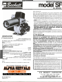
SPECIFICATIONS
P A C I T I E S MODEL SF
. . . . . . . . . . . . . . . . . . . . . . . . . . . . . . .2.50 to 5.50 gallons per hour
. . . . . . . . . . . . . . . . . . . . . . . . . . . . . .350,000 to 770.000 BTUIHR Input
See SPECIAL AIR TUBE COMBINATIONS DETAILS For
Special Firing Rates
FUELS
No. 1 or No. 2 Heating Oil (ASTM D396) Only
In Canada. No. 1 or No. 2 Furnace Oil
DIMENSIONS (Standard)
Height . . . . . . . . . . . . . . . . . . . . . . . . . . . . . . . . . . . . . . . . . . . . . . .13-518"
.
Width . . . . . . . . . . . . . . . . . . . . . . . . . . . . . . . . . . . . . . . . . . . . . . . .15-318''
.
Depth (Chassis Only) . . . . . . . . . . . . . . . . . . . . . . . . . . . . . . . . . . 8-112"
.
I
ELECTRICAL CHARACTERISTICS (See Note)
Power Supply. . . . . . . . . . . . . . . . . . . . . . . . . . . . . . .: 115 Vl60 Hz 1 PH
Operating Load. . . . . . . . . . . . . . . . . . . . . . . . . . . . . . . (Max.) 7.1 Amps
Motor.. . . . . . . . . . 114 HP 3450 RPM. N.E.M.A. "N" Flange, manual
reset. overload protected
Ignition. . . . . . . . . . . . . . . . . . 10,000 V123 ma secondary, continuous
duty, shielded transformer or solid-state ignition system
FUEL UNlT
...............................................................
Suntec, or Webster
NOTE:
50 Hertz electrical components are available on special order.
INSTALLATIONOF THE BURNER MUST BE DONE BY A QUALIFIED
INSTALLER IN ACCORDANCE WlTH REGULATIONS OF THE
NATIONAL ARE PROTECTION STANDARD FOR OIL-BURNING
EQUIPMENT, NFPA NO. 31, AND IN COMPLETE ACCORDANCE
WlTH ALL LOCAL CODES AND AUTHORITIES HAVING JURISDICTION. FOR RECOMMENDED INSTALLATION PRACTICE IN
CANADA, REFERENCE SHOULD BE MADE TO CSA STANDARD
8139.
A QUALIFIED INSTALLER IS AN INDIVIDUAL OR AGENCY WHO IS
RESPONSIBLE FOR THE INSTAL.LATION AND ADJUSTMENT OF
THE EQUIPMENT AND WHO IS PROPERLY LICENSED AND EXPERIENCED TO INSTALL OIL-BURNING EQUIPMENT IN ACCORDANCE WlTH ALL CODES AND ORDINANCES.
A properly designed chimney of adequate size and height and adeauate combustion air SUDD~Y
. - are essentials tor the best o ~ e r a t i o n
01 any heating plant.
When installing the heater and/or burner be sure t o provide adequate space for easy service and maintenance.
-
CONCEALED DAMAGE
If any damage to the burner or controls is found during unpack~ng
notify the carrier at once and file the appropriate clam
Underwriter's Laboratortes h a s c e r t ~ f ~ thls
e d burner to comply w ~ t hthe
commerc~alstandards CS75, and has listed it for use w ~ t hP 1 or u 2 fuel
011as spec~fledIn ASTM D396. State and lccal approvals are shown on
burner rating label. The burner is certif~edIn Canada by CanadIan
Standards Association (CSA). All oil burners should be ~nstalled~n
accordance with regulations of the National Fire Protection Assoc~ation pamphlet #31 and In complete accordance w ~ t hall local codes
and authorities having jurisdiction. Regulation of these author~t~es
take precedence over the general instruct~onsprov~dedIn this ~nstallation manual. For recommended installation pracllce In Canada.
reference should be made to CSA Standard B 139
1
Form 6104 BSF-R1192
Printed in U.SA
R.W. BECKETT CORPORATION
P.O. Box 1289, Elyria, Ohio 44036,
R.W. BECKETT CANADA, LTD
4 3 0 Laird, Unit 3, Guelph, Ontario, N1 G 3 x 7
IMPORTANT CAUTIONS
FZEAD BEFORE STARTING
GENERAL INFORMATION
FUEL UNITS & TUBING INSTALLATION
Burners are most commonly installed with a single stage fuel
unit. This fuel unit, when connected with a supply l ~ n eonly,
is satisfactory where the fuel supply is on a level with, or
above the burner permitting gravity flow of oil. When i t is
necessary to lift oil to the burner, a return line should be connected between the fuel unit and tank. This requires insertion
of the "by-pass" plug into the fuel unit. I f l i f t exceeds approximately 10 ft., a two-stage pump should be installed with
a return line.
When a return line is used, with either single or two-stage
pumps, air is automatically returned to the tank making the
unit self-purging.
Use of continuous runs of hcavy wall copper tubing is recommended. Always use flare fittings. Avoid use of fittings in inaccessible locations. Avoid running tubing against heating unit
and across ceiling or floor joists. If possible install under floor.
Specific informat~orlon piping, fuel unit connections, lift capabilities, and tank installat~ons is provided in the instructions
of the fuel unlt manufacturer.
COMBUSTION AIR
Burner must be installed in area with adequate fresh air available to support combust~on.
Appliances located in confined spaces: The confined space shall
be providad with two permanent openings, one near the top
of the enclosure and one near the bottom. Each openlng shall
have a free area of not less than one square inch per 1,000
Btu per hour of the total input rating of all appliances in the
enclos~lre, freely communicating with interior areas having in
i u ~ naaequatt infiltration from the outside.
WIRING
The wiring must be in accordance with the National Electric
Code and local codes and regulations.
Wiring diagrams are included in the heating cjnit installation
instructions.
CAUTION:
STAINLESS STEEL COMBUSTION CHAMBERS
The higher temperature levels produced by high-performanct
flame retention burners may exceed the temperature ratings of
stainless steel combust~onchambers and can result in chamber
burn-outs.
Where a burner upgrading IS being made in a unit with a sta~nless
steel chamber, please observe at least one of these precautions:
1. Line the Chamber w ~ t ha "wet-pac" ceramlc liner.
2. Adjust inlet alr to the burner so that the CO, level IS below
OIL
Before startlng the burner be sure fuel tank IS adequately f~lledw~th
clean No. 1 or No. 2 furnace oil. Crankcase oil, waste oil or GASOLINE
should never be used. Water, rust, or other contam~nationin the fuel
supply system will cause malfunction and premature failure of the
~nternalparts of the fuel unit
POWER CIRCUIT
Be sure that burner and controls are w~redcorrectly and that the
line switch IS properly fused (20 amp). I n Canada wiring to be
done in accordance with the Canadian Electr~calCode, Part I.
NOZZLE
Be sure that spec~fiednozzle IS Installed and that any covering
over nozzle is removed prior tostarting the burner.
NOZZLE AND ELECTRODE SETTING
Be sure nozzle and electrodes are pos~tionedas shown elsewhere
In these ~nstructlons Improper adjustment can result In oil Ip~ngementor ~ g n ~ t ~d o
~ fnf i c u l t ~ e s
AIR TUBE INSERTION
The burner head should be 'A" back from the Inside wall of the
combust~onchamber. Under no circumstances should the burner
head extend Into the combust~onchamber.
-
FUEL UNIT
UPGRADING OR CONVERSION
ATTACHING AIR TUBE COMBINATION
(CHASSIS PLAN ONLY)
If the air tube combination and oil burner chassis are packaged separately, the assembly is completed as follows:
1. Attach air tube to burner housing using four sheet metal
screws. ( I f using an adjustable burner mounting flange, first
attach flange t o air tube.) 2. Insert nozzle line electrode assembly into tube and position nozzle from head, using '2'
dimension shown elsewhere in these instructions. Check to
be certain nozzle and head are concentric. 3. Secure escutcheon plate by tightening screw at side of housing. 4. Secure nozzle line using bulkhead lock nut. When a knurled
lock nut is supplied, the recessed side is to face away from
burner housing. 5. Attach connector tube (from pump to
nozzle line). With long air tube combinations, insertion of
the nozzle line electrode assembly into the air tube is facilitated by rotating the assembly 180° from its installed
position, inserting i t partially into the air tube, and then
rotating i t back t o its proper position.
SETTING THE BURNER
Use a mounting flange or pedestal as required.
The end of the burner air tube should be 'A" back from
the inside surface of the front wall of the combustion
chamber.
Insulate around air tube to prevent overheating of tube,
nozzle and components. Make sure that insulation and
cement do not obstruct face of burner head.
Be sure that fuel unlt IS arranged for the type of 011supply system
installed
"One P~pe"or "Two P~pe" Be sure that all connectlons are t ~ g h t
Fuel units generdlly requlre manual ventlng of alr when ~ n ~ t ~ a l l y
started. Failure to vent the alr from the fuel unlt through the vent
plug prov~dedmay result In an alr lock w ~ t h ~
the
n pump that w ~ l l
prevent 011from be~ngdelivered to the nozzle See also Fuel Unlt
I\,flanufacturer's~nstructlons
LINE O I L FILTER
Use an oil filter of generous capacity for all ~nstallat~ons.
Install
inside the building between the tank shutoff valve and the burner.
For ease of servicing, locate the filter and a shut-off valve close to
the oil burner.
O I L SHUTOFF VALVE
Install approved high qual~tyshutoff valves in 011supply line in
accessible locations, one close to the tank and another close to oil
burner, but ahead of the filter. Note that some types of filters are
made with a built-in shutoff valve.
T
STARTING A N D ADJUSTMENT PROCEDURE
Caution: D o not attempt to start the burner when excess oil has
accumulated, when the furnace or boiler is full of vapour, or
when the combustion chamber is very hot.
1. Set
thermostat substantially
above room temperature.
2. Open shut-off valves in the oil supply l ~ n eto the burner.
-
HOMEOWNER INFORMATION
3. Check ~ n ~ talr
~ aadjustment.
l
Normally the bulk air band (3)
should be closed and the shutter (21 part~allyopen:
4. Close line sw~tchto start burner. I f burner does not start
immediately, re-set manual overload switches on motor and
control.
5. Vent fuel unit as soon as burner motor starts rotating. To
vent, loosen vent plug while holding an empty container
under the vent opening to catch oil which will be expelled.
Dra~nat least 112 plnt of 011from the pump then close the
n
be instantaneous with closing
vent plug. The ~ g n i t ~ oshould
the vent plug.
If the burner starts and runs but stops agaln dur~ngthe venting
operation, Walt three t o five minutes for the safety switch to cool
then re-set the manual switch and repeat the procedure until ignition IS obtained. Somet~mesafter venting is accomplished and
oil is Ignited, the fire will again go out. This probably means that
additional venting is necessary. Repeat the above venting procedure.
AIR ADJUSTMENT
Adjust air supply by loosening lock screws and moving air shutter (2)
and if necessary the bulk air band (3). Allow just sufficient air to obtain
clean combustion determined by visual inspection. Reduce air supply
until flame tips appear slightly smoky, then increase air just enough to
make the flame tips appear absolutely clean.
DRAFT CONTROL ADJUSTMENT
When the burner air supply and draft are properly adjusted the combustion chamber draft will normally be .01" - .02" WC. Larger installations may require slightly greater draft.
F
O I L SUPPLY
Do not allow the fuel tank t o run out of oil. During the summt
be sure that your fuel tank is kept full; this will prevent conder
sation of moisture on the inside surfaces of the tank.
IF YOUR TANK RUNS DRY, I T M A Y BE NECESSARY
TO MANUALLY VENT THE AIR FROM THE PUMP
AND LINES WHEN RE-STARTING THE BURNER.
-
COMBUSTION AIR SUPPLY
Your burner requires a generous amount of clean combustion a
in order to burn the fuel completely. Lack of adequate combu:
tion air may result in erratic operation of the burner or nois
combustion or fuel odors in the air. Remember your need fc
outs~deair will be greatly increased i f you have a vented dry€
in the basement or other venting fans in the home.
OILING MOTOR
Motor life will be increased by proper oiling. Use a few dropsa
non-detergent oil at both motor oil holes twice each year
FILTER
The line filter cartridge should be replaced every year t o avoi
contamination of the fuel unit and atomizing nozzle.
AREA AROUND HEATING UNIT
Should be kept clean and free of any combustible materials especially papers and oily rags.
NEVER
Burn garbage or refuse in your heating unit. Never try to ignite oi
by tossing burning papers or other material into your heater.
SERVICE INFORMATION
FINAL ADJUSTMENTS
At this point a final adjustment should be made using suitable instruments for smoke spot and C02 (or 0 2 ) measurements. Unless
otherwise specified in appliance manufacturer's instructions, the unit
should be set as follows: After allowing 10 minutes for warm up, air
should be set so that the smoke number is zero or a trace; less than
no. 1 smoke is highly desirable and should never exceed this limit.
(Note: Occasionally a new heating appliance will require longer warm
up time in order to burn clean because of the evaporation of oil
deposits on the heat exchanger and other surfaces. C02 measured in
the stack (ahead of the draft control) should be a minimum of 10% for
knocked down appliances or retrofit applications and a minimum of
12% for units with burners tested and supplied by manufacturers as a
package.
"Preventive maintenance" is the best way to avoid unnecessar)
expense and inconvenience. Have your heating system and burnel
inspected a t regular intervals by a qualified service man. I f diffi
culty occurs, follow these simple checks before calling the servicc
man.
1. Be sure there is oil i n the tank and valve is open.
2. Be sure the thermostat is set above Room Temperature.
3. Be sure main Line Switch i s "ON" and fuses are not blown.
4. Reset Safety Switch of Burner Primary Control.
5. Press Thermal Protector. Button of Burner Motor.
6. If installation i s equipped with Manual Reset Limit Control
. . . Press Reset Button.
7. If burner runs but there is no flame, fuel unit may be airbound. Follow instructions for venting fuel unit.
Tighten all locking screws after final adjustments are made.
The unit should be started and stopped several times to make sure
there are no significant rumbles or pulsations.
THE FOLLOWING INFORMATION IS IMPORTANT I N
SERVICING THE BURNER
CHECKING THE CONTROLS
Check and adjust all controls In accordance with the Control
Manufacturer's instruction sheets. Be sure the primary control
safety switch operates proper1y so that safety shutdown will occur in the event of equipment malfunction.
The operation and care of the heating system should be explained
t o the home owner, including how t o adjust the thermostat, necessity of air supply to the burner. care of the burner. and the
simple checks to make before calling for service if the burner fails
1. Burner Components: I f replacement of burner parts i s neces
sary, always use parts recommended by the manufacturer. Specif)
part number & description when ordering.
2. Nozzles: Use of the correct atomizing nozzle is very impor,
tant. I f replacement i s necessary, use the same type supplied-by
the manufacturer. Nozzle capacity and type are stamped on the
hex-portion of the nozzle body. Use extreme care in handling
nozzles t o avoid scratches or dirt that could cause leaks or affecl
the oil spray pattern.
3. Electrode Setting is important for reliable ignition of the oil.
Check to be sure setting i s in accordance with instructions provi.
ded elsewhere in this manual.
4. Fan and blower housing should be kept clean of dirt and
lint. I f heating unit is located near unvented dryer, special care
tn n n n r a t e a u n t n m a t i r a l l \ r
-,.c.*
FINAL CHECKS
Be sure air shutter and draft control are locked . . . that there is
an ample supply of fresh air t o the room in which the unit is lop cated, and there are no oil leaks.
INSTRUCTING THE HOMEOWNER
I...-, .-L..-
*L.,.*
I:-*
Am-.- --*
---*-:-* -:..
-------- :-
L..----
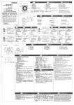
AIR TUBE COMBINATION DnAlLS
#,L8,
=
"R"
=
"S"
oAu +
5/8"
"A" + 2-7/8"
= 2-5/16"
S E E BELOW-+
ELECTRODE ADJUSTMENTS
NOTE
- ELECTRODE POSITION
MODELS
DIMENSION
ring only
AIR TUBE COMBINATION PARTS
AIR TUBE COMBINATIONS
Air Tube
Firing Range G.P.H.
Dimen.
20
25
26
27
28
33
35
36
41
42
43
44
45
46
47
AirTube . . . . . . . . . . . . . . . . . . .
Nozzle Line Fitting (Pump End) . . . . .
Lock Nut, Nozzle Line Fitting . . . . . .
Nozzle Adapter . Single . . . . . . . . . .
Electrode Clamp . . . . . . . . . . . . . .
Contact Springs (as reqd.) . . . . . . . . .
Static Plate and Nozzle Line Support
Assembly . . . . . . . . . . . . . . . . . .
Centering Spider . . . . . . . . . . . . . .
Static Plate (See A.T. Combs) ......................
Static Plate Holding Screws . . . . . . . .
Nozzle . . . . . . . . . . . . . . . . . . . .
Electrode Rod arld Tip . . . . . . . . . . .
Porcelain . . . . . . . . . . . . . . . . . . .
Electrode Rod Extension Adapter, as
reqd.
Electrode Rod Extension, as reqd. . . . .
Nozzle Line and Vent Plug . . . . . . . .
Bumer Head, (one piece head and shield)
Type F220 F310 . . . . . . . . . . . . . . .
Note
3-421
3-666
2-13
1-49s
3-241
Note
5-653
3-383
4-341
9'
13'
16'
Head
Static
Plate
I
1
1.25-2.25
SF65FO
SFSOFO
SF130FO
SF160FO
F12
244
I
I
1.75-2.75
SF65FP
SFSOFP
SF130FP
SF160FP
F22
244
I
I
1.75-3.25
SF65FD
SFSOFD
SF130FD
SF160FD
F220
None
2.5-5.5
I
I
SFSOFT
SFl30FT
SF160FT
F310
None
Note
Note
Note
Note
Note: Specify Burner model number "SF", part description;
air tube combination with air tube length (Dimension "A")
and firing rate.
NOZZLES
UNIT APPLICATIONS: When burner is supplied as an integral
component of a heater the best nozzle choice will have been
determined by extensive testing. The heater manufacturers
recommendation should be closely followed.
UPGRADING OR CONVERSION: Use 80° Solid Cone
Nozzle.
To determine
The Air Tube Length ('1 is the distance from the front of the
burner housing to the face of the burner head and/or shield.
(NOTE: Adjustable flange width - 1-118").
PARTS
/c
WHEN ORDERING PARTS
-
\
STATE BURNEU MODEL, PART DESCRIPTION AND PART NUMBER
I
REF.
1
2
3
4
4
5
6
7
9
10
11
12
DESCRIPTION
BURNER HOUSING ASSEMBLY
Burner Housing with Inlet Bell ......
End Air Shutter .....................
Bulk Air Band. ......................
Nozzle Line Escutcheon Plate - Front ...
Nozzle Line Escutcheon Plate - Rear. ...
Unit Flange or ......................
Square Plate .....................
Holding Screws (not shown) .......
Hole Plug-Wiring Box (not shown) .....
DRIVE MOTOR .....................
Motor Holding Screws ............
BLOWER WHEEL Regular.. ..........
Large (See Special Note) ..........
FLEXIBLE COUPLING . . . . . . . . . .
FUEL UNIT
Single-Stage Sundstrand "J" . . . . .
Two-Stage Sundstrand "H"
.....
Single-Stage Sundstrand "A" . . . . .
Pump Outlet Fitting . . . . . . . . . . . . . .
Pump Holding Screws (not shown) .
Connector tube assembly pump to
nozzle line ,. . . . . . . . . . . . . . . . . .
Hinge Screws. . . . . . . . . . . . . . . . . .
Holding Screws . . . . . . . . . . . . . . . .
tUse Coupling No. 2-433 With Model A Fuel Units
PART NO.
DESCRIPTION
REF
3-4!33
Air Tube Combination
Air Tube Gasket (not shown).
3-416
Adjustable Mounting Flange
5-432
Pedestal Support
5685
Extended Pedestal Kit . . . . . . . . . . . 5-606
'Specify Air Tube Combination (see overleaf)
38
39
40
3-818
3-230
3-399
#
...........
.......
........
..............
18
53488
3-215
3-819
PART
When positive firebox pressure exists, large
burner fan may be required. (See parts list)
SPECIAL NOTE:
2-139
2-364
4-82
2-288
2-383
t2-290
SUGGESTED COMBUSTION CHAMBER
DIMENSIONS - UPGRADING OR CONVERSION
Firing
Rate
(GPH)
2-396
2-393
2-591
2-256
4-82
1.25
1.50
2.00
2.50
3.00
3.50
4.00
5.00
5.50
5-394
4-217
4-292
,
,
I
Chamber Dimensions (in inches)
Round
l.D.
11
12
14
16
18
19
20
23
24
Rectangular
W
10
11
12
13
14
15
16
18
19
11
12
15
17
18
19
21
23
24
' Height
12
13
13
14
15
15
16
18
19
Floor
To
Nozzle
5-6
6-7
6-7
7-8
7-8 /1
7-8
8-9
9-10
10-11