1
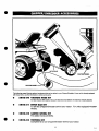
AWICCULLOCH
CHIPPER/SHREDDER
o
UK
a
OWNER’S
MANUAL
READ CAREFULLY
287
.,
m
1
WARNING: TO REDUCE THE POTENllAL FOR ANY INJURY, COMPLY WITH THE FOLLOWfNG SAFETY
INSTRUCTIONS. FAILURE TO COMPLY WfTH THE lNSTRUCTfONS MAY RESULT IN PERSONAL INJURY.
.. ..
. .
. ..
.
.
.. .
..
●
n tfre cumng mecnamsm stnf(es any fore~n otqact or n
TRAINING
your machine should stari making an unusual noise or
Read this owner’s manual carefully in its entirety before
vibration, immediately stop the engine, disconnect the
attempting to assemble or operate this machine. Be
spark plug wire from the spark plug and move it away from
completely familiar with the controls and the proper use of
the spark plug. Allow the machine to stop and take the
this machine before operating it. Keep this manual in a
following
steps:
safe place for future and regular reference or for ordering
. Insf%t for damage.
replacement parts.
Replace or repair any damaged parts.
Children must never be allowed to op”erate this
Check for any loose parts and tighten to assure continued
equipment.
safe operation.
No one should operate this unit while intoxicated or while
The engine must be kept clean of debris and other
●
taking medication that impairs the senses or reactions.
accumulations.
lWs equipment should never be operated in the vicinity of
Do not allow an accumulation of processed material to
●
children, pets or other persons.
build up in the discharge area as this will prevent proper
Never run your machine in an enclosed area as the
discharge and can restilf in kti-back from feed opening.
exhaust from the engine contains carbon monoxide,
Never place your hands or any other part of your body or
●
which is an odorless, tasteless and deadly poisonous gas.
clothing inside the feeding chamber, dis~arge chute or
Never place your hands or any part of your body or
near any moving part while the engine .is running.
clothing inside the feeding chamber, discharge. chute, or
Keep all guards and deflectors in p!ace and in good
●
near any moving part while the machine or engine is
working condition to assure continued safe operation.
running.
Always stand clear of the discharge area when operating
●
H it is necessary for any reason to inspect or repair the
this machine.
feeding chambers or any part of the machine where a
Keep your face and body back from the feed opening to
●
moving part can come in contact with your body .or
avoid accidental bounce back of any material.
clothing, stop the machine, allow it to cool, disconnect the
●
Do not over-reach. Keep proper balance and footing at all
spark plug wire from the spark plug and move it away from
the spark plug before attempting such inspection or
times.
repair.
The engine governor settings on your machine must not
●
be altered, changed, or tampered with. The governor
PREPARATION
controls
the maximum safe: operating speeds and
Wear safety goggles, work gloves and shoes while
protects
the
engine and all rnovmg parts from damage
operating the chipper/shredder.
Do not wear loose
caused
by
over-speed.
Authorized service personnel
cbthing or jewelry.
should perform these adjustments if a problem exist.
Operate chipper/shredder only on a level surface.
Do not transport machine while engine is running.
●
Do not operate the chipper/shredder on a paved or gravel
Do not operate engine if air cleaner or cover directly over
●
surface.
carburetor air :intake is removed, except for adjustment.
Before starting the chipper/shredder,
check that all
Removal,of stih~rts
could create a fire hazard.
screws, nuts, bolts and all other fasteners are properly
ff
chipperlshredder
becomes
clogged the operator must
●
secured. Replace all damaged or unreadable warning
shut-off
engine,
and
disconnect
SPSAplug before clearing
and operating decals.
debris.
Check fuel level before starting engine. Gasoline is highly
flammable; handle with care. Use only an approved
container.
Do not fill fuel tank indoors, when engine is running, or
until engine is allowed to cool. Do not smoke.
Reinstall fuel cap on tank and fuel container. Wipe the unit
clean of any spilled fuel.
MAINTENANCE AND STORAGE
●
oPERAmoN
Before starting the machine, operators shall make certain
that the cutting chamber is empty.
When feeding material into this equipment, be extremely
careful that pieces of metal, rocks, bottles, cans or other
foreign objects are not included. Personal injury or
damage to the machine could result.
●
●
When this equipment is stoppad for servicing, inspection,
storage or to change an accessory, make sure the spark
plug wire is disconnected from the spark plug and moved
away from the spark plug. The machine should be
allowed to cool down before making such inspection,
adjustments, service, etc. Maintain your machine with
care and keep it clean for the best and continued safe
operation. Authorized service shall be sought if a problem
exists.
Do not use flammable solutions to clean the air filter.
When not in use, your machine should be stored out of
the reach of children. Keep where gasoline fumes will not
reach an open flame or spark. For long periods of storage,
refer to the “Storage- secti?n of this manual.
INING: This unit is equipped with an internal combustion engine and should not be used on or near any unimproved foreskovered, brushred or grass~vered
fand unless the engine’s exhaust system is equipped with a spark arrester
meeting applicable local or state laws (if any)
@rk arrester is used, it should be maintained in effecdve workhg order by the operator.
e ~te of CStfofia the above is required by law (Section 4442 of the Cafifomia Pubfk Resources Coda). other states may have similar iaws
ml laws appfy on federal lands. A spark amester for the mufffer is available through your nearest engine authorized service dealer.
288
D
SAFETVRULES ..............................................................2
TABLE OF CONTENTS .................................................3
ASSEMBLY ..................................................................4-5
OPERATION ................................................................8-8
MAINTENANCE .............................................................9
STORAGE .....................................................................10
.................................. 11-13
SERVICE&ADJUSTMENTS
TROUBLESHOOTING .................................................
““
14
REPAIRPARTS .......................................................15-23
ACCESSORIES ......................................................24-29
CONTENTS OF SHIPPING
TOOLS REQUIRED FOR ASSEMBLY:
CARTON:
1 - Chipper/Shreddercompletely assern~ed exceptforchipper
chute and shredder hopper
“
1 - Shredder hopper, handle and guard assembly
1- Chipper chute assembly
1 - Deflector
1 - Parts Bag Containing:
1 - Owners’ Manual
1 - Engine Manual
1 - Warranty-Cwd’
~
10 - Patch Loc 1/4-20x.50 One Way Screws %%oZ55
8 - Flatwashers .281x .~x .085 ~2tis.qz
4 - Nuts 1/4-20 REGHEX Center lock i @L
1 - %fety Goggles ~z7 ‘7~7
1 - Collector Bag’ zz o 37ti
1 - Debris Tamper
l-Regular Screwdriver
1-1/2” Wrench
1-1/2’ Socket
1-Ratchet Wrench W/extension
NOTE Tools required will depend on unit Purchased.
la
CONTENTS OF PARTS BAG
289
—
DANGER
A
●
Assemble six(6) l/4-20x .50screws, pm,vided in parts bag,
through afignsd holes. Do not tighten.
“”
““
●
Position Hopper in position level with the unit and tighten all
six (6) screws seourely.
There are rotating cutting blades inside the Chipper/
Shredder housing that will cause serious injury. DO
NOToperatemachlns unless ChlpperChuteand Shredder Hopper are seourely installed.
●
J~P 1: UNPACKING AND CHECKING
CONTENTS
Locate and remove Chipper Chute/Shredder
assembly and debrii tamper from carton.
Hopper
Locate and remove parts bag.
Cut all four corners of carton from top to bottom and lay flat.
Remove bracket from supportand cut nylon ties from axle.
Pull the Chipper/Shredder off of the pallet.
Properfy dispose of discarded c&ton and pallet.
Compare contents with the contents of parts bag. If any
parts are missing or damaged, corrtaot your local service
dealer or call for factory service.
.$TEP 2: INSTALL SHREDDER HOPPER
Rotate Shredder/1-foppsr tube upward to latched position.
~
With Shredder Hopper handle (iem B) pointing away from
the engine and the rectangular opening facing upward,
positiintheround opening of the Shredder Hopper (item A)
over the round steel chute tube (item D) (See FIG. 2ASSY).
STEP 3: INSTALL CHIPPER CHUTE
●
Remove flatwashers and locking nuts (iem B) from the
three (3) threadad studs (See FIG. 3-ASSY).
.
Positiin Chipper. Chute assembly (item A) in opening in
housing and over the three (3) threaded sttids. Place vshapsd bottom lip of Chipper Chute into opening first and
raise Chipper Chute until remaining two (2) studs are
through the top holes.
.. ●
Assem~efletwashersand locking nutstothree (3)threaded
studs and f&ten securely.
Align top hole in the ShredderHopperneck with the top hole
in the steal chute tube.
290
c)
STEP 4: INSTALL DISCHARGE
DEFLECTOR
●
“Position discharge deflector (item C) as shown
iassY.
.
Attach deflector to shredder housing using the four (4) l/420 x .50 one-way screws (item D), eight (8) fiatwashers
(iem E), and four(4) locknuts (item F). (See FIG. 4-ASSY)
●
Tighten locknuts securely.
in
FIG. 4-
,4
STEP 5: ASSEMBLY OF COLLECTOR BAG
The Chipper/Shreddercomes equipped with one of two types of
collector bag to catch the shredded material.
To atta~h the bag, place the opening of the bag around the
discharge opening (on units having a chute deflector, pull
the bag overthe deflector) until the drawstring is positioned
behind upper and lower tabs on housing. Depress the
plunger on the drawstring lock and pull on the drawstring
until the bag is tight around the discharge opening. Release
plunger to retain drawstring and bag in position. See FfG.
5-ASSY.
The Chipper/Shredder may be operated without collector
bag installed. When operating without bag, stay dear of
discharge opening and do not allow material to collect and
restrict discharge of material.
5
.-.
.
,,.,
,,.,
..291
.-
,c)
\:-,.
●
<NOW YOUR CIMPPER-SHREDDER
WAOTHIS OWNER’S MANUALAND SAFETY RULES
hnpare the illustrations with yourchippar-shradderto
his manual for future reference.
MEEK
BEFORE OPERATING YOUR CHIPPER-SHREDDER.
familiarize yoursetf with the Iocat”mriof varkius controls and adjustments. Save
ANSI SAFETY STANDARDS
Chipper-Shredders conform to the safety standards of the American National Standards Institute.
3PERAllNG CONTROLS
SEE FIGe 1 OP)
(D) SHREDDER HOPPER -Used for shredding small branches
and other small debris.
(E) SHREDDER HOPPER RELEASE KNOB -Releases ShradderHopparto rotatadtogroundpositiinforeasy rakingof leaves
and other debris into the hopper.
(F) STARTER HANDLE - Used to manuallystafi the engine.
:) CHIPPER CHUTE- Usad for chippingbranches
2) COLLECTOR BAG- Used to collect all chipped, shredded
:‘ vacuumed debris for easy disposaf.
C) ENGINE CONTROLS - Throttle and Choke controls are
xatad here. (see engine manualfor ind”widual controls)
*ORE
USING YOUR CHIPPER-SHREDDER,
AGAIN REFER TO THE “SAFETY RULES
XGE 2 OF THIS MANUAL. ALWAYS BE CAREFUL.
AS SHOWN ON
~xlmum noise level measured in a distance of Im from shredder and 1.6m above ground = 97db(A) (as per
N 4S63!5).
The operation of any chipper-shredder can result in foreign objects being thrown into the eyes,
which can resuft in severe eye damage. Always wear safety glasses or eye shields while chipping
or shredding, or performing any adjustments or repairs. We recommend Wide Vision Safety Mask
for over spectacles or standard glasses.
h
6
.
.
.
.-
... . .
..:.
..:
292
—
HOW TO USE YOUR
CH9PPER-SHREDDER:
BEFORE STARTING
1.
Place the shredder on a firm, level surface.
2.
Service engine with gasoline and oil as instructed in the
separate engine manual packed with your shredder.
3.
Insure spark plug wire is attached to spark plug.
fA
DANGER
I
A
A“
A
WARNING
A
.
THE CHIPPEWSHREDDER IS SHIPPED WITHOUT
GASOUNEIN THE FUEL TANK AND VERY LlllLE OIL
IN THE ENGINE CRANKCASE. DO NOT OPERATE
ENGINE U.~L CRANKCASE HAS BEEN HUED WITH
OIL AS SPECIFfED IN THE ENGINE MANUAL PROVIDED WfTH THE MACHINE.
●
Leaves and small branches can be fed into the Hopper
assembly when it is in the raised positiin (See FfG. 2-OP).
If it becomes necessary to push material into the Chipper/
Shredder, use the suppfied debris tamper - NOT YOUR
●
TO START ENGIN&
●
A-
DANGER
THE CHIPPER-SHREDDER DISCHARGESMATERIALS
WITH CONSIDERABLE VELOCITY. KEEPAWAYFROM
THEAREAAROUND THE DISCHARGE ALWAYS STOP
THE ENGINE AND DISCONNECT THE SPARK PLUG
WfRE WHEN REMOVING OR AITACHING THE BAG
WHEN CHANGING CONTAINERS OR WHEN REMOVING THE SHREDDED MATERIAL. WEAR SAFETY
GLASSES AND GLOVES WHENEVER USING YOUR
CHIPPER-SHREDDER
BE SURE NO ONE OTHER THAN THE OPERATOR IS
STANDING NEAR THE CHIPPER-SHREDDER WHILE
STARTING OR OPERATING.
r
..
Chipper/Shredder is designed for three (3) different methods of operation.
The
A.
A’
DANGER
.
●
Insure spark plug wire and rubber boot is attached to spark
plug (See EngineManual).
●
Turn fuel shutdf valve to ‘ON” position (if so equipped)
(seeEngine Manual).
ANY ATTEMPT TO PUSH MATERIAL WITH ANYTHfNG
OTHER THAN THE DEBRfS TAMPER CAN RESULT IN
PERSONAL INJURY AND/OR MACHINE DAMAGE.
●
Push stop switch to “ON” position (if so equipped).
+
●
Move choke control lever to “CHOKIVFULL
positiin. (See Engine Manual)
●
Move throttle control lever to ‘FAST/ON/RUN” positiin.
●
Grasp starter handle (See Engine Manual) and pull rope
out slowly until engine reaches start of compression cycle
(rope willpullslightly harderatthispoint. Letlhe rope rewind
slowly.
●
Pull the rope with a rapid, continuous, full arm stroke. Keep
a firm grip on start handle. Let rope rewind slowly. DO NOT
let starter handle snap back against starter.
●
Repeat preceding two (2) instructions until engine fires.
When engine starts, move choke lever on engine halfway
between ‘CHOKE/FULLCHOKE” and“RUN/NO CHOKE”.
4
CHOKE”
Move throttle control to idle positiin for a few minutes to
allow engine to warm-up. When engine is warm move
choke lever to “RUN positiin.
NOTE In orderto idle smoothly, anew engine may require three
(3) to five (5) minutes running above slow idle speed. Idle speed
has been adjusted to be correct after this break-in period.
TO STOP ENG9NE:
●
●
Move throttle control lever to *’OFF/STOP/SLOW position.
(See Engine Manual)
●
Push stop switch to “OFF position (if so equipped).
●
Do not choke carburetor to stop engine. Backfire or engine
damage may result if choke is used to stop engine.
NOTE: Close fuel shutoff valve (if so equipped) when transporting
or not operating Chipper/Shredder, to prevent fuel leakage.
;.,
..:
;.,,..
;.,’.
:,:.
‘.: ,. :::
...
. ... .
,., .,..-.. .
,:.
293
-.
A
r
WARNING
DANGER
A
MAKE CERTAIN THE CHIPPER CHUTE GUARD IS IN
PLACE. SHOULD THE CHIPPER CHUTE GUARD BECOME WORN OR TORN, REPLACE BEFORE CONTINUING USE.
DO NOT DEPOSIT MATERIAL LARGER THAN 1/2” DlAMETER IN THE HOPPER ASSEMBLY. ANY MATERIAL
HEAVIER THAN 1/2” SHOULD BE FED INTO THE CHIPPER CHUTE.
I
I
I
A
●
Leaves and small twigs can be raked into the Hopper
assemblyi when the Hopper assembly is rotated to the
ground. Small branches can also be fed into the Hopper
assembly in this position (See FIG. 3-OP).
Bulky material, such as stalks or heavy branches (anything
over 1/2” diameter, up to 3“ in diameter), should be fed into
the Chipper chute (See flG 5-OP).
For best performance, it isimportanttokeepthe shredding blade
and the chipper blade sharp. Refer to service and adjustment
section, pages 12, 13. If the composition of the material being
discharged changes (becomes stringy, etc.) or if the rate at
which the material feeds in slows down considerably, it is likely
that the shredding blade and/or Chipper blade is dull and need
to be sharpened or replaced.
●
Torotatethe Hopper assembly, use one (1) hand to pull the
Hopper release knob out until the Hopper assembly is free
to move (See FIG. 4-OP). Rotate the Hopper assembly to
the right (while holding the Hopper release knob) until the
edge contacts the ground.
8
,.
,::.
..,-.. ...
294
DANGER
To remove gasoline, run engine “until
tankisempty
andengine
stops. if you do not want to remove gwdine,a gasstabilizer
such as STA-BIL may be added to any gasoline left in the tank
to minimize gum deposits and ac”ds. If thetankis almost empty,
mixstabifiierwith fresh gasoline in aseparatecontainerand add
some to the tank. Always follow instructionson stsibiiizer
container.Then run engine at feast 10 minutes after etabfIizer is added to allow mixture to reach carburetor. Store
chipper-shredder in safe piace. See warning above.
A
NEVERSTOREYOUR CHIPPER-SHREDDER INDOORS
OR IN AN ENCLOSED, POORLY VENTILATED AREA
IF GASOUNE REMAINS IN THE TANK. FUMES MAY
REACH AN OPEN FiAM~ SPARK OR PILOT UGHT
FROM A FURNACEj WATER HEATER, CLOTHES
DRYER, CIGAREITEj ETC.
w
The following steps should beteken to prepare yourshredderfor
storage.
TOprevent engine damage if chipper-shredder is not used for
awe than 30 days, follow the steps below.
NOT12 GASOLINE MUST BE REMOVED OR TREATED TO
PREVENT GUM DEPOSITS FROM FORMING IN THE TANK,
FILTER, HOSE AND CARBURETOR DURING STORAGE.
AEODURINGSTORAGE, ALCOHOL-BLENDED GASOLINE
THAT USES ETHANOL OR METHANOL (SOMETIMES
CALLEDGASOHOL) ATIRACTS WATER. IT ACTS ON THE
GASOLINE TO FORM ACIDS WHICH DAMAGE THE ENGINE.
.
Clean unit thorougitly, including engine.
●
Refer to engine manual for correct engine storage
instruct”mns.”
●
Carefully inspect unit and repiace any worn, damaged, or
missing parts and tghten any ioose fasteners
●
if storing in an unventilated or metal storage shed, coat
metal parts with a ~ght oil or sifiine to prevent rusting.
●
Store Chipper/Shredder in a dry, clean are% out of the
reach of children.
●
. .
..
.—.
—.—
.— —-—.
10
:’:
!
2,6:
.,
‘. :,”
~~
A “
A
DANGER
ALWAYS STOP ENGINE AND DISCONNECT SPARK
PLUG WIREANDMOVEITAWAY FROM SPARK PLUG
BEFORE PERFORMING ANY ADJUSTMENTS OR REPAIRS.
.
‘Remove the Made, using a 3/16- alle.rrwvrench(its’ 6) on
the outside of the bfade and 1/2- wren~ (iiefiC$ on the
impeller assembfy ([email protected],the housing) (See ,HGH-SERV
&ADJ).
“’”,”,
●
Repface or sharperr ‘blade. Re~errible
in reverse order
making. certain to install the “,bladb with the s@rp edge
faang away fromtheimpellerassembij and~~ngtoward
the sfot in the impeller assembfy. Tmhten Ioclmutssecurefy
(i using a torque wrench, tighten @mrts to 20 ft-lbs). -
WHEN CLEANIN~ REPAIRfNG OR INSPECTING YOUR
CHIPPEFUSHREDDER MAKE CERTAIN ALL MOVING
PARTS HAVE STOPPED.
TO REDUCE THE RISK OF INJURY, ALWAYS WEAR
HEAVY GLOVES WHEN HANDUNG THE CUITING
BLADES. THE CUTllNG EDGES ARE SHARP AND
CAN CAUSE SEVERE INJURY.
s
.6.
,,
,: .?o
d
Sharpening
OR REPLACING
CHIPPER BLADES:
Over a perkxf of time, the cutting blade will dull. Sharpen or
replace the blade when the chipper no Iongercuts as efficiently
as’when new.
●
Discard a cracked or severely nicked blade because it
could break apart and cause personal injury.
●
Sharpen abladethat isdullorthat has only minor nicks. The
blade is made from tempered steel and is extremely hard do not attempt to sharpen with a hand file. We recommend
that youtakethebladeto aprofessiortal sharpening service
for proper sharpening. All grinding must be done flat and
uniform along the beveled edge oniy, being sure to maintain
the original 45° cutting angle.
TO REMOVE AND INSTALL THE
CHIPPER BLADE:
Disconnect epa~ plug wire and move it away from spark
plug.
Remove the Chipper chute by removing three(3) hex nuts
and washers (iems B). A 1/2” socket with extension is
required (See FIG.-3 ASSY).
Rotatethe Hopparassemblytotheground
3-OP.
as shown in FIG.
Remove the three(3) hex focknuts (iem A) and flatwashers
(iem B) from the housing studserts and carefully separate
the Hopper assembly from the remainder of the unit (See
FIG. 2-SERV. & ADJ.)
Remove the three (3) bushings (item C) and stationary
plate (iem D). (See FIG. 2-SERV. & ADJ) NOTE: When
reassembling, make certain the opening of the stationary
plate is toward the bottom of the unit and the offset, is facing
toward the impeller assembly.~
Rotate the impeller assembly by hand until you locate the
Chipper blade in the Chipper chute ~pening.
Prevent the impeller assembly from turning in a
counterclockwise direction by wedging a block of wood
between one of the fan blades and the wall of the housing
or, insert a thick, hardwood dowel (item A) through the slot
below the blade and into the Chipper chute opening in the
wall of the housing. (See FIG. 1-SERV & ADJ).
.
,..
--
,..
RMRSING,
SHARPENING, OR
REPLACING SHREDDER BLAD~
●
The shredding blade is reversible and can be reversed
before any sharpening shoufd need to be pwformed.
●
After both sides of the blade have become dull, nicked, etc.
to the point of reduang performance, the blade needs to be
sharpened orreplaced.
TO REMOVE AND INSTALL
SHREDDING BLADB
-
Disconnect spark plug wire and move it away from spark
plug.
Rotate the Hopperassemblytotheground
3-OP.
asshownin flG
Remove the three (3) hex locknuts (iem A) and flatwashers
(iem B)from the housing studserts and carefully separate
the Hopper assembly from the remainder of the unit (See
FIG. 2- SERV & ADJ.).
Remo#e the three (3) bushings (item C) and stationary
plate”(item f)) (See FIG. 2- SERV.& ADJ.) (NOTE: When
reassembling, make certain the opening of the stationary
plate istowardthe bottom of the unit and the offset, is faang
toward the impeller assembly).
Prevent the impeller assem,bly from turning in a
counterclockwise direction by wedging a block of wood
between one of the fan blades and the wall of the housing.
.
..
297
.,0
●
Starttheengirk and Iistenftir.anyunusual noise orviiration
~ that could signal im~rope~ installation of the shrei@~ng
~l~e or impeller assern~.nfi:there is an unusudpbiqep
vibration, stbp the engine imm@latdy ~d call the factory
or contact your tor@ authorized serv.~ ,dealer. Do “not
attempt to operate the machine until the problem has been
corrected.
Aa
m
Removethe im@dleras$embly(See flG.3+E~
& ADJ)
byremovingthecenterbo~, lockwasher,”a@springwasher
(NOTE When reassembling, make ceitkin”the raised side
of the spring washeifatis the bolt head).
OTt5 Use caution when removing the impeller assembly from
Ie houiiing.
.,.’
I
Laythe impeller assembly on a solid, level service with the
shreddi~ blade facing up.
I
I
Using twp (2) 1/2” wrenches, remcwe theshredding blade
from impeller assembly by removing the blade retaining
bolts, ffatwashersand locknuts(SEE FfG.3-SERV&ADJ).
When sharpening the blade, follow the original angle of
grind as a guide. ft is extremely important that each cutting
*e
recetis an equal amount of grinding to prevent an
unbalanced bladq. An unbalanced blade will cause
excessive vibration when rotating at high speeds and may.
cause damage to the unit.
The blade can be tested for ~iaWe by balancigg it on a
round shaft screwdriver or nail. Remove metal from the
heavy side until it is balanced evenly (SEE FIG. 4-SERV &
ADJ).
When reassembling the shredding blade, tghten the bfade
retaining bolt nuts to 20 ft-lbs., or lacking torque wrench,
tighten securely.
Sefore reinstalling impeller housing, thoroughly clean the
housing chamber and the engine crankshaft. Apply a
coating of fresh, good quahhygeneral purpose grease to the
crankshaft.
FLAILS
Reinstall the key in the crankshaft keyway.
The flails are permanently attached and, under normal conditions, made to last the Me of the unit. Shoukf the flails become
damaged, cracked or broken, contact your qearest service
dealer for replacement.
Afiinthekeywayinthe impellerassembly with thecrankshaft
key and carefully slide the impeller onto the crankshaft.
Tiihten the impeller assembly centerbolt to-45-50 ft-lbs.
(SrlggsEnglnes); 55-60 ft-lbs. (Tecumseh Engines); or
lacking torque wrench, tighten securely.
Reassemble remainder of unit.
12
a
/-. ,
r
{,
.,:-/,
?.
.)
.’!.T.-;:.:
,.: .,,
..-: :, .. ... .. . .. . ...
. .
.
.:.,,.,
:.!,
.. .
. ...
. .
.. . ...
.
.,,
.
.:,:!i:~;;c,-,..:;:~..,.
!,
..
<
●
-
.
. .../
CARBURETOR ADJUSTMENT
ENGINE SPEED
Your engine speed has been fa~ory set. Do not attempt to
increase engine speed or it may result in unit damage or
personal injury. ff you befieve the engine is running too fast or
too slow, take your Chipper/Shredder to the nearest Service
Center for repair and adjustment.
A
DANGER
I
IF ANY ADJUSTMENTS ARE MADE TO THE ENGINE
WHILE THE ENGINE IS RUNNING (E.G. CARBURETOR), KEEP CLEAR OF ALL MOVING PARTS. BE
CAREFUL OF HEATED SURFACES AND MUFFLER.
Minorcarburetoradiustment may bereauiredtocommnsatefor
differences in fuel, ~emperature; altitude or bad.
‘
NOTE A di~y air cleaner will cause engine to run rough. Be
certain air cleaner is clean and attached to the csrburetorbefore
adjusting carburetor. Do,not make un-necesssry adjustments.
Factory settings are satisfactory for most applications and
condfi”bms. If adjustment is needed, refertothe separate engine
manual packed with your unit.
a
regular aarvice
SERVICE DATES
SCHEDULE
SERVflCE RECORD
FillIn dates as you complete
After
First
5
Hours
>heck Fuel
Before
Each
Use
4
Every
25
Hours
Every
50
Hours
Beginning Each
Season
,“
4
)rain Fuel
\l
,1
>heck Engine Oil Level
lhange Engine Oil
~
d
4
~
Xl Pivot Points
service Ah “Cleaner
4
Y’
,/
~eplace Fuel Filier
>Iean Engine Cylinder Fins
~eplace or Clean Spark Plug
j
d
-
+
Spark Arrester Muffler
●
Before
Storage
~
,i
✌✌
The Service Recommendations Chart is suDolied to assist the oDerator in rxomr maintenance of the chiooer-shredder. This is onlv a
check list; instructions will be found in the Maintenance and Sehice Adjustment sections of this manual.’
13
299
..-.
.-.
,..
.
. in
,....,,
:
PROBLEM
POSSfBLE CAUSE (S)
I
Engine fails to start
1.
2.
3.
4.
Fuel tank empty, or stale fuel.
Sparkplug wire disconnected.
Faufty sparkplug.
Dirly fuel filter. (is so equipped)
“-1.
2.
3.
4.
I
Loss of power;
operation erratically
1.
2.
3.
4.
Sparkplug wire loose.
Unit running on CHOKE
Blocked fuel line or stafe fuel.
Water or dirt in fuel system.
1.
2.
3.
4.
,
~
Corrective
I
ACTfON
Fill tank wnh clean, fresh fuel. “”
Connect wire to spark pfug.
Clean, adjust gap or replace.
Replace fuel filter. (ii so equipped)
-
5. Carburetor out of adjustment.
6. Dirty air cleaner.
connect and tigMen spark plug wire.
Move choke lever to.OFF position.
Clean fuel line; fill tank with dean fresh gasolim
Disconnect fuel line at carburetor to drain fuel
tank. Refill with fresh fuel.
5. Adjust carburetor or contact your Service Cente[
6. Clean air filter.
Engine overheats
1. Carburetor not adjusted properly.
2. Engine oil level low.
3. Engine cooling fins blocked.
1. Adjust carburetor or contact your Service Centel
2. Fill crankcase with proper oil.
3. Clear debris from fins.
Too much vibration
1. Loose parts or damaged impeller
1. Stop engine immediately and disconnect spark
plug wire. Tighten all bolts and nuts. Make all
necessary repairs. ff vibration continues, have
unit service by a Service Center.
Unfts doas not dischargf
1. Discharge chute clogged.
1. Stop engine immediately and disconnect spark
plug wire. Clean inside of blower housing. See
Service/Adjustments section of this manual.
2. Stop engine immediately and disconnect spark
plug wire. Remove fodged objecL
I
2. Foreign object Iod@f in impeller,
~OT& For repairs beyond the minor adjuskents
listed above, please contact your-nearest service Center.
..
..
●
14
.-
301J-
..
KEY #
PART #
10
12
14
180085
996407
15
17
56845
305562
18
327225
18-4
18-6
18-8
18-10
319661
323328
120638
18-12
20
22
24
414072
323839
319660
319659
26
325463
DESCRl~ON
ENGINE, 8 HP B&S
(SEE ENGINE MANUAL)
SCREW, 5/16 -18X 1.75 IN.
WASHER, FLAT
.328 X .75X .077
NUT, 5/1 6-18 REGHCTRLK
KEY, SQUARE
.250SQX2.12LG
ASSEMBLY, FLAIL
BALANCING
NON-SERVICEABLE
BLADE, CHIPPER
SCREW, 5/1 6-24 X 1.00
WASHER, HVSPTLK. ‘
.328 X .60X .09
NUT, 5/1 6-24 REGHCTRLK
PIN, FLAIL .50 X 2.81
FLAIL
SPACER, SPEC
.515 x 1.00x .700
SPACER, SLEEVE
.515 x 1.00x .700
(EY #
PART #
r
56113
29
330517
30
32
329416
319710
34
36
180085
996407
38
2307
40
42
44
56845
326986
120382
46
2483
50
327426-88<
I DESCRIPTION
WASHER, FIAT
.50 X .94X .06
FLATWASHER,
515 x 1.00x .030
RIVET, OVSET.188 X 1.094
BLADE, ROTARY SHREDDER
SCREW, 5/16-18 X 1.75
WASHER, FLAT
.328 X .75X .077
WASHER, FLAT
.375 X .88X .125
NUT, 5/1 6-18 REGHCTRLK
SCREW, 3/8-20 X 2.25 IN.
WASHER, REGSPTLK
.393 x .68x .10
VV:~S+vE~,.391DX1.25DX.07
ENGINE MOUNT/AXLE
ASSEMBLY
I
33062S-330779
15
...
.
,,
“i~.
i
;
/
... .
,,
-----
.
.
. ..
;,..i..$
,GINE 8HP
. .
“f
’’:.”‘“m
@----l!
REF.
ENGINE
KEY #
PART #
60.
62
330088-853
t 20386
64
1498.
’66
1501
68
E
74
57220
330780-853
180077
120386
76
1498
80
82
330781
330782
330571
330289
DESCRIPTION
“
PLATE, TANK BRACKET
WASHER, FLAT .312X
.73X.065
NUT, 5/16-18
REGHEXCTRLK ‘“
WASHER, FIAT .203X
.56X,040
SCREW, #12 X .50
BRACKET, GAS TANK
SCREW, 5/16-1 8X .751N
WASHER, FIAT
.312x .73x .065
NUT; 5/16-18
REGHEXCTRLK
GAS’TANK ASSY
SCREW, GAS TANK
OWNER’S MANUAL, ENG
OWNER’S MANUAL, FFUGER
330625-330779A
,
1
I
16
.
302
.,-
.
.
.
.. . . .. ..,...
II
PART#
KEY #
88.
’90
92
I
305508
326863
323326
II
. . ., . . .
..
..4 ..
DESCRIPTION
TIRE & RIM SEPU 12X3
SPACER, SLEV. 640X1 .00X.688
NUT, PUSH ON 5/8”
327212-32381 5A
KEY #
120
125
130
134
136
PART#
328341
330205
325856
330166
326992
DESCRIPllON
HOPPER, DEBRIS
SCREW, 1/4-20X .5o
HANDLE, HOPPER
GUARD, WIRE HOPPER
RIVET POP .187DIAX .562LG
330216-330217
17
.-
.. :::,
,.
::,
303
.. . .
FLAIL HOUSIt4G ASSEMBLY
m
A
.
.9
KEY #
x
212
214
216
218
220
222
223
225
228
232
234
236
237
238
240
242
244
246
~
PART#
330108-889
181595
120638
180077
996407
1498
326833
326992
1501
330213-853
180016
120392
1502
996407
1498
330049-889
330205
120392
1502
~
DESCRIPTION
FLAIL HOUSING, ASSEMBLY
SCREW, 5/16-24 X .75
WASHER, HVSPTLK .328X .60X .09
SCREW, 5/16-18 X .75
FlATWASHER, .328X .75 k .077
NUT, 5/16-18 REGHEXCTRLK
SHROUD COVER, FLAIL
RIVET, POP .187 DIA X .562 LG
FLATWASHER, .203x.56x.040
BAFFLE & STUDS ASSY,
SCREW, l/4-20X .50
WASHER, FLAT .281X .63X .065
NUT, 1/4:20 REGHEXCTRLK
WASHER, FLAT ;328 X .75 X .077
NUT, 5/16-1 8 REGHEXCTRLK
DEFLECTOR, ASSY(EXPORT)
SCREW, 1/4-20X .50
WASHER, FLAT .281X .63X .065
NUT, 1/4-20 REGHEXCTRLK
330210-33021 1A
18
. .._
..
::.
.:,
..:;:.
.304
2HIP c21iuiE ASSEMBLY
,., . .
.:
.,.
..
KEY #
410
414
416
420
422
430
431
432
PART#
.31 98*-889
986407
.1498
323333
309235
326834
1501.
DESCRIPTION
‘- “
““
CHUTE, ASSEMBLY CHIPPER
WASHER FLAT .328 X .75X .077
NUT, 5/16-18 REGHEXCTRLK
GUARD, CHIPPER CHUTE
FASTENER, RATCHET
HOOD, CHIP CHUTE
RIVET, POP (NON SERVICEABLE)
(SEE NOTE BELOW)
WASHEf+ FIAT .203X .56X .040
L
-6C7.. aaaa.nm
MOTE: KEY 431, RIVET ISA NON-SERV1CEA8LE
ITEM. ORDER 5S686 SCREW, 1 /4-20
X .63
ELTSRMA, 57626 PLATWASHER, .281 Xl .25 X.06,
S 1335 NUT 1 /4-20
WBEI WHIZ-U( AS SHOWI
N INSET TO REPLACE TNE RIVET19
... . .
.,,,.
.
,..
.. . .
:.
.:::
305
. . . . ........
CHUTE TUBE & PLATE ASSEMBLY
.’
<EY #
PART# .
510
520
522
524
526
528
530
532
534
536
538
540
542
544
322864-889
322777-889
323338
322738
996416
1499
322776-889
324197
323932
46763
414106
322741
322739
325083
DESCRIPTION
PLATE, STATION ROTATE CHUTE
TUBE& PLATE,’ ASSEMBLY CHUTE
SEAL, SHREDDER CHUTE
BUSHING. ROTATE CHUTE
WASHER, FLAT .391 X 1.00X .125
NUT, 3/8-16 REGHCTRLK
RETAINER COVER
FITTING, LUB-PRESS FIT
RETAINER, SPRING
RIVET, POP .187DIAX.450LG
FLATWASHER, .188X.38X.040
RELEASE, HANDLE
SPRING, COMPRESSION
KNOB, .75 DIA.
. . . . .. . . . . . . .
20
.
~=, )
DECALS
., ..,.
NSETA
KEY #
PART#
600
601
602
608
620
628
629
630
330176
330450
330451
330177
402261
402260
330178
330452
DESCRIPTION
REFERENCE ONLY
REFERENCE ONLY ~
REFERENCE ONLY
DECAL, EXPORT, CAUTION GER
DECAL, EXPORT, CAUTION ENG/FR
DECAL, OPERATOR ENG/FR
DECAL, OPERATOR GER
DECAL HEARING PROTECTION
DECAL, EYE PROTECTION
DECAL, EXPORT, DANGERGER
DECAL, EXPORT, DANGER ENG/FR
i
330802-3228310
21
,.”:
307
rOOIS ASSEMBLY
●
●
KEY #
I
710
712
PART#
I
327243
327789
,
DESCRIPTION
I
TAMPER, CHIP/SHRED
GOGGLES, VENTED
m
1
326090B-328244A
●
..
308
.
.—
;,.,
“a
!
BAG COLLECTOR ASSEMBLY
. ,,
,,
-’ --
........-7
.
●
:0
.@
I
KEY #l
810
I
PART#
320376
f
DESCRIPTION
I
I
BAG, COLLECTOR, DRAWSTRING
32#91A-3282@B
23
.-
..“
“’ .309
CASTER WHEEL ASSEMBLY
::
g-d
.1
.,
.
KEY #
PART #
820
327153-889
822
824
828
830
831
832
833
834
836
838
840
842
844
845
846
848
850
25840
56845
327106
327156-889
325892
706
40677
53806
326863
302270
327874
327875
327157
120396
328713
996416
1499
L
... ..
DESCRIPTION
CASTER WHEEL SUPPORT
FRAME ASSY
WASHER, SPRING
NUT, 5/16-18 REGHCTRLK
PLUG, TUBE CLOSURE 1.25 DIA
CASTER WHEEL YOKE ASSY
WASHER, PLASTIC, .06X .625X 1.5
ZERK, GREASE F17TING
WASHER, FIAT .640X 1.25 X.06
WASHER, FLAT .632X 1.11 X.06
SPACER, SLEV .640X 1.00X .688
RING, RETEX
WHEEL, CASTER (L.H.) 6.00.0.
WHEEL, CASTER (R.H.) 6.00.0.
PIN, CASTER WHEEL AXLE
WASHER, FLAT .531X 1.06X .095
SPACER, SLEV .515X 1.00X .852
WASHER, FLAT .391X 1.00X .125
NUT, 3/8-16 REGHXCTRLK
..
327158A-328825A
24
.-
310
,.
●
~,:l,l~q]q,~ . .,
.“.
,
.:.
?
. . . .
., $,.,
’O;
.,.
...
!
,.
The following pages illustrate optional equipment that can be added to your Chipper/Shredder. If your unit is already equipped
with these items, use the information to order service parts.
●
●
S800-00
VACUUM
HOSE KIT
10 foot hose will easily vacuum
leaves
and
debris in hard to reach places.
●
S800-01
HITCH BAR KIT
To tow the Chipper/Shredder behind your tractor. For units equipped w/caster
wheels.
●
5800=02
CASTER WHEEL KIT
For added maneuverability.
●
5800-03
TOWtNG
KIT
Complete kit to tow Chipper/Shredder behind your tractor.
,.
25
.-
311
.-
THIS W? INCLUDES THE.FOLLOWING:
Your vacuum hose attachment comes completely
assembled and ready to use with your Chipper/Shredder.
TOOLS REQUIRED FOR ASSEMBLY:
cwurERciocKwlsE
1- Wire Cutters (or knife)
TO INSTALL VACUUM
.
●
●
HOSE
Remove hose attachment from carton and remove the
(2) straps holding the handle to the tube.
\
Lay the hose attachment out straght on the ground to
remove any twist in the hose.
Wti the engine stopped, insert the hose attachment
adapter (#730) into the hopper assembly tube (See
Fq.1) and turn approximately l/6of a turn counterclockwise until the adapter focks in place.
✎
The hose attachment can be used with the hopper
assembly in the ‘up” position but performance is in- creased by rotating the hopper assembly to the ground.
✎
The vacuum hose attachment works best when used on
dry leaves, grass, etc. ff the material is too wet, or if a
large twg, etc. enters the hose, clogging may occur. If
your vacuum hose becomes clogged, stop the engine,
remove the adaptor from the hopper assembly, hofd the
hose in a vertical position and shake the hose- until the
hose is clear.
✎
Periodicaffy, after use, flush the inside of the hose with
water using standard garden hose.
“
Sem”ce
Key#
f 30
732
734
736
738
744
746
748
749
750
ParM:
.
VACUUM HOSE
●
(See Fig. 2)
I Part#
[ Description
Adapter Hose Attachment
39909
Clamp Hose
41629-853
Handle
328178
Grip, Handle
271172
Nut, 1/4-20 REGHEXKEPS
41631
Cfamp, intake
41632
Cfamp, Intake
36602
Boft, l/4-20x.63 CARR.
120385
Washer, Flat .312x.73x
48261
Tube, Flex
●
.
..’.
)
,...
.: :’.,
..
●
NOTE:
Hitch bar kit must be used with c~ter wheel kti (See sepsrate
Instruction sheet supplied with caster wheel for caster
wheel installation).
Remove draw bar kii pivot bracket (#857), tongue (#862) and
parts bag from the carton.
TOOLS REQUIRED
FOR ASSEMBLY:
●
Position pivot bracket as shown in Fw; 1, aligning .{2)”
holes in pivot bracket with(2) holes in front of the engine
plate.
●
Attach pivot bracket to engine piate using the 5/1618x.75 inch screws (#858), .31x.73 fiat washers.(#859],
and 5/1 6-18 hex iocknuts (#860). Tighten locknuts
securely.
●
Position tongue (#862) with pin facing downward and
away from unit as shown in FQ. 1.
✘
Anachtongue to pivot bracket using cievispin(#863), fiat
washers (#864) and hair pin (#865) (See FIG. 1).
●
install cievis pin (#867) and hair pin (#868) into desired
hoie position (See FIG. 1). Position #1 is used when
towing the Chipper/Shredder. Position #2 is usad to
support the tongue, when not towing, for normai operation.
●
Piace pin in tongue through hitch on back of tractor and
secure using fiatwasher (#870) and hair pin (@71).
2- 1/2 inchwrench (or adjustable wrench)
TO INSTALL HITCH KIT:
r
A
L
●
●
WARNING: To reduce the potential for any injury,
comply with the.safety instructions found in
your tractor and chipper/shredder owner’s
.
manuai.
Locate htch barkii pivot bracket (#857). (NOTE: If your
modei of Chipper/Shredder was equipped from the
factory with a hitch, the pivot bracket is alr6ady
attached to your unit).
)
+
858
859
860
862 863
864
865
867
868
870
871
Part# I
3278891
180077
120386
1498
327888
319675
417098
8260
328796
36368
22265
8260
Description
Bracket, Hitch Bar KmPivot
Screw, 5/1 6-18x.75 HHC
Washer, Fiat’.3l 2x.73X”
Nut, 5/16-18 REGHCTRLK
Tongue, Hitch KO
Pin, Cievis .500DX4.53LG
Washer, Fiat .531 Xl .06
Pin, Hair .091DiA.Xl :66L
Pin, Cievis .25DiA.X4
Pin, Hair .072DiA.Xl.13L
Washer, Fiat .51!5Xl .38X
Pin, Hair .091 DIA.X1 .66L
●
—
PLATE
27
313
r-
f-t
‘ ..1
. ..
...
. .
●
TH9S K9TlNCLUDES THE FOLLOW#NG
Your caster wheel kn times completely assembled and ready
to attach to your Chipper/Shredder.
TOOLS REQUIRED
FOR ASSEMBLY:
1- 1/2”Wrench
TO 9NSTALL CASTER WHEEL:
P
T
WARNING: TO REDUCE THE POTENTfA1. FOR
ANY INJURY, COMPLY WITH THE SAFETY iNSTRUCTIONS FOUND IN YOUR CHIPPER/
SHREDDER OWNER’S MANUAL. iNSTALLATION OF ATTACHMENTS SHOULD BE DONE
ONLY WHEN ENGINE IS STOPPED.
4
A
k
.
REMOVE CASTER WHEEL ASSEMBLY AND PARTS
BAG FROM CARTON
.
Wti Chipper/Shredder on a level surface, carefully tilt
the unitforward to access the leg support.
●
.
●
.
Using a l/2”wrench, remove four5/16-l 8 locknuts (Item
C),spring washers (Item B), and one existing leg support
(hem A) from the unit. (See Figurel)
Align the four slots in the caster wheel with the four
threaded studs on the Chipper/Shredder housing.
Attach the caster wheel assembly (hem A) using the
spring washers (Item C) and 5/16-18 hex locknuts (Item
B). Do not tighten. (See Figure2)
Viiuafly afign the caster wheel frame horizontally.
●
Tqhten locknuts securely.
.
Carefully tower Chipper/Shredderto operating position.
seM”Ce
htiS:
(See Fig. 3)
Key#
Part#
Description
820
822
824
828
327153
;:~o
Caster Wheel Support Frame
z:
832
834
836
327106
327156
~~~892
40677
53806
326863
302270
E:
842
g
846
848
850
327874
-327875
327157
120396
328713
996416
1498
.
r%&%sNR%GHCTRLK
Plu~, Tube
Caster Wheel Yoke
Washer, Plastic .06X.625X1.5
Zerk, Grease FNin
Washer, Flat .640 2 1.25X.O6
Washer, Flat .632X.1 lX.061”
Spacer, Sleeve .640X1 .00X.688
Ring, Retex .58X.05
Wheel. Caster LH
Wheel, Caster R1-f
Pin, Caster Wheel Axle
Washer, Flat .531 Xl .06X.095
S acer, Sleeve .515X1 .00X.852
/asher, Flat .391 X1.00X.125
Nut, 3/8-1 6 REGHCTRLK
28
314
.,, ... . . . . .
-. .,.
.. .
......... ....
TOOLS, ,REQU[RED.:FOR ASSEMBLY:”
1 -1/2” WrenA
““
,’
“’
~
..
●
‘
10 iNSTAL&TOWING KIT:
.
A
WARNING: To reduce the potential for any injury, comply with the safety Instructions found
in your tractor and chipper/shredder owner’s
manual.
. ... . . . .
.. ,.,
,..
:
,,,.
.....’..
‘..’
.:, . .
Install clevis pin (#667) and hairpin (#@68~into’desirsd’
hole positiin (See. Fig. 1). Position “#1 is used when
towing the Chipper/Shredder. Positiin #2 is used to
support the tongue, when not towing, for normal oparation.
Place pin in tongue through hitch on back of tractor and
secure using flatwasher (#870) and hairpin (#871).
Locate hitch bar kit pivot bracket (#857). (NOTE: If your
model of Chipper/Shredder was equipped from the factory
with a hitch, the pivot bracket is already attached to your
unit).
Position pivot bracket as shown in Fg. 1, aligning (2)
holes in pivot bracket with(2) holes in front of the engine
plate:
Anach pivot bracket to en~ne plate’using the 5/1 6-18 x
.75inch,screws (#858), .31x.73 flatwashers (#859), and
5/16-1 8 hex locknuts (#660). Tiihten locknuts securely.
Position tongue (#662) with pin facing downward and
away from unitas shown in FQ. 1.
Attach tongue to pivbt bracket using clevis pin (#863),
flatwashers (#864) and hairpin (#865) (See FQ. 1).
Key#
857
858
859
860
862
863
864
865
867
868
870
871
Psrt#
327889
180077
120386
1498
327888
319675
417098
8260
328796
36368
22265
8260
Description
Bracket, Hitch Bar Kti Pwot
Screw, 5/1 6-18x.75 HHC
Washer, Flat .312x.73X.
Nut, 5/1 6-18 REGHCTRLK
Tongue, Hitch Kn
Pin, Clevis .500DX4.53LG
Washer, Flat .531Xl .06
Pin, Hair .091 DIA.X1 .66L
Pin, Clevis .25DIA.X4
Pin, Hair .072DIA.X1 .13L
Washer, Flat .515X1 .38X
Pin, Hair .091 DIA.X1 .66L
—
PLATE
29
315
TO INSTALL CASTER WHEEiJ
r
A
●
WARNING: TO REDUCE THE POTENTIAL FOR
ANY INJURY, COMPLY WITH THE SAFEN iNSTRUCTIONS’ FOUND IN YOUR CHIPPER/
SHREDDER OWNER’S MANUAL. iNSTALLATION OF ATTACHMENTS SHOULD BE DONE
ONLY WHEN ENGINE IS STOPPED.
REMOVE CASTER WHEEL ASSEMBLY AND PARTS
BAG FROM CARTON
.
With Chipper/Shredder on a level surface, carefully tilt
the unit forward to access the leg support.
.
Using a 1/2” wrench, remove four 5/16-l 8 locknuts (Item
C), spring washers (Item B), and one existing leg support
(Item A) from the unit. (See Figure 2)
●
Align the four slots in the caster wheel with the four
threaded studs on the ChipperlShredder housing.
.
Attach the caster wheel assembly (Item A) using th~
spring washers (Item C) and 5/16-18 hex locknuts (Item
B). Do not tighten. (See Figure 3)
.
Visually align the caster wheel frame horizontally.
.
T~hten locknuts securely.
●
Carefully lower Chipper/Shredderto operating position.
Service
Park:
Key#
Part#
820
822
824
828
327153
25840
1498
327106
327156
325892
706
40677
53806
326863
302270
327874
327875
327157
120396
328713
W%;16
g;z:
%
842
845
846
848
850
(See Fig. 4)
Descrjptjon”
Caster Wheel Support Frame
Washer, Spring
Nut, 5/16-18 REGHCTRLK
Plug, Tube
Caster Wheel Yoke
Washer, Plastic .06X.625X1.5
Zerk, Grease Fiiin
Washer, Flat .640 2 1.25X.06
Washer, Flat .632X.1 1X.061
Spacer, Sleeve .640X1 .00X.688
Fthg, Retex .58X.05
Wheel. Caster LH
Wheel, Caster RH
-Pin, Caster Wheel Axle
Washer, Flat .531Xl .06X.095
Spacer, Sleeve .515X1 .00X.852
Washer, Flat .391Xl .00X.125
Nut, 3/8-1 6 REGHCTRLK
..... ..
.
30
--
....
>,.
”
316