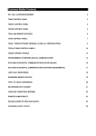
1
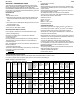
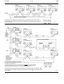
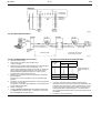
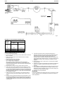
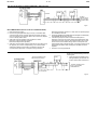
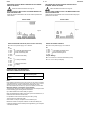
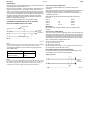
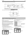
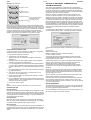
DS 2.501A
03/03
TM
COMMISSIONING DETAILS FOR SATCHNET NETWORKING SYSTEMS AND PRODUCTS
CONTENTS
Section
Page No.
1. WIRING PRACTICES ............................................................ 2
Introduction ................................................................................ 2
Definitions/Explanatory Notes .................................................... 2
Basic Rules ................................................................................ 2
Cable Specification .................................................................... 2
Cable Sizes & Length of Run ..................................................... 2
Installation Guidelines ................................................................ 3
Conductor Function.................................................................... 3
2. COMMUNICATION SCHEMES ............................................. 3
IAC400 ....................................................................................... 3
IAC Base Units on a LAN (No Touch-screens) .......................... 4
IAC Touch-screens and Base Units on a LAN ........................... 4
Remote Touch-screen Mounting Kit 565-2-601 ......................... 5
Remote Mounted Touch-screens using Kit 565-2-601
connected directly to MMC3701, IAC400 and 600s
(stand-alone mode) .................................................................... 5
Basic Diagram for MIU ............................................................... 6
MIU RS485 Repeater Mode....................................................... 6
MIU Commissioning, Repeater Mode ........................................ 6
MIU used on a WAN .................................................................. 7
MIU Switch Options when in Modem Mode ............................... 7
MIU Commissioning (Modem Interface Mode)........................... 7
MIU as an RS232 to RS485 Converter – Spec. No. 585-3-252. 8
MIU Commissioning, RS232 to RS485 Converter Mode ........... 8
Westermo MA-42 RS232 to RS485 Converter .......................... 8
Westermo Surface Mount Version MA–42 internal
Switch Settings........................................................................... 9
Westermo Non-Surface Mount Version MA–42 Internal
Switch Settings........................................................................... 9
Communication Configurations .................................................. 9
Available Communication Ports ................................................. 9
IRQ Settings............................................................................. 10
Hardwired Configuration for Opto 22 Cards............................. 10
RS485 Plug Wiring for Opto 22 Cards ..................................... 10
Opto 22 AC–24(AT) Card Set-up ............................................. 10
Opto 22 AC–32 Card Set-up .................................................... 10
PCM COM485 PCMCIA to RS485 Converter .......................... 10
Invensys is a trademark of Invensys plc and its subsidiaries and affiliates.
Section
Page No.
3. MODEM INITIALIZATION FOR SATCHNET
Pace, Linnet 12 & 24................................................................ 11
Pace, Linnet Quad Fx and Microlin Fx ..................................... 11
Pace, Microlin FX32 Plus ......................................................... 11
Hayes Smartmodem, Quad ..................................................... 11
Hayes Smartmodem, Optima 24.............................................. 11
Dowty, Quatro .......................................................................... 11
Multi Tech, MT 1432M ............................................................. 11
US Robotics Sportster 14,400/PC Fax .................................... 11
PSION, Bulldog........................................................................ 11
Pace, MOBI FAX 144............................................................... 11
Multitech, MT1932ZDXK.......................................................... 11
Megahertz USA Fax Modem.................................................... 11
Pace, Mobifax 24 ..................................................................... 11
US Robotics Sportster VI ......................................................... 11
RS Components 9000 Series .................................................. 11
Lasat Safire 144....................................................................... 11
Pace, Linnet 34 ........................................................................ 11
US Robotics Vi 14.4 28.8......................................................... 11
Supported Pagers .................................................................... 11
British Telecom Tap Protocol ................................................... 11
Remote Printer Modem Initialization ........................................ 11
4. POWER SUPPLY WIRING.................................................. 12
Multiple Controllers supplied from a Single Transformer ......... 12
Single Controller supplied from a Single Transformer ............. 12
5. SETTING THE BIT SWITCH ON IAC400/600 ONLY.......... 12
Custom Computer Configuration ............................................. 12
Setting the Controller Preset Application ................................. 12
Setting the Controller Address ................................................. 12
Cold Starting Controllers .......................................................... 13
Controller LED ......................................................................... 13
6. SATCHNET COMMUNICATION TROUBLE SHOOTING... 13
Group Addressing .................................................................... 13
Addressing Conventions .......................................................... 14
Bubbleland ............................................................................... 14
7. UPGRADING IAC FIRMWARE (EPROM)........................... 14
Static Precautions .................................................................... 14
With Version 1.XX.................................................................... 14
Configuration back-up.............................................................. 14
8. SATCHSOFT DATA FILES ................................................. 14
Introduction .............................................................................. 14
The SCN Directory ................................................................... 14
The LOG Directory ................................................................... 14
Images and Backgrounds ........................................................ 15
The Satchnet Root Directory.................................................... 15
The CNF Directory ................................................................... 15
Data Sheets
DS 2.501 - Specification Details
DS 2.501A
2 - 16
SECTION 1 – WIRING PRACTICES
This section sets out the standard specification for Satchnet Field
Wiring. The purpose of this specification is to install and commission
the products to ensure the compliance with EMC Directives
(89/336/EEC and 92/59/EEC). Adherence to this specification will also
prevent failure or mis-operation of the Satchnet networking system due
to the ingress of electrical noise.
INTRODUCTION
03/03
• Power supply connections
BASIC RULES
Satchnet Networking products input wiring must be carried out using
screened cable. (IAC600 up to 100m no screen required. 101 to 300m
screen required).
Satchnet Networking products serial link wiring must be carried out
using screened twisted pair cables.
Scope
All Satchnet field wiring cable conductors must be dedicated:
conductors may not be shared. (See "Definitions/Explanatory Notes").
This specification covers:-
See relevant Data Sheets for cable detail.
• Satchnet field wiring standards and practice, with reference to the
protection of the Satchnet Networking System against electrical
noise.
This specification does NOT cover:-
IAC600 - DS 2.951A
CSMC - DS 2.541A
MMC - DS 2.71A
MMC3601 - DS 2.751A
MMC3701 - DS 2.701A
IAC400 - DS 2.801A
• The protection of the cables against damage (mechanical, thermal,
chemical, radiation, etc)
• Insulation grades of cables
• Fire resistance, flammability of cables
• Smoke/Fume emission of cables
DEFINITIONS/EXPLANATORY NOTES
For the purpose of this document, the following definitions apply:-
Cables will incorporate a tinned copper conductor or conductors of
cross-sectional area 0.22mm, 0.52mm2 or 0.75mm2 PVC insulated.
Cables preferably will be multi-strand (e.g. 7/0.2, 16/0.2 or 24/0.2).
However, equivalent single conductor cables will be considered.
Cable cores are to be arranged in identifiable pairs. These pairs will
normally be screened individually.
• Extra-Low Voltage (ELV)
Normally not exceeding 50Vac or 120Vdc whether between
conductors or to Earth
Multicore cables are comprised of a number of pairs within a common
overall screen may be used provided that the installation guidelines for
Satchnet cables are followed (See "Installation").
• Low Voltage (LV)
Normally exceeding extra-low voltage but not exceeding 1000Vac or
1500Vdc between conductors or 600Vac or 900Vdc between any
conductor and Earth
The cable is to be sheathed overall in PVC.
The serial link (RS485/422) cable should be screened twisted
0.21mm2 or larger conductor, solid or stranded wire with a maximum
dc core resistance of 12 Ω per 100 metres and maximum capacitance
between the conductors of 60 pico Farads (pF) per metre.
Note: These definitions are taken from the BS7671 Requirements for
Electrical Installation.
• Input/Output signal terminals
Terminals on a Satchnet Networking controller which connect directly
to the internal circuitry of the controller
This EXCLUDES:-
CABLE SPECIFICATION
Non-Preferred cables
The following cable types are not recommended due to the physical
difficulty of glanding and termination:• Mineral Insulated Cables (MICC)
Part No.0/876-4-600-0-3
CABLE SIZES AND LENGTH OF RUN
The table below gives details of maximum cable lengths and recommended sizes for various functions.
For cable runs greater than those listed, please refer to Invensys Climate Controls Europe.
NOTE: Also refer to relevant Data Sheet.
TABLE 1 – MAXIMUM CABLE LENGTHS
Input
Cable AWG Diameter
Cross R/kM R/kM
Size
mm
Sectional
(Loop)
(Nominal) Area mm2 Ω
Ω
24
23
16/0.2
21
20
24/0.2
19
18
32/0.2
18
17
Input
DRT, DWT, RPP, RPW,
VFC
DOT, DST,
DRT
Override
DDT, DDU, (Adjustable) Timeswitch
DDH, DRH
RDE
Etc.
(0-10Vdc
Signal)
Max. Ω
per
conductor
7/0.2
Input
Output
XRM
Output
Output
Output
Output
a
ALX, ALXS, 0-10Vdc
24Vac
LAN
ARX,
Signal to
Supply to COMMS
Relays
ALE, ALES, ALE, ALES, Cable
ARE,
ARE,
ARES,
ARES,
AVUE
AVUE
15 Ω
10 Ω
5Ω
10 Ω
5Ω
50 Ω
3Ω
120 Ω
Max.
recom
-mended
metres
Max.
recom
-mended
metres
Max.
recom
-mended
metres
Absolute
Max.
metres
Max.
recom
-mended
metres
Max. recom
-mended
metres
Absolute
Max.
metres
Max.
recom
-mended
metres
Max.
Distance
300
b
30
Max.
Distance
1000
As Above
75
As Above
115
As Above
115
0.21
0.219
0.259
b
b
0.6
86
176
170
110
55
110
55
0.412
0.52
0.556
b
38
76
Max.
Distance
300
b
0.93
265
130
265
130
1.14
0.636
0.75
0.826
25.5
51
Max.
Distance
300
Max.
Distance
300
195
1.34
0.826
1.005
1.04
19.1
38.2
Max.
Distance
300
Max.
Distance
300
260
b
Max.
Distance
300
b
b
195
b
b
Max.
Distance
300
260
b
b
a Communication (LAN) cable:- <60pF per metre.
b 1.5mm2 core unscreened cable may be used for distances up to 100 metres. Also refer to Data Sheet for maximum impedances and lengths.
Max.
Distance
1000
Max.
Distance
1000
Max.
Distance
1000
03/03
3 - 16
DS 2.501A
INSTALLATION GUIDELINES
CONDUCTOR FUNCTION
Termination of Satchnet field wiring should be made at a dedicated
location or terminal rail, segregated from other terminals.
Conductor functions may not be shared. Each input pair shall have a
dedicated 0V conductor as part of the pair.
e.g. within a motor starter panel, a separate terminal rail (or section of
rail) should be employed.
Two or more Input/Output signals may NOT share a common 0V
conductor.
Where a common terminal rail is employed, a separation of 100mm
between Satchnet field wiring terminals and other terminals, must be
maintained. Satchnet field wiring from the terminal rail to the
networking controllers should be segregated from Mains and Power
wiring by running it in a separate trunking, tray or harness.
Under no circumstances shall Input signal cables share a common 0V
conductor with a power supply (e.g. to active sensors or actuators).
Where a field device such as a sensor or actuator employs a common
0V termination for both power and signal, then two 0V conductors must
be taken to the device: one for signal, one for power.
Screening of multicore cables, or individual pairs must be continuous.
SECTION 2 – COMMUNICATION SCHEMES
The screen of the cable must only be earthed at the common earth
point.
All IAC RS485 communication ports are optically isolated, which
protects the units from differential ground potentials e.g. earth loop
damage.
The common earth point should be connected to the controller earth
(0V Terminal) by a single cable which should be as short as possible
and no more than 150mm long.
The serial link cable must be screened and earthed at a common earth
point, located near to the personal Computer, not at the controller
devices. IAC200/400/600, Touch-screen and CVR serial link screens
must be connected to the IAC/Touch-screen/
CVR isolated earth terminal.
The RS485 mechanism works through a differential voltage which
must be referenced to a level, which is provided by the communication
cable screen making a 3 wire system.
To make communication as reliable as possible, the screen must be
connected to isolated ground as follows:
IAC 400
Non preferred cables (e.g. MICC)
Where these types of cables are mandatory, it is recommended that
they be terminated within a purpose-made terminal box immediately
adjacent to the network products cable entry point, and that final
connections to the network products be made using flexible, screened
cables as described above.
Since the copper sheath of the Mineral insulated cable forms the
earthed screen of these cables, only Satchnet controller Input
conductors at extra low voltage may be contained within the cable
sheath.
Fig.1
DS 2.501A
4 - 16
03/03
IAC BASE UNITS ON A LAN (NO TOUCH-SCREENS)
LAN from
PC or MIU
Upto 31 Networking Controllers and 1000m, more (upto 31 controllers and 1000m
if an MIU is used as a Repeater)
LAN B should be screened with the screen earthed only on a verified earth at the computer or MIU.
† LAN A and B screens should be connected to the isolated Ground Terminals
the LAN - see Fig.3A.
of each of the IACs on
Fig.2
IAC TOUCH SCREENS AND BASE UNITS ON A LAN
Touch
screen
addresses
65 to 95.
Up to 31
Touch
screens
DETAIL OF LAN SCREENING
ISOLATED
GROUND
ISOLATED
GROUND
More IACs
Fig.3A
To further
Networking
controllers
(Address range 1 to
63, MIU required if
total number is
greater than 31)
Upto 31*, MMC3701, IAC400/600s and 1000m
*The number of IAC controllers on a Touch-screen
Sub LAN is limited to 32 base units including the one
the Touch-screen is plugged into. Each Touch-screen
can display upto 256 parameters.
Controllers (including MIUs) on the main LAN and sub-LAN must not have conflicting addresses.
Controllers on different sub-LANs may use the same address. Ideally the sub-LAN addresses
should be kept within a range so as not to use up all of the main LAN addresses.
LAN B should be screened with the screen earthed only on a verified good earth at the computer or MIU.
† LAN A and B screens should be connected to the isolated Ground Terminals
LAN - see Fig.8.
of each of the IACs on the
Fig.3
03/03
5 - 16
DS 2.501A
REMOTE TOUCH-SCREEN MOUNTING KIT 565-2-601
ISOLATED
GROUND
ISOLATED
GROUND
1000 metres
MAX
Up to 31 MMC3701, IAC400/600s and 1000m
Fig.4
REMOTE MOUNTED TOUCH-SCREEN USING KIT 565-2-601 CONNECTED DIRECTLY TO MMC3701, IAC400 AND 600S (STAND ALONE
MODE)
Remote Touch-screen
Adaptor Kit 565-2-601
TOUCH-SCREEN
Supply
Note:- Maximum cable length
from the computer/MIU to the
Touch-screen is 1000m.
To MMC3701,
IAC400 and 600
To computer or MIU
MAIN LAN
SUB-LAN
Fig.5
DS 2.501A
6 - 16
03/03
BASIC DIAGRAM FOR MIU 3252
RS232 25
Way D Type
Connector
RS485
Serial Link
LAN
RS485
Serial Link
PC LAN
Fig.6
MIU 3252 RS485 REPEATER MODE
To further
controllers on
the LAN e.g.
MMC, CSMC,
IAC 600/400
Computer
RS485/422
Converter
Mode
Maximum 1000m
The MIU may be used on a
main LAN or a sub-LAN.
Fig.7
MIU 3252 COMMISSIONING (Repeater Mode)
1. Disconnect power supply.
2. Select mode of operation using bit switch eight.
i. OFF for repeater.
3. Select the communication speed for both the PC LAN and LAN by
using the jumpers (LK 6 and LK 5 respectively). The
communication speeds are marked on the PCB. It is possible to
set the LAN communication speed from a computer running
Satchnet Networking Software version 6.3 or later, if this is
required jumper LK 5 should be removed.
4. Set bit switch 7 to ON if the MIU is to operate as a transparent
(Dumb) repeater.
Set bit switch 7 to OFF if the MIU is to act as an addressable
repeater.
5. If bit switch 7 is set to ON then bit switches 1 to 6 are ignored and
can be left in any position.
If bit switch 7 is set to OFF then bit switches 1 to 6 are used to set
the MIU address (see table).
6. Switch on the power.
7. The RUN, MODEM and DUMB LEDs should light simultaneously.
The MODEM LED will then go OFF. If bit switch 7 is set to ON
then the DUMB LED will also stay ON.
MIU SWITCH OPTIONS WHEN IN REPEATER MODE
POSITION
SWITCH
(Increment
No.)
On
(open)
Off
1
2
3
4
5
6
1
2
4
8
16
32
0
0
0
0
0
0
7
Dumb
Repeater
Addressable
Repeater
8
-
Set to OFF
Address Setting only
used if bit switch 7 is
OFF
8. If the start up sequence does not follow the description in
instruction 7 then turn the power off and check that the MIU and
controllers have been correctly wired and that there are no short
circuits in the communication wiring. Switch on the power and
check the MIU start up sequence again. If no obvious fault is
found and the MIU still fails to start correctly then the MIU should
be replaced.
9. The MIU is now fully operational.
03/03
7 - 16
DS 2.501A
MIU 3252 USED ON A WAN
15m Max
EXTERNAL
MODEM
(DS 2.501)
Standard 25 Way
RS232 Cable
PUBLIC
SWITCHED
TELEPHONE
NETWORK
(PSTN)
MODEM
(DS 2.501)
SATCHNET TERMINAL
(DS 2.501)
Standard 25 Way
RS232 Cable
To other Networking
controllers e.g. MMC,
CSMC, IAC600, 400
Fig.8
MIU SWITCH OPTIONS WHEN IN MODEM MODE
SW1
SWITCH
(Increment
No.)
On
(open)
POSITION
Off
1
2
3
4
5
6
Not Hayes Modem
Reset
Hayes Modem
No Reset
7
-
Set to OFF
8
Set to ON
-
MIU3252 COMMISSIONING (Modem Interface Mode)
1. Disconnect the power supply.
2. Remove gland plate and using a 25 way ribbon cable connect the
MIU to a modem.
3. Select mode of operation from bit switches seven and eight.
Bit switch 7 OFF.
Bit switch 8 ON (modem operation).
4. Select modem type using bit switch 1.
ON - Disable modem initialisation.
OFF - Enable modem initialisation, Hayes command set
initialisation string sent to the modem is "ATV0E1M0S0=1Q0".
If ON is selected the modem must be manually configured before
connection to the MIU.
5. Bit switches 2 to 5 can be in any position and are ignored.
6. Select the communication speed for both the modem (PC LAN)
and LAN by using the jumpers (LK 6 and LK 5 respectively). The
communication speeds are marked on the PCB. It is possible to set
the LAN communication speed from a computer running Satchnet
Networking Software version 6.3 or later, if this is required jumper
LK 5 should be removed.
7. Switch bit switch 6 to the ON position. This will ensure that all
variables in memory are reset to default values. Switch on the
power.
8. The MIU checks the bit switch settings and if the modem is to be
initialised the MODEM LED on the MIU will flash at five times per
second whilst the modem is being initialised. Once initialisation is
complete the MODEM LED will stay ON and the RUN LED will be
constantly ON.
9. If the start up sequence does not follow the description in
instruction 8 then turn the power off and check that the MIU and
controllers have been correctly wired, that there are no short
circuits in the communication wiring and that the 25 way
connection lead is correctly connected. Switch on the power and
check the MIU start up sequence again. If no obvious fault is found
and the MIU still fails to start correctly then the MIU should be
replaced.
10. Set bit switch 6 to OFF so that if there is a power failure the MIU
will not be reset.
11. The MIU is now ready to accept data via the modem. By default the
address of the MIU in modem mode will be 0, this cannot be
changed.
12. At this stage the autodial telephone numbers, site mnemonic and
new poll data may be programmed into the MIU memory. This is
achieved by calling up the MIU using the auto answer facility from
the Satchnet PC and selecting the MIU.
13. The MIU is now fully operational.
MIU/MODEM
If bad communications are experienced it may be necessary to utilise
‘low loss’ telephone lines as supplied by the telephone company on
certain applications.
DS 2.501A
8 - 16
03/03
MIU 3252 AS AN RS232 TO RS485 CONVERTER - SPEC 585-3-252
LAN Port
Standard
Null
Modem
Cable
RS232
Port
inside
MIU
To further
controllers on the
LAN e.g. IAC400
600, CSMC, MMC
etc.
Fig.9
MIU COMMISSIONING (RS 232 TO RS 485 CONVERTER MODE)
1. Disconnect power supply.
2. Remove the gland plate and using a 25 way null modem cable
connect the MIU to the computer. Note the computer connector
may be a 9 way D type connector, either use a 9 to 25 way adapter
or a 9 to 25 way ribbon cable.
3. Select the mode of operation from bit switches 7 and 8.
Bit switch 7 ON (transparent operation).
Bit switch 8 ON (RS 232 operation).
4. Select the communication speed for both the PC and LAN by using
the jumpers (LK 6 and LK 5 respectively). The communication
speeds are marked on the PCB. It is possible to set the LAN
communication speed from a computer running Satchnet
Networking Software version 6.3 or later, if this is required jumper
LK 5 should be removed.
5. The RUN, MODEM and DUMB LED's should light simultaneously.
The MODEM LED will then go OFF.
6. If the start up sequence does not follow the description in
instruction 5 then turn the power off and check that the MIU and
controllers have been correctly wired and that there are no short
circuits in the communication wiring. Switch on the power and
check the MIU start up sequence again. If no obvious fault is found
and the MIU still fails to start correctly then the MIU should be
replaced.
7. The MIU is now fully operational.
WESTERMO MA-42 RS232 TO RS485 CONVERTER
Westermo Hardware Settings. See the
following text.
* Do not use Westermo User
Manual terminal numbers.
1. There are two types of MA-42 only
distinguishable by the fact that one
version uses surface mounted ICs.
To further controllers on the
LAN e.g. IAC400/600,
CSMC, MMC etc.
V24/RS232-C
Connection
Line Connection
Fig.10
03/03
9 - 16
WESTERMO SURFACE MOUNT VERSION MA-42 INTERNAL
SWITCH SETTINGS
DS 2.501A
WESTERMO NON SURFACE MOUNT VERSION MA-42
INTERNAL SWITCH SETTINGS
Follow the Static Precautions on Page 14.
Follow the Static Precautions on Page 14.
DO NOT OPEN THE MA–42 UNTIL THE MAINS WIRING HAS
BEEN DISCONNECTED.
DO NOT OPEN THE MA–42 UNTIL THE MAINS WIRING HAS
BEEN DISCONNECTED.
Open the MA-42 as described in its manual. Switch positions are
shown below.
Open the MA-42 as described in its manual. Switch and jumper
positions are as shown.
FRONT PANEL
FRONT PANEL
Fig.11
Fig.10
CONNECTORS ON REAR PANEL
CONNECTORS ON REAR PANEL
SWITCH SETTINGS FOR MA-42 (Article Number 3042-3003)
SWITCH SETTINGS FOR MA-42
S1 - set to local power supply 115 or 230Vac
S4 - set to local power supply 110 or 220Vac
S2
S5
1 - ON
2 - OFF
3 - OFF
4 - ON
5 - OFF
6 - OFF –
Transmitter activated by RTS
CTS controlled by RTS
DCD controlled by RTS
0ms RTS-CTS delay
S3
1 - ON
2 - OFF
3 - ON
4 - ON
5 - OFF
6 - OFF
1 - ON
2 - OFF
3 - OFF
4 - ON
5 - OFF
Transmitter activated by RTS
CTS controlled by RTS
DCD controlled by RTS
Jumper Settings
X6 - 7 to 8 and 2 to 1 Receiver terminated (4-wire)
4 Wire (Full duplex)
Receiver terminated
(4-wire)
COMMUNICATION CONFIGURATIONS
AVAILABLE COMMUNICATIONS PORTS
Computer Type
Maximum number of
communication ports
AT compatible PC 386/486/
Pentium
3 Ports if a bus mouse is used
Note:
Each available communication port on the computer can be used for a hardwired
output (RS422/485) or a modem output (RS232). One modem on the computer
will allow access to any number of remote sites. Hardwired sites using
stand-alone RS232/485 converters may require extra RS232 ports to be fitted.
Maximum number of controllers on the Network:
The maximum size of the system is determined by the computer used
but the following gives some general information:
Up to 999 hardwired or modem sites per system.
Each site (hardwired or modem) may have up to 32 controllers on it, to
extend this to 63 an MIU must be used.
It is possible to use more than 63 IACs per LAN by using
Touch-screens to create sub-LANs.
One modem or LAN per computer communications port.
Maximum number of computer modems or LANs is limited by the
number of slots and communication ports supported by your computer
- see table for details.
X7 - 2 to 1 Four wire (Full duplex)
DS 2.501A
10 - 16
03/03
IRQ SETTINGS
No two ports on an AT compatible machine may use the same interrupt
level (designated as IRQ numbers 0 to 7).
Serial ports set up as COM: 1 normally use IRQ: 4 and those set up as
COM: 2 normally use IRQ: 3. If no COM:2 is fitted, then COM: 3 or
COM: 4 may use IRQ: 3, otherwise either IRQ: 5 or IRQ: 7 should be
used. You may find interference with other adaptors/devices fitted to
your machine so a few attempts may be needed. Test the settings with
the SETUP software and observe the IRQ numbers given during
automatic configuration. See the Satchnet Reference Manual for
details of using the Setup program.
If an RS232 card is installed it is normally preset to COM 1.
OPTO-22 AC-24(AT) CARD SETUP
This card is for use with IBM PC-AT compatible and PS/2-30
computers.
Before use the computer may need to be configured from a Reference
disk supplied with your computer. This allows the computer to
recognise and operate the card. For details refer to the instructions
supplied with the card.
Make links B5, B6, B7 and those listed below with all other links
removed.
COM 1:
COM 2:
COM 3:
COM 4:
HARDWIRED CONFIGURATION FOR OPTO 22 CARDS
RS485 PLUG WIRING FOR OPTO 22 CARDS
A8,
A4,
A4, A8
COM 1
COM 2
COM 2
COM 2
IMPORTANT
Loopback Wire
See section called "IRQ SETTINGS" Page 10 for details of IRQ
numbers.
Hardwire
Link to
Controllers
Plug
Loopback Wire
Fig.12
Note:
Pin numbers refer only to the Opto 22 AC24 and AC34 cards. For other adaptors
refer to the Pin designations (Tx+ etc) and the manufacturers manual.
The table below details the communications card required for the
various IBM models:
OPTO-22 AC-32 CARD SETUP
This card is used in machines that support micro channel architecture
cards such as the IBM PS/2-50, 60, 70, 80 and 90 and can provide two
independent communication channels. Before use the computer must
be configured from the Reference disk supplied with your computer.
This allows the computer to recognise and operate the card. For details
refer to the instructions supplied with the card.
Jumpers should be set as follows:
A5, A6 & A7 for channel A
B5, B6 & B7 for channel B
Use the outputs from connector 1 J1 for channel A and connector J2
for channel B and remove all other jumpers.
PCM COM485 PCMCIA TO RS 485 CONVERTER
Computer
Opto-22 card
Set up the PCMCIA card using the software supplied with the card.
PC-AT, PS/2-30 (286)
AC24AT
The loopback is pre-wired for the PCM COM485
PS/2-50 and higher
AC32
Note: :
If you have a PS/2, any card installed in your computer will come with a disk of
files. The files on the disk allow the computer to recognise the new card. These
files should be copied onto your backup reference disk and your computer
re-configured in accordance with the card manufacturers instructions.
9 Way Connector
Hardwire
Link to
Controllers
Fig.13
03/03
11 - 16
DS 2.501A
SECTION 3 – MODEM INITIALIZATION FOR SATCHNET
The modems listed here are only for use with Satchnet Software.
MULTI TECH, MT1932ZDXK
For details of Modems supported for other Invensys products please
contact your local Invensys agent.
Compatible with:-
Satchnet 6.21 onwards and MIU
Command string:
AT &F
AT &E0 &E3 &E14 #F0$MB1200
&Q1$SB1200X4
AT &W
The modem(s) must be initialized with the correct command string.
The initialization (command) string can be set from the
communications icon of Satchnet Pro or the modem(s) can be
configured from a separate communications package.
If the modem is only to be used with Satchnet, then the AT&W
command can be used to fix the configuration in the modems non
volalite memory. The AT&F command is used to reset the modem to
its factory default settings.
The AT&F and AT&W should not be included in the Satchnet
initialization string.
AT&F and AT&W should be sent to the modem when it is first installed
to ensure the factory defaults are set in the modem.
PACE, LINNET 12 & 24
MEGAHERTZ USA FAX MODEM
Compatible with:-
Satchnet Plus onwards
Command string:-
AT &K0 F4
PACE, MOBIFAX 24
Compatible with:-
Satchnet Plus (6.20) onwards
MIU
Command string:-
None required.
Factory default
US ROBOTICS SPORTSTER VI
Compatible with:-
Compatible with:-
Satchnet 6.1 onwards
MIU
Satchnet Plus onwards
MIU
Command string:-
AT &A0 &K0 &M0 &N2 &H0 &R1 &S1
Command string:
None required. Factory default.
RS COMPONENTS 9000 SERIES
Notes: Beware of exchanges that have internal ring tones in excess of
1second, the Linnet 24 will not always answer.
PACE, LINNET QUAD FX AND MICROLIN FX
Version 2.02 or later.
Contact Pace if you have an earlier version.
Compatible with:-
Satchnet 6.1 onwards
MIU
Command string:
AT &S1 &K0 \N0 %C0
When a FAX is used &K6 may be written to the Modem. AT &K0 will
have to be written back to the Modem for use with Satchnet.
PACE, MICROLIN FX32 PLUS
Compatible with:-
Satchnet 6.11 onwards
Command string:-
None required. Factory default.
HAYES SMARTMODEM, QUAD
Compatible with:-
Satchnet 6.1 onwards
MIU
Command string:-
AT &C1 &D2
Compatible with:-
Satchnet Plus (6.20) onwards
Command string:-
AT &C1 &D2 &G2 &Q6 &S1
LASAT SAFIRE 144
Compatible with:-
Satchnet Plus (6.20) onwards
Command string:-
AT &F
AT &K0 %C0 F4 \N1
AT &W
PACE, LINNET 34
Compatible with:-
Satchnet Plus (6.20) onwards
Command string:-
AT &C0 \N0 &K0
US ROBOTICS Vi 14.4 28.8
Compatible with:-
Satchnet Plus (6.20) onwards
Command string:-
AT &F
AT &A0 &K0 &M0 &N2 &H0 &R1 &S1
AT &W
SUPPORTED PAGERS
HAYES SMARTMODEM, OPTIMA 24
BRITISH TELECOM TAP PROTOCOL
Compatible with:-
Satchnet Plus (6.20) onwards
MIU
Command string:
AT &C1 &D2 &Q0
British Telecom Message Master pager
British Telecom tone Master pager
The BT pager computer telephone number is 0345 581 354
DOWTY, QUATTRO
The pager ID number is derived from the pager telephone number
(supplied with the pager). To derive the pager ID take the last 6 digits
from the pager telephone number and put a 0 at the front of the 6 digits.
Compatible with:-
Satchnet 6.1 onwards
MIU
Command string:
AT &C1 &D2 &K0 &S0
Example:
Compatible with:-
Satchnet 6.1 onwards
MIU
REMOTE PRINTER MODEM INITIALIZATION
Command string:
None required. Factory default.
Pager telephone number 0893 123456
Pager ID is 0123456
MULTI TECH, MT1432M
US ROBOTICS SPORTSTER 14,400/PC FAX
Internal fax/modem card.
Compatible with:-
Satchnet Plus (6.20) onwards
Command string:
&B1 &A0 &K0
Bit Switch Settings (Default)
1 – Up
2 – Up
3 – Down
4 – Up
5 – Down
6 – Up
7 – Up
8 – Down
PSION, BULLDOG
Compatible with:-
Satchnet 6.21 onwards
Command string:
AT %D1 B0 &G2 &P1 S6=5 S8=5 S7=59
S11=70 X4
AT 4&D2 &C1
PACE, MOBI FAX 144
Compatible with:-
Satchnet 6.21 onwards
Command string:
AT &K0
AT F4
The remote printer modem must be setup using a terminal programme
running on a PC. The following modem settings are required:1.
2.
3.
4.
Baud rate set to 1200.
DTR to control line connection i.e. when DTR inactive, line drops.
Autoanswer mode activated (AT S0 = 1).
Quiet mode (AT Q1).
DS 2.501A
12 - 16
03/03
SECTION 4 - POWER SUPPLY WIRING
MULTIPLE CONTROLLERS SUPPLIED FROM A SINGLE TRANSFORMER
Fig.14
Do not loop the last controller wiring back to the transformer. Ensure the specified supply voltages can be
achieved at both ends of the supply wiring. DO NOT EARTH THE SUPPLY 0V LOCALLY.
SINGLE CONTROLLER SUPPLIED FROM A SINGLE TRANSFORMER
Fig.15
Ensure there are no earth loops in the supply wiring.
SECTION 5 – SETTING THE BIT SWITCH ON IAC400/600 ONLY
The bit switch is used for setting both the unit's address and it's preset
application. Which function is currently being performed is defined by
bit switch 7.
Bit switch 7 OFF - Preset set on bits 1-6
Bit switch 7 ON - Address set on bits 1-6
If you are to download your application from a computer using Satchnet
then you must select preset 0 from the bit switch. This will ensure that
in the event of a power failure, the software preset will not be
overwritten on subsequent power-up.
Example:- Loading Preset 3.
To enter either the address or preset into the controller toggle bit switch
8 from OFF to ON to OFF again. This causes the controller to reset
itself and it is only during such initialization that the preset/address is
read from the bit switch. They may be changed via satchsoft at
anytime.
Preset 3, switches 1 and 2 ON
all other switches OFF
Set switch 8 to ON
When the controller is to use one of the predefined presets, always
leave it with the relevant preset selected on the bit switch. This ensures
that in the event of memory corruption the controller can reload the
defaults applicable to the appropriate preset.
This procedure will enter
the preset application into
the controller memory.
Set switch 8 to OFF
CUSTOM COMPUTER CONFIGURATION
1. IACs should be set to preset 0.
SETTING THE CONTROLLER PRESET APPLICATION
1. Ensure bit switches 7 and 8 are both OFF.
2. Set the preset application number you require using bit switches 1
to 6.
Note: Preset 0 is set by setting bit switches 1 to 6 OFF.
3. Set bit switch 8 to ON.
4. Set bit switch 8 to OFF. This will enter the preset application
number into the controller.
SWITCH
No.
1
2
3
4
5
6
POSITION
ON
(open)
Off
1
2
4
8
16
32
0
0
0
0
0
0
Application
Preset Number
SETTING THE CONTROLLER ADDRESS
1.
2.
3.
4.
Ensure switch 7 is ON and switch 8 is OFF.
Set the address for the controller using bit switches 1 to 6.
Set bit switch 8 to ON.
Set bit switch 8 to OFF.
SWITCH
No.
1
2
3
4
5
6
POSITION
On
(open)
Off
1
2
4
8
16
32
0
0
0
0
0
0
Controller
Address
03/03
13 - 16
DS 2.501A
SECTION 6 –SATCHNET COMMUNICATION
TROUBLE SHOOTING
Example:- Set address 5.
Set switch 7 to ON
This section gives guidelines for interpreting the communications
failure percentage displayed on Satchnet. It is not intended that this will
provide an answer to every problem but providing that the Satchnet
wiring recommendations are followed (Section 1) it should be possible
to diagnose most communication problems.
Set address 5, set
switches 1 and 3 ON.
Set switch 8 to ON
This procedure will enter
the address into the
controller memory.
Set switch 8 to OFF
When using a user defined preset (or customized preset) first make
sure that preset 0 is selected via the bit switch. The unit should then be
left with the address selected on the bit switches (bit switch 7 ON). This
ensure that should data corruption occur the controller will not attempt
to load any default values. As the application is user defined the
controller cannot know what would be suitable defaults. The preset
setting can be checked using Satchnet via the system module.
COLD STARTING CONTROLLERS
In order to cold start an IAC controller (i.e. clear out the configuration
data) the following procedure should be followed.
1. Disconnect all outputs from the plant.
2. Set bit switch 1 ON, all others OFF.
Toggle bit switch 8. This causes the controller to load preset
application 1.
3. Set all bit switches to OFF. Toggle bit switch 8. This causes the
controller to load preset 0 (no application).
4. If you are using preset 0 you should now set the controller address.
If you are using a hardware preset application set the application
number on bit switches 1 to 6 and ensure that bit switch 7 is set to
OFF.
5. Once the application number is set it must be entered into the IAC
by toggling bit switch 8.
6. If the IAC is not to be connected to a computer then it is not
necessary to set an address for it.
7. Set the controller address (if required) on bit switches 1 to 6 and
set bit switch 7 to ON.
8. Once the address has been set it must be entered in to the IAC by
toggling bit switch 8. The controller address is now loaded and the
IAC will communicate at 1200 bps.
9. Re-connect outputs to plant.
Note:
Whenever a firmware upgrade is performed the unit must be cold started.
CONTROLLER LED
Normal Operation
On both the IAC400 and IAC200 controllers the on board LED is under
software control and should, under normal operation, flash at a regular
interval. The rate of flash is directly proportional to the loading imposed
by the application the controller is running, i.e. the more modules you
use the slower the LED flashes.
Unit Initialization
Whenever the controller is powered up or reset the LED will initially
flash very quickly before adopting the standard flash rate. (Only applies
to VAV207, VAS207 and DDC 206 and later versions).
Data Corruption
If a controller appears to be continually performing unit initialization, it
is likely that data corruption has occurred. Toggle bit switch 8 to reload
defaults. Download the configuration from Satchnet if it is a software
preset.
Before any analysis of possible problems can be performed, it is
necessary to get all controllers on an "even playing field" from the
Satchnet point of view. Ideally a duplicate copy of Satchnet should be
installed in a separate directory. Controllers should then be created but
no parameters extracted from them. Ideally all controllers should be
placed on the same Satchnet screen but if this is not possible group
them according to location. If possible all controllers should be running
the same application or no application. By following this procedure you
ensure that the polling of the controllers is evenly spread and thereby
make the communication failures statistic comparable between
controllers.
To view the failure percentage of a controller you must click on the
controller with the RIGHT button. The following window is displayed.
The operation of the failure statistic is influenced by many things such
as:
Protocol used,
Satchnet polling used,
Relative controller transceiver transmitter strengths,
Location of failing controller.
The precise nature of the failure percentage and how one failing
controller affects another is therefore site specific. However, some
general trends have been noted.
A failure percentage of 0-10% does not generally have a detrimental
effect on system performance. Some messages may fail but are
automatically re-tried by Satchnet. Where MIUs and IAC
touch-screens are used, there may be a slight increase in failure
percentage of 2-3% due to the message buffering these products
introduce.
Where two controllers have been given the same address the failure
percentage of that address will typically range from 40-90%. Other
working controllers will be affected and their failure percentages will
typically range from 10-30%.
Where a controller or group of controllers have a 100% failure rate,
suspect either addressing, wiring or hardware faults.
In general when tracing communications problems always start with
the unit with the highest failure rate. Isolation of this unit may well
improve the failure rates of the other controllers. The LAN may be split
up to help locate the fault.
GROUP ADDRESSING
The IAC200/400/600 may belong to 10 groups. The IAC200/400/ 600
will accept a group message if the message group address matches
any one of programmed group addresses.
Do not mix different controller types on the same group address. This
will result in corruption of the slave controller.
DS 2.501A
14 - 16
03/03
ADDRESSING CONVENTIONS
Where IAC600 Touch-screens are used on a LAN the following
addressing convention should be adopted.
SECTION 8 – SATCHNET DATA FILES
MIUs used in ‘modem mode’ to be address 0.
Controllers on Slave LANs to be addressed 1-31.
Controllers on the Master LAN to be addressed 32-63.
IAC600 Touch-screens to be address 65-95.
This section provides information about the files which Satchnet
creates when in use and which may be needed to back up a system or
transfer a system from one machine to another.
BUBBLELAND
Saving Configurations
Before saving a controller configuration to disk it is recommended that
the data is first uploaded from the controller. Satchnet Pro will
automatically prompt for this. Failure to do this may result in
uninitialized data being saved as part of the configuration which will
cause IAC controllers to reset when this data is subsequently sent to
them.
Always wear your
wrist strap
SECTION 7 – UPGRADING IAC FIRMWARE
(EPROM)
STATIC PRECAUTIONS
The components within this product can be damaged by static
electricity. In view of this anti-static precautions should be taken when
changing jumper, firmware (EPROM) or handling the PCB.
When upgrading controller firmware from versions 1.XX to 2.XX the
following procedure should be followed if a software preset is used.
With version 1.XX.
1. Enter the configuration library, select load a configuration from disk
and note the file name of the application you wish to upgrade.
2. Enter Bubbleland and for each module used make a note if it's
instantiation number (top left of the parameter box) and the
value/state of all the associated parameters.
3. Exit from Satchnet. The file noted in step 1 has a name that
consists of the following fields:
PPPV$NNN where;
PPP = Product identifier (DDC, VAV or VAS etc)
V
= Version number (i.e. 1 for 113, 2 for 206, 207 etc)
NNN = Configuration number
Enter the SATCHNET/LOG directory and copy PPP1$NNN.* to
PPP2$NNN.*
4. Upgrade the Controller firmware.
5. Perform a cold start, setting the same address as used before.
6. Run Satchnet.
7. Enter Bubbleland and select the system module. Put the controller
into ‘NULL OUTPUT’ (‘GO SAFE’).
8. Exit Bubbleland, select ‘configuration library’ and load the
appropriate configuration from disk. When prompted with ‘Send
configuration to controller?’ select NO. This will set up the
bubbleland configuration screen but will not send any parameter
values.
9. Enter Bubbleland. Using the notes made in (2) re-enter the
modules parameter data.
10. Take the controller out of ‘NULL OUTPUT’ (‘GO SAFE’).
11. Select the configuration library option from the controller main
menu and perform a "get data from controller".
12. Save the new configuration to disk.
CONFIGURATION BACK-UP
Check the configuration is operating correctly by resetting controller.
All parameters are checked on power up. If the Null Outputs button on
the System Module is ON the controller contains corrupt data. The
controller will need to be cold started and the corrupt parameter must
be re-entered.
Always ‘get data’ from controller before saving configuration to disk.
Put parameter values under the modules in bubbleland so that in the
unlikely event of losing the data they may be reprogrammed easily.
INTRODUCTION
When graphics or controllers are created in Satchnet, information
about them is stored in disk files. These files are divided amongst
several directories but all of the files together specify the current state
of the system.
THE SCN DIRECTORY
The SCN directory holds several different files but these must be
considered as a set. NEVER mix files from different Satchnet systems
or the results will be highly unpredictable.
An example of the SCN directory would be:0.SCN
1.SCN
2.SCN
VALS.DAT
SCRN.DAT
PRDCTS.DAT
TYPS.DAT
LIMS.DAT
SITES.DAT
LABELS.DAT
the graphics of the root screen
the first subscreen
another subscreen
.
.
. Various system data files
.
.
.
The SCN directory holds all the information needed to build up the
presentation graphics of your system along with alarm limits and the
last-read values of all active symbols.
THE LOG DIRECTORY
The LOG directory is used to hold data which is associated with
specific controllers and may be used to configure them. There may be
a very large number of files in this directory, falling into three main
categories:Controller files
-
Store information specific to each
controller in the system, and referenced
by address
Log Files
-
Store logged data
Config library files
-
Hold controller data for the config library
Controller Files
For every controller on the system, there are one or two files held in the
LOG directory.
These files are named using the site number and controller address to
ensure that the filenames are unique.
In the following, SS is the site number, i.e. the item number in the site
list of the site which the controller is designated as being on. AA is the
controller address, specified on the controller bit switch or by other
means as appropriate.
Controller .Dat Files
SS_AA.DAT e.g. 1_21.DAT
There is one of these files for each controller on your system. They hold
a copy of all the data in the controller from when it was last accessed.
Controller Bubble Files
SS_AA.BUB e.g. 1_21.BUB
There is one of these files for each IAC type controller on your system.
They hold the graphic information to form "Bubbleland" and are vital if
the bubbleland of a controller is to be accessed. .BUB files are stored
in addition to .DAT files.
Touch-screen Files
HNDAA.DAT
SS_AA.TCH (Satchnet V6.2 and later)
There is one of these files for each touch-screen configured by the
system. This file holds all the menus and view parameters for the
touch-screen. This file is additional to the .DAT file.
Logged Data Files – Prior to Satchnet V6.2
These files store logged data, either from Satchnet based logging, or
from controller based logging such as that carried out by the CSMC.
e.g. GRA16.LOG
One of these files is present for each logging parameter on your
system and additional files if CSMC logging is used. The number is
referred to an item in the .SCN directory and so these files cannot be
accessed unless kept along with the .SCN directory they were created
with.
03/03
15 - 16
DS 2.501A
Logged Data Files – Satchnet V6.2 and later
Logs are stored in the following files:-
THE SATCHNET ROOT DIRECTORY
LG_MM_YY.DAT
LG_MM_YY.REC
Some significant files are present in the main Satchnet directory.
Where
MM = Current Month
YY = Current Year
These are:
ALMCNF.DAT
All logs are stored in the same file. Files from previous months may be
back up and/or deleted.
Holds the setup of the various alarm
types.
ALARMS.DAT
The alarm history list.
Configuration Library Files
PASSE.FIC
The current users and passwords.
The configuration library option causes files to be saved - or rather
copied within the LOG directory. The filenames used are - for
example:-
POLL.SCH
Polling time schedules.
LOGON.DAT
The user logon list.
PARAM.DAT
Various setup items including mouse
speed, COM ports, time-outs etc. This
file is created by SETUP.EXE.
DDC1$001.LIB
DDC1$001.BUB
The names of these files are constructed as followed:XXXX$NNN.LIB and XXXX$NNN.BUB
where
All other files in the Satchnet main directory are supplied.
The .CNF Directory
XXXX is the controller type I.D.
and
NNN is generated as a number from 001 to 999 but can be
any three characters.
The numbers are generated automatically whenever a library file is
saved. If you wish to copy a file to a new system - or `lock a file' within
a system, the files may be renamed such that the last three characters
are not numbers. When transferring a library file pair, it is always wise
to rename the last characters to ensure that the file will not overwrite
an existing configuration. The user-defined label, which can be viewed
from within Satchnet, is held inside the file.
Satchnet systems are supplied with a set of library files named:
XXXX$.PRN.LIB
which contain the controllers pre-sets (N being the pre-set number).
The file with the extension .LIB is identical in format to the .DAT file.
The file with the extension .BUB is identical to the normal
controller.BUB files and will only be present if the controller is an IAC
type.
Although the .LIB files may be copied from one system to another,
great care is needed to ensure that compatibility is maintained. In
Satchnet version 6.11, the file MUST be used with the same .CNF file
as was in use when it was created. This restriction does not continue
to .LIB files created with version Satchnet Plus (6.20) although files
created with version Satchnet Plus (6.20) cannot be read by version
6.11.
If there is any doubt as to the compatibility of .LIB files, the following
upgrade procedure should be used:
Use this procedure if a .LIB and .BUB of uncertain compatibility is
to be transferred to a new system.
1. If a controller is present on the system, already programmed from
the .LIB and .BUB files on the old system, skip straight to 3). This
is a much easier procedure and should be followed wherever
possible.
2. Using the old system, go into bubbleland and note down all
significant values of the parameters within the modules.
3. From configuration library, select ‘Load Configuration from Disk’.
4. Pick out the configuration you require and answer ‘No’ to ‘Transmit
data’.
5. If the controller is already programmed with the configuration (by
the old system), you may skip to section 7).
6. Go into bubbleland and then, in each module, program the correct
parameters - as noted in section 2).
7. Select ‘Get Controller Data’ and wait for all data to be read.
8. Save the new format files in the configuration library. Delete the old
files as soon as possible to remove possible confusion.
IMAGES AND BACKGROUNDS
Satchnet Pro is supplied with a set of bit-map graphics (.CUT format)
which may be used to build up the screens. Backgrounds are held in
the BACKGRD directory while smaller images are placed in the IMG
directory. In some systems, these will be extended and any extra files
must be kept as part of the system configuration. It is also possible for
a system to have additional images added to the SYM directory in
order to provide extra active symbols.
The .CNF directory will be almost empty in production software under
normal circumstances. The only file present will be a file called `0'
which is there simply to ensure that the directory is created. All .CNF
files used by the system are included in the file CNF.PAK which is
present in the main directory. If you have a system which has some
.CNF files in the .CNF directory, they should not be necessary with a
new system. Satchnet will always use a .CNF file from the .CNF
directory in preference to the CNF.PAK file.
DS 2.501A
16 - 16
TM
Climate Controls Europe
Farnham Road
Slough
Berkshire SL1 4UH
United Kingdom
Telephone +44 (0)1753 611000
Facsimile +44 (0)1753 611001
Web site
www.climate-uk.invensys.com
03/03
WARNING THESE DEVICES ARE AT MAINS AND/OR LOW VOLTAGE. DO NOT
EXCEED RATED VOLTAGE. LOCAL WIRING REGULATIONS AND
USUAL SAFETY PRECAUTIONS MUST BE OBSERVED.
Cautions
• Ensure good earthing.
• STATIC PRECAUTIONS: The components within these products can
be damaged by static electricity. In view of this anti-static
precautions should be taken when changing jumper, firmware
(EPROM) or handling the PCB.
• Do not apply any voltages until a qualified technician has checked
the system and the commissioning procedures have been
completed.If any equipment covers have to be removed during the
installation of this equipment, ensure that they are refitted after
installation to comply with UL and CE safety requirements.
• Observe wiring precautions.
• Do not exceed maximum ambient temperature.
• Interference with parts under sealed covers invalidates guarantee.
• Design and performance of Invensys equipment is subject to
improvement and therefore liable to alteration without notice.
• Information is given for guidance only and Invensys does not accept
responsibility for the selection or installation of its products unless
information has been given by the Company in writing relating to a
specific application.
• A periodic system and tuning check of the control system is
recommended. Please contact your local Invensys service office for
details
©1997-2003 Invensys plc. All Rights Reserved.