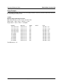
1
ADTRAN OPERATING SYSTEM (AOS)
Command Reference Guide
AOS Version 11.1
NetVanta 1000R Series Products
November 2005
61200510L1-35E
Command Reference Guide
Trademarks
Any brand names and product names included in this manual are trademarks, registered trademarks,
service marks, or trade names of their respective holders.
To the Holder of this Manual
The contents of this manual are current as of the date of publication. ADTRAN reserves the right to change
the contents without prior notice.
In no event will ADTRAN be liable for any special, incidental, or consequential damages or for
commercial losses even if ADTRAN has been advised thereof as a result of issue of this publication.
Software Licensing Agreement
Each ADTRAN product contains a single license for ADTRAN supplied software. Pursuant to the
Licensing Agreement, you may: (a) use the software on the purchased ADTRAN device only and (b) keep
a copy of the software for backup purposes. This Agreement covers all software installed on the system as
well as any software available on the ADTRAN website. In addition, certain ADTRAN systems may
contain additional conditions for obtaining software upgrades.
Conventions
Notes provide additional useful information.
Cautions signify information that could prevent service interruption or damage to the
equipment.
Warnings provide information that could prevent endangerment to human life.
901 Explorer Boulevard
P.O. Box 140000
Huntsville, AL 35814-4000
Phone: (256) 963-8000
www.adtran.com
Copyright © 2005 ADTRAN
All Rights Reserved.
Printed in the U.S.A.
61200510L1-35E
Copyright © 2005 ADTRAN
2
Command Reference Guide
Warranty and Customer Service
ADTRAN will repair and return this product within the warranty period if it does not meet its published
specifications or fails while in service. Warranty information can be found at www.adtran.com. (Click on
Warranty and Repair Information under Support.)
Product Registration
Registering your product helps ensure complete customer satisfaction. Please take time to register your
products on line at www.adtran.com. Click Service/Support and then on Product Registration under
Support.
Product Support Information
A return material authorization (RMA) is required prior to returning equipment to ADTRAN. For service,
RMA requests, training, or more information, use the contact information given below.
Repair and Return
If you determine that a repair is needed, please contact our Customer and Product Service (CaPS)
department to have an RMA number issued. CaPS should also be contacted to obtain information
regarding equipment currently in house or possible fees associated with repair.
CaPS Department
(256) 963-8722
Identify the RMA number clearly on the package (below the address), and return to the following address:
ADTRAN Customer and Product Service
901 Explorer Blvd. (East Tower)
Huntsville, Alabama 35806
RMA # _____________
61200510L1-35E
Copyright © 2005 ADTRAN
3
Command Reference Guide
Pre-Sales Inquiries and Applications Support
Your reseller should serve as the first point of contact for support. If additional pre-sales support is needed,
the ADTRAN Support website provides a variety of support services such as a searchable knowledge base,
latest product documentation, application briefs, case studies, and a link to submit a question to an
Applications Engineer. All of this, and more, is available at:
http://support.adtran.com
When needed, further pre-sales assistance is available by calling our Applications Engineering
Department.
Applications Engineering
(800) 615-1176
Post-Sales Support
Your reseller should serve as the first point of contact for support. If additional support is needed, the
ADTRAN Support website provides a variety of support services such as a searchable knowledge base,
updated firmware releases, latest product documentation, service request ticket generation and
trouble-shooting tools. All of this, and more, is available at:
http://support.adtran.com
When needed, further post-sales assistance is available by calling our Technical Support Center. Please
have your unit serial number available when you call.
Technical Support
(888) 4ADTRAN
International Technical Support 1-256-963-8716
Installation and Maintenance Support
The ADTRAN Custom Extended Services (ACES) program offers multiple types and levels of installation
and maintenance services which allow you to choose the kind of assistance you need. This support is
available at:
http://www.adtran.com/aces
For questions, call the ACES Help Desk.
ACES Help Desk
61200510L1-35E
Copyright © 2005 ADTRAN
(888) 874-ACES (2237)
4
Command Reference Guide
Training
The Enterprise Network (EN) Technical Training Department offers training on our most popular products.
These courses include overviews on product features and functions while covering applications of
ADTRAN's product lines. ADTRAN provides a variety of training options, including customized training
and courses taught at our facilities or at your site. For more information about training, please contact your
Territory Manager or the Enterprise Training Coordinator.
Training Phone
(800) 615-1176, ext. 7500
Training Fax
(256) 963-6700
Training Email
[email protected]
Export Statement
An Export License is required if an ADTRAN product is sold to a Government Entity outside of the EU+8
(Austria, Australia, Belgium, Czech Republic, Denmark, Finland, France, Germany, Greece, Hungary,
Ireland, Italy, Japan, Luxembourg, Netherlands, New Zealand, Norway, Poland, Portugal, Spain, Sweden,
Switzerland and the United Kingdom). This requirement is per DOC/BIS ruling G030477 issued 6/6/03.
This product also requires that the Exporter of Record file a semi-annual report with the BXA detailing the
information per EAR 740.17(5)(e)(2).
DOC - Department of Commerce
BIS - Bureau of Industry and Security
BXA - Bureau of Export Administration
61200510L1-35E
Copyright © 2005 ADTRAN
5
Command Reference Guide
Table of Contents
Table of Contents
Basic Mode Command Set . . . . . . . . . . . . . . . . . . . . . . . . . . . . . . . . . . . . . . . . . . . . . . . . . . . . . . 16
Common Commands . . . . . . . . . . . . . . . . . . . . . . . . . . . . . . . . . . . . . . . . . . . . . . . . . . . . . . . . . . . 26
Enable Mode Command Set . . . . . . . . . . . . . . . . . . . . . . . . . . . . . . . . . . . . . . . . . . . . . . . . . . . . . 36
Global Configuration Mode Command Set. . . . . . . . . . . . . . . . . . . . . . . . . . . . . . . . . . . . . . . . . 324
Line (Console) Interface Config Command Set . . . . . . . . . . . . . . . . . . . . . . . . . . . . . . . . . . . . . 532
Line (SSH) Interface Config Command Set . . . . . . . . . . . . . . . . . . . . . . . . . . . . . . . . . . . . . . . . 545
Line (Telnet) Interface Config Command Set. . . . . . . . . . . . . . . . . . . . . . . . . . . . . . . . . . . . . . . 553
ADSL Interface Config Command Set . . . . . . . . . . . . . . . . . . . . . . . . . . . . . . . . . . . . . . . . . . . . 562
BRI Interface Configuration Command set. . . . . . . . . . . . . . . . . . . . . . . . . . . . . . . . . . . . . . . . . 566
DDS Interface Configuration Command Set. . . . . . . . . . . . . . . . . . . . . . . . . . . . . . . . . . . . . . . . 578
DSX-1 Interface Configuration Command Set . . . . . . . . . . . . . . . . . . . . . . . . . . . . . . . . . . . . . . 586
E1 Interface Configuration Command Set . . . . . . . . . . . . . . . . . . . . . . . . . . . . . . . . . . . . . . . . . 596
Ethernet Interface Configuration Command Set . . . . . . . . . . . . . . . . . . . . . . . . . . . . . . . . . . . . . 613
G.703 Interface Configuration Command set . . . . . . . . . . . . . . . . . . . . . . . . . . . . . . . . . . . . . . . 664
Modem Interface Configuration Command Set . . . . . . . . . . . . . . . . . . . . . . . . . . . . . . . . . . . . . 671
Serial Interface Configuration Command Set . . . . . . . . . . . . . . . . . . . . . . . . . . . . . . . . . . . . . . . 676
SHDSL Interface Configuration Command Set . . . . . . . . . . . . . . . . . . . . . . . . . . . . . . . . . . . . . 685
T1 Interface Configuration Command Set . . . . . . . . . . . . . . . . . . . . . . . . . . . . . . . . . . . . . . . . . 697
ATM Interface Config Command Set . . . . . . . . . . . . . . . . . . . . . . . . . . . . . . . . . . . . . . . . . . . . . 714
ATM Sub-Interface Config Command Set . . . . . . . . . . . . . . . . . . . . . . . . . . . . . . . . . . . . . . . . . 717
Demand Interface Configuration Command Set . . . . . . . . . . . . . . . . . . . . . . . . . . . . . . . . . . . . . 782
Frame Relay Interface Config Command Set . . . . . . . . . . . . . . . . . . . . . . . . . . . . . . . . . . . . . . . 843
Frame Relay Sub-Interface Config Command Set . . . . . . . . . . . . . . . . . . . . . . . . . . . . . . . . . . . 865
HDLC Command Set. . . . . . . . . . . . . . . . . . . . . . . . . . . . . . . . . . . . . . . . . . . . . . . . . . . . . . . . . . 926
Loopback Interface Configuration Command Set. . . . . . . . . . . . . . . . . . . . . . . . . . . . . . . . . . . . 983
Port Channel Interface Config Command Set . . . . . . . . . . . . . . . . . . . . . . . . . . . . . . . . . . . . . . 1013
PPP Interface Configuration Command Set . . . . . . . . . . . . . . . . . . . . . . . . . . . . . . . . . . . . . . . 1037
Tunnel Configuration Command Set. . . . . . . . . . . . . . . . . . . . . . . . . . . . . . . . . . . . . . . . . . . . . 1109
VLAN Configuration Command Set. . . . . . . . . . . . . . . . . . . . . . . . . . . . . . . . . . . . . . . . . . . . . 1163
VLAN Database Configuration Command Set . . . . . . . . . . . . . . . . . . . . . . . . . . . . . . . . . . . . . 1167
VLAN Interface Config Command Set . . . . . . . . . . . . . . . . . . . . . . . . . . . . . . . . . . . . . . . . . . . 1176
CA Profile Configuration Command Set. . . . . . . . . . . . . . . . . . . . . . . . . . . . . . . . . . . . . . . . . . 1215
Certificate Configuration Command Set . . . . . . . . . . . . . . . . . . . . . . . . . . . . . . . . . . . . . . . . . . 1226
Crypto Map IKE Command Set . . . . . . . . . . . . . . . . . . . . . . . . . . . . . . . . . . . . . . . . . . . . . . . . 1230
Crypto Map Manual Command Set. . . . . . . . . . . . . . . . . . . . . . . . . . . . . . . . . . . . . . . . . . . . . . 1239
IKE Client Command Set . . . . . . . . . . . . . . . . . . . . . . . . . . . . . . . . . . . . . . . . . . . . . . . . . . . . . 1250
IKE Policy Attributes Command Set. . . . . . . . . . . . . . . . . . . . . . . . . . . . . . . . . . . . . . . . . . . . . 1254
IKE Policy Command Set . . . . . . . . . . . . . . . . . . . . . . . . . . . . . . . . . . . . . . . . . . . . . . . . . . . . . 1260
AS Path List Command Set . . . . . . . . . . . . . . . . . . . . . . . . . . . . . . . . . . . . . . . . . . . . . . . . . . . . 1273
61200510L1-35E
Copyright © 2005 ADTRAN
6
Command Reference Guide
Table of Contents
BGP Configuration Command Set . . . . . . . . . . . . . . . . . . . . . . . . . . . . . . . . . . . . . . . . . . . . . .
BGP Neighbor Configuration Command Set . . . . . . . . . . . . . . . . . . . . . . . . . . . . . . . . . . . . . .
Community List Command Set . . . . . . . . . . . . . . . . . . . . . . . . . . . . . . . . . . . . . . . . . . . . . . . . .
Router (OSPF) Configuration Command Set . . . . . . . . . . . . . . . . . . . . . . . . . . . . . . . . . . . . . .
Router (RIP) Configuration Command Set . . . . . . . . . . . . . . . . . . . . . . . . . . . . . . . . . . . . . . . .
DHCP Pool Command Set . . . . . . . . . . . . . . . . . . . . . . . . . . . . . . . . . . . . . . . . . . . . . . . . . . . .
Quality of Service (QoS) Map Commands . . . . . . . . . . . . . . . . . . . . . . . . . . . . . . . . . . . . . . . .
Radius Group Command Set . . . . . . . . . . . . . . . . . . . . . . . . . . . . . . . . . . . . . . . . . . . . . . . . . . .
Route Map Command Set . . . . . . . . . . . . . . . . . . . . . . . . . . . . . . . . . . . . . . . . . . . . . . . . . . . . .
TACACS+ Group Configuration Command Set. . . . . . . . . . . . . . . . . . . . . . . . . . . . . . . . . . . .
Index . . . . . . . . . . . . . . . . . . . . . . . . . . . . . . . . . . . . . . . . . . . . . . . . . . . . . . . . . . . . . . . . . . . . . . . . . . . .
61200510L1-35E
Copyright © 2005 ADTRAN
1276
1282
1298
1301
1316
1327
1345
1351
1353
1363
1365
7
Command Reference Guide
CLI Introduction
REFERENCE GUIDE INTRODUCTION
This manual provides information about the commands that are available with all of the NetVanta Series
units.
This manual provides information about the commands that are available with NetVanta 1000R Series
units. For a list of all of the commands available through the CLI, see 61950860L1-35L (All Products).
If you are new to the ADTRAN Operating System’s (AOS) Command Line Interface (CLI), take a few
moments to review the information provided in the section which follows (CLI Introduction).
If you are already familiar with the CLI and you need information on a specific command or group of
commands, proceed to Command Descriptions on page 14 of this guide.
CLI INTRODUCTION
This portion of the Command Reference Guide is designed to introduce you to the basic concepts and
strategies associated with using the AOS CLI.
Accessing the CLI from your PC . . . . . . . . . . . . . . . . . . . . . . . . . . . . . . . . . . . . . . . . . . . . . . . . . . . . . . 8
Understanding Command Security Levels . . . . . . . . . . . . . . . . . . . . . . . . . . . . . . . . . . . . . . . . . . . . . . 9
Understanding Configuration Modes . . . . . . . . . . . . . . . . . . . . . . . . . . . . . . . . . . . . . . . . . . . . . . . . . . 9
Using CLI Shortcuts . . . . . . . . . . . . . . . . . . . . . . . . . . . . . . . . . . . . . . . . . . . . . . . . . . . . . . . . . . . . . . 10
Performing Common CLI Functions . . . . . . . . . . . . . . . . . . . . . . . . . . . . . . . . . . . . . . . . . . . . . . . . . . 12
Understanding CLI Error Messages . . . . . . . . . . . . . . . . . . . . . . . . . . . . . . . . . . . . . . . . . . . . . . . . . . 13
Accessing the CLI from your PC
All products using the AOS are initially accessed by connecting a VT100 terminal (or terminal emulator)
to the CONSOLE port located on the rear panel of the unit using a standard DB-9 (male) to DB-9 (female)
serial cable. Configure the VT100 terminal or terminal emulation software to the following settings:
•
•
•
•
•
9600 baud
8 data bits
No parity
1 stop bit
No flow control
For more details on connecting to your unit, refer to the Quick Configuration Guides and
Quick Start Guides located on the ADTRAN OS Documentation CD provided with your
unit.
61200510L1-35E
Copyright © 2005 ADTRAN
8
Command Reference Guide
Understanding Command Security Levels
Understanding Command Security Levels
The ADTRAN CLI has two command security levels — Basic and Enable. Both levels support a specific
set of commands. For example, all interface configuration commands are accessible only through the
Enable security level. The following table contains a brief description of each level.
Level
Access by...
Prompt
With this level you can...
Basic
beginning an AOS session.
>
•
•
•
entering enable while in the #
Basic command security level
as follows:
>enable
Enable
•
•
•
display system information
perform traceroute and ping
functions
open a Telnet session
manage the startup and running
configurations
use the debug commands
enter any of the configuration modes
To prevent unauthorized users from accessing the configuration functions of your AOS
product, immediately install an Enable-level password. Refer to the Quick Configuration
Guides and Quick Start Guides located on the ADTRAN OS Documentation CD provided
with your unit for more information on configuring a password.
Understanding Configuration Modes
The ADTRAN CLI has four configuration modes to organize the configuration commands – Global, Line,
Router, and Interface. Each configuration mode supports a set of commands specific to the configurable
parameters for the mode. For example, all Frame Relay configuration commands are accessible only
through the interface configuration mode (for the virtual Frame Relay interface). The following table
contains a brief description of each level.
Mode
Access by...
Sample Prompt
With this mode you
can...
Global
entering config while at the Enable
command security level prompt.
For example:
>enable
#config term
(config)#
•
•
•
•
61200510L1-35E
Copyright © 2005 ADTRAN
set the system’s
Enable-level
password(s)
configure the system
global IP parameters
configure the SNMP
parameters
enter any of the
other configuration
modes
9
Command Reference Guide
Using CLI Shortcuts
Mode
Access by...
Line
(config-con0)#
specifying a line (console or Telnet)
while at the Global Configuration mode
prompt.
For example:
>enable
#config term
(config)#line console 0
•
entering router rip or router ospf
(config-rip)#
while at the Global Configuration mode
prompt.
For example:
>enable
#config term
(config)#router rip
•
specifying an interface (T1, Ethernet,
Frame Relay, ppp, etc.) while in the
Global Configuration mode.
For example:
>enable
#config term
(config)#int eth 0/1
•
Router
Interface
Sample Prompt
(config-eth 0/1)#
(The above prompt is for the
Ethernet LAN interface located
on the rear panel of the unit.)
With this mode you
can...
•
•
•
configure the
console terminal
settings (datarate,
login password, etc.)
create Telnet logins
and specify their
parameters (login
password, etc.)
configure RIP or
OSPF parameters
suppress route
updates
redistribute
information from
outside routing
sources (protocols)
configure
parameters for the
available LAN and
WAN interfaces
Using CLI Shortcuts
The ADTRAN CLI provides several shortcuts which help you configure your AOS product more easily.
See the following table for descriptions.
Shortcut
Description
Up arrow key
To re-display a previously entered command, use the up arrow key. Continuing to press the
up arrow key cycles through all commands entered starting with the most recent
command.
<Tab> key
Pressing the <Tab> key after entering a partial (but unique) command will complete the
command, display it on the command prompt line, and wait for further input.
61200510L1-35E
Copyright © 2005 ADTRAN
10
Command Reference Guide
Using CLI Shortcuts
Shortcut
Description
?
The ADTRAN CLI contains help to guide you through the configuration process. Using the
question mark, do any of the following:
• Display a list of all subcommands in the current mode. For example:
(config-t1 1/1)#coding ?
ami - Alternate Mark Inversion
b8zs - Bipolar Eight Zero Substitution
•
Display a list of available commands beginning with certain letter(s). For example:
(config)#ip d?
default-gateway dhcp-server domain-lookup domain-name domain-proxy
•
Obtain syntax help for a specific command by entering the command, a space, and
then a question mark (?). The ADTRAN CLI displays the range of values and a brief
description of the next parameter expected for that particular command. For
example:
(config-eth 0/1)#mtu ?
<64-1500> - MTU (bytes)
<Ctrl + A>
Jump to the beginning of the displayed command line. This shortcut is helpful when using
the no form of commands (when available). For example, pressing <Ctrl + A> at the
following prompt will place the cursor directly after the #:
(config-eth 0/1)#ip address 192.33.55.6
<Ctrl + E>
Jump to the end of the displayed command line. For example, pressing <Ctrl + E> at the
following prompt will place the cursor directly after the 6:
(config-eth 0/1)#ip address 192.33.55.6
<Ctrl + U>
Clears the current displayed command line. The following provides an example of the
<Ctrl + U> feature:
(config-eth 0/1)#ip address 192.33.55.6 (Press <Ctrl + U> here)
(config-eth 0/1)#
auto finish
61200510L1-35E
You need only enter enough letters to identify a command as unique. For example,
entering int t1 1/1 at the Global configuration prompt provides you access to the
configuration parameters for the specified T1 interface. Entering interface t1 1/1 would
work as well, but is not necessary.
Copyright © 2005 ADTRAN
11
Command Reference Guide
Performing Common CLI Functions
Performing Common CLI Functions
The following table contains descriptions of common CLI commands.
Command
Description
do
The do command provides a way to execute commands in
other command sets without taking the time to exit the
current and enter the desired one. The following example
shows the do command used to view the Frame Relay
interface configuration while currently in the T1 interface
command set:
(config)#interface t1 1/1
(config-t1 1/1)#do show interfaces fr 7
no
To undo an issued command or to disable a feature, enter
no before the command.
For example:
no shutdown t1 1/1
copy running-config startup-config
When you are ready to save the changes made to the
configuration, enter this command. This copies your
changes to the unit’s nonvolatile random access memory
(NVRAM). Once the save is complete, the changes are
retained even if the unit is shut down or suffers a power
outage.
show running config
Displays the current configuration.
debug
Use the debug command to troubleshoot problems you
may be experiencing on your network. These commands
provide additional information to help you better interpret
possible problems. For information on specific debug
commands, refer to the section Enable Mode Command
Set on page 36.
undebug all
To turn off any active debug commands, enter this
command.
The overhead associated with the debug command takes up a large portion of your AOS
product’s resources and at times can halt other processes. It is best to only use the debug
command during times when the network resources are in low demand (non-peak hours,
weekends, etc.).
61200510L1-35E
Copyright © 2005 ADTRAN
12
Command Reference Guide
Understanding CLI Error Messages
Understanding CLI Error Messages
The following table lists and defines some of the more common error messages given in the CLI.
Message
Helpful Hints
%Ambiguous command
%Unrecognized Command
The command may not be valid in the current command mode, or you may
not have entered enough correct characters for the command to be
recognized. Try using the ? command to determine your error. See Using
CLI Shortcuts on page 10 for more information.
%Invalid or incomplete
command
The command may not be valid in the current command mode, or you may
not have entered all of the pertinent information required to make the
command valid. Try using the ? command to determine your error. See
Using CLI Shortcuts on page 10 for more information.
%Invalid input detected at
“^” marker
The error in command entry is located where the caret (^) mark appears.
Enter a question mark at the prompt. The system will display a list of
applicable commands or will give syntax information for the entry.
61200510L1-35E
Copyright © 2005 ADTRAN
13
Command Reference Guide
Command Descriptions
COMMAND DESCRIPTIONS
This portion of the guide provides a detailed listing of all available commands for the ADTRAN OS CLI
(organized by command set). Each command listing contains pertinent information including the default
value, a description of all sub-command parameters, functional notes for using the command, and a brief
technology review. To search for a particular command alphabetically, use the Index at the end of this
document. To search for information on a group of commands within a particular command set, use the
linked references given below:
Basic Mode Command Set on page 16
Common Commands on page 26
Enable Mode Command Set on page 36
Global Configuration Mode Command Set on page 324
Line Interface Command Sets
Line (Console) Interface Config Command Set on page 532
Line (SSH) Interface Config Command Set on page 545
Line (Telnet) Interface Config Command Set on page 553
Physical Interface Command Sets
ADSL Interface Config Command Set on page 562
BRI Interface Configuration Command set on page 566
DDS Interface Configuration Command Set on page 578
DSX-1 Interface Configuration Command Set on page 586
E1 Interface Configuration Command Set on page 596
Ethernet Interface Configuration Command Set on page 613
G.703 Interface Configuration Command set on page 664
Modem Interface Configuration Command Set on page 671
Serial Interface Configuration Command Set on page 676
SHDSL Interface Configuration Command Set on page 685
T1 Interface Configuration Command Set on page 697
Virtual Interface Command Sets
ATM Interface Config Command Set on page 714
ATM Sub-Interface Config Command Set on page 717
Demand Interface Configuration Command Set on page 782
Frame Relay Interface Config Command Set on page 843
Frame Relay Sub-Interface Config Command Set on page 865
HDLC Command Set on page 926
Loopback Interface Configuration Command Set on page 983
Port Channel Interface Config Command Set on page 1013
PPP Interface Configuration Command Set on page 1037
Tunnel Configuration Command Set on page 1109
VLAN Configuration Command Set on page 1163
VLAN Database Configuration Command Set on page 1167
VLAN Interface Config Command Set on page 1176
61200510L1-35E
Copyright © 2005 ADTRAN
14
Command Reference Guide
Command Descriptions
VPN Parameter Command Sets
CA Profile Configuration Command Set on page 1215
Certificate Configuration Command Set on page 1226
Crypto Map IKE Command Set on page 1230
Crypto Map Manual Command Set on page 1239
IKE Client Command Set on page 1250
IKE Policy Attributes Command Set on page 1254
IKE Policy Command Set on page 1260
Routing Protocol Command Sets
AS Path List Command Set on page 1273
BGP Configuration Command Set on page 1276
BGP Neighbor Configuration Command Set on page 1282
Community List Command Set on page 1298
Router (OSPF) Configuration Command Set on page 1301
Router (RIP) Configuration Command Set on page 1316
Security and Services Command Sets
DHCP Pool Command Set on page 1327
Quality of Service (QoS) Map Commands on page 1345
Radius Group Command Set on page 1351
Route Map Command Set on page 1353
TACACS+ Group Configuration Command Set on page 1363
61200510L1-35E
Copyright © 2005 ADTRAN
15
Command Reference Guide
Basic Mode Command Set
BASIC MODE COMMAND SET
To activate the Basic mode, simply log in to the unit. After connecting the unit to a VT100 terminal (or
terminal emulator) and activating a terminal session, the following prompt displays:
>
The following command is common to multiple command sets and is covered in a centralized section of
this guide. For more information, refer to the section listed below:
exit on page 34
All other commands for this command set are described in this section in alphabetical order.
enable on page 17
logout on page 18
ping <address> on page 19
show clock on page 21
show snmp on page 22
show version on page 23
telnet <address> on page 24
traceroute <address> on page 25
61200510L1-35E
Copyright © 2005 ADTRAN
16
Command Reference Guide
Basic Mode Command Set
enable
Use the enable command (at the Basic Command mode prompt) to enter the Enable Command mode. Use
the disable command to exit the Enable Command mode. Refer to Enable Mode Command Set on page 36
for more information.
Syntax Description
No subcommands.
Default Values
No default value necessary for this command.
Applicable Platforms
This command applies to the NetVanta 300, 1000, 1000R, 2000, 3000, 4000, and 5000 and
Total Access 900 Series units.
Command History
Release 1.1
Command was introduced.
Functional Notes
The Enable Command mode provides access to operating and configuration parameters and should be
password protected to prevent unauthorized use. Use the enable password command (found in the
Global Configuration mode) to specify an Enable Command mode password. If the password is set,
access to the Enable Commands (and all other “privileged” commands) is only granted when the correct
password is entered. Refer to enable password [md5] <password> on page 380 for more information.
Usage Examples
The following example enters the Enable Command mode and defines an Enable Command mode
password:
>enable
#configure terminal
(config)#enable password ADTRAN
At the next login, the following sequence must occur:
>enable
Password: ******
#
61200510L1-35E
Copyright © 2005 ADTRAN
17
Command Reference Guide
Basic Mode Command Set
logout
Use the logout command to terminate the current session and return to the login screen.
Syntax Description
No subcommands.
Default Values
No defaults necessary for this command.
Applicable Platforms
This command applies to the NetVanta 300, 1000, 1000R, 2000, 3000, 4000, and 5000 and
Total Access 900 Series units.
Command History
Release 1.1
Command was introduced.
Usage Examples
The following example shows the logout command being executed in the Basic mode:
>logout
Session now available
Press RETURN to get started.
61200510L1-35E
Copyright © 2005 ADTRAN
18
Command Reference Guide
Basic Mode Command Set
ping <address>
Use the ping command (at the Basic Command mode prompt) to verify Internet Protocol (IP) network
connectivity.
Syntax Description
<address>
Specifies the IP address of the system to ping. Entering the ping command with
no specified address prompts the user with parameters for a more detailed ping
configuration. Refer to Functional Notes (below) for more information.
Default Values
No default value necessary for this command.
Applicable Platforms
This command applies to the NetVanta 300, 1000, 1000R, 2000, 3000, 4000, and 5000 and
Total Access 900 Series units.
Command History
Release 1.1
Command was introduced.Command was introduced.
Functional Notes
The ping command helps diagnose basic IP network connectivity using the Packet InterNet Groper
program to repeatedly bounce Internet Control Message Protocol (ICMP) echo-request packets off a
system (using a specified IP address). The AOS allows executing a standard ping request to a specified IP
address or provides a set of prompts to configure a more specific ping configuration.
The following is a list of output messages from the ping command:
!
Success
Destination Host Unreachable
$
Invalid Host Address
X
TTL Expired in Transit
?
Unknown Host
*
Request Timed Out
61200510L1-35E
Copyright © 2005 ADTRAN
19
Command Reference Guide
Basic Mode Command Set
The following is a list of available extended ping fields with descriptions:
Target IP address
Repeat Count
Specifies the IP address of the system to ping.
Specifies the number of ping packets to send to the system
(valid range: 1 to 1,000,000).
Datagram Size
Specifies the size (in bytes) of the ping packet (valid range: 1 to 1448).
Timeout in Seconds
Specifies the timeout period after which a ping is considered unsuccessful
(valid range: 1 to 5 seconds).
Extended Commands
Specifies whether additional commands are desired for more ping
configuration parameters.
Source Address (or interface) Specifies the IP address to use as the source address in the ECHO_REQ
packets.
Data Pattern
Specifies an alphanumeric string to use (the ASCII equivalent) as the data
pattern in the ECHO_REQ packets.
Sweep Range of Sizes
Varies the sizes of the ECHO_REQ packets transmitted.
Sweep Min Size
Specifies the minimum size of the ECHO_REQ packet
(valid range: 0 to 1448).
Sweep Max Size
Specifies the maximum size of the ECHO_REQ packet
(valid range: Sweep Min Size to 1448).
Sweep Interval
Specifies the interval used to determine packet size when performing the
sweep (valid range: 1 to 1448).
Verbose Output
Specifies an extended results output.
Usage Examples
The following is an example of a successful ping command:
>ping
Target IP address:192.168.0.30
Repeat count[1-1000000]:5
Datagram Size [1-1000000]:100
Timeout in seconds [1-5]:2
Extended Commands? [y or n]:n
Type CTRL+C to abort.
Legend: '!' = Success '?' = Unknown host '$' = Invalid host address
'*' = Request timed out '-' = Destination host unreachable
'x' = TTL expired in transit
Pinging 192.168.0.30 with 100 bytes of data:
!!!!!
Success rate is 100 percent (5/5) round-trip min/avg/max = 19/20.8/25 ms
61200510L1-35E
Copyright © 2005 ADTRAN
20
Command Reference Guide
Basic Mode Command Set
show clock
Use the show clock command to display the system time and date entered using the clock set command.
Refer to the section clock set <time> <day> <month> <year> on page 82 for more information.
Syntax Description
No subcommands.
Default Values
No default value necessary for this command.
Applicable Platforms
This command applies to the NetVanta 300, 1000, 1000R, 2000, 3000, 4000, and 5000 and
Total Access 900 Series units.
Command History
Release 1.1
Command was introduced.
Usage Examples
The following example displays the current time and data from the system clock:
>show clock
23:35:07 UTC Tue Aug 20 2002
61200510L1-35E
Copyright © 2005 ADTRAN
21
Command Reference Guide
Basic Mode Command Set
show snmp
Use the show snmp command to display the system Simple Network Management Protocol (SNMP)
parameters and current status of SNMP communications.
Syntax Description
No subcommands.
Default Values
No default value necessary for this command.
Applicable Platforms
This command applies to the NetVanta 300, 1000, 1000R, 2000, 3000, 4000, and 5000 and
Total Access 900 Series units.
Command History
Release 1.1
Command was introduced.
Usage Examples
The following is an example output using the show snmp command for a system with SNMP disabled and
the default chassis and contact parameters:
>show snmp
Chassis: Chassis ID
Contact: Customer Service
0 Rx SNMP packets
0 Bad community names
0 Bad community uses
0 Bad versions
0 Silent drops
0 Proxy drops
0 ASN parse errors
61200510L1-35E
Copyright © 2005 ADTRAN
22
Command Reference Guide
Basic Mode Command Set
show version
Use the show version command to display the current AOS version information.
Syntax Description
No subcommands.
Default Values
No default value necessary for this command.
Applicable Platforms
This command applies to the NetVanta 300, 1000, 1000R, 2000, 3000, 4000, and 5000 and
Total Access 900 Series units.
Command History
Release 1.1
Command was introduced.
Usage Examples
The following is a sample show version output:
>show version
AOS version 06.01.00
Checksum: 1F0D5243 built on Fri Nov 08 13:12:06 2002
Upgrade key: de76efcfeb4c8eeb6901188475dd0917
Boot ROM version 03.00.18
Checksum: 7A3D built on: Fri Nov 08 13:12:25 2002
Copyright (c) 1999-2002 ADTRAN Inc.
Serial number C14C6308
UNIT_2 uptime is 0 days 4 hours 59 minutes 43 seconds
System returned to ROM by Warm Start
Current system image file is "030018adv.biz"
Boot system image file is "030018adv.biz"
61200510L1-35E
Copyright © 2005 ADTRAN
23
Command Reference Guide
Basic Mode Command Set
telnet <address>
Use the telnet command to open a Telnet session (through the AOS) to another system on the network.
Syntax Description
<address>
Specifies the IP address of the remote system.
Default Values
No default value necessary for this command.
Applicable Platforms
This command applies to the NetVanta 300, 1000, 1000R, 2000, 3000, 4000, and 5000 and
Total Access 900 Series units.
Command History
Release 1.1
Command was introduced.
Usage Examples
The following example opens a Telnet session with a remote system (10.200.4.15):
>telnet 10.200.4.15
User Access Login
Password:
61200510L1-35E
Copyright © 2005 ADTRAN
24
Command Reference Guide
Basic Mode Command Set
traceroute <address>
Use the traceroute command to display the Internet Protocol (IP) routes a packet takes to reach the
specified destination.
Syntax Description
<address>
Specifies the IP address of the remote system to trace the routes to.
Default Values
No default value necessary for this command.
Applicable Platforms
This command applies to the NetVanta 300, 1000, 1000R, 2000, 3000, 4000, and 5000 and
Total Access 900 Series units.
Command History
Release 1.1
Command was introduced.
Usage Examples
The following example performs a traceroute on the IP address 192.168.0.1:
#traceroute 192.168.0.1
Type CTRL+C to abort.
Tracing route to 192.168.0.1 over a maximum of 30 hops
1
2
22ms 20ms 20ms
23ms 20ms 20ms
192.168.0.65
192.168.0.1
#
61200510L1-35E
Copyright © 2005 ADTRAN
25
Command Reference Guide
Common Commands
COMMON COMMANDS
The following section contains descriptions of commands that are common across multiple command sets.
These commands are listed in alphabetical order.
alias <“text”> on page 27
cross-connect <#> <from interface> <slot/port> <tdm-group#> <to interface> <slot/port>
on page 28
description <text> on page 31
do on page 32
end on page 33
exit on page 34
shutdown on page 35
61200510L1-35E
Copyright © 2005 ADTRAN
26
Command Reference Guide
Common Commands
alias <“text”>
Use the alias command to populate the ifAlias OID (Interface Table MIB of RFC2863) for all physical and
virtual interfaces when using Simple Network Management Protocol (SNMP) management stations.
Syntax Description
<“text”>
Describes the interface (for SNMP) using an alphanumeric character string
enclosed in quotation marks (limited to 64 characters).
Default Values
No defaults required for this command.
Applicable Command Modes
Applies to all interface mode command sets.
Applicable Platforms
Applies to all AOS products.
Command History
Release 1.1
Command was introduced.
Functional Notes
The ifAlias OID is a member of the ifXEntry object-type (defined in RFC2863) used to provide a
non-volatile, unique name for various interfaces. This name is preserved through power cycles. Enter a
string (using the alias command) which clearly identifies the interface.
Usage Examples
The following example defines a unique character string for the T1 interface:
(config)#interface t1 1/1
(config-t1 1/1)#alias “CIRCUIT_ID_23-908-8887-401”
Technology Review
Please refer to RFC2863 for more detailed information on the ifAlias display string.
61200510L1-35E
Copyright © 2005 ADTRAN
27
Command Reference Guide
Common Commands
cross-connect <#> <from interface> <slot/port> <tdm-group#>
<to interface> <slot/port>
Use the cross-connect command to create a cross-connect map from a created TDM group on an interface
to a virtual interface.
Changing cross-connect settings could potentially result in service interruption.
Syntax Description
<#>
Identifies the cross-connect using a number descriptor or label for (useful in
systems that allow multiple cross-connects).
<from interface>
Specifies the interface (physical or virtual) on one end of the cross-connect. Enter
cross-connect 1 ? for a list of valid interfaces.
<slot/port>
Used when a physical interface is specified in the <from interface> subcommand
(For example: specifying the T1 port of a T1 module would be t1 1/1).
<tdm-group#>
Specifies which configured TDM group to use for this cross-connect. This
subcommand only applies to T1 physical interfaces.
<to interface>
Specifies the virtual interface on the other end of the cross-connect. Use the ? to
display a list of valid interfaces.
<slot/port>
Used when a physical interface is specified in the <to interface> subcommand.
(For example, specifying the primary T1 port of a T1 module would be t1 1/1).
Default Values
By default, there are no configured cross-connects.
Applicable Platforms
Applies to all AOS products
Command History
Release 1.1
Release 5.1
Command was introduced.
Command was expanded to include the E1 interface.
Functional Notes
Cross-connects provide the mechanism for connecting a configured virtual (layer 2) endpoint with a
physical (layer 1) interface. Supported layer 2 protocols include Frame Relay and point-to-point protocol
(PPP).
61200510L1-35E
Copyright © 2005 ADTRAN
28
Command Reference Guide
Common Commands
Usage Examples
The following example creates a Frame Relay endpoint and connects it to the T1 1/1 physical interface:
1. Create the Frame Relay virtual endpoint and set the signaling method:
(config)# interface frame-relay 1
(config-fr 1)# frame-relay lmi-type cisco
2. Create the sub-interface and configure the PVC parameters (including DLCI and IP address):
(config-fr 1)# interface fr 1.1
(config-fr 1.1)# frame-relay interface-dlci 17
(config-fr 1.1)# ip address 168.125.33.252 255.255.255.252
3. Create the TDM group of 12 DS0s (64K) on the T1 physical interface:
(THIS STEP IS ONLY VALID FOR T1 INTERFACES.)
(config)# interface t1 1/1
(config-t1 1/1)# tdm-group 1 timeslots 1-12 speed 64
(config-t1 1/1)# exit
4. Connect the Frame Relay sub-interface with port T1 1/1:
(config)# cross-connect 1 t1 1/1 1 fr 1
Technology Review
Creating an endpoint that uses a layer 2 protocol (such as Frame Relay) is generally a four-step process:
Step 1:
Create the Frame Relay virtual endpoint (using the interface frame-relay command) and set the signaling
method (using the frame-relay lmi-type command). Also included in the Frame Relay virtual endpoint are all
the applicable Frame Relay timers logging thresholds, encapsulation types, etc. Generally, most Frame Relay
virtual interface parameters should be left at their default state. For example, the following creates a Frame
Relay interface labeled 7 and sets the signaling method to ansi.
(config)# interface frame-relay 7
(config-fr 7)# frame-relay lmi-type ansi
61200510L1-35E
Copyright © 2005 ADTRAN
29
Command Reference Guide
Common Commands
Step 2:
Create the sub-interface and configure the PVC parameters. Using the sub-interface, apply access policies to
the interface, create bridging interfaces, configure dial-backup, assign an IP address, and set the PVC data-link
control identifier (DLCI). For example, the following creates a Frame Relay sub-interface labeled 22, sets the
DLCI to 30, and assigns an IP address of 193.44.69.253 to the interface.
(config-fr 7)# interface fr 7.22
(config-fr 7.22)# frame-relay interface-dlci 30
(config-fr 7.22)# ip address 193.44.69.253 255.255.255.252
Step 3: (VALID ONLY FOR T1 INTERFACES)
Specify the group of DS0s used for signaling on the T1 interface by creating a TDM group. Group any number of
contiguous DS0s together to create a data pipe for layer 2 signaling. Also use the tdm-group command to
specify the per-DS0 signaling rate on the interface. For example, the following creates a TDM group labeled 9
containing 20 DS0s (each DS0 having a data rate of 56 kbps).
(config)# interface t1 1/1
(config-t1 1/1)# tdm-group 9 timeslots 1-20 speed 56
(config-t1 1/1)# exit
Step 4:
Make the association between the layer 2 endpoint and the physical interface using the cross-connect
command. Supported layer 2 protocols include Frame Relay and point-to-point protocol (PPP). For example, the
following creates a cross-connect (labeled 5) to make an association between the Frame Relay virtual interface
(fr 7) and the TDM group configured on interface t1 1/1 (tdm-group 9).
(config)# cross-connect 5 t1 1/1 9 fr 7
61200510L1-35E
Copyright © 2005 ADTRAN
30
Command Reference Guide
Common Commands
description <text>
Use the description command to identify the specified interface (for example, circuit ID, contact
information, etc.).
Syntax Description
<text>
Identifies the specified interface using up to 80 alphanumeric characters.
Default Values
No defaults required for this command.
Applicable Command Modes
Applies to all interface mode command sets.
Applicable Platforms
Applies to all AOS products.
Command History
Release 1.1
Command was introduced.
Usage Examples
The following example enters comment information using the description command:
(config)#interface t1 1/1
(config-t1 1/1)#description This is the Dallas office T1
61200510L1-35E
Copyright © 2005 ADTRAN
31
Command Reference Guide
Common Commands
do
Use the do command to execute any AOS command, regardless of the active configuration mode. It
provides a way to execute commands in other modes without taking the time to exit the current mode and
enter the desired one.
Syntax Description
No subcommands.
Default Values
No defaults required for this command.
Applicable Command Modes
Applies to all mode command sets.
Applicable Platforms
Applies to all AOS products.
Command History
Release 2.1
Command was introduced.
Functional Notes
Use the do command to view configurations or interface states after configuration changes are made
without exiting to the Enable mode.
Usage Examples
The following example shows the do command used to view the Frame Relay interface configuration while
currently in the T1 Interface Configuration mode:
(config)#interface t1 1/1
(config-t1 1/1)#do show interfaces fr 7
fr 7 is ACTIVE
Signaling type is ANSI signaling role is USER
Polling interval is 10 seconds full inquiry interval is 6 polling intervals
Output queue: 0/0 (highest/drops)
0 packets input 0 bytes
0 pkts discarded 0 error pkts 0 unknown protocol pkts
0 packets output 0 bytes
0 tx pkts discarded 0 tx error pkts
61200510L1-35E
Copyright © 2005 ADTRAN
32
Command Reference Guide
Common Commands
end
Use the end command to exit the current configuration mode and enter the Enable Security mode.
When exiting the Global Configuration mode, remember to perform a copy
running-config startup-config to save all configuration changes.
Syntax Description
No subcommands.
Default Values
No defaults necessary for this command.
Applicable Command Modes
Applies to all mode command sets except Basic mode.
Applicable Platforms
Applies to all AOS products.
Command History
Release 1.1
Command was introduced.
Usage Examples
The following example shows the end command being executed in the T1 Interface Configuration mode:
(config-t1 1/1)#end
#
#- Enable Security mode command prompt
61200510L1-35E
Copyright © 2005 ADTRAN
33
Command Reference Guide
Common Commands
exit
Use the exit command to exit the current configuration mode and enter the previous one. For example,
using the exit command in an interface configuration mode will activate the Global Configuration mode.
When using the exit command in the Basic mode, the current session will be terminated.
When exiting the Global Configuration mode, remember to perform a copy
running-config startup-config to save all configuration changes.
Syntax Description
No subcommands.
Default Values
No defaults necessary for this command.
Applicable Command Modes
Applies to all mode command sets.
Applicable Platforms
Applies to all AOS products.
Command History
Release 1.1
Command was introduced.
Usage Examples
The following example shows the exit command being executed in the Global Configuration mode:
(config)#exit
#
#- Enable Security mode command prompt
61200510L1-35E
Copyright © 2005 ADTRAN
34
Command Reference Guide
Common Commands
shutdown
Use the shutdown command to disable the interface (both physical and virtual) so that no data will be
passed through. Use the no form of this command to turn on the interface and allow it to pass data. By
default, all interfaces are disabled.
Syntax Description
No subcommands.
Default Values
By default, all interfaces are disabled.
Applicable Command Modes
Applies to all interface mode command sets.
Applicable Platforms
Applies to all AOS products.
Command History
Release 1.1
Command was introduced.
Usage Examples
The following example administratively disables the modem interface:
(config)#interface modem 1/2
(config-modem 1/2)#shutdown
61200510L1-35E
Copyright © 2005 ADTRAN
35
Command Reference Guide
Enable Mode Command Set
ENABLE MODE COMMAND SET
To activate the Enable mode, enter the enable command at the Basic mode prompt. (If an enable password
has been configured, a password prompt will display.) For example:
>enable
Password: XXXXXXX
#
The following command is common to multiple command sets and is covered in a centralized section of
this guide. For more information, refer to the section listed below:
exit on page 34
All other commands for this command set are described in this section in alphabetical order.
clear commands begin on page 38
clock auto-correct-dst on page 80
clock no-auto-correct-dst on page 81
clock set <time> <day> <month> <year> on page 82
clock timezone <text> on page 83
configure [memory | network | overwrite-network | terminal] on page 86
copy <source> <destination> on page 87
copy console <filename> on page 88
copy flash <destination> on page 89
copy <filename> interface <interface> <slot/port> on page 90
copy tftp <destination> on page 91
copy xmodem <destination> on page 92
debug commands begin on page 93
dir on page 146
dir [<input> | flash | flash <input>] on page 147
disable on page 148
enable on page 149
erase [<filename> | startup-config] on page 150
events on page 151
exception report generate on page 152
logout on page 153
ping <address> on page 154
ping stack-member on page 156
reload [cancel | in <delay>] on page 157
61200510L1-35E
Copyright © 2005 ADTRAN
36
Command Reference Guide
Enable Mode Command Set
show commands begin on page 158
telnet <address> on page 316
telnet stack-member <unit id> on page 317
terminal length <text> on page 318
traceroute <address> source <address> on page 319
undebug all on page 320
vlan database on page 321
wall <message> on page 322
write [dynvoice-config | erase | memory | network | terminal] on page 323
61200510L1-35E
Copyright © 2005 ADTRAN
37
Command Reference Guide
Enable Mode Command Set
clear access-list <listname>
Use the clear access-list command to clear all counters associated with all access lists (or a specified
access list).
Syntax Description
<listname>
Optional. Specifies the name (label) of an access list.
Default Values
No default value necessary for this command.
Applicable Platforms
This command applies to the NetVanta 300, 1000R, 2000, 3000, 4000, and 5000 and Total Access 900
Series units.
Command History
Release 1.1
Command was introduced.
Usage Examples
The following example clears all counters for the access list labeled MatchAll:
>enable
#clear access-list MatchAll
61200510L1-35E
Copyright © 2005 ADTRAN
38
Command Reference Guide
Enable Mode Command Set
clear arp-cache
Use the clear arp-cache command to remove all dynamic entries from the Address Resolution Protocol
(ARP) cache table.
Syntax Description
No subcommands.
Default Values
No default value necessary for this command.
Applicable Platforms
This command applies to the NetVanta 300, 1000, 1000R, 2000, 3000, 4000, and 5000 and
Total Access 900 Series units.
Command History
Release 1.1
Command was introduced.
Usage Examples
The following example removes all dynamic entries from the ARP cache:
>enable
#clear arp-cache
61200510L1-35E
Copyright © 2005 ADTRAN
39
Command Reference Guide
Enable Mode Command Set
clear arp-entry <address>
Use the clear arp-entry command to remove a single entry from the Address Resolution Protocol (ARP)
cache.
Syntax Description
<address>
Specifies the IP address of the entry to remove.
Default Values
No default value necessary for this command.
Applicable Platforms
This command applies to the NetVanta 300, 1000, 1000R, 2000, 3000, 4000, and 5000 and
Total Access 900 Series units.
Command History
Release 1.1
Command was introduced.
Usage Examples
The following example removes the entry for 10.200.4.56 from the ARP cache:
>enable
#clear arp-entry 10.200.4.56
61200510L1-35E
Copyright © 2005 ADTRAN
40
Command Reference Guide
Enable Mode Command Set
clear bridge <group#>
Use the clear bridge command to clear all counters associated with bridging (or for a specified
bridge-group).
Syntax Description
<group#>
Optional. Specifies a single bridge group (1 to 255).
Default Values
No default value necessary for this command.
Applicable Platforms
This command applies to the NetVanta 300, 1000R, 3000, 4000, and 5000 and Total Access 900 Series
units.
Command History
Release 1.1
Command was introduced.
Usage Examples
The following example clears all counters for bridge group 17:
>enable
#clear bridge 17
61200510L1-35E
Copyright © 2005 ADTRAN
41
Command Reference Guide
Enable Mode Command Set
clear buffers max-used
Use the clear buffers max-used command to clear the maximum-used statistics for buffers displayed in
the show memory heap command.
Syntax Description
No subcommands.
Default Values
No default value necessary for this command.
Applicable Platforms
This command applies to the NetVanta 300, 1000, 1000R, 2000, 3000, 4000, and 5000 and
Total Access 900 Series units.
Command History
Release 3.1
Command was introduced.
Usage Examples
The following example clears the maximum-used buffer statics:
>enable
#clear buffers max-used
61200510L1-35E
Copyright © 2005 ADTRAN
42
Command Reference Guide
Enable Mode Command Set
clear counters [<interface> <interface id>]
Use the clear counters command to clear all interface counters (or the counters for a specified interface).
Syntax Description
<interface>
Optional. Specifies a single interface. Enter clear counters ? or show interface ?
for a complete list of interfaces.
<interface id>
Optional. Specifies the ID of the specific interface to clear (e.g., 1 for port channel 1).
Default Values
No default values necessary for this command.
Applicable Platforms
This command applies to the NetVanta 300, 1000, 1000R, 2000, 3000, 4000, and 5000 and
Total Access 900 Series units.
Command History
Release 1.1
Release 9.1
Command was introduced.
Command was expanded to include HDLC and tunnel interfaces.
Usage Examples
The following example clears all counters associated with the Ethernet 0/1 interface:
>enable
#clear counters ethernet 0/1
61200510L1-35E
Copyright © 2005 ADTRAN
43
Command Reference Guide
Enable Mode Command Set
clear counters port-channel <interface id>
Use the clear counters port-channel command to reset counters on the specified port channel.
Syntax Description
<interface id>
Specifies a valid interface ID to clear (e.g., 1 for port channel 1).
Default Values
No default value necessary for this command.
Applicable Platforms
This command applies to the NetVanta 300, 1000, and 1000R Series units.
Command History
Release 8.1
Command was introduced.
Usage Examples
The following example clears all counters for port channel 1:
>enable
#clear counters port-channel 1
61200510L1-35E
Copyright © 2005 ADTRAN
44
Command Reference Guide
Enable Mode Command Set
clear counters vlan <vlan id>
Use the clear counters vlan command to reset counters on the specified virtual local area network
(VLAN) interface.
Syntax Description
<vlan id>
Specifies a valid VLAN interface ID (1 to 4094).
Default Values
No default value necessary for this command.
Applicable Platforms
This command applies to the NetVanta 300, 1000, 1000R, and 2000 Series units.
Command History
Release 5.1
Command was introduced.
Usage Examples
The following example resets the counters on VLAN interface 7:
>enable
#clear counters vlan 7
61200510L1-35E
Copyright © 2005 ADTRAN
45
Command Reference Guide
Enable Mode Command Set
clear crypto ike sa <policy priority>
Use the clear crypto ike sa command to clear existing IKE security associations (SAs), including active
ones.
Syntax Description
<policy priority>
Optional. Clears out all existing IKE SAs associated with the designated policy
priority. This number is assigned using the crypto ike policy command. Refer to
crypto ike on page 367 for more information.
Default Values
No default value necessary for this command.
Applicable Platforms
This command applies to the NetVanta 300, 1000R, 2000, 3000, 4000, and 5000 and Total Access 900
Series units.
Command History
Release 4.1
Command was introduced.
Usage Examples
The following example clears the entire database of IKE SAs (including the active associations):
>enable
#clear crypto ike sa
61200510L1-35E
Copyright © 2005 ADTRAN
46
Command Reference Guide
Enable Mode Command Set
clear crypto ipsec sa
Use the clear crypto ipsec sa command to clear existing IPSec security associations (SAs), including
active ones.
Variations of this command include the following:
clear crypto ipsec sa
clear crypto ipsec sa entry <ip address> ah <SPI>
clear crypto ipsec sa entry <ip address> esp <SPI>
clear crypto ipsec sa map <map name>
clear crypto ipsec sa peer <ip address>
Syntax Description
entry <ip address>
Clears only the SAs related to a certain destination IP address.
ah <SPI>
Clears only a portion of the SAs by specifying the authentication header (AH)
protocol and a security parameter index (SPI). You can determine the correct SPI
value using the show crypto ipsec sa command.
esp <SPI>
Clears only a portion of the SAs by specifying the encapsulating security payload
(ESP) protocol and an SPI. You can determine the correct SPI value using the
show crypto ipsec sa command.
map <map name>
Clears only the SAs associated with the crypto map name given.
peer <ip address>
Clears only the SAs associated with the far-end peer IP address given.
Default Values
No default value necessary for this command.
Applicable Platforms
This command applies to the NetVanta 300, 1000R, 2000, 3000, 4000, and 5000 and Total Access 900
Series units.
Command History
Release 4.1
61200510L1-35E
Command was introduced.
Copyright © 2005 ADTRAN
47
Command Reference Guide
Enable Mode Command Set
Usage Examples
The following example clears all IPSec SAs:
> enable
#clear crypto ipsec sa
The following example clears the IPSec SA used for ESP traffic with the SPI of 300 to IP address
63.97.45.57:
> enable
#clear crypto ipsec sa entry 63.97.45.57 esp 300
61200510L1-35E
Copyright © 2005 ADTRAN
48
Command Reference Guide
Enable Mode Command Set
clear dump-core
The clear dump-core command clears diagnostic information appended to the output of the show version
command. This information results from an unexpected unit reboot.
Syntax Description
No subcommands.
Default Values
No default value necessary for this command.
Applicable Platforms
This command applies to the NetVanta 300, 1000, 1000R, 2000, 3000, 4000, and 5000 and
Total Access 900 Series units.
Command History
Release 6.1
Command was introduced.
Usage Examples
The following example clears the entire database of IKE SAs (including the active associations):
>enable
#clear dump-core
61200510L1-35E
Copyright © 2005 ADTRAN
49
Command Reference Guide
Enable Mode Command Set
clear event-history
Use the clear event-history command to clear all messages logged to the local event-history.
Messages cleared from the local event-history (using the clear event-history command) are
no longer accessible.
Syntax Description
No subcommands.
Default Values
No default value necessary for this command.
Applicable Platforms
This command applies to the NetVanta 300, 1000, 1000R, 2000, 3000, 4000, and 5000 and
Total Access 900 Series units.
Command History
Release 1.1
Command was introduced.
Usage Examples
The following example clears all local event-history messages:
>enable
#clear event-history
61200510L1-35E
Copyright © 2005 ADTRAN
50
Command Reference Guide
Enable Mode Command Set
clear gvrp statistics [all | interface <interface>]
Use the clear gvrp statistics command to clear counter statistics on GARP VLAN Registration Protocol
(GVRP) interfaces.
Syntax Description
all
Clears the information for all GVRP interfaces.
interface <interface>
Clears the information for the specified interface. Type clear gvrp statistics
interface ? for a complete list of applicable interfaces.
Default Values
There are no default settings for this command.
Applicable Platforms
This command applies to the NetVanta 300, 1000, and 1000R Series units.
Command History
Release 8.1
Command was introduced.
Usage Examples
The following example clears counter statistics on the GVRP interfaces:
>enable
#clear gvrp statistics all
61200510L1-35E
Copyright © 2005 ADTRAN
51
Command Reference Guide
Enable Mode Command Set
clear host [ * | <hostname>]
Use the clear host command to clear a hostname when using the Domain Naming System (DNS) proxy.
Syntax Description
*
<hostname>
Clears all dynamic hosts.
Clears a specific host name.
Default Values
No default value necessary for this command.
Applicable Platforms
This command applies to the NetVanta 300, 1000R, 2000, 3000, 4000, and 5000 and Total Access 900
Series units.
Command History
Release 10.1
Command was introduced.
Usage Examples
The following example clears all dynamic hostnames:
>enable
#clear host *
61200510L1-35E
Copyright © 2005 ADTRAN
52
Command Reference Guide
Enable Mode Command Set
clear ip bgp [* | <as-number> | <ip address>] [in | out | soft]
Use the clear ip bgp command to clear BGP neighbors as specified.
Syntax Description
*
Clears all BGP neighbors.
<as-number>
Clears all BGP neighbors with the specified autonomous system (AS) number.
Range is 1 to 65,535.
<ip address>
Clears the BGP neighbor with the specified IP address.
in
Causes a “soft” reset inbound with a neighbor, reprocessing routes advertised by
that neighbor.
out
Causes a “soft” reset outbound with a neighbor, re-sending advertised routes to
that neighbor.
soft
Causes a “soft” reset both inbound and outbound.
Default Values
No default value necessary for this command.
Applicable Platforms
This command applies to the NetVanta 300, 1000R, 2000, 3000, 4000, and 5000 and Total Access 900
Series units.
Command History
Release 8.1
Command was introduced.
Functional Notes
The clear ip bgp command must be issued to re-initialize the BGP process between the peers matching
the given arguments. Most neighbor changes, including changes to prefix-list filters, do not take effect until
the clear command is issued. A hard reset clears the TCP connection with the specified peers, which
results in clearing the table. This method of clearing is disruptive and causes peer routers to record a route
flap for each route.
The out version of this command provides a soft reset out to occur by causing all routes to be re-sent to
the specified peer(s). TCP connections are not torn down, so this method is less disruptive. Output
filters/policies are re-applied before sending the update.
The in version of this command provides a soft reset in to occur by allowing the router to receive an
updated table from a peer without tearing down the TCP connection. This method is less disruptive and
does not count as a route flap. Currently, all of the peer's routes are stored permanently, even if they are
filtered by a prefix list. The command causes the peer's routes to be reprocessed with any new
parameters.
61200510L1-35E
Copyright © 2005 ADTRAN
53
Command Reference Guide
Enable Mode Command Set
Usage Examples
The following example causes a hard reset with peers with an AS number of 101:
>enable
#clear ip bgp 101
61200510L1-35E
Copyright © 2005 ADTRAN
54
Command Reference Guide
Enable Mode Command Set
clear ip cache
Use the clear ip cache command to delete cache table entries.
Syntax Description
No subcommands.
Default Values
No default value necessary for this command.
Applicable Platforms
This command applies to the NetVanta 300, 1000R, 2000, 3000, 4000, and 5000 and Total Access 900
Series units.
Command History
Release 11.1
Command was introduced.
Usage Examples
The following example removes all entries from the cache table:
>enable
#clear ip cache
61200510L1-35E
Copyright © 2005 ADTRAN
55
Command Reference Guide
Enable Mode Command Set
clear ip dhcp-server binding [* | <ip address>]
Use the clear ip dhcp-server binding command to clear Dynamic Host Configuration Protocol (DHCP)
server binding entries from the database.
Syntax Description
*
Clears all automatic binding entries.
<ip address>
Clears a specific binding entry. Enter the source IP address (format is A.B.C.D).
Default Values
No default value necessary for this command.
Applicable Platforms
This command applies to the NetVanta 300, 1000, 1000R, 2000, 3000, 4000, and 5000 and
Total Access 900 Series units.
Command History
Release 10.1
Command was introduced.
Functional Notes
A DHCP server binding represents an association between a MAC address and an IP address that was
offered by the unit to a DHCP client (i.e., most often a PC). Clearing a binding allows the unit to offer that IP
address again, should a request be made for one.
Usage Examples
The following example clears a DHCP server binding for the IP address 125.25.47.4:
>enable
#clear ip dchp-server binding 125.25.47.4
61200510L1-35E
Copyright © 2005 ADTRAN
56
Command Reference Guide
Enable Mode Command Set
clear ip igmp group [<group-address> | <interface>]
Use the clear ip igmp group command to clear entries from the Internet Group Management Protocol
(IGMP) tables. If no address or interface is specified, all non-static IGMP groups are cleared with this
command.
Syntax Description
<group-address>
Optional. Specifies the multicast IP address of the multicast group.
<interface>
Optional. Designates the display of parameters for a specific interface (in the format
type slot/port). For example: eth 0/1.
Default Values
No default value necessary for this command.
Applicable Platforms
This command applies to the NetVanta 300, 1000R, 3000, 4000, and 5000 and Total Access 900 Series
units.
Command History
Release 7.1
Release 9.1
Command was introduced.
Command was expanded to include HDSL and tunnel interfaces.
Usage Examples
The following example shows output for the show igmp groups command before and after a
clear ip igmp group command is issued. This example clears the IGMP entry that was registered
dynamically by a host. Interfaces that are statically joined are not cleared:
#show ip igmp groups
IGMP Connected Group Membership
Group Address
Interface
Uptime
Expires
Last Reporter
172.0.1.50
Loopback100
01:22:59
00:02:46
172.23.23.1
172.1.1.1
Ethernet0/1
61200510L1-35E
Copyright © 2005 ADTRAN
57
Command Reference Guide
Enable Mode Command Set
00:00:14
00:02:45
1.1.1.2
172.1.1.1
Loopback100
01:22:59
00:02:46
172.23.23.1
#clear ip igmp group
#show ip igmp groups
IGMP Connected Group Membership
Group Address
Interface
Uptime
Expires
Last Reporter
This version of the command clears all dynamic groups that have the specified output interface (Ethernet
0/1):
#clear ip igmp group ethernet 0/1
This version of the command clears the specified group on all interfaces where it is dynamically registered:
#clear ip igmp group 172.1.1.1
61200510L1-35E
Copyright © 2005 ADTRAN
58
Command Reference Guide
Enable Mode Command Set
clear ip ospf [process | redistribution]
Use the clear ip ospf command to reset open shortest path first (OSPF) information.
Syntax Description
process
redistribution
Restarts the OSPF process.
Refreshes routes redistributed over OSPF.
Default Values
No default value necessary for this command.
Applicable Platforms
This command applies to the NetVanta 300, 1000R, 2000, 3000, 4000, and 5000 and Total Access 900
Series units.
Command History
Release 11.1
Command was introduced.
Usage Examples
The following example resets the OSPF process:
>enable
#clear ip ospf process
61200510L1-35E
Copyright © 2005 ADTRAN
59
Command Reference Guide
Enable Mode Command Set
clear ip policy-sessions
Use the clear ip policy-sessions command to clear policy class sessions. You may clear all the sessions or
a specific session. Use the show ip policy-sessions command to view a current session listing. The
following lists the complete syntax for the clear ip policy-sessions commands:
clear ip policy-sessions
clear ip policy-sessions <classname> [ahp | esp | gre | icmp | tcp | udp | <protocol>] <source ip>
<source port><dest ip><dest port>
clear ip policy-sessions <classname> [ahp | esp | gre | icmp | tcp | udp | <protocol>] <source ip>
<source port><dest ip><dest port> [destination | source] <nat ip><nat port>
Syntax Description
<classname>
Alphanumeric descriptor for identifying the configured access policy (access
policy descriptors are not case-sensitive).
ahp
Specifies authentication header protocol (AHP).
esp
Specifies encapsulating security payload protocol (ESP).
gre
Specifies general routing encapsulation protocol (GRE).
icmp
Specifies Internet control message protocol (ICMP) protocol.
tcp
Specifies transmission control protocol (TCP).
udp
Specifies universal datagram protocol (UDP).
<protocol>
Specifies protocol (valid range: 0 to 255).
<source ip>
Specifies the source IP address (format is A.B.C.D).
<source port>
Specifies the source port (in hex format AHP, ESP, and GRE; decimal for all other
protocols).
<dest ip>
Specifies the destination IP address (format is A.B.C.D).
<dest port>
Specifies the destination port (in hex format for AHP, ESP, and GRE; decimal for
all other protocols).
[destination | source] For NAT sessions, this specifies whether to select a NAT source or NAT
destination session.
<nat ip>
For NAT sessions, this specifies the NAT IP address (format is A.B.C.D).
<nat port>
For NAT sessions, this specifies the NAT port (in hex format for AHP, ESP, and
GRE; decimal for all other protocols).
Default Values
No default value necessary for this command.
Applicable Platforms
This command applies to the NetVanta 300, 1000R, 2000, 3000, 4000, and 5000 and
Total Access 900 Series units.
61200510L1-35E
Copyright © 2005 ADTRAN
60
Command Reference Guide
Enable Mode Command Set
Command History
Release 2.1
Command was introduced.
Functional Notes
The second half of this command, beginning with the source IP address may be copied and pasted from a
row in the show ip policy-sessions table for easier use.
Usage Examples
The following example clears the Telnet association (TCP port 23) for policy class pclass1 with source IP
address 192.22.71.50 and destination 192.22.71.130:
>enable
#clear ip policy-sessions pclass1 tcp 192.22.71.50 23 192.22.71.130 23
61200510L1-35E
Copyright © 2005 ADTRAN
61
Command Reference Guide
Enable Mode Command Set
clear ip policy-stats <classname> entry <policy class #>
Use the clear ip policy-stats command to clear statistical counters for policy classes.
Syntax Description
<classname>
Optional. Specifies the policy class to clear. If no policy class is specified, statistics are
cleared for all policies.
entry <policy class #> Optional. Use this keyword to clear statistics of a specific policy class entry.
Default Values
No default value necessary for this command.
Applicable Platforms
This command applies to the NetVanta 300, 1000R, 2000, 3000, 4000, and 5000 and Total Access 900
Series units.
Command History
Release 2.1
Command was introduced.
Usage Examples
The following example clears statistical counters for all policy classes:
>enable
#clear ip policy-stats
The following example clears statistical counters for the policy class MatchALL:
>enable
#clear ip policy-stats MatchALL
61200510L1-35E
Copyright © 2005 ADTRAN
62
Command Reference Guide
Enable Mode Command Set
clear ip prefix-list <listname>
Use the clear ip prefix-list command to clear the IP prefix list hit count shown in the show ip prefix-list
detail command output. Refer to show ip prefix-list [detail | summary] <listname> on page 237 for more
information.
Syntax Description
<listname>
Specifies hit count statistics of the IP prefix list to clear.
Default Values
No default value necessary for this command.
Applicable Platforms
This command applies to the NetVanta 300, 1000R, 2000, 3000, 4000, and 5000 and Total Access 900
Series units.
Command History
Release 8.1
Command was introduced.
Usage Examples
The following example clears the hit count statistics for prefix list test:
>enable
#clear ip prefix-list test
61200510L1-35E
Copyright © 2005 ADTRAN
63
Command Reference Guide
Enable Mode Command Set
clear ip route [** | <ip address> <subnet mask>]
Use the clear ip route command to remove all learned routes from the IP route table. Static and connected
routes are not cleared by this command.
Syntax Description
**
<ip address>
<subnet mask>
Deletes all destination routes.
Specifies the IP address of the destination routes to be deleted.
Specifies the subnet mask of the destination routes to be deleted
Default Values
No default value necessary for this command.
Applicable Platforms
This command applies to the NetVanta 300, 1000R, 2000, 3000, 4000, and 5000 and Total Access 900
Series units.
Command History
Release 1.1
Command was introduced.
Usage Examples
The following example removes all learned routes from the route table:
>enable
#clear ip route **
61200510L1-35E
Copyright © 2005 ADTRAN
64
Command Reference Guide
Enable Mode Command Set
clear lldp counters
Use the clear lldp counters command to reset all local loop demarkation point (LLDP) packet counters to
zero on all interfaces.
Syntax Description
No subcommands.
Default Values
There are no default settings for this command.
Applicable Platforms
This command applies to the NetVanta 300, 1000, 1000R, 2000, 3000, 4000, and 5000 and
Total Access 900 Series units.
Command History
Release 8.1
Command was introduced.
Usage Examples
The following example resets all LLDP counters:
>enable
#clear lldp counters
61200510L1-35E
Copyright © 2005 ADTRAN
65
Command Reference Guide
Enable Mode Command Set
clear lldp counters interface <interface>
Use the clear lldp counters interface command to reset all local loop demarkation point (LLDP) packet
counters to zero for a specified interface.
Syntax Description
<interface>
Clears the information for the specified interface. Type clear lldp counters
interface ? for a complete list of applicable interfaces.
Default Values
No default values are necessary for this command.
Applicable Platforms
This command applies to the NetVanta 300, 1000, 1000R, 2000, 3000, 4000, and 5000 and
Total Access 900 Series units.
Command History
Release 8.1
Command was introduced.
Usage Examples
The following example resets the counters on PPP interface 1:
>enable
#clear lldp counters interface ppp 1
61200510L1-35E
Copyright © 2005 ADTRAN
66
Command Reference Guide
Enable Mode Command Set
clear lldp neighbors
Use the clear lldp neighbors command to remove all neighbors from this unit’s database. As new local
loop demarkation point (LLDP) packets are received, the database will contain information about
neighbors included in those frames.
Syntax Description
No subcommands.
Default Values
There are no default settings for this command.
Applicable Platforms
This command applies to the NetVanta 300, 1000, 1000R, 2000, 3000, 4000, and 5000 and
Total Access 900 Series units.
Command History
Release 8.1
Command was introduced.
Functional Notes
This command generates output indicating the names of any neighbors deleted from the database and the
name of the interface on which the neighbor was learned.
Usage Examples
The following example clears LLDP neighbor Switch_1 from the Ethernet interface 0/7:
>enable
#clear lldp neighbors
LLDP: Deleted neighbor “Switch_1” on interface eth 0/7
#
61200510L1-35E
Copyright © 2005 ADTRAN
67
Command Reference Guide
Enable Mode Command Set
clear mac address-table dynamic [address <mac address> |
<interface id>]
Use the clear mac address-table dynamic command to remove dynamic media access control (MAC)
addresses from the MAC address table.
Syntax Description
address <mac address> Removes a specific MAC address from the table (format: AA:AA:AA:AA:AA:AA).
<interface id>
Removes the MAC address of a specific interface. Type clear mac address-table
dynamic interface ? for a complete list of applicable interfaces.
Default Values
No default value necessary for this command.
Applicable Platforms
This command applies to the NetVanta 300, 1000, and 1000R Series units.
Command History
Release 5.1
Command was introduced.
Usage Examples
The following example removes the dynamic address A0:B1:C2:D3:E4:A1 from the MAC address table:
>enable
#clear mac address-table dynamic address A0:B1:C2:D3:E4:A1
The following example removes all dynamic addresses from the MAC address table:
>enable
#clear mac address-table dynamic
61200510L1-35E
Copyright © 2005 ADTRAN
68
Command Reference Guide
Enable Mode Command Set
clear port-security
Use the clear port-security command to clear the dynamic or sticky secure media access control (MAC)
addresses associated with an interface. This can be done on a per-address or per-port basis. Variations of
this command include the following:
clear port-security dynamic address <address>
clear port-security dynamic interface <interface id>
clear port-security sticky address <address>
clear port-security sticky interface <interface id>
Syntax Description
dynamic
Clears the dynamic MAC addresses.
sticky
Clears the sticky secure MAC addresses.
address <address>
Clears the information for the specified address.
interface <interface id> Clears the information for the specified interface. Type clear port-security sticky
interface ? or clear port-security dynamic interface ? for a complete list of
applicable interfaces.
Default Values
No default value necessary for this command.
Applicable Platforms
This command applies to the NetVanta 300, 1000, and 1000R Series units.
Command History
Release 8.1
Command was introduced.
Usage Examples
The following command clears all dynamic secure MAC addresses associated with the Ethernet interface
0/1:
>enable
#clear port-security dynamic interface eth 0/1
61200510L1-35E
Copyright © 2005 ADTRAN
69
Command Reference Guide
Enable Mode Command Set
clear port-security violation-count <interface id>
Use the clear port-security violation-count command to clear the violation count associated with a
particular interface.
Syntax Description
<interface id>
Clears the information for the specified Ethernet interface. Type clear
port-security violation-count interface ? for a complete list of applicable
interfaces.
Default Values
No default value necessary for this command.
Applicable Platforms
This command applies to the NetVanta 300, 1000, and 1000R Series units.
Command History
Release 8.1
Command was introduced.
Usage Examples
The following command clears the violation count associated with the Ethernet interface 0/1:
>enable
#clear port-security violation-count eth 0/1
61200510L1-35E
Copyright © 2005 ADTRAN
70
Command Reference Guide
Enable Mode Command Set
clear pppoe <interface id>
Use the clear pppoe command to terminate the current PPPoE client session and cause the AOS to attempt
to re-establish the session.
Syntax Description
<interface id>
Specifies the PPP interface ID number to clear.
Default Values
No default value necessary for this command.
Applicable Platforms
This command applies to the NetVanta 300, 1000R, 2000, 3000, 4000, and 5000 and Total Access 900
Series units.
Command History
Release 5.1
Command was introduced.
Usage Examples
The following example ends the current PPPoE client session for ppp 1:
>enable
#clear pppoe 1
61200510L1-35E
Copyright © 2005 ADTRAN
71
Command Reference Guide
Enable Mode Command Set
clear processes cpu max
Use the clear processes cpu max command to clear the maximum CPU usage statistic which is displayed
in the show process cpu command output.
Syntax Description
No subcommands.
Default Values
No default value necessary for this command.
Applicable Platforms
This command applies to the NetVanta 300, 1000, 1000R, 2000, 3000, 4000, and 5000 and
Total Access 900 Series units.
Command History
Release 5.1
Command was introduced.
Usage Examples
The following example resets the CPU maximum usage statistics:
>enable
#clear process cpu max
61200510L1-35E
Copyright © 2005 ADTRAN
72
Command Reference Guide
Enable Mode Command Set
clear qos map
Use the clear qos map command to clear the statistics for all defined quality of service (QoS) maps or to
view detailed information for maps meeting user-configured specifications.
Variations of this command include the following:
clear qos map <map name>
clear qos map <map name> <sequence number>
clear qos map interface <interface id>
Syntax Description
<map name>
Specifies the name of a defined QoS map.
<sequence number>
Specifies one of the map’s defined sequence numbers.
<interface>
Specifies an interface for which to clear QoS map statistics (for just that interface).
Type clear qos map interface ? for a complete list of applicable interfaces.
Default Values
No default value necessary for this command.
Applicable Platforms
This command applies to the NetVanta 300, 1000R, 2000, 3000, 4000, and 5000 and Total Access 900
Series units.
Command History
Release 6.1
61200510L1-35E
Command was introduced.
Copyright © 2005 ADTRAN
73
Command Reference Guide
Enable Mode Command Set
Usage Examples
The following example clears statistics for all defined QoS maps:
#clear qos map
The following example clears statistics for all entries in the priority QoS map:
#clear qos map priority
The following example clears statistics in entry 10 of the priority QoS map:
#clear qos map priority 10
The following example clears QoS statistics for a specified interface:
#clear qos map interface frame-relay 1
The clear counters command clears ALL interface statistics (including QoS map interface
statistics).
61200510L1-35E
Copyright © 2005 ADTRAN
74
Command Reference Guide
Enable Mode Command Set
clear route-map counters <map>
Use the clear route-map counters command to reset route map hit counters.
Syntax Description
<map>
Specifies specific route map to be cleared.
Default Values
No default value necessary for this command.
Applicable Platforms
This command applies to the NetVanta 300, 1000R, 2000, 3000, 4000, and 5000 and Total Access 900
Series units.
Command History
Release 11.1
Command was introduced.
Usage Examples
The following example clears all route map counters:
>enable
#clear route-map counters
61200510L1-35E
Copyright © 2005 ADTRAN
75
Command Reference Guide
Enable Mode Command Set
clear spanning-tree counters [interface <interface id>]
The clear spanning-tree counters command clears the following counts: BPDU transmit, BPDU receive,
and number of transitions to forwarding state.
Syntax Description
interface <interface id>
Optional. Specifies a single interface. Enter clear spanning-tree counters ? for a
complete list of interfaces.
Default Values
No default value necessary for this command.
Applicable Platforms
This command applies to the NetVanta 300, 1000, 1000R, 3000, 4000, and 5000 and Total Access 900
Series units.
Command History
Release 6.1
Command was introduced.
Usage Examples
The following example clears the spanning tree counters for Ethernet 0/10:
>enable
#clear spanning-tree counters interface eth 0/10
61200510L1-35E
Copyright © 2005 ADTRAN
76
Command Reference Guide
Enable Mode Command Set
clear spanning-tree detected-protocols [interface <interface id>]
Use the clear spanning-tree detected-protocols command to restart the protocol migration process.
Syntax Description
interface <interface id>
Optional. Specifies a valid interface to clear. Type clear spanning-tree
detected-protocols interface ? for a complete list of applicable interfaces.
Default Values
No default value necessary for this command.
Applicable Platforms
This command applies to the NetVanta 300, 1000, 1000R, 3000, 4000, and 5000 and Total Access 900
Series units.
Command History
Release 5.1
Command was introduced.
Functional Notes
The switch has the ability to operate using the rapid spanning-tree protocol or the legacy 802.1D version of
spanning-tree. When a BPDU (bridge protocol data unit) of the legacy version is detected on an interface,
the switch automatically regresses to using the 802.1D spanning-tree protocol for that interface. Issue the
clear spanning-tree detected-protocols command to return to rapid spanning-tree operation.
Usage Examples
The following example re-initiates the protocol migration process on Ethernet interface 0/3:
>enable
#clear spanning-tree detected-protocols interface ethernet 0/3
The following example re-initiates the protocol migration process on all interfaces:
>enable
#clear spanning-tree detected-protocols
61200510L1-35E
Copyright © 2005 ADTRAN
77
Command Reference Guide
Enable Mode Command Set
clear tacacs+ statistics
Use the clear tacacs+ statistics command to delete all terminal access controller access control system
(TACACS+) protocol statistics.
Syntax Description
No subcommands.
Default Values
No default value necessary for this command.
Applicable Platforms
This command applies to the NetVanta 300, 1000, 1000R, 2000, 3000, 4000, and 5000 and
Total Access 900 Series units.
Command History
Release 11.1
Command was introduced.
Usage Examples
The following example clears all TACACS+ protocol statistics:
>enable
#clear tacacs+ statistics
61200510L1-35E
Copyright © 2005 ADTRAN
78
Command Reference Guide
Enable Mode Command Set
clear user [console <user number> | ssh <user number> |
telnet <user number>]
Use the clear user command to detach a user from a given line.
Syntax Description
console <user number> Detaches a specific console user. Valid range is 0 to 1.
ssh <user number>
Detaches a specific secure shell (SSH) user. Valid range is 0 to 4.
telnet <user number>
Detaches a specific Telnet user. Valid range is 0 to 5.
Default Values
No default value necessary for this command.
Applicable Platforms
This command applies to the NetVanta 300, 1000, 1000R, 2000, 3000, 4000, and 5000 and
Total Access 900 Series units.
Command History
Release 11.1
Command was introduced.
Usage Examples
The following example detaches the console 1 user:
>enable
#clear user console 1
61200510L1-35E
Copyright © 2005 ADTRAN
79
Command Reference Guide
Enable Mode Command Set
clock auto-correct-dst
The clock auto-correct-dst command allows the automatic one-hour correction for Daylight Saving Time
(DST). Use the clock no-auto-correct-dst command to disable this feature.
Syntax Description
No subcommands.
Default Values
By default this command is enabled.
Applicable Platforms
This command applies to the NetVanta 300, 1000, 1000R, 2000, 3000, 4000, and 5000 and
Total Access 900 Series units.
Command History
Release 6.1
Command was introduced.
Usage Examples
The following example allows for automatic DST correction:
>enable
#clock auto-correct-dst
61200510L1-35E
Copyright © 2005 ADTRAN
80
Command Reference Guide
Enable Mode Command Set
clock no-auto-correct-dst
The clock no-auto-correct-dst command allows you to override the automatic one-hour correction for
Daylight Saving Time (DST).
Syntax Description
No subcommands.
Default Values
No default value is necessary for this command.
Applicable Platforms
This command applies to the NetVanta 300, 1000, 1000R, 2000, 3000, 4000, and 5000 and
Total Access 900 Series units.
Command History
Release 6.1
Command was introduced.
Functional Notes
Many time zones include an automatic one-hour correction for daylight saving time at the appropriate time.
You may override it at your location using this command.
Usage Examples
The following example overrides the one-hour offset for DST:
>enable
#clock no-auto-correct-dst
61200510L1-35E
Copyright © 2005 ADTRAN
81
Command Reference Guide
Enable Mode Command Set
clock set <time> <day> <month> <year>
Use the clock set command to configure the system software clock. For the command to be valid, all fields
must be entered. Refer to the Usage Example below for an example.
Syntax Description
<time>
Sets the time (in 24-hour format) of the system software clock in the format
HH:MM:SS (hours:minutes:seconds).
<day>
Sets the current day of the month (valid range: 1 to 31).
<month>
Sets the current month (valid range: January to December). You need only enter
enough characters to make the entry unique. This entry is not case-sensitive.
<year>
Sets the current year (valid range: 2000 to 2100).
Default Values
No default value necessary for this command.
Applicable Platforms
This command applies to the NetVanta 300, 1000, 1000R, 2000, 3000, 4000, and 5000 and
Total Access 900 Series units.
Command History
Release 1.1
Command was introduced.
Usage Examples
The following example sets the system software clock for 3:42 pm, August 22 2004:
>enable
#clock set 15:42:00 22 Au 2004
61200510L1-35E
Copyright © 2005 ADTRAN
82
Command Reference Guide
Enable Mode Command Set
clock timezone <text>
The clock timezone command sets the unit’s internal clock to the timezone of your choice. This setting is
based on the difference in time (in hours) between Greenwich Mean Time (GMT) or Central Standard
Time (CST) and the timezone for which you are setting up the unit. Use the no form of this command to
disable this feature.
Syntax Description
Subcommands are specified in the Functional Notes section for this command.
Default Values
No default value is necessary for this command.
Applicable Platforms
This command applies to the NetVanta 300, 1000, 1000R, 2000, 3000, 4000, and 5000 and
Total Access 900 Series units.
Command History
Release 6.1
Release 11.1
61200510L1-35E
Command was introduced.
Command was expanded to include clock timezone 0.
Copyright © 2005 ADTRAN
83
Command Reference Guide
Enable Mode Command Set
Functional Notes
The following list shows sample cities and their timezone codes.
clock timezone +1-Amsterdam
clock timezone +8-Bejing
clock timezone +1-Belgrade
clock timezone +8-Irkutsk
clock timezone +1-Brussels
clock timezone +8-Kuala-Lumpur
clock timezone +1-Sarajevo
clock timezone +8-Perth
clock timezone +1-West-Africa
clock timezone +8-Taipei
clock timezone +10-Brisbane
clock timezone +9-Osaka
clock timezone +10-Canberra
clock timezone +9-Seoul
clock timezone +10-Guam
clock timezone +9-Yakutsk
clock timezone +10-Hobart
clock timezone +9:30-Adelaide
clock timezone +10-Vladivostok
clock timezone +9:30-Darwin
clock timezone +11
clock timezone -1-Azores
clock timezone +12-Auckland
clock timezone -1-Cape-Verde
clock timezone +12-Fiji
clock timezone -10
clock timezone +13
clock timezone -11
clock timezone +2-Athens
clock timezone -12
clock timezone +2-Bucharest
clock timezone -2
clock timezone +2-Cairo
clock timezone -3-Brasilia
clock timezone +2-Harare
clock timezone -3-Buenos-Aires
clock timezone +2-Helsinki
clock timezone -3-Greenland
clock timezone +2-Jerusalem
clock timezone -3:30
clock timezone +3-Baghdad
clock timezone -4-Atlantic-Time
clock timezone +3-Kuwait
clock timezone -4-Caracus
clock timezone +3-Moscow
clock timezone -4-Santiago
clock timezone +3-Nairobi
clock timezone -5
clock timezone +3:30
clock timezone -5-Bogota
clock timezone +4-Abu-Dhabi
clock timezone -5-Eastern-Time
clock timezone +4-Baku
clock timezone -6-Central-America
clock timezone +4:30
clock timezone -6-Central-Time
clock timezone +5-Ekaterinburg
clock timezone -6-Mexico-City
clock timezone +5-Islamabad
clock timezone -6-Saskatchewan
clock timezone +5:30
clock timezone -7-Arizona
clock timezone +5:45
clock timezone -7-Mountain-Time
clock timezone +6-Almaty
clock timezone -8
clock timezone +6-Astana
clock timezone -9
clock timezone +6-Sri-Jay
clock timezone 0
clock timezone +6:30
clock timezone GMT-Casablanca
clock timezone +7-Bangkok
clock timezone GMT-Dublin
clock timezone +7-Kranoyarsk
61200510L1-35E
Copyright © 2005 ADTRAN
84
Command Reference Guide
Enable Mode Command Set
Usage Examples
The following example sets the timezone for Santiago, Chile.
>enable
#clock timezone -4-Santiago
61200510L1-35E
Copyright © 2005 ADTRAN
85
Command Reference Guide
Enable Mode Command Set
configure [memory | network | overwrite-network | terminal]
Use the configure command to enter the Global Configuration mode or to configure the system from
memory. Refer to Global Configuration Mode Command Set on page 324 for more information.
Syntax Description
memory
Configures the active system with the commands located in the default
configuration file stored in NVRAM.
network
Configures the system from a TFTP network host.
overwrite-network
Overwrites NVRAM memory from a TFTP network host.
terminal
Enters the Global Configuration mode.
Default Values
No default value necessary for this command.
Applicable Platforms
This command applies to the NetVanta 300, 1000, 1000R, 2000, 3000, 4000, and 5000 and
Total Access 900 Series units.
Command History
Release 1.1
Command was introduced.
Usage Examples
The following example enters the Global Configuration mode from the Enable mode:
>enable
#configure terminal
(config)#
61200510L1-35E
Copyright © 2005 ADTRAN
86
Command Reference Guide
Enable Mode Command Set
copy <source> <destination>
Use the copy command to copy any file from a specified source to a specified destination.
Syntax Description
<source>
Specifies the current location of the file to copy.
Valid sources include: running-config (current running configuration file),
startup-config (configuration file located in NVRAM), or a filename (located in
FLASH memory).
<destination>
Specifies the destination of the copied file.
Valid destinations include: running-config (current running configuration file),
startup-config (configuration file located in NVRAM), or a filename (located in
FLASH memory).
Default Values
No default value necessary for this command.
Applicable Platforms
This command applies to the NetVanta 300, 1000, 1000R, 2000, 3000, 4000, and 5000 and
Total Access 900 Series units.
Command History
Release 1.1
Command was introduced.
Usage Examples
The following example creates a copy of the file myfile.biz (located in FLASH memory) and names it
newfile.biz:
>enable
#copy myfile.biz newfile.biz
The following example creates a backup copy of the startup configuration file (and places in FLASH
memory):
>enable
#copy startup-config backup.bak
The following example copies the current running-configuration file to the startup configuration file located
in NVRAM:
>enable
#copy running-config startup-config
61200510L1-35E
Copyright © 2005 ADTRAN
87
Command Reference Guide
Enable Mode Command Set
copy console <filename>
Use the copy console command to copy the console’s input to a text file. To end copying to the text file,
type <Ctrl+D>. The file will be saved in the AOS root directory.
Syntax Description
<filename>
Specifies destination file for console input.
Default Values
No default is necessary for this command.
Applicable Platforms
This command applies to the NetVanta 300, 1000, 1000R, 2000, 3000, 4000, and 5000 and
Total Access 900 Series units.
Command History
Release 8.1
Command was introduced.
Functional Notes
The copy console command works much like a line editor. Prior to pressing <Enter>, changes can be
made to the text on the line. Changes can be made using <Delete> and <Backspace> keys. The text can
be traversed using the arrow keys, <Ctrl+A> (to go to the beginning of a line), and <Ctrl+E> (to go to the
end of a line). To end copying to the text file, type <Ctrl+D>. The file will be saved in the AOS root
directory. Use the dir command to see a list of files in the root directory.
Usage Examples
The following example copies the console input into the file config (located in the AOS root directory):
>enable
#copy console config
61200510L1-35E
Copyright © 2005 ADTRAN
88
Command Reference Guide
Enable Mode Command Set
copy flash <destination>
Use the copy flash command to copy a file located in flash memory to a specified destination.
Syntax Description
<destination>
Specifies the destination of the copied file. Valid destinations include tftp and
xmodem.
Default Values
No default value necessary for this command.
Applicable Platforms
This command applies to the NetVanta 300, 1000, 1000R, 2000, 3000, 4000, and 5000 and
Total Access 900 Series units.
Command History
Release 1.1
Command was introduced.
Usage Examples
The following example copies the contents of the unit’s flash memory to a TFTP server:
>enable
#copy flash tftp
61200510L1-35E
Copyright © 2005 ADTRAN
89
Command Reference Guide
Enable Mode Command Set
copy <filename> interface <interface> <slot/port>
Use the copy interface command to copy a file to a specified interface.
Syntax Description
<filename>
<interface>
<slot/port>
Specifies file name of source file to copy.
Specifies interface to be upgraded.
Specifies slot and port number of interface.
Default Values
No default is necessary for this command.
Applicable Platforms
This command applies to the NetVanta 300, 1000R, 3000, 4000, and 5000 and Total Access 900 Series
units.
Command History
Release 8.1
Command was introduced.
Usage Examples
The following example upgrades the ADSL interface with the firmware file configfile:
>enable
#copy configfile interface adsl 0/1
61200510L1-35E
Copyright © 2005 ADTRAN
90
Command Reference Guide
Enable Mode Command Set
copy tftp <destination>
Use the copy tftp command to copy a file located on a network Trivial File Transfer Protocol (TFTP)
server to a specified destination.
Syntax Description
<destination>
Specifies the destination of the file copied from the TFTP server.
Valid destinations include: flash (FLASH memory), startup-config (the
configuration file stored in NVRAM), or running-config (the current running
configuration file).
After entering copy tftp and specifying a destination, the AOS prompts for
the following information:
Address of remote host:
IP address of the TFTP server.
Source filename:
Name of the file to copy from the TFTP server.
Destination filename:
Specifies the filename to use when storing the copied file to FLASH
memory. (Valid only for the copy tftp flash command.)
Default Values
No default value necessary for this command.
Applicable Platforms
This command applies to the NetVanta 300, 1000, 1000R, 2000, 3000, 4000, and 5000 and
Total Access 900 Series units.
Command History
Release 1.1
Command was introduced.
Usage Examples
The following example copies myfile.biz from the TFTP server (10.200.2.4) to flash memory and labels it
newfile.biz:
>enable
#copy tftp flash
Address of remote host?10.200.2.4
Source filename myfile.biz
Destination filename newfile.biz
Initiating TFTP transfer...
Received 45647 bytes.
Transfer Complete!
#
61200510L1-35E
Copyright © 2005 ADTRAN
91
Command Reference Guide
Enable Mode Command Set
copy xmodem <destination>
Use the copy xmodem command to copy a file (using the XMODEM protocol) to a specified destination.
XMODEM capability is provided in terminal emulation software such as HyperTerminal™.
Syntax Description
<destination>
Specifies the destination of the copied file.
Valid destinations include: flash (FLASH memory), startup-config (the
configuration file stored in NVRAM), or running-config (the current running
configuration file).
After entering copy xmodem and specifying a destination, the AOS prompts for
the following information:
Destination filename:
Specifies the filename to use when storing the copied file to FLASH memory.
(Valid only for the copy flash command.)
Default Values
No default value necessary for this command.
Applicable Platforms
This command applies to the NetVanta 300, 1000, 1000R, 2000, 3000, 4000, and 5000 and
Total Access 900 Series units.
Command History
Release 1.1
Command was introduced.
Usage Examples
The following example copies a .biz file to flash memory and labels it newfile.biz:
>enable
#copy xmodem flash
Destination filename newfile.biz
Begin the Xmodem transfer now...
Press CTRL+X twice to cancel
CCCCCC
The AOS is now ready to accept the file on the CONSOLE port (using the XMODEM protocol). The next
step in the process may differ depending on the type of terminal emulation software you are using. For
HyperTerminal, you will now select Transfer > Send File and browse to the file you wish to copy. Once the
transfer is complete, information similar to the following is displayed:
Received 231424 bytes.
Transfer complete.
61200510L1-35E
Copyright © 2005 ADTRAN
92
Command Reference Guide
Enable Mode Command Set
debug aaa
Use the debug aaa command to activate debug messages associated with authentication from the AAA
subsystem. Debug messages are displayed (real time) on the terminal (or Telnet) screen. Use the no form
of this command to disable the debug messages.
Syntax Description
No subcommands.
Default Values
By default, all debug messages in the AOS are disabled.
Applicable Platforms
This command applies to the NetVanta 300, 1000, 1000R, 2000, 3000, 4000, and 5000 and
Total Access 900 Series units.
Command History
Release 5.1
Command was introduced.
Functional Notes
The debug aaa events include connection notices, login attempts, and session tracking.
Usage Examples
The following is sample output for this command:
>enable
#debug aaa
AAA: New Session on portal 'TELNET 0 (172.22.12.60:4867)'.
AAA: No list mapped to 'TELNET 0'. Using 'default'.
AAA: Attempting authentication (username/password).
AAA: RADIUS authentication failed.
AAA: Authentication failed.
AAA: Closing Session on portal 'TELNET 0 (172.22.12.60:4867)'.
61200510L1-35E
Copyright © 2005 ADTRAN
93
Command Reference Guide
Enable Mode Command Set
debug access-list <listname>
Use the debug access-list command to activate debug messages (for a specified list) associated with access
list operation. Debug messages are displayed (real time) on the terminal (or Telnet) screen. Use the no
form of this command to disable the debug messages.
Syntax Description
<listname>
Specifies a configured access list.
Default Values
By default, all debug messages in the AOS are disabled.
Applicable Platforms
This command applies to the NetVanta 300, 1000R, 2000, 3000, 4000, and 5000 and Total Access 900
Series units.
Command History
Release 2.1
Command was introduced.
Functional Notes
The debug access-list command provides debug messages to aid in troubleshooting access list issues.
Usage Examples
The following example activates debug messages for the access list labeled MatchAll:
>enable
#debug access-list MatchAll
61200510L1-35E
Copyright © 2005 ADTRAN
94
Command Reference Guide
Enable Mode Command Set
debug atm events
Use the debug atm events command to display events on all ATM ports and all virtual circuits. Debug
messages are displayed (real time) to the terminal (or Telnet) screen. Use the no form of this command to
disable debug messages.
Syntax Description
No subcommands.
Default Values
By default, all debug messages in the AOS are disabled.
Applicable Platforms
This command applies to the NetVanta 300, 1000R, 3000, and 4000 Series units.
Command History
Release 8.1
Command was introduced.
Usage Examples
The following example activates ATM event messages:
>enable
#debug atm events
61200510L1-35E
Copyright © 2005 ADTRAN
95
Command Reference Guide
Enable Mode Command Set
debug atm oam <vcd> loopback [end-to-end | segment] <LLID>
Use the debug atm oam command to display Operation, Administration, and Maintenance (OAM) packets
for an ATM virtual circuit descriptor (VCD). Debug messages are displayed (real time) to the terminal (or
Telnet) screen. Use the no form of this command to disable debug messages.
Variations of this command include the following:
debug atm oam <vcd>
debug atm oam <vcd> loopback [end-to-end | segment]
debug atm oam <vcd> loopback [end-to-end | segment] <LLID>
Syntax Description
<vcd>
Shows OAM packets for a specific VCD.
loopback
Configures an OAM loopback.
end-to-end
Configures an end-to-end OAM loopback.
segment
Configures a segment loopback.
<LLID>
Specifies 16-byte OAM loopback location ID (LLID).
Default Values
By default, all debug messages in the AOS are disabled.
Applicable Platforms
This command applies to the NetVanta 300, 1000R, 3000, and 4000 Series units.
Command History
Release 8.1
Command was introduced.
Usage Examples
The following example activates ATM OAM debug messages for VCD 1:
>enable
#debug atm oam 1
61200510L1-35E
Copyright © 2005 ADTRAN
96
Command Reference Guide
Enable Mode Command Set
debug atm packet
Use the debug atm packet command to activate debug messages associated with packets on ATM ports
and virtual circuits. Debug messages are displayed (real time) to the terminal (or Telnet) screen. Use the no
form of this command to disable the debug messages.
Variations of this command include the following:
debug atm packet
debug atm packet interface atm <port id>
debug atm packet interface atm <port id> vcd <vcd number>
debug atm packet vc <VPI/VCI>
Syntax Description
interface atm <port id>
Shows packets on a specific ATM port and on all virtual circuits.
vc <VPI/VCI>
Shows packets on a specific virtual circuit identified by the virtual path
identifier and virtual channel identifier (VPI/VCI).
vcd <vcd number>
Shows packets on specific virtual circuit descriptors (VCD).
Default Values
By default, all debug messages in the AOS are disabled.
Applicable Platforms
This command applies to the NetVanta 300, 1000R, 3000, and 4000 Series units.
Command History
Release 8.1
Command was introduced.
Usage Examples
The following example activates debug ATM packet debug messages on ATM port 1:
>enable
#debug atm packet interface atm 1
61200510L1-35E
Copyright © 2005 ADTRAN
97
Command Reference Guide
Enable Mode Command Set
debug auto-config
Use the debug auto-config command to activate debug messages associated auto-config events. Debug
messages are displayed (real time) on the terminal (or Telnet) screen. Use the no form of this command to
disable the debug messages.
Syntax Description
No subcommands.
Default Values
By default, all debug messages in the AOS are disabled.
Applicable Platforms
This command applies to the NetVanta 300, 1000, 1000R, 2000, 3000, 4000, and 5000 and
Total Access 900 Series units.
Command History
Release 11.1
Command was introduced.
Usage Examples
The example activates debug messages associated with auto-config events:
>enable
#debug auto-config
61200510L1-35E
Copyright © 2005 ADTRAN
98
Command Reference Guide
Enable Mode Command Set
debug bridge
Use the debug bridge command to display messages associated with bridge events. Debug messages are
displayed (real time) to the terminal (or Telnet) screen. Use the no form of this command to disable debug
messages.
Syntax Description
No subcommands.
Default Values
By default, all debug messages in the AOS are disabled.
Applicable Platforms
This command applies to the NetVanta 300, 1000R, 3000, 4000, and 5000 and Total Access 900 Series
units.
Command History
Release 8.1
Command was introduced.
Usage Examples
The following example activates bridge debug messages:
>enable
#debug bridge
61200510L1-35E
Copyright © 2005 ADTRAN
99
Command Reference Guide
Enable Mode Command Set
debug chat-interfaces <chat interface>
Use the debug chat-interfaces command to activate debug messages associated with chat AT command
driven interfaces. Debug messages are displayed (real time) on the terminal (or Telnet) screen. Use the no
form of this command to disable the debug messages.
Syntax Description
<chat interface>
Specifies the chat interface to debug in slot/port format.
Default Values
By default, all debug messages in the AOS are disabled.
Applicable Platforms
This command applies to the NetVanta 1000R, 3000, 4000, and 5000 Series units.
Command History
Release 11.1
Command was introduced.
Usage Examples
The following example activates debug messages for the chat interface 0/1:
>enable
#debug chat-interfaces 0/1
61200510L1-35E
Copyright © 2005 ADTRAN
100
Command Reference Guide
Enable Mode Command Set
debug crypto [ike | ike negotiation | ike client authentication |
ike client configuration | ipsec | pki]
Use the debug crypto command to activate debug messages associated with IKE and IPSec functions.
Debug messages are displayed (real time) to the terminal (or Telnet) screen. Use the no form of this
command to disable the debug messages.
Syntax Description
ike
Displays all IKE debug messages.
ike negotiation
Displays only IKE key management debug messages (e.g., handshaking).
ike client authentication
Displays IKE client authentication messages as they occur.
ike client configuration
Displays mode-config exchanges as they take place over the IKE SA. It is
enabled independently from the ike negotiation debug described
previously.
ipsec
Displays all IPSec debug messages.
pki
Displays all public key infrastructure (PKI) debug messages.
Default Values
By default, all debug messages in the AOS are disabled.
Applicable Platforms
This command applies to the NetVanta 300, 1000R, 2000, 3000, 4000, and 5000 and Total Access 900
Series units.
Command History
Release 4.1
Release 6.1
Command was introduced.
Debug pki command introduced.
Usage Examples
The following example activates the IPSec debug messages:
>enable
#debug crypto ipsec
61200510L1-35E
Copyright © 2005 ADTRAN
101
Command Reference Guide
Enable Mode Command Set
debug data-call
Use the debug data-call command to activate debug messages associated with data call errors and events.
Debug messages are displayed (real time) on the terminal (or Telnet) screen. Use the no form of this
command to disable the debug messages.
Syntax Description
No subcommands.
Default Values
By default, all debug messages in the AOS are disabled.
Applicable Platforms
This command applies to the NetVanta 300, 1000, 1000R, 2000, 3000, 4000, and 5000 and
Total Access 900 Series units.
Command History
Release 11.1
Command was introduced.
Usage Examples
The following example activates debug messages associated with data call errors and events:
>enable
#debug data-call
61200510L1-35E
Copyright © 2005 ADTRAN
102
Command Reference Guide
Enable Mode Command Set
debug demand-routing
Use the debug demand-routing command to activate debug messages associated with demand routing
errors and events. Debug messages are displayed (real time) to the terminal (or Telnet) screen. Use the no
form of this command to disable debug messages.
Syntax Description
No subcommands.
Default Values
By default, all debug messages in the AOS are disabled.
Applicable Platforms
This command applies to the NetVanta 1000R, 3000, 4000, and 5000 Series units.
Command History
Release 11.1
Command was introduced.
Usage Examples
The following example activates demand routing error and event messages:
>enable
#debug demand-routing
61200510L1-35E
Copyright © 2005 ADTRAN
103
Command Reference Guide
Enable Mode Command Set
debug dial-backup
Use the debug dial-backup command to activate debug messages associated with dial-backup operation.
Debug messages are displayed (real time) to the terminal (or Telnet) screen. Use the no form of this
command to disable the debug messages.
Syntax Description
No subcommands.
Default Values
By default, all debug messages in the AOS are disabled.
Applicable Platforms
This command applies to the NetVanta 1000R, 3000, 4000, and 5000 Series units.
Command History
Release 1.1
Release 2.1
Command was introduced.
Additional debug messages were implemented for dial-backup operation to
ADTRAN’s IQ and Express Series products.
Functional Notes
The debug dial-backup command activates debug messages to aid in the troubleshooting of dial-backup
links.
Usage Examples
The following example activates debug messages for dial-backup operation:
>enable
#debug dial-backup
61200510L1-35E
Copyright © 2005 ADTRAN
104
Command Reference Guide
Enable Mode Command Set
debug dialup-interfaces
Use the debug dialup-interfaces command to generate debug messages used to aid in troubleshooting
problems with all dialup interfaces such as the modem or the BRI cards. Debug messages are displayed
(real time) on the terminal (or Telnet) screen. Use the no form of this command to disable the debug
messages.
Syntax Description
No subcommands.
Default Values
By default, all debug messages in the AOS are disabled.
Applicable Platforms
This command applies to the NetVanta 1000R, 3000, 4000, and 5000 Series units.
Command History
Release 2.1
Command was introduced.
Functional Notes
When enabled, these messages provide status information on incoming calls, dialing and answering
progress, etc. These messages also give information on why certain calls are dropped or rejected. It is
beneficial to use this command when troubleshooting dial backup (in addition to the debug dial-backup
command).
Usage Examples
The following example activates the debug messages for dialup interfaces:
>enable
#debug dialup-interfaces
61200510L1-35E
Copyright © 2005 ADTRAN
105
Command Reference Guide
Enable Mode Command Set
debug dynamic-dns [verbose]
Use the debug dynamic-dns command to display debug messages associated with dynamic domain
naming system (DNS). Debug messages are displayed (real time) to the terminal (or Telnet) screen. Use
the no form of this command to disable the debug messages.
Syntax Description
verbose
Enables detailed debug messages.
Default Values
By default, all debug messages in the AOS are disabled.
Applicable Platforms
This command applies to the NetVanta 300, 1000, 1000R, 2000, 3000, 4000, and 5000 and
Total Access 900 Series units.
Command History
Release 8.1
Command was introduced.
Usage Examples
The following example activates dynamic DNS debug messages:
>enable
#debug dynamic-dns verbose
61200510L1-35E
Copyright © 2005 ADTRAN
106
Command Reference Guide
Enable Mode Command Set
debug firewall
Use the debug firewall command to activate debug messages associated with the AOS firewall operation.
Debug messages are displayed (real time) to the terminal (or Telnet) screen. Use the no form of this
command to disable the debug messages.
Syntax Description
No subcommands.
Default Values
By default, all debug messages in the AOS are disabled.
Applicable Platforms
This command applies to the NetVanta 300, 1000R, 2000, 3000, 4000, and 5000 and Total Access 900
Series units.
Command History
Release 2.1
Command was introduced.
Functional Notes
The debug firewall command activates debug messages to provide real-time information about the AOS
stateful inspection firewall operation.
Usage Examples
The following example activates the debug messages for the AOS stateful inspection firewall:
>enable
#debug firewall
61200510L1-35E
Copyright © 2005 ADTRAN
107
Command Reference Guide
Enable Mode Command Set
debug frame-relay [events | llc2 | lmi]
Use the debug frame-relay command to activate debug messages associated with the Frame Relay
operation. Debug messages are displayed (real time) to the terminal (or Telnet) screen. Use the no form of
this command to disable the debug messages.
Syntax Description
events
Activates debug messages for generic Frame Relay events (such as Frame Relay
interface state).
llc2
Activates debug messages for the logical link control layer.
lmi
Activates debug messages for the local management interface (such as DLCI
status signaling state, etc.).
Default Values
By default, all debug messages in the AOS are disabled.
Applicable Platforms
This command applies to the NetVanta 1000R, 3000, 4000, and 5000 and Total Access 900 Series units.
Command History
Release 1.1
Command was introduced.
Functional Notes
The debug frame-relay command activates debug messages to aid in the troubleshooting of Frame Relay
links.
Usage Examples
The following example activates all possible debug messages associated with Frame Relay operation:
>enable
#debug frame-relay events
#debug frame-relay llc2
#debug frame-relay lmi
61200510L1-35E
Copyright © 2005 ADTRAN
108
Command Reference Guide
Enable Mode Command Set
debug frame-relay multilink <interface>
Use the debug frame-relay multilink command to activate debug messages associated with Frame Relay
multilink operation. Debug messages are displayed (real time) to the terminal (or Telnet) screen. Use the
no form of this command to disable the debug messages.
Syntax Description
<interface>
Optional. Activates debug messages for the specified interface. Type debug
frame-relay multilink ? for a complete list of applicable interfaces.
Default Values
By default, all debug messages in the AOS are disabled.
Applicable Platforms
This command applies to the NetVanta 1000R, 3000, 4000, and 5000 and Total Access 900 Series units.
Command History
Release 9.1
Command was introduced.
Usage Examples
The following example activates debug messages associated with multilink operation for all Frame Relay
interfaces:
>enable
#debug frame-relay multilink
61200510L1-35E
Copyright © 2005 ADTRAN
109
Command Reference Guide
Enable Mode Command Set
debug gvrp bpdus
Use the debug gvrp bpdus command to see debug messages showing all GARP VLAN Registration
Protocol (GVRP) configuration messages sent and received on the switch. Debug messages are displayed
(real time) on the terminal (or Telnet) screen. Use the no form of this command to disable the debug
messages.
Syntax Description
No subcommands.
Default Values
By default, all debug messages in the AOS are disabled.
Applicable Platforms
This command applies to the NetVanta 300, 1000, and 1000R Series units.
Command History
Release 8.1
Command was introduced.
Functional Notes
With GVRP enabled on many ports, this command can produce a lot of output. To see these messages
just for individual interfaces, refer to the command debug gvrp interface <interface> [bpdus | vlans] on
page 111.
Usage Examples
The following example displays debug messages showing GVRP configuration messages sent and
received on Ethernet interface 0/24:
>enable
#debug gvrp bpdus
2000.07.31 23:15:51 GVRP BPDUS.eth 0/24: TX = (Len:2 LeaveAll) (Len:4 JoinIn Vlan:1) (End) ... SENT
2000.07.31 23:15:52 GVRP BPDUS.eth 0/24: RX = (Len:4 Empty Vlan:2) (Len:4 JoinIn Vlan:20) (end)
2000.07.31 23:15:52 GVRP BPDUS.eth 0/24: TX = (Len:4 JoinIn Vlan:1) (End) ... SENT
2000.07.31 23:15:52 GVRP BPDUS.eth 0/24: RX = (Len:4 JoinIn Vlan:20) (end)
2000.07.31 23:16:00 GVRP BPDUS.eth 0/24: RX = (Len:2 LeaveAll) (end)
#
61200510L1-35E
Copyright © 2005 ADTRAN
110
Command Reference Guide
Enable Mode Command Set
debug gvrp interface <interface> [bpdus | vlans]
Use the debug gvrp interface command to see GARP VLAN Registration Protocol (GVRP) debug
messages related to a particular interface. Debug messages are displayed (real time) on the terminal (or
Telnet) screen. Use the no form of this command to disable the debug messages.
Syntax Description
<interface>
Activates debug messages for the specified interface. Type debug gvrp
interface ? for a complete list of applicable interfaces.
bpdus
Displays debug messages showing all GVRP configuration messages sent and
received on the interface.
vlans
Displays debug messages showing all GVRP-related VLAN changes occurring on
the interface.
Default Values
By default, all debug messages in the AOS are disabled.
Applicable Platforms
This command applies to the NetVanta 300, 1000, and 1000R Series units.
Command History
Release 8.1
Command was introduced.
Usage Examples
The following example displays debug messages showing GVRP configuration messages sent and
received on Ethernet interface 0/24:
>enable
#debug gvrp interface ethernet 0/24 bpdus
2000.07.31 23:15:51 GVRP BPDUS.eth 0/24: TX = (Len:2 LeaveAll) (Len:4 JoinIn Vlan:1) (End) ... SENT
2000.07.31 23:15:52 GVRP BPDUS.eth 0/24: RX = (Len:4 Empty Vlan:2) (Len:4 JoinIn Vlan:20) (end)
2000.07.31 23:15:52 GVRP BPDUS.eth 0/24: TX = (Len:4 JoinIn Vlan:1) (End) ... SENT
2000.07.31 23:15:52 GVRP BPDUS.eth 0/24: RX = (Len:4 JoinIn Vlan:20) (end)
2000.07.31 23:16:00 GVRP BPDUS.eth 0/24: RX = (Len:2 LeaveAll) (end)
61200510L1-35E
Copyright © 2005 ADTRAN
111
Command Reference Guide
Enable Mode Command Set
debug gvrp vlans <vlan number>
Use the debug gvrp vlans command to see debug messages showing all GARP VLAN Registration
Protocol (GVRP) VLAN changes. Debug messages are displayed (real time) on the terminal (or Telnet)
screen. Use the no form of this command to disable the debug messages.
Syntax Description
<vlan number>
Optional. Displays debug messages showing all GVRP-related VLAN changes for
this VLAN only. Range is 1 to 4094.
Default Values
By default, all debug messages in the AOS are disabled.
Applicable Platforms
This command applies to the NetVanta 300, 1000, and 1000R Series units.
Command History
Release 8.1
Command was introduced.
Functional Notes
With GVRP enabled on many ports, this command can produce a lot of output. To see these messages
just for individual interfaces, refer to the command debug gvrp interface <interface> [bpdus | vlans] on
page 111.
Usage Examples
The following example displays debug messages showing GVRP-related VLAN changes for VLAN 1:
>enable
#debug gvrp vlans 1
#
2000.07.31 22:05:42 GVRP VLANS: Creating dynamic VLAN 20
2000.07.31 22:05:42 GVRP VLANS.eth 0/24: Dynamically adding port to VLAN 20
#
2000.07.31 22:05:56 INTERFACE_STATUS.eth 0/24 changed state to down
2000.07.31 22:06:08 GVRP VLANS.eth 0/24: Dynamically removing port from VLAN 20
2000.07.31 22:06:08 GVRP VLANS: Last port removed from VLAN 20, destroying VLAN
61200510L1-35E
Copyright © 2005 ADTRAN
112
Command Reference Guide
Enable Mode Command Set
debug hdlc [errors | verbose]
Use the debug hdlc command to activate debug messages associated with the high-level data link control
(HDLC) interface. Debug messages are displayed (real time) to the terminal (or Telnet) screen. Use the no
form of this command to disable the debug messages.
Syntax Description
errors
verbose
Enables protocol error and statistic messages.
Enables detailed debug messages.
Default Values
By default, all debug messages in the AOS are disabled.
Applicable Platforms
This command applies to the 1000R, 3000, 4000, and 5000 and Total Access 900 Series units.
Command History
Release 9.1
Command was introduced.
Usage Examples
The following example activates detailed debug messages associated with the HDLC interface:
>enable
#debug hdlc verbose
61200510L1-35E
Copyright © 2005 ADTRAN
113
Command Reference Guide
Enable Mode Command Set
debug interface <interface>
Use the debug interface command to activate debug messages associated with the specified interface.
Debug messages are displayed (real time) to the terminal (or Telnet) screen. Use the no form of this
command to disable the debug messages.
Syntax Description
<interface>
Activates debug messages for the specified interface. Type debug interface ? for
a complete list of applicable interfaces.
Default Values
By default, all debug messages in the AOS are disabled.
Applicable Platforms
This command applies to the NetVanta 300, 1000, 1000R, 2000, 3000, 4000, and 5000 and
Total Access 900 Series units.
Command History
Release 3.1
Release 6.1
Release 7.1
Release 9.1
Command was introduced.
Command was expanded to include T1 and FXS interfaces.
Command was expanded to include FXO interface.
Command was expanded to include tunnel interface.
Functional Notes
The debug interface command activates debug messages to aid in the troubleshooting of physical
interfaces.
Usage Examples
The following example activates all possible debug messages associated with the Ethernet port:
>enable
#debug interface ethernet
61200510L1-35E
Copyright © 2005 ADTRAN
114
Command Reference Guide
Enable Mode Command Set
debug interface adsl events
Use the debug interface adsl events command to activate debug messages associated with ADSL events.
Debug messages are displayed (real time) to the terminal (or Telnet) screen. Use the no form of this
command to disable the debug messages.
Syntax Description
No subcommands.
Default Values
By default, all debug messages in the AOS are disabled.
Applicable Platforms
This command applies to the NetVanta 300, 1000R, 3000, 4000, and 5000 Series units.
Command History
Release 9.1
Command was introduced.
Usage Examples
The following example activates debug messages for ADSL events:
>enable
#debug interface adsl events
61200510L1-35E
Copyright © 2005 ADTRAN
115
Command Reference Guide
Enable Mode Command Set
debug ip bgp [events | in | out | keepalives | updates | updates quiet]
Use the debug ip bgp command to activate debug messages associated with IP Border Gateway Protocol
(BGP). Debug messages are displayed (real time) on the terminal (or Telnet) screen. Use the no form of
this command to disable the debug messages.
Syntax Description
events
Displays significant BGP events such as a neighbor state change.
in/out
Displays the same information as debug ip bgp, but limits messages to the
specified direction (in or out).
keepalives
Displays BGP keepalive packets.
updates
Displays detailed information on BGP updates for all neighbors.
updates quiet
Displays summary information about BGP neighbor updates. (Note: updates
quiet displays a one-line summary of what update displays in 104 lines.)
Default Values
By default, all debug messages in the AOS are disabled.
Applicable Platforms
This command applies to the NetVanta 300, 1000R, 2000, 3000, 4000, and 5000 and Total Access 900
Series units.
Command History
Release 8.1
Command was introduced.
Functional Notes
If no arguments are given, the debug ip bgp command displays general BGP events such as
sent/received message summaries, route processing actions, and results. Keepalive packets are not
debugged with this command.
Usage Examples
The following example enables debug messages on general outbound BGP messages and events:
>enable
#debug ip bgp out
#07:42:39: BGP OUT 10.15.240.1[2]: Transmitting msg, type=UPDATE (2), len=142
61200510L1-35E
Copyright © 2005 ADTRAN
116
Command Reference Guide
Enable Mode Command Set
debug ip dhcp-client
Use the debug ip dhcp-client command to activate debug messages associated with Dynamic Host
Configuration Protocol (DHCP) client operation in the AOS. Debug messages are displayed (real time) to
the terminal (or Telnet) screen. Use the no form of this command to disable the debug messages.
Syntax Description
No subcommands.
Default Values
By default, all debug messages in the AOS are disabled.
Applicable Platforms
This command applies to the NetVanta 300, 1000, 1000R, 2000, 3000, 4000, and 5000 and
Total Access 900 Series units.
Command History
Release 2.1
Command was introduced.
Functional Notes
The debug ip dhcp-client command activates debug messages to provide information on DHCP client
activity in the AOS. The AOS DHCP client capability allows interfaces to dynamically obtain an IP address
from a network DHCP server.
Usage Examples
The following example activates debug messages associated with DHCP client activity:
>enable
#debug ip dhcp-client
61200510L1-35E
Copyright © 2005 ADTRAN
117
Command Reference Guide
Enable Mode Command Set
debug ip dhcp-server
Use the debug ip dhcp-server command to activate debug messages associated with Dynamic Host
Configuration Protocol (DHCP) server operation in the AOS. Debug messages are displayed (real time) to
the terminal (or Telnet) screen. Use the no form of this command to disable the debug messages.
Syntax Description
No subcommands.
Default Values
By default, all debug messages in the AOS are disabled.
Applicable Platforms
This command applies to the NetVanta 300, 1000, 1000R, 2000, 3000, 4000, and 5000 and
Total Access 900 Series units.
Command History
Release 2.1
Command was introduced.
Functional Notes
The debug ip dhcp-server command activates debug messages to provide information on DHCP server
activity in the AOS. The AOS DHCP server capability allows the AOS to dynamically assign IP addresses
to hosts on the network.
Usage Examples
The following example activates debug messages associated with DHCP server activity:
>enable
#debug ip dhcp-server
61200510L1-35E
Copyright © 2005 ADTRAN
118
Command Reference Guide
Enable Mode Command Set
debug ip dns-client
Use the debug ip dns-client command to activate debug messages associated with domain naming system
(DNS) client operation in the AOS. Debug messages are displayed (real time) to the terminal (or Telnet)
screen. Use the no form of this command to disable the debug messages.
Syntax Description
No subcommands.
Default Values
By default, all debug messages in the AOS are disabled.
Applicable Platforms
This command applies to the NetVanta 300, 1000, 1000R, 2000, 3000, 4000, and 5000 and
Total Access 900 Series units.
Command History
Release 3.1
Command was introduced.
Functional Notes
The debug ip dns-client command activates debug messages to provide information on DNS client
activity in the AOS. The IP DNS capability allows for DNS-based host translation (name-to-address).
Usage Examples
The following example activates debug messages associated with DNS client activity:
>enable
#debug ip dns-client
61200510L1-35E
Copyright © 2005 ADTRAN
119
Command Reference Guide
Enable Mode Command Set
debug ip dns-proxy
Use the debug ip dns-proxy command to activate debug messages associated with domain naming system
(DNS) proxy operation in the AOS. Debug messages are displayed (real time) to the terminal (or Telnet)
screen. Use the no form of this command to disable the debug messages.
Syntax Description
No subcommands.
Default Values
By default, all debug messages in the AOS are disabled.
Applicable Platforms
This command applies to the NetVanta 300, 1000, 1000R, 2000, 3000, 4000, and 5000 and
Total Access 900 Series units.
Command History
Release 3.1
Command was introduced.
Functional Notes
The debug ip dns-proxy command activates debug messages to provide information on DNS proxy
activity in the AOS. The IP DNS capability allows for DNS-based host translation (name-to-address).
Usage Examples
The following example activates debug messages associated with DNS proxy activity:
>enable
#debug ip dns-proxy
61200510L1-35E
Copyright © 2005 ADTRAN
120
Command Reference Guide
Enable Mode Command Set
debug ip http [verbose]
Use the debug ip http command to activate debug messages associated with HyperText Transfer Protocol
(HTTP) operation in the AOS. Debug messages are displayed (real time) to the terminal (or Telnet) screen.
Use the no form of this command to disable the debug messages.
Syntax Description
verbose
Activates detailed debug messages for HTTP operation.
Default Values
By default, all debug messages in the AOS are disabled.
Applicable Platforms
This command applies to the NetVanta 300, 1000, 1000R, and 2000 and Total Access 900 Series units.
Command History
Release 6.1
Command was introduced.
Usage Examples
The following example activates debug messages associated with HTTP activity:
>enable
#debug ip http
61200510L1-35E
Copyright © 2005 ADTRAN
121
Command Reference Guide
Enable Mode Command Set
debug ip icmp [send | recv]
Use the debug ip icmp command to show all Internet Control Message Protocol (ICMP) messages as they
come into the router or are originated by the router. If an optional keyword (send or recv) is not used, all
results are displayed. Debug messages are displayed (real time) on the terminal (or Telnet) screen. Use the
no form of this command to disable the debug messages.
Syntax Description
send
Optional. Displays only ICMP messages sent by the router.
recv
Optional. Displays only ICMP messages received by the router.
Default Values
By default, all debug messages in the AOS are disabled.
Applicable Platforms
This command applies to the NetVanta 300, 1000, 1000R, 2000, 3000, 4000, and 5000 and
Total Access 900 Series units.
Command History
Release 3.1
Command was introduced.
Usage Examples
The following example activates the debug ip icmp send and receive messages for the AOS:
>enable
#debug ip icmp
ICMP SEND: From (0.0.0.0) to (172.22.14.229) Type=8 Code=0 Length=72 Details:echo request
ICMP RECV: From (172.22.14.229) to (10.100.23.19) Type=0 Code=0 Length=72 Details:echo reply
ICMP SEND: From (0.0.0.0) to (172.22.14.229) Type=8 Code=0 Length=72 Details:echo request
ICMP RECV: From (172.22.14.229) to (10.100.23.19) Type=0 Code=0 Length=72 Details:echo reply
ICMP RECV: From (172.22.255.200) to (10.100.23.19) Type=11 Code=0 Length=36 Details:TTL equals 0
during transit
ICMP RECV: From (172.22.14.229) to (10.100.23.19) Type=3 Code=3 Length=36 Details:port
unreachable
ICMP RECV: From (172.22.14.229) to (10.100.23.19) Type=3 Code=3 Length=36 Details:port
unreachable
61200510L1-35E
Copyright © 2005 ADTRAN
122
Command Reference Guide
Enable Mode Command Set
debug ip igmp <group-address>
Use the debug ip igmp command to enable debug messages for Internet Group Management Protocol
(IGMP) transactions (including helper activity). Debug messages are displayed (real time) on the terminal
(or Telnet) screen. Use the no form of this command to disable the debug messages.
Syntax Description
<group-address>
Optional. Specifies the IP address of a multicast group.
Default Values
No default value necessary for this command.
Applicable Platforms
This command applies to the NetVanta 300, 1000R, 3000, 4000, and 5000 and Total Access 900 Series
units.
Command History
Release 7.1
Command was introduced.
Usage Examples
The following example enables IGMP debug messages for the specified multicast group:
>enable
#debug ip igmp 224.1.1.1
61200510L1-35E
Copyright © 2005 ADTRAN
123
Command Reference Guide
Enable Mode Command Set
debug ip mrouting
Use the debug ip mrouting command to activate debug messages associated with multicast table routing
events. Debug messages are displayed (real time) on the terminal (or Telnet) screen. Use the no form of
this command to disable the debug messages.
Syntax Description
No subcommands.
Default Values
By default, all debug messages in the AOS are disabled.
Applicable Platforms
This command applies to the NetVanta 300, 1000, 1000R, 2000, 3000, 4000, and 5000 and
Total Access 900 Series units.
Command History
Release 10.1
Command was introduced.
Usage Examples
The following sample activates ip mrouting debug messages:
>enable
#debug ip mrouting
61200510L1-35E
Copyright © 2005 ADTRAN
124
Command Reference Guide
Enable Mode Command Set
debug ip ospf
Use the debug ip ospf command to activate debug messages associated with open shortest path first
(OSPF) routing operations. Debug messages are displayed (real time) to the terminal (or Telnet) screen.
Use the no form of this command to disable the debug messages.
Syntax Description
adj
Displays OSPF adjacency events.
database-timer
Displays OSPF database timer.
events
Displays OSPF events.
flood
Displays OSPF flooding.
hello
Displays OSPF hello events.
lsa-generation
Displays OSPF link state advertisement (LSA) generation.
packet
Displays OSPF packets.
retransmission
Displays OSPF retransmission events.
spf
Displays OSPF shortest-path-first (SPF) calculations.
tree
Displays OSPF database tree.
Default Values
By default, all debug messages in the AOS are disabled.
Applicable Platforms
This command applies to the NetVanta 300, 1000R, 2000, 3000, 4000, and 5000 and Total Access 900
Series units.
Command History
Release 3.1
61200510L1-35E
Command was introduced.
Copyright © 2005 ADTRAN
125
Command Reference Guide
Enable Mode Command Set
Usage Examples
The following is an example of debug ip ospf command results:
>enable
#debug ip ospf flood
OSPF: Update LSA: id=c0a8020d rtid=192.168.2.13 area=11.0.0.0 type=1
OSPF: Update LSA: id=0b003202 rtid=11.0.50.2 area=11.0.0.0 type=1
OSPF: Queue delayed ACK lasid=0b003202 lsartid=11.0.50.2 nbr=11.0.50.2
OSPF: Rx ACK lasid=c0a8020d lsartid=192.168.2.13 nbr=11.0.50.2
OSPF: Received LSA ACK LSA_ID=-64.-88.2.13 LSA_RT_ID=-64.-88.2.13
OSPF: Rx ACK lasid=00000000 lsartid=192.168.2.13 nbr=11.0.50.2
OSPF: Received LSA ACK LSA_ID=0.0.0.0 LSA_RT_ID=-64.-88.2.13
OSPF: Sending delayed ACK
OSPF: Update LSA: id=c0a8020d rtid=192.168.2.13 area=11.0.0.0 type=1
OSPF: Flooding out last interface
OSPF: Update LSA: id=0b003202 rtid=11.0.50.2 area=11.0.0.0 type=1
61200510L1-35E
Copyright © 2005 ADTRAN
126
Command Reference Guide
Enable Mode Command Set
debug ip rip [events]
Use the debug ip rip command to activate debug messages associated with Routing Information Protocol
(RIP) operation in the AOS. Debug messages are displayed (real time) to the terminal (or Telnet) screen.
Use the no form of this command to disable the debug messages.
Syntax Description
events
Optional. Displays only RIP protocol events.
Default Values
No default value necessary for this command.
Applicable Platforms
This command applies to the NetVanta 300, 1000R, 2000, 3000, 4000, and 5000 and Total Access 900
Series units.
Command History
Release 1.1
Command was introduced.
Functional Notes
The debug ip rip command activates debug messages to provide information on RIP activity in the AOS.
RIP allows hosts and routers on a network to exchange information about routes.
Usage Examples
The following example activates debug messages associated with RIP activity:
>enable
#debug ip rip
61200510L1-35E
Copyright © 2005 ADTRAN
127
Command Reference Guide
Enable Mode Command Set
debug ip tcp [events]
Use the debug ip tcp events command to activate debug messages associated with significant
Transmission Control Protocol (TCP) events such as state changes, retransmissions, session aborts, etc., in
the AOS. Debug messages are displayed (real time) to the terminal (or Telnet) screen. Use the no form of
this command to disable the debug messages.
These debug events are logged for packets that are sent or received from the router.
Forwarded TCP packets are not included.
Syntax Description
events
Optional. Displays only TCP protocol events.
Default Values
By default, all debug messages in the AOS are disabled.
Applicable Platforms
This command applies to the NetVanta 300, 1000, 1000R, 2000, 3000, 4000, and 5000 and
Total Access 900 Series units.
Command History
Release 4.1
Command was introduced.
Functional Notes
In the debug ip tcp events information, TCB stands for TCP task control block. The numbers which
sometimes appear next to TCB (e.g., TCB5 in the following example) represent the TCP session number.
This allows you to differentiate debug messages for multiple TCP sessions.
61200510L1-35E
Copyright © 2005 ADTRAN
128
Command Reference Guide
Enable Mode Command Set
Usage Examples
The following is sample output for this command:
>enable
#debug ip tcp events
2003.02.17 07:40:56 IP.TCP EVENTS TCP: Allocating block 5
2003.02.17 07:40:56 IP.TCP EVENTS TCB5: state change: FREE->SYNRCVD
2003.02.17 07:40:56 IP.TCP EVENTS TCB5: new connection from 172.22.75.246:3473 to
10.200.2.201:23
2003.02.17 07:40:56 IP.TCP EVENTS TCB5: state change: SYNRCVD->ESTABLISHED
[172.22.75.246:3473]
2003.02.17 07:41:06 IP.TCP EVENTS TCB5: Connection aborted -- error = RESET
2003.02.17 07:41:06 IP.TCP EVENTS TCB5: De-allocating tcb
61200510L1-35E
Copyright © 2005 ADTRAN
129
Command Reference Guide
Enable Mode Command Set
debug ip tcp md5
Use the debug ip tcp md5 command to activate debug messages that detail the results of each incoming
Transmission Control Protocol (TCP) packet’s MD5 authentication with an internal route in the AOS.
Debug messages are displayed (real time) to the terminal (or Telnet) screen. Use the no form of this
command to disable the debug messages.
Syntax Description
No subcommands.
Default Values
By default, all debug messages in the AOS are disabled.
Applicable Platforms
This command applies to the NetVanta 300, 1000R, 3000, 4000, and 5000 and Total Access 900 Series
units.
Command History
Release 9.1
Command was introduced.
Functional Notes
Debug messages will only be generated for TCP ports that have MD5 authentication enabled.
Usage Examples
The following example activates debug messages associated with incoming TCP packet’s MD5 authentication:
>enable
#debug ip tcp md5
61200510L1-35E
Copyright © 2005 ADTRAN
130
Command Reference Guide
Enable Mode Command Set
debug ip udp
Use the debug ip udp command to activate debug messages associated with User Datagram Protocol
(UDP) send and receive events in the AOS. Debug messages are displayed (real time) to the terminal (or
Telnet) screen. Use the no form of this command to disable the debug messages.
These debug events are logged for packets that are sent or received from the router.
Forwarded UDP packets are not included.
The overhead associated with this command takes up a large portion of your router’s
resources and at times can halt other router processes. It is best to only use the command
during times when the network resources are in low demand (non-peak hours, weekends,
etc.).
Syntax Description
No subcommands.
Default Values
By default, all debug messages in the AOS are disabled.
Applicable Platforms
This command applies to the NetVanta 300, 1000, 1000R, 2000, 3000, 4000, and 5000 and
Total Access 900 Series units.
Command History
Release 4.1
Command was introduced.
Functional Notes
In the debug ip udp information, the message no listener means that there is no service listening on this
UDP port (i.e., the data is discarded).
61200510L1-35E
Copyright © 2005 ADTRAN
131
Command Reference Guide
Enable Mode Command Set
Usage Examples
The following is sample output for this command:
>enable
#debug ip udp
2003.02.17 07:38:48 IP.UDP RX: src=10.200.3.236:138, dst=10.200.255.255:138, 229 bytes, no listener
2003.02.17 07:38:48 IP.UDP RX: src=10.200.2.7:138, dst=10.200.255.255:138, 227 bytes, no listener
2003.02.17 07:38:48 IP.UDP RX: src=10.200.201.240:138, dst=10.200.255.255:138, 215 bytes, no
listener
61200510L1-35E
Copyright © 2005 ADTRAN
132
Command Reference Guide
Enable Mode Command Set
debug lldp [rx | tx] verbose
Use the debug lldp command to display debug output for all local loop demarkation point (LLDP) receive
and transmit packets. Use the no version of this command to disable it. Debug messages are displayed (real
time) on the terminal (or Telnet) screen. Use the no form of this command to disable the debug messages.
Syntax Description
rx
tx
verbose
Shows information about received packets.
Shows information about transmitted packets.
Shows detailed debugging information.
Default Values
By default, all debug messages in the AOS are disabled.
Applicable Platforms
This command applies to the NetVanta 300, 1000, 1000R, 2000, 3000, 4000, and 5000 and
Total Access 900 Series units.
Command History
Release 8.1
Command was introduced.
Usage Examples
The following example activates all possible debug messages associated with LLDP operation:
>enable
#debug lldp rx
#debug lldp tx
#debug lldp verbose
61200510L1-35E
Copyright © 2005 ADTRAN
133
Command Reference Guide
Enable Mode Command Set
debug port-auth [general | packet [both | rx | tx] | auth-sm | bkend-sm |
reauth-sm | supp-sm]
Use the debug port-auth command to generate debug messages used to aid in troubleshooting problems
during the port authentication process. Debug messages are displayed (real time) on the terminal (or
Telnet) screen. Use the no form of this command to disable the debug messages.
Syntax Description
general
Optional. Displays configuration changes to the port authentication system.
packet both
Optional. Displays packet exchange information in both receive and transmit
directions.
packet rx
Optional. Displays packet exchange information in the receive-only direction.
packet tx
Optional. Displays packet exchange information in the transmit-only direction.
auth-sm
Optional. Displays AuthPAE-state machine information.
bkend
Optional. Displays backend-state machine information.
reauth-sm
Optional. Displays reauthentication-state machine information.
supp-sm
Optional. Displays supplicant-state machine information.
Default Values
By default, all debug messages in the AOS are disabled.
Applicable Platforms
This command applies to the NetVanta 1000, 1000R, 3000, 4000, and 5000 Series units.
Command History
Release 9.1
Release 10.1
Command was introduced.
New options were introduced.
Usage Examples
The following example activates port authentication debug information on received packets:
>enable
#debug port-auth packet rx
Rcvd EAPOL Start for sess 1 on int eth 0/2
61200510L1-35E
Copyright © 2005 ADTRAN
134
Command Reference Guide
Enable Mode Command Set
debug port security
Use the debug port security command to display messages associated with port security. Debug messages
are displayed (real time) to the terminal (or Telnet) screen. Use the no form of this command to disable
debug messages.
Syntax Description
No subcommands.
Default Values
By default, all debug messages in the AOS are disabled.
Applicable Platforms
This command applies to the NetVanta 300, 1000, and 1000R Series units.
Command History
Release 8.1
Command was introduced.
Usage Examples
The following example activates port security debug messages:
>enable
#debug port security
61200510L1-35E
Copyright © 2005 ADTRAN
135
Command Reference Guide
Enable Mode Command Set
debug ppp [authentication | errors | negotiation | verbose]
Use the debug ppp command to activate debug messages associated with point-to-point protocol (PPP)
operation in the AOS. Debug messages are displayed (real time) to the terminal (or Telnet) screen. Use the
no form of this command to disable the debug messages.
Syntax Description
authentication
Activates debug messages pertaining to PPP authentication (CHAP, PAP, EAP,
etc.).
errors
Activates debug messages that indicate a PPP error was detected (mismatch in
negotiation authentication, etc.).
negotiation
Activates debug messages associated with PPP negotiation.
verbose
Activates detailed debug messages for PPP operation.
Default Values
No default value necessary for this command.
Applicable Platforms
This command applies to the NetVanta 300, 1000R, 2000, 3000, 4000, and 5000 and Total Access 900
Series units.
Command History
Release 1.1
Command was introduced.
Functional Notes
The debug ppp command activates debug messages to provide information on PPP activity in the system.
PPP debug messages can be used to aid in troubleshooting PPP links.
Usage Examples
The following example activates debug messages associated with PPP authentication activity:
>enable
#debug ppp authentication
61200510L1-35E
Copyright © 2005 ADTRAN
136
Command Reference Guide
Enable Mode Command Set
debug pppoe client
Use the debug pppoe client command to activate debug messages associated with point-to-point protocol
over Ethernet (PPPoE) operation in the AOS. Debug messages are displayed (real time) to the terminal (or
Telnet) screen. Use the no form of this command to disable the debug messages.
Syntax Description
No subcommands.
Default Values
No default value necessary for this command.
Applicable Platforms
This command applies to the NetVanta 300, 1000R, 2000, 3000, and 4000 and Total Access 900 Series
units.
Command History
Release 6.1
Command was introduced.
Usage Examples
The following example activates debug messages associated with PPPoE activity:
>enable
#debug pppoe client
61200510L1-35E
Copyright © 2005 ADTRAN
137
Command Reference Guide
Enable Mode Command Set
debug radius
Use the debug radius command to enable debug messages from the RADIUS subsystem. Debug messages
are displayed (real time) to the terminal (or Telnet) screen. Use the no form of this command to disable the
debug messages.
Syntax Description
No subcommands.
Default Values
By default, all debug messages in the AOS are disabled.
Applicable Platforms
This command applies to the NetVanta 300, 1000, 1000R, 2000, 3000, 4000, and 5000 and
Total Access 900 Series units.
Command History
Release 5.1
Command was introduced.
Functional Notes
The debug radius messages show the communication process with the remote RADIUS servers.
Usage Examples
The following is an example output for the debug radius command:
>enable
#debug radius
RADIUS AUTHENTICATION: Sending packet to 172.22.48.1 (1645).
RADIUS AUTHENTICATION: Received response from 172.22.48.1.
NetVanta 2000, 5000, and
61200510L1-35E
Copyright © 2005 ADTRAN
138
Command Reference Guide
Enable Mode Command Set
debug sntp
Use the debug sntp command to enable debug messages associated with the Simple Network Time
Protocol (SNTP). All SNTP packet exchanges and time decisions are displayed with these debugging
events enabled. Debug messages are displayed (real time) to the terminal (or Telnet) screen. Use the no
form of this command to disable the debug messages.
Syntax Description
No subcommands.
Default Values
By default, all debug messages in the AOS are disabled.
Applicable Platforms
This command applies to the NetVanta 300, 1000, 1000R, 2000, 3000, 4000, and 5000 and
Total Access 900 Series units.
Command History
Release 3.1
Command was introduced.
Functional Notes
The debug sntp command activates debug messages to aid in troubleshooting SNTP protocol issues.
Usage Examples
The following is an example output for the debug sntp command:
>enable
#debug sntp
#config term
(config)#sntp server timeserver.localdomain
2002.12.11 15:06:37 SNTP.CLIENT sent Version 1 SNTP time request to 63.97.45.57
2002.12.11 15:06:37 SNTP.CLIENT received SNTP reply packet from 63.97.45.57
2002.12.11 15:06:37 SNTP.CLIENT setting time to 12-11-2002 15:06:02 UTC
2002.12.11 15:06:37 SNTP.CLIENT waiting for 86400 seconds for the next poll interval
61200510L1-35E
Copyright © 2005 ADTRAN
139
Command Reference Guide
Enable Mode Command Set
debug spanning-tree bpdu [receive | transmit | all]
Use the debug spanning-tree bpdu command to display bridge protocol data unit (BPDU) debug
messages. When enabled, a debug message is displayed for each BPDU packet that is transmitted or
received by the unit. Debug messages are displayed (real time) on the terminal (or Telnet) screen. Use the
no form of this command to disable the debug messages.
Syntax Description
receive
Displays debug messages for BPDU packets received by the unit.
transmit
Displays debug messages for BPDU packets transmitted by the unit.
all
Displays debug messages for BPDU packets that are transmitted and received by
the unit.
Default Values
No default value necessary for this command.
Applicable Platforms
This command applies to the NetVanta 300, 1000, 1000R, 3000, 4000, and 5000 and Total Access 900
Series units.
Command History
Release 5.1
Command was introduced.
Usage Examples
The following example displays debug messages for BPDU packets that are transmitted and received by
the unit:
>enable
#debug spanning-tree bpdu all
61200510L1-35E
Copyright © 2005 ADTRAN
140
Command Reference Guide
Enable Mode Command Set
debug spanning-tree [config | events | general | root]
Use the debug spanning-tree command to enable the display of spanning-tree debug messages. Debug
messages are displayed (real time) on the terminal (or Telnet) screen. Use the no form of this command to
disable the debug messages.
Syntax Description
config
Enables the display of spanning-tree debug messages when configuration
changes occur.
events
Enables the display of debug messages when spanning-tree protocol events
occur.
general
Enables the display of general spanning-tree debug messages.
root
Enables the display of debug messages related to the spanning-tree root.
Default Values
No default value necessary for this command.
Applicable Platforms
This command applies to the NetVanta 300, 1000, 1000R, 3000, 4000, and 5000 and Total Access 900
Series units.
Command History
Release 5.1
Command was introduced.
Usage Examples
The following example enables the display of general spanning-tree debug messages:
>enable
#debug spanning-tree general
61200510L1-35E
Copyright © 2005 ADTRAN
141
Command Reference Guide
Enable Mode Command Set
debug stack [SW_API | verbose]
Use the debug stack command to enable switch-stacking debug messages. Debug messages are displayed
(real time) on the terminal (or Telnet) screen. Use the no form of this command to disable the debug
messages.
Syntax Description
SW_API
Enables messages specific to the stack ports.
verbose
Enables messages specific to the stack protocol.
Default Values
By default, all debug messages in the AOS are disabled.
Applicable Platforms
This command applies to the NetVanta 1000 and 1000R Series units.
Command History
Release 8.1
Command was introduced.
Usage Examples
The following example activates the possible debug stack messages:
>enable
#debug stack SW_API
#debug stack verbose
61200510L1-35E
Copyright © 2005 ADTRAN
142
Command Reference Guide
Enable Mode Command Set
debug system
Use the debug system command to enable debug messages associated with system events (i.e., login,
logouts, etc.). Debug messages are displayed (real time) to the terminal (or Telnet) screen. Use the no form
of this command to disable the debug messages.
Syntax Description
No subcommands.
Default Values
By default, all debug messages in the AOS are disabled.
Applicable Platforms
This command applies to the NetVanta 300, 1000, 1000R, 2000, 3000, 4000, and 5000 and
Total Access 900 Series units.
Command History
Release 3.1
Command was introduced.
Usage Examples
The following example activates debug messages associated with system information:
>enable
#debug system
61200510L1-35E
Copyright © 2005 ADTRAN
143
Command Reference Guide
Enable Mode Command Set
debug tacacs+ packets
Use the debug tacas+ packets command to activate debug messages associated with terminal access
controller access control system (TACACS+) protocol. Debug messages are displayed (real time) to the
terminal (or Telnet) screen. Use the no form of this command to disable the debug messages.
Syntax Description
No subcommands.
Default Values
By default, all debug messages in the AOS are disabled.
Applicable Platforms
This command applies to the NetVanta 300, 1000R, 2000, 3000, 4000, and 5000 and Total Access 900
Series units.
Command History
Release 11.1
Command was introduced.
Usage Examples
The following example activates debug messages associated with the TACACS+ protocol:
>enable
#debug tacacs+ packets
61200510L1-35E
Copyright © 2005 ADTRAN
144
Command Reference Guide
Enable Mode Command Set
debug tftp [client | server] packets
Use the debug tftp packets command to activate debug messages associated with Trivial File Transfer
Protocol (TFTP) packets. Debug messages are displayed (real time) to the terminal (or Telnet) screen. Use
the no form of this command to disable the debug messages.
Syntax Description
client
server
Activates TFTP client packet debug messages.
Activates TFTP server packet debug messages.
Default Values
By default, all debug messages in the AOS are disabled.
Applicable Platforms
This command applies to the NetVanta 300, 1000R, 2000, 3000, 4000, and 5000 and Total Access 900
Series units.
Command History
Release 11.1
Command was introduced.
Usage Examples
The following example activates debug messages associated TFTP server packets:
>enable
#debug tftp server packets
61200510L1-35E
Copyright © 2005 ADTRAN
145
Command Reference Guide
Enable Mode Command Set
dir
Use the dir command to display a directory list of files on the system.
Syntax Description
No subcommands.
Default Values
No default value necessary for this command.
Applicable Platforms
This command applies to the NetVanta 300, 1000, 1000R, 2000, 3000, 4000, and 5000 and
Total Access 900 Series units.
Command History
Release 3.1
Command was introduced.
Usage Examples
The following is sample output from the dir command:
>enable
#dir
Files:
988161 NV3200A-02-00-11.biz
1152 startup-config
1113 startup-config.bak
1739729 030018adv.biz
231424 boot030015.biz
1352150 NV3200A-E03-00-17.biz
232894 boot030018.biz
1812281 NV3200A-E03-00-20-adv.biz
6366976 bytes used, 335104 available, 6702080 total
61200510L1-35E
Copyright © 2005 ADTRAN
146
Command Reference Guide
Enable Mode Command Set
dir [<input> | flash | flash <input>]
Use the dir flash command to list all of the files stored in flash.
Syntax Description
<input>
flash
Lists all files stored in flash that match the specified pattern.
Lists all files stored in flash.
Default Values
No default value necessary for this command.
Applicable Platforms
This command applies to the NetVanta 300, 1000, 1000R, 2000, 3000, 4000, and 5000 and
Total Access 900 Series units.
Command History
Release 10.1
Command was introduced.
Usage Examples
The following is example lists all files stored in flash:
>enable
#dir flash
61200510L1-35E
Copyright © 2005 ADTRAN
147
Command Reference Guide
Enable Mode Command Set
disable
Use the disable command to exit the Enable mode and enter the Basic mode.
Syntax Description
No subcommands.
Default Values
No default value necessary for this command.
Applicable Platforms
This command applies to the NetVanta 300, 1000, 1000R, 2000, 3000, 4000, and 5000 and
Total Access 900 Series units.
Command History
Release 1.1
Command was introduced.
Usage Examples
The following example exits the Enable mode and enters the Basic Command mode:
#disable
>
61200510L1-35E
Copyright © 2005 ADTRAN
148
Command Reference Guide
Enable Mode Command Set
enable
Use the enable command to enter a password for the Enable mode.
Syntax Description
No subcommands.
Default Values
No default value necessary for this command.
Applicable Platforms
This command applies to the NetVanta 300, 1000, 1000R, 2000, 3000, 4000, and 5000 and Total Access
900 Series units.
Command History
Release 10.1
Command was introduced.
Functional Notes
The Enable Command mode provides access to operating and configuration parameters and should be
password protected to prevent unauthorized use. Use the enable password command (found in the
Global Configuration mode) to specify an Enable Command mode password. If the password is set,
access to the Enable Commands (and all other “privileged” commands) is only granted when the correct
password is entered. Refer to enable password [md5] <password> on page 380 for more information.
Usage Examples
The following example enters the Enable Command mode and defines an Enable Command mode
password:
>enable
Password: *****
#
61200510L1-35E
Copyright © 2005 ADTRAN
149
Command Reference Guide
Enable Mode Command Set
erase [<filename> | startup-config]
Use the erase command to erase the specified file.
Syntax Description
<filename>
Specifies the name of the file (located in FLASH memory) to erase.
startup-config
Erases the startup configuration file stored in NVRAM.
Default Values
No default value necessary for this command.
Applicable Platforms
This command applies to the NetVanta 300, 1000, 1000R, 2000, 3000, 4000, and 5000 and
Total Access 900 Series units.
Command History
Release 1.1
Command was introduced.
Usage Examples
The following example erases the startup configuration file stored in NVRAM:
>enable
#erase startup-config
If a new startup-configuration file is not specified before power-cycling the unit, the AOS will initialize using
a default configuration.
61200510L1-35E
Copyright © 2005 ADTRAN
150
Command Reference Guide
Enable Mode Command Set
events
Use the events command to enable event reporting to the current command line interface (CLI) session.
Use the no form of this command to disable all event reporting to the current CLI session.
Syntax Description
No subcommands.
Default Values
By default, this command is enabled.
Applicable Platforms
This command applies to the NetVanta 300, 1000, 1000R, 2000, 3000, 4000, and 5000 and
Total Access 900 Series units.
Command History
Release 3.1
Command was introduced.
Usage Examples
The following example enables event reporting:
>enable
#events
61200510L1-35E
Copyright © 2005 ADTRAN
151
Command Reference Guide
Enable Mode Command Set
exception report generate
Use the exception report generate command to immediately generate an exception report.
Syntax Description
No subcommands.
Default Values
No default value necessary for this command.
Applicable Platforms
This command applies to the NetVanta 300, 1000, 1000R, 2000, 3000, 4000, and 5000 and
Total Access 900 Series units.
Command History
Release 10.1
Command was introduced.
Usage Examples
The following example immediately generates an exception report:
>enable
#exception report generate
61200510L1-35E
Copyright © 2005 ADTRAN
152
Command Reference Guide
Enable Mode Command Set
logout
Use the logout command to terminate the current session and return to the login screen.
Syntax Description
No subcommands.
Default Values
No defaults necessary for this command.
Applicable Platforms
This command applies to the NetVanta 300, 1000, 1000R, 2000, 3000, 4000, and 5000 and
Total Access 900 Series units.
Command History
Release 1.1
Command was introduced.
Usage Examples
The following example shows the logout command being executed in Enable mode:
>enable
#logout
Session now available
Press RETURN to get started.
61200510L1-35E
Copyright © 2005 ADTRAN
153
Command Reference Guide
Enable Mode Command Set
ping <address>
Use the ping command (at the Enable mode prompt) to verify IP network connectivity.
Syntax Description
<address>
Optional. Specifies the IP address of the system to ping. Entering the ping command
with no specified address prompts the user with parameters for a more detailed ping
configuration. Refer to Functional Notes (below) for more information.
Default Values
No default value necessary for this command.
Applicable Platforms
This command applies to the NetVanta 300, 1000, 1000R, 2000, 3000, 4000, and 5000 and
Total Access 900 Series units.
Command History
Release 1.1
Command was introduced.
Functional Notes
The ping command helps diagnose basic IP network connectivity using the Packet Internet Groper
program to repeatedly bounce Internet Control Message Protocol (ICMP) Echo_Request packets off a
system (using a specified IP address). The AOS allows executing a standard ping request to a specified IP
address or provides a set of prompts to configure a more specific ping configuration.
The following is a list of output messages from the ping command:
!
$
X
?
*
Success
Destination Host Unreachable
Invalid Host Address
TTL Expired in Transit
Unknown Host
Request Timed Out
61200510L1-35E
Copyright © 2005 ADTRAN
154
Command Reference Guide
Enable Mode Command Set
The following is a list of available extended ping fields with descriptions:
Target IP address:
Specifies the IP address of the system to ping.
Repeat Count:
Specifies the number of ping packets to send to the system (valid range: 1 to
1,000,000).
Datagram Size:
Size (in bytes) of the ping packet (valid range: 1 to 1448).
Timeout in Seconds:
If a ping response is not received within the timeout period, the ping is considered
unsuccessful (valid range: 1 to 5 seconds).
Extended Commands: Specifies whether additional commands are desired for more ping configuration
parameters.
Source Address:
Specifies the IP address to use as the source address in the ECHO_REQ (or
interface) packets.
Data Pattern:
Specifies an alphanumerical string to use (the ASCII equivalent) as the data
pattern in the ECHO_REQ packets.
Sweep Range of Sizes: Varies the sizes of the ECHO_REQ packets transmitted.
Sweep Min Size:
Specifies the minimum size of the ECHO_REQ packet (valid range: 0 to 1488).
Sweep Max Size:
Specifies the maximum size of the ECHO_REQ packet (valid range: Sweep Min
Size to 1448).
Sweep Interval:
Specifies the interval used to determine packet size when performing the sweep
(valid range: 1 to 1448).
Verbose Output:
Specifies an extended results output.
Usage Examples
The following is an example of a successful ping command:
>enable
#ping
Target IP address:192.168.0.30
Repeat count[1-1000000]:5
Datagram Size [1-1000000]:100
Timeout in seconds [1-5]:2
Extended Commands? [y or n]:n
Type CTRL+C to abort.
Legend: '!' = Success '?' = Unknown host '$' = Invalid host address
'*' = Request timed out '-' = Destination host unreachable
'x' = TTL expired in transit
Pinging 192.168.0.30 with 100 bytes of data:
!!!!!
Success rate is 100 percent (5/5) round-trip min/avg/max = 19/20.8/25 ms
61200510L1-35E
Copyright © 2005 ADTRAN
155
Command Reference Guide
Enable Mode Command Set
ping stack-member
Use the ping stack-member command to ping a member of the stack.
Syntax Description
No subcommands.
Default Values
No default value necessary for this command.
Applicable Platforms
This command applies to the NetVanta 1000 and 1000R Series units.
Command History
Release 8.1
Command was introduced.
Functional Notes
This command is available only in stack-master mode.
Usage Examples
The following example pings a member of the stack:
>enable
#ping stack-member 3
Type CTRL+C to abort.
Legend: '!' = Success, '?' = Unknown host, '$' = Invalid host address
'*' = Request timed out, '-' = Destination host unreachable
'x' = TTL expired in transit
Sending 5, 100-byte ICMP Echos to 169.254.0.3, timeout is 2 seconds:
!!!!!
Success rate is 100 percent (5/5), round-trip min/avg/max = 2/2.2/3 ms
#
61200510L1-35E
Copyright © 2005 ADTRAN
156
Command Reference Guide
Enable Mode Command Set
reload [cancel | in <delay>]
Use the reload command to preform a manual reload of the AOS.
Performing an AOS reload disrupts data traffic.
Syntax Description
cancel
Optional. Deactivates a pending reload command.
in
Optional. Specifies a delay period the AOS will wait before reloading.
<delay>
Specifies the delay period in minutes (mmm) or hours and minutes (hh:mm).
Default Values
No default value necessary for this command.
Applicable Platforms
This command applies to the NetVanta 300, 1000, 1000R, 2000, 3000, 4000, and 5000 and
Total Access 900 Series units.
Command History
Release 1.1
Command was introduced.
Usage Examples
The following example reloads the AOS software in 3 hours and 27 minutes:
>enable
#reload in 03:27
The following example reloads the AOS software in 15 minutes:
>enable
#reload in 15
The following example terminates a pending reload command:
>enable
#reload cancel
61200510L1-35E
Copyright © 2005 ADTRAN
157
Command Reference Guide
Enable Mode Command Set
show access-lists <listname>
Use the show access-lists command to display all configured access lists in the system (or a specific list).
Syntax Description
<listname>
Optional. Specifies a particular access list to display.
Default Values
No default value necessary for this command.
Applicable Platforms
This command applies to the NetVanta 300, 1000R, 2000, 3000, 4000, and 5000 and Total Access 900
Series units.
Command History
Release 2.1
Command was introduced.
Functional Notes
The show access-lists command displays all configured access lists in the system. All entries in the
access list are displayed, and a counter indicating the number of packets matching the entry is listed.
Usage Examples
The following is a sample output from the show access-lists command:
>enable
#show access-lists
Standard access list MatchAll
permit host 10.3.50.6 (0 matches)
permit 10.200.5.0 wildcard bits 0.0.0.255 (0 matches)
extended access list UnTrusted
deny icmp 10.5.60.0 wildcard bits 0.0.0.255 any source-quench (0 matches)
deny tcp any (0 matches)
61200510L1-35E
Copyright © 2005 ADTRAN
158
Command Reference Guide
Enable Mode Command Set
show arp [realtime]
Use the show arp command to display the Address Resolution Protocol (ARP) table.
Syntax Description
realtime
Displays full-screen output in real time. See the Functional Notes below for more
information.
Default Values
No default value necessary for this command.
Applicable Platforms
This command applies to the NetVanta 300, 1000, 1000R, 2000, 3000, 4000, and 5000 and
Total Access 900 Series units.
Command History
Release 1.1
Release 10.1
Command was introduced.
The real time display option was introduced.
Functional Notes
Use the realtime argument for this command to display full-screen output in real time. Information is
continuously updated on the console until you either freeze the data (by pressing the F key) or exit
realtime mode (by pressing Ctrl-C). If there is not enough room on the screen for all available data, the
information will truncate at the bottom of the screen. In order to maximize the amount of data displayed,
increase the terminal length (using the terminal length command; refer to terminal length <text> on page
318).
Usage Examples
The following is a sample output of the show arp command:
>enable
#show arp
ADDRESS
TTL (min)
MAC ADDRESS
LAST UPDATED (min)
INTERFACE
192.168.30.36
13
00:E0:7D:88:1A:B9
4260
eth 0/1
192.168.30.253
17
02:60:8C:DD:0A:CE
4264
eth 0/1
224.0.0.9
71578541
01:00:5E:00:00:09
0
eth 0/2
61200510L1-35E
Copyright © 2005 ADTRAN
159
Command Reference Guide
Enable Mode Command Set
show atm [pvc | traffic] interface atm <interface>
Use the show atm command to display information specific to the asynchronous transfer mode (ATM)
interface.
Variations of this command include the following:
show atm pvc
show atm pvc interfaces atm <interface>
show atm traffic interface atm <interface>
Syntax Description
pvc
Displays ATM PVC information.
traffic
Displays ATM traffic information.
<sub-interface number>
Displays the ATM PVC information, for the specified sub-interface (x.x) number.
<atm port interface>
Displays the ATM port traffic information, for the specified ATM port number
(valid range: 1 to 1023).
<atm vcl interface>
Displays the ATM VCL traffic information, for the specified ATM VCL number
(valid range: 1 to 1023).
Default Values
No default is necessary for this command.
Applicable Platforms
This command applies to the NetVanta 300, 1000R, 3000, and 4000 Series units.
Command History
Release 8.1
Command was introduced.
Usage Examples
The following is sample output from this command:
>enable
#show atm pvc interface atm 1.1
Encap
Peak
Avg/Min Burst
Name
VPI
VCI
Type
SC
Kbps
Kbps
Cells
Status
atm 1.1
0
200
SNAP
N/A
0
0
0
Active
61200510L1-35E
Copyright © 2005 ADTRAN
160
Command Reference Guide
Enable Mode Command Set
show auto-config
Use the show auto-config command to display auto-configuration status.
Syntax Description
No subcommands.
Default Values
No default value necessary for this command.
Applicable Platforms
This command applies to the NetVanta 300, 1000, 1000R, 2000, 3000, 4000, and 5000 and
Total Access 900 Series units.
Command History
Release 11.1
Command was introduced.
Usage Examples
The following is a sample output of the show auto-config command:
>enable
#show auto-config
Auto-Config is enabled, current status: Done.
TFTP Server is 10.20.20.1
Config filename is 1524STfile
Maximum retry count is 0 (repeat indefinitely), total retries is 0
61200510L1-35E
Copyright © 2005 ADTRAN
161
Command Reference Guide
Enable Mode Command Set
show bridge <interface> <slot/port> <bridge group #>
Use the show bridge command to display a list of all configured bridge groups (including individual
members of each group). Enter an interface or a bridge number to display the corresponding list.
Syntax Description
<interface> <slot/port> Optional. Displays all bridge groups associated with the specific interface. Type the
show bridge ? command to display a list of applicable interfaces.
<bridgegroup#>
Optional. Displays a specific bridge group
Default Values
No default value necessary for this command.
Applicable Platforms
This command applies to the NetVanta 300, 1000R, 3000, 4000, and 5000 and Total Access 900 Series
units.
Command History
Release 1.1
Release 9.1
Command was introduced.
Command was expanded to include HDLC interface.
Usage Examples
The following is a sample output from the show bridge command:
>enable
#show bridge
Total of 300 station blocks 295 free
Address
Action
Interface
Age
Rx Count
Tx Count
00:04:51:57:4D:5A
forward
eth 0/1
0
7133392
7042770
00:04:5A:57:4F:2A
forward
eth 0/1
0
402365
311642
00:10:A4:B3:A2:72
forward
eth 0/1
4
2
0
00:A0:C8:00:8F:98
forward
eth 0/1
0
412367
231
00:E0:81:10:FF:CE
forward
fr 1.17
0
1502106
1486963
61200510L1-35E
Copyright © 2005 ADTRAN
162
Command Reference Guide
Enable Mode Command Set
show buffers [realtime]
Use the show buffers command to display the statistics for the buffer pools on the network server.
Syntax Description
realtime
Displays full-screen output in real time. See the Functional Notes below for more
information.
Default Values
No default value necessary for this command.
Applicable Platforms
This command applies to the NetVanta 300, 1000, 1000R, 2000, 3000, 4000, and 5000 and
Total Access 900 Series units.
Command History
Release 3.1
Release 10.1
Command was introduced.
The real time display option was introduced.
Functional Notes
Use the realtime argument for this command to display full-screen output in real time. Information is
continuously updated on the console until you either freeze the data (by pressing the F key) or exit
realtime mode (by pressing Ctrl-C). If there is not enough room on the screen for all available data, the
information will truncate at the bottom of the screen. In order to maximize the amount of data displayed,
increase the terminal length (using the terminal length command; refer to terminal length <text> on page
318).
Usage Examples
The following is a sample output from the show buffers command:
>enable
#show buffers
Buffer handles: 119 of 2000 used.
Pool
0
1
2
3
4
5
Size
1800
2048
4096
8192
16384
32768
61200510L1-35E
Total
1894
64
32
4
2
2
Used
119
0
0
0
0
0
Available
1775
64
32
4
2
2
Max. Used
122
0
0
0
0
0
Copyright © 2005 ADTRAN
163
Command Reference Guide
Enable Mode Command Set
show buffers users [realtime]
Use the show buffers users command to display a list of the top users of packet buffers. Typically, this
command will only be used as a debug tool by ADTRAN personnel.
Syntax Description
realtime
Displays full-screen output in real time. See the Functional Notes below for more
information.
Default Values
No default value necessary for this command.
Applicable Platforms
This command applies to the NetVanta 300, 1000, 1000R, 2000, 3000, 4000, and 5000 and
Total Access 900 Series units.
Command History
Release 4.1
Release 10.1
Command was introduced.
The real time display option was introduced.
Functional Notes
Use the realtime argument for this command to display full-screen output in real time. Information is
continuously updated on the console until you either freeze the data (by pressing the F key) or exit
realtime mode (by pressing Ctrl-C). If there is not enough room on the screen for all available data, the
information will truncate at the bottom of the screen. In order to maximize the amount of data displayed,
increase the terminal length (using the terminal length command; refer to terminal length <text> on page
318).
Usage Examples
The following is a sample from the show buffers users command:
>enable
#show buffers users
Number of users: 7
Rank
User
1
0x0052f4f8
2
0x0051a4fc
3
0x00528564
4
0x0053c1c8
5
fixedsize
61200510L1-35E
Count
59
32
8
7
5
Copyright © 2005 ADTRAN
164
Command Reference Guide
6
7
8
9
10
11
12
13
14
15
61200510L1-35E
0x001d8298
0x0010d970
0x00000000
0x00000000
0x00000000
0x00000000
0x00000000
0x00000000
0x00000000
0x00000000
Enable Mode Command Set
2
1
0
0
0
0
0
0
0
0
Copyright © 2005 ADTRAN
165
Command Reference Guide
Enable Mode Command Set
show channel-group
Use the show channel-group command to display detailed information regarding port aggregation of a
specified channel group (i.e., channel groups and their associated ports).
Variations of this command include the following:
show channel-group port-channel load-balance
show channel-group summary
show channel-group <channel group #> summary
Syntax Description
port-channel load-balance
Displays the current load-balance scheme.
summary
Summarizes the state of all channel groups or of a specific channel group (if
specified by the <channel group #> argument).
<channel group #>
Specifies the channel group using the channel group ID (16).
Default Values
No default value necessary for this command.
Applicable Platforms
This command applies to the NetVanta 300, 1000, and 1000R Series units.
Command History
Release 5.1
Command was introduced.
Usage Examples
The following is a sample from the show channel-group command:
>enable
#show channel-group summary
Channel Group
Port channel
------------------------------------
Associated Ports
-----------------------
1
1
eth 0/2 eth 0/3
2
2
eth 0/5 eth 0/6 eth 0/7
61200510L1-35E
Copyright © 2005 ADTRAN
166
Command Reference Guide
Enable Mode Command Set
show clock [detail]
Use the show clock command to display the system time and date entered using the clock set command.
Refer to the section clock set <time> <day> <month> <year> on page 82 for more information.
Syntax Description
detail
Optional. Displays more detailed clock information, including the time source.
Default Values
No default value necessary for this command.
Applicable Platforms
This command applies to the NetVanta 300, 1000, 1000R, 2000, 3000, 4000, and 5000 and
Total Access 900 Series units.
Command History
Release 1.1
Command was introduced.
Usage Examples
The following example displays the current time and data from the system clock:
>show clock
23:35:07 UTC Tue Aug 20 2002
61200510L1-35E
Copyright © 2005 ADTRAN
167
Command Reference Guide
Enable Mode Command Set
show configuration
Use the show configuration command to display a text printout of the startup configuration file stored in
nonvolatile random access memory (NVRAM).
Syntax Description
No subcommands.
Default Values
No default value necessary for this command.
Applicable Platforms
This command applies to the NetVanta 300, 1000, 1000R, 2000, 3000, 4000, and 5000 and
Total Access 900 Series units.
Command History
Release 1.1
Command was introduced.
Usage Examples
The following is a sample output of the show configuration command:
>enable
#show configuration
!
!
no enable password
!
ip subnet-zero
ip classless
ip routing
!
event-history on
no logging forwarding
logging forwarding priority-level info
no logging email
!
ip policy-timeout tcp all-ports 600
ip policy-timeout udp all-ports 60
ip policy-timeout icmp 60
!
61200510L1-35E
Copyright © 2005 ADTRAN
168
Command Reference Guide
Enable Mode Command Set
!
!
interface eth 0/1
speed auto
no ip address
shutdown
!
interface dds 1/1
shutdown
!
interface bri 1/2
shutdown
!
!
ip access-list standard Outbound
permit host 10.3.50.6
permit 10.200.5.0 0.0.0.255
!
!
ip access-list extended UnTrusted
deny icmp 10.5.60.0 0.0.0.255 any source-quench
deny tcp any any
!
no ip snmp agent
!
!
!
line con 0
no login
!
line telnet 0
login
line telnet 1
login
line telnet 2
login
line telnet 3
login
line telnet 4
login
!
61200510L1-35E
Copyright © 2005 ADTRAN
169
Command Reference Guide
Enable Mode Command Set
show connections
Use the show connections command to display information (including TDM group assignments) for all
active connections.
Syntax Description
No subcommands.
Default Values
No default value necessary for this command.
Applicable Platforms
This command applies to the NetVanta 300, 1000R, 3000, 4000, and 5000 and Total Access 900 Series
units.
Command History
Release 7.1
Command was introduced.
Usage Examples
The following is sample output from the show connections command:
>enable
#show connections
Displaying all connections....
Conn ID
From
To
1
ppp 1
e1 1/1, tdm-group 1
61200510L1-35E
Copyright © 2005 ADTRAN
170
Command Reference Guide
Enable Mode Command Set
show crypto ca [certificates | crls | profiles]
Use the show crypto ca command to display information regarding certificates and profiles.
Syntax Description
certificates
Displays information on all certificates.
crls
Displays a summary of all certificate revocation lists (CRLs) for each CA.
profiles
Displays information on all configured CA profiles.
Default Values
No default value necessary for this command.
Applicable Platforms
This command applies to the NetVanta 300, 1000R, 2000, 3000, 4000, and 5000 and Total Access 900
Series units.
Command History
Release 5.1
Command was introduced (enhanced software version only).
Usage Examples
The following is a sample from the show crypto ca certificates command:
>enable
#show crypto ca certificates
CA Certificate
Status: Available
Certificate Serial Number: 012d
Subject Name: /C=FI/O=SSH Communications Security/OU=Web test/CN=Test CA 1
Issuer: /C=FI/O=SSH Communications Security/OU=Web test/CN=Test CA 1
CRL Dist. Pt: /C=FI/O=SSH Communications Security/OU=Web test/CN=Test CA 1
Start date is Jan 9 16:25:15 2003 GMT
End date is Dec 31 23:59:59 2003 GMT
Key Usage:
Non-Repudiation
Key Encipherment
Data Encipherment
CRL Signature
Encipherment Only
61200510L1-35E
Copyright © 2005 ADTRAN
171
Command Reference Guide
Enable Mode Command Set
show crypto ike
Use the show crypto ike command to display information regarding the IKE configuration.
Variations of this command include the following:
show crypto ike client configuration pool
show crypto ike client configuration pool <poolname>
show crypto ike policy
show crypto ike policy <policy priority>
show crypto ike remote-id <remote-id>
show crypto ike sa
Syntax Description
client configuration pool Displays the list of all configured IKE client configuration pools.
<poolname>
Displays detailed information regarding the specified IKE client configuration
pool.
policy
Displays information on all IKE policies. Indicates if client configuration is
enabled for the IKE policies and displays the pool names.
<policy priority>
Displays detailed information on the specified IKE policy. This number is
assigned using the crypto ike policy command. Refer to crypto ike on page
367 for more information.
remote-id <remote-id>
Displays information on all IKE information regarding the remote-id. The
remote-id value is specified using the crypto ike remote-id command (refer
to crypto ike remote-id on page 371).
sa
Displays the configuration of active IKE security associations.
Default Values
No default value necessary for this command.
Applicable Platforms
This command applies to the NetVanta 300, 1000R, 2000, 3000, 4000, and 5000 and Total Access 900
Series units.
Command History
Release 4.1
61200510L1-35E
Command was introduced.
Copyright © 2005 ADTRAN
172
Command Reference Guide
Enable Mode Command Set
Usage Examples
The following is a sample from the show crypto ike policy command:
>enable
#show crypto ike policy
Crypto IKE Policy 100
Main mode
Using System Local ID Address
Peers:
63.105.15.129
initiate main
respond anymode
Attributes:
10
Encryption: 3DES
Hash: SHA
Authentication: Pre-share
Group: 1
Lifetime: 900 seconds
61200510L1-35E
Copyright © 2005 ADTRAN
173
Command Reference Guide
Enable Mode Command Set
show crypto ipsec
Use the show crypto ipsec command to display information regarding the IPSec configuration.
Variations of this command include the following:
show crypto ipsec sa
show crypto ipsec sa address <ip address>
show crypto ipsec sa map <mapname>
show crypto ipsec transform-set
show crypto ipsec transform-set <transform-set name>
Syntax Description
sa
Displays all IPSec security associations.
sa address <ip address>Displays all IPSec security associations associated with the designated peer IP
address.
sa map <mapname>
Displays all IPSec security associations associated with the designated crypto
map name.
transform-set
Displays all defined transform sets.
<transform-set name>
Displays information for a specific transform set.
Default Values
No default value necessary for this command.
Applicable Platforms
This command applies to the NetVanta 300, 1000R, 2000, 3000, 4000, and 5000 and Total Access 900
Series units.
Command History
Release 4.1
61200510L1-35E
Command was introduced.
Copyright © 2005 ADTRAN
174
Command Reference Guide
Enable Mode Command Set
show crypto map
Use the show crypto map command to display information regarding crypto map settings.
Variations of this command include the following:
show crypto map
show crypto map <interface>
show crypto map <map name>
show crypto map <map name> <map number>
Syntax Description
<interface>
Displays the crypto map settings for the specified interface. Type show
interfaces ? for a complete list of valid interfaces.
<map name>
Specifies a specific crypto map name.
<map number>
Specifies a specific crypto map number.
Default Values
No default value necessary for this command.
Applicable Platforms
This command applies to the NetVanta 300, 1000R, 2000, 3000, 4000, and 5000 and Total Access 900
Series units.
Command History
Release 4.1
Command was introduced.
Usage Examples
The following is a sample from the show crypto map command:
> enable
#show crypto map testMap
Crypto Map "testMap" 10 ipsec-ike
Extended IP access list NewList
Peers:
63.97.45.57
Transform sets:
esp-des
Security-association lifetimes:
0 kilobytes
86400 seconds
No PFS group configured
Interfaces using crypto map testMap:
eth 0/1
61200510L1-35E
Copyright © 2005 ADTRAN
175
Command Reference Guide
Enable Mode Command Set
show debugging
Use the show debugging command to display a list of all activated debug message categories.
Syntax Description
No subcommands.
Default Values
No default value necessary for this command.
Applicable Platforms
This command applies to the NetVanta 300, 1000, 1000R, 2000, 3000, 4000, and 5000 and
Total Access 900 Series units.
Command History
Release 1.1
Command was introduced.
Usage Examples
The following is a sample output from the show debugging command:
>enable
#show debugging
debug access-list MatchAll
debug firewall
debug ip rip
debug frame-relay events
debug frame-relay llc2
debug frame-relay lmi
61200510L1-35E
Copyright © 2005 ADTRAN
176
Command Reference Guide
Enable Mode Command Set
show demand
Use the show demand command to display information regarding demand routing parameters and
statistics.
Variations of this command include the following:
show demand
show demand interface
show demand interface <interface>
show demand resource pool
show demand resource pool <resource pool name>
show demand sessions
Syntax Description
interface
Displays the information for all demand routing interfaces.
interface <interface>
Displays information for a specific demand routing interface. Valid
range: 1 to 1024. Type show demand interface ? for a list of valid
interfaces.
resource pool
Displays all resource pool information.
resource pool <resource pool name> Displays resource pool information for a specific resource pool
name.
sessions
Displays active demand sessions.
Default Values
No default value necessary for this command.
Applicable Platforms
This command applies to the NetVanta 1000R, 3000, 4000, and 5000 Series units.
Command History
Release 11.1
Command was introduced.
Usage Examples
The following is example output from the show demand interface command:
>enable
#show demand int 1
Demand 1 is UP (connected)
Configuration:
61200510L1-35E
Copyright © 2005 ADTRAN
177
Command Reference Guide
Enable Mode Command Set
Keep-alive is set (10 sec.)
Admin MTU = 1500
Mode: Either, 1 dial entries, idleTime = 120, fastIdle = 20
Resource pool demand
No authentication configured
IP address 10.100.0.2 255.255.255.0
Connect Sequence: Successes = 0, Failures = 0
Seq DialString Technology Successes Busys NoAnswers NoAuths InUse
5
5552222
ISDN
0
0
0
0
Current values:
Local IP address 10.100.0.2, Peer IP address 10.100.0.1
Seconds until disconnect: 63
Queueing method: weighted fair
Output queue: 0/1/428/64/0 (size/highest/max total/threshold/drops)
Conversations 0/1/256 (active/max active/max total)
Available Bandwidth 48 kilobits/sec
Bandwidth=64 Kbps
Link through bri 1/3, Uptime 0:01:10
IN: Octets 588, Frames 19, Errors 0
OUT: Octets 498, Frames 18, Errors 0
Last callerID 2565552222, last called num 5552222
The following is example output from the show demand interface demand command:
>enable
#show demand interface demand 1
demand 1
Idle timer (120 secs), Fast idle timer (20 secs)
Dialer state is data link layer up
Dial reason: answered
Interface bound to resource bri 1/3
Time until disconnect 105 secs
Current call connected 00:00:27
Connected to 2565552222
Number of active calls = 1
Interesting Traffic = list junk
Connect Sequence: Successes = 0, Failures = 0
Seq DialString Technology Successes Busys NoAnswers NoAuths InUse
5
5552222
ISDN
0
0
0
0
61200510L1-35E
Copyright © 2005 ADTRAN
178
Command Reference Guide
Enable Mode Command Set
The following is example output from the show demand resource pool command:
>enable
#show demand resource pool
Pool demand
Resources:
bri 1/3, bri 2/3
Demand Interfaces: demand 1
The following is example output from the show demand sessions command:
>enable
#show demand sessions
Session 1
Interface demand 1
Local IP address = 10.100.0.2
Remote IP address = 10.100.0.1
Remote Username =
Dial reason: ip (s=, d=)
Link 1
Dialed number = 5552222
Resource interface = bri 1/3, Multilink not negotiated
Connect time: 0:0:13
Idle Timer: 119
61200510L1-35E
Copyright © 2005 ADTRAN
179
Command Reference Guide
Enable Mode Command Set
show dial-backup interfaces
Use the show dial-backup interfaces command to display all configured dial-backup interfaces and the
associated parameters for each.
Syntax Description
No subcommands.
Default Values
No default value necessary for this command.
Applicable Platforms
This command applies to the NetVanta 1000R, 3000, 4000, and 5000 Series units.
Command History
Release 1.1
Release 5.1
Command was introduced.
Command was expanded to include PPP dial backup.
Usage Examples
The following example enters the Enable mode and uses the show command to display dial-backup
interface information:
>enable
#show dial-backup interfaces
Dial-backup interfaces...
fr 1.16 backup interface:
Backup state: idle
Backup protocol: PPP
Call mode:
originate
Auto-backup:
enabled
Auto-restore: enabled
Priority:
50
Backup delay: 10 seconds
Restore delay: 10 seconds
Connect timeout: 60 seconds
Redial retries: unlimited
Redial delay: 10 seconds
Backup enabled all day on the following days:
Sunday Monday Tuesday Wednesday Thursday Friday Saturday
61200510L1-35E
Copyright © 2005 ADTRAN
180
Command Reference Guide
Enable Mode Command Set
Backup phone number list:
Number
Call Type min/max DS0s Backup I/F
5551212
analog
1/1
ppp 2
61200510L1-35E
Copyright © 2005 ADTRAN
181
Command Reference Guide
Enable Mode Command Set
show dialin interfaces
Use the show dialin interfaces command to display information regarding remote console dialin.
Syntax Description
No subcommands.
Default Values
No default value necessary for this command.
Applicable Platforms
This command applies to the NetVanta 1000R, 3000, and 4000 Series units.
Command History
Release 4.1
Command was introduced.
Usage Examples
The following is sample output from the show dialin interfaces command:
>enable
#show dialin interfaces
Dialin interfaces...
modem 1/3 dialin interface:
Connection Status: Connected
Caller ID info: name-John Smith number-5551212 time-14:23:10 2/17/2003
61200510L1-35E
Copyright © 2005 ADTRAN
182
Command Reference Guide
Enable Mode Command Set
show dynamic-dns
Use the show dynamic-dns command to show information related to the dynamic domain naming system
(DNS) configuration.
Syntax Description
No subcommands.
Default Values
No default is necessary for this command.
Applicable Platforms
This command applies to the NetVanta 300, 1000, 1000R, 2000, 3000, 4000, and 5000 and
Total Access 900 Series units.
Command History
Release 8.1
Command was introduced.
Usage Examples
The following is sample output from this command:
>enable
#show dynamic-dns
eth 0/1:
Hostname: host
Is Updated: no
Last Registered IP: 10.15.221.33
Last Update Time: 00:00:00 UTC Thu Jan 01 1970
61200510L1-35E
Copyright © 2005 ADTRAN
183
Command Reference Guide
Enable Mode Command Set
show event-history
Use the show event-history command to display all entries in the current local event-history log.
Syntax Description
No subcommands.
Default Values
No default value necessary for this command.
Applicable Platforms
This command applies to the NetVanta 300, 1000, 1000R, 2000, 3000, 4000, and 5000 and
Total Access 900 Series units.
Command History
Release 1.1
Command was introduced.
Usage Examples
The event history provides useful information regarding the status of the system and individual port states.
Use the event history as a troubleshooting tool when identifying system issues. The following is a sample
event-history log.
>enable
#show event-history
Using 526 bytes
2002.07.12 15:34:01 T1.t1 1/1 Yellow
2002.07.12 15:34:01 INTERFACE_STATUS.t1 1/1 changed state to down.
2002.07.12 15:34:02 T1.t1 1/1 No Alarms
2002.07.12 15:34:02 INTERFACE_STATUS.t1 1/1 changed state to up.
2002.07.12 15:34:03 INTERFACE_STATUS.eth 0/1 changed state to up.
2002.07.12 15:34:10 OPERATING_SYSTEM Warm Start
2002.07.12 15:34:12 PPP.NEGOTIATION LCP up
2002.07.12 15:34:12 PPP.NEGOTIATION IPCP up
61200510L1-35E
Copyright © 2005 ADTRAN
184
Command Reference Guide
Enable Mode Command Set
show flash
Use the show flash command to display a list of all files currently stored in FLASH memory.
Syntax Description
No subcommands.
Default Values
No default value necessary for this command.
Applicable Platforms
This command applies to the NetVanta 300, 1000, 1000R, 2000, 3000, 4000, and 5000 and
Total Access 900 Series units.
Command History
Release 1.1
Command was introduced.
Usage Examples
The following is a sample show flash output:
>enable
#show flash
Files:
245669 010100boot.biz
1141553 new.biz
821 startup-config
1638 startup-config.old
1175679 020016.biz
821 startup-config.bak
2572304 bytes used 4129776 available 6702080 total
61200510L1-35E
Copyright © 2005 ADTRAN
185
Command Reference Guide
Enable Mode Command Set
show frame-relay fragment [frame-relay <port.sublink>]
Use the show frame-relay fragment command to display FRF.12 statistics for Frame Relay sublinks
enabling FRF.12 fragmentation.
Syntax Description
frame-relay <port.sublink>
Optional. Displays detailed FRF.12 statistics for the specified Frame Relay
sublink (if FRF.12 is enabled on that sublink).
Default Values
No default value necessary for this command.
Applicable Platforms
This command applies to the NetVanta 1000R, 3000, 4000, and 5000 and Total Access 900 Series units.
Command History
Release 6.1
Command was introduced.
Usage Examples
The following are sample outputs from various show frame-relay fragment commands:
>enable
#show frame-relay fragment
interface
dlci
frag_size
rx_frag
tx_frag
dropped_frag
fr 1.1
17
100
46
48
0
fr 1.2
18
200
42
21
0
>enable
#show frame-relay fragment frame-relay 1.1
DLCI = 17 FRAGMENT SIZE = 100
rx frag. pkts
46 tx frag. pkts
48
rx frag. bytes
4598 tx frag. bytes
4724
rx non-frag. pkts
18 tx non-frag. pkts
28
rx non-frag. bytes
1228 tx non-frag. bytes
1960
rx assembled pkts
23 tx pre-fragment pkts
34
rx assembled bytes
5478 tx pre-fragment bytes
6324
dropped reassembling pkts
0 dropped fragmenting pkts
0
rx out-of-sequence fragments
0
rx unexpected beginning fragment
0
61200510L1-35E
Copyright © 2005 ADTRAN
186
Command Reference Guide
Enable Mode Command Set
show frame-relay
Use the show frame-relay command to display configuration and status parameters for configured virtual
Frame Relay interfaces.
Variations of this command include the following:
show frame-relay lmi
show frame-relay pvc
show frame-relay pvc interface frame-relay <interface>
show frame-relay pvc realtime
Syntax Description
lmi
Displays Link Management Interface (LMI) statistics for each virtual Frame Relay
interface.
pvc
Displays Permanent Virtual Circuit (PVC) configuration and statistics for all virtual
Frame Relay interfaces (or a specified interface).
frame-relay
Optional. Displays Frame Relay PVC statistics for a specific Frame Relay
interface.
<interface>
Specifies the virtual Frame Relay interface (for example fr 1).
realtime
Displays full-screen output in realtime. See the Functional Notes below for more
information.
Default Values
No default value necessary for this command.
Applicable Platforms
This command applies to the NetVanta 1000R, 3000, 4000, and 5000 and Total Access 900 Series units.
Command History
Release 1.1
Release 10.1
Command was introduced.
Realtime option was introduced.
Functional Notes
Use the realtime argument for this command to display full-screen output in real time. Information is
continuously updated on the console until you either freeze the data (by pressing the F key) or exit
realtime mode (by pressing Ctrl-C). If there is not enough room on the screen for all available data, the
information will truncate at the bottom of the screen. In order to maximize the amount of data displayed,
increase the terminal length (using the terminal length command; refer to terminal length <text> on page
318).
61200510L1-35E
Copyright © 2005 ADTRAN
187
Command Reference Guide
Enable Mode Command Set
Usage Examples
The following are sample outputs from various show frame-relay commands:
>enable
#show frame-relay lmi
LMI statistics for interface FR 1 LMI TYPE = ANSI
Num Status Enq. Sent 79
Num Status Msgs Rcvd 71
Num Update Status Rcvd 12 Num Status Timeouts 5
>enable
#show frame-relay pvc
Frame Relay Virtual Circuit Statistics for interface FR 1
local
Active
Inactive
Deleted
Static
2
0
0
2
DLCI = 16 DLCI USAGE = LOCAL PVC STATUS = ACTIVE INTERFACE = FR 1.16
MTU: 1500
input pkts: 355
output pkts: 529
in bytes: 23013
out bytes: 115399
dropped pkts: 13
in FECN pkts: 0
in BECN pkts: 0
in DE pkts: 0
out DE pkts: 0
pvc create time: 00:00:00:12
last time pvc status changed: 00:00:13:18
DLCI = 20 DLCI USAGE = LOCAL PVC STATUS = ACTIVE INTERFACE = FR 1.20
MTU: 1500
input pkts: 0
output pkts: 44
in bytes: 0
out bytes: 22384
dropped pkts: 11
in FECN pkts: 0
in BECN pkts: 0
in DE pkts: 0
out DE pkts: 0
pvc create time: 00:00:01:25
61200510L1-35E
last time pvc status changed: 00:00:13:18
Copyright © 2005 ADTRAN
188
Command Reference Guide
Enable Mode Command Set
show frame-relay multilink <interface> detailed
Use the show frame-relay multilink command to display information associated with the Frame Relay
multilink interface.
Syntax Description
<interface>
detailed
Optional. Specifies the display of information for a specific interface. Enter the
show frame-relay multilink ? command for a complete list of interfaces.
Optional. Displays more detailed information.
Default Values
No default value necessary for this command.
Applicable Platforms
This command applies to the NetVanta 1000R, 3000, 4000, and 5000 and Total Access 900 Series units.
Command History
Release 9.1
Command was introduced.
Usage Examples
The following is a sample output from this command:
>enable
#show frame-relay multilink
Bundle: frame-relay 1 is DOWN; class A bundle
Near-end BID: MFR1; Far-end BID: unknown
61200510L1-35E
Copyright © 2005 ADTRAN
189
Command Reference Guide
Enable Mode Command Set
show garp timer
Use the show garp timer command to see the current configured Generic Attribute Registration Protocol
(GARP) application timer values.
Syntax Description
No subcommands.
Default Values
No default value necessary for this command.
Applicable Platforms
This command applies to the NetVanta 300, 1000, and 1000R Series units.
Command History
Release 8.1
Command was introduced.
Usage Examples
The following example displays the current configured GARP application timer values:
>enable
#show garp timer
Timer
-------Join
Leave
LeaveAll
61200510L1-35E
Timer Value (milliseconds)
-------------------------200
600
10000
Copyright © 2005 ADTRAN
190
Command Reference Guide
Enable Mode Command Set
show gvrp configuration
Use the show gvrp configuration command to show a GARP VLAN Registration Protocol (GVRP)
configuration summary for the switch.
Syntax Description
No subcommands.
Default Values
No default value necessary for this command.
Applicable Platforms
This command applies to the NetVanta 300, 1000, and 1000R Series units.
Command History
Release 8.1
Command was introduced.
Usage Examples
The following example displays a GVRP configuration summary for the switch:
>enable
#show gvrp configuration
Global GVRP Configuration:
GVRP Feature is currently enabled globally.
GVRP Timers (milliseconds)
Join 200
Leave 600
LeaveAll 20000
Port based GVRP Configuration:
GVRP enabled ports
---------------------------------------------------eth 0/24
#
61200510L1-35E
Copyright © 2005 ADTRAN
191
Command Reference Guide
Enable Mode Command Set
show gvrp statistics interface <interface>
Use the show gvrp statistics interface command to show statistics related to GARP VLAN Registration
Protocol (GVRP).
Syntax Description
<interface>
Shows the information for the specified interface. Type show gvrp statistics
interface ? for a complete list of applicable interfaces.
Default Values
No default value necessary for this command.
Applicable Platforms
This command applies to the NetVanta 300, 1000, and 1000R Series units.
Command History
Release 8.1
Command was introduced.
Usage Examples
The following example displays statistics related to GVRP for Ethernet interface 0/24:
>enable
#show gvrp statistics interface ethernet 0/24
Name: eth 0/24
Join Empty Received: 0
Join In Received: 272
Empty Received: 30
Leave Empty Received: 0
Leave In Received: 0
Leave All Received: 28
Join Empty Transmitted: 0
Join In Transmitted: 286
Empty Transmitted: 28
Leave Empty Transmitted: 0
Leave In Transmitted: 0
Leave All Transmitted: 115
#
61200510L1-35E
Copyright © 2005 ADTRAN
192
Command Reference Guide
Enable Mode Command Set
show hosts [verbose]
Use the show hosts command to display information such as the domain name, name lookup service, a list
of name server hosts, and the cached list of host names and addresses on the network to which you can
connect.
Syntax Description
verbose
Enables detailed messaging.
Default Values
No default value necessary for this command.
Applicable Platforms
This command applies to the NetVanta 300, 1000, 1000R, 2000, 3000, 4000, and 5000 and
Total Access 900 Series units.
Command History
Release 3.1
Functional Notes
The list below describes the fields contained in the host table:
• Flags: Indicate whether the entry is permanent (P) or temporary (T) and if the entry is OK or expired
(EXP).
• Age: Indicates the age of the entry.
• Type: Shows the protocol type.
• Address: Displays the IP address for the entry.
Usage Examples
The following example is sample output from the show hosts command:
>enable
#show hosts
Name/address lookup uses domain name service
DNS Proxy is disabled
Default domain is not set
Name servers are 1.1.1.1 2.2.2.2
Host
Flags
Age
Type
Address
Example1
(P OK)
-IP
1.1.1.1
Example2
(P OK)
-IP
2.2.2.2
61200510L1-35E
Copyright © 2005 ADTRAN
193
Command Reference Guide
Enable Mode Command Set
show interfaces <interface>
Use the show interfaces command to display configuration parameters and current statistics for all
interfaces (or a specified interface).
Syntax Description
<interface>
Optional. Specifies the interface to display. Type show interfaces ?
for a complete list of valid interfaces.
description
Optional. Displays information such as name, administrative status,
protocol, and description for all the interfaces.
performance-statistics
Optional. Displays the current 15-minute interval, the current
24-hour totals, and all 96 stored intervals.
performance-statistics total-24-hourOptional. Displays the current 24-hour totals and the past seven
24-hour intervals.
performance-statistics <x-y>
Shows the current 15-minute interval, the current 24-hour totals,
and all intervals from x through y. This command is basically the
same thing as the performance-statistics command with the
added function of allowing you to specify a particular interval (or
range of intervals) to display rather than displaying all 96.
Note: If you want to display the 24th interval, enter (for example) show interface t11/1
performance-statistics 24-24. Entering show interface t1 1/1 performance-statistics 24
results in displaying the 24-hour statistics. Any number other than 24 (between 1 and 96)
results in the correct display of the selected interval (e.g., show interface t1 1/1
performance-statistics 4 shows the fourth interval).
realtime
Displays full-screen output in real time. See the Functional Notes
below for more information.
status
Optional. Displays information such as name, type, status, VLAN,
speed, and duplex for all the Ethernet interfaces only.
verbose
Displays detailed configuration information on the terminal screen
(versus only the non-default values).
version
Optional. Displays current version information (e.g., model and list
number, software version, etc.) for the T1 interface.
Default Values
No default value necessary for this command.
Applicable Platforms
This command applies to the NetVanta 300, 1000, 1000R, 2000, 3000, 4000, and 5000 and
Total Access 900 Series units.
61200510L1-35E
Copyright © 2005 ADTRAN
194
Command Reference Guide
Enable Mode Command Set
Command History
Release 1.1
Command was introduced.
Release 6.1
Command was updated to include performance-statistics option.
Release 9.1
Command was expanded to include HDLC and tunnel interfaces.
Release 10.1
The realtime option and PRI interface were added.
Release 11.1
Description, status, and verbose options were introduced. The demand, FXO, and
serial interfaces were added.
Functional Notes
Use the realtime argument for this command to display full-screen output in real time. Information is
continuously updated on the console until you either freeze the data (by pressing the F key) or exit
realtime mode (by pressing Ctrl-C). If there is not enough room on the screen for all available data, the
information will truncate at the bottom of the screen. In order to maximize the amount of data displayed,
increase the terminal length (using the terminal length command; refer to terminal length <text> on page
318).
Usage Examples
The following are samples from various show interfaces commands:
>enable
#show interfaces t1 1/1
t1 1/1 is UP
T1 coding is B8ZS framing is ESF
Clock source is line FDL type is ANSI
Line build-out is 0dB
No remote loopbacks No network loopbacks
DS0 Status: 123456789012345678901234
NNNNNNNNNNNNNNNNNNNNNNNN
Line Status: -- No Alarms -Current Performance Statistics:
0 Errored Seconds 0 Bursty Errored Seconds
0 Severely Errored Seconds 0 Severely Errored Frame Seconds
0 Unavailable Seconds 0 Path Code Violations
0 Line Code Violations 0 Controlled Slip Seconds
0 Line Errored Seconds 0 Degraded Minutes
61200510L1-35E
Copyright © 2005 ADTRAN
195
Command Reference Guide
Enable Mode Command Set
#show interfaces modem 1/2
modem 1/2 is UP
Line status: on-hook
Caller ID will be used to route incoming calls
0 packets input 0 bytes 0 no buffer
0 runts 0 giants 0 throttles
0 input errors 0 CRC 0 frame
0 abort 0 ignored 0 overruns
0 packets output 0 bytes 0 underruns
0 input clock glitches 0 output clock glitches
0 carrier lost 0 cts lost
#show interfaces eth 0/1
Ip address is 10.200.1.50
Netmask is 255.255.0.0
MTU is 1500
Fastcaching is Enabled
RIP Authentication is Disabled
RIP Tx uses global version value
RIP Rx uses global version value
#show interfaces dds 1/1
dds 1/1 is UP line protocol is UP
Encapsulation FRAME-RELAY (fr 1)
Loop rate is set to 56000 actual rate is 56000
Clock source is line
Data scrambling is disabled
No Loopbacks
75 packets input 6108 bytes 0 no buffer
0 runts 0 giants 0 throttles
0 input errors 0 CRC 0 frame
0 abort 0 ignored 0 overruns
81 packets output 11496 bytes 0 underruns
0 input clock glitches 0 output clock glitches
0 carrier lost 0 cts lost
61200510L1-35E
Copyright © 2005 ADTRAN
196
Command Reference Guide
Enable Mode Command Set
#show interfaces fr 1
TDM group 10 line protocol is UP
Encapsulation FRAME-RELAY (fr 1)
463 packets input 25488 bytes 0 no buffer
0 runts 0 giants 0 throttles
0 input errors 0 CRC 0 frame
0 abort 0 ignored 0 overruns
864 packets output 239993 bytes 0 underruns
0 input clock glitches 0 output clock glitches
0 carrier lost 0 cts lost
Line Status: -- No Alarms -Current Performance Statistics:
0 Errored Seconds 0 Bursty Errored Seconds
0 Severely Errored Seconds 0 Severely Errored Frame Seconds
0 Unavailable Seconds 0 Path Code Violations
0 Line Code Violations 0 Controlled Slip Seconds
0 Line Errored Seconds 0 Degraded Minutes
#show interfaces fr 1.100*
fr 1.100 is Active
Ip address is 63.97.45.57, mask is 255.255.255.248
Interface-dlci is 100
MTU is 1500 bytes, BW is 96000 Kbit (limited)
Average utilization is 53%
*Note: If the user has configured a Bc and Be value on the virtual circuit, the bandwidth (BW) displayed is
the sum of those values (Bc + Be). If not, the value for BW is the speed of the interface. The
Average utilization displayed is the average utilization of the displayed bandwidth. If the bandwidth
number is the Bc + Be value, the (limited) text appears (as shown above).
61200510L1-35E
Copyright © 2005 ADTRAN
197
Command Reference Guide
Enable Mode Command Set
show interfaces adsl <slot/port> information [atuc | atur | bit-allocation]
Use the show interfaces adsl command to display information related to the ADSL port.
Syntax Description
<slot/port>
atuc
atur
bit-allocation
Specifies interface slot and port number.
Shows ADSL interface remote information.
Shows ADSL local information.
Shows ADSL DMT bit-allocation table.
Default Values
No default is necessary for this command.
Applicable Platforms
This command applies to the NetVanta 300, 1000R, 3000, and 4000 Series units.
Command History
Release 8.1
Command was introduced.
Usage Examples
The following example shows sample output for this command:
>enable
#show interfaces adsl 0/1 information
adsl 0/1 line information
adsl 0/1 Local Line Information
Vendor Id:
4144544E
Serial Number:
EngBetaREVC01D
Firmware Version:
ADSL Capabilities
G.DMT, G.LITE, ADSL2, ADSL2+
adsl 0/1 Remote Line Information
Vendor Id:
54535443
Serial Number:
00000000
Firmware Version:
1
ADSL Capabilities
G.DMT, G.LITE, ADSL2, ADSL2+
61200510L1-35E
Copyright © 2005 ADTRAN
198
Command Reference Guide
Enable Mode Command Set
show interfaces shdsl <slot/port>
Use the show interfaces shdsl command to display configuration parameters and current statistics for the
SHDSL interfaces (or a specified interface).
Variations of this command include the following:
show interfaces shdsl <slot/port>
show interfaces shdsl <slot/port> performance-statistics
show interfaces shdsl <slot/port> performance-statistics total-24-hour
show interfaces shdsl <slot/port> performance-statistics <x-y>
show interfaces shdsl <slot/port> version
Syntax Description
<slot/port>
Specifies interface slot and port number to display.
performance statistics
Optional. Displays the current 15-minute interval, the current
24-hour totals, and all 96 stored intervals.
performance-statistics total-24-hourOptional. Displays the current 24-hour totals and the past seven
24-hour intervals.
performance-statistics <x-y>
Shows the current 15-minute interval, the current 24-hour totals,
and all intervals from x through y. This command is basically the
same as the performance-statistics command with the added
function of allowing you to specify a particular interval (or range of
intervals) to display rather than displaying all 96.
Note: If you wish to display the 24th interval, enter show interface shdsl 1/1
performance-statistics 24-24. Entering show interface shdsl 1/1 performance-statistics
24 results in displaying the 24-hour statistics. Any number other than 24 (between 1 and
96) results in the correct display of the selected interval (e.g., show interface shdsl 1/1
performance-statistics 4 shows the 4th interval).
version
Optional. Displays current version information (e.g., model and list
number, software version, etc.) for the SHDSL interface.
Default Values
No default value necessary for this command.
Applicable Platforms
This command applies to the NetVanta 1000R, 3000, and 4000 Series units.
Command History
Release 4.1
61200510L1-35E
Command was introduced.
Copyright © 2005 ADTRAN
199
Command Reference Guide
Enable Mode Command Set
Functional Notes
The following is a list of output messages from the show interfaces shdsl command:
Equipment Type
Shows whether the unit is operating in CPE (NT) mode or CO (LT) mode.
Line Rate
Shows the current line rate. The line rate is the data rate + 8 kbps.
Therefore, a rate of 2056 kbps implies an actual data rate of 2048 kbps.
Alarms
Shows the current alarm conditions. Possible alarms are:
•
•
•
•
•
•
•
Loop Status
Shows additional information about the loop status as well as the
Embedded Operations Channel (EOC). Possible messages are:
•
•
•
•
•
Loopback State
LOS
LOSW - Loss of synchronization word (related to frame sync)
Loop attenuation (loop attenuation margin threshold has been
reached or exceeded; this threshold is user selectable and disabled
by default)
SNR margin (SNR margin threshold has been reached or
exceeded; this threshold is also user programmable)
CRC
Segment defect
Segment anomaly
SHDSL training complete (marginal signal quality). Establishing
EOC...
SHDSL training complete (marginal signal quality). EOC is up.
SHDSL training complete. EOC is down.
SHDSL training complete. EOC is up.
SHDSL training in progress.
Shows the state of local and remote loopbacks. Possible local loopback
messages are:
• Local dual-sided loopback
• Local customer transparent loopback
• Local customer non-transparent loopback
• Local transparent network loopback
• Local non-transparent network loopback
• No local loopbacks
Possible remote loopback messages are:
•
•
•
•
•
•
SNR margin
61200510L1-35E
Remote dual-sided loopback
Remote customer transparent loopback
Remote customer non-transparent loopback
Remote transparent network loopback
Remote non-transparent network loopback
No remote loopbacks
Shows the current, minimum, and maximum signal-to-noise ratio of the
line. These may be cleared using the clear counters shdsl <slot/port>
command.
Copyright © 2005 ADTRAN
200
Command Reference Guide
Enable Mode Command Set
Functional Notes
Loop Attenuation
Shows the current, minimum, and maximum loop attenuation of the line.
These may be cleared using the clear counters shdsl <slot/port>
command.
Performance Stats
Shows current interval line statistics. These statistics may be cleared
through the use of the clear counters shdsl <slot/port> command, but the
number of elapsed seconds will continue running and accumulating time.
Usage Examples
The following is sample output from the show interfaces shdsl command:
>enable
#show interfaces shdsl 1/1
shdsl 1/1 is UP, line protocol is DOWN
Encapsulation FRAME-RELAY IETF (fr 1)
Equipment type is cpe
Line rate is 2056kbps
No alarms.
SHDSL training complete. EOC is up.
No local loopbacks, No remote loopbacks
SNR margin is 18dB currently, 15dB minimum, 30dB maximum
Loop attenuation is 1dB currently, 1dB minimum, 1dB maximum
Current 15-minute performance statistics (115 seconds elapsed):
0 code violations, 0 loss of sync word seconds
0 errored seconds, 0 severely errored seconds
0 unavailable seconds
Packet Statistics:
0 packets input, 0 bytes, 0 no buffer
0 runts, 0 giants, 0 throttles
0 input errors, 0 CRC, 0 frame
0 abort, 0 ignored, 0 overruns
32 packets output, 0 bytes, 0 underruns
0 input clock glitches, 0 output clock glitches
0 carrier lost, 0 cts lost
61200510L1-35E
Copyright © 2005 ADTRAN
201
Command Reference Guide
Enable Mode Command Set
Technology Review
A network loopback loops data toward the network (away from the unit). A customer loopback loops data
toward the router. The router does not instigate customer-side loopbacks, only network loopbacks (remote
or local). The reason for this is that the customer interface is internal to the router. There is little use for
looping back router data on itself.
A transparent loopback is one in which the unit loops back one side (i.e., network) and also allows the
same incoming data to be passed through to the customer side. A non-transparent loopback is one which
loops back one side of the interface (network) but sends idle codes to the other side (customer). The AOS
defaults to non-transparent loopbacks. The reason for this is that sending test patterns into the IP stack
could cause unpredictable behavior. However, it is still possible for the network to send a transparent
loopback request. Such requests will be accepted.
61200510L1-35E
Copyright © 2005 ADTRAN
202
Command Reference Guide
Enable Mode Command Set
show interfaces switchport [vlans]
The show interfaces switchport command displays the operational and configured state of switch-specific
parameters on all ports.
Syntax Description
vlans
Shows VLAN membership information for a specific switchport or series of
switchports.
Default Values
No default value necessary for this command.
Applicable Platforms
This command applies to the NetVanta 300, 1000, 1000R, and 2000 Series units.
Command History
Release 6.1
Release 10.1
Command was introduced.
VLANS option was introduced.
Functional Notes
The output of this command is restricted to switch-only information.
Usage Examples
The following is sample output from the show interfaces switchport command:
>enable
#show interfaces switchport
Name: eth 0/1
Switchport: enabled
Administrative mode: access
Negotiation of Trunking: access
Access mode VLAN: 1
Trunking Native mode VLAN: 1
Trunking VLAN Enabled: 1-4094
Name: eth 0/2
Switchport: enabled
Administrative mode: access
Negotiation of Trunking: access
Access mode VLAN: 12.....
61200510L1-35E
Copyright © 2005 ADTRAN
203
Command Reference Guide
Enable Mode Command Set
show ip access-lists <listname>
Use the show ip access-lists command to display all configured IP access lists in the system.
Syntax Description
<listname>
Optional. Specifies a particular access list to display.
Default Values
No default value necessary for this command.
Applicable Platforms
This command applies to the NetVanta 300, 1000R, 2000, 3000, 4000, and 5000 and Total Access 900
Series units.
Command History
Release 2.1
Command was introduced.
Functional Notes
The show ip access-lists command displays all configured IP access lists in the system. All entries in the
access list are displayed, and a counter indicating the number of packets matching the entry is listed.
Usage Examples
The following is a sample output from the show ip access-lists command:
>enable
#show ip access-lists
Standard IP access list MatchAll
permit host 10.3.50.6 (0 matches)
permit 10.200.5.0 wildcard bits 0.0.0.255 (0 matches)
Extended IP access list UnTrusted
deny icmp 10.5.60.0 wildcard bits 0.0.0.255 any source-quench (0 matches)
deny tcp any any (0 matches)
61200510L1-35E
Copyright © 2005 ADTRAN
204
Command Reference Guide
Enable Mode Command Set
show ip arp [realtime]
Use the show ip arp command to display the Address Resolution Protocol (ARP) table.
Syntax Description
realtime
Displays full-screen output in realtime. See the Functional Notes below for more
information.
Default Values
No default value necessary for this command.
Applicable Platforms
This command applies to the NetVanta 300, 1000, 1000R, 2000, 3000, 4000, and 5000 and
Total Access 900 Series units.
Command History
Release 1.1
Release 10.1
Command was introduced.
The real time display option was introduced.
Functional Notes
Use the realtime argument for this command to display full-screen output in real time. Information is
continuously updated on the console until you either freeze the data (by pressing the F key) or exit
realtime mode (by pressing Ctrl-C). If there is not enough room on the screen for all available data, the
information will truncate at the bottom of the screen. In order to maximize the amount of data displayed,
increase the terminal length (using the terminal length command; refer to terminal length <text> on page
318).
Usage Examples
The following is a sample output of the show ip arp command:
>enable
#show ip arp
ADDRESS
192.168.30.36
192.168.30.253
TTL (min)
13
17
MAC ADDRESS
00:E0:7D:88:1A:B9
02:60:8C:DD:0A:CE
LAST UPDATED (min)
4260
4264
224.0.0.9
71578541
01:00:5E:00:00:09
0
61200510L1-35E
Copyright © 2005 ADTRAN
205
Command Reference Guide
Enable Mode Command Set
show ip as-path-list [<listname>]
Use the show ip as-path-list command to display any AS path lists that have been configured in the router,
along with any permit and deny clauses in each list.
Syntax Description
<listname>
Optional. Specifies that the command display only the list matching the specified
AS path listname. If not specified, all AS path lists are displayed.
Default Values
By default, this command displays all AS path lists.
Applicable Platforms
This command applies to the NetVanta 300, 1000R, 2000, 3000, 4000, and 5000 and
Total Access 900 Series units.
Command History
Release 10.1
Command was introduced.
Usage Examples
In the following example, all AS path lists defined in the router are displayed.
>enable
#show ip as-path-list
ip as-path-list AsPathList1:
permit 100
permit 200
permit 300
deny 6500
ip as-path-list AsPathList2:
permit 400
permit 500
In the following example, only the AS Path List with the name AsPathList2 is displayed.
>enable
#show ip as-path-list AsPathList2
ip as-path-list AsPathList2:
permit 400
permit 500
61200510L1-35E
Copyright © 2005 ADTRAN
206
Command Reference Guide
Enable Mode Command Set
show ip bgp community [<community number> . . . <community number>
| internet | no export| local-as | no-advertise] [exact]
Use the show ip bgp community command to display only those routes learned via Border Gateway
Protocol (BGP) that match the community numbers specified in the command. If no communities are
specified, all BGP routes are shown.
Syntax Description
<community-number>
internet
local-as
no-export
no-advertise
exact
Optional. Displays routes that contain this value in their community attribute. This
is a numeric value that can be an integer from 1 to 4,294,967,295 or string in the
form “aa:nn", where the value of "aa" is the AS number and the value of "nn" is the
community number. Multiple community-number parameters can be present in the
command.
Optional. Displays routes that contain this value in their community attribute. This
represents the well-known reserved community number for the INTERNET
community.
Optional. Displays routes that contain this value in their community attribute. This
represents the well-known reserved community number for
NO_EXPORT_SUBCONFED. Routes containing this attribute should not be
advertised to external BGP peers.
Optional. Displays routes containing this value in the community attribute. This
represents the well-known reserved community number for NO_EXPORT. Routes
containing this attribute should not be advertised to BGP peers outside a
confederation boundary.
Optional. Displays routes containing this value in the community attribute. This
represents the well-known reserved community number for NO_ADVERTISE.
Routes containing this attribute should not be advertised to any BGP peer.
Optional. Displays BGP routes with the community numbers specified and only
those specified.
Default Values
By default, this command displays all BGP routes.
Applicable Platforms
This command applies to the NetVanta 300, 1000R, 2000, 3000, 4000, and 5000 and Total Access 900
Series units.
Command History
Release 10.1
61200510L1-35E
Command was introduced.
Copyright © 2005 ADTRAN
207
Command Reference Guide
Enable Mode Command Set
Usage Examples
In the following example, all BGP routes are displayed whose community numbers match those listed in
the show ip bgp community command.
>enable
#show ip bgp community local-as 10:405
BGP local router ID is 10.22.131.241, local AS is 302.
Status codes: * valid, > best, i - internal, o - local
Origin codes: i - IGP, e - EGP, ? - incomplete
Network
10.22.152.20/30
10.22.152.24/29
10.22.152.36/30
10.22.152.52/30
11.0.0.0/30
12.0.0.0/30
13.0.0.0/30
14.0.0.0/30
20.0.0.0/30
21.0.0.0/30
Total RIB entries = 10
Next Hop
10.22.131.10
10.22.131.10
10.22.131.10
10.22.131.10
10.22.131.10
10.22.131.10
10.22.131.10
10.22.131.10
10.22.131.10
10.22.131.10
Metric
304
304
304
304
304
304
304
304
304
304
LocPrf
Path
302 300 1 3 4 i
302 300 1 3 4 5 i
302 300 1 3 4 i
302 300 1 3 4 i
302 300 1 3 4 6 i
302 300 1 3 4 6 i
302 300 1 3 4 6 i
302 300 1 3 4 6 i
302 300 1 3 4 5 i
302 300 1 3 4 5 i
Information displayed includes: the ID of this router and its Autonomous System (AS) number; the
destination Network address of the route learned; the Next Hop address to that network; the Metric; the
Local Preference value (set using the set local-preference command); and the AS Path to the destination
network.
The following is a sample output for the show-ip bgp community command with an exact match specified:
BGP routes with the community numbers specified and only those specified are shown
>enable
#show ip bgp community 1001 2001 3001 exact
BGP local router ID is 192.168.9.1, local AS is 252.
Status codes: * valid, > best, i - internal, o - local
Origin codes: i - IGP, e - EGP, ? - incomplete
Network
* 192.168.11.0/24
* 192.168.12.0/24
*> 192.168.32.0/24
*> 192.168.33.0/24
Total RIB entries = 4
61200510L1-35E
NextHop
10.22.27.251
10.22.27.251
10.22.27.249
10.22.27.249
Metric
LocPrf
Copyright © 2005 ADTRAN
Path
249 251 i
249 251 i
249 i
249 i
208
Command Reference Guide
Enable Mode Command Set
show ip bgp community-list <community-list-name> [exact]
Use the show ip bgp community-list command to display Border Gateway Protocol (BGP) routes that are
permitted by the specified community list.
Syntax Description
<community-list-name> Specifies the name of the community list whose routes you wish to see.
exact
Optional. Restricts the routes displayed to only those whose community lists
exactly match those specified in the named community list. If this parameter is
omitted, all routes matching any part of the specified community list will be
displayed.
Default Values
No default value necessary for this command.
Applicable Platforms
This command applies to the NetVanta 300, 1000R, 2000, 3000, 4000, and 5000 and
Total Access 900 Series units.
Command History
Release 10.1
Command was introduced.
Functional Notes
Information displayed includes the ID of this router and its Autonomous System number, the destination
Network address of the route learned, the Next Hop address to that network, the Metric, the Local
Preference value (set using the "set local-preference *" command), and the Autonomous System Path to
the destination network.
61200510L1-35E
Copyright © 2005 ADTRAN
209
Command Reference Guide
Enable Mode Command Set
Usage Examples
In the following example, all BGP routes are displayed whose community numbers match those defined in
the community list named CList1.
>enable
#show ip bgp community-list CList1
BGP local router ID is 10.22.131.241, local AS is 302.
Status codes: * valid, > best, i - internal, o - local
Origin codes: i - IGP, e - EGP, ? - incomplete
Network
10.22.152.20/30
10.22.152.24/29
10.22.152.36/30
10.22.152.52/30
11.0.0.0/30
12.0.0.0/30
13.0.0.0/30
14.0.0.0/30
20.0.0.0/30
21.0.0.0/30
Total RIB entries = 10
61200510L1-35E
Next Hop
10.22.131.10
10.22.131.10
10.22.131.10
10.22.131.10
10.22.131.10
10.22.131.10
10.22.131.10
10.22.131.10
10.22.131.10
10.22.131.10
Metric
304
304
304
304
304
304
304
304
304
304
LocPrf
Copyright © 2005 ADTRAN
Path
302 300 1 3 4 i
302 300 1 3 4 5 i
302 300 1 3 4 i
302 300 1 3 4 i
302 300 1 3 4 6 i
302 300 1 3 4 6 i
302 300 1 3 4 6 i
302 300 1 3 4 6 i
302 300 1 3 4 5 i
302 300 1 3 4 5 i
210
Command Reference Guide
Enable Mode Command Set
show ip bgp [regexp <expression> | summary]
Use the show ip bgp command to display a summary of the Border Gateway Protocol (BGP) route table.
Syntax Description
<expression>
regexp
summary
Specifies the regular expression to filter on.
Displays routes whose autonomous system (AS) path matches the regular
expression specified.
Displays a summary of the status for all BGP.
Default Values
No default value necessary for this command.
Applicable Platforms
This command applies to the NetVanta 300, 1000R, 2000, 3000, 4000, and 5000 and
Total Access 900 Series units.
Command History
Release 8.1
Command was introduced.
Functional Notes
Entries that are not filtered by prefix lists are marked with an asterisk (*) to show they are valid. Entries that
are deemed the best path to advertised route are marked with a caret (>).
Usage Examples
The following sample output of the show ip bgp command shows all of the entries in the BGP database.
Router#show ip bgp
BGP local router ID is 192.168.3.1, local AS is 304.
Status codes: * valid, > best, i - internal, o - local
Origin codes: i - IGP, e - EGP, ? - incomplete
*>
*>
*>
*>
*
Network
10.22.130.8/29
10.22.130.8/29
10.22.130.8/29
10.22.130.240/28
10.22.130.240/28
i10.22.130.240/28
61200510L1-35E
Next Hop
10.22.131.1
10.22.131.9
10.22.132.9
10.22.131.1
10.22.131.9
10.22.132.1
Metric
LocPrf Path
302 i
302 i
303 304 302 i
302 300 i
302 300 i
100
303 300 i
Copyright © 2005 ADTRAN
211
Command Reference Guide
* 10.22.130.240/28 10.22.132.9
*> 10.22.131.0/29
10.22.131.1
*> 10.22.131.0/29
10.22.131.9
10.22.131.0/29
10.22.132.9
*> 10.22.131.8/29
10.22.131.1
*> 10.22.131.8/29
10.22.131.9
0.22.131.8/29
10.22.132.9
*> 10.22.131.16/29 10.22.131.1
*> 10.22.131.16/29 10.22.131.9
* i10.22.131.16/29 10.22.132.1
* 10.22.131.16/29 10.22.132.9
*> 10.22.131.240/28 10.22.131.1
*> 10.22.131.240/28 10.22.131.9
* i10.22.131.240/28 10.22.132.1
* 10.22.131.240/28 10.22.132.9
* 10.22.132.0/29
10.22.131.1
* 10.22.132.0/29
10.22.131.9
* i10.22.132.0/29
10.22.132.1
*> 10.22.132.0/29
10.22.132.9
*> o10.22.132.8/29 0.0.0.0
* 10.22.132.8/29
10.22.131.1
* 10.22.132.8/29
10.22.131.9
* 10.22.132.8/29
10.22.132.9
* 10.22.132.240/28 10.22.131.1
* 10.22.132.240/28 10.22.131.9
* i10.22.132.240/28 10.22.132.1
*> 10.22.132.240/28 10.22.132.9
*> o10.22.134.0/29 0.0.0.0
* i10.22.134.0/29
10.22.134.1
10.22.134.0/29
10.22.131.9
10.22.134.0/29
10.22.132.9
*> i10.22.134.8/29
10.22.134.10
10.22.134.8/29
10.22.131.9
10.22.134.8/29
10.22.132.9
*> i10.22.134.16/29 10.22.134.1
*> i10.22.134.16/29 10.22.134.26
10.22.134.16/29 10.22.131.9
10.22.134.16/29 10.22.132.9
*> o10.22.134.24/29 0.0.0.0
* i10.22.134.24/29 10.22.134.26
10.22.134.24/29 10.22.131.9
10.22.134.24/29 10.22.132.9
*> o10.22.134.32/29 0.0.0.
* i10.22.134.32/29 10.22.134.34
61200510L1-35E
Enable Mode Command Set
0
0
100
100
0
0
0
0
100
0
0
0
0
0
100
100
100
100
100
100
100
303 300 i
302 i
302 i
303 304 302 i
302 i
302 i
303 304 302 i
302 i
302 i
303 i
303 i
302 i
302 i
303 300 i
303 300 i
302 303 i
302 303 i
303 i
303 i
i
302 303 i
302 303 i
303 i
302 300 i
302 300 i
303 i
303 i
i
i
302 304 i
303 304 i
i
302 304 i
303 304 i
i
i
302 304 i
303 304 i
i
i
302 304 i
303 304 i
i
i
Copyright © 2005 ADTRAN
212
Command Reference Guide
10.22.134.32/29
*> i10.22.134.40/29
10.22.134.40/29
10.22.134.40/29
*> i10.22.134.48/29
*> i10.22.134.48/29
10.22.134.48/29
10.22.134.48/29
*> i10.22.134.56/29
10.22.134.56/29
10.22.134.56/29
*> i10.22.134.64/29
*> i10.22.134.64/29
10.22.134.64/29
10.22.134.64/29
*> i10.22.134.80/29
10.22.134.80/29
10.22.134.80/29
10.22.135.0/29
10.22.135.0/29
*> i10.22.135.0/29
10.22.135.8/29
10.22.135.8/29
*> i10.22.135.8/29
*> i192.168.1.0/24
*> i192.168.2.0/24
*> o192.168.3.0/24
*> i192.168.4.0/24
*> i192.168.6.0/24
Total RIB entries = 80
Enable Mode Command Set
10.22.131.9
10.22.134.10
10.22.131.9
10.22.132.9
10.22.134.26
10.22.134.34
10.22.131.9
10.22.132.9
10.22.134.26
10.22.131.9
10.22.132.9
10.22.134.26
10.22.134.34
10.22.131.9
10.22.132.9
10.22.134.26
10.22.131.9
10.22.132.9
10.22.131.9
10.22.132.9
10.22.134.82
10.22.131.9
10.22.132.9
10.22.134.82
10.22.134.1
10.22.134.26
0.0.0.0
10.22.134.34
10.22.134.82
100
100
100
100
100
100
100
333
333
333
100
333
100
100
100
333
100
100
303 304 i
i
302 304 i
303 304 i
i
i
302 304 i
303 304 i
i
302 304 i
303 304 i
i
i
302 304 i
303 304 i
i
302 304 i
303 304 i
302 304 305 i
303 304 305 i
305 i
302 304 305 i
303 304 305 i
305 i
i
i
i
i
305 i
The following sample output of the show ip bgp summary command shows a summarized list of the
configured BGP neighbors as well as their status and statistics.
Router#show ip bgp summary
BGP router identifier 192.168.3.1, local AS number 304
8 network entries, 5 paths, and 23 BGP path attribute entries
Neighbor
10.22.131.1
10.22.131.9
10.22.132.9
10.22.134.1
10.22.134.10
61200510L1-35E
V
4
4
4
4
4
AS
302
302
303
304
304
MsgRcvd
95
97
200
166
174
MsgSent
104
105
179
178
179
InQ
0
0
0
0
0
Copyright © 2005 ADTRAN
OutQ
0
0
0
0
0
Up/Down
01:30:06
01:30:07
02:43:09
02:43:15
02:43:24
State/PfxRcd
9
21
21
3
7
213
Command Reference Guide
10.22.134.26 4
10.22.134.34 4
Enable Mode Command Set
304
304
172
164
174
174
0
0
0
0
02:41:43
02:41:40
10
4
The following sample output of the show ip bgp regexp _303_ command shows all of the entries in the
BGP database that contain "303" in the AS path.
Router#show ip bgp regexp _303_
BGP local router ID is 192.168.3.1, local AS is 304.
Status codes: * valid, > best, i - internal, o - local
Origin codes: i - IGP, e - EGP, ? - incomplete
Network
10.22.130.8/29
* i10.22.130.240/28
* 10.22.130.240/28
10.22.131.0/29
10.22.131.8/29
* i10.22.131.16/29
* 10.22.131.16/29
* i10.22.131.240/28
* 10.22.131.240/28
* 10.22.132.0/29
* 10.22.132.0/29
* i10.22.132.0/29
*> 10.22.132.0/29
* 10.22.132.8/29
* 10.22.132.8/29
* 10.22.132.8/29
* i10.22.132.240/28
*> 10.22.132.240/28
10.22.134.0/29
10.22.134.8/29
10.22.134.16/29
10.22.134.24/29
10.22.134.32/29
10.22.134.40/29
10.22.134.48/29
10.22.134.56/29
10.22.134.64/29
10.22.134.80/29
10.22.135.0/29
10.22.135.8/29
Total RIB entries = 30
61200510L1-35E
NextHop
10.22.132.9
0.22.132.1
10.22.132.9
10.22.132.9
10.22.132.9
10.22.132.1
10.22.132.9
10.22.132.1
10.22.132.9
10.22.131.1
10.22.131.9
10.22.132.1
10.22.132.9
10.22.131.1
10.22.131.9
10.22.132.9
10.22.132.1
10.22.132.9
10.22.132.9
10.22.132.9
10.22.132.9
10.22.132.9
10.22.132.9
10.22.132.9
10.22.132.9
10.22.132.9
10.22.132.9
10.22.132.9
10.22.132.9
10.22.132.9
Metric
LocPrf
100
0
0
100
100
0
0
0
0
0
0
0
0
0
100
100
Path
303 304 302 i
303 300 i
303 300 i
303 304 302 i
303 304 302 i
303 i
303 i
303 300 i
303 300 i
302 303 i
302 303 i
303 i
303 i
302 303 i
302 303 i
303 i
303 i
303 i
303 304 i
303 304 i
303 304 i
303 304 i
303 304 i
303 304 i
303 304 i
303 304 i
303 304 i
303 304 i
303 304 305 i
303 304 305 i
Copyright © 2005 ADTRAN
214
Command Reference Guide
Enable Mode Command Set
show ip bgp <network ip> [</length> | <network-mask>]
Use the show ip bgp <network ip> command to display details about the specified route, including the
advertising router IP address, router ID, and the list of neighbors to which this route is being advertised.
Syntax Description
<network ip>
</length>
Shows only routes for the specified network.
Optional. Shows only routes for the specified network matching the prefix length
(e.g., /24).
<network-mask>
Optional. Shows only routes for the specified network matching the network mask
(e.g., 255.255.255.0).
Default Values
No default value necessary for this command.
Applicable Platforms
This command applies to the NetVanta 300, 1000R, 2000, 3000, 4000, and 5000 and
Total Access 900 Series units.
Command History
Release 8.1
Command was introduced.
Usage Examples
The following example shows detailed output of this command:
>enable
#show ip bgp 10.15.240.0/28
BGP routing table entry for 10.15.240.0/28
Paths: (1 available, best #1)
Advertised to peers:
1.1.5.10
100 1
10.15.43.17 from 10.15.43.17 (8.1.1.1)
Origin IGP, metric 2, valid, external, best
61200510L1-35E
Copyright © 2005 ADTRAN
215
Command Reference Guide
Enable Mode Command Set
show ip bgp neighbors <ip address>
Use the show ip bgp neighbors command to display information for the specified Border Gateway
Protocol (BGP) neighbor. Variations of this command include the following:
show ip bgp neighbors
show ip bgp neighbors <ip address>
show ip bgp neighbors <ip address> [advertised-routes | received-routes | routes]
Syntax Description
<ip address>
Displays information for the specified neighbor. If no IP address is entered,
information for all neighbors is displayed.
advertised-routes
Displays all routes being advertised to the specified neighbor. Command output is
the same as for show ip bgp except filtered to only the BGP routes being
advertised to the specified neighbor.
received-routes
Displays all routes (accepted and rejected) advertised by the specified neighbor.
Routes may be rejected by inbound filters such as prefix list filters.
routes
Displays all accepted received routes advertised by the specified neighbor.
Routes displayed have passed inbound filtering. This command output is the
same as show ip bgp except the output is filtered to those learned from the
specified neighbor.
Default Values
No default value necessary for this command.
Applicable Platforms
This command applies to the NetVanta 300, 1000R, 2000, 3000, 4000, and 5000 and
Total Access 900 Series units.
Command History
Release 8.1
Command was introduced.
Functional Notes
Entries that are not filtered by prefix lists are marked with an asterisk (*) to show they are valid. Entries that
are deemed the best path to advertised route are marked with a caret (>).
61200510L1-35E
Copyright © 2005 ADTRAN
216
Command Reference Guide
Enable Mode Command Set
Usage Examples
The following are output variations of the show ip bgp neighbors command:
>enable
#show ip bgp neighbors
BGP neighbor is 10.15.43.17, remote AS 100, external link
Configured hold time is 180, keepalive interval is 60 seconds
Default minimum time between advertisement runs is 30 seconds
Connections established 6; dropped 5
Last reset: Interface went down
Connection ID: 15
BGP version 4, remote router ID 8.1.1.1
BGP state is Established, for 01:55:05
Negotiated hold time is 180, keepalive interval is 60 seconds
Message statistics:
InQ depth is 0, OutQ depth is 0
Local host: 10.15.43.18, Local port: 179
Opens:
Sent
Rcvd
1
1
Notifications: 0
0
Updates:
8
0
Keepalives: 116
116
Unknown:
0
0
Total:
117
125
Foreign host: 10.15.43.17, foreign port: 1048
Flags: passive open
#show ip bgp neighbors 10.15.43.34 advertised-routes
BGP local router ID is 10.0.0.1, local AS is 101.
Status codes: * valid, > best, i - internal
Origin codes: i - IGP, e - EGP, ? - incomplete
Network
NextHop
Metric Path
*> 1.0.0.0/8
10.15.43.17
1 100 i
*> 2.0.0.0/9
10.15.43.17
1 100 i
61200510L1-35E
Copyright © 2005 ADTRAN
217
Command Reference Guide
Enable Mode Command Set
#show ip bgp neighbors 10.15.43.17 received-routes
BGP local router ID is 10.0.0.1, local AS is 101.
Status codes: * valid, > best, i - internal
Origin codes: i - IGP, e - EGP, ? - incomplete
Network
NextHop
Metric Path
*> 1.0.0.0/8
10.15.43.17
1 100 i
*> 2.0.0.0/9
10.15.43.17
1 100 i
#show ip bgp neighbors 10.15.43.17 routes
BGP local router ID is 10.0.0.1, local AS is 101.
Status codes: * valid, > best, i - internal
Origin codes: i - IGP, e - EGP, ? - incomplete
Network
*> 1.0.0.0/8
*> 2.0.0.0/9
61200510L1-35E
NextHop
10.15.43.17
10.15.43.17
Metric Path
1 100 i
1 100
Copyright © 2005 ADTRAN
218
Command Reference Guide
Enable Mode Command Set
show ip community-list [<community-list-name>]
Use the show ip community-list command to display any or all defined community lists in the router
configuration.
Syntax Description
<community-list-name> Optional. Specifies the name of the community list you wish to display. If this
parameter is omitted, all defined community lists will be displayed.
Default Values
No default value necessary for this command.
Applicable Platforms
This command applies to the NetVanta 300, 1000R, 2000, 3000, 4000, and 5000 and
Total Access 900 Series units.
Command History
Release 10.1
Command was introduced.
Usage Examples
The following example shows two community lists, one of which permits all routes containing community
number 10:67, and another which permits routes containing community number 10:68 and the internet
community number, but denies routes containing community number 10:45.
NetVanta4305#show ip community-list
ip community-list CommList1:
permit 10:67
ip community-list CommList2:
permit 10:68 internet
deny 10:45
61200510L1-35E
Copyright © 2005 ADTRAN
219
Command Reference Guide
Enable Mode Command Set
show ip dhcp-client lease <interface>
Use the show ip dhcp-client lease command to display all Dynamic Host Client Protocol (DHCP) lease
information for interfaces that have dynamically assigned IP addresses.
Syntax Description
<interface>
Optional. Displays the information for the specified interface. Type show ip
dhcp-client lease ? for a complete list of applicable interfaces.
Default Values
No default value necessary for this command.
Applicable Platforms
This command applies to the NetVanta 300, 1000, 1000R, 2000, 3000, 4000, and 5000 and
Total Access 900 Series units.
Command History
Release 2.1
Command was introduced.
Usage Examples
The following is a sample output from the show dhcp-client lease command:
>enable
#show dhcp-client lease
Interface: ethernet 0/1
Temp IP address: 10.100.23.64 Mask: 0.0.0.0
DHCP Lease server: 10.100.23.207 State: Bound (3)
Lease: 120 seconds
Temp default gateway address: 0.0.0.0
Client-ID: N/A
61200510L1-35E
Copyright © 2005 ADTRAN
220
Command Reference Guide
Enable Mode Command Set
show ip dhcp-server binding <client ip address>
Use the show ip dhcp-server binding command to display the Dynamic Host Client Protocol (DHCP)
server client table with associated information.
Syntax Description
<client ip address>
Optional. Specifies a particular client IP address.
Default Values
No default value necessary for this command.
Applicable Platforms
This command applies to the NetVanta 300, 1000, 1000R, 2000, 3000, 4000, and 5000 and
Total Access 900 Series units.
Command History
Release 2.1
Command was introduced.
Usage Examples
The following is a sample output from the show ip dhcp-server binding command:
>enable
#show ip dhcp-server binding
IP Address
10.100.23.64
61200510L1-35E
Client Id
Lease Expiration
01:00:a0:c8:00:8f:b3 Aug 15 2002 11:02 AM
Copyright © 2005 ADTRAN
Client Name
Router
221
Command Reference Guide
Enable Mode Command Set
show ip igmp groups <group-address>
Use the show ip igmp groups command to display the multicast groups that have been registered by
directly connected receivers using Internet Group Management Protocol (IGMP). If no group address is
specified, all groups are shown with this command.
Syntax Description
<group-address>
Optional. Displays the IP address of a multicast group.
Default Values
No default value necessary for this command.
Applicable Platforms
This command applies to the NetVanta 300, 1000R, 3000, 4000, and 5000 and Total Access 900 Series
units.
Command History
Release 7.1
Command was introduced.
Usage Examples
The following is sample output from this command:
>enable
#show ip igmp groups
IGMP Connected Group Membership
Group Address Interface
Uptime
172.0.1.50
Loopback100
00:42:57
172.1.1.1
Ethernet0/1
00:05:26
172.1.1.1
Loopback100
00:42:57
61200510L1-35E
Expires
00:02:50
00:02:51
00:02:51
Copyright © 2005 ADTRAN
Last Reporter
172.23.23.1
1.1.1.2
172.23.23.1
222
Command Reference Guide
Enable Mode Command Set
show ip igmp interface <interface>
Use the show ip igmp interface command to display multicast-related information per-interface. If no
interface is specified, this command shows information for all interfaces.
Syntax Description
<interface>
Displays information for a specific interface (in the format type slot/port). Enter the
show ip igmp interface ? command for a complete list of interfaces.
Default Values
No default value necessary for this command.
Applicable Platforms
This command applies to the NetVanta 300, 1000R, 3000, 4000, and 5000 and Total Access 900 Series
units.
Command History
Release 7.1
Release 9.1
Command was introduced.
Command was expanded to include HDLC and tunnel interfaces.
Usage Examples
The following is sample output from this command:
>enable
#show ip igmp interface
eth 0/1 is UP
Ip Address is 10.22.120.47, netmask is 255.255.255.0
IGMP is enabled on interface
Current IGMP version is 2
IGMP query interval is 60 seconds
IGMP querier timeout is 120 seconds
IGMP max query response time is 10 seconds
Last member query count is 2
Last member query response interval is 1000 ms
IGMP activity: 548 joins, 0 leaves
IGMP querying router is 0.0.0.0
IGMP helper address is disabled
61200510L1-35E
Copyright © 2005 ADTRAN
223
Command Reference Guide
Enable Mode Command Set
show ip interfaces [<interface> | brief]
Use the show ip interfaces command to display the status information for all IP interfaces (or a specific
interface).
Syntax Description
<interface>
Optional. Displays status information for a specific interface. If no interface is entered,
status information for all interfaces is displayed. Type show ip interfaces ? for a
complete list of applicable interfaces.
brief
Displays an abbreviated version of interface statistics for all IP interfaces.
Default Values
No default value necessary for this command.
Applicable Platforms
This command applies to the NetVanta 300, 1000, 1000R, 2000, 3000, 4000, and 5000 and
Total Access 900 Series units.
Command History
Release 1.1
Release 9.1
Release 11.1
Command was introduced.
Command was expanded to include HDLC and tunnel interfaces.
Demand interface was added.
Usage Examples
The following is a sample output of the show ip interfaces command:
>enable
#show ip interfaces
eth 0/1 is UP, line protocol is UP
Ip address is 10.10.10.1
Netmask is 255.255.255.0
MTU is 1500
Fastcaching is Enabled
RIP Authentication is Disabled
RIP Tx uses global version value
RIP Rx uses global version value
61200510L1-35E
Copyright © 2005 ADTRAN
224
Command Reference Guide
Enable Mode Command Set
show ip mroute [<group-address> | <interface>] [summary | all]
Use the show ip mroute command to display IP multicasting routing table information.
Syntax Description
<group-address>
Optional. Displays IP address of a multicast group.
<interface>
Optional. Displays the parameters for a specific interface (in the format type
slot/port). For example: eth 0/1.
summary
Optional. Displays a single-line summary for each entry in the IP multicast routing
table.
all
Optional: Displays all multicast routes, including those not used to forward
multicast traffic.
Default Values
No default value necessary for this command.
Applicable Platforms
This command applies to the NetVanta 300, 1000R, 2000, 3000, 4000, and 5000 and Total Access 900
Series units.
Command History
Release 7.1
Release 9.1
Release 11.1
Command was introduced.
Command was expanded to include HDLC and tunnel interfaces.
The All option was added.
Usage Examples
The following is sample output from the show ip mroute command:
>enable
#show ip mroute
IP Multicast Routing Table
Flags: S - Sparse, C - Connected, P - Pruned, J - Join SPT, T - SPT-bit Set,
F - Register, R - RP-bit Set
Timers: Uptime/Expires
(*, 225.1.0.1), 01:16:21/00:02:45, RP 192.168.0.254, Flags: SC
Incoming interface: tunnel 2, RPF nbr 172.16.2.10
Outgoing interface list:
eth 0/1, Forward, 01:16:21/00:02:45
61200510L1-35E
Copyright © 2005 ADTRAN
225
Command Reference Guide
Enable Mode Command Set
The following is sample output from the show ip mroute all command:
>enable
#show ip mroute all
IP Multicast Routing Table
Flags: S - Sparse, C - Connected, P - Pruned, J - Join SPT, T - SPT-bit Set,
F - Register, R - RP-bit Set
Timers: Uptime/Expires
(*, 225.1.0.1), 01:17:34/00:03:25, RP 192.168.0.254, Flags: SC
Forwarding Entry: Yes
Incoming interface: tunnel 2, RPF nbr 172.16.2.10
Outgoing interface list:
eth 0/1, Forward, 01:17:34/00:03:25
61200510L1-35E
Copyright © 2005 ADTRAN
226
Command Reference Guide
Enable Mode Command Set
show ip ospf
Use the show ip ospf command to display general information regarding open shortest path first (OSPF)
processes.
Syntax Description
No subcommands.
Default Values
No default value necessary for this command.
Applicable Platforms
This command applies to the NetVanta 300, 1000R, 2000, 3000, 4000, and 5000 and
Total Access 900 Series units.
Command History
Release 3.1
Command was introduced.
Usage Examples
The following is a sample output from the show ip ospf command:
>enable
#show ip ospf
Summary of OSPF Process with ID: 192.2.72.101
Supports only single Type Of Service routes (TOS 0)
SPF delay timer: 5 seconds, Hold time between SPFs: 10 seconds
LSA interval: 240 seconds
Number of external LSAs: 0, Checksum Sum: 0x0
Number of areas: 0, normal: 0, stub: 0, NSSA: 0
61200510L1-35E
Copyright © 2005 ADTRAN
227
Command Reference Guide
Enable Mode Command Set
show ip ospf database
Use the show ip ospf database command to display information from the open shortest path first (OSPF)
database regarding a specific router. There are several variations of this command which you can use to
obtain information about different OSPF link state advertisements. The variations are shown below:
show ip ospf <area-id> database
show ip ospf <area-id> database adv-router <ip address>
show ip ospf <area-id> database database-summary
show ip ospf <area-id> database external <link-state-id>
show ip ospf <area-id> database external <link-state-id> adv-router <ip address>
show ip ospf <area-id> database network <link-state-id>
show ip ospf <area-id> database network <link-state-id> adv-router <ip address>
show ip ospf <area-id> database router <link-state-id>
show ip ospf <area-id> database router <link-state-id> adv-router <ip address>
show ip ospf <area-id> database summary <link-state-id>
show ip ospf <area-id> database summary <link-state-id> adv-router <ip address>
Syntax Description
<area id>
Optional. Displays area ID number associated with the OSPF address range. This
range is defined in the network router configuration command used to define the
particular area. Refer to network <ip address> <wildcard> area <area id> on
page 1309 for more information.
<link-state-id>
Optional. Identifies the portion of the Internet environment that is being described by
the advertisement. The value needed in this field is tied to the advertisement’s LS
type.
<ip address>
Specifies the IP address in the form <A.B.C.D>.
Default Values
No default value necessary for this command.
Applicable Platforms
This command applies to the NetVanta 300, 1000R, 2000, 3000, 4000, and 5000 and
Total Access 900 Series units.
Command History
Release 3.1
61200510L1-35E
Command was introduced.
Copyright © 2005 ADTRAN
228
Command Reference Guide
Enable Mode Command Set
Functional Notes
The link state ID differs depending on whether the link state advertisement in question describes a network
or a router.
If describing a network, this ID is one of the following:
•
•
The network’s IP address. This is true for type 3 summary link advertisements and in autonomous
system external link advertisements.
An address obtained from the link state ID. If the network link advertisement’s link state ID is masked
with the network’s subnet mask, this will yield the network’s IP address.
If describing a router, this ID is always the router’s OSPF router ID.
Usage Examples
>enable
#show ip ospf database
61200510L1-35E
Copyright © 2005 ADTRAN
229
Command Reference Guide
Enable Mode Command Set
show ip ospf interface <interface>
Use the show ip ospf interface command to display open shortest path first (OSPF) information for a
specific interface.
Syntax Description
<interface>
Optional. Displays the interface type. Type show ip ospf interface ? for a complete
list of applicable interfaces.
Default Values
No default value necessary for this command.
Applicable Platforms
This command applies to the NetVanta 300, 1000R, 2000, 3000, 4000, and 5000 and
Total Access 900 Series units.
Command History
Release 3.1
Release 9.1
Command was introduced.
Command was expanded to include HDLC and tunnel interfaces.
Usage Examples
The following example shows OSPF information for the PPP 1 interface.
>enable
#show ip ospf interface ppp 1
61200510L1-35E
Copyright © 2005 ADTRAN
230
Command Reference Guide
Enable Mode Command Set
show ip ospf neighbor <interface> <neighbor id> [detail]
Use the show ip ospf neighbor command to display open shortest path first (OSPF) neighbor information
for a specific interface.
Syntax Description
<interface>
Optional. Displays the interface type. Type show ip ospf neighbor ? for a complete
list of applicable interfaces.
<neighbor id>
Optional. Specifies a specific neighbor’s router ID.
detail
Optional. Displays detailed information on all neighbors.
Default Values
No default value necessary for this command.
Applicable Platforms
This command applies to the NetVanta 300, 1000R, 2000, 3000, 4000, and 5000 and
Total Access 900 Series units.
Command History
Release 3.1
Release 9.1
Command was introduced.
Command was expanded to include HDLC and tunnel interfaces.
Usage Examples
The following example shows detailed information on the OSPF neighbors:
>enable
#show ip ospf neighbor
61200510L1-35E
Copyright © 2005 ADTRAN
231
Command Reference Guide
Enable Mode Command Set
show ip ospf summary-address
Use the show ip ospf summary-address command to display a list of all summary address redistribution
information for the system.
Syntax Description
No subcommands.
Default Values
No default value necessary for this command.
Applicable Platforms
This command applies to the NetVanta 300, 1000R, 2000, 3000, 4000, and 5000 and
Total Access 900 Series units.
Command History
Release 3.1
Command was introduced.
Usage Examples
The following example displays all summary address redistribution information for the system:
>enable
#show ip ospf summary-address
61200510L1-35E
Copyright © 2005 ADTRAN
232
Command Reference Guide
Enable Mode Command Set
show ip policy-class <policyname>
Use the show ip policy-class command to display a list of currently configured access policies. Refer to ip
policy-class <policyname> max-sessions <number> on page 437 for information on configuring access
policies.
Syntax Description
<policyname>
Optional. Displays policy class information for a specific policy class.
Default Values
No default value necessary for this command.
Applicable Platforms
This command applies to the NetVanta 300, 1000R, 2000, 3000, 4000, and 5000 and Total Access 900
Series units.
Command History
Release 3.1
Command was introduced.
Usage Examples
The following is a sample output from the show ip policy-class command:
>enable
#show ip policy-class
ip policy-class max-sessions 0
Policy-class "Trusted":
0 current sessions (6000 max)
Entry 1 - allow list MatchAll
61200510L1-35E
Copyright © 2005 ADTRAN
233
Command Reference Guide
Enable Mode Command Set
show ip policy-sessions <policyname> [all]
Use the show ip policy-sessions command to display a list of current policy class associations. Refer to ip
policy-class <policyname> max-sessions <number> on page 437 for information on configuring access
policies.
Syntax Description
<policyname>
Optional. Displays policy class associations for a specific policy class.
all
Displays all policy-sessions, including active associations (through which the
firewall is allowed to pass traffic) and associations flagged for deletion (through
which the firewall is forbidden to pass traffic). Associations flagged for deletion will
usually be freed within a few seconds of timeout or deletion, depending on packet
congestion; servicing of packets is given priority. New traffic matching such an
association will create a new active association, provided the traffic still matches a
policy-class allow or NAT entry.
Default Values
No default value necessary for this command.
Applicable Platforms
This command applies to the NetVanta 300, 1000R, 2000, 3000, 4000, and 5000 and Total Access 900
Series units.
Command History
Release 3.1
Release 11.1
61200510L1-35E
Command was introduced.
The All option was added.
Copyright © 2005 ADTRAN
234
Command Reference Guide
Enable Mode Command Set
Usage Examples
The following is sample output from the show ip policy-sessions command:
>enable
#show ip policy-sessions
Protocol (TTL)
Src IP Address
Src Port
Dest IP Address Dst Port
NAT IP Address
NAT Port
-------------------------------------------------------------------------------------------------------------------------------Policy class "Public":
tcp (13)
192.168.1.142
tcp (13)
192.168.1.142
tcp (13)
192.168.1.142
tcp (13)
192.168.1.142
2621
192.168.19.2
1
10.10.10.1
3000
2622
192.168.19.2
2
10.10.10.1
3001
2623
192.168.19.2
3
10.10.10.1
3002
2624
192.168.19.2
4
10.10.10.1
3003
The following is sample output from the show ip policy-sessions all command:
>enable
#show ip policy-sessions all
Protocol (TTL)
Src IP Address
Src Port
Dest IP Address Dst Port
NAT IP Address
NAT Port
------------------------------------------------------------------------------------------------------------------------------------------Policy class "Public":
tcp (0) - inactive
192.168.1.142
tcp (0) - inactive
192.168.1.142
tcp (0) - inactive
192.168.1.142
tcp (0) - inactive
192.168.1.142
61200510L1-35E
1025
192.168.19.2
3135
10.10.10.1
3605
1028
192.168.19.2
3138
10.10.10.1
3606
1029
192.168.19.2
3139
10.10.10.1
3607
1036
192.168.19.2
3146
10.10.10.1
3608
Copyright © 2005 ADTRAN
235
Command Reference Guide
Enable Mode Command Set
show ip policy-stats <policyname>
Use the show ip policy-stats command to display a list of current policy class statistics. Refer to ip
policy-class <policyname> max-sessions <number> on page 437 for information on configuring access
policies.
Syntax Description
<policyname>
Optional. Displays policy class statistics for a specific policy class.
Default Values
No default value necessary for this command.
Applicable Platforms
This command applies to the NetVanta 300, 1000R, 2000, 3000, 4000, and 5000 and Total Access 900
Series units.
Command History
Release 3.1
Command was introduced.
Usage Examples
The following example displays a list of current policy class statistics:
>enable
#show ip policy-stats
61200510L1-35E
Copyright © 2005 ADTRAN
236
Command Reference Guide
Enable Mode Command Set
show ip prefix-list [detail | summary] <listname>
Use the show ip prefix-list command to display BGP prefix list information.
Syntax Description
detail
summary
<listname>
Shows a listing of the prefix list rules and their hit counts.
Shows information about the entire prefix list.
Shows information for a specific prefix list.
Default Values
No default values are necessary for this command.
Applicable Platforms
This command applies to the NetVanta 300, 1000R, 2000, 3000, 4000, and 5000 and Total Access 900
Series units.
Command History
Release 8.1
Command was introduced.
Functional Notes
If the show ip prefix-list command is issued with no arguments, a listing of the prefix-list rules but no hit
count statistics is displayed.
Usage Examples
The following example displays information about the prefix list test.
>enable
#show ip prefix-list test
ip prefix-list test: 4 entries
seq 5 permit 0.0.0.0/0 ge 8 le 8
seq 10 deny 0.0.0.0/0 ge 9 le 9
seq 15 permit 0.0.0.0/0 ge 10 le 10
seq 20 deny 0.0.0.0/0 ge 11
61200510L1-35E
Copyright © 2005 ADTRAN
237
Command Reference Guide
Enable Mode Command Set
show ip protocols
Use the show ip protocols command to display IP routing protocol parameters and statistics.
Syntax Description
No subcommands.
Default Values
No default value necessary for this command.
Applicable Platforms
This command applies to the NetVanta 300, 1000R, 2000, 3000, 4000, and 5000 and Total Access 900 Series
units.
Command History
Release 3.1
Command was introduced.
Usage Examples
The following is a sample output from the show ip protocols command:
>enable
#show ip protocols
Sending updates every 30 seconds, next due in 8 seconds
Invalid after 180 seconds, hold down time is 120 seconds
Redistributing: rip
Default version control: send version 2, receive version 2
Interface
Send Ver. Rec Ver.
eth 0/1
2
2
ppp 1
2
2
Routing for networks:
1.1.1.0/24
61200510L1-35E
Copyright © 2005 ADTRAN
238
Command Reference Guide
Enable Mode Command Set
show ip route [connected | ospf | rip | static | table | bgp | summary |
summary realtime | <ip address> <subnet>]
Use the show ip route command to display the contents of the IP route table.
Syntax Description
connected
Optional. Displays only the IP routes for directly connected networks.
ospf
Optional. Displays only the IP routes associated with OSPF.
rip
Optional. Displays only the IP routes that were dynamically learned through RIP.
static
Optional. Displays only the IP routes that were statically entered.
table
Optional. Displays a condensed version of the IP route table.
bgp
Displays only the IP routes associated with BGP.
summary
Optional. Displays a summary of all IP route information.
summary realtime
Optional. Displays full-screen output in realtime. See the Functional Notes below
for more information.
<ip address><subnet> Displays only the IP routes to destinations within the given address and subnet.
Default Values
No default value necessary for this command.
Applicable Platforms
This command applies to the NetVanta 300, 1000R, 2000, 3000, 4000, and 5000 and
Total Access 900 Series units.
Command History
Release 1.1
Release 10.1
Command was introduced.
The real time display option was introduced.
Functional Notes
Use the realtime argument for this command to display full-screen output in real time. Information is
continuously updated on the console until you either freeze the data (by pressing the F key) or exit
realtime mode (by pressing Ctrl-C). If there is not enough room on the screen for all available data, the
information will truncate at the bottom of the screen. In order to maximize the amount of data displayed,
increase the terminal length (using the terminal length command; refer to terminal length <text> on page
318).
61200510L1-35E
Copyright © 2005 ADTRAN
239
Command Reference Guide
Enable Mode Command Set
Usage Examples
The following is a sample output from the show ip route command:
>enable
#show ip route rip
Codes: C - connected S - static R - RIP O - OSPF IA - OSPF inter area
N1 - OSPF NSSA external type 1 N2 - OSPF NSSA external type 2
E1 - OSPF external type 1 E2 - OSPF external type 2
Gateway of last resort is 10.200.254.254 to network 0.0.0.0
The following example shows how to display IP routes learned via BGP. The values in brackets after a
BGP route entry represent the entry's administrative distance and metric:
>enable
#show ip route bgp
Codes: C - connected, S - static, R - RIP, O - OSPF, B - BGP
IA - OSPF inter area, N1 - OSPF NSSA external type 1
N2 - OSPF NSSA external type 2, E1 - OSPF external type 1
E2 - OSPF external type 2
Gateway of last resort is 10.15.43.17 to network 0.0.0.0
B
B
B
B
B
B
B
1.0.0.0/8 [30/0] via 10.15.43.17, fr 1.17
2.0.0.0/9 [30/0] via 10.15.43.17, fr 1.17
2.128.0.0/10 [30/0] via 10.15.43.17, fr 1.17
2.192.0.0/11 [30/0] via 10.15.43.17, fr 1.17
2.224.0.0/12 [30/0] via 10.15.43.17, fr 1.17
2.240.0.0/13 [30/0] via 10.15.43.17, fr 1.17
2.248.0.0/14 [30/0] via 10.15.43.17, fr 1.17
61200510L1-35E
Copyright © 2005 ADTRAN
240
Command Reference Guide
Enable Mode Command Set
show ip traffic [realtime]
Use the show ip traffic command to display all IP traffic statistics.
Syntax Description
realtime
Displays full-screen output in real time. See the Functional Notes below for more
information.
Default Values
No default value necessary for this command.
Applicable Platforms
This command applies to the NetVanta 300, 1000, 1000R, 2000, 3000, 4000, and 5000 and
Total Access 900 Series units.
Command History
Release 3.1
Release 10.1
Command was introduced.
The real time display option was introduced.
Functional Notes
Use the realtime argument for this command to display full-screen output in real time. Information is
continuously updated on the console until you either freeze the data (by pressing the F key) or exit
realtime mode (by pressing Ctrl-C). If there is not enough room on the screen for all available data, the
information will truncate at the bottom of the screen. In order to maximize the amount of data displayed,
increase the terminal length (using the terminal length command; refer to terminal length <text> on page
318).
Usage Examples
>enable
#show ip traffic
61200510L1-35E
Copyright © 2005 ADTRAN
241
Command Reference Guide
Enable Mode Command Set
show lldp
Use the show lldp command to display local loop demarkation point (LLDP) timer configuration.
Syntax Description
No subcommands.
Default Values
No default values are necessary for this command.
Applicable Platforms
This command applies to the NetVanta 300, 1000, 1000R, 2000, 3000, 4000, and 5000 and
Total Access 900 Series units.
Command History
Release 8.1
Command was introduced.
Usage Examples
The following example shows a sample LLDP timer configuration:
>enable
#show lldp
Global LLDP information:
Sending LLDP packets every 30 seconds
Sending TTL of 120 seconds
61200510L1-35E
Copyright © 2005 ADTRAN
242
Command Reference Guide
Enable Mode Command Set
show lldp device <system name>
Use the show lldp device command to display specific neighbor information about a given neighbor.
Syntax Description
<system name>
Specifies the system name of the neighbor to display.
Default Values
No default values are necessary for this command.
Applicable Platforms
This command applies to the NetVanta 300, 1000, 1000R, 2000, 3000, 4000, and 5000 and
Total Access 900 Series units.
Command History
Release 8.1
Command was introduced.
Functional Notes
If there is more than one neighbor with the same system name, all neighbors with that system name will be
displayed.
Usage Examples
The following example shows specific information about a neighbor for the system name Router:
>enable
#show lldp device Router
Chassis ID: 00:A0:C8:02:DD:2A (MAC Address)
System Name: Router
Device Port: eth 0/1 (Locally Assigned)
Holdtime: 30
Platform: NetVanta 3305
Software: Version: 08.00.22.sw1.D, Date: Mon Nov 01 10:28:55 2004
Capabilities: Bridge, Router
Enabled Capabilities: Router
Local Port: eth 0/3
Management Addresses:
Address Type: IP version 4, Address: 10.23.10.10
Interface Type: Interface Index, Interface Id: 2
61200510L1-35E
Copyright © 2005 ADTRAN
243
Command Reference Guide
Enable Mode Command Set
show lldp interface <interface>
Use the show lldp interface command to display local loop demarkation point (LLDP) configuration and
statistics for interfaces on this device.
Syntax Description
<interface>
Displays the information for the specified interface. Type show lldp interface ?
for a complete list of applicable interfaces.
Default Values
No default values are necessary for this command.
Applicable Platforms
This command applies to the NetVanta 300, 1000, 1000R, 2000, 3000, 4000, and 5000 and
Total Access 900 Series units.
Command History
Release 8.1
Command was introduced.
Usage Examples
The following example shows LLDP configuration and statistics for the Ethernet 0/1 interface:
>enable
#show lldp interface ethernet 0/1
eth 0/1 (TX/RX)
0 packets input
0 input errors
0 TLV errors, 0 TLVs Discarded
0 packets discarded
8799 packets output
0 neighbor ageouts
#
61200510L1-35E
Copyright © 2005 ADTRAN
244
Command Reference Guide
Enable Mode Command Set
show lldp neighbors [interface <interface> l <interface type> | detail |
realtime]
Use the show lldp neighbors interface command to display information about neighbors of this device
learned about via local loop demarkation point (LLDP).
Syntax Description
<interface>
Displays a summary of all neighbors learned about through the specified interface
(e.g., eth 0/1). Type show lldp neighbors interface ? for a complete list of
applicable interfaces.
<interface type>
Displays a summary of all neighbors learned about through interfaces of the
specified type (e.g., eth).
detail
Optional. Shows detailed neighbor information for the specified interface or
interface type.
realtime
Displays full-screen output in real time. See the Functional Notes below for more
information.
Default Values
No default values necessary for this command.
Applicable Platforms
This command applies to the NetVanta 300, 1000, 1000R, 2000, 3000, 4000, and 5000 and
Total Access 900 Series units.
Command History
Release 8.1
Release 10.1
Command was introduced.
The real time display option was introduced.
Functional Notes
Use the realtime argument for this command to display full-screen output in real time. Information is
continuously updated on the console until you either freeze the data (by pressing the F key) or exit
realtime mode (by pressing Ctrl-C). If there is not enough room on the screen for all available data, the
information will truncate at the bottom of the screen. In order to maximize the amount of data displayed,
increase the terminal length (using the terminal length command; refer to terminal length <text> on page
318).
61200510L1-35E
Copyright © 2005 ADTRAN
245
Command Reference Guide
Enable Mode Command Set
Usage Examples
The following example shows detailed information about a device’s neighbors:
>enable
#show lldp neighbors interface eth 0/3 detail
Chassis ID: 00:A0:C8:02:DD:2A (MAC Address)
System Name: Router
Device Port: eth 0/1 (Locally Assigned)
Holdtime: 38
Platform: NetVanta 3305
Software: Version: 08.00.22.sw1.D, Date: Mon Nov 01 10:28:55 2004
Capabilities: Bridge, Router
Enabled Capabilities: Router
Local Port: eth 0/3
Management Addresses:
Address Type: IP version 4, Address: 10.23.10.10
Interface Type: Interface Index, Interface Id: 2
61200510L1-35E
Copyright © 2005 ADTRAN
246
Command Reference Guide
Enable Mode Command Set
show lldp neighbors statistics
Use the show lldp neighbors statistics command to display statistics about local loop demarkation point
(LLDP) neighbor table actions.
Syntax Description
No subcommands.
Default Values
There are no default values necessary for this command.
Applicable Platforms
This command applies to the NetVanta 300, 1000, 1000R, 2000, 3000, 4000, and 5000 and
Total Access 900 Series units.
Command History
Release 8.1
Command was introduced.
Functional Notes
This command shows information about the changes in this device’s neighbor table. The information
displayed indicates the last time a neighbor was added to or removed from the table as well as the number
of times neighbors were inserted into or deleted from the table.
Usage Examples
The following example shows sample output for this command:
>enable
#show lldp neighbors statistics
System Last Change Time
Inserts
10-15-2004 14:24:56
55
Deletes
3
Drops
1
Age outs
1
System Last Change Time - Shows the time at which the most recent change occurred in the neighbor
table.
Inserts - Shows the number of times neighbors have been added to the table.
Deletes - Shows how many times neighbors have been deleted from the table because an interface was
shut down.
Drops - Shows how many times the insertion of a new neighbor into the table failed because the table was
full.
Age outs - Shows how many times neighbors have been removed from the table because no new updates
were received from that neighbor before its time-to-live timer expired.
61200510L1-35E
Copyright © 2005 ADTRAN
247
Command Reference Guide
Enable Mode Command Set
show mac address-table
Use the show mac address-table command to display all static and dynamic entries in the medium access
control (MAC) address table for all virtual local area networks (VLANs) and physical interfaces.
Syntax Description
No subcommands.
Default Values
No default value necessary for this command.
Applicable Platforms
This command applies to the NetVanta 300, 1000, 1000R, and 2000 Series units.
Command History
Release 5.1
Command was introduced.
Usage Examples
The following is sample output from the show mac address-table command:
>enable
#show mac address-table
Mac Address Table
-----------------------------------------Vlan
Mac Address
Type
Ports
1
aa:bb:ee:d1:c2:33
STATIC
eth 0/18
1
00:00:00:00:00:00
STATIC
CPU
2
00:90:2b:7d:30:00
DYNAMIC
eth 0/1
2
00:a0:c8:00:8e:a6
DYNAMIC
eth 0/1
2
00:a0:c8:00:8f:ba
DYNAMIC
eth 0/1
2
00:a0:c8:00:8f:73
DYNAMIC
eth 0/1
2
00:a0:c8:00:00:00
DYNAMIC
eth 0/1
2
00:a0:c8:01:ff:02
DYNAMIC
eth 0/1
2
00:a0:c8:01:09:d3
DYNAMIC
eth 0/1
2
00:a0:c8:01:13:34
DYNAMIC
eth 0/1
2
00:a0:c8:01:14:4a
DYNAMIC
eth 0/1
2
00:a0:c8:03:95:4b
DYNAMIC
eth 0/1
2
00:a0:c8:05:00:89
DYNAMIC
eth 0/1
61200510L1-35E
Copyright © 2005 ADTRAN
248
Command Reference Guide
Enable Mode Command Set
Usage Examples
2
00:a0:c8:05:00:ac
DYNAMIC
eth 0/1
2
00:a0:c8:05:00:ad
DYNAMIC
eth 0/1
2
00:a0:c8:05:00:c2
DYNAMIC
eth 0/1
61200510L1-35E
Copyright © 2005 ADTRAN
249
Command Reference Guide
Enable Mode Command Set
show mac address-table address
Use the show mac address-table address command to display all medium access control (MAC)
addresses known by the AOS.
Variations of this command include the following:
show mac address-table address <mac address>
show mac address-table address <mac address> interface <interface type> <interface id>
show mac address-table address <mac address> interface <interface type> <interface id>
vlan <vlan id>
show mac address-table address <mac address> vlan <vlan id>
Syntax Description
<mac address>
Specifies a valid 48-bit MAC address.
interface <interface type> Shows information for a specific interface. Type show mac address-table
address interface ? for a list of valid interfaces.
<interface id>
Specifies a valid slot/port interface ID (e.g., 0/1).
vlan <vlan id>
Specifies a valid VLAN interface ID (1 to 4094).
Default Values
No default value necessary for this command.
Applicable Platforms
This command applies to the NetVanta 300, 1000, 1000R, and 2000 Series units.
Command History
Release 5.1
Command was introduced.
Usage Examples
The following sample from the show mac address-table address command displays information regarding a
specific MAC address from the MAC address table:
>enable
#show mac address-table address 00:a0:c8:7d:30:00
Mac Address Table
-----------------------------------------Vlan
Mac Address
Type
Ports
--------
--------------------
---------
-----------
2
00:a0:c8:7d:30:00
DYNAMIC
eth 0/1
61200510L1-35E
Copyright © 2005 ADTRAN
250
Command Reference Guide
Enable Mode Command Set
The following sample from the show mac address-table address command displays information regarding a
specific MAC address and interface from the MAC address table:
>enable
#show mac address-table address 00:a0:c8:7d:30:00 ethernet 0/1
Mac Address Table
-----------------------------------------Vlan
Mac Address
Type
Ports
--------
--------------------
---------
-----------
2
00:a0:c8:7d:30:00
DYNAMIC
eth 0/1
Total Mac Addresses for this criterion: 1
#
61200510L1-35E
Copyright © 2005 ADTRAN
251
Command Reference Guide
Enable Mode Command Set
show mac address-table aging-time
Use the show mac address-table aging-time command to display information regarding the amount of
time dynamic entries remain in the medium access control (MAC) address table.
Syntax Description
No subcommands.
Default Values
No default value necessary for this command.
Applicable Platforms
This command applies to the NetVanta 300, 1000, 1000R, and 2000 Series units.
Command History
Release 5.1
Command was introduced.
Usage Examples
The following is a sample from the show mac address-table aging-time command for a switch
configured with an address-table aging-time:
>enable
#show mac address-table aging-time
Aging Time
---------------300
Seconds
61200510L1-35E
Copyright © 2005 ADTRAN
252
Command Reference Guide
Enable Mode Command Set
show mac address-table count
Use the show mac address-table count command to display information regarding the number of medium
access control (MAC) addresses in use (both static and dynamic).
Syntax Description
No subcommands.
Default Values
No default value necessary for this command.
Applicable Platforms
This command applies to the NetVanta 300, 1000, 1000R, and 2000 Series units.
Command History
Release 5.1
Command was introduced.
Usage Examples
The following is a sample from the show mac address-table count command:
>enable
#show mac address-table count
Mac Table Entries:
-------------------------Dynamic Address Count: 19
Static Address Count: 3
Total Mac Addresses: 23
Total Mac Address Space Available: 8169
61200510L1-35E
Copyright © 2005 ADTRAN
253
Command Reference Guide
Enable Mode Command Set
show mac address-table dynamic
Use the show mac address-table dynamic command to display all dynamic medium access control
(MAC) addresses learned by the AOS.
Variations of this command include the following:
show mac address-table dynamic
show mac address-table dynamic address <mac address>
show mac address-table dynamic address <mac address> interface <interface type> <interface id>
show mac address-table dynamic address <mac address> interface <interface type> <interface id>
vlan <vlan id>
show mac address-table dynamic address <mac address> vlan <vlan id>
show mac address-table dynamic interface <interface type> <interface id>
show mac address-table dynamic interface <interface type> <interface id> vlan <vlan id>
show mac address-table dynamic vlan <vlan id>
Syntax Description
address <mac address>
Specifies a valid 48-bit MAC address.
interface <interface type> Shows information for a specific interface. Type show mac address-table
dynamic interface ? for a list of valid interfaces.
<interface id>
Specifies a valid slot/port interface ID (e.g., 0/1).
vlan <vlan id>
Specifies a valid VLAN interface ID (1 to 4094).
Default Values
No default value necessary for this command.
Applicable Platforms
This command applies to the NetVanta 300, 1000, 1000R, and 2000 Series units.
Command History
Release 5.1
61200510L1-35E
Command was introduced.
Copyright © 2005 ADTRAN
254
Command Reference Guide
Enable Mode Command Set
Usage Examples
The following is a sample from the show mac address-table dynamic command:
>enable
#show mac address-table dynamic
Mac Address Table
---------------------------Vlan
Mac Address
Type
------- --------------------------1
00:a0:c8:7d:30:00
DYNAMIC
1
00:a0:c8:05:89:09
DYNAMIC
1
00:a0:c8:07:d9:d2
DYNAMIC
1
00:a0:c8:07:d9:19
DYNAMIC
1
00:a0:c8:09:95:6b
DYNAMIC
1
00:a0:c8:0a:2d:7c
DYNAMIC
1
00:a0:c8:f6:e9:a6
DYNAMIC
1
00:a0:c8:01:0a:ef
DYNAMIC
1
00:a0:c8:0c:74:80
DYNAMIC
1
00:a0:c8:15:5a:9f
DYNAMIC
1
00:a0:c8:6c:71:49
DYNAMIC
1
00:a0:c8:77:78:c1
DYNAMIC
1
00:a0:c8:6b:53:7b
DYNAMIC
1
00:a0:c8:72:e6:d6
DYNAMIC
1
00:a0:c8:05:00:e6
DYNAMIC
Total Mac Addresses for this criterion: 15
61200510L1-35E
Ports
-------eth 0/1
eth 0/2
eth 0/5
eth 0/7
eth 0/7
eth 0/12
eth 0/24
eth 0/23
eth 0/20
eth 0/7
eth 0/2
eth 0/3
eth 0/4
giga-eth 0/2
giga-eth 0/1
Copyright © 2005 ADTRAN
255
Command Reference Guide
Enable Mode Command Set
show mac address-table interface [<interface type> <interface id>
| vlan <vlan id>]
Use the show mac address-table interface command to display information regarding medium access
control (MAC) address table entries specific to a certain interface.
Syntax Description
<interface type>
Shows information for a specific interface type. Type show mac address-table
interface ? for a list of valid interfaces.
<interface id>
Shows address-table information related to a specific interface (e.g., eth 0/1).
vlan <vlan id>
Shows address-table information related to a specific VLAN. Specifies a valid
VLAN interface ID (1 to 4094).
Default Values
No default value necessary for this command.
Applicable Platforms
This command applies to the NetVanta 300, 1000, 1000R, and 2000 Series units.
Command History
Release 5.1
Command was introduced.
Usage Examples
The following is an example of the show mac address-table interface eth 0/1 command displaying MAC
address-table entries specifically on Ethernet 0/1:
>enable
#show mac address-table interface ethernet 0/1
Mac Address Table
Vlan
Mac Address
Type
Ports
2
00:90:2b:7d:30:00
DYNAMIC
eth 0/1
2
00:a0:c8:05:00:ac
DYNAMIC
eth 0/1
2
00:a0:c8:05:00:ad
DYNAMIC
eth 0/1
2
00:a0:c8:05:00:c2
DYNAMIC
eth 0/1
2
00:a0:c8:05:01:6e
DYNAMIC
eth 0/1
2
00:a0:c8:09:95:6b
DYNAMIC
eth 0/1
2
00:a0:c8:0a:2d:7c
DYNAMIC
eth 0/1
Total Mac Addresses for this criterion: 10
61200510L1-35E
Copyright © 2005 ADTRAN
256
Command Reference Guide
Enable Mode Command Set
show mac address-table static
Use the show mac address-table static command to display all static medium access control (MAC)
addresses known by the AOS.
Variations of this command include the following:
show mac address-table static
show mac address-table static address <mac address>
show mac address-table static address <mac address> interface <interface type> <interface id>
show mac address-table static address <mac address> interface <interface type> <interface id>
vlan <vlan id>
show mac address-table static address <mac address> vlan <vlan id>
show mac address-table static interface <interface type> <interface id>
show mac address-table static interface <interface type> <interface id> vlan <vlan id>
show mac address-table static vlan <vlan id>
Syntax Description
address <mac address>
Specifies a valid 48-bit MAC address.
interface <interface type> Shows information for a specific interface. Type show mac address-table
static interface ? for a list of valid interfaces.
<interface id>
Specifies any valid slot/port interface ID (e.g., 0/1).
vlan <vlan id>
Specifies a valid VLAN interface ID (1 to 4094).
Default Values
No default value necessary for this command.
Applicable Platforms
This command applies to the NetVanta 300, 1000, and 1000R Series units.
Command History
Release 5.1
61200510L1-35E
Command was introduced.
Copyright © 2005 ADTRAN
257
Command Reference Guide
Enable Mode Command Set
Usage Examples
The following is a sample from the show mac address-table static command:
>enable
#show mac address-table static
Mac Address Table
----------------------------Vlan
------
Mac Address
-------------------
Type
--------
Ports
--------
1
00:a0:c8:00:88:40
STATIC
CPU
Total Mac Addresses for this criterion: 1
61200510L1-35E
Copyright © 2005 ADTRAN
258
Command Reference Guide
Enable Mode Command Set
show memory [heap | realtime | uncached-heap]
Use the show memory command to display statistics regarding memory including memory allocation and
buffer use statistics. Shows how memory is in use (broken down by memory size) and how much memory
is free.
Syntax Description
heap
Shows how much memory is in use (broken down by memory block size) and how
much memory is free.
uncached-heap
Shows how much memory has been set aside to be used without memory
caching, how much memory is being used and how much memory is free. (Valid
only on NetVanta 300, 1000, and 1000R Series Units.)
realtime
Displays full-screen output in real time. See the Functional Notes below for more
information.
Default Values
No default value necessary for this command.
Applicable Platforms
This command applies to the NetVanta 300, 1000, 1000R, 2000, 3000, 4000, and 5000 and
Total Access 900 Series units.
Command History
Release 3.1
Release 10.1
Release 11.1
Command was introduced.
Realtime option was introduced.
Uncached heap option was introduced.
Functional Notes
Use the realtime argument for this command to display full-screen output in real time. Information is
continuously updated on the console until you either freeze the data (by pressing the F key) or exit
realtime mode (by pressing Ctrl-C). If there is not enough room on the screen for all available data, the
information will truncate at the bottom of the screen. In order to maximize the amount of data displayed,
increase the terminal length (using the terminal length command; refer to terminal length <text> on page
318).
61200510L1-35E
Copyright © 2005 ADTRAN
259
Command Reference Guide
Enable Mode Command Set
Usage Examples
The following is a sample output from the show memory heap command:
>enable
#show memory heap
Memory Heap:
HeapFree: 2935792
HeapSize: 8522736
Block Managers:
Mgr
Size
Used
Free
Max-Used
0
0
58
0
58
1
16
1263
10
1273
2
48
1225
2
1227
3
112
432
2
434
4
240
140
3
143
5
496
72
2
74
6
1008
76
1
26
7
2032
25
1
26
8
4080
2
1
3
9
8176
31
1
32
10
16368
8
0
8
11
32752
5
1
6
12
65520
3
0
30
13
131056 0
0
0
61200510L1-35E
Copyright © 2005 ADTRAN
260
Command Reference Guide
Enable Mode Command Set
show modules [verbose]
The show modules command displays information on the current system setup.
Syntax Description
verbose
Enables detailed messaging.
Default Values
No default value necessary for this command.
Applicable Platforms
This command applies to the NetVanta 300, 1000R, and 5000 Series units.
Command History
Release 6.1
Command was introduced.
Usage Examples
The following example displays the modules installed in the unit.
>enable
#show modules
Slot
0
1
2
3
4
5
6
7
61200510L1-35E
Ports
3
1
-
Type
Netvanta 5305
T3 Module
Empty
Empty
Empty
Empty
Empty
Empty
Serial #
***********
***********
-------------------------------------------------------------
Copyright © 2005 ADTRAN
Part #
1200990L1
1200832L1
-------------------------------------------------------------
H/W Rev
A
A
-------------------------------------------------------
261
Command Reference Guide
Enable Mode Command Set
show monitor session [<session-number> | all]
Use the show monitor session command to display information regarding a specified monitor session or to
display this information for all sessions.
Syntax Description
<session-number>
Displays information for a single specific monitor session.
all
Shows all sessions.
Default Values
No default value necessary for this command.
Applicable Platforms
This command applies to the NetVanta 300, 1000, and 1000R Series units.
Command History
Release 5.1
Command was introduced.
Usage Examples
The following is a sample from the show monitor session command:
>enable
#show monitor session 1
Monitor Session 1
----------------Source Ports:
RX Only: None
TX Only: None
Both:
eth 0/2, eth 0/3
Destination Port: eth 0/6
61200510L1-35E
Copyright © 2005 ADTRAN
262
Command Reference Guide
Enable Mode Command Set
show output-startup
Use the show output-startup command to display startup configuration output line-by-line. This output
can be copied into a text file and then used as a configuration editing tool.
Syntax Description
No subcommands.
Default Values
No default value necessary for this command.
Applicable Platforms
This command applies to the NetVanta 300, 1000, 1000R, 2000, 3000, 4000, and 5000 and
Total Access 900 Series units.
Command History
Release 3.1
Command was introduced.
Usage Examples
The following is a sample output from the show output-startup command:
>enable
#show output-startup
!
#!
#hostname "UNIT_2"
UNIT_2#no enable password
UNIT_2#!
UNIT_2#ip subnet-zero
UNIT_2#ip classless
UNIT_2#ip routing
UNIT_2#!
UNIT_2#event-history on
UNIT_2#no logging forwarding
UNIT_2#logging forwarding priority-level info
UNIT_2#no logging email
etc....
61200510L1-35E
Copyright © 2005 ADTRAN
263
Command Reference Guide
Enable Mode Command Set
show port-auth [detailed | statistics | summary] [interface
<interface id>]
Use the show port-auth command to view port authentication information.
Syntax Description
detailed
Displays detailed port authentication information.
statistics
Displays port authentication statistics.
summary
Displays a summary of port authentication settings.
interface <interface id>
Displays port authentication information for the specified interface. Interface ID
consists of the interface type and ID number. Type show port-auth interface ?
for a list of valid interfaces.
Default Values
No default value necessary for this command.
Applicable Platforms
This command applies to the NetVanta 1000 and 1000R Series units.
Command History
Release 10.1
Command was introduced.
Usage Examples
The following example displays the port authentication information:
>enable
#show port-auth
Global Port-Authentication Parameters:
re-authentication enabled:
reauth-period:
quiet-period:
tx-period:
supp-timeout:
server-timeout:
reauth-max:
max-req:
61200510L1-35E
False
3600
60
30
30
30
2
2
Copyright © 2005 ADTRAN
264
Command Reference Guide
Enable Mode Command Set
Port-Authentication Port Summary:
Interface
Status Type
Mode
Authorized
--------------------------------------------------------------------------------------eth 0/1
disabled port-based n/a
n/a
eth 0/2
disabled port-based n/a
n/a
eth 0/3
disabled port-based n/a
n/a
eth 0/4
disabled port-based n/a
n/a
eth 0/5
disabled port-based n/a
n/a
eth 0/6
disabled port-based n/a
n/a
eth 0/7
disabled port-based n/a
n/a
eth 0/8
disabled port-based n/a
n/a
eth 0/9
disabled port-based n/a
n/a
eth 0/10
disabled port-based n/a
n/a
eth 0/11
disabled port-based n/a
n/a
eth 0/12
disabled port-based n/a
n/a
eth 0/13
disabled port-based n/a
n/a
eth 0/14
disabled port-based n/a
n/a
eth 0/15
disabled port-based n/a
n/a
eth 0/16
disabled port-based n/a
n/a
eth 0/17
disabled port-based n/a
n/a
eth 0/18
disabled port-based n/a
n/a
eth 0/19
disabled port-based n/a
n/a
eth 0/20
disabled port-based n/a
n/a
eth 0/21
disabled port-based n/a
n/a
eth 0/22
disabled port-based n/a
n/a
eth 0/23
disabled port-based n/a
n/a
eth 0/24
disabled port-based n/a
n/a
Port Authentication Port Details:
Port-Authentication is disabled on eth 0/1
Port-Authentication is disabled on eth 0/2
61200510L1-35E
Copyright © 2005 ADTRAN
265
Command Reference Guide
Enable Mode Command Set
show port-security [address | interface <interface id> | port-expiration]
detailed
Use the show port-security command to display port security information.
Syntax Description
address
Displays a list of secure medium access control (MAC) addresses for all
interfaces currently configured for port security.
interface
Filters the output to include only information for a particular interface.
port-expiration
Displays the ports currently participating in port expiration and the amount of time
left until the port is shutdown.
detailed
Displays information for all interfaces, even if not configured for port expiration.
Default Values
No default value necessary for this command.
Applicable Platforms
This command applies to the NetVanta 300, 1000, and 1000R Series units.
Command History
Release 8.1
Command was introduced.
Usage Examples
The following displays all secure MAC addresses related to the Ethernet 0/1 interface:
>enable
#show port-security interface eth 0/1 address
VLAN Mac Address
Type of Entry
Interface
Remaining Time
-------------------------------------------------------------------------------------------------------------1
00:a0:c8:0a:c6:4a Dynamic-Secure eth 0/1
-1
00:a0:c8:0a:c6:4b Dynamic-Secure eth 0/1
--------------------------------------------------------------------------------------------------------------Dynamic Address Count: 2
Static Address Count: 0
Sticky Address Count: 0
Total Address Count: 2
61200510L1-35E
Copyright © 2005 ADTRAN
266
Command Reference Guide
Enable Mode Command Set
show power inline <slot/port> [realtime]
Use the show power inline command to display power information (in watts) for devices connected to
power over Ethernet (PoE) interfaces. The command also displays the PoE interfaces that can be powered,
whether the interfaces are powered or not, and the IEEE class for the device(s) connected to the PoE
interfaces.
Syntax Description
<slot/port>
Optional. Specifies the slot/port of a PoE interface. If specified, the command only
displays information related to that interface.
realtime
Displays full-screen output in real time. See the Functional Notes below for more
information.
Default Values
No default value necessary for this command.
Applicable Platforms
This command applies to the NetVanta 1000 and 1000R series units.
Command History
Release 9.1
Release 11.1
Command was introduced.
The real time display option was added.
Functional Notes
Use the realtime argument for this command to display full-screen output in real time. Information is
continuously updated on the console until you either freeze the data (by pressing the F key) or exit
realtime mode (by pressing Ctrl-C). If there is not enough room on the screen for all available data, the
information will truncate at the bottom of the screen. In order to maximize the amount of data displayed,
increase the terminal length (using the terminal length command; refer to terminal length <text> on page
318).
Usage Examples
The following example displays power information for all PoE interfaces:
>enable
#show power inline
Interface
Admin
Oper
eth 0/1
auto
off
61200510L1-35E
Power
(watts)
n/a
Copyright © 2005 ADTRAN
Class
n/a
267
Command Reference Guide
eth 0/2
eth 0/3
eth 0/4
eth 0/5
eth 0/6
eth 0/7
eth 0/8
eth 0/9
…
61200510L1-35E
auto
auto
auto
auto
off
off
off
auto
Enable Mode Command Set
off
off
on
off
n/a
n/a
n/a
on
n/a
n/a
3.1
n/a
n/a
n/a
n/a
2.4
Copyright © 2005 ADTRAN
n/a
n/a
Class 0
n/a
n/a
n/a
n/a
Class 1
268
Command Reference Guide
Enable Mode Command Set
show pppoe
Use the show pppoe command to display all point-to-point over Ethernet (PPPoE) settings and associated
parameters.
Syntax Description
No subcommands.
Default Values
No default value necessary for this command.
Applicable Platforms
This command applies to the NetVanta 300, 1000R, 2000, 3000, 4000, and 5000 and Total Access 900
Series units.
Command History
Release 6.1
Command was introduced.
Usage Examples
The following example enters the Enable mode and uses the show command to display PPPoE
information:
>enable
#show pppoe
ppp 1
Outgoing Interface: eth 0/1
Outgoing Interface MAC Address: 00:A0:C8:00:85:20
Access-Concentrator Name Requested: FIRST VALID
Access-Concentrator Name Received: 13021109813703-LRVLGAOS90W_IFITL
Access-Concentrator MAC Address: 00:10:67:00:1D:B8
Session Id: 64508
Service Name Requested: ANY
Service Name Available:
PPPoE Client State: Bound (3)
Redial retries: unlimited
Redial delay: 10 seconds
Backup enabled all day on the following days:
Sunday Monday Tuesday Wednesday Thursday Friday Saturday
Backup phone number list:
Number
Call Type min/max DS0s Backup I/F
5551212
analog
1/1
ppp 2
61200510L1-35E
Copyright © 2005 ADTRAN
269
Command Reference Guide
Enable Mode Command Set
show processes [cpu | cpu realtime | history | queue | stack]
Use the show processes command to display process statistic information.
Syntax Description
cpu
Displays informations about processes that are currently active.
cpu realtime
Displays full-screen CPU output in real time. See the Functional Notes below for
more information.
history
queue
stack
Displays the process switch history.
Displays process queue utilization.
Displays process stack usage.
Default Values
No default value necessary for this command.
Applicable Platforms
This command applies to the NetVanta 300, 1000, 1000R, 2000, 3000, 4000, and 5000 and
Total Access 900 Series units.
Command History
Release 3.1
Release 10.1
Command was introduced.
New option was introduced.
Functional Notes
Use the realtime argument for this command to display full-screen output in real time. Information is
continuously updated on the console until you either freeze the data (by pressing the F key) or exit
realtime mode (by pressing Ctrl-C). If there is not enough room on the screen for all available data, the
information will truncate at the bottom of the screen. In order to maximize the amount of data displayed,
increase the terminal length (using the terminal length command; refer to terminal length <text> on page
318).
Usage Examples
The following is a sample output from the show processes cpu command:
>enable
#show processes cpu
processes cpu
System load: 7.07% Min: 0.00%
Context switch load: 0.21%
61200510L1-35E
Max 85.89%
Copyright © 2005 ADTRAN
270
Command Reference Guide
Task
D
0
1
3
4
5
10
11
12
13
14
....etc.
Task
Name
Idle
FrontPanel
Stack Usage
Q Test 1
Q Test 2
Clock
PacketRouting
Thread Pool
IKE
RouteTableTick
61200510L1-35E
Enable Mode Command Set
Invoked
PRI STAT
0W
249 W
11 W
10 W
11 W
20 W
250 W
50 W
10 W
50 W
Exec
(count)
129689
9658
485
50
50
1443
31656
161
2
49
Time
(usec)
1971
165
305
4
6
24
10
159
341
874
Copyright © 2005 ADTRAN
Runtime
(usec)
927923
3202
325
0
0
55
3871
0
0
874
Load %
(1sec)
92.79
0.32
0.03
0.00
0.00
0.01
0.39
0.00
0.00
0.09
271
Command Reference Guide
Enable Mode Command Set
show qos [cos-map | dscp-cos | interface <interface id> | queuing]
Use the show qos command to display information regarding quality of service (QoS) and cost of service
(CoS) settings.
Syntax Description
cos-map
Displays the CoS priority-to-queue map. The map outlines which CoS priority is
associated with which queue.
dscp-cos
Displays the Differentiated Services Code Point (DSCP) to CoS map settings.
interface <interface id> Displays the QoS settings on a specific interface (Ethernet, Gigabit Ethernet, or
Port Channel).
queuing
Displays the type of queuing being used. If weighted round robin (WRR) queuing
is enabled, the command also displays the weight of each queue.
Default Values
No defaults necessary for this command.
Applicable Platforms
This command applies to the NetVanta 300, 1000, and 1000R Series units.
Command History
Release 6.1
Release 7.1
61200510L1-35E
Command was introduced.
Command was expanded to include the dscp-cos option.
Copyright © 2005 ADTRAN
272
Command Reference Guide
Enable Mode Command Set
Usage Examples
The following is sample output from the show qos cos-map command:
>enable
#show qos cos-map
CoS Priority: 0 1 2 3 4 5 6 7
Priority Queue: 1 1 2 2 3 3 4 4
The following is sample output from the show qos interface command for Ethernet 0/8 interface:
>enable
#show qos interface ethernet 0/8
Ethernet 0/8
trust state: trusted
default CoS: 0
The following is sample output from the show qos queuing command with WRR queuing enabled:
>enable
#show qos queuing
Queue-type: wrr
Expedite queue: disabled
wrr weights:
qid - weight
1 - 12
2 - 45
3 - 55
4 - 65
61200510L1-35E
Copyright © 2005 ADTRAN
273
Command Reference Guide
Enable Mode Command Set
show qos map
The show qos map command outputs information about the quality of service (QoS) map. This
information differs based on how a particular map entry is defined.
Variations of this command include the following:
show qos map
show qos map <map name>
show qos map <map name> <sequence number>
show qos map interface <interface id>
Syntax Description
<map name>
Specifies the name of a defined QoS map.
<sequence number>
Specifies one of the map’s defined sequence numbers.
<interface id>
Displays the QoS map information for a specific interface (e.g., Frame Relay,
PPP, or ATM). Enter the show qos map interface ? command for a complete list
of interfaces.
Default Values
No defaults necessary for this command.
Applicable Platforms
This command applies to the NetVanta 300, 1000R, 2000, 3000, 4000, and 5000 and Total Access 900
Series units.
Command History
Release 6.1
Release 9.1
Release 11.1
61200510L1-35E
Command was introduced.
Command was expanded to include HDLC interface.
Demand interface was added.
Copyright © 2005 ADTRAN
274
Command Reference Guide
Enable Mode Command Set
Usage Example
>enable
#show qos map
qos map priority
map entry 10
match IP packets with a precedence value of 6
priority bandwidth: 400 (kilobits/sec) burst: default
packets matched by map: 125520
map entry 20
match ACL icmp
packets matched by map: 99
map entry 30
match RTP packets on even destination ports between 16000 and 17000
packets matched by map: 0
map entry 50
match ACL tcp
packets matched by map: 4326
map entry 60
match IP packets with a dscp value of 2
set dscp value to 6
packets matched by map: 0
map entry 70
match NetBEUI frames being bridged by the router
priority bandwidth: 150 (kilobits/sec) burst: default
packets matched by map: 0
qos map tcp_map
map entry 10
match ACL tcp
priority bandwidth: 10 (kilobits/sec) burst: default
set precedence value to 5
packets matched by map: 0
map entry 20
match IP packets with a precedence value of 3
priority bandwidth: 50 (kilobits/sec) burst: default
packets matched by map: 0
61200510L1-35E
Copyright © 2005 ADTRAN
275
Command Reference Guide
Enable Mode Command Set
The following example shows the “priority” Qos Map and all entries in that map:
>enable
#show qos map priority
qos map priority
map entry 10
match IP packets with a precedence value of 6
priority bandwidth: 400 (kilobits/sec) burst: default
packets matched by map: 125520
map entry 20
match ACL icmp
packets matched by map: 99
map entry 30
match RTP packets on even destination ports between 16000 and 17000
packets matched by map: 0
map entry 50
match ACL tcp
packets matched by map: 4326
map entry 60
match IP packets with a dscp value of 2
set dscp value to 6
packets matched by map: 0
map entry 70
match NetBEUI frames being bridged by the router
priority bandwidth: 150 (kilobits/sec) burst: default
packets matched by map: 0
The following example shows a particular qos map entry (in this case map entry 10):
>enable
#show qos map priority 10
qos map priority
map entry 10
match IP packets with a precedence value of 6
priority bandwidth: 400 (kilobits/sec) burst: default
packets matched by map: 125520
61200510L1-35E
Copyright © 2005 ADTRAN
276
Command Reference Guide
Enable Mode Command Set
The following examples show Qos Map interface stats associated with the map defined for an interface:
>enable
#show qos map interface frame-relay 1
fr 1
qos-policy out: priority
map entry 10
match IP packets with a precedence value of 6
budget 145/10000 bytes (current/max)
priority bandwidth: 400 (kilobits/sec)
packets matched on interface: 27289
packets dropped: 98231
map entry 20
not configured for rate limiting
map entry 30
not configured for rate limiting
map entry 50
not configured for rate limiting
map entry 60
not configured for rate limiting
map entry 70
match NetBEUI frames being bridged by the router
budget 3750/3750 bytes (current/max)
priority bandwidth: 150 (kilobits/sec)
packets matched on interface: 0
packets dropped: 0
61200510L1-35E
Copyright © 2005 ADTRAN
277
Command Reference Guide
Enable Mode Command Set
show queue <interface>
Use the show queue command to display conversation information associated with an interface queue.
This command shows summary and per-conversation information.
Syntax Description
<interface>
Displays the queueing information for the specified interface. Type the show
queue ? command to display a list of valid interfaces.
Default Values
No default value necessary for this command.
Applicable Platforms
This command applies to the NetVanta 300, 1000R, 2000, 3000, 4000, and 5000 and Total Access 900
Series units.
Command History
Release 5.1
Release 9.1
Release 11.1
Command was introduced.
Command was expanded to include HDLC interface.
Demand interface was added.
Usage Examples
The following is a sample output from the show queue command:
>enable
#show queue fr 1
Queueing method: weighted fair
Output queue: 18/25/200/64/1027 (size/highest/max total/threshold/drops)
Conversations 2/4/256 (active/max active/max total)
(depth/weight/highest/discards) 12/256/33/0
Conversation 10, linktype: ip, length: 67
source: 10.100.23.11, destination: 10.200.2.125, id: 0x0000, ttl: 47,
TOS: 0 prot: 17 (udp), source port 99, destination port 99
(depth/weight/highest/discards) 6/256/25/0
Conversation 23, linktype: ip, length: 258
source: 10.100.23.11, destination: 10.200.2.125, id: 0x0000, ttl: 47,
TOS: 0 prot: 6 (tcp), source port 16, destination port 16
61200510L1-35E
Copyright © 2005 ADTRAN
278
Command Reference Guide
Enable Mode Command Set
show queuing [fair]
Use the show queuing command to display information associated with configured queuing methods.
Syntax Description
fair
Optional. Displays only information on the weighted fair queuing configuration.
Default Values
No default value necessary for this command.
Applicable Platforms
This command applies to the NetVanta 300, 1000R, 2000, 3000, 4000, and 5000 and Total Access 900
Series units.
Command History
Release 5.1
Command was introduced.
Usage Examples
The following is a sample output from the show queuing command:
>enable
#show queuing
Interface
fr 1
fr 2
ppp 1
61200510L1-35E
Discard threshold
64
64
64
Conversation subqueues
256
256
256
Copyright © 2005 ADTRAN
279
Command Reference Guide
Enable Mode Command Set
show radius statistics
Use the show radius statistics command to display various statistics from the RADIUS subsystem. These
statistics include number of packets sent, number of invalid responses, number of timeouts, average packet
delay, and maximum packet delay. Statistics are shown for both authentication and accounting packets.
Syntax Description
No subcommands.
Default Values
No default value necessary for this command.
Applicable Platforms
This command applies to the NetVanta 300, 1000, 1000R, 2000, 3000, 4000, and 5000 and
Total Access 900 Series units.
Command History
Release 5.1
Command was introduced.
Usage Examples
The following is an example output using the show radius statistics command:
>enable
#show radius statistics
Number of packets sent:
Number of invalid responses:
Number of timeouts:
Average delay:
Maximum delay:
61200510L1-35E
Auth.
3
0
0
2 ms
3 ms
Acct.
0
0
0
0 ms
0 ms
Copyright © 2005 ADTRAN
280
Command Reference Guide
Enable Mode Command Set
show route-map [<name>]
Use the show route-map command to display any route-maps that have been configured in the router. It
displays any match and set clauses associated with the route-map, as well as the number of incoming
routes that have matched each route-map. Route-maps can be used for BGP and PBR.
Syntax Description
<name>
Optional. Displays only the route-map matching the specified name.
Default Values
By default, this command displays all defined route-maps.
Applicable Platforms
This command applies to the NetVanta 300, 1000R, 2000, 3000, 4000, and 5000 and
Total Access 900 Series units.
Command History
Release 10.1
Command was introduced.
Usage Examples
In the example below, all route-maps in the router are displayed.
>enable
#show route-map
route-map RouteMap1, permit, sequence 10
Match clauses:
community (community-list filter): CommList1
Set clauses:
local-preference 250
BGP Filtering matches: 75 routes
Policy routing matches: 0 packets 0 bytes
route-map RouteMap1, permit, sequence 20
Match clauses:
community (community-list filter): CommList2
Set clauses:
local-preference 350
BGP Filtering matches: 87 routes
Policy routing matches: 0 packets 0 bytes
route-map RouteMap2, permit, sequence 10
61200510L1-35E
Copyright © 2005 ADTRAN
281
Command Reference Guide
Enable Mode Command Set
Match clauses:
ip address (access-lists): Acl1
Set clauses:
metric 100
BGP Filtering matches: 10 routes
Policy routing matches: 0 packets 0 bytes
route-map RouteMap2, permit, sequence 20
Match clauses:
ip address (access-lists): Acl2
Set clauses:
metric 200
BGP Filtering matches: 12 routes
Policy routing matches: 0 packets 0 bytes
route-map RouteMap3, permit, sequence 10
Match clauses:
length 150 200
Set clauses:
ip next-hop: 10.10.11.254
BGP Filtering matches: 0 routes
Policy routing matches: 0 packets 0 bytes
route-map RouteMap3, permit, sequence 20
Match clauses:
ip address (access-lists): Acl3
Set clauses:
ip next-hop: 10.10.11.14
BGP Filtering matches: 0 routes
Policy routing matches: 144 packets 15190 bytes
In the example below, only RouteMap2 is displayed.
#show route-map RouteMap2
route-map RouteMap2, permit, sequence 10
Match clauses:
ip address (access-lists): Acl1
Set clauses:
metric 100
BGP Filtering matches: 10 routes
Policy routing matches: 0 packets 0 bytes
route-map RouteMap2, permit, sequence 20
Match clauses:
ip address (access-lists): Acl2
61200510L1-35E
Copyright © 2005 ADTRAN
282
Command Reference Guide
Enable Mode Command Set
Set clauses:
metric 200
BGP Filtering matches: 12 routes
Policy routing matches: 0 packets 0 bytes
In the example below, only RouteMap3 is displayed.
#show route-map RouteMap3
route-map RouteMap3, permit, sequence 10
Match clauses:
length 150 200
Set clauses:
ip next-hop: 10.10.11.254
BGP Filtering matches: 0 routes
Policy routing matches: 0 packets 0 bytes
route-map RouteMap3, permit, sequence 20
Match clauses:
ip address (access-lists): Acl3
Set clauses:
ip next-hop: 10.10.11.14
BGP Filtering matches: 0 routes
Policy routing matches: 144 packets 15190 bytes
61200510L1-35E
Copyright © 2005 ADTRAN
283
Command Reference Guide
Enable Mode Command Set
show running-config
Use the show running-config command to display a text print of all the non-default parameters contained
in the current running configuration file. Specific portions of the running-config may be displayed, based
on the command entered.
Variations of this command include the following:
show running-config
show running-config access-lists
show running-config access-lists verbose
show running-config checksum
show running-config interface <interface type> <interface id>
show running-config interface <interface type> <interface id> verbose
show running-config ip-crypto
show running-config ip-crypto verbose
show running-config policy-class
show running-config policy-class verbose
show running-config qos-map
show running-config qos-map verbose
show running-config router pim-sparse
show running-config router pim-sparse verbose
show running-config verbose
Syntax Description
access-lists
Displays the current running configuration for all configured IP access lists.
checksum
Optional. Displays the encrypted Message Digest 5 (MD5) version of the
running configuration.
interface <interface type> Displays the current running configuration for a particular interface. Type
show running-config interface ? for a list of valid interfaces.
<interface id>
Specifies any valid slot/port interface (e.g., 0/1).
ip crypto
Displays the current running configuration for all IPSec VPN settings.
policy-class
Displays the current running configuration for all configured policy classes.
qos-map
Displays the current running configuration for all configured QoS maps.
router pim-sparse
Optional: Displays the current global PIM-SM configuration.
verbose
Optional. Displays the entire running configuration to the terminal screen
(versus only the non-default values).
Default Values
No default value necessary for this command.
61200510L1-35E
Copyright © 2005 ADTRAN
284
Command Reference Guide
Enable Mode Command Set
Applicable Platforms
This command applies to the NetVanta 300, 1000, 1000R, 2000, 3000, 4000, and 5000
and Total Access 900 Series units.
Command History
Release 1.1
Command was introduced.
Release 9.1
Command was expanded to include HDLC and tunnel interfaces.
Release 11.1
Demand, FXO, and serial interfaces were added. IP crypto and router pim-sparse
key words were added.
Usage Examples
The following is a sample output from the show running-config command:
>enable
#show running-config
Building configuration...
!
no enable password
!
ip subnet-zero
ip classless
ip routing
!
event-history on
no logging forwarding
logging forwarding priority-level info
no logging email
!
ip policy-timeout tcp all-ports 600
ip policy-timeout udp all-ports 60
ip policy-timeout icmp 60
!
interface eth 0/1........
61200510L1-35E
Copyright © 2005 ADTRAN
285
Command Reference Guide
Enable Mode Command Set
show snmp
Use the show snmp command to display the system Simple Network Management Protocol (SNMP)
parameters and current status of SNMP communications.
Syntax Description
No subcommands.
Default Values
No default value necessary for this command.
Applicable Platforms
This command applies to the NetVanta 300, 1000, 1000R, 2000, 3000, 4000, and 5000 and
Total Access 900 Series units.
Command History
Release 1.1
Command was introduced.
Usage Examples
The following is an example output using the show snmp command for a system with SNMP disabled and
the default Chassis and Contact parameters:
>enable
#show snmp
Chassis: Chassis ID
Contact: Customer Service
0 Rx SNMP packets
0 Bad community names
0 Bad community uses
0 Bad versions
0 Silent drops
0 Proxy drops
0 ASN parse errors
61200510L1-35E
Copyright © 2005 ADTRAN
286
Command Reference Guide
Enable Mode Command Set
show sntp
Use the show sntp command to display the system Simple Network Time Protocol (SNTP) parameters and
current status of SNTP communications.
Syntax Description
No subcommands.
Default Values
No default value necessary for this command.
Applicable Platforms
This command applies to the NetVanta 300, 1000, 1000R, 2000, 3000, 4000, and 5000 and
Total Access 900 Series units.
Command History
Release 3.1
Command was introduced.
Usage Examples
>enable
#show sntp
61200510L1-35E
Copyright © 2005 ADTRAN
287
Command Reference Guide
Enable Mode Command Set
show spanning-tree <bridgegroup#>
Use the show spanning-tree command to display the status of the spanning-tree protocol.
Syntax Description
<bridgegroup#>
Optional. Displays spanning-tree for a specific bridge group.
Default Values
No default value necessary for this command.
Applicable Platforms
This command applies to the NetVanta 300, 1000, 1000R, 3000, 4000, and 5000 and Total Access 900
Series units.
Command History
Release 5.1
Command was introduced.
Usage Examples
The following is an example output using the show spanning-tree command:
>enable
#show spanning-tree
Spanning Tree enabled protocol ieee
Root ID
Priority
Address
32768
00:a0:c8:00:88:41
We are the root of the spanning tree
Hello Time 2 sec Max Age 20 sec Forward Delay 15 sec
Bridge ID Priority
Address
32768
00:a0:c8:00:88:41
Hello Time 2 sec Max Age 20 sec Forward Delay 15 sec
Aging Time 300
Interface
Role
Sts
Cost
Prio.Nbr
Type
------------------eth 0/2
eth 0/3
eth 0/4
giga-eth 0/1
giga-eth 0/2
------------------Desg
Desg
Desg
Desg
Desg
------------------FWD
FWD
FWD
FWD
FWD
----------19
19
19
4
4
------------128.2
128.3
128.4
128.25
128.26
--------------P2p
P2p
P2p
P2p
P2p
61200510L1-35E
Copyright © 2005 ADTRAN
288
Command Reference Guide
Enable Mode Command Set
show spanning-tree active [detail]
Use the show spanning-tree active command to display the spanning-tree status on active interfaces only.
Syntax Description
detail
Optional. Displays the spanning-tree protocol status in detail.
Default Values
No default value necessary for this command.
Applicable Platforms
This command applies to the NetVanta 300, 1000, and 1000R Series units.
Command History
Release 5.1
Command was introduced.
Usage Examples
The following is an example output using the show spanning-tree active command:
>enable
#show spanning-tree active
Spanning Tree enabled protocol ieee
Root ID
Priority
Address
32768
00:a0:c8:00:88:41
We are the root of the spanning tree
Hello Time 2 sec Max Age 20 sec Forward Delay 15 sec
Bridge ID Priority
Address
32768
00:a0:c8:00:88:41
Hello Time 2 sec Max Age 20 sec Forward Delay 15 sec
Aging Time 300
eth 0/9
Desg FWD 19
128.9 P2p
eth 0/24
Desg FWD 19
128.24 P2p
Interface
Role
Sts
-------------------
-------------------
eth 0/2
Prio.Nbr
Type
------------------ -----------
-------------
---------------
Desg
FWD
19
128.2
P2p
eth 0/3
Desg
FWD
19
128.3
P2p
eth 0/9
Desg
FWD
19
128.9
P2p
61200510L1-35E
Cost
Copyright © 2005 ADTRAN
289
Command Reference Guide
Enable Mode Command Set
show spanning-tree blockedports
Use the show spanning-tree blockedports command to display ports that are currently in a blocked state.
Syntax Description
No subcommands.
Default Values
No default value necessary for this command.
Applicable Platforms
This command applies to the NetVanta 300, 1000, and 1000R Series units.
Command History
Release 5.1
Command was introduced.
Usage Examples
The following is an example output using the show spanning-tree blockedports command:
>enable
#show spanning-tree blockedports
Blocked Interfaces List
-----------------------------------eth 0/3
giga-eth 0/2
p-chan 1
Number of blocked ports (segments) in the system: 3
61200510L1-35E
Copyright © 2005 ADTRAN
290
Command Reference Guide
Enable Mode Command Set
show spanning-tree detail [active]
Use the show spanning-tree detail command to display the spanning-tree protocol information in detail.
Syntax Description
active
Optional. Displays spanning-tree protocol information for only active interfaces.
Default Values
No default value necessary for this command.
Applicable Platforms
This command applies to the NetVanta 300, 1000, and 1000R Series units.
Command History
Release 5.1
Command was introduced.
Usage Examples
The following is an example output using the show spanning-tree detail command:
> enable
# show spanning-tree detail
Executing the ieee compatible Spanning Tree protocol
Bridge Identifier has priority 32768, address 00:a0:c8:00:88:41
Configured hello time 2, max age 20, forward delay 15
We are the root of the spanning tree
Number of topology changes 8 last change occurred 00:21:00 ago
from eth 0/24
Times: hold 3, topology change 0, notification 0
hello 2, max age 20, forward delay 15
Timers: hello 1, topology change 0, notification 0, aging 300
Port 4 (eth 0/4) is learning
Port path cost 19, Port priority 128, Port Identifier 128.4.
Designated root has priority 32768, address 00:a0:c8:00:88:41
Designated bridge has priority 32768, address 00:a0:c8:00:88:41
Designated port id is 128.4, designated path cost 0
Timers: message age 0, forward delay 15, hold 3
Number of transitions to forwarding state: 1
BPDU: sent 46, received 0
61200510L1-35E
Copyright © 2005 ADTRAN
291
Command Reference Guide
Enable Mode Command Set
show spanning-tree interface ethernet <interface id> [active |
active detail | cost | detail | detail active | edgeport | priority |
rootcost | state]
Use the show spanning-tree interface ethernet command to display spanning-tree protocol information
for a particular Ethernet interface.
Syntax Description
<slot/port>
Specifies the slot and port number of the interface.
active
Optional. Displays information for an active interface.
active detail
Optional. Displays detailed spanning-tree protocol information for an active
interface.
cost
Optional. Displays only spanning-tree protocol path cost information.
detail
Optional. Displays detailed spanning-tree protocol information.
detail active
Optional. Displays detailed spanning-tree protocol information for an active
interface.
edgeport
Optional. Displays information for all interfaces configured as edgeports.
priority
Optional. Displays only spanning-tree protocol priority information.
rootcost
Optional. Displays only spanning-tree protocol root path cost information.
state
Optional. Displays only spanning-tree protocol state information.
Default Values
No default value necessary for this command.
Applicable Platforms
This command applies to the NetVanta 300, 1000, and 1000R Series units.
Command History
Release 5.1
Command was introduced.
Usage Examples
The following is an example output using the show spanning-tree interface ethernet command:
>enable
#show spanning-tree interface ethernet 0/2
Interface
Role
Sts
------------------- ------------------- -----------------eth 0/2
Desg
LIS
61200510L1-35E
Cost
----------19
Copyright © 2005 ADTRAN
Prio.Nbr
------------128.2
Type
--------------P2p
292
Command Reference Guide
Enable Mode Command Set
show spanning-tree interface gigabit-ethernet <interface id> [active |
active detail | cost | detail | detail active | priority | rootcost | state]
Use the show spanning-tree interface gigabit-ethernet command to display spanning-tree protocol
information for a particular Gigabit Ethernet interface.
Syntax Description
<slot/port>
Specify the slot and port number of the interface.
active
Optional. Displays information for an active interface.
active detail
Optional. Displays detailed spanning-tree protocol information for an active
interface.
cost
Optional. Displays only spanning-tree protocol path cost information.
detail
Optional. Displays detailed spanning-tree protocol information.
detail active
Optional. Displays detailed spanning-tree protocol information.
priority
Optional. Displays only spanning-tree protocol priority information.
rootcost
Optional. Displays only spanning-tree protocol root path cost information.
state
Optional. Displays only spanning-tree protocol state information.
Default Values
No default value necessary for this command.
Applicable Platforms
This command applies to the NetVanta 1000 and 1000R Series units.
Command History
Release 5.1
Command was introduced.
Usage Examples
The following is an example output using the show spanning-tree interface gigabit-ethernet command:
>enable
#show spanning-tree interface gig 0/2
Interface
Role
Sts
------------------- ------------------- -----------------gig-eth 0/2
Desg
FWD
61200510L1-35E
Cost
----------19
Copyright © 2005 ADTRAN
Prio.Nbr
------------128.27
Type
--------------P2p
293
Command Reference Guide
Enable Mode Command Set
show spanning-tree interface port-channel <interface id> [active |
active detail | cost | detail | detail active | edgeport | priority |
rootcost | state]
Use the show spanning-tree interface port-channel command to display spanning-tree protocol
information for a particular port channel interface.
Syntax Description
<slot/port>
Specifies the slot and port number of the interface.
active
Optional. Displays information for an active interface.
active detail
Optional. Displays detailed spanning-tree protocol information for an active
interface.
cost
Optional. Displays only spanning-tree protocol path cost information.
detail
Optional. Displays detailed spanning-tree protocol information.
detail active
Optional. Displays detailed spanning-tree protocol information for an active
interface.
edgeport
Optional. Displays information for all interfaces configured as edgeports.
priority
Optional. Displays only spanning-tree protocol priority information.
rootcost
Optional. Displays only spanning-tree protocol root path cost information.
state
Optional. Displays only spanning-tree protocol state information.
Default Values
No default value necessary for this command.
Applicable Platforms
This command applies to the NetVanta 300, 1000, and 1000R Series units.
Command History
Release 5.1
Command was introduced.
Usage Examples
The following is an example output using the show spanning-tree interface port-channel command:
>enable
#show spanning-tree interface port-channel 1
Interface
Role
Sts
------------------- ------------------- -----------------p-chan 1
Desg
FWD
61200510L1-35E
Cost
----------19
Copyright © 2005 ADTRAN
Prio.Nbr
------------128.27
Type
--------------P2p
294
Command Reference Guide
Enable Mode Command Set
show spanning-tree pathcost method
Use the show spanning-tree pathcost method command to display the default pathcost method being
used.
Syntax Description
No subcommands.
Default Values
No default value necessary for this command.
Applicable Platforms
This command applies to the NetVanta 300, 1000, and 1000R Series units.
Command History
Release 5.1
Command was introduced.
Usage Examples
The following is sample output using the show spanning-tree pathcost method command. In this case
32-bit values are being used when calculating path costs:
>enable
#show spanning-tree pathcost method
Spanning tree default pathcost method used is long
61200510L1-35E
Copyright © 2005 ADTRAN
295
Command Reference Guide
Enable Mode Command Set
show spanning-tree realtime
Use the show spanning-tree realtime command to display full-screen spanning tree information in real
time.
Syntax Description
No subcommands.
Default Values
No default value necessary for this command.
Applicable Platforms
This command applies to the NetVanta 300, 1000, and 1000R Series units.
Command History
Release 5.1
Release 10.1
Command was introduced.
The real time display option was introduced.
Functional Notes
Use the realtime argument for this command to display full-screen output in real time. Information is
continuously updated on the console until you either freeze the data (by pressing the F key) or exit
realtime mode (by pressing Ctrl-C). If there is not enough room on the screen for all available data, the
information will truncate at the bottom of the screen. In order to maximize the amount of data displayed,
increase the terminal length (using the terminal length command; refer to terminal length <text> on page
318).
61200510L1-35E
Copyright © 2005 ADTRAN
296
Command Reference Guide
Enable Mode Command Set
Usage Examples
The following is sample output using the show spanning-tree realtime command.
>enable
#show spanning-tree realtime
------------------------------------------------------------------------------------------------STP 0
Vlan 1
Spanning Tree enabled protocol ieee 802.1w (Rapid Spanning-Tree)
Root ID
Priority
8894
Address
00:a0:c8:00:f5:52
Cost
46
Port
1 (giga-eth 0/1)
Hello Time 2 sec Max Age 20 sec Forward Delay 15 sec
Bridge ID
Priority
32768
Address
00:a0:c8:02:f6:6b
Aging Time 300
Interface
Role
Sts
Cost
Prio.Nbr Type
---------------- ---- --- --------- -------- -------------------------------------------------------giga-eth 0/1
Root
FWD 19
128.1
P2p
giga-eth 0/5
Altn
BLK
19
128.5
P2p
----------------------------------------------------------------------------------------------------Exit - 'Ctrl-C', Freeze - 'f', Resume - 'r'
61200510L1-35E
Copyright © 2005 ADTRAN
297
Command Reference Guide
Enable Mode Command Set
show spanning-tree root [address | cost | detail | forward-time |
hello-time | id | max-age | port | priority | priority system-id]
Use the show spanning-tree root command to display information regarding the spanning-tree protocol
root.
Syntax Description
address
Optional. Displays the address of the spanning-tree root.
cost
Optional. Displays the path cost of the spanning-tree root.
detail
Optional. Displays the spanning-tree root information in detail.
forward-time
Optional. Displays the forward-time of the spanning-tree root.
hello-time
Optional. Displays the hello-time of the spanning-tree root.
id
Optional. Displays the ID of the spanning-tree root.
max-age
Optional. Displays the maximum age of the spanning-tree root.
port
Optional. Displays the port of the spanning-tree root.
priority
Optional. Displays the priority of the spanning-tree root.
priority system-id
Optional. Displays the priority and system-id of the spanning-tree root.
Default Values
No default value necessary for this command.
Applicable Platforms
This command applies to the NetVanta 300, 1000, and 1000R Series units.
Command History
Release 5.1
Command was introduced.
Usage Examples
The following is an example output using the show spanning-tree root command:
>enable
#show spanning-tree root
Root ID
-------------------8191 00:a0:c8:b9:bb:82
61200510L1-35E
Root Cost
-------------108
Hello Time
------------2
Max Age
-----------20
Copyright © 2005 ADTRAN
Fwd Dly
-------------15
Root Port
---------------eth 0/1
298
Command Reference Guide
Enable Mode Command Set
show spanning-tree summary
Use the show spanning-tree summary command to display a brief summary of the spanning tree.
Syntax Description
No subcommands.
Default Values
No default value necessary for this command.
Applicable Platforms
This command applies to the NetVanta 300, 1000, and 1000R Series units.
Command History
Release 5.1
Command was introduced.
Usage Examples
The following is an example output using the show spanning-tree summary command:
>enable
#show spanning-tree summary
Spanning tree default pathcost method is short
Blocking
Listening
Learning
---------------------------------------0
0
0
61200510L1-35E
Forwarding
--------------12
Copyright © 2005 ADTRAN
STP Active
---------------12
299
Command Reference Guide
Enable Mode Command Set
show stack [candidates | candidates realtime | realtime | topology |
topology realtime]
Use the show stack command to view the status of all the switches configured for stacking.
Syntax Description
show stack
candidates
candidates realtime
realtime
topology
topology realtime
Displays the mode of the switch as either master or member. If the mode is
master, this command also gives the status of the stack members.
Displays all units that have registered with this stack master. This option is only
available on a switch configured as a stack master.
Displays candidates output in real time.
Displays full-screen output in real time. See Functional Notes below for more
information.
Displays the stack topology. This option is only available on a switch configured as
a stack master.
Displays the stack topology output in real time.
Default Values
No default value necessary for this command.
Applicable Platforms
This command applies to the NetVanta 1000 and 1000R Series units.
Command History
Release 8.1
Release 10.1
Command was introduced.
The real time display option was introduced.
Functional Notes
The stack candidates are a list of units that could be added to the stack. They are not yet members.
Use the realtime argument for this command to display full-screen output in real time. Information is
continuously updated on the console until you either freeze the data (by pressing the F key) or exit
realtime mode (by pressing Ctrl-C). If there is not enough room on the screen for all available data, the
information will truncate at the bottom of the screen. In order to maximize the amount of data displayed,
increase the terminal length (using the terminal length command; refer to terminal length <text> on page
318).
61200510L1-35E
Copyright © 2005 ADTRAN
300
Command Reference Guide
Enable Mode Command Set
Usage Examples
The following example displays the configuration of the switch stack while in stack-master mode:
>enable
#show stack
Stack mode is MASTER
Management Vlan is 2386, firmware version is 08.00.18.D
Stack network is 169.254.0.0/24
Stack members...
Member
Mac Address
Mgmt IP Address
Source Interface
State
2
00:A0:C8:02:CF:C0
169.254.0.2
Stack port
Up
3
00:A0:C8:00:8C:20
169.254.0.3
Stack port
Up
#
Member
MAC address
Mgmt IP Address
Source Interface
State
stack member's Unit ID
stack member's MAC address
stack member's IP address
interface that the stack member was learned from
Up (member is up and functioning properly); Down (member was at one time
functioning, but we have lost contact with it); Waiting (we are waiting for the unit
to register with us; when he does, we will add it to the stack); Denied (the unit
could not be added to the stack because the stack protocol versions were not
compatible).
The following example displays the configuration of the switch stack while in stack-member mode:
>enable
#show stack
Stack mode is STACK-MEMBER
My Unit ID is 3, management Vlan is 2386
Stack management network is 169.254.0.0/24
Stack Master info:
Master is "Switch", learned via giga-eth 0/1
IP address is 169.254.0.1, MAC address is 00:DE:AD:00:65:83
#
The following example displays all units that have registered with this stack-master.
61200510L1-35E
Copyright © 2005 ADTRAN
301
Command Reference Guide
Enable Mode Command Set
>enable
#show stack candidates
Displaying all known Stack candidates...
MAC Address
System Name
Source Interface
AOS Revision
00:A0:C8:00:8C:20
LabSwitch1
stack port
08.00.18
00:A0:C8:00:F5:6C
LabSwitch2
stack port
08.00.19.D
00:A0:C8:02:CF:C0
LabSwitch3
stack port
08.00.20.D
#
61200510L1-35E
Copyright © 2005 ADTRAN
302
Command Reference Guide
Enable Mode Command Set
show startup-config
Use the show startup-config command to display a text printout of the startup configuration file stored in
NVRAM.
Syntax Description
No subcommands.
Default Values
No default value necessary for this command.
Applicable Platforms
This command applies to the NetVanta 300, 1000, 1000R, 2000, 3000, 4000, and 5000 and
Total Access 900 Series units.
Command History
Release 1.1
Command was introduced.
Usage Examples
The following is a sample output of the show startup-config command:
>enable
#show startup-config
!
!
no enable password
!
ip subnet-zero
ip classless
ip routing
!
event-history on
no logging forwarding
logging forwarding priority-level info
no logging email
!
ip policy-timeout tcp all-ports 600
ip policy-timeout udp all-ports 60
ip policy-timeout icmp 60
!
61200510L1-35E
Copyright © 2005 ADTRAN
303
Command Reference Guide
Enable Mode Command Set
!
!
interface eth 0/1
speed auto
no ip address
shutdown
!
interface dds 1/1
shutdown
!
interface bri 1/2
shutdown
!
!
ip access-list standard MatchAll
permit host 10.3.50.6
permit 10.200.5.0 0.0.0.255
!
!
ip access-list extended UnTrusted
deny icmp 10.5.60.0 0.0.0.255 any source-quench
deny tcp any any
!
no ip snmp agent
!
!
!
61200510L1-35E
Copyright © 2005 ADTRAN
304
Command Reference Guide
Enable Mode Command Set
show startup-config checksum
Use the show startup-config checksum command to display the Message Digest 5 (MD5) checksum of
the unit’s startup configuration.
Syntax Description
No subcommands.
Default Values
No default value necessary for this command.
Applicable Platforms
This command applies to the NetVanta 300, 1000, 1000R, 2000, 3000, 4000, and 5000 and
Total Access 900 Series units.
Command History
Release 8.1
Command was introduced.
Functional Notes
This command is used in conjunction with the show running-config checksum command to determine
whether the configuration has changed since the last time it was saved.
Usage Examples
The following example displays the MD5 checksum of the unit’s startup configuration:
>enable
#show startup-config checksum
10404D5DAB3FE35E307B6A79AC6AC8C0
#
#show running-config checksum
10404D5DAB3FE35E307B6A79AC6AC8C0
#
61200510L1-35E
Copyright © 2005 ADTRAN
305
Command Reference Guide
Enable Mode Command Set
show system
The show system command shows the system version, timing source, power source, and alarm relay
status.
Syntax Description
No subcommands.
Default Values
No default value necessary for this command.
Applicable Platforms
This command applies to the NetVanta 300, 1000R, 2000, 3000, 4000, and 5000 and Total Access 900
Series units.
Command History
Release 6.1
Command was introduced.
Usage Examples
The following is sample output for this command:
>enable
#show system
ADTRAN, Inc. OS version 07.00.20
Checksum: 3B2FCC0F, built on Tue Jun 01 13:36:36 2004
Boot ROM version 07.00.20
Checksum: 604D, built on: Tue Jun 01 13:59:11 2004
Copyright (c) 1999-2004, ADTRAN, Inc.
Platform: Total Access 900
Serial number TechPub
Flash: 8388608 bytes DRAM: 33554431 bytes
ICP uptime is 0 days, 0 hours, 53 minutes, 50 seconds
System returned to ROM by External Hard Reset
Current system image file is "070020.biz"
Boot system image file is "070020.biz"
Power Source: AC
Primary System clock source config: t1 0/1
Secondary System clock source config: t1 0/1
Active System clock source: t1 0/1
Alarm Relay: OPEN
61200510L1-35E
Copyright © 2005 ADTRAN
306
Command Reference Guide
Enable Mode Command Set
show tacacs+ statistics
Use the show tacacs+ statistics command to display terminal access controller access control system
(TACACS+) client statistics.
Syntax Description
No subcommands.
Default Values
No default value necessary for this command.
Applicable Platforms
This command applies to the NetVanta 300, 1000, 1000R, 2000, 3000, 4000, and 5000 and
Total Access 900 Series units.
Command History
Release 11.1
Command was introduced.
Usage Examples
>enable
#show tacacs+ statistics
Packets sent:
Invalid responses:
Timeouts:
Average delay:
Maximum delay:
Authentication
0
0
0
0ms
0ms
Socket Opens:
Socket Closes:
Socket Aborts:
Socket Errors:
Socket Timeouts:
Socket Failed Connections:
Socket Packets Sent:
Socket Packets Received:
61200510L1-35E
Authorization
0
0
0
0ms
0ms
Accounting
0
0
0
0ms
0ms
0
0
0
0
0
0
0
0
Copyright © 2005 ADTRAN
307
Command Reference Guide
Enable Mode Command Set
show tcp info [realtime] <control block>
Use the show tcp info command to display Transmission Control Protocol (TCP) control block
information in the AOS. This information is for troubleshooting and debug purposes only. For more
detailed information, you can optionally specify a particular TCP control block. When a particular TCP
control block is specified, the system provides additional information regarding crypto map settings that
the show tcp info command does not display.
Syntax Description
realtime
Displays full-screen output in real time. See the Functional Notes below for more
information.
<control block>
Optional. Specifies a particular TCP control block for more detailed information.
Default Values
No default value necessary for this command.
Applicable Platforms
This command applies to the NetVanta 300, 1000, 1000R, 2000, 3000, 4000, and 5000 and
Total Access 900 Series units.
Command History
Release 4.1
Release 10.1
Command was introduced.
The real time display option was introduced.
Function Notes
Use the realtime argument for this command to display full-screen output in real time. Information is
continuously updated on the console until you either freeze the data (by pressing the F key) or exit
realtime mode (by pressing Ctrl-C). If there is not enough room on the screen for all available data, the
information will truncate at the bottom of the screen. In order to maximize the amount of data displayed,
increase the terminal length (using the terminal length command; refer to terminal length <text> on page
318).
Usage Examples
The following is a sample from the show tcp info command:
>enable
#show tcp info
TCP TCB Entries
61200510L1-35E
Copyright © 2005 ADTRAN
308
Command Reference Guide
Enable Mode Command Set
Usage Examples
ID
0
1
2
3
4
5
.
.
31
STATE LSTATE OSTATE
FREE
FREE
FREE
FREE
LISTEN FREE
FREE
LISTEN FREE
FREE
LISTEN FREE
FREE
LISTEN FREE
FREE
FREE
FREE
FREE
61200510L1-35E
FREE
FREE
TYPE
SRVR
CONN
CONN
CONN
CONN
SRVR
SRVR
FLAGS RPORT LPORT SWIN
0
0
0
0
0
21
0
0
0
80
0
0
0
23
0
0
0
5761
0
0
0
0
0
0
0
0
Copyright © 2005 ADTRAN
0
0
SRT
0
0
0
0
0
0
INTERFACE
NONE
NONE
NONE
NONE
NONE
NONE
0
NONE
309
Command Reference Guide
Enable Mode Command Set
show thresholds
Use the show thresholds command to display thresholds currently crossed for all DS1 interfaces.
Syntax Description
No subcommands.
Default Values
No default value necessary for this command.
Applicable Platforms
This command applies to the NetVanta 1000R, 3000, 4000, and 5000 and Total Access 900 Series units.
Command History
Release 11.1
Command was introduced.
Usage Examples
>enable
#show thresholds
t1 1/1:
SEFS 15 min threshold exceeded
UAS 15 min threshold exceeded
SEFS 24 hr threshold exceeded
UAS 24 hr threshold exceeded
t1 1/2:
No thresholds exceeded
61200510L1-35E
Copyright © 2005 ADTRAN
310
Command Reference Guide
Enable Mode Command Set
show users [realtime]
Use the show users command to display the name (if any) and state of users authenticated by the system.
Displayed information includes:
•
•
•
•
•
Connection location (for remote connections this includes Transmission Control Protocol (TCP)
information)
Username of authenticated user
Current state of the login (in process or logged in)
Current enabled state
Time the user has been idle on the connection
Syntax Description
realtime
Displays full-screen output in real time. See the Functional Notes below for more
information.
Default Values
No default value necessary for this command.
Applicable Platforms
This command applies to the NetVanta 300, 1000, 1000R, 2000, 3000, 4000, and 5000 and
Total Access 900 Series units.
Command History
Release 5.1
Release 10.1
Command was introduced.
The real time display option was introduced.
Functional Notes
Use the realtime argument for this command to display full-screen output in real time. Information is
continuously updated on the console until you either freeze the data (by pressing the F key) or exit
realtime mode (by pressing Ctrl-C). If there is not enough room on the screen for all available data, the
information will truncate at the bottom of the screen. In order to maximize the amount of data displayed,
increase the terminal length (using the terminal length command; refer to terminal length <text> on page
318).
61200510L1-35E
Copyright © 2005 ADTRAN
311
Command Reference Guide
Enable Mode Command Set
Usage Examples
The following is a sample of show users output:
>enable
#show users
- CONSOLE 0 'adtran' logged in and enabled
Idle for 00:00:00
- TELNET 0 (172.22.12.60:3998) 'password-only' logged in (not enabled)
Idle for 00:00:14
- FTP (172.22.12.60:3999) 'adtran' logged in (not enabled)
Idle for 00:00:03
61200510L1-35E
Copyright © 2005 ADTRAN
312
Command Reference Guide
Enable Mode Command Set
show version
Use the show version command to display the current ADTRAN operating system (AOS) version
information.
Syntax Description
No subcommands.
Default Values
No default value necessary for this command.
Applicable Platforms
This command applies to the NetVanta 300, 1000, 1000R, 2000, 3000, 4000, and 5000 and
Total Access 900 Series units.
Command History
Release 1.1
Command was introduced.
Usage Examples
The following is a sample show version output:
>enable
#show version
AOS version: 02.01.00
Checksum: 1505165C Built on: Fri Aug 23 10:23:13 2002
Upgrade key: 420987gacs9097gbdsado
BootROM version: 02.01.00
Checksum: DB85 Built on: Mon Aug 19 10:33:03 2002
Copyright 1999-2002 ADTRAN Inc.
Serial number b104
Router uptime is 0 days 3 hours 9 minutes 54 seconds
System returned to ROM by External Hard Reset
System image file is "020100.biz"
61200510L1-35E
Copyright © 2005 ADTRAN
313
Command Reference Guide
Enable Mode Command Set
show vlan [brief | brief realtime | id <vlan id> | name <vlan name> |
realtime]
Use the show vlan command to display current virtual local area network (VLAN) information.
Syntax Description
brief
Optional. Shows an abbreviated version of the VLAN information (brief description).
brief realtime
Displays full-screen output in real time. See the Functional Notes below for more
information.
id <vlan id>
Optional. Shows information regarding a specific VLAN, specified by a VLAN interface
ID (valid range: 1 to 4094).
name <vlan name>
Optional. Shows information regarding a specific VLAN, specified by a VLAN interface
name (up to 32 characters).
realtime
Displays full-screen output in real time. See the Functional Notes below for more
information.
Default Values
No default value necessary for this command.
Applicable Platforms
This command applies to the NetVanta 300, 1000, 1000R, and 2000 Series units.
Command History
Release 5.1
Release 10.1
Command was introduced.
The real time display option was introduced.
Function Notes
Use the realtime argument for this command to display full-screen output in real time. Information is
continuously updated on the console until you either freeze the data (by pressing the F key) or exit
realtime mode (by pressing Ctrl-C). If there is not enough room on the screen for all available data, the
information will truncate at the bottom of the screen. In order to maximize the amount of data displayed,
increase the terminal length (using the terminal length command; refer to terminal length <text> on page
318).
61200510L1-35E
Copyright © 2005 ADTRAN
314
Command Reference Guide
Enable Mode Command Set
Usage Examples
The following is a sample show vlan output:
>enable
#show vlan
Status
Ports
-------------------- -------------------1
Default
--------------
-----------
active
eth 0/5, eth 0/6, eth 0/8, eth 0/13, eth 0/14, eth 0/15,
eth 0/16, eth 0/17, eth 0/18, eth 0/19, eth 0/20, eth 0/21,
eth 0/22, eth 0/23, eth 0/24, giga-eth 0/1, giga-eth 0/2
2
accounting
active
eth 0/1, eth 0/2
3
VLAN0003
active
eth 0/3, eth 0/4, eth 0/7, eth 0/9, eth 0/10, eth 0/11,
eth 0/12
VLAN
Type
MTU
VLAN
Name
-------------------- --------------1
enet
2
enet
-------------1500
1500
3
The following is an example of the show vlan name command that displays VLAN 2 (accounting VLAN)
information:
>enable
#show vlan name accounting
Status
Ports
-------------------- ---------------2
accounting
-------------
----------------
active
eth 0/1, eth 0/2
VLAN
MTU
VLAN
Name
Type
-------------------- ---------------2
enet
61200510L1-35E
------------1500
Copyright © 2005 ADTRAN
315
Command Reference Guide
Enable Mode Command Set
telnet <address>
Use the telnet command to open a Telnet session (through the AOS) to another system on the network.
Syntax Description
<address>
Specifies the IP address of the remote system.
Default Values
No default value necessary for this command.
Applicable Platforms
This command applies to the NetVanta 300, 1000, 1000R, 2000, 3000, 4000, and 5000 and
Total Access 900 Series units.
Command History
Release 1.1
Command was introduced.
Usage Examples
The following example opens a Telnet session with a remote system (10.200.4.15):
>enable
#telnet 10.200.4.15
User Access Login:
Password:
61200510L1-35E
Copyright © 2005 ADTRAN
316
Command Reference Guide
Enable Mode Command Set
telnet stack-member <unit id>
Use the telnet stack-member command to Telnet to a stack member.
Syntax Description
<unit id>
Specifies unit ID of the stack member to connect to via a Telnet session.
Default Values
No default value necessary for this command.
Applicable Platforms
This command applies to the NetVanta 1000 and 1000R Series units.
Command History
Release 8.1
Command was introduced.
Functional Notes
This command is only available when in stack-master mode.
Usage Examples
The following example Telnets to a member of the stack:
>enable
#telnet stack-member 3
Trying Stack Member 3...Press Ctrl+C to abort
61200510L1-35E
Copyright © 2005 ADTRAN
317
Command Reference Guide
Enable Mode Command Set
terminal length <text>
The terminal length command sets the number of rows (lines) for a terminal session. Use the no form of
this command to return to the default value. This command is only valid for the current session and returns
to the default (24 rows) when the session closes.
Syntax Description
No subcommands.
Default Values
The default setting for this command is 24 rows.
Applicable Platforms
This command applies to the NetVanta 300, 1000, 1000R, 2000, 3000, 4000, and 5000 and
Total Access 900 Series units.
Command History
Release 6.1
Command was introduced.
Usage Examples
The following example sets the number of rows to 30.
>enable
#terminal length 30
61200510L1-35E
Copyright © 2005 ADTRAN
318
Command Reference Guide
Enable Mode Command Set
traceroute <address> source <address>
Use the traceroute command to display the IP routes a packet takes to reach the specified destination.
Syntax Description
<address>
source <address>
Optional. Specifies the IP address of the remote system to trace the routes to.
Optional. Specifies the IP address of the interface to use as the source of the trace.
Default Values
No default value necessary for this command.
Applicable Platforms
This command applies to the NetVanta 300, 1000, 1000R, 2000, 3000, 4000, and 5000 and
Total Access 900 Series units.
Command History
Release 1.1
Command was introduced.
Usage Examples
The following is a sample traceroute output:
>enable
#traceroute 192.168.0.1
Type CTRL+C to abort.
Tracing route to 192.168.0.1 over a maximum of 30 hops
1
2
22ms 20ms 20ms
23ms 20ms 20ms
192.168.0.65
192.168.0.1
#
The following example specifies the source of the trace. The ip address 10.10.10.10 is the destination
address:
>enable
#traceroute 10.10.10.10 source 192.168.0.3
61200510L1-35E
Copyright © 2005 ADTRAN
319
Command Reference Guide
Enable Mode Command Set
undebug all
Use the undebug all command to disable all activated debug messages.
Syntax Description
No subcommands.
Default Values
No default value necessary for this command.
Applicable Platforms
This command applies to the NetVanta 300, 1000, 1000R, 2000, 3000, 4000, and 5000 and
Total Access 900 Series units.
Command History
Release 2.1
Command was introduced.
Usage Examples
The following example disabled all activated debug messages:
>enable
#undebug all
61200510L1-35E
Copyright © 2005 ADTRAN
320
Command Reference Guide
Enable Mode Command Set
vlan database
Use the vlan database command to enter the VLAN Database Configuration mode. Refer to the section
VLAN Database Configuration Command Set on page 1167 for more information.
Syntax Description
No subcommands.
Default Values
No defaults necessary for this command.
Applicable Platforms
This command applies to the NetVanta 300, 1000, and 1000R Series units.
Command History
Release 5.1
Command was introduced.
Usage Examples
The following example enters the VLAN Configuration mode:
>enable
#vlan database
61200510L1-35E
Copyright © 2005 ADTRAN
321
Command Reference Guide
Enable Mode Command Set
wall <message>
Use the wall command to send messages to all users currently logged in to the AOS unit.
Syntax Description
No subcommands.
Default Values
No defaults necessary for this command.
Applicable Platforms
This command applies to the NetVanta 300, 1000, 1000R, 2000, 3000, 4000, and 5000 and
Total Access 900 Series units.
Command History
Release 6.1
Command was introduced.
Usage Examples
The following example sends the message “Reboot in 5 minutes if no objections” to the CLI screen of
everyone currently connected:
>enable
#wall Reboot in 5 minutes if no objections
61200510L1-35E
Copyright © 2005 ADTRAN
322
Command Reference Guide
Enable Mode Command Set
write [dynvoice-config | erase | memory | network | terminal]
Use the write command to save the running configuration to the unit’s nonvolatile random access memory
(NVRAM) or a Trivial File Transfer Protocol (TFTP) server. Also use the write command to clear
NVRAM or to display the running configuration on the terminal screen. Entering the write command with
no other arguments copies your configuration changes to the unit’s NVRAM. Once the save is complete,
the changes are retained even if the unit is shut down or suffers a power outage.
Syntax Description
dynvoice-config
Optional. Writes dynvoice configuration information to the unit’s NVRAM.
erase
Optional. Erases the configuration files saved to the unit’s NVRAM.
memory
Optional. Saves the current configuration to NVRAM. Refer to copy <source>
<destination> on page 87 for more information.
network
Optional. Saves the current configuration to the network TFTP server. Refer to
copy tftp <destination> on page 91 for more information.
terminal
Optional. Displays the current configuration on the terminal screen.
Default Values
No default value necessary for this command.
Applicable Platforms
This command applies to the NetVanta 300, 1000, 1000R, 2000, 3000, 4000, and 5000 and
Total Access 900 Series units.
Command History
Release 3.1
Command was introduced.
Usage Examples
The following example saves the current configuration to the unit’s NVRAM:
>enable
#write memory
61200510L1-35E
Copyright © 2005 ADTRAN
323
Command Reference Guide
Global Configuration Mode Command Set
GLOBAL CONFIGURATION MODE COMMAND SET
To activate the Global Configuration mode, enter the configuration command at the Enable Security
mode prompt. For example:
>enable
#configure terminal
(config)#
The following commands are common to multiple command sets and are covered in a centralized section
of this guide. For more information, refer to the sections listed below:
cross-connect <#> <from interface> <slot/port> <tdm-group#> <to interface> <slot/port>
on page 28
description <text> on page 31
do on page 32
end on page 33
exit on page 34
shutdown on page 35
All other commands for this command set are described in this section in alphabetical order.
aaa accounting commands begin on page 327
aaa authentication commands begin on page 330
aaa authorization commands begin on page 336
aaa group server [radius | tacacs+] <listname> on page 338
aaa on on page 340
aaa processes <threads> on page 342
arp <ip address> <mac address> arpa on page 343
auto-config [filename <name> | restart | retry-count <number>| server <name or address>] on
page 344
banner [exec | login | motd] <character> <message> <character> on page 346
boot config [cflash | flash] <filename> [cflash | flash] <backup filename> on page 347
boot system flash <filename> [no-backup | <backup filename>] on page 348
bridge <group#> protocol ieee on page 349
clock [auto-correct-dst | no-auto-correct-dst] on page 350
clock set <time> <day> <month> <year> on page 351
clock timezone <text> on page 352
cross-connect <#> <from interface> <slot/port> <tdm-group#> <to interface> <slot/port> on
page 355
61200510L1-35E
Copyright © 2005 ADTRAN
324
Command Reference Guide
Global Configuration Mode Command Set
crypto commands begin on page 358
data-call [authentication protocol | sent authentication protocol] [chap | pap] on page 378
data-call [mtu <number> | multilink] on page 379
enable password [md5] <password> on page 380
event-history on on page 382
event-history priority [error | fatal | info | notice | warning] on page 383
exception report [filename <filename>] on page 385
ftp authentication <listname> on page 386
garp timer [join | leave | leaveall] <timer value> on page 387
gvrp on page 388
hostname <name> on page 389
interface <interface> [<slot/port> | <interface id>] [point-to-point] on page 390
interface range <interface type> <slot/port> - <slot/port> on page 391
ip access-list commands begin on page 392
ip classless on page 402
ip crypto on page 403
ip default-gateway <ip address> on page 404
ip dhcp-server commands begin on page 405
ip domain commands begin on page 410
ip firewall commands begin on page 413
ip forward-protocol udp <port number> on page 425
ip ftp commands begin on page 427
ip host <name> <address1> on page 430
ip http [access-class <listname> in | authentication <listname> | secure-access-class
<listname> in | secure-server | server | session-limit | session-timeout] on page 431
ip igmp join <group-address> on page 432
ip load-sharing [per-destination | per-packet] on page 433
ip mcast-stub helper-address <ip address> on page 434
ip multicast-routing on page 435
ip name-server <server-address1-6> on page 436
ip policy commands begin on page 437
ip prefix-list commands begin on page 444
ip radius source-interface <interface> on page 447
ip route <ip address> <subnet mask> <interface or ip address> <administrative distance> on
page 448
ip routing on page 449
ip scp server on page 450
ip snmp agent on page 451
ip sntp source-interface <interface> on page 452
61200510L1-35E
Copyright © 2005 ADTRAN
325
Command Reference Guide
Global Configuration Mode Command Set
ip [ssh-server <port> | telnet-server <port>] on page 453
ip subnet-zero on page 454
ip tftp source-interface <interface> on page 455
line [console | telnet | ssh] <line-number> <ending number> on page 456
lldp [minimum-transmit-interval l reinitialization-delay l transmit-interval l ttl-multiplier]
<numeric value> on page 458
logging commands begin on page 460
mac address-table aging-time <aging time> on page 474
mac address-table static <mac address> bridge <bridge id> interface <interface> on page 475
mac address-table static <mac address> vlan <vlan id> interface <interface> on page 476
monitor session <session number> [destination interface <interface id> | source interface
<interface id> | no tag] [both | rx | tx] on page 480
port-auth commands begin on page 481
port-channel load-balance [dst-mac | src-mac] on page 485
qos commands begin on page 486
radius-server on page 492
radius-server host on page 494
route-map <map-name> [ permit | deny ] <sequence number> on page 495
router commands begin on page 496
service password-encryption on page 500
snmp-server commands begin on page 501
sntp retry-timeout <time> on page 513
sntp server <address or hostname> version <1-3> on page 514
sntp wait-time <time> on page 515
spanning tree commands begin on page 516
stack [master | member | vlan] <master> <member> <vlan> on page 525
tacacs-server on page 527
thresholds [BES | CSS | DM | ES | LCV | LES | PCV | SEFS | SES | UAS] [15Min | 24Hr]
<threshold count> on page 528
username <username> password <password> on page 530
vlan <vlan id> on page 531
61200510L1-35E
Copyright © 2005 ADTRAN
326
Command Reference Guide
Global Configuration Mode Command Set
aaa accounting commands <level> [<listname> | default] [none |
stop-only] [group <groupname> | group tacacs+]
Use aaa accounting commands to set parameters for AAA accounting. For more detailed information on
AAA functionality, refer to the Technology Review section of the command aaa on on page 340.
Syntax Description
<level>
Specifies the commands enable level. (1=unprivileged, 15 = privileged).
<listname>
Specifies the name of the list.
default
Uses the default accounting list.
none
Disables accounting.
stop-only
Records stop-only when service terminates.
group <groupname>
Uses the specified group of remote servers for accounting.
group tacacs+
Uses the TACACS+ server for accounting.
Default Values
By default, accounting is not enabled.
Applicable Platforms
This command applies to the NetVanta 300, 1000, 1000R, 2000, 3000, 4000, and 5000 and
Total Access 900 Series units.
Command History
Release 11.1
Command was introduced.
Usage Examples
The following example creates a list called myList and sets accounting for Level 1 commands at stop-only
activities:
(config)#aaa accounting commands 1 myList stop-only group tacacs+
To complete this command, Telnet must be applied to the lines. See Line (Telnet) Interface
Config Command Set on page 553 for more detailed instructions.
61200510L1-35E
Copyright © 2005 ADTRAN
327
Command Reference Guide
Global Configuration Mode Command Set
aaa accounting [suppress null-username]
Use the aaa accounting suppress null-username command to stop sending accounting records for
usernames set to null. For more detailed information on AAA functionality, refer to the Technology Review
section of the command aaa on on page 340.
Syntax Description
suppress
Refrain from sending accounting records for null usernames.
Default Values
By default, this command is disabled, which means the accounting records for null usernames are sent to
the server.
Applicable Platforms
This command applies to the NetVanta 300, 1000, 1000R, 2000, 3000, 4000, and 5000 and
Total Access 900 Series units.
Command History
Release 11.1
Command was introduced.
Usage Examples
The following command causes the unit to refrain from sending accounting records for users with null
usernames:
(config)#aaa accounting suppress null-username
61200510L1-35E
Copyright © 2005 ADTRAN
328
Command Reference Guide
Global Configuration Mode Command Set
aaa accounting update [newinfo | periodic <minutes>]
Use the aaa accounting update command to specify when accounting records are sent to the server. For
more detailed information on AAA functionality, refer to the Technology Review section of the command
aaa on on page 340.
Syntax Description
newinfo
Sends all new accounting records immediately.
periodic <minutes>
Periodically sends all accounting records to the server.
Default Values
By default, accounting records are sent every 5 minutes.
Applicable Platforms
This command applies to the NetVanta 300, 1000, 1000R, 2000, 3000, 4000, and 5000 and
Total Access 900 Series units.
Command History
Release 11.1
Command was introduced.
Usage Examples
The following command sets the unit to send accounting records every 600 minutes to the server:
(config)#aaa accounting update periodic 600
61200510L1-35E
Copyright © 2005 ADTRAN
329
Command Reference Guide
Global Configuration Mode Command Set
aaa authentication [banner | fail-message | password-prompt |
username-prompt]
Use the aaa authentication command to control various features of the AAA subsystem authentication
process. For more detailed information on AAA functionality, refer to the Technology Review section of
the command aaa on on page 340.
Syntax Description
banner
Sets the banner shown before user authentication is attempted. The banner can
be multiple lines.
fail-message
Sets the message shown if user authentication fails. The message can be multiple
lines.
password-prompt
Sets the prompt for the user's password. The prompt is a single line. Enclose the
string in quotation marks.
username-prompt
Sets the prompt for the user's name. The prompt is a single line. Enclose the
string in quotation marks.
Default Values
banner
fail-message
password-prompt
username-prompt
User Access Verification
Authentication Failed
Password:
Username:
Applicable Platforms
This command applies to the NetVanta 300, 1000, 1000R, 2000, 3000, 4000, and 5000 and
Total Access 900 Series units.
Command History
Release 5.1
Command was introduced.
Usage Examples
The following is a typical example of customizing the AAA authentication process:
(config)# aaa authentication banner #
Enter TEXT message. End with the character '#'.
User login authentication:#
(config)#
(config)#aaa authentication fail-message #
61200510L1-35E
Copyright © 2005 ADTRAN
330
Command Reference Guide
Global Configuration Mode Command Set
Enter TEXT message. End with the character '#'.
Authentication denied.#
(config)#
(config)#aaa authentication username-prompt “Enter Username:”
(config)#aaa authentication password-prompt “Enter Password:”
61200510L1-35E
Copyright © 2005 ADTRAN
331
Command Reference Guide
Global Configuration Mode Command Set
aaa authentication enable default [none | line | enable |
group <groupname> | group radius | group tacacs+]
Use the aaa authentication enable default command to create (or change) the list of fallback methods
used for privileged mode access authentication. For more detailed information on AAA functionality, refer
to the Technology Review section of the command aaa on on page 340.
Syntax Description
none
Access automatically granted.
line
Uses the line password for authentication.
enable
Uses the enable password for authentication.
group <groupname>
Uses the specified group of remote servers for authentication.
group radius
Uses all defined RADIUS servers for authentication.
group tacacs+
Uses all defined TACACS+ servers for authentication.
Default Values
If there is no default methods list configured, the default behavior is to use the enable password for the
unit. If there is no password configured, consoles are allowed access (this prevents a lock-out).
Applicable Platforms
This command applies to the NetVanta 300, 1000, 1000R, 2000, 3000, 4000, and 5000 and
Total Access 900 Series units.
Command History
Release 5.1
Release 11.
Command was introduced.
The group tacacs+ command was added.
Functional Notes
A user is authenticated by trying the list of methods from first to last until a method succeeds or fails. If a
method is unable to complete, the next method is tried. The group falls through if the servers in the remote
group cannot be found.
Note that enable access is a password-only process. The local-user database cannot be used, and the
username given to any remote RADIUS server is $enab15$. The only list name allowed is default.
Usage Examples
The following example specifies using the line password as the first method for enable authentication and
using the enable password as the second:
(config)#aaa authentication enable default line enable
61200510L1-35E
Copyright © 2005 ADTRAN
332
Command Reference Guide
Global Configuration Mode Command Set
aaa authentication login [<listname> | default] [none | line | enable |
local | group <groupname> | group radius | group tacacs+]
Use the aaa authentication login command to create (or change) a named list with the ability to have a
chain of fallback authentication methods for user authentication. Available methods for the fallback
authentication methods are: no authentication (which grants login access without authentication), line
password, enable password, local database, and defined group of servers. The defined server groups may
be TACACS+ or RADIUS servers. For more detailed information on AAA functionality, refer to the
Technology Review section of the command aaa on on page 340.
Syntax Description
<listname>
Specifies a named login list.
default
Specifies the default list used to authenticate users when no other list is assigned.
none
Access automatically granted.
line
Uses line password (Telnet 0-4 or console 0-1) for authentication.
enable
Uses enable password for authentication.
local
Uses local user database for authentication.
group <groupname>
Uses specified group of remote servers for authentication.
group radius
Uses defined RADIUS servers for authentication.
group tacacs+
Uses defined TACACS+ servers for authentication.
Default Values
The login list named default is the default list used to authenticate users when no other list is assigned.
Applicable Platforms
This command applies to the NetVanta 300, 1000, 1000R, 2000, 3000, 4000, and 5000 and
Total Access 900 Series units.
Command History
Release 5.1
Release 11.
Command was introduced.
The group tacacs+ command was added.
Functional Notes
A user is authenticated by trying the list of methods from first to last until authentication succeeds or fails. If
a method does not succeed or fail, the next method is tried. The local user database method falls through
to the next method if the username does not appear in the database. The group method falls through if the
servers in the remote group cannot be found. Refer to the command radius-server on page 492 or
tacacs-server on page 527 for information on defining server groups.
61200510L1-35E
Copyright © 2005 ADTRAN
333
Command Reference Guide
Global Configuration Mode Command Set
Usage Examples
The following example creates a named list called myList and specifies using the local database as the first
method, myGroup as the second method, and line password as the third method for login authentication:
(config)#aaa authentication login myList local group myGroup line
The following command sets the default authentication list for logins to use the local database as the first
fallback method:
(config)#aaa authentication login default local
61200510L1-35E
Copyright © 2005 ADTRAN
334
Command Reference Guide
Global Configuration Mode Command Set
aaa authentication port-auth default [group <groupname> | group
radius | local | none]
Use the aaa authentication port-auth default command to create a default list for port authentication. For
more detailed information on AAA functionality, refer to the Technology Review section of the command
aaa on on page 340.
Syntax Description
group <groupname>
Specifies a group of remote servers to use for authentication.
group radius
Specifies using all defined RADIUS servers for authentication.
local
Specifies using the local user database for authentication.
none
Automatically grants access.
Default Values
The login list named default is the default list used to authenticate users when no other list is assigned to
the line.
Applicable Platforms
This command applies to the NetVanta 1000 and 1000R Series units.
Command History
Release 10.1
Command was introduced.
Usage Examples
The following example specifies that the local user database be used for port authentication:
(config)#aaa authentication port-auth default local
61200510L1-35E
Copyright © 2005 ADTRAN
335
Command Reference Guide
Global Configuration Mode Command Set
aaa authorization commands <level> [<listname> | default] [group
<groupname> | group tacacs+ | if-authenticated | none]
Use aaa authorization commands to create (or change) a list of methods for user authorization. For more
detailed information on AAA functionality, refer to the Technology Review section of the command aaa on
on page 340.
Syntax Description
<level>
Specifies the commands enable level. (1=unprivileged, 15 = privileged).
<listname>
Specifies the name of the authorization list.
default
Specifies the default authorization list and applies it implicitly across all lines.
group <groupname>
Uses the specified group of remote servers for authorization.
group tacacs+
Uses all defined TACACS+ servers for authorization.
if-authenticated
Succeeds if user has authenticated.
none
Access automatically granted.
Default Values
The authorization list named default is the default list used to authorize commands when no other list is
assigned to the line.
Applicable Platforms
This command applies to the NetVanta 300, 1000, 1000R, 2000, 3000, 4000, and 5000 and
Total Access 900 Series units.
Command History
Release 11.1
Command was introduced.
Usage Examples
The following command creates a list called myList to authorize unprivileged commands (which succeeds
only if the user has been authenticated successfully):
(config)#aaa authorization commands 1 myList if-authenticated
The following command uses the default list to authorize privileged (level 15) commands against the
defined TACACS+ servers:
(config)#aaa authorization commands 15 default group tacacs+
61200510L1-35E
Copyright © 2005 ADTRAN
336
Command Reference Guide
Global Configuration Mode Command Set
aaa authorization [config-command | console]
Use the aaa authorization to enable or disable authorization for configuration mode commands and for
console mode. Use the no form of this command to return to the default setting. For more detailed
information on AAA functionality, refer to the Technology Review section of the command aaa on on page
340.
Syntax Description
config-command
Enables authorization for configuration mode commands. Only level 1
(unprivileged) and level 15 (privileged) commands are supported.
console
Allows authorization to be applied to the console.
Default Values
By default, authorization for console is disabled. However, configuration mode commands are authorized
by default.
Applicable Platforms
This command applies to the NetVanta 300, 1000, 1000R, 2000, 3000, 4000, and 5000 and
Total Access 900 Series units.
Command History
Release 11.1
Command was introduced.
Usage Examples
The following example enables authorization of configuration mode commands:
(config)#aaa authorization config-command
The following example enables authorization of console commands:
(config)#aaa authorization console
61200510L1-35E
Copyright © 2005 ADTRAN
337
Command Reference Guide
Global Configuration Mode Command Set
aaa group server [radius | tacacs+] <listname>
Use the aaa group server command to group pre-defined RADIUS and TACACS+ servers into named
lists. For more detailed information on AAA functionality, refer to the Technology Review section of the
command aaa on on page 340.
Syntax Description
radius
Groups defined RADIUS servers.
tacacs+
Groups TACACS+ server.
<listname>
Specifies the name of the list.
Default Values
No default value necessary for this command.
Applicable Platforms
This command applies to the NetVanta 300, 1000, 1000R, 2000, 3000, 4000, and 5000 and
Total Access 900 Series units.
Command History
Release 5.1
Release 11.1
Command was introduced.
TACACS+ server support was added.
Functional Notes
Use the radius-server command to specify RADIUS servers before adding them to a group. Likewise, use
the tacacs-server command to specify TACACS+ servers before adding them to a group. These
commands enter a mode for adding individual servers to the named group. Refer to Radius Group
Command Set on page 1351 or TACACS+ Group Configuration Command Set on page 1363 for more
information.
The default group cannot be changed and includes all RADIUS servers in the order they were specified by
the radius-server commands. The same is true of TACACS+ servers specified by the tacacs-server
commands.
61200510L1-35E
Copyright © 2005 ADTRAN
338
Command Reference Guide
Global Configuration Mode Command Set
Usage Examples
The following example creates the named list myServers and enters the RADIUS group:
(config)#aaa group server radius myServers
(config-sg-radius)#
The following example creates the named list myServers and enters the TACACS+ group:
(config)#aaa group server tacacs myServers
(config-sg-tacacs+)#
61200510L1-35E
Copyright © 2005 ADTRAN
339
Command Reference Guide
Global Configuration Mode Command Set
aaa on
Use the aaa on command to activate the AAA subsystem. Use the no form of this command to deactivate
AAA.
Syntax Description
No subcommands.
Default Values
By default, AAA is not activated.
Applicable Platforms
This command applies to the NetVanta 300, 1000, 1000R, 2000, 3000, 4000, and 5000 and
Total Access 900 Series units.
Command History
Release 5.1
Command was introduced.
Functional Notes
By default, the AAA subsystem is turned off and authentication follows the line technique (local, line, etc.).
Once activated, the AAA lists override the methods specified in the line command.
Usage Examples
The following example activates the AAA subsystem:
(config)#aaa on
Technology Review
AAA stands for authentication, authorization, and accounting. The AOS AAA subsystem currently supports
authentication. Authentication is the means by which a user is granted access to the device (router). For
instance, a username/password is authenticated before the user can use the CLI. VPN clients can also
verify username/password before getting access through the device.
There are several methods that can be used to authenticate a user:
NONE
Instant access
LINE-PASSWORD
Use the line password (telnet 0-4 or console 0-1)
ENABLE-PASSWORD Use the enable password
LOCAL-USERS
Use the local-user database
GROUP <groupname> Use a group of remote RADIUS servers
61200510L1-35E
Copyright © 2005 ADTRAN
340
Command Reference Guide
Global Configuration Mode Command Set
The AAA system allows users to create a named list of these methods to attempt in order (if one fails, it
falls to the next one on the list). This named list is then attached to a portal (telnet 0-4 or console 0-1).
When a user Telnets in or accesses the terminal, the AAA system uses the methods from the named list to
authenticate the user.
The AAA system must be turned on to be active. By default it is off. Use the aaa on command to activate
the AAA system.
If a portal is not explicitly assigned a named list, the name default is automatically assigned to it. Users
can customize the default list just like any other list. If no default list is configured, the following default
behavior applies (defaults are based on portal):
• Instant access (NONE) is assigned to the console using the default list (when the list has not been
configured).
• The local-user database is used for Telnet sessions using the default list (when the list has not been
configured).
• No access is granted for FTP access using the default list (when the list has not been configured).
Methods fail (and therefore cause the system to proceed to the next configured method) under the following
circumstances:
•
•
•
LINE and ENABLE passwords fall through if there are no LINE or ENABLE passwords configured.
LOCAL-USERS fall through if the given user is not in the database.
RADIUS server groups fall through if the given server(s) cannot be contacted on the network.
Example
For a default list defined with the order [LINE, ENABLE, LOCAL, and GROUP mygroup], the following
statements are true:
•
•
•
•
If there is no LINE password, the list falls through to the ENABLE password.
If there is no ENABLE password, the AAA system prompts the user for a username and password for
the local-user database.
If the given user is not in the local list, the username and password are handed to the remote servers
defined in mygroup.
A failure at any point (password not matching) denies access.
If the AAA process falls through the list completely, system behavior is based on portal:
•
•
Console access is granted if the process falls completely through (this prevents a lock-out condition).
Telnet and FTP are denied access.
61200510L1-35E
Copyright © 2005 ADTRAN
341
Command Reference Guide
Global Configuration Mode Command Set
aaa processes <threads>
Use the aaa processes command to set the number of threads available to the AAA subsystem. Use the no
form of this command to return to the default setting. For more detailed information on AAA functionality,
refer to the Technology Review section of the command aaa on on page 340.
Syntax Description
<threads>
Specifies the number of threads available to the AAA subsystem. Range: 1 to 64.
Default Values
By default, this is set to 1 process.
Applicable Platforms
This command applies to the NetVanta 300, 1000, 1000R, 2000, 3000, 4000, and 5000 and
Total Access 900 Series units.
Command History
Release 5.1
Command was introduced.
Functional Notes
Increasing this number may speed up simultaneous authentication at the cost of system resources
(e.g., memory).
Usage Examples
The following example specifies five available threads for the AAA subsystem:
(config)#aaa processes 5
61200510L1-35E
Copyright © 2005 ADTRAN
342
Command Reference Guide
Global Configuration Mode Command Set
arp <ip address> <mac address> arpa
Use this command to enter static entries into the address resolution protocol (ARP) table.
Syntax Description
arpa
<ip address>
<mac address>
Sets the standard address resolution protocol for this interface.
Specifies the IP address.
Specifies the MAC address.
Default Values
The default for this command is arpa.
Applicable Platforms
This command applies to the NetVanta 300, 1000, 1000R, 2000, 3000, 4000, and 5000 and
Total Access 900 Series units.
Command History
Release 5.1
Release 6.1
Command was introduced.
Command was extended to include NetVanta 2000 Series units.
Usage Examples
The following example enables standard ARP for the VLAN interface:
(config)#interface vlan 1
(config-interface-vlan 1)#arp 196.173.22.253 00:A0:C8:00:00:01 arpa
61200510L1-35E
Copyright © 2005 ADTRAN
343
Command Reference Guide
Global Configuration Mode Command Set
auto-config [filename <name> | restart | retry-count <number>| server
<name or address>]
Use the auto-config command to enable the automatic self-configuration feature in ADTRAN OS. Use the
no form of this command to halt the Auto-Config process. For more detailed information on auto-config,
see the Auto-Config Configuration Guide on the documentation CD, PN 61200560L1-29.2.
Refer to the Auto-Config Configuration Guide (61200560L1-29.2) for more information
on this command. This document is located on the ADTRAN OS Documentation CD
provided with your unit
Syntax Description
filename <name>
Specifies the configuration filename to download.
restart
Restarts auto-config parameters.
retry-count <number>
Specifies the maximum number of retries. Range: 0 to 1000.
server <name or address> Specifies the IP address or host name of TFTP Server from which to
download.
Default Values
By default, auto-config is disabled.
Applicable Platforms
This command applies to the NetVanta 300, 1000, 1000R, 2000, 3000, 4000, and 5000 and
Total Access 900 Series units.
Command History
Release 11.1
Command was introduced.
Usage Examples
The following command enables auto-config:
(config)#auto-config
Disabling and re-enabling auto-config restarts the download process.
61200510L1-35E
Copyright © 2005 ADTRAN
344
Command Reference Guide
Global Configuration Mode Command Set
The following command specifies the name of the file to download:
(config)#auto-config filename myConfig
The following command restarts the auto-config process:
(config)#auto-config restart
The following command sets the number of retries when downloading a configuration file to 100:
(config)#auto-config retry-count 100
The following command specifies the TFTP server IP address from which to download the configuration
file:
(config)#auto-config server 192.33.5.99
The following command specifies the TFTP server hostname from which to download the configuration file:
(config)#auto-config server myHost
61200510L1-35E
Copyright © 2005 ADTRAN
345
Command Reference Guide
Global Configuration Mode Command Set
banner [exec | login | motd] <character> <message> <character>
Use the banner command to specify messages to be displayed in certain situations. Use the no form of this
command to delete a previously configured banner.
Syntax Description
exec
Creates a message to be displayed when any exec-level process takes place.
login
Creates a message to be displayed before the username and password login
prompts.
motd
Creates a message-of-the-day (MOTD) banner.
<character>
Specifies the banner text delimiter character. Press Enter after the delimiter to
begin input of banner text.
<message>
Specifies the text message you wish to display. End with the character that you
specified as your delimiter.
Default Values
By default, no banners are configured.
Applicable Platforms
This command applies to the NetVanta 300, 1000, 1000R, 2000, 3000, 4000, and 5000 and
Total Access 900 Series units.
Command History
Release 2.1
Command was introduced.
Functional Notes
Banners appear in the following order (if configured):
• MOTD banner appears at initial connection.
• Login banner follows the MOTD banner.
• Exec banner appears after successful login.
Usage Examples
The following example configures the system to display a message of the day:
(config)#banner motd *The system will be shut down today from 7PM to 11PM*
61200510L1-35E
Copyright © 2005 ADTRAN
346
Command Reference Guide
Global Configuration Mode Command Set
boot config [cflash | flash] <filename> [cflash | flash] <backup filename>
Use the boot config command to modify system boot parameters.
Syntax Description
cflash
Specifies primary/backup configuration file located in CompactFlash memory.
flash
Specifies primary/backup configuration file located in flash memory.
<filename>
Specifies the filename of the configuration file (filenames are case-sensitive).
<backup filename>
Specifies a name for the backup configuration file.
Default Values
No default is necessary for this command.
Applicable Platforms
This command applies to the NetVanta 1000R, 2000, 3000, 4000 Series units.
Command History
Release 8.1
Command was introduced.
Usage Examples
The following example specifies the file myimage.biz, stored in flash memory, as the startup image:
(config)#boot system flash myimage.biz
61200510L1-35E
Copyright © 2005 ADTRAN
347
Command Reference Guide
Global Configuration Mode Command Set
boot system flash <filename> [no-backup | <backup filename>]
Use the boot system flash command to specify the system image loaded at startup.
Syntax Description
<filename>
Specifies the filename (located in flash memory) of the image (filenames are
case-sensitive) - image files should have a .biz extension
no-backup
Specifies that no backup image is to be saved to the system.
<backup filename>
Specifies a name for the backup image.
Default Values
No default value necessary for this command.
Applicable Platforms
This command applies to the NetVanta 300, 1000, 1000R, 2000, 3000, 4000, and 5000 and
Total Access 900 Series units.
Command History
Release 1.1
Command was introduced.
Functional Notes
Detailed instructions for upgrading the AOS and loading files into flash memory are found on the ADTRAN OS
Documentation CD.
61200510L1-35E
Copyright © 2005 ADTRAN
348
Command Reference Guide
Global Configuration Mode Command Set
bridge <group#> protocol ieee
The bridge protocol ieee command configures a bridge group for the IEEE Spanning-Tree Protocol. Use
the no form of this command (with the appropriate arguments) to delete this setting.
Syntax Description
<group#>
Specifies a bridge group number (range: 1 to 255).
ieee
Specifies IEEE 802.1 Ethernet spanning-tree protocol.
Default Values
By default, all configured bridge interfaces implement ieee spanning-tree protocol.
Applicable Platforms
This command applies to the NetVanta 300, 1000R, 3000, 4000, and 5000 and Total Access 900 Series
units.
Command History
Release 1.1
Command was introduced.
Usage Examples
The following example deletes the bridge protocol setting for bridge-group 17:
(config)#no bridge 17 protocol ieee
61200510L1-35E
Copyright © 2005 ADTRAN
349
Command Reference Guide
Global Configuration Mode Command Set
clock [auto-correct-dst | no-auto-correct-dst]
The clock auto-correct-dst command allows the unit to automatically correct for Daylight Saving Time
(DST). Use the clock no-auto-correct-dst command to disable this feature.
Syntax Description
auto-correct-DST
Configures the unit to automatically correct for DST.
no-auto-correct-DST
Disables DST correction.
Default Values
By default DST correction takes place automatically.
Applicable Platforms
This command applies to the NetVanta 300, 1000, 1000R, 2000, 3000, 4000, and 5000 and
Total Access 900 Series units.
Command History
Release 6.1
Command was introduced.
Release 11.1
Command was added to the Global command set.
Functional Notes
Depending on the clock timezone chosen (see clock timezone <text> on page 352 for more information)
one-hour DST correction may be enabled automatically. You may override this default using this
command.
Usage Examples
The following example allows for automatic DST correction:
(config)#clock auto-correct-dst
The following example overrides the one-hour offset for DST:
(config)#clock no-auto-correct-dst
61200510L1-35E
Copyright © 2005 ADTRAN
350
Command Reference Guide
Global Configuration Mode Command Set
clock set <time> <day> <month> <year>
Use the clock set command to configure the system software clock. For the command to be valid, all fields
must be entered. Refer to the Usage Example below for an example.
Syntax Description
<time>
Sets the time (in 24-hour format) of the system software clock in the format
HH:MM:SS (hours:minutes:seconds).
<day>
Sets the current day of the month (valid range: 1 to 31).
<month>
Sets the current month (valid range: January to December). You need only enter
enough characters to make the entry unique. This entry is not case-sensitive.
<year>
Sets the current year (valid range: 2000 to 2100).
Default Values
No default value necessary for this command.
Applicable Platforms
This command applies to the NetVanta 300, 1000, 1000R, 2000, 3000, 4000, and 5000 and
Total Access 900 Series units.
Command History
Release 6.1
Release 11.1
Command was introduced.
Command was added to the Global command set.
Usage Examples
The following example sets the system software clock for 3:42 pm, August 22 2004:
(config)#clock set 15:42:00 22 Au 2004
61200510L1-35E
Copyright © 2005 ADTRAN
351
Command Reference Guide
Global Configuration Mode Command Set
clock timezone <text>
The clock timezone command sets the unit’s internal clock to the timezone of your choice. This setting is
based on the difference in time (in hours) between Greenwich Mean Time (GMT) or Central Standard
Time (CST) and the timezone for which you are setting up the unit. Use the no form of this command to
disable this feature.
Syntax Description
Subcommands are specified in the Functional Notes section for this command.
Default Values
No default value is necessary for this command.
Applicable Platforms
This command applies to the NetVanta 300, 1000, 1000R, 2000, 3000, 4000, and 5000 and
Total Access 900 Series units.
Command History
Release 6.1
Command was introduced.
Depending on the clock timezone chosen, one-hour Daylight Savings Time (DST)
correction may be enabled automatically. See clock [auto-correct-dst |
no-auto-correct-dst] on page 350 for more information.
61200510L1-35E
Copyright © 2005 ADTRAN
352
Command Reference Guide
Global Configuration Mode Command Set
Functional Notes
The following list shows sample cities and their timezone codes.
clock timezone +1-Amsterdam
clock timezone +8-Bejing
clock timezone +1-Belgrade
clock timezone +8-Irkutsk
clock timezone +1-Brussels
clock timezone +8-Kuala-Lumpur
clock timezone +1-Sarajevo
clock timezone +8-Perth
clock timezone +1-West-Africa
clock timezone +8-Taipei
clock timezone +10-Brisbane
clock timezone +9-Osaka
clock timezone +10-Canberra
clock timezone +9-Seoul
clock timezone +10-Guam
clock timezone +9-Yakutsk
clock timezone +10-Hobart
clock timezone +9:30-Adelaide
clock timezone +10-Vladivostok
clock timezone +9:30-Darwin
clock timezone +11
clock timezone -1-Azores
clock timezone +12-Auckland
clock timezone -1-Cape-Verde
clock timezone +12-Fiji
clock timezone -10
clock timezone +13
clock timezone -11
clock timezone +2-Athens
clock timezone -12
clock timezone +2-Bucharest
clock timezone -2
clock timezone +2-Cairo
clock timezone -3-Brasilia
clock timezone +2-Harare
clock timezone -3-Buenos-Aires
clock timezone +2-Helsinki
clock timezone -3-Greenland
clock timezone +2-Jerusalem
clock timezone -3:30
clock timezone +3-Baghdad
clock timezone -4-Atlantic-Time
clock timezone +3-Kuwait
clock timezone -4-Caracus
clock timezone +3-Moscow
clock timezone -4-Santiago
clock timezone +3-Nairobi
clock timezone -5
clock timezone +3:30
clock timezone -5-Bogota
clock timezone +4-Abu-Dhabi
clock timezone -5-Eastern-Time
clock timezone +4-Baku
clock timezone -6-Central-America
clock timezone +4:30
clock timezone -6-Central-Time
clock timezone +5-Ekaterinburg
clock timezone -6-Mexico-City
clock timezone +5-Islamabad
clock timezone -6-Saskatchewan
clock timezone +5:30
clock timezone -7-Arizona
clock timezone +5:45
clock timezone -7-Mountain-Time
clock timezone +6-Almaty
clock timezone -8
clock timezone +6-Astana
clock timezone -9
clock timezone +6-Sri-Jay
clock timezone GMT-Casablanca
clock timezone +6:30
clock timezone GMT-Dublin
clock timezone +7-Bangkok
clock timezone +7-Kranoyarsk
61200510L1-35E
Copyright © 2005 ADTRAN
353
Command Reference Guide
Global Configuration Mode Command Set
Usage Examples
The following example sets the timezone for Santiago, Chile.
>enable
(config)#clock timezone -4-Santiago
61200510L1-35E
Copyright © 2005 ADTRAN
354
Command Reference Guide
Global Configuration Mode Command Set
cross-connect <#> <from interface> <slot/port> <tdm-group#>
<to interface> <slot/port>
Use the cross-connect command to create a cross-connect map from a created TDM group on an interface
to a virtual interface.
Changing cross-connect settings could potentially result in service interruption.
Syntax Description
<#>
Identifies the cross-connect using a number descriptor or label for (useful in
systems that allow multiple cross-connects).
<from interface>
Specifies the interface (physical or virtual) on one end of the cross-connect. Enter
cross-connect 1 ? for a list of valid interfaces.
<slot/port>
Used when a physical interface is specified in the <from interface> subcommand
(For example: specifying the T1 port of a T1 module would be t1 1/1).
<tdm-group#>
Specifies which configured TDM group to use for this cross-connect. This
subcommand only applies to T1 physical interfaces.
<to interface>
Specifies the virtual interface on the other end of the cross-connect. Use the ? to
display a list of valid interfaces.
<slot/port>
Used when a physical interface is specified in the <to interface> subcommand.
(For example, specifying the primary T1 port of a T1 module would be t1 1/1).
Default Values
By default, there are no configured cross-connects.
Applicable Platforms
This command applies to the NetVanta 300, 1000, 1000R, 2000, 3000, 4000, and 5000 and
Total Access 900 Series units.
Command History
Release 1.1
Release 5.1
Command was introduced.
Command was expanded to include the E1 interface.
Functional Notes
Cross-connects provide the mechanism for connecting a configured virtual (layer 2) endpoint with a
physical (layer 1) interface. Supported layer 2 protocols include Frame Relay and point-to-point protocol
(PPP).
61200510L1-35E
Copyright © 2005 ADTRAN
355
Command Reference Guide
Global Configuration Mode Command Set
Usage Examples
The following example creates a Frame Relay endpoint and connects it to the T1 1/1 physical interface:
1. Create the Frame Relay virtual endpoint and set the signaling method:
(config)# interface frame-relay 1
(config-fr 1)# frame-relay lmi-type cisco
2. Create the sub-interface and configure the PVC parameters (including DLCI and IP address):
(config-fr 1)# interface fr 1.1
(config-fr 1.1)# frame-relay interface-dlci 17
(config-fr 1.1)# ip address 168.125.33.252 255.255.255.252
3. Create the TDM group of 12 DS0s (64K) on the T1 physical interface:
(THIS STEP IS ONLY VALID FOR T1 INTERFACES.)
(config)# interface t1 1/1
(config-t1 1/1)# tdm-group 1 timeslots 1-12 speed 64
(config-t1 1/1)# exit
4. Connect the Frame Relay sub-interface with port T1 1/1:
(config)# cross-connect 1 t1 1/1 1 fr 1
Technology Review
Creating an endpoint that uses a layer 2 protocol (such as Frame Relay) is generally a four-step process:
Step 1:
Create the Frame Relay virtual endpoint (using the interface frame-relay command) and set the signaling
method (using the frame-relay lmi-type command). Also included in the Frame Relay virtual endpoint are all the
applicable Frame Relay timers logging thresholds, encapsulation types, etc. Generally, most Frame Relay virtual
interface parameters should be left at their default state. For example, the following creates a Frame Relay
interface labeled 7 and sets the signaling method to ansi.
(config)# interface frame-relay 7
(config-fr 7)# frame-relay lmi-type ansi
61200510L1-35E
Copyright © 2005 ADTRAN
356
Command Reference Guide
Global Configuration Mode Command Set
Step 2:
Create the sub-interface and configure the PVC parameters. Using the sub-interface, apply access policies to
the interface, create bridging interfaces, configure dial-backup, assign an IP address, and set the PVC data-link
control identifier (DLCI). For example, the following creates a Frame Relay sub-interface labeled 22, sets the
DLCI to 30, and assigns an IP address of 193.44.69.253 to the interface.
(config-fr 7)# interface fr 7.22
(config-fr 7.22)# frame-relay interface-dlci 30
(config-fr 7.22)# ip address 193.44.69.253 255.255.255.252
Step 3: (VALID ONLY FOR T1 INTERFACES)
Specify the group of DS0s used for signaling on the T1 interface by creating a TDM group. Group any number of
contiguous DS0s together to create a data pipe for layer 2 signaling. Also use the tdm-group command to
specify the per-DS0 signaling rate on the interface. For example, the following creates a TDM group labeled 9
containing 20 DS0s (each DS0 having a data rate of 56 kbps).
(config)# interface t1 1/1
(config-t1 1/1)# tdm-group 9 timeslots 1-20 speed 56
(config-t1 1/1)# exit
Step 4:
Make the association between the layer 2 endpoint and the physical interface using the cross-connect
command. Supported layer 2 protocols include Frame Relay and point-to-point protocol (PPP). For example, the
following creates a cross-connect (labeled 5) to make an association between the Frame Relay virtual interface
(fr 7) and the TDM group configured on interface t1 1/1 (tdm-group 9).
(config)# cross-connect 5 t1 1/1 9 fr 7
61200510L1-35E
Copyright © 2005 ADTRAN
357
Command Reference Guide
Global Configuration Mode Command Set
crypto ca authenticate <name>
Use the crypto ca authenticate command to initiate CA authentication procedures.
Syntax Description
<name>
Specifies a CA profile using an alphanumeric string up to 32 characters.
Default Values
No defaults necessary for this command.
Applicable Platforms
This command applies to the NetVanta 300, 1000R, 2000, 3000, 4000, and 5000 and Total Access 900
Series units.
Command History
Release 5.1
Command was introduced.
Functional Notes
The type of authentication procedure is based on the enrollment command and its settings. Refer to
enrollment terminal on page 1219 and enrollment url <url> on page 1220 for more information. When
enrollment is set to terminal, the CA authentication process is done manually, as shown in the following
Usage Examples.
Usage Examples
The following example initiates the CA authentication process:
(config)#crypto ca authenticate testCAprofile
Enter the base 64 encoded CA certificate. End with two consecutive carriage returns or the word “quit” on
a line by itself:
-----BEGIN X509 CERTIFICATE----MIIDEDCCAs6gAwIBAgICAXIwCwYHKoZIzjgEAwUAMFoxCzAJBgNVBAYTAkZJMSQw
IgYDVQQKExtTU0ggQ29tbXVuaWNhdGlvbnMgU2VjdXJpdHkxETAPBgNVBAsTCFdl
YiB0ZXN0MRIwEAYDVQQDEwlUZXN0IENBIDQwHhcNMDMwMTA5MTYyNTE1WhcNMDMx
MjMxMjM1OTU5WjBaMQswCQYDVQQGEwJGSTEkMCIGA1UEChMbU1NIIENvbW11bmlj
YXRpb25zIFNlY3VyaXR5MREwDwYDVQQLEwhXZWIgdGVzdDESMBAGA1UEAxMJVGVz
dCBDQSA0MIIBtzCCASsGByqGSM44BAEwggEeAoGBAPTo+NdCWh87hOSnuZ7dUL07
twjZZwY3beLHnDsERhfN8XoOZZcffulKc/lqTrYiu7M5yPJsXQ3u8dbCb6RWFU0A
T5Nd7/4cNn/hCmhbeb6xqsNZUsOcTZJxvClq8thkNo+gXg5bw0fiElgxZ/lEbFWL
UzeO8KgM4izkq0CrGtaFAhUA2+ja4RgbbgTgJk+qTXAxicG/8JMCgYBZvcPMO2/Y
61200510L1-35E
Copyright © 2005 ADTRAN
358
Command Reference Guide
Global Configuration Mode Command Set
Zc2sXYyrBPtv6k2ZGGYqXAUZ98/txm37JwQGafygePJ/64oeisVeDcLf2FTjveex
W5saydjSK00jXjreRZcJFEDmfRhUtWR8K8tm8mEnB3eg9n09lkWibIjihHn7n5MF
tBBAdbRHyctsr3DyofnieTt3DY78MDsNbgOBhQACgYEA6EKDS2IxrdMsogHfVvob
PkDSv2FjOsP5Tomc/tf9jvvuf6+vj9XTw+uAg1BU9/TyjGzAtnRrCvOUkTYoVxRY
vdDOi3GR2RcyNVdGrhYXWY1I5XuB5+NWij8VUQOgfXsJgbEMvPemECeYwQ4ASdhD
vw0E8NI2AEkJXsCAvYfXWzujIzAhMAsGA1UdDwQEAwIBhjASBgNVHRMBAf8ECDAG
AQH/AgEyMAsGByqGSM44BAMFAAMvADAsAhRa0ao0FbRQeWCc2oC24OZ1YZi8egIU
IZhxKAclhXksZHvOj+yIld5x0ec=
-----END X509 CERTIFICATE----quit
Hash: 4e904504dc4e5b95e08129430e2a0b97ceef0ad1394f905b42df2dfb8f751be0244a711bb0
6eddaa2f07dd640c187f14c16fa0bed28e038b28b6741a880539d6ed06a68b7e324bfdde6f3d0b17
83d94e58fd4943f5988a7a0f27f6b6b932dc0410378247160752853858dbe7a1951245cfb14b109e
ffc430e177623720de56f4
* Do you accept this certificate? [y]y
61200510L1-35E
Copyright © 2005 ADTRAN
359
Command Reference Guide
Global Configuration Mode Command Set
crypto ca certificate chain <name>
Use the crypto ca certificate chain command to enter the Certificate Configuration for the specified CA.
Refer to Certificate Configuration Command Set on page 1226 for more information.
Syntax Description
<name>
Specifies a CA profile using an alphanumeric string (up to 32 characters).
Default Values
No defaults necessary for this command.
Applicable Platforms
This command applies to the NetVanta 300, 1000R, 2000, 3000, 4000, and 5000 and Total Access 900
Series units.
Command History
Release 5.1
Command was introduced.
Functional Notes
Typically used only in the running-config and startup-config to restore certificates.
Usage Examples
The following example enters the Certificate Configuration mode for the CA profile MyProfile:
(config)#crypto ca certificate chain MyProfile
61200510L1-35E
Copyright © 2005 ADTRAN
360
Command Reference Guide
Global Configuration Mode Command Set
crypto ca enroll <name>
Use the crypto ca enroll command to begin CA enrollment procedures.
Syntax Description
<name>
Specifies a CA profile using an alphanumeric string (up to 32 characters).
Default Values
No defaults necessary for this command.
Applicable Platforms
This command applies to the NetVanta 300, 1000R, 2000, 3000, 4000, and 5000 and Total Access 900
Series units.
Command History
Release 5.1
Command was introduced.
Functional Notes
The type of enrollment procedure is based on the enrollment command and its settings. Refer to
enrollment terminal on page 1219 and enrollment url <url> on page 1220 for more information. This
command initiates a dialog that is used to fill in the parameters that make up an enrollment request to be
forwarded to a certificate authority. Note that some of the parameters (such as IP address) may be filled in
using the values supplied in the crypto ca profile (in which case, the enrollment dialog will not prompt for
those parameters). Once all required parameters are defined using the dialog, this command assembles
them into an enrollment request to be sent to a certificate authority (including the generation of public and
private keys). Refer to crypto ca profile <name> on page 366 for more information.
If enrollment is set to terminal, you may view the request on the terminal screen.
If enrollment is set to url, the request is sent automatically to the certificate authority using the URL
specified by the enrollment url command.
61200510L1-35E
Copyright © 2005 ADTRAN
361
Command Reference Guide
Global Configuration Mode Command Set
Usage Examples
The following example shows a typical enrollment dialog:
(config)#crypto ca enroll MyProfile
**** Press CTRL+C to exit enrollment request dialog. ****
* Enter signature algorithm (RSA or DSS) [rsa]:rsa
* Enter the modulus length to use [512]:1024
* Enter the subject name as an X.500 (LDAP) DN:CN=Router,C=US,L=Huntsville,S=AL
--The subject name in the certificate will be CN=CN=Router,C=US,L=Huntsville,S=AL.
* Include an IP address in the subject name [n]:y
* Enter IP address or name of interface to use:10.200.1.45
* Include fully qualified domain name [n]:y
* Enter the fully qualified domain name to use:FullyQualifiedDomainName
* Include an email address [n]:y
* Enter the email address to use:[email protected]@email.com
Generating request (including keys)....
61200510L1-35E
Copyright © 2005 ADTRAN
362
Command Reference Guide
Global Configuration Mode Command Set
crypto ca import <name> certificate
Use the crypto ca import certificate command to import a certificate manually via the console terminal.
Syntax Description
<name>
Specifies a CA profile using an alphanumeric string (up to 32 characters).
Default Values
No defaults necessary for this command.
Applicable Platforms
This command applies to the NetVanta 300, 1000R, 2000, 3000, 4000, and 5000 and Total Access 900
Series units.
Command History
Release 5.1
Command was introduced.
Functional Notes
Puts CLI in mode where the certificate can be entered manually. Enter quit and a carriage return (or simply
enter two consecutive carriage returns) to exit this mode. Abort this mode by pressing Ctrl-C. This
command only applies if the enrollment command is set to terminal. Refer to enrollment terminal on page
1219.
Usage Examples
The following example imports a certificate via the console terminal:
(config)#crypto ca import MyProfile certificate
Enter the PM-encoded certificate. End with two consecutive
carriage returns or the word “quit” on a line by itself:
-----BEGIN CERTIFICATE----MIIDWTCCAwOgAwIBAgIKFLCsOgAAAAAAtjANBgkqhkiG9w0BAQUFADBjMQswCQYD
VQQGEwJVUzEQMA4GA1UECBMHQUxBQkFNQTETMBEGA1UEBxMKSHVudHN2aWxsZTEa
MBgGA1UEChMRQWR0cmFuVGVjaFN1cHBvcnQxETAPBgNVBAMTCHRzcm91dGVyMB4X
DTAzMDYyNTE0MTM1NVoXDTAzMTIwNjE0NDkxM1owJDEPMA0GA1UEChMGYWR0cmFu
MREwDwYDVQQDEwhNeVJvdXRlcjBcMA0GCSqGSIb3DQEBAQUAA0sAMEgCQQClUKqs
fbTalej5m9gk2DMsbC9df3TilBz+7nRx3ZzGw75AQsqEMYeBY5aWi62W59jmxGSE
WX+E8EwBVbZ6JKk5AgMBAAGjggHWMIIB0jAXBgNVHREEEDAOhwQKCgoKggZNeUZx
ZG4wHQYDVR0OBBYEFJAvBRIjx1PROnkZ4v0D89yB1eErMIGcBgNVHSMEgZQwgZGA
FHGwIRAr11495MgrLNPiLzjvrb4JoWekZTBjMQswCQYDVQQGEwJVUzEQMA4GA1UE
CBMHQUxBQkFNQTETMBEGA1UEBxMKSHVudHN2aWxsZTEaMBgGA1UEChMRQWR0cmFu
61200510L1-35E
Copyright © 2005 ADTRAN
363
Command Reference Guide
Global Configuration Mode Command Set
VGVjaFN1cHBvcnQxETAPBgNVBAMTCHRzcm91dGVyghAZql7OwISgsUhfaSeGh0Ot
MGkGA1UdHwRiMGAwLaAroCmGJ2h0dHA6Ly90c3JvdXRlci9DZXJ0RW5yb2xsL3Rz
cm91dGVyLmNybDAvoC2gK4YpZmlsZTovL1xcdHNyb3V0ZXJcQ2VydEVucm9sbFx0
c3JvdXRlci5jcmwwgY0GCCsGAQUFBwEBBIGAMH4wPAYIKwYBBQUHMAKGMGh0dHA6
Ly90c3JvdXRlci9DZXJ0RW5yb2xsL3Rzcm91dGVyX3Rzcm91dGVyLmNydDA+Bggr
BgEFBQcwAoYyZmlsZTovL1xcdHNyb3V0ZXJcQ2VydEVucm9sbFx0c3JvdXRlcl90
c3JvdXRlci5jcnQwDQYJKoZIhvcNAQEFBQADQQBSGD4JbGJGk53qvyy0xXVoMQvy
U8xNjUdvWqjgFOI+2m8ZYJcfhnt11rbP2f3Wm9TpjLe1WuBNxmpNjC9A2ab0
-----END CERTIFICATE----Success!
61200510L1-35E
Copyright © 2005 ADTRAN
364
Command Reference Guide
Global Configuration Mode Command Set
crypto ca import <name> crl
Use the crypto ca import crl command to import a CRL manually via the console terminal.
Syntax Description
<name>
Specifies a CA profile using an alphanumeric string (up to 32 characters).
Default Values
No defaults necessary for this command.
Applicable Platforms
This command applies to the NetVanta 300, 1000R, 2000, 3000, 4000, and 5000 and Total Access 900
Series units.
Command History
Release 5.1
Command was introduced.
Functional Notes
Puts CLI in a mode where the CRL can be entered manually. Enter quit and a carriage return (or simply
enter two consecutive carriage returns) to exit this mode. This command only applies if the enrollment
command is set to terminal. Refer to enrollment terminal on page 1219.
Usage Examples
The following allows you to manually paste in the CA’s CRL:
(config)#crypto ca import MyProfile crl
61200510L1-35E
Copyright © 2005 ADTRAN
365
Command Reference Guide
Global Configuration Mode Command Set
crypto ca profile <name>
Use the crypto ca profile command to define a CA and to enter the CA Profile Configuration. Refer to CA
Profile Configuration Command Set on page 1215 for more information.
Syntax Description
<name>
Creates a CA profile using an alphanumeric string (up to 32 characters).
Default Values
No defaults necessary for this command.
Applicable Platforms
This command applies to the NetVanta 300, 1000R, 2000, 3000, 4000, and 5000 and Total Access 900
Series units.
Command History
Release 5.1
Command was introduced.
Functional Notes
Use this to specify the type of enrollment, as well as enrollment request parameters. Refer to the
Functional Notes of the command crypto ca enroll <name> on page 361 for more information.
Usage Examples
The following example creates the CA profile called MyProfile and enters the CA Profile Configuration for
that certificate authority:
(config)#crypto ca profile MyProfile
Configuring New CA Profile MyProfile.
(ca-profile)#
61200510L1-35E
Copyright © 2005 ADTRAN
366
Command Reference Guide
Global Configuration Mode Command Set
crypto ike
Use the crypto ike command to define the system-level local ID for IKE negotiations and to enter the IKE
Client or IKE Policy command sets.
Variations of this command include the following:
crypto ike client configuration pool <poolname>
crypto ike local-id address
crypto ike policy <policy priority>
Syntax Description
client configuration pool <poolname> Creates a local pool named the <poolname> of your choice and
enters the IKE Client. Clients that connect via an IKE policy that
specifies this pool-name will be assigned values from this pool.
Refer to the section IKE Client Command Set on page 1250 for
more information.
local-id address
Sets the local ID during IKE negotiation to be the IP address of
the interface from which the traffic exits. This setting can be
overridden on a per-policy basis using the local-id command in
the IKE Policy (refer to local-id [address | asn1-dn | fqdn |
user-fqdn] <ipaddress or name> on page 1267 for more
information).
policy <policy priority>
Creates an IKE policy with the <policy priority> of your choice and
enters the IKE Policy. Refer to IKE Policy Command Set on page
1260 for more information.
Default Values
There are no default settings for this command.
Applicable Platforms
This command applies to the NetVanta 300, 1000R, 2000, 3000, 4000, and 5000 and Total Access 900
Series units.
Command History
Release 4.1
Command was introduced.
Usage Examples
The following example creates an IKE policy with a policy priority setting of 1 and enters the IKE Policy for
that policy:
(config)#crypto ike policy 1
61200510L1-35E
Copyright © 2005 ADTRAN
367
Command Reference Guide
Global Configuration Mode Command Set
Technology Review
The following example configures an AOS product for VPN using IKE aggressive mode with pre-shared
keys. The AOS product can be set to initiate IKE negotiation in main mode or aggressive mode. The
product can be set to respond to IKE negotiation in main mode, aggressive mode, or any mode. In this
example, the device is configured to initiate in aggressive mode and to respond to any mode.
This example assumes that the AOS product has been configured with a WAN IP address of 63.97.45.57
on interface ppp 1 and a LAN IP address of 10.10.10.254 on interface ethernet 0/1. The peer private IP
Subnet is 10.10.20.0.
For more detailed information on VPN configuration, refer to the technical support note VPN Configuration
Guide located on the ADTRAN OS Documentation CD provided with your unit.
Step 1:
Enter the Global configuration mode (i.e., config terminal mode).
>enable
#configure terminal
Step 2:
Enable VPN support using the ip crypto command. This command allows crypto maps to be applied to
interfaces, and enables the IKE server to listen for IKE negotiation sessions on UDP port 500.
(config)#ip crypto
Step 3:
Set the local ID. During IKE negotiation, local IDs are exchanged between the local device and the peer
device. In the AOS, the default setting for all local IDs are configured by the crypto ike local-id command.
The default setting is for all local IDs to be the IPv4 address of the interface over which the IKE negotiation
is occurring. In the future, a unique system-wide hostname or fully qualified domain name could be used
for all IKE negotiation.
(config)#crypto ike local-id address
Step 4:
Create IKE policy. In order to use IKE negotiation, an IKE policy must be created. Within the system, a list
of IKE policies is maintained. Each IKE policy is given a priority number in the system. That priority number
defines the position of that IKE policy within the system list. When IKE negotiation is needed, the system
searches through the list, starting with the policy with priority of 1, looking for a match to the peer IP
address.
An individual IKE policy can override the system local ID setting by having the local-id command specified
in the IKE policy definition. This command in the IKE policy is used to specify the type of local ID and the
local ID data. The type can be of IPv4 address, fully qualified domain name, or user-specified fully qualified
domain name.
61200510L1-35E
Copyright © 2005 ADTRAN
368
Command Reference Guide
Global Configuration Mode Command Set
An IKE policy may specify one or more peer IP addresses that will be allowed to connect to this system. To
specify multiple unique peer IP addresses, the peer A.B.C.D command is used multiple times within a
single IKE policy. To specify that all possible peers can use a default IKE policy, the peer any command is
given instead of the peer A.B.C.D command inside of the IKE policy. The policy with the peer any
command specified will match to any peer IP address (and therefore should be given the highest numerical
priority number). This will make the policy the last one to be compared against during IKE negotiation.
(config)#crypto ike policy 10
(config-ike)#no local-id
(config-ike)#peer 63.105.15.129
(config-ike)#initiate aggressive
(config-ike)#respond anymode
(config-ike)#attribute 10
(config-ike-attribute)#encryption 3des
(config-ike-attribute)#hash sha
(config-ike-attribute)#authentication pre-share
(config-ike-attribute)#group 1
(config-ike-attribute)#lifetime 86400
Step 5:
Define the remote ID settings. The crypto ike remote-id command is used to define the remote ID for a
peer connecting to the system, specify the preshared-key associated with the specific remote ID, and
(optionally) determine that the peer matching this remote ID should not use mode config (by using the
no-mode-config keyword). Refer to crypto ike remote-id on page 371 for more information.
(config)#crypto ike remote-id address 63.105.15.129 preshared-key mysecret123
Step 6:
Define the transform-set. A transform set defines the encryption and/or authentication algorithms to be
used to secure the data transmitted over the VPN tunnel. Multiple transform sets may be defined in a
system. Once a transform set is defined, many different crypto maps within the system can reference it. In
this example, a transform set named highly_secure has been created. This transform set defines ESP
with authentication implemented using 3DES encryption and SHA1 authentication.
(config)#crypto ipsec transform-set highly_secure esp-3des esp-sha-hmac
(cfg-crypto-trans)#mode tunnel
Step 7:
Define an IP access list. An extended access control list is used to specify which traffic needs to be sent
securely over the VPN tunnel. The entries in the list are defined with respect to the local system. The
source IP address will be the source of the traffic to be encrypted. The destination IP address will be the
receiver of the data on the other side of the VPN tunnel.
(config)#ip access-list extended corporate_traffic
(config-ext-nacl)#permit ip 10.10.10.0 0.0.0.255 10.10.20.0 0.0.0.255 log deny ip any any
61200510L1-35E
Copyright © 2005 ADTRAN
369
Command Reference Guide
Global Configuration Mode Command Set
Step 8:
Create crypto map. A crypto map is used to define a set of encryption schemes to be used for a given
interface. A crypto map entry has a unique index within the crypto map set. The crypto map entry will
specify whether IKE is used to generate encryption keys or if manually specified keys will be used. The
crypto map entry will also specify who will be terminating the VPN tunnel, as well as which transform set or
sets will be used to encrypt and/or authenticate the traffic on that VPN tunnel. It also specifies the lifetime
of all created IPSec security associations.
(config)#crypto map corporate_vpn 1 ipsec-ike
(config-crypto-map)#match address corporate_traffic
(config-crypto-map)#set peer 63.105.15.129
(config-crypto-map)#set transform-set highly_secure
(config-crypto-map)#set security-association lifetime kilobytes 8000
(config-crypto-map)#set security-association lifetime seconds 28800
(config-crypto-map)#no set pfs
Step 9:
Configure a public interface. This process includes configuring the IP address for the interface and
applying the appropriate crypto map to the interface. Crypto maps are applied to the interface on which
encrypted traffic will be transmitted.
(config)#interface ppp 1
(config-ppp 1)#ip address 63.97.45.57 255.255.255.248
(config-ppp 1)#crypto map corporate_vpn
(config-ppp 1)#no shutdown
Step 10:
Configure a private interface. This process allows all traffic destined for the VPN tunnel to be routed to the
appropriate gateway.
(config)#interface ethernet 0/1
(config-eth 0/1)#ip address 10.10.10.254 255.255.255.0
(config-eth 0/1)#no shutdown
(config-eth 0/1)#exit
61200510L1-35E
Copyright © 2005 ADTRAN
370
Command Reference Guide
Global Configuration Mode Command Set
crypto ike remote-id
Use the crypto ike remote-id command to specify the remote ID and to associate a pre-shared key with
the remote ID.
For VPN configuration example scripts, refer to the technical support note VPN
Configuration Guide located on the ADTRAN OS Documentation CD provided with
your unit.
Syntax Description
address <IPv4 address>
Specifies a remote ID of IPv4 type.
any
Wildcard that allows any remote ID (type and value).
asn1-dn <name>
Specifies an abstract syntax notation distinguished name as
the remote ID (enter this value in LDAP format).
fqdn <fqdn>
Specifies a fully qualified domain name (e.g., adtran.com) as
the remote ID.
user-fqdn <fqdn>
Specifies a user fully qualified domain name or email address
(e.g., [email protected]) as the remote ID.
preshared-key <keyname>
Associates a preshared key with this remote ID.
no-mode-config
Optional. keyword used to specify that the peer matching this
remote ID should not use mode config.
no-xauth
Optional. Keyword used to specify that the peer matching this
remote ID should not use xauth.
nat-t [v1 l v2] [allow l force I disable]
Optional. Keyword that denotes whether peers matching this
remote ID should allow, disable, or force NAT traversal
versions 1 and 2.
Default Values
There are no default settings for this command.
Applicable Platforms
This command applies to the NetVanta 300, 1000R, 2000, 3000, 4000, and 5000 and Total Access 900
Series units.
Command History
Release 4.1
Release 5.1
Release 7.1
61200510L1-35E
Command was introduced.
Command was expanded to include the any, asn1-dn, and no-xauth
subcommands.
Command was expanded to include NAT traversal commands.
Copyright © 2005 ADTRAN
371
Command Reference Guide
Global Configuration Mode Command Set
Functional Notes
The fqdn and user-fqdn <fqdn> line can include wildcard characters. The wildcard characters are “*” for a
0 or more character match and “?” for a single character match. Currently, the “?” cannot be set up using
the CLI, but it can be transferred to the unit via the startup-config.
Example for user-fqdn:
john*@domain.com
will match:
[email protected]
[email protected]@myemail.com
[email protected]@myemail.com
Example for fqdn:
*.domain.com
will match:
www.domain.com
ftp.domain.com
one.www.domain.com
The address remote ID can be in the form of a single host address or in the form of an IP address
wildcard.
Example for address type:
crypto ike remote id address 10.10.10.0 0.0.0.255
will match:
10.10.10.1
10.10.10.2
and all IP addresses in the form of 10.10.10.X (where X is 0 to 255)
The asn1-dn <name> line can include wildcard characters. The wildcard characters are “*” for a 0 or more
character match and “?” for a single character match. Currently, the “?” cannot be set up using the CLI, but
it can be transferred to the unit via the startup-config.
Example for typical asn1-dn format with no wildcards:
crypto ike remote-id asn1-dn "CN=MyRouter, C=US, S=ALCA, L=Huntsville, O=Adtran,
OU=TechSupport"
(matches only remote ID strings with all fields exactly the same)
61200510L1-35E
Copyright © 2005 ADTRAN
372
Command Reference Guide
Global Configuration Mode Command Set
Example for typical asn1-dn format with wildcards used to match a string within a field:
crypto ike remote-id asn1-dn "CN=*, C=*, S=*, L=*, O=*, OU=*"
(matches any asn1-dn remote ID string from a peer)
Example for typical asn1-dn format with wildcards used to match a portion of the remote ID:
crypto ike remote-id asn1-dn "CN=*, C=US, S=ALCA, L=Huntsville, O=Adtran, OU=*"
(matches any remote ID string with the same values for the C, S, L, and O fields, and any values in the CN and
OU fields)
Example for typical asn1-dn format with wildcards used to match a portion of a field:
crypto ike remote-id asn1-dn "CN=My*, C=US, S=ALCA, L=Huntsville, O=Adtran, OU=TechSupport"
(matches remote ID strings with all fields exactly the same, but with any CN field beginning with “My”)
Usage Examples
The following example assigns a remote ID of 63.97.45.57 and associates the preshared key mysecret
with the remote ID:
(config)#crypto ike remote-id address 63.97.45.57 preshared-key mysecret
61200510L1-35E
Copyright © 2005 ADTRAN
373
Command Reference Guide
Global Configuration Mode Command Set
crypto ipsec transform-set <setname> <parameters>
Use the crypto ipsec transform-set command to define the transform configuration for securing data
(e.g., esp-3des, esp-sha-hmac, etc.). The transform set is then assigned to a crypto map using the map’s
set transform-set command. Refer to set transform-set <setname1 - setname6> on page 1238.
For VPN configuration example scripts, refer to the technical support note VPN
Configuration Guide located on the ADTRAN OS Documentation CD provided with
your unit.
Syntax Description
<setname>
Assigns a name to the transform set you are about to define.
<parameters>
Assigns a combination of up to three security algorithms. This field is a valid
combination of the following:
•
•
•
ah-md5-hmac, ah-sha-hmac
esp-des, esp-3des, esp-aes-128-cbc, esp-aes-192-cbc, esp-aes-256-cbc,
esp-null
esp-md5-hmac, esp-sha-hmac
Default Values
There are no default settings for this command.
Applicable Platforms
This command applies to the NetVanta 300, 1000R, 2000, 3000, and 4000 and Total Access 900 Series
units.
Command History
Release 4.1
Command was introduced.
Functional Notes
Crypto map entries do not directly contain the transform configuration for securing data. Instead, the crypto
map is associated with transform sets which contain specific security algorithms.
If no transform set is configured for a crypto map, the entry is incomplete and will have no effect on the
system.
61200510L1-35E
Copyright © 2005 ADTRAN
374
Command Reference Guide
Global Configuration Mode Command Set
Usage Examples
The following example first creates a transform set (Set1) consisting of two security algorithms (up to three
may be defined), and then assigns the transform set to a crypto map (Map1):
(config)#crypto ipsec transform-set Set1 esp-3des esp-sha-hmac
(cfg-crypto-trans)#exit
(config)#crypto map Map1 1 ipsec-ike
(config-crypto-map)#set transform-set Set1
61200510L1-35E
Copyright © 2005 ADTRAN
375
Command Reference Guide
Global Configuration Mode Command Set
crypto map
Use the crypto map command to define crypto map names and numbers and to enter the associated mode
(either Crypto Map IKE or Crypto Map Manual).
Variations of this command include the following:
crypto map <mapname> <mapindex> ipsec-ike
crypto map <mapname> <mapindex> ipsec-manual
For VPN configuration example scripts, refer to the technical support note VPN
Configuration Guide located on the ADTRAN OS Documentation CD provided with
your unit.
Syntax Description
<mapname>
Names the crypto map. You can assign the same name to multiple crypto maps,
as long as the map index numbers are unique.
<mapindex>
Assigns a crypto map sequence number.
ipsec-ike
Specifies the Crypto Map IKE (refer to Crypto Map IKE Command Set on page
1230). This supports IPSec entries that will use IKE to negotiate keys.
Specifies the Crypto Map Manual (refer to Crypto Map Manual Command Set on
page 1239). This supports manually configured IPSec entries.
ipsec-manual
Default Values
There are no default settings for this command.
Applicable Platforms
This command applies to the NetVanta 300, 1000R, 2000, 3000, 4000, and 5000 and Total Access 900
Series units.
Command History
Release 4.1
Command was introduced.
Functional Notes
Crypto map entries do not directly contain the transform configuration for securing data. Instead, the crypto
map is associated with transform sets which contain specific security algorithms (refer to crypto ipsec
transform-set <setname> <parameters> on page 374).
Crypto map entries do not directly contain the selectors used to determine which data to secure. Instead,
the crypto map entry refers to an access control list. An access control list is assigned to the crypto map
using the match address command (refer to ike-policy <policy number> on page 1232).
61200510L1-35E
Copyright © 2005 ADTRAN
376
Command Reference Guide
Global Configuration Mode Command Set
If no transform set or access list is configured for a crypto map, the entry is incomplete and will have no
effect on the system.
When you apply a crypto map to an interface (using the crypto map command within the interface’s
mode), you are applying all crypto maps with the given map name. This allows you to apply multiple crypto
maps if you have created maps that share the same name but have different map index numbers.
Usage Examples
The following example creates a new IPSec IKE crypto map called testMap with a map index of 10:
(config)#crypto map testMap 10 ipsec-ike
(config-crypto-map)#
Technology Review
A crypto map entry is a single policy that describes how certain traffic is to be secured. There are two types
of crypto map entries: ipsec-manual and ipsec-ike. Each entry is given an index, which is used to sort the
ordered list. When a nonsecured packet arrives on an interface, the crypto map set associated with that
interface is processed in order. If a crypto map entry matches the nonsecured traffic, the traffic is
discarded.
When a packet is to be transmitted on an interface, the crypto map set associated with that interface is
processed in order. The first crypto map entry that matches the packet will be used to secure the packet. If
a suitable security association (SA) exists, that is used for transmission. Otherwise, IKE is used to
establish an SA with the peer. If no SA exists, and the crypto map entry is “respond only,” the packet is
discarded.
When a secured packet arrives on an interface, its security parameter index (SPI) is used to look up an SA.
If an SA does not exist, or if the packet fails any of the security checks (bad authentication, traffic does not
match SA selectors, etc.), it is discarded. If all checks pass, the packet is forwarded normally.
61200510L1-35E
Copyright © 2005 ADTRAN
377
Command Reference Guide
Global Configuration Mode Command Set
data-call [authentication protocol | sent authentication protocol]
[chap | pap]
Use the data-call authentication protocol and data-call sent authentication protocol commands to set
the pre-authentication defaults for inbound demand routing calls. Use the no form of these commands to
return to the default settings. For more detailed information on CHAP and PAP, refer to the Technology
Review section of the command ppp authentication <protocol> on page 200.
Syntax Description
authentication protocol
Sets the authentication protocol expected for inbound calls.
sent authentication protocol Sets the authentication protocol sent for inbound calls.
chap
Configures CHAP authentication.
pap
Configures PAP authentication.
Default Values
By default, there is no configuration for authentication.
Applicable Platforms
This command applies to the NetVanta 1000R, 3000, 4000, and 5000 Series units.
Command History
Release 11.1
Command was introduced.
Functional Notes
There are certain PPP parameters that must be known before PPP can negotiate an inbound call when
using demand routing. To ensure PPP convergence, it is recommended (in most cases) that demand
routing interfaces use the same settings as those specified in the data-call commands. If the PPP
parameters do not match the authenticated user, the link is renegotiated.
Usage Examples
The following example sets the authentication protocol expected for incoming calls to CHAP. The router
will then authenticate the peer using CHAP:
(config)#data-call authentication protocol chap
The following example sets the authentication protocol sent for incoming calls to PAP. This router may be
authenticated by the peer using PAP:
(config)#data-call sent authentication protocol pap
61200510L1-35E
Copyright © 2005 ADTRAN
378
Command Reference Guide
Global Configuration Mode Command Set
data-call [mtu <number> | multilink]
Use the data-call commands to set the pre-authentication defaults for maximum transmit unit (MTU) size
or to enable multilink for inbound demand routing calls. Use the no form of each command to return to the
factory default settings. See the mtu <size> on page 198 for more detailed syntax descriptions.
Syntax Description
mtu <number>
Sets the maximum size for the transmit unit. Valid range: 64 to 1520.
multilink
Enables the negotiation of multilink MRU size for inbound calls.
Default Values
By default, the MTU size is 1500 and multilink is disabled.
Applicable Platforms
This command applies to the NetVanta 1000R, 3000, 4000, and 5000 Series units.
Command History
Release 11.1
Command was introduced.
Functional Notes
There are certain PPP parameters that must be known before PPP can negotiate an inbound call when
using demand routing. To ensure PPP convergence, it is recommended (in most cases) that demand
routing interfaces use the same settings as those specified in the data-call commands. The data-call mtu
<number> command sets the MTU and controls the negotiated maximum receive unit (MRU) size during
incoming calls for link control protocol (LCP) negotiation. If the PPP parameters do not match the
authenticated user, the link is renegotiated.
Usage Examples
The following example specifies an MTU of 1200 on the demand routing interface:
(config)#data-call MTU 1200
The following example enables multilink for inbound demand routing calls:
(config)#data-call multilink
61200510L1-35E
Copyright © 2005 ADTRAN
379
Command Reference Guide
Global Configuration Mode Command Set
enable password [md5] <password>
Use the enable password command to define a password (with optional encryption) for accessing the
Enable mode. Use the no enable password command to remove a configured password.
To prevent unauthorized users from accessing the configuration functions of your device,
immediately install an Enable-level password.
Syntax Description
md5
Optional. Specifies Message Digest 5 (MD5) as the encryption protocol to use
when displaying the enable password during show commands. If the md5
keyword is not used, encryption is not used when displaying the Enable password
during show commands
<password>
Specifies the Enable Security mode password using a string (up to 30 characters
in length).
Default Values
By default, there is no configured enable password.
Applicable Platforms
This command applies to the NetVanta 300, 1000, 1000R, 2000, 3000, 4000, and 5000 and
Total Access 900 Series units.
Command History
Release 1.1
61200510L1-35E
Command was introduced.
Copyright © 2005 ADTRAN
380
Command Reference Guide
Global Configuration Mode Command Set
Usage Examples
To provide extra security, the AOS can encrypt the Enable password when displaying the current
configuration. For example, the following is a show configuration printout (password portion) with an
unencrypted Enable password (ADTRAN):
!
enable password ADTRAN
!
Alternately, the following is a show configuration printout (password portion) with an Enable password of
ADTRAN using MD5 encryption:
!
enable password md5 encrypted 5aa5fbae7d01a90e79fb57705ce74676
!
61200510L1-35E
Copyright © 2005 ADTRAN
381
Command Reference Guide
Global Configuration Mode Command Set
event-history on
Use the event-history on command to enable event logging for the AOS system. Event log messages will
not be recorded unless this command has been issued (regardless of the event-history priority
configured). The event log may be displayed using the show event-history command. Use the no form of
this command to disable the event log.
Syntax Description
No subcommands.
Default Values
By default, the AOS event logging capabilities are disabled.
Applicable Platforms
This command applies to the NetVanta 300, 1000, 1000R, 2000, 3000, 4000, and 5000 and
Total Access 900 Series units.
Command History
Release 1.1
Command was introduced.
Functional Notes
The event history provides useful information regarding the status of the system and individual port states.
Use the event history as a troubleshooting tool when identifying system issues. The following is a sample
event history log.
#show event-history
Using 526 bytes
2002.07.12 15:34:01 T1.t1 1/1 Yellow
2002.07.12 15:34:01 INTERFACE_STATUS.t1 1/1 changed state to down.
2002.07.12 15:34:02 T1.t1 1/1 No Alarms
2002.07.12 15:34:02 INTERFACE_STATUS.t1 1/1 changed state to up.
2002.07.12 15:34:03 INTERFACE_STATUS.eth 0/1 changed state to up.
2002.07.12 15:34:10 OPERATING_SYSTEM Warm Start
2002.07.12 15:34:12 PPP.NEGOTIATION LCP up
2002.07.12 15:34:12 PPP.NEGOTIATION IPCP up
Usage Examples
The following example enables the AOS event logging feature:
(config)#event-history on
61200510L1-35E
Copyright © 2005 ADTRAN
382
Command Reference Guide
Global Configuration Mode Command Set
event-history priority [error | fatal | info | notice | warning]
Use the event-history priority command to set the threshold for events stored in the event history. All
events with the specified priority or higher will be kept for viewing in the local event log. The event log
may be displayed using the show event-history command. Use the no form of this command to keep
specified priorities from being logged.
Syntax Description
Sets the minimum priority threshold for logging messages to the event history. The following priorities are
available (ranking from lowest to highest):
error
Logs events with error and fatal priorities.
fatal
Logs only events with a fatal priority.
info
Logs all events.
notice
Logs events with notice, warning, error, and fatal priorities.
warning
Logs events with warning, error, and fatal priorities.
Default Values
By default, no event messages are logged to the event history.
Applicable Platforms
This command applies to the NetVanta 300, 1000, 1000R, 2000, 3000, 4000, and 5000 and
Total Access 900 Series units.
Command History
Release 1.1
Command was introduced.
Functional Notes
The event history provides useful information regarding the status of the system and individual port states.
Use the event history as a troubleshooting tool when identifying system issues. The following is a sample
event history log.
Router#show event-history
Using 526 bytes
2002.07.12 15:34:01 T1.t1 1/1 Yellow
2002.07.12 15:34:01 INTERFACE_STATUS.t1 1/1 changed state to down.
2002.07.12 15:34:02 T1.t1 1/1 No Alarms
2002.07.12 15:34:02 INTERFACE_STATUS.t1 1/1 changed state to up.
2002.07.12 15:34:03 INTERFACE_STATUS.eth 0/1 changed state to up.
2002.07.12 15:34:10 OPERATING_SYSTEM Warm Start
2002.07.12 15:34:12 PPP.NEGOTIATION LCP up
2002.07.12 15:34:12 PPP.NEGOTIATION IPCP up
61200510L1-35E
Copyright © 2005 ADTRAN
383
Command Reference Guide
Global Configuration Mode Command Set
Usage Examples
The following example logs all events to the event history:
(config)#event-history priority info
61200510L1-35E
Copyright © 2005 ADTRAN
384
Command Reference Guide
Global Configuration Mode Command Set
exception report [filename <filename>]
Use the exception report command to specify the output filename for the exception report.
Syntax Description
filename <filename>
Optional. Specifies a filename for the exception report other than the default
filename.
Default Values
By default, the exception report filename is exception report-yyyyMMddHHmmss. (The
yyyyMMddHHmmss will be automatically replaced with the actual year, month, day, hour, minutes, and
seconds.)
Applicable Platforms
This command applies to the NetVanta 300, 1000, 1000R, 2000, 3000, 4000, and 5000 and
Total Access 900 Series units.
Command History
Release 10.1
Command was introduced.
Usage Example
The following example specifies the output filename for an exception report:
(config)#exception report file-name example
(config)#exit
#exception report generate
Exception report generated.
#show flash
1744 startup-config
45676 example-20050708080537
#config t
(config)#no exception report file-name
(config)#exit
Appropriate commands must be issued to preserve configuration.
#exception report generate
Exception report generated.
#show flash
1744 startup-config
45676 example-20050708080537
45900 exception-report-20050708080552
61200510L1-35E
Copyright © 2005 ADTRAN
385
Command Reference Guide
Global Configuration Mode Command Set
ftp authentication <listname>
Use the ftp authentication command to attach AAA login authentication lists to the FTP server (refer to
aaa authorization commands <level> [<listname> | default] [group <groupname> | group tacacs+ |
if-authenticated | none] on page 336 for more information). This list is only used if the AAA subsystem
has been activated with the aaa on command.
Syntax Description
<listname>
Specifies the named list created with the aaa authentication login command.
Enter default to use the AAA default login list.
Default Values
There is no default configuration for the list. If AAA is turned on but no ftp authentication list has been
assigned, FTP denies all login attempts.
Applicable Platforms
This command applies to the NetVanta 300, 1000, 1000R, 2000, 3000, 4000, and 5000 and
Total Access 900 Series units.
Command History
Release 5.1
Command was introduced.
Usage Examples
The following example attaches the authentication list, MyList, to the FTP server:
(config)#ftp authentication MyList
The following example specifies that the AOS use the default AAA login list for FTP authentication:
(config)#ftp authentication default
61200510L1-35E
Copyright © 2005 ADTRAN
386
Command Reference Guide
Global Configuration Mode Command Set
garp timer [join | leave | leaveall] <timer value>
Use the garp timer command to adjust the timers used in all GARP applications (currently only GVRP)
on the switch.
Syntax Description
join
Specifies the time (in milliseconds) between GARP application join messages.
leave
Specifies the time (in milliseconds) between GARP application leave messages (must
be at least 3 times longer than the join timer).
leaveall
Specifies the time (in milliseconds) between GARP application leave all
messages (must be greater than the leave timer).
<timer value>
Specifies the timer values.
Default Values
By default, the join timer is 200 milliseconds, the leave timer is 600 milliseconds, and the leaveall timer is
10000 milliseconds.
Applicable Platforms
This command applies to the NetVanta 300, 1000, and 1000R Series units.
Command History
Release 8.1
Command was introduced.
Functional Notes
All devices communicating using GARP in the network need to have the same values for these timers.
Changing these values is not recommended.
Usage Examples
The following example specifies the time (in milliseconds) between GARP application leave all messages:
(config)#garp timer leaveall 20000
61200510L1-35E
Copyright © 2005 ADTRAN
387
Command Reference Guide
Global Configuration Mode Command Set
gvrp
Use the gvrp command to enable or disable GVRP on the switch globally.
Syntax Description
No subcommands.
Default Values
By default, GVRP is disabled.
Applicable Platforms
This command applies to the NetVanta 300, 1000, and 1000R Series units.
Command History
Release 8.1
Command was introduced.
Functional Notes
Disabling GVRP globally will disable GVRP on all interfaces.
Usage Examples
The following example enables GVRP on the switch globally:
(config)#gvrp
61200510L1-35E
Copyright © 2005 ADTRAN
388
Command Reference Guide
Global Configuration Mode Command Set
hostname <name>
Creates a name used to identify the unit. This alphanumeric string should be used as a unique description
for the unit. This string will be displayed in all prompts.
Syntax Description
<name>
Identifies the unit using an alphanumeric string up to 32 characters.
Default Values
<name>
Router
Applicable Platforms
This command applies to the NetVanta 300, 1000, 1000R, 2000, 3000, 4000, and 5000 and
Total Access 900 Series units.
Command History
Release 1.1
Command was introduced.
Usage Examples
The following example creates a hostname for the AOS device of ATL_RTR to identify the system as the
Atlanta router:
(config)#hostname ATL_RTR
61200510L1-35E
Copyright © 2005 ADTRAN
389
Command Reference Guide
Global Configuration Mode Command Set
interface <interface> [<slot/port> | <interface id>] [point-to-point]
Use the interface command to activate the interface command set for the specified physical or virtual
interface. Use the no form of this command to delete a configured interface. To activate the interface, enter
the no shutdown command from within the specific interface command set. For example,
(config-ppp 7)#no shutdown.
Syntax Description
<interface>
Identifies the physical port type of the installed Network Interface Module (NIM),
Dial-Backup Interface Module (DIM), or Ethernet port. Type interface ? for a
complete list of valid interfaces.
<slot/port>
Specifies an interface based on its physical location (slot and port). For example,
if you have a T1/DSX-1 NIM installed in Slot 1 of an AOS product:
•
•
•
<interface id>
point-to-point
The WAN-T1 port would be specified in the CLI as t1 1/1.
The DSX-1 port would be specified as t1 1/2.
If (for example) a BRI DIM backup module is also installed, then the DBU port
of the NIM card would be specified as bri 1/3.
• If you are specifying a port that is built into the base unit (e.g., the Ethernet
port), the slot number is 0. For example, the Ethernet (LAN) port would be
specified as eth 0/1.
Specifies the numerical interface ID using a numerical string. Valid range is 1 to
1024. To specify a sub-interface the following syntax applies:
interface atm <interface id>.<sub-interface id>. Valid range is 1 to 255.
Optional. Identifies the interface as a point-to-point link (versus multilink). Valid
only on interfaces that support point-to-point (e.g., ATM and Frame Relay). By
default, all created ATM and Frame Relay interfaces are point-to-point.
Default Values
No default values required for this command.
Applicable Platforms
This command applies to the NetVanta 300, 1000, 1000R, 2000, 3000, 4000, and 5000 and
Total Access 900 Series units.
Command History
Release 1.1
Release 3.1
Release 8.1
Release 9.1
Release 11.1
Command was introduced.
Command expanded to include loopback interface.
Command expanded to include ATM interface.
Command expanded to include HDLC interface.
Command expanded to include demand, FXO, and PRI interfaces.
Usage Examples
The following example enters the serial interface mode for a serial module installed in slot 1:
(config)#interface serial 1/1
(config-ser 1/1)#
61200510L1-35E
Copyright © 2005 ADTRAN
390
Command Reference Guide
Global Configuration Mode Command Set
interface range <interface type> <slot/port> - <slot/port>
Use the interface range command to enter configuration mode for a range of interfaces.
Syntax Description
<interface type>
Specifies the interface type (e.g., ethernet, gigabit ethernet, etc.).Type interface
range ? for a complete list of valid interfaces.
<slot/port>
Specifies the slot/port number of the first interface in the desired range of
interfaces to be configured, followed by a hyphen (-) or a comma (,).
<slot/port>
Specifies the slot/port number of the last interface in the desired range of
interfaces to be configured.
Default Values
No default value is necessary for this command.
Applicable Platforms
This command applies to the NetVanta 300, 1000, 1000R, and 2000, and Total Access 900 Series units.
Command History
Release 6.1
Release 11.1
Command was introduced.
Command was expanded to include FXO range.
Functional Notes
All configuration changes made in this mode will apply to all interfaces in the range specified.
Usage Examples
The following example selects seven consecutive Ethernet ports for configuration:
(config)#interface range eth 0/1-0/7
(config-eth 0/1-7)#
The following example selects nonconsecutive FXS ports for configuration:
(config)#interface range fxs 3/1-2, 3/3, 3/4-6, 3/8
(config-fxs 3/1-2, 3/3, 3/4-6, 3/8)#
61200510L1-35E
Copyright © 2005 ADTRAN
391
Command Reference Guide
Global Configuration Mode Command Set
ip access-list extended <listname>
Use the ip access-list extended command to create an empty access list and enter the extended access-list.
Use the no form of this command to delete an access list and all the entries contained in it.
The following lists the complete syntax for the ip access-list extended commands:
<action> <protocol> <source ip> <source port> <destination ip> <destination port>
Example:
Source IP Address
[permit | deny] [ip | tcp | udp] [any | host <A.B.C.D> | <A.B.C.D> <W.W.W.W>]
<source port>* [any | host <A.B.C.D> | <A.B.C.D> <W.W.W.W>] <destination port>*
Destination IP Address
Example:
Source IP Address
[permit | deny] icmp [any | host <A.B.C.D> | <A.B.C.D> <W.W.W.W>]
[any | host <A.B.C.D> | <A.B.C.D> <W.W.W.W>] <icmp-type>* <icmp-code>* <icmp-message>*
Destination IP Address
* = optional
Syntax Description
<listname>
Identifying the configured access list using an alphanumeric descriptor. All access
list descriptors are case-sensitive.
<protocol>
Specifies the data protocol such as IP, ICMP, TCP, UDP, or a specific protocol
(range: 0 to 255).
<source ip>
Specifies the source IP address used for packet matching. IP addresses can be
expressed in one of three ways:
1. Using the keyword any to match any IP address. For example, entering deny
any will effectively shut down the interface that uses the access list because all
traffic will match the any keyword.
2. Using the host <A.B.C.D> to specify a single host address. For example,
entering permit host 196.173.22.253 will allow all traffic from the host with an
IP address of 196.173.22.253.
3. Using the <A.B.C.D> <wildcard> format to match all IP addresses in a “range.”
Wildcard masks work in reverse logic from subnet mask. Specifying a one in
the wildcard mask equates to a “don’t care”. For example, entering permit
192.168.0.0 0.0.0.255 will permit all traffic from the 192.168.0.0/24 network.
<source port>
61200510L1-35E
Optional. The source port is used only when <protocol> is tcp or udp.
Copyright © 2005 ADTRAN
392
Command Reference Guide
Global Configuration Mode Command Set
The following keywords and port numbers are supported for the <source port>
field:
any
Matches any destination port.
eq <port number>
Matches only packets on a given port number.
gt <port number>
Matches only packets with a port number higher than the
one listed.
host <port number>
Matches a single destination host.
lt <port number>
Matches only packets with a port number lower than the
one listed.
neq <port number>
Matches only packets that do not contain the specified
port number.
range <port number>
Matches only packets that contain a port number
specified in the listed range.
The <port number> may be specified using the following syntax: <0-65535>.
Specifies the port number used by TCP or UDP to pass information to upper
layers. All ports below 1024 are considered well-known ports and are controlled
by the Internet Assigned Numbers Authority (IANA). All ports above 1024 are
dynamically assigned ports that include registered ports for vendor-specific
applications
<port list>
The AOS provides a condensed list of port numbers that may be entered using a
text name.
The following is the list of UDP port numbers that may be identified using the text
name (in bold):
61200510L1-35E
biff (Port 512)
ntp (Port 123)
bootpc (Port 68)
pim-auto-rp (Port 496)
bootps(Port 67)
rip (Port 520)
discard (Port 9)
snmp (Port 161)
dnsix (Port 195)
snmptrap (Port 162)
domain (Port 53)
sunrpc (Port 111)
echo (Port 7)
syslog (Port 514)
isakmp (Port 500)
tacacs (Port 49)
mobile-ip (Port 434)
talk (Port 517)
nameserver (Port 42)
tftp (Port 69)
netbios-dgm (Port 138)
time (Port 37)
netbios-ns (Port 137)
who (Port 513)
netbios-ss (Port 139)
xdmcp (Port 177)
Copyright © 2005 ADTRAN
393
Command Reference Guide
Global Configuration Mode Command Set
The following is the list of TCP port numbers that may be identified using the text
name (in bold):
bgp (Port 179)
lpd (Port 515)
chargen (Port 19)
nntp (Port 119)
cmd (Port 514)
pim-auto-rp (Port 496)
daytime (Port 13)
pop2 (Port 109)
discard (Port 9)
pop3 (Port 110)
domain (Port 53)
smtp (Port 25)
echo (Port 7)
sunrpc (Port 111)
exec (Port 512)
syslog (Port 514)
finger (Port 79)
tacacs (Port 49)
ftp (Port 21)
talk (Port 517)
gopher (Port 70)
tftp (Port 69)
hostname (Port 101)
telnet (Port 23)
ident (Port 113)
time (Port 37)
irc (Port 194)
uucp (Port 540)
klogin (Port 543)
whois (Port 43)
kshell (Port 544)
www (Port 80)
login (Port 513)
<destination ip>
Specifies the destination IP address used for packet matching.
IP addresses can be expressed in one of three ways:
1. Using the keyword any to match any IP address. For example, entering deny
any will effectively shut down the interface that uses the access list because all
traffic will match the any keyword.
2. Using the host <A.B.C.D> to specify a single host address. For example,
entering permit host 196.173.22.253 will allow all traffic from the host with an
IP address of 196.173.22.253.
3. Using the <A.B.C.D> <wildcard> format to match all IP addresses in a “range.”
Wildcard masks work in reverse logic from subnet mask. Specifying a one in
the wildcard mask equates to a “don’t care.” For example, entering permit
192.168.0.0 0.0.0.255 will permit all traffic from the 192.168.0.0/24 network.
<destination port>
Optional. Specifies the destination port. Only valid when <protocol> is tcp or udp
(Refer to previously listed <source port> for more details).
<icmp-type>
Optional. Filters packets using ICMP defined (and numbered) messages carried
in IP datagrams (used to send error and control information). Valid range is
0 to 255.
61200510L1-35E
Copyright © 2005 ADTRAN
394
Command Reference Guide
<icmp-code>
Global Configuration Mode Command Set
Optional. Filters ICMP packets that are filtered using the ICMP message type
(using the <icmp-type> keyword) may also be filtered using the ICMP message
code (valid range: 0 to 255).
An <icmp-type> must be specified when entering an <icmp-code>.
<icmp-message>
Optional. Filters packets using ICMP descriptive message rather than the
corresponding type and code associations.
Default Values
By default, all AOS security features are disabled and there are no configured access lists.
Applicable Platforms
This command applies to the NetVanta 300, 1000, 1000R, 2000, 3000, 4000, and 5000 and
Total Access 900 Series units.
Command History
Release 2.1
Command was introduced.
Functional Notes
Access control lists (ACLs) are used as packet selectors by other AOS systems; by themselves they do
nothing. ACLs are composed of an ordered list of entries with an implicit deny all at the end of each list. An
ACL entry contains two parts: an action (permit or deny) and a packet pattern. A permit ACL is used to
allow packets (meeting the specified pattern) to enter the router system. A deny ACL advances the AOS to
the next access policy entry. The AOS provides two types of ACLs: standard and extended. Standard
ACLs allow source IP address packet patterns only. Extended ACLs may specify patterns using most fields
in the IP header and the TCP or UDP header.
ACLs are performed in order from the top of the list down. Generally, the most specific entries should be at
the top and the most general at the bottom.
The following commands are contained in the access-list extended mode:
remark
log
61200510L1-35E
Associates a descriptive tag (up to 80 alphanumeric characters enclosed in
quotation marks) to the access list. Enter a functional description for the list such
as “This list blocks all outbound web traffic”.
Logs a message (if debug access-list is enabled for this access list) when the
access list finds a packet match.
Copyright © 2005 ADTRAN
395
Command Reference Guide
Global Configuration Mode Command Set
Usage Examples
The following example creates an access list AllowIKE to allow all IKE (UDP Port 500) packets from the
190.72.22.55.0/24 network:
(config)#ip access-list extended AllowIKE
(config-ext-nacl)#permit udp 190.72.22.55.0 0.0.0.255 eq 500 any eq 500
For more details, refer to the ADTRAN OS System Documentation CD or the ADTRAN website
(www.adtran.com) for technical support notes regarding access-list configuration.
Technology Review
Creating access policies and lists to regulate traffic through the routed network is a four-step process:
Step 1:
Enable the security features of the AOS using the ip firewall command.
Step 2:
Create an access control list (using the ip access-list command) to permit or deny specified traffic.
Standard access lists provide pattern matching for source IP addresses only. (Use extended access lists
for more flexible pattern matching.) IP addresses can be expressed in one of three ways:
1. Using the keyword any to match any IP address. For example, entering deny any will effectively shut
down the interface that uses the access list because all traffic will match the any keyword.
2. Using the host <A.B.C.D> to specify a single host address. For example, entering permit host
196.173.22.253 will allow all traffic from the host with an IP address of 196.173.22.253.
3. Using the <A.B.C.D> <wildcard> format to match all IP addresses in a “range.” Wildcard masks work in
reverse logic from subnet mask. Specifying a one in the wildcard mask equates to a “don’t care.” For
example, entering permit 192.168.0.0 0.0.0.255 will permit all traffic from the 192.168.0.0/24 network.
Step 3:
Create an access control policy (using the ip policy-class command) that uses a configured access list.
AOS access policies are used to allow, discard, or manipulate (using NAT) data for each physical interface.
Each ACP consists of a selector (access list) and an action (allow, discard, NAT). When packets are
received on an interface, the configured ACPs are applied to determine whether the data will be processed
or discarded. Possible actions performed by the access policy are as follows:
allow list <access list names>
All packets passed by the access list(s) entered will be allowed to enter the router system.
discard list <access list names>
All packets passed by the access list(s) entered will be dropped from the router system.
allow list <access list names> policy <access policy name>
All packets passed by the access list(s) entered and destined for the interface using the access policy
listed will be permitted to enter the router system. This allows for configurations to permit packets to a
single interface and not the entire system.
61200510L1-35E
Copyright © 2005 ADTRAN
396
Command Reference Guide
Global Configuration Mode Command Set
discard list <access list names> policy <access policy name>
All packets passed by the access list(s) entered and destined for the interface using the access policy
listed will be blocked from the router system. This allows for configurations to deny packets on a specified
interface.
nat source list <access list names> address <IP address> overload
All packets passed by the access list(s) entered will be modified to replace the source IP address with the
entered IP address. The overload keyword allows multiple source IP addresses to be replaced with the
single IP address entered. This hides private IP addresses from outside the local network.
nat source list <access list names> interface <interface> overload [policy]
All packets passed by the access list(s) entered will be modified to replace the source IP address with the
primary IP address of the listed interface. The overload keyword allows multiple source IP addresses to
be replaced with the single IP address of the specified interface. This hides private IP addresses from
outside the local network. The policy option specifies the destination policy class.
nat destination list <access list names> address <IP address>
All packets passed by the access list(s) entered will be modified to replace the destination IP address with
the entered IP address. The overload keyword is not an option when performing NAT on the destination IP
address; each private address must have a unique public address. This hides private IP addresses from
outside the local network.
Before applying an access control policy to an interface, verify your Telnet
connection will not be affected by the policy. If a policy is applied to the interface you
are connecting through and it does not allow Telnet traffic, your connection will be
lost.
Step 4:
Apply the created access control policy to an interface. To assign an access policy to an interface, enter
the interface configuration mode for the desired interface and enter access policy <policy name>. The
following example assigns access policy MatchAll to the Ethernet 0/1 interface:
(config)#interface ethernet 0/1
(config-eth 0/1)#access-policy MatchAll
61200510L1-35E
Copyright © 2005 ADTRAN
397
Command Reference Guide
Global Configuration Mode Command Set
ip access-list standard <listname> [permit | deny] <ip address>
Use the ip access-list standard command to create an empty access list and enter the standard access-list.
Use the no form of this command to delete an access list and all the entries contained in it.
The following lists the complete syntax for the ip access-list standard commands:
ip access-list standard <listname> [permit | deny] any [permit | deny] host <ip address>
[permit | deny] <ip address> <wildcard>
Syntax Description
<listname>
Identifies the configured access list using an alphanumeric descriptor. All access list
descriptors are case-sensitive.
[permit | deny]
Permits or denies entry to the routing system for specified packets.
<ip address>
Specifies the source IP address used for packet matching.
IP addresses can be expressed in one of three ways:
1. Using the keyword any to match any IP address. For example, entering deny
any will effectively shut down the interface that uses the access list because all
traffic will match the any keyword.
2. Using the host <A.B.C.D> to specify a single host address. For example,
entering permit host 196.173.22.253 will allow all traffic from the host with an
IP address of 196.173.22.253.
3. Using the <A.B.C.D> <wildcard> format to match all IP addresses in a “range.”
Wildcard masks work in reverse logic from subnet mask. Specifying a one in
the wildcard mask equates to a “don’t care.” For example, entering permit
192.168.0.0 0.0.0.255 will permit all traffic from the 192.168.0.0/24 network.
Default Values
By default, all AOS security features are disabled and there are no configured access lists.
Applicable Platforms
This command applies to the NetVanta 300, 1000, 1000R, 2000, 3000, 4000, and 5000 and
Total Access 9000 Series units.
Command History
Release 2.1
61200510L1-35E
Command was introduced.
Copyright © 2005 ADTRAN
398
Command Reference Guide
Global Configuration Mode Command Set
Functional Notes
Access control lists are used as packet selectors by access policies (ACPs); by themselves they do
nothing. ACLs are composed of an ordered list of entries with an implicit deny all at the end of each list. An
ACL entry contains two parts: an action (permit or deny) and a packet pattern. A permit ACL is used to
allow packets (meeting the specified pattern) to enter the router system. A deny ACL advances the AOS to
the next access policy entry. The AOS provides two types of ACLs: standard and extended. Standard
ACLs allow source IP address packet patterns only. Extended ACLs may specify patterns using most fields
in the IP header and the TCP or UDP header.
ACLs are performed in order from the top of the list down. Generally the most specific entries should be at
the top and the most general at the bottom.
The following commands are contained in the access-list standard:
remark
Associates a descriptive tag (up to 80 alphanumeric characters enclosed in quotation marks) to the access
list. Enter a functional description for the list such as “This list blocks all outbound web traffic.”
log
Logs a message (if debug access-list is enabled for this access list) when the access list finds a packet
match.
permit or deny any
Uses the any keyword to match any IP address received by the access list. For example, the following
allows all packets through the configured access list:
(config)#ip access-list standard MatchAll
(config-std-nacl)#permit any
permit or deny host <ip address>
Uses the host <A.B.C.D> keyword to specify a single host address. For example, the following allows all
traffic from the host with an IP address of 196.173.22.253.
(config)#ip access-list standard MatchHost
(config-std-nacl)#permit host 196.173.22.253
permit or deny <ip address> <wildcard>
Uses the <A.B.C.D> <wildcard> format to match all IP addresses in a “range.” Wildcard masks work in
reverse logic from subnet mask. Specifying a one in the wildcard mask equates to a “don’t care.” For
example, the following denies all traffic from the 192.168.0.0/24 network:
(config)#ip access-list standard MatchNetwork
(config-std-nacl)#deny 192.168.0.0 0.0.0.255
61200510L1-35E
Copyright © 2005 ADTRAN
399
Command Reference Guide
Global Configuration Mode Command Set
Usage Examples
The following example creates an access list UnTrusted to deny all packets from the 190.72.22.248/30
network:
(config)#ip access-list standard UnTrusted
(config-std-nacl)#deny 190.72.22.248 0.0.0.3
For more details, refer to the ADTRAN OS System Documentation CD or the ADTRAN website
(www.adtran.com) for technical support notes regarding access list configuration.
Technology Review
Creating access policies and lists to regulate traffic through the routed network is a four-step process:
Step 1:
Enable the security features of the AOS using the ip firewall command.
Step 2:
Create an access list to permit or deny specified traffic. Standard access lists provide pattern matching for
source IP addresses only. (Use extended access lists for more flexible pattern matching.) IP addresses
can be expressed in one of three ways:
1. Using the keyword any to match any IP address. For example, entering deny any will effectively shut
down the interface that uses the access list because all traffic will match the any keyword.
2. Using the host <A.B.C.D> to specify a single host address. For example, entering permit host
196.173.22.253 will allow all traffic from the host with an IP address of 196.173.22.253.
3. Using the <A.B.C.D> <wildcard> format to match all IP addresses in a “range.” Wildcard masks work in
reverse logic from subnet mask. Specifying a one in the wildcard mask equates to a “don’t care.” For
example, entering permit 192.168.0.0 0.0.0.255 will permit all traffic from the 192.168.0.0/24 network.
Step 3:
Create an access policy that uses a configured access list. AOS access policies are used to allow, discard,
or manipulate (using NAT) data for each physical interface. Each ACP consists of a selector (access list)
and an action (allow, discard, NAT). When packets are received on an interface, the configured ACPs are
applied to determine whether the data will be processed or discarded. Possible actions performed by the
access policy are as follows:
allow list <access list names>
All packets passed by the access list(s) entered will be allowed to enter the router system.
discard list <access list names>
All packets passed by the access list(s) entered will be dropped from the router system.
allow list <access list names> policy <access policy name>
All packets passed by the access list(s) entered and destined for the interface using the access policy
listed will be permitted to enter the router system. This allows for configurations to permit packets to a
single interface and not the entire system.
61200510L1-35E
Copyright © 2005 ADTRAN
400
Command Reference Guide
Global Configuration Mode Command Set
discard list <access list names> policy <access policy name>
All packets passed by the access list(s) entered and destined for the interface using the access policy
listed will be blocked from the router system. This allows for configurations to deny packets on a specified
interface.
nat source list <access list names> address <IP address> overload
All packets passed by the access list(s) entered will be modified to replace the source IP address with the
entered IP address. The overload keyword allows multiple source IP addresses to be replaced with the
single IP address entered. This hides private IP addresses from outside the local network.
nat source list <access list names> interface <interface> overload [policy]
All packets passed by the access list(s) entered will be modified to replace the source IP address with the
primary IP address of the listed interface. The overload keyword allows multiple source IP addresses to
be replaced with the single IP address of the specified interface. This hides private IP addresses from
outside the local network. The policy option specifies the destination policy class.
nat destination list <access list names> address <IP address>
All packets passed by the access list(s) entered will be modified to replace the destination IP address with
the entered IP address. The overload keyword is not an option when performing NAT on the destination IP
address; each private address must have a unique public address. This hides private IP addresses from
outside the local network.
Before applying an access control policy to an interface, verify your Telnet
connection will not be affected by the policy. If a policy is applied to the interface you
are connecting through and it does not allow Telnet traffic, your connection will be
lost.
Step 4:
Apply the created access policy to an interface. To assign an access policy to an interface, enter the
interface configuration mode for the desired interface and enter access policy <policy name>. The
following example assigns access policy MatchAll to the Ethernet 0/1 interface:
(config)#interface ethernet 0/1
(config-eth 0/1)#access-policy MatchAll
61200510L1-35E
Copyright © 2005 ADTRAN
401
Command Reference Guide
Global Configuration Mode Command Set
ip classless
Use the ip classless command to forward classless packets to the best supernet route available. A classless
packet is a packet addressed for delivery to a subnet of a network with no default network route.
Syntax Description
No subcommands.
Default Values
By default, this command is enabled.
Applicable Platforms
This command applies to the Netvanta 300, 1000R, 2000, 3000, 4000, and 5000 and Total Access 900
Series units.
Command History
Release 1.1
Command was introduced.
Functional Notes
AOS products only function in classless mode. You cannot disable this feature.
Usage Examples
The following example enables the system to forward classless packets:
(config)#ip classless
61200510L1-35E
Copyright © 2005 ADTRAN
402
Command Reference Guide
Global Configuration Mode Command Set
ip crypto
Use the ip crypto command to enable AOS VPN functionality and allow crypto maps to be added to
interfaces. Use the no form of this command to disable the VPN functionality.
Disabling the AOS security features (using the no ip crypto command) does not affect VPN
configuration settings (with the exception of the removal of all crypto maps from the
interfaces). All other configuration parameters will remain intact, and VPN functionality
will be disabled.
For VPN configuration example scripts, refer to the VPN Configuration Guide located on
the ADTRAN OS Documentation CD provided with your unit.
Syntax Description
No subcommands.
Default Values
By default, all AOS VPN functionality is disabled.
Applicable Platforms
This command applies to the NetVanta 300, 1000R, 2000, 3000, 4000, and 5000 and Total Access 900
Series units.
Command History
Release 4.1
Command was introduced.
Functional Notes
VPN-related settings will not go into effect until you enable VPN functionality using the ip crypto
command. The AOS allows you to perform all VPN-related configuration prior to enabling ip crypto, with
the exception of assigning a crypto map to an interface. The no ip crypto command removes all crypto
maps from the interfaces. Enabling ip crypto enables the IKE server on UDP Port 500. The no form of this
command disables the IKE server on UDP Port 500.
Usage Examples
The following example enables VPN functionality:
(config)#ip crypto
61200510L1-35E
Copyright © 2005 ADTRAN
403
Command Reference Guide
Global Configuration Mode Command Set
ip default-gateway <ip address>
Use the ip default-gateway command to specify a default gateway if (and only if) IP routing is NOT
enabled on the unit. Use the ip route command to add a default route to the route table when using IP
routing functionality.
Syntax Description
<ip address>
Specifies the default gateway IP address in the form of dotted decimal notation
(example: 192.22.71.50).
Default Values
By default, there is no configured default-gateway.
Applicable Platforms
This command applies to the NetVanta 300, 1000, 1000R, 2000, 3000, 4000, and 5000 and
Total Access 900 Series units.
Command History
Release 1.1
Command was introduced.
Functional Notes
Only use the ip default-gateway when IP routing is disabled on the router. For all other cases, use the
ip route 0.0.0.0 0.0.0.0 <ip address> command.
Usage Examples
The following example disables IP routing and configures a default gateway for 192.22.71.50:
(config)#no ip routing
(config)#ip default-gateway 192.22.71.50
61200510L1-35E
Copyright © 2005 ADTRAN
404
Command Reference Guide
Global Configuration Mode Command Set
ip dhcp-server database local
Use the ip dhcp-server database local command to configure a DHCP database agent with local bindings.
Use the no form of this command to disable this option.
Syntax Description
No subcommands.
Default Values
No default values.
Applicable Platforms
This command applies to the NetVanta 300, 1000, 1000R, 2000, 3000, 4000, and 5000 and
Total Access 900 Series units.
Command History
Release 10.1
Command was introduced.
Usage Examples
The following example configures the DHCP database agent with local bindings:
(config)#ip dhcp-server database local
61200510L1-35E
Copyright © 2005 ADTRAN
405
Command Reference Guide
Global Configuration Mode Command Set
ip dhcp-server excluded-address <start ip> <end ip>
Use the ip dhcp-server excluded-address command to specify IP addresses that cannot be assigned to
DHCP clients. Use the no form of this command to remove a configured IP address restriction.
Syntax Description
<start ip>
Specifies the lowest IP address (using dotted decimal notation) in the range OR a
single IP address to be excluded.
<end ip>
Optional. Specifies the highest IP address (using dotted decimal notation) in the
range. This field is not required when specifying a single IP address.
Default Values
By default, there are no excluded IP addresses.
Applicable Platforms
This command applies to the NetVanta 300, 1000, 1000R, 2000, 3000, 4000, and 5000 and
Total Access 900 Series units.
Command History
Release 2.1
Command was introduced.
Functional Notes
The AOS DHCP server (by default) allows all IP addresses for the DHCP pool to be assigned to requesting
clients. This command is used to ensure that the specified address is never assigned by the DHCP server.
When static addressed hosts are present in the network, it is helpful to exclude the IP addresses of the
host from the DHCP IP address pool. This will avoid IP address overlap.
Usage Examples
The following example excludes an IP address of 172.22.5.100 and the range 172.22.5.200 through
172.22.5.250:
(config)#ip dhcp-server excluded-address 172.22.5.100
(config)#ip dhcp-server excluded-address 172.22.5.200 172.22.5.250
61200510L1-35E
Copyright © 2005 ADTRAN
406
Command Reference Guide
Global Configuration Mode Command Set
ip dhcp-server ping packets <#packets>
Use the ip dhcp-server ping packets command to specify the number of ping packets the DHCP server
will transmit before assigning an IP address to a requesting DHCP client. Transmitting ping packets
verifies that no other hosts on the network are currently configured with the specified IP address. Use the
no form of this command to prevent the DHCP server from using ping packets as part of the IP address
assignment process.
Syntax Description
<#packets>
Specifies the number of DHCP ping packets sent on the network before assigning
the IP address to a requesting DHCP client
Default Values
By default, the number of DHCP server ping packets is set at 2 packets.
Applicable Platforms
This command applies to the NetVanta 300, 1000, 1000R, 2000, 3000, 4000, and 5000 and
Total Access 900 Series units.
Command History
Release 2.1
Command was introduced.
Functional Notes
Before assigning an IP address to a requesting client, the AOS DHCP server transmits a ping packet on
the network to verify there are no other network hosts already configured with the specified address. If the
DHCP server receives no reply, the IP address is assigned to the requesting client and added to the DHCP
database as an assigned address. Configuring the ip dhcp-server ping packets command with a value of
0 prevents the DHCP server from using ping packets as part of the IP address assignment process.
Usage Examples
The following example configures the DHCP server to transmit four ping packets before assigning an
address:
(config)#ip dhcp-server ping packets 4
61200510L1-35E
Copyright © 2005 ADTRAN
407
Command Reference Guide
Global Configuration Mode Command Set
ip dhcp-server ping timeout <milliseconds>
Use the ip dhcp-server ping timeout command to specify the interval (in milliseconds) the DHCP server
will wait for a response to a transmitted DHCP ping packet. The DHCP server transmits ping packets
before assigning an IP address to a requesting DHCP client. Transmitting ping packets verifies that no
other hosts on the network are currently configured with the specified IP address. Use the no form of this
command to return to the default timeout interval.
Syntax Description
<milliseconds>
Specifies the number of milliseconds (valid range: 1 to 1000) the DHCP server will
wait for a response to a transmitted DHCP ping packet.
Default Values
By default, the ip dhcp-server ping timeout is set to 500 milliseconds.
Applicable Platforms
This command applies to the NetVanta 300, 1000, 1000R, 2000, 3000, 4000, and 5000 and
Total Access 900 Series units.
Command History
Release 2.1
Command was introduced.
Functional Notes
Before assigning an IP address to a requesting client, the AOS DHCP server transmits a ping packet on
the network to verify there are no other network hosts already configured with the specified address. If the
DHCP server receives no reply, the IP address is assigned to the requesting client and added to the DHCP
database as an assigned address.
Usage Examples
The following example configures the DHCP server to wait 900 milliseconds for a response to a
transmitted DHCP ping packet before considering the ping a failure:
(config)#ip dhcp-server ping timeout 900
61200510L1-35E
Copyright © 2005 ADTRAN
408
Command Reference Guide
Global Configuration Mode Command Set
ip dhcp-server pool <name>
Use the ip dhcp-server pool command to create a DHCP address pool and enter the DHCP pool. Use the
no form of this command to remove a configured DHCP address pool. Refer to the section DHCP Pool
Command Set on page 1327 for more information.
Syntax Description
<name>
Identifies the configured DHCP server address pool using an alphanumeric string
(up to 32 characters in length).
Default Values
By default, there are no configured DHCP address pools.
Applicable Platforms
This command applies to the NetVanta 300, 1000, 1000R, 2000, 3000, 4000, and 5000 and
Total Access 900 Series units.
Command History
Release 2.1
Command was introduced.
Functional Notes
Use the ip dhcp-server pool to create multiple DHCP server address pools for various segments of the
network. Multiple address pools can be created to service different segments of the network with tailored
configurations.
Usage Examples
The following example creates a DHCP server address pool (labeled SALES) and enters the DHCP server
pool mode:
(config)#ip dhcp-server pool SALES
(config-dhcp)#
61200510L1-35E
Copyright © 2005 ADTRAN
409
Command Reference Guide
Global Configuration Mode Command Set
ip domain-lookup
Use the ip domain-lookup command to enable the IP domain naming system (DNS), allowing DNS-based
host translation (name-to-address). Use the no form of this command to disable DNS.
Syntax Description
No subcommands.
Default Values
By default, this command is enabled.
Applicable Platforms
This command applies to the NetVanta 300, 1000, 1000R, 2000, 3000, 4000, and 5000 and
Total Access 900 Series units.
Command History
Release 3.1
Command was introduced.
Functional Notes
Use the ip domain-lookup command to enable the DNS client in the router. This will allow the user to
input web addresses instead of IP addresses for applications such as ping, Telnet, and traceroute.
Usage Examples
The following example enables DNS:
(config)#ip domain-lookup
61200510L1-35E
Copyright © 2005 ADTRAN
410
Command Reference Guide
Global Configuration Mode Command Set
ip domain-name <name>
Use the ip domain-name command to define a default IP domain name to be used by the AOS to resolve
host names. Use the no form of this command to disable this function.
Syntax Description
<name>
Specifies the default IP domain name used to resolve unqualified host names. Do
not include the initial period that separates the unresolved name from the default
domain name.
Default Values
By default, this command is disabled.
Applicable Platforms
This command applies to the NetVanta 300, 1000, 1000R, 2000, 3000, 4000, and 5000 and
Total Access 900 Series units.
Command History
Release 3.1
Command was introduced.
Functional Notes
Use the ip domain-name command to set a default name which will be used to complete any IP host
name that is invalid (i.e., any name that is not recognized by the name server). When this command is
enabled, any IP host name that is not initially recognized will have the ip domain-name appended to it and
the request will be resent.
Usage Examples
The following example defines adtran as the default domain name:
(config)#ip domain-name adtran
61200510L1-35E
Copyright © 2005 ADTRAN
411
Command Reference Guide
Global Configuration Mode Command Set
ip domain-proxy
Use the ip domain-proxy command to enable DNS proxy for the router. This enables the router to act as a
proxy for other units on the network.
Syntax Description
No subcommands.
Default Values
By default, this command is disabled.
Applicable Platforms
This command applies to the NetVanta 300, 1000, 1000R, 2000, 3000, 4000, and 5000 and
Total Access 900 Series units.
Command History
Release 3.1
Command was introduced.
Functional Notes
When this command is enabled, incoming DNS requests will be handled by the router. It will first search its
host table for the query, and if it is not found there the request will be forwarded to the servers configured
with the ip name-server command.
Usage Examples
The following example enables DNS proxy:
(config)#ip domain-proxy
61200510L1-35E
Copyright © 2005 ADTRAN
412
Command Reference Guide
Global Configuration Mode Command Set
ip firewall
Use the ip firewall command to enable AOS security features including access control policies and lists,
Network Address Translation (NAT), and the stateful inspection firewall. Use the no form of this
command to disable the security functionality.
Disabling the AOS security features (using the no ip firewall command) does not affect
security configuration. All configuration parameters will remain intact, but no security
data processing will be attempted.
For information regarding the use of OSPF with ip firewall enabled, refer to the
Functional Note for router ospf on page 497.
Regarding the use of IKE negotiation for VPN with ip firewall enabled, there can be up to
six channel groups with 2 to 8 interfaces per group. Dynamic protocols are not yet
supported (only static). A physical interface can be a member of only one channel group.
Syntax Description
No subcommands.
Default Values
By default, all AOS security features are disabled.
Applicable Platforms
This command applies to the NetVanta 300, 1000R, 2000, 3000, 4000, and 5000 and Total Access 900
Series units.
Command History
Release 2.1
61200510L1-35E
Command was introduced.
Copyright © 2005 ADTRAN
413
Command Reference Guide
Global Configuration Mode Command Set
Functional Notes
This command enables firewall processing for all interfaces with a configured policy class. Firewall
processing consists of the following functions:
Attack Protection: Detects and discards traffic that matches profiles of known networking exploits or
attacks.
Session Initiation Control: Allows only sessions that match traffic patterns permitted by access-control
policies to be initiated through the router.
Ongoing Session Monitoring and Processing: Each session that has been allowed through the router is
monitored for any irregularities that match patterns of known attacks or exploits. This traffic will be
dropped. Also, if NAT is configured, the firewall modifies all traffic associated with the session according to
the translation rules defined in NAT access policies. Finally, if sessions are inactive for a user-specified
amount of time, the session will be closed by the firewall.
Application Specific Processing: Certain applications need special handling to work correctly in the
presence of a firewall. AOS uses application-level gateways (ALGs) for these applications.
The AOS includes several security features to provide controlled access to your network. The following
features are available when security is enabled (using the ip firewall command):
1. Stateful Inspection Firewall
The AOS (and your unit) act as an ALG and employ a stateful inspection firewall that protects an
organization's network from common cyber attacks including TCP syn-flooding, IP spoofing, ICMP redirect,
land attacks, ping-of-death, and IP reassembly problems. In addition, further security is added with use of
Network Address Translation (NAT) and Port Address Translation (PAT) capability.
2. Access Policies
AOS access control policies (ACPs) are used to allow, discard, or manipulate (using NAT) data for each
physical interface. Each ACP consists of a selector (access list) and an action (allow, discard, NAT).
When packets are received on an interface, the configured ACPs are applied to determine whether the
data will be processed or discarded.
3. Access Lists
Access control lists (ACLs) are used as packet selectors by ACPs; by themselves they do nothing. ACLs
are composed of an ordered list of entries. Each entry contains two parts: an action (permit or deny) and
a packet pattern. A permit ACL is used to permit packets (meeting the specified pattern) to enter the router
system. A deny ACL advances the AOS to the next access policy entry. The AOS provides two types of
ACLs: standard and extended. Standard ACLs allow source IP address packet patterns only. Extended
ACLs may specify patterns using most fields in the IP header and the TCP or UDP header.
Usage Examples
The following example enables the AOS security features:
(config)#ip firewall
61200510L1-35E
Copyright © 2005 ADTRAN
414
Command Reference Guide
Global Configuration Mode Command Set
Technology Review
Concepts:
Access control using the AOS firewall has two fundamental parts: Access Control Lists (ACLs) and Access
Policy Classes (ACPs). ACLs are used as packet selectors by other AOS systems; by themselves they do
nothing. ACPs consist of a selector (ACL) and an action (allow, discard, NAT). ACPs integrate both allow
and discard policies with NAT. ACPs have no effect until they are assigned to a network interface.
Both ACLs and ACPs are order dependent. When a packet is evaluated, the matching engine begins with
the first entry in the list and progresses through the entries until it finds a match. The first entry that
matches is executed.
Packet Flow:
Packet In
Interface
Association List
Access Control Polices
(permit, deny, NAT)
Route Lookup
Packet Out
If session hit,
or no ACP configured
Case 1: Packets from interfaces with a configured policy class to any other interface
ACPs are applied when packets are received on an interface. If an interface has not been assigned a policy
class, by default it will allow all received traffic to pass through. If an interface has been assigned a policy class
but the firewall has not been enabled with the ip firewall command, traffic will flow normally from this interface
with no firewall processing.
Case 2: Packets that travel in and out a single interface with a configured policy class
These packets are processed through the ACPs as if they are destined for another interface (identical to
Case 1).
Case 3: Packets from interfaces without a configured policy class to interfaces with one
These packets are routed normally and are not processed by the firewall. The ip firewall command has no
effect on this traffic.
61200510L1-35E
Copyright © 2005 ADTRAN
415
Command Reference Guide
Global Configuration Mode Command Set
Case 4: Packets from interfaces without a configured policy class to other interfaces
without a configured policy class
This traffic is routed normally. The ip firewall command has no effect on this traffic.
Attack Protection:
When the ip firewall command is enabled, firewall attack protection is enabled. The AOS blocks traffic
(matching patterns of known networking exploits) from traveling through the device. For some of these
attacks, the user may manually disable checking/blocking while other attack checks are always on anytime
the firewall is enabled.
The table (on the following pages) outlines the types of traffic discarded by the firewall attack protection
engine. Many attacks use similar invalid traffic patterns; therefore attacks other than the examples listed
below may also be blocked by the firewall. To determine if a specific attack is blocked by the AOS firewall,
please contact ADTRAN technical support.
Invalid Traffic Pattern
Manually AOS Firewall Response
Enabled?
Common
Attacks
Larger than allowed packets
No
Any packets that are longer than those
defined by standards will be dropped.
Ping of Death
No
Fragmented IP packets that
produce errors when attempting
to reassemble
The firewall intercepts all fragments for an IP
packet and attempts to reassemble them
before forwarding to destination. If any
problems or errors are found during
reassembly, the fragments are dropped.
SynDrop,
TearDrop,
OpenTear,
Nestea, Targa,
Newtear, Bonk,
Boink
Smurf Attack
No
The firewall will drop any ping responses that
are not part of an active session.
Smurf Attack
IP Spoofing
No
The firewall will drop any packets with a
source IP address that appears to be
spoofed. The IP route table is used to
determine if a path to the source address is
known (out of the interface from which the
packet was received). For example, if a
packet with a source IP address of
10.10.10.1 is received on interface fr 1.16
and no route to 10.10.10.1 (through interface
fr 1.16) exists in the route table, the packet is
dropped.
IP Spoofing
ICMP Control Message Floods
and Attacks
No
The following types of ICMP packets are
allowed through the firewall: echo,
echo-reply, TTL expired, dest. Unreachable,
and quench. These ICMP messages are
only allowed if they appear to be in response
to a valid session. All others are discarded.
Twinge
61200510L1-35E
Copyright © 2005 ADTRAN
416
Command Reference Guide
Global Configuration Mode Command Set
Invalid Traffic Pattern
Manually AOS Firewall Response
Enabled?
Common
Attacks
Attacks that send TCP URG
packets
Yes
Any TCP packets that have the URG flag set
are discarded by the firewall.
Winnuke, TCP
XMAS Scan
Falsified IP Header Attacks
No
The firewall verifies that the packet’s actual
length matches the length indicated in the IP
header. If it does not, the packet is dropped.
Jolt/Jolt2
Echo
No
All UDP echo packets are discarded by the
firewall.
Char Gen
Land Attack
No
Any packets with the same source and
destination IP addresses are discarded.
Land Attack
Broadcast Source IP
No
Packets with a broadcast source IP address
are discarded.
Invalid TCP Initiation Requests
No
TCP SYN packets that have ack, urg rst, or
fin flags set are discarded.
Invalid TCP Segment Number
No
The sequence numbers for every active TCP
session are maintained in the firewall
session database. If the firewall received a
segment with an unexpected (or invalid)
sequence number, the packet is dropped.
IP Source Route Option
No
All IP packets containing the IP source route
option are dropped.
61200510L1-35E
Copyright © 2005 ADTRAN
417
Command Reference Guide
Global Configuration Mode Command Set
Application Specific Processing:
The following applications and protocols require special processing to operate concurrently with
NAT/firewall functionality. The AOS firewall includes ALGs for handling these applications and protocols:
AOL Instant Messenger (AIM®)
VPN ALGS: ESP and IKE
FTP
H.323: H.245 Q.931 ASN1 PER decoding and Encoding
ICQ®
IRC
Microsoft® Games
Net2Phone
PPTP
Quake®
Real-Time Streaming Protocol
SMTP
HTTP
CUseeme
SIP
L2TP
PcAnywhere™
SQL
Microsoft Gaming Zone
To determine if a specific application requires special processing, contact technical support. ADTRAN at
www.adtran.com.
61200510L1-35E
Copyright © 2005 ADTRAN
418
Command Reference Guide
Global Configuration Mode Command Set
ip firewall alg [ftp | h323 | pptp]
Use the ip firewall alg command to enable the application-level gateway (ALG) for a particular
application. Use the no form of this command to disable ALG for the application.
Syntax Description
ftp
Enables the FTP ALG.
h323
Enables the H323 ALG.
pptp
Enables the PPTP ALG.
Default Values
By default, the ALG for FTP, H323, and PPTP are enabled.
Applicable Platforms
This command applies to the NetVanta 300, 1000R, 3000, 4000, and 5000 and Total Access 900 Series
units.
Command History
Release 8.1
Release 10.1
Command was introduced.
H323 was added.
Functional Notes
Enabling the Application Layer Gateway (ALG) for a specific protocol gives the firewall additional
information about that complex protocol and causes the firewall to perform additional processing for
packets of that protocol. When the ALG is disabled, the firewall treats the complex protocol as any other
simple protocol. The firewall needs no special knowledge to work well with simple protocols.
Disabling the IP firewall ALG may cause the firewall to block some of the traffic for
the specified protocol.
Usage Examples
The following example disables ALG for FTP:
(config)#no ip firewall alg ftp
61200510L1-35E
Copyright © 2005 ADTRAN
419
Command Reference Guide
Global Configuration Mode Command Set
ip firewall attack-log threshold <value>
Use the ip firewall attack-log threshold command to specify the number of attack mounting attempts the
AOS will identify before generating a log message. Use the no form of this command to return to the
default threshold.
The AOS security features must be enabled (using the ip firewall command) for the stateful
inspection firewall to be activated.
Syntax Description
<value>
Specifies the number of attack mounting attempts the AOS will identify before
generating a log message (valid range: 0 to 4,294,967,295).
Default Values
By default, the ip firewall attack-log threshold is set at 100.
Applicable Platforms
This command applies to the NetVanta 300, 1000R, 2000, 3000, 4000, and 5000 and Total Access 900
Series units.
Command History
Release 2.1
Command was introduced.
Usage Examples
The following example specifies a threshold of 25 attacks before generating a log message:
(config)#ip firewall attack-log threshold 25
61200510L1-35E
Copyright © 2005 ADTRAN
420
Command Reference Guide
Global Configuration Mode Command Set
ip firewall check reflexive-traffic
Use the ip firewall check reflexive-traffic command to enable the AOS stateful inspection firewall to
process traffic from a primary subnet to a secondary subnet on the same interface through the firewall. Use
the no form of this command to disable this feature.
The AOS security features must be enabled (using the ip firewall command) for the stateful
inspection firewall to be activated.
Syntax Description
No subcommands.
Default Values
All AOS security features are disabled by default until the ip firewall command is issued at the Global
Configuration prompt. In addition, the reflexive traffic check is disabled until the ip firewall check
reflexive-traffic command is issued.
Applicable Platforms
This command applies to the NetVanta 300, 1000R, 2000, 3000, 4000, and 5000 and Total Access 900
Series units.
Command History
Release 8.1
Command was introduced.
Functional Notes
This command allows the firewall to process traffic from a primary subnet to a secondary subnet on the
same interface through the firewall. If enabled, this traffic will be processed through the access policy on
that interface and any actions specified will be executed on the traffic.
Usage Examples
The following example enables the AOS reflexive traffic check:
(config)#ip firewall check reflexive-traffic
61200510L1-35E
Copyright © 2005 ADTRAN
421
Command Reference Guide
Global Configuration Mode Command Set
ip firewall check syn-flood
Use the ip firewall check syn-flood command to enable the AOS stateful inspection firewall to filter out
phony TCP service requests and allow only legitimate requests to pass through. Use the no form of this
command to disable this feature.
The AOS security features must be enabled (using the ip firewall command) for the stateful
inspection firewall to be activated.
Syntax Description
No subcommands.
Default Values
All AOS security features are disabled by default until the ip firewall command is issued at the Global
Configuration prompt. In addition, the SYN-flood check is disabled until the ip firewall check syn-flood
command is issued.
Applicable Platforms
This command applies to the NetVanta 300, 1000R, 2000, 3000, 4000, and 5000 and Total Access 900
Series units.
Command History
Release 2.1
Command was introduced.
Functional Notes
SYN flooding is a well-known denial of service attack on TCP-based services. TCP requires a three-way
handshake before actual communications begin between two hosts. A server must allocate resources to
process new connection requests that are received. A potential intruder is capable of transmitting large
amounts of service requests (in a very short period of time), causing servers to allocate all resources to
process the phony incoming requests. Using the ip firewall check syn-flood command configures the
AOS stateful inspection firewall to filter out phony service requests and allow only legitimate requests to
pass through.
Usage Examples
The following example enables the AOS SYN-flood check:
(config)#ip firewall check syn-flood
61200510L1-35E
Copyright © 2005 ADTRAN
422
Command Reference Guide
Global Configuration Mode Command Set
ip firewall check winnuke
Use the ip firewall check winnuke command to enable the AOS stateful inspection firewall to discard all
out of band (OOB) data (to protect against WinNuke attacks). Use the no form of this command to disable
this feature.
The AOS security features must be enabled (using the ip firewall command) for the stateful
inspection firewall to be activated.
Syntax Description
No subcommands.
Default Values
All AOS security features are disabled by default until the ip firewall command is issued at the Global
Configuration prompt. Issuing the ip firewall command enables the WinNuke check.
Applicable Platforms
This command applies to the NetVanta 300, 1000R, 2000, 3000, 4000, and 5000 and Total Access 900
Series units.
Command History
Release 2.1
Command was introduced.
Functional Notes
WinNuke attack is a well-known denial of service attack on hosts running Microsoft Windows® operating
systems. An intruder sends out of band (OOB) data over an established connection to a Windows user.
Windows cannot properly handle the OOB data and the host reacts unpredictably. Normal shut-down of the
hosts will generally return all functionality. Using the ip firewall check winnuke command configures the
AOS stateful inspection firewall to filter all OOB data to prevent network problems.
Usage Examples
The following example enables the firewall to filter all OOB data:
(config)#ip firewall check winnuke
61200510L1-35E
Copyright © 2005 ADTRAN
423
Command Reference Guide
Global Configuration Mode Command Set
ip firewall policy-log threshold <value>
Use the ip firewall policy-log threshold command to specify the number of connections required by an
access control policy before the AOS will generate a log message. Use the no form of this command to
return to the default threshold.
The AOS security features must be enabled (using the ip firewall command) for the stateful
inspection firewall to be activated.
Syntax DescriptionSyntax Description
<value>
Specifies the number of access policy connections the AOS will identify before
generating a log message (valid range: 0 to 4,294,967,295).
Default Values
By default, the ip firewall policy-log threshold is set to 100.
Applicable Platforms
This command applies to the NetVanta 300, 1000R, 2000, 3000, 4000, and 5000 and Total Access 900
Series units.
Command History
Release 2.1
Command was introduced.
Usage Examples
The following example specifies a threshold of 15 connections before generating a log message:
(config)#ip firewall policy-log threshold 15
61200510L1-35E
Copyright © 2005 ADTRAN
424
Command Reference Guide
Global Configuration Mode Command Set
ip forward-protocol udp <port number>
Use the ip forward-protocol udp command to specify the protocols and ports the AOS allows when
forwarding broadcast packets. Use the no form of this command to disable a specified protocol or port
from being forwarded.
The ip helper command must be used in conjunction with the ip forward-protocol
command to configure the AOS to forward UDP broadcast packets.
Syntax Description
<port number>
Specifies the UDP traffic type (using source port)
The following is the list of UDP port numbers that may be identified using the
text name:
biff (Port 512)
pim-auto-rp (Port 496)
bootps(Port 67)
rip (Port 520)
discard (Port 9)
snmp (Port 161)
dnsix (Port 195)
snmptrap (Port 162)
domain (Port 53)
sunrpc (Port 111)
echo (Port 7)
syslog (Port 514)
isakmp (Port 500)
tacacs (Port 49)
mobileip (Port 434)
talk (Port 517)
nameserver (Port 42)
tftp (Port 69)
netbios-dgm (Port 138)
time (Port 37)
netbios-ns (Port 137)
who (Port 513)
netbios-ss (Port 139)
xdmcp (Port 177)
ntp (Port 123)
Alternately, the <port number> may be specified using the following syntax:
<0-65535>. Specifies the port number used by UDP to pass information to upper
layers. All ports below 1024 are considered well-known ports and are controlled
by the Internet Assigned Numbers Authority (IANA). All ports above 1024 are
dynamically assigned ports that include registered ports for vendor-specific
applications.
Default Values
By default, the AOS forwards broadcast packets for all protocols and ports.
61200510L1-35E
Copyright © 2005 ADTRAN
425
Command Reference Guide
Global Configuration Mode Command Set
Applicable Platforms
This command applies to the NetVanta 300, 1000R, 2000, 3000, 4000, and 5000 and Total Access 900
Series units.
Command History
Release 2.1
Command was introduced.
Functional Notes
Use this command to configure the AOS to forward UDP packets across the WAN link to allow remote
devices to connect to a UDP service on the other side of the WAN link.
Usage Examples
The following example forwards all Domain Name Server (DNS) broadcast traffic to the DNS server with IP
address 192.33.5.99:
(config)#ip forward-protocol udp domain
(config)#interface eth 0/1
(config-eth 0/1)#ip helper-address 192.33.5.99
61200510L1-35E
Copyright © 2005 ADTRAN
426
Command Reference Guide
Global Configuration Mode Command Set
ip ftp access-class <policyname> in
Use the ip ftp access-class in command to assign an access policy to all self-bound File Transfer Protocol
(FTP) sessions.
Syntax Description
<policyname>
Specifies the configured access policy (ACP) to apply to inbound FTP traffic.
Default Values
By default, all FTP access is allowed.
Applicable Platforms
This command applies to the NetVanta 300, 1000, 1000R, 2000, 3000, 4000, and 5000 and
Total Access 900 Series units.
Command History
Release 2.1
Command was introduced.
Usage Examples
The following example applies the configured ACP (labeled Inbound_FTP) to inbound FTP traffic:
(config)#ip ftp access-class Inbound_FTP in
61200510L1-35E
Copyright © 2005 ADTRAN
427
Command Reference Guide
Global Configuration Mode Command Set
ip ftp agent
Use the ip ftp agent command to enable the file transfer protocol (FTP) agent.
Syntax Description
No subcommands.
Default Values
By default, the FTP agent is enabled.
Applicable Platforms
This command applies to the NetVanta 300, 1000, 1000R, 2000, 3000, 4000, and 5000 and
Total Access 900 Series units.
Command History
Release 4.1
Command was introduced.
Usage Examples
The following example enables the IP FTP agent:
(config)#ip ftp agent
61200510L1-35E
Copyright © 2005 ADTRAN
428
Command Reference Guide
Global Configuration Mode Command Set
ip ftp source-interface <interface>
Use the ip ftp source-interface command to use the specified interface’s IP address as the source IP
address for FTP traffic transmitted by the unit. Use the no form of this command if you do not wish to
override the normal source IP address.
Syntax Description
<interface>
Specifies the interface to be used as the source IP address for FTP traffic.
Type ip ftp source-interface? for a complete list of valid interfaces.
Default Values
No default value is necessary for this command.
Applicable Platforms
This command applies to the NetVanta 300, 1000, 1000R, 2000, 3000, 4000, and 5000 and
Total Access 900 Series units.
Command History
Release 6.1
Release 9.1
Command was introduced.
Command expanded to include HDLC interface.
Functional Notes
This command allows you to override the sender field in the IP packet. If you have multiple interfaces in
your unit, changing the sender tells the receiver where to send replies. This functionality can also be used
to allow packets to get through firewalls that would normally block the flow.
Usage Examples
The following example configures the unit to use the loopback 1 interface as the source IP for FTP traffic:
(config)#ip ftp source-interface loopback 1
61200510L1-35E
Copyright © 2005 ADTRAN
429
Command Reference Guide
Global Configuration Mode Command Set
ip host <name> <address1>
Use the ip host command to define an IP host name. This allows you to statically map host names and
addresses in the host cache. Use the no form of this command to remove defined maps.
Syntax Description
<name>
<address1>
Defines the name of the host.
Specifies IP address associated with this IP host.
Default Values
By default, the host table is empty.
Applicable Platforms
This command applies to the NetVanta 300, 1000, 1000R, 2000, 3000, 4000, and 5000 and
Total Access 900 Series units.
Command History
Release 3.1
Command was introduced.
Functional Notes
The name may be any combination of numbers and letters as long as it is not a valid IP address or does
not exceed 256 characters.
Usage Examples
The following example defines two static mappings:
(config)#ip host mac 10.2.0.2
(config)#ip host dal 172.38.7.12
61200510L1-35E
Copyright © 2005 ADTRAN
430
Command Reference Guide
Global Configuration Mode Command Set
ip http [access-class <listname> in | authentication <listname> |
secure-access-class <listname> in | secure-server | server |
session-limit | session-timeout]
Use the ip http command to enable web access to the unit.
Syntax Description
access-class
Enables HTTP for all incoming connections associated with a specific access list.
<listname>
Specifies the access list name.
in
Applies to all incoming connections.
authentication
Assigns the specified AAA list to HTTP authentication.
secure-access-class
Applies to all self-bound HTTPS connections.
secure-server
Enables the SSL server.
server
Enables the HTTP server connection.
session-limit
Sets the maximum number of sessions allowed. Valid range is 0 to 100 with 100
as the default.
session-timeout
Sets the session timeout. Valid range is 10 to 86,400 seconds. The default is 600.
Default Values
By default, this command is disabled.
Applicable Platforms
This command applies to the NetVanta 300, 1000, 1000R, and 2000 and Total Access 900 Series units.
Command History
Release 3.1
Command was introduced.
Usage Examples
The following example enables web access to the router:
(config)#ip http server
61200510L1-35E
Copyright © 2005 ADTRAN
431
Command Reference Guide
Global Configuration Mode Command Set
ip igmp join <group-address>
Use the ip igmp join command to instruct the router stack to join a specific group. The stack may join
multiple groups.
Syntax Description
<group-address>
Specifies the IP address of a multicast group.
Default Values
No defaults necessary for this command.
Applicable Platforms
This command applies to the NetVanta 300, 1000R, 3000, 4000, and 5000 and Total Access 900 Series
units.
Command History
Release 7.1
Command was introduced.
Functional Notes
This command aids in debugging, allowing the router’s IP stack to connect to and respond on a multicast
group. The local stack operates as an IGMP host on the attached segment. In multicast stub applications,
the global helper address takes care of forwarding IGMP joins/responses on the upstream interface. The
router may respond to ICMP echo requests for the joined groups.
Usage Examples
The following example configures the unit to join with the specified multicast group:
(config)#ip igmp join 172.0.1.50
61200510L1-35E
Copyright © 2005 ADTRAN
432
Command Reference Guide
Global Configuration Mode Command Set
ip load-sharing [per-destination | per-packet]
Use the ip load-sharing command to configure whether parallel routes in the route table are used to
load-share forwarded packets. If this command is disabled, the route table uses a single “best” route for a
given subnet. If this command is enabled, the route table can use multiple “best” routes and alternate
between them.
Syntax Description
per-destination
per-packet
Specifies that the route used for forwarding a packet be based on a hash of the
source and destination IP address in the packet.
Specifies that each forwarding route lookup rotates through all the parallel “best”
routes. (Parallel routes are defined as routes to the same subnet with the same
metrics that only differ by their next hop address.)
Default Values
By default, ip load-sharing is disabled.
Applicable Platforms
This command applies to the NetVanta 300, 1000R, 2000, 3000, 4000, and 5000 and Total Access 900
Series units.
Command History
Release 10.1
Command was introduced.
Usage Examples
The following example turns on load-sharing per destination:
(config)# ip load-sharing per-destination
The following example disables load-sharing:
(config)# no ip load-sharing
61200510L1-35E
Copyright © 2005 ADTRAN
433
Command Reference Guide
Global Configuration Mode Command Set
ip mcast-stub helper-address <ip address>
Use the ip mcast-stub helper-address command to specify an IP address toward which IGMP host reports
and leave messages are forwarded. This command is used in IP multicast stub applications in conjunction
with the ip mcast-stub downstream and ip mcast-stub upstream commands. Use the no form of this
command to return to default.
Syntax Description
<ip address>
Specifies the address to which the IGMP host reports and leave messages are
forwarded.
Default Values
By default, no helper-address is configured.
Applicable Platforms
This command applies to the NetVanta 300, 1000R, 3000, 4000, and 5000 and Total Access 900 Series
units.
Command History
Release 7.1
Command was introduced.
Functional Notes
The helper address is configured globally and applies to all multicast-stub downstream interfaces. The
address specified may be the next upstream hop or any upstream address on the distribution tree for the
multicast source, up to and including the multicast source. The router selects, from the list of multicast-stub
upstream interfaces, the interface on the shortest path to the specified address. The router then proxies,
on the selected upstream interface (using an IGMP host function), any host joins/leaves received on the
downstream interface(s). The router retransmits these reports with addresses set as if the report originated
from the selected upstream interface.
For example, if the router receives multiple joins for a group, it will not send any extra joins out the
upstream interface. Also, if it receives a leave, it will not send a leave until it is certain that there are no
more subscribers on any downstream interface.
Usage Examples
The following example specifies 172.45.6.99 as the helper address:
(config)#ip mcast-stub helper-address 172.45.6.99
61200510L1-35E
Copyright © 2005 ADTRAN
434
Command Reference Guide
Global Configuration Mode Command Set
ip multicast-routing
Use the ip multicast-routing command to enable the multicast router process. The command does not
affect other multicast-related configurations. Use the no form of this command to disable. Disabling this
command prevents multicast forwarding but does not remove other multicast commands and processes.
Syntax Description
No subcommands.
Default Values
By default, this command is disabled.
Applicable Platforms
This command applies to the NetVanta 300, 1000R, 3000, 4000, and 5000 and Total Access 900 Series
units.
Command History
Release 7.1
Command was introduced.
Usage Examples
The following example enables multicast functionality:
(config)#ip multicast-routing
61200510L1-35E
Copyright © 2005 ADTRAN
435
Command Reference Guide
Global Configuration Mode Command Set
ip name-server <server-address1-6>
Use the ip name-server command to designate one or more name servers to use for name-to-address
resolution. Use the no form of this command to remove any addresses previously specified.
Syntax Description
<server-address1-6>
Specifies up to six name-server addresses.
Default Values
By default, no name servers are specified.
Applicable Platforms
This command applies to the NetVanta 300, 1000, 1000R, 2000, 3000, 4000, and 5000 and
Total Access 900 Series units.
Command History
Release 3.1
Command was introduced.
Usage Examples
The following example specifies host 172.34.1.111 as the primary name server and host 172.34.1.2 as the
secondary server:
(config)#ip name-server 172.341.1.111 172.34.1.2
This command will be reflected in the configuration file as follows:
ip name-server 172.34.1.111 172.34.1.2
61200510L1-35E
Copyright © 2005 ADTRAN
436
Command Reference Guide
Global Configuration Mode Command Set
ip policy-class <policyname> max-sessions <number>
Use the ip policy-class command to create an access control policy and enter the access control policy.
Use the no form of this command to delete an access policy and all the entries contained in it.
Configured access policies will only be active if the ip firewall command has been entered
at the Global Configuration mode prompt to enable the AOS security features. All
configuration parameters are valid, but no security data processing will be attempted
unless the security features are enabled.
Before applying an access control policy to an interface, verify your Telnet
connection will not be affected by the policy. If a policy is applied to the interface you
are connecting through and it does not allow Telnet traffic, your connection will be
lost.
Syntax Description
<policyname>
Identifies the configured access policy using an alphanumeric descriptor
(maximum of 255 characters). All access policy descriptors are case-sensitive.
max-sessions <number> Optional. Configures a maximum number of allowed policy sessions. This number
must be within the appropriate range limits. The limits are either 1 to 4000 or 1 to
30,000 (depending on the type of AOS device you are using).
Default Values
By default, all AOS security features are disabled and there are no configured access lists.
Applicable Platforms
This command applies to the NetVanta 300, 1000R, 2000, 3000, 4000, and 5000 and Total Access 900
Series units.
Command History
Release 2.1
61200510L1-35E
Command was introduced.
Copyright © 2005 ADTRAN
437
Command Reference Guide
Global Configuration Mode Command Set
Functional Notes
AOS access control policies are used to allow, discard, or manipulate (using NAT) data for each physical
interface. Each ACP consists of a selector (access list) and an action (allow, discard, NAT). When
packets are received on an interface, the configured ACPs are applied to determine whether the data will
be processed or discarded.
The following commands are contained in the policy-class:
allow list <access list names>
All packets passed by the access list(s) entered will be allowed to enter the router system.
discard list <access list names>
All packets passed by the access list(s) entered will be dropped from the router system.
allow list <access list names> policy <access policy name>
All packets passed by the access list(s) entered and destined for the interface using the access policy
listed will be permitted to enter the router system. This allows for configurations to permit packets to a
single interface and not the entire system.
discard list <access list names> policy <access policy name>
All packets passed by the access list(s) entered and destined for the interface using the access policy
listed will be blocked from the router system. This allows for configurations to deny packets on a specified
interface.
nat source list <access list names> address <IP address> overload policy <access policy name>
All packets passed by the access list(s) and destined for the interface using the access policy listed will be
modified to replace the source IP address with the entered IP address. The overload keyword allows
multiple source IP addresses to be replaced with the single IP address entered. This hides private IP
addresses from outside the local network.
nat source list <access list names> interface <interface> overload policy <access policy name>
All packets passed by the access list(s) and destined for the interface using the access policy listed will be
modified to replace the source IP address with the primary IP address of the listed interface. The overload
keyword allows multiple source IP addresses to be replaced with the single IP address of the specified
interface. This hides private IP addresses from outside the local network.
nat destination list <access list names> address <IP address>
All packets passed by the access list(s) entered will be modified to replace the destination IP address with
the entered IP address. The overload keyword is not an option when performing NAT on the destination IP
address; each private address must have a unique public address. This hides private IP addresses from
outside the local network.
Usage Examples
Refer to the Technology Review (which follows) for command syntax examples.
61200510L1-35E
Copyright © 2005 ADTRAN
438
Command Reference Guide
Global Configuration Mode Command Set
Technology Review
Creating access policies and lists to regulate traffic through the routed network is a four-step process:
Step 1:
Enable the security features of the AOS using the ip firewall command.
Step 2:
Create an access list to permit or deny specified traffic. Standard access lists provide pattern matching for
source IP addresses only. (Use extended access lists for more flexible pattern matching.) IP addresses
can be expressed in one of three ways:
1. Using the keyword any to match any IP address. For example, entering deny any will effectively shut
down the interface that uses the access list because all traffic will match the any keyword.
2. Using the host <A.B.C.D> to specify a single host address. For example, entering permit host
196.173.22.253 will allow all traffic from the host with an IP address of 196.173.22.253.
3. Using the <A.B.C.D> <wildcard> format to match all IP addresses in a “range.” Wildcard masks work in
reverse logic from subnet mask. Specifying a one in the wildcard mask equates to a “don’t care.” For
example, entering permit 192.168.0.0 0.0.0.255 will permit all traffic from the 192.168.0.0/24 network.
Step 3:
Create an access policy that uses a configured access list. AOS access policies are used to allow, discard,
or manipulate (using NAT) data for each physical interface. Each ACP consists of a selector (access list)
and an action (allow, discard, NAT). When packets are received on an interface, the configured ACPs are
applied to determine whether the data will be processed or discarded. Possible actions performed by the
access policy are as follows:
allow list <access list names>
All packets passed by the access list(s) entered will be allowed to enter the router system.
discard list <access list names>
All packets passed by the access list(s) entered will be dropped from the router system.
allow list <access list names> policy <access policy name>
All packets passed by the access list(s) entered and destined for the interface using the access policy
listed will be permitted to enter the router system. This allows for configurations to permit packets to a
single interface and not the entire system.
discard list <access list names> policy <access policy name>
All packets passed by the access list(s) entered and destined for the interface using the access policy
listed will be blocked from the router system. This allows for configurations to deny packets on a specified
interface.
nat source list <access list names> address <IP address> overload policy <access policy name>
All packets passed by the access list(s) and destined for the interface using the access policy listed will be
modified to replace the source IP address with the entered IP address. The overload keyword allows
multiple source IP addresses to be replaced with the single IP address entered. This hides private IP
addresses from outside the local network.
61200510L1-35E
Copyright © 2005 ADTRAN
439
Command Reference Guide
Global Configuration Mode Command Set
nat source list <access list names> interface <interface> overload policy <access policy name>
All packets passed by the access list(s) and destined for the interface using the access policy listed will be
modified to replace the source IP address with the primary IP address of the listed interface. The overload
keyword allows multiple source IP addresses to be replaced with the single IP address of the specified
interface. This hides private IP addresses from outside the local network.
nat destination list <access list names> address <IP address>
All packets passed by the access list(s) entered will be modified to replace the destination IP address with
the entered IP address. The overload keyword is not an option when performing NAT on the destination IP
address; each private address must have a unique public address. This hides private IP addresses from
outside the local network.
Step 4:
Apply the created access policy to an interface. To assign an access policy to an interface, enter the
interface configuration mode for the desired interface and enter access policy <policy name>. The
following example assigns access policy MatchAll to the Ethernet 0/1 interface:
(config)#interface ethernet 0/1
(config-eth 0/1)#access-policy MatchAll
61200510L1-35E
Copyright © 2005 ADTRAN
440
Command Reference Guide
Global Configuration Mode Command Set
ip policy-timeout <protocol> <range> <port> <seconds>
Use multiple ip policy-timeout commands to customize timeout intervals for protocols (TCP, UDP,
ICMP, AHP, GRE, ESP) or specific services (by listing the particular port number). Use the no form of
this command to return to the default timeout values.
Syntax Description
<protocol>
Specifies the data protocol such as ICMP, TCP, UDP, AHP, GRE, or ESP.
<range>
Optional. Customizes timeout intervals for a range of TCP or UDP ports.
<port>
Specifies the service port to apply the timeout value to; valid only for specifying
TCP and UDP services (not allowed for ICMP).
The following is the list of UDP port numbers that may be identified using the text
name (in bold):
all-ports
ntp (Port 123)
biff (Port 512)
pim-auto-rp (Port 496)
bootpc (Port 68)
rip (Port 520)
bootps(Port 67)
snmp (Port 161)
discard (Port 9)
snmptrap (Port 162)
dnsix (Port 195)
sunrpc (Port 111)
domain (Port 53)
syslog (Port 514)
echo (Port 7)
tacacs (Port 49)
isakmp (Port 500)
talk (Port 517)
mobile-ip (Port 434)
tftp (Port 69)
nameserver (Port 42)
time (Port 37)
netbios-dgm (Port 138)
who (Port 513)
netbios-ns (Port 137)
xdmcp (Port 177)
netbios-ss (Port 139)
The following is the list of TCP port numbers that may be identified using the text
name (in bold):
61200510L1-35E
all_ports
kshell (Port 544)
bgp (Port 179)
login (Port 513)
chargen (Port 19)
lpd (Port 515)
cmd (Port 514)
nntp (Port 119)
daytime (Port 13)
pim-auto-rp (Port 496)
discard (Port 9)
pop2 (Port 109)
domain (Port 53)
pop3 (Port 110)
echo (Port 7)
smtp (Port 25)
exec (Port 512)
ssh (Port 22)
Copyright © 2005 ADTRAN
441
Command Reference Guide
Global Configuration Mode Command Set
Syntax Description (Continued)
<seconds>
finger (Port 79)
sunrpc (Port 111)
ftp (Port 21)
syslog (Port 514)
Optional. ftp-data (Port 20)
tacacs (Port 49)
gopher (Port 70)
talk (Port 517)
hostname (Port 101)
telnet (Port 23)
https (443)
time (Port 37)
ident (Port 113)
uucp (Port 540)
irc (Port 194)
whois (Port 43)
klogin (Port 543)
www (Port 80)
Wait interval (in seconds) before an active session is closed (valid range: 0 to
4294967295 seconds).
Default Values
<seconds>
The following default policy timeout intervals apply:
tcp (600 seconds; 10 minutes)
udp (60 seconds; 1 minute)
icmp (60 seconds; 1 minute)
ahp (60 seconds; 1 minute)
gre (60 seconds; 1 minute)
esp (60 seconds; 1 minute)
Applicable Platforms
This command applies to the NetVanta 300, 1000R, 2000, 3000, 4000, and 5000 and Total Access 900
Series units.
Command History
Release 2.1
Release 11.1
61200510L1-35E
Command was introduced.
Added AHP, GRE, and ESP policies.
Copyright © 2005 ADTRAN
442
Command Reference Guide
Global Configuration Mode Command Set
Usage Examples
The following example creates customized policy timeouts for the following:
Internet traffic (TCP Port 80) timeout 24 hours (86400 seconds)
Telnet (TCP Port 23) timeout 20 minutes (1200 seconds)
FTP (21) timeout 5 minutes (300 seconds)
All other TCP services timeout 8 minutes (480 seconds)
(config)#ip policy-timeout tcp www 86400
(config)#ip policy-timeout tcp telnet 1200
(config)#ip policy-timeout tcp ftp 300
(config)#ip policy-timeout tcp all_ports 480
The following example creates customized policy timeouts for UDP netbios ports 137 to 139 of
200 seconds and UDP ports 6000 to 7000 of 300 seconds:
(config)#ip policy-timeout udp range netbios-ns netbios-ss 200
(config)#ip policy-timeout udp range 6000 7000 300
The following example creates a customized policy timeout of 1200 seconds for ESP:
(config)#ip policy-timeout esp 1200
The following example creates a customized policy timeout of 1200 seconds for GRE:
(config)#ip policy-timeout gre 1200
The following example creates a customized policy timeout of 1200 seconds for AHP:
(config)#ip policy-timeout ahp 1200
61200510L1-35E
Copyright © 2005 ADTRAN
443
Command Reference Guide
Global Configuration Mode Command Set
ip prefix-list <listname> description <“text”>
Use the ip prefix-list description command to create and name prefix lists.
Syntax Description
<listname>
Specifies a particular prefix list.
description <“text”>
Assigns text (set apart by quotation marks) used as a description for the prefix list.
Maximum length is 80 characters.
Default Values
No default values are necessary for this command.
Applicable Platforms
This command applies to the NetVanta 300, 1000R, 2000, 3000, 4000, and 5000 and Total Access 900
Series units.
Command History
Release 8.1
Command was introduced.
Functional Notes
This command adds a string of up to 80 characters as a description for a prefix list. It also creates the
prefix list if a prefix list of that name does not already exist.
Usage Examples
The following example adds a description to the prefix-list test:
(config)#ip prefix-list test description “An example prefix list”
61200510L1-35E
Copyright © 2005 ADTRAN
444
Command Reference Guide
Global Configuration Mode Command Set
ip prefix-list <listname> seq <sequence#> [permit | deny] <network/len>
[le <le-value> | ge <ge-value>]
Use the ip prefix-list seq command to specify a prefix to be matched or a range of mask lengths.
Syntax Description
<listname>
Specifies a particular prefix list.
<sequence#>
Specifies the entry's unique sequence number which determines the processing
order. Lower-numbered entries are processed first. Range: 1 to 4,294,967,294.
permit
Permits access to matching entries.
deny
Denies access to matching entries.
<network/len>
Specifies the network number and network mask length.
le <le-value>
Specifies the upper end of the range. Range: 0 to 32.
ge <ge-value>
Specifies the lower end of the range. Range: 0 to 32.
Default Values
If no ge or le parameters are specified, an exact match is assumed. If only ge is specified, the range is
assumed to be from ge-value to 32. If only le is specified, the range is assumed to be from len to le-value.
Applicable Platforms
This command applies to the NetVanta 300, 1000R, 2000, 3000, 4000, and 5000 and Total Access 900
Series units.
Command History
Release 8.1
Command was introduced.
Functional Notes
This command specifies a prefix to be matched. Optionally, it may specify a range of mask lengths. The
following rule must be followed: len < ge-value < le-value. A prefix list with no entries allows all routes. A
route that does not match any entries in a prefix list is dropped. As soon as a route is permitted or denied,
there is no further processing of the rule in the prefix list. A route that is denied at the beginning entry of a
prefix list will not be allowed, even if it matches a permitting entry further down the list.
61200510L1-35E
Copyright © 2005 ADTRAN
445
Command Reference Guide
Global Configuration Mode Command Set
Usage Examples
The following example creates a prefix list entry in the prefix list test matching only the 10.0.0.0/8 network:
(config)#ip prefix-list test seq 5 deny 10.0.0.0/8
The following example creates a prefix list entry in the prefix list test matching any network of length 24 or
less:
(config)#ip prefix-list test seq 10 permit 0.0.0.0/0 le 24
61200510L1-35E
Copyright © 2005 ADTRAN
446
Command Reference Guide
Global Configuration Mode Command Set
ip radius source-interface <interface>
Use the ip radius source-interface command to specify the network-attached storage (NAS) IP address
attribute passed with the RADIUS authentication request packet.
Syntax Description
<interface>
Specifies the source interface (in the format type slot/port). Type ip radius
source-interface ? for a complete list of interfaces.
Default Values
By default, no source interface is defined.
Applicable Platforms
This command applies to the NetVanta 300, 1000, 1000R, 2000, 3000, 4000, and 5000 and
Total Access 900 Series units.
Command History
Release 5.1
Command was introduced.
Functional Notes
If this value is not defined, the address of the source network interface is used.
Usage Examples
The following example configures the Ethernet 0/1 port to be the source interface:
(config)#ip radius source-interface ethernet 0/1
61200510L1-35E
Copyright © 2005 ADTRAN
447
Command Reference Guide
Global Configuration Mode Command Set
ip route <ip address> <subnet mask> <interface or ip address>
<administrative distance>
Use the ip route command to add a static route to the route table. This command can be used to add a
default route by entering ip route 0.0.0.0 0.0.0.0 and specifying the interface or IP address. Use the no
form of this command to remove a configured static route.
Syntax Description
<ip address>
Specifies the network address (in dotted decimal notation) to add to the route
table.
<subnet mask>
Specifies the subnet mask (in dotted decimal notation) associated with the
listed network IP address.
<interface or ip address>
Specifies the gateway peer IP address (in dotted decimal notation) or a
configured interface in the unit. Use the ip route interface ? command to
display a complete list of interfaces.
<administrative distance>
Specifies an administrative distance associated with a particular router used
to determine the best route when multiple routes to the same destination
exist. The smaller the administrative distance the more reliable the route.
(Range is 1 to 255.)
Default Values
By default, there are no configured routes in the route table.
Applicable Platforms
This command applies to the NetVanta 300, 1000R, 2000, 3000, 4000, and 5000 and Total Access 900
Series units.
Command History
Release 1.1
Release 9.1
Release 11.1
Command was introduced.
Tunnel added as a supported interface.
Demand added as a supported interface.
Usage Examples
The following example adds a static route to the 10.220.0.0/16 network through the next-hop router
192.22.45.254 and a default route to 175.44.2.10:
(config)#ip route 10.220.0.0 255.255.0.0 192.22.45.254
(config)#ip route 0.0.0.0 0.0.0.0 175.44.2.10
61200510L1-35E
Copyright © 2005 ADTRAN
448
Command Reference Guide
Global Configuration Mode Command Set
ip routing
Use the ip routing command to enable the AOS IP routing functionality. Use the no form of this command
to disable IP routing.
Syntax Description
No subcommands.
Default Values
By default, IP routing is enabled.
Applicable Platforms
This command applies to the NetVanta 300, 1000R, 2000, 3000, 4000, and 5000 and Total Access 900
Series units.
Command History
Release 1.1
Command was introduced.
Usage Examples
The following example enables the AOS IP routing functionality:
(config)#ip routing
61200510L1-35E
Copyright © 2005 ADTRAN
449
Command Reference Guide
Global Configuration Mode Command Set
ip scp server
Use the ip scp server to enable the secure copy (SCP) server. SCP is a more secure form of the older
Berkley r-tool RCP or remote copy. It allows an SCP client to send or receive files to/from the unit. SCP
relies on Secure Shell (SSH) for authentication and encryption of the data transfer.
Syntax Description
No subcommands.
Default Values
By default, the secure copy server is disabled.
Applicable Platforms
This command applies to the NetVanta 300, 1000, 1000R, 2000, 3000, 4000, and 5000 and
Total Access 900 Series units.
Command History
Release 10.1
Command was introduced.
Usage Examples
The following example enables the secure copy server:
(config)#ip scp server
61200510L1-35E
Copyright © 2005 ADTRAN
450
Command Reference Guide
Global Configuration Mode Command Set
ip snmp agent
Use the ip snmp agent command to enable the Simple Network Management Protocol (SNMP) agent.
Syntax Description
No subcommands.
Default Values
By default, the SNMP agent is disabled.
Applicable Platforms
This command applies to the NetVanta 300, 1000, 1000R, 2000, 3000, 4000, and 5000 and
Total Access 900 Series units.
Command History
Release 1.1
Command was introduced.
Functional Notes
Allows a MIB browser to access standard MIBs within the product. This also allows the product to send
traps to a trap management station.
Usage Examples
The following example enables the IP SNMP agent:
(config)#ip snmp agent
61200510L1-35E
Copyright © 2005 ADTRAN
451
Command Reference Guide
Global Configuration Mode Command Set
ip sntp source-interface <interface>
The ip sntp source-interface command to use the specified interface’s IP address as the source IP address
for SNTP traffic transmitted by the unit. Use the no form of this command if you do not wish to override
the normal source IP address.
Syntax Description
<interface>
Specifies the interface to be used as the source IP address for SNTP traffic.Type
ip sntp source-interface? for a complete list of valid interfaces.
Default Values
No default value is necessary for this command.
Applicable Platforms
This command applies to the NetVanta 300, 1000, 1000R, 2000, 3000, 4000, and 5000 and
Total Access 900 Series units.
Command History
Release 6.1
Command was introduced.
Functional Notes
This command allows you to override the sender field in the IP packet. If you have multiple interfaces in
your unit, changing the sender tells the receiver where to send replies. This functionality can also be used
to allow packets to get through firewalls that would normally block the flow.
Usage Examples
The following example configures the unit to use the loopback 1 interface as the source IP for SNTP
traffic:
(config)#ip sntp source-interface loopback
61200510L1-35E
Copyright © 2005 ADTRAN
452
Command Reference Guide
Global Configuration Mode Command Set
ip [ssh-server <port> | telnet-server <port>]
Use the this command to specify alternate transmission control protocol (TCP) ports for secure shell (SSH)
and Telnet servers. Use the no form of this command to return to default settings.
Syntax Description
ssh server <port>
Configures the SSH server to listen on an alternate TCP port.
telnet server <port>
Configures the Telnet server to listen on an alternate TCP port.
Default Values
By default, the SSH server listens on TCP port 22 and Telnet listens on TCP port 23.
Applicable Platforms
This command applies to the NetVanta 300, 1000, 1000R, 2000, 3000, 4000, and 5000 and
Total Access 900 Series units.
Command History
Release 11.1
Command was introduced.
Functional Notes
SSH is a newer version of Telnet which allows you to run command line and graphical applications (as well
as transfer files) over an encrypted connection.
Usage Examples
The following example configures the Telnet server to listen on TCP port 2323 instead of the default port
23:
(config)#ip telnet-server 2323
The following example configures the SSH server to listen on TCP port 2200 instead of the default port 22:
(config)#ip ssh-server 2200
To return to the default settings, use the no version of the command. For example:
(config)#no ip ssh-server 2200
61200510L1-35E
Copyright © 2005 ADTRAN
453
Command Reference Guide
Global Configuration Mode Command Set
ip subnet-zero
The ip subnet-zero command is the default operation and cannot be disabled. This command signifies the
router’s ability to route to subnet-zero subnets.
Syntax Description
No subcommands.
Default Values
By default, this command is enabled.
Applicable Platforms
This command applies to the NetVanta 300, 1000R, 2000, 3000, 4000, and 5000 and Total Access 900
Series units.
Command History
Release 3.1
Command was introduced.
Usage Examples
The following example subnet-zero is enabled:
(config)#ip subnet-zero
61200510L1-35E
Copyright © 2005 ADTRAN
454
Command Reference Guide
Global Configuration Mode Command Set
ip tftp source-interface <interface>
Use the ip tftp source-interface command to use the specified interface’s IP address as the source IP
address for TFTP traffic transmitted by the unit. Use the no form of this command if you do not wish to
override the normal source IP address.
Syntax Description
<interface>
Specifies the interface to be used as the source IP address for TFTP traffic.
Default Values
No default value is necessary for this command.
Default Values
No default value is necessary for this command.
Applicable Platforms
This command applies to the NetVanta 300, 1000, 1000R, 2000, 3000, 4000, and 5000 and
Total Access 900 Series units.
Command History
Release 6.1
Command was introduced.
Functional Notes
This command allows you to override the sender field in the IP packet. If you have multiple interfaces in
your unit, changing the sender tells the receiver where to send replies. This functionality can also be used
to allow packets to get through firewalls that would normally block the flow.
Usage Examples
The following example configures the unit to use the loopback 1 interface as the source IP for TFTP
traffic:
(config)#ip tftp source-interface loopback 1
61200510L1-35E
Copyright © 2005 ADTRAN
455
Command Reference Guide
Global Configuration Mode Command Set
line [console | telnet | ssh] <line-number> <ending number>
Use the line command to enter the line configuration for the specified console, Telnet, or secure shell
(SSH) session. Refer to the sections Line (Console) Interface Config Command Set on page 532, Line
(Telnet) Interface Config Command Set on page 553, and Line (SSH) Interface Config Command Set on
page 545 for information on the subcommands.
Syntax Description
console
Enters the configuration mode for the DB-9 (female) CONSOLE port located on the
rear panel of the unit. Refer to the sections Line (Console) Interface Config
Command Set on page 816 for information on the subcommands found in that
command set.
telnet
Enters the configuration mode for Telnet session(s), allowing you to configure for
remote access. Refer to the section Line (Telnet) Interface Config Command Set
on page 553 for information on the subcommands found in that command set.
ssh
Enters the configuration mode for SSH. Refer to the section Line (SSH) Interface
Config Command Set on page 545 for information on the subcommands found in
that command set.
<line-number>
Specifies the starting session to configure for remote access (valid range for
console: 0; valid range for Telnet and SSH: 0 to 4).
If configuring a single Telnet or SSH session, enter the session number and leave
the <ending number> field blank.
<ending number>
Optional. Specifies the last Telnet or SSH session to configure for remote access
(valid range: 0 to 4).
For example, to configure all available Telnet sessions, enter line telnet 0 4.
Default Values
By default, the AOS line console parameters are configured as follows:
Data Rate: 9600
Data bits: 8
Stop bits: 1
Parity Bits: 0
No flow control
By default, there are no configured Telnet or SSH sessions.
Applicable Platforms
This command applies to the NetVanta 300, 1000, 1000R, 2000, 3000, 4000, and 5000 and
Total Access 900 Series units.
61200510L1-35E
Copyright © 2005 ADTRAN
456
Command Reference Guide
Global Configuration Mode Command Set
Command History
Release 1.1
Release 11.1
Command was introduced.
Command was expanded to include SSH.
Usage Examples
The following example begins the configuration for the CONSOLE port located on the rear of the unit:
(config)#line console 0
(config-con0)#
The following example begins the configuration for all available Telnet sessions:
(config)#line telnet 0 4
(config-telnet0-4)#
The following example begins the configuration for all available SSH sessions:
(config)#line ssh 0 4
(config-ssh0-4)#
61200510L1-35E
Copyright © 2005 ADTRAN
457
Command Reference Guide
Global Configuration Mode Command Set
lldp [minimum-transmit-interval l reinitialization-delay l
transmit-interval l ttl-multiplier] <numeric value>
Use the lldp command to configure global settings that control the way LLDP functions.
Syntax Description
minimum-transmit-interval
Defines the minimum amount of time between transmission of LLDP frames
(in seconds).
reinitialization-delay
Defines the minimum amount of time to delay after LLDP is disabled on a port
before allowing transmission of additional LLDP frames on that port
(in seconds).
transmit-interval
Defines the delay between LLDP frame transmission attempts during
normal operation (in seconds).
ttl-multiplier
Defines the multiplier to be applied to the transmit interval to compute the
time-to-live for data sent in an LLDP frame.
<numeric value>
Specifies the interval, delay, or multiplier.
Default Values
By default, minimum-transmit-interval = 2 seconds (valid range: 1 through 8192);
reinitialization-delay = 2 seconds (valid range 1 through 10); transmit-interval = 30 seconds (valid range
5 through 32,768); and ttl-multiplier = 4 (valid range 2 through 10).
Applicable Platforms
This command applies to the NetVanta 300, 1000, 1000R, 2000, 3000, 4000, and 5000 and
Total Access 900 Series units.
Command History
Release 8.1
Command was introduced.
Functional Notes
Once a device receives data from a neighboring device in an LLDP frame, it will retain that data for a
limited amount of time. This amount of time is called time-to-live, and it is part of the data in the LLDP
frame. The time-to-live transmitted in the LLDP frame is equal to the transmit interval multiplied by the TTL
multiplier.
61200510L1-35E
Copyright © 2005 ADTRAN
458
Command Reference Guide
Global Configuration Mode Command Set
Usage Examples
The following example sets the LLDP minimum transmit interval to 10 seconds:
(config)#lldp minimum-transmit-interval 10
The following example sets the LLDP reinitialization delay to 5 seconds:
(config)#lldp reinitialization-delay 5
The following example sets the LLDP transmit interval to 15 seconds:
(config)#lldp transmit-interval 15
The following example sets the LLDP TTL multiplier to 2 and the time-to-live for all LLDP frames
transmitted from this unit to 30 seconds;
(config)#lldp transmit-interval 15
(config)#lldp ttl-multiplier 2
61200510L1-35E
Copyright © 2005 ADTRAN
459
Command Reference Guide
Global Configuration Mode Command Set
logging console
Use the logging console command to enable the AOS to log events to all consoles. Use the no form of this
command to disable console logging.
Syntax Description
No subcommands.
Default Values
By default, logging console is disabled.
Applicable Platforms
This command applies to the NetVanta 300, 1000, 1000R, 2000, 3000, 4000, and 5000 and
Total Access 900 Series units.
Command History
Release 5.1
Command was introduced.
Usage Examples
The following example enables the AOS to log events to all consoles:
(config)#logging console
61200510L1-35E
Copyright © 2005 ADTRAN
460
Command Reference Guide
Global Configuration Mode Command Set
logging email address-list <email address> ; <email address>
Use the logging email address-list command to specify one or more email addresses that will receive
notification when an event matching the criteria configured using the logging email priority-level
command is logged by the AOS. Refer to logging email priority-level [error | fatal | info | notice |
warning] on page 464 for more information. Use the no form of this command to remove a listed address.
Syntax Description
<email address>
Specifies the complete email address to use when sending logged messages.
(This field allows up to 256 characters.)
Enter as many email addresses as desired, placing a semi-colon (;) between
addresses.
Default Values
By default, there are no configured logging email addresses.
Applicable Platforms
This command applies to the NetVanta 300, 1000, 1000R, 2000, 3000, 4000, and 5000 and
Total Access 900 Series units.
Command History
Release 1.1
Command was introduced.
Usage Examples
The following example specifies three email addresses to use when sending logged messages:
(config)#logging email address-list
[email protected];[email protected];[email protected]
61200510L1-35E
Copyright © 2005 ADTRAN
461
Command Reference Guide
Global Configuration Mode Command Set
logging email exception-report address-list <email address>; <email
address>
Use the logging email exception-report address-list command to specify one or more email addresses to
receive an exception report for use in troubleshooting. Use the no form of this command to remove a listed
address.
Syntax Description
<email address>
Specifies the complete email address to use when sending exception reports.
(This field allows up to 256 characters.) Enter as many email addresses as
desired, placing a semi-colon (;) between addresses.
Default Values
By default, there are no configured logging email addresses.
Applicable Platforms
This command applies to the NetVanta 300, 1000, 1000R, 2000, 3000, 4000, and 5000 and
Total Access 900 Series units.
Command History
Release 11.1
Command was introduced.
Functional Notes
When AOS experiences an exception it will generate a file with detailed information that ADTRAN’s
Technical Support can use to diagnose the problem, This command allows the unit to email the exception
report to a list of addresses upon rebooting after the exception. This command should be used in
conjunction with the other logging email commands. Refer to logging email address-list <email address> ;
<email address> on page 461, logging email on on page 463, logging email priority-level [error | fatal |
info | notice | warning] on page 464, logging email receiver-ip <ip address> on page 465, logging email
sender on page 466, and logging email source-interface <interface> on page 467 for more information.
Usage Examples
The following example will enable exception report forwarding to [email protected] using the
1.1.1.1 SMTP email server:
(config)#logging email on
(config)#logging email receiver-ip 1.1.1.1
(config)#logging email exception-report address-list [email protected]
61200510L1-35E
Copyright © 2005 ADTRAN
462
Command Reference Guide
Global Configuration Mode Command Set
logging email on
Use the logging email on command to enable the AOS email event notification feature. Use the logging
email address-list command to specify email address(es) that will receive notification when an event
matching the criteria configured using the logging email priority-level command is logged by the AOS.
Refer to logging email priority-level [error | fatal | info | notice | warning] on page 464 for more
information. Use the no form of this command to disable the email notification feature.
Syntax Description
No subcommands.
Default Values
By default, email event notification is disabled.
Applicable Platforms
This command applies to the NetVanta 300, 1000, 1000R, 2000, 3000, 4000, and 5000 and
Total Access 900 Series units.
Command History
Release 1.1
Command was introduced.
Functional Notes
The domain name is appended to the sender name when sending event notifications. Refer to the
command ip domain-name <name> on page 411 for related information.
Usage Examples
The following example enables the AOS email event notification feature:
(config)#logging email on
61200510L1-35E
Copyright © 2005 ADTRAN
463
Command Reference Guide
Global Configuration Mode Command Set
logging email priority-level [error | fatal | info | notice | warning]
Use the logging email priority-level command to set the threshold for events sent to the addresses
specified using the logging email address-list command. All events with the specified priority or higher
will be sent to all addresses in the list. The logging email on command must be enabled. Refer to logging
email address-list <email address> ; <email address> on page 461 and logging email on on page 463 for
related information. Use the no form of this command to return to the default priority.
Syntax Description
Sets the minimum priority threshold for sending messages to email addresses specified using the logging
email address-list command.
The following priorities are available (ranking from lowest to highest):
error
Logs events with error and fatal priorities.
fatal
Logs only events with a fatal priority.
info
Logs all events.
notice
Logs events with notice, warning, error, and fatal priorities.
warning
Logs events with warning, error, and fatal priorities.
Default Values
By default, the logging email priority-level is set to warning.
Applicable Platforms
This command applies to the NetVanta 300, 1000, 1000R, 2000, 3000, 4000, and 5000 and
Total Access 900 Series units.
Command History
Release 1.1
Command was introduced.
Usage Examples
The following example sends all messages with warning level or greater to the email addresses listed
using the logging email address-list command:
(config)#logging email priority-level warning
61200510L1-35E
Copyright © 2005 ADTRAN
464
Command Reference Guide
Global Configuration Mode Command Set
logging email receiver-ip <ip address>
Use the logging email receiver-ip command to specify the IP address of the email server to use when
sending notification that an event matched the criteria configured using the logging email priority-level
command. Refer to logging email priority-level [error | fatal | info | notice | warning] on page 464 for
related information. Use the no form of this command to remove a configured address.
Syntax Description
<ip address>
Specifies the IP address (in dotted decimal notation) of the mail server to use
when sending logged messages.
Default Values
By default, there are no configured email server addresses.
Applicable Platforms
This command applies to the NetVanta 300, 1000, 1000R, 2000, 3000, 4000, and 5000 and
Total Access 900 Series units.
Command History
Release 1.1
Command was introduced.
Usage Examples
The following example specifies an email server (with address 172.5.67.99) to use when sending logged
messages:
(config)#logging email receiver-ip 172.5.67.99
61200510L1-35E
Copyright © 2005 ADTRAN
465
Command Reference Guide
Global Configuration Mode Command Set
logging email sender
Use the logging email sender command to specify the sender in an outgoing email message. This name
will appear in the From field of the receiver’s inbox. Use the no form of this command to disable this
feature.
Syntax Description
No subcommands.
Default Values
No default value is necessary for this command.
Applicable Platforms
This command applies to the NetVanta 300, 1000, 1000R, 2000, 3000, 4000, and 5000 and
Total Access 900 Series units.
Command History
Release 6.1
Command was introduced.
Usage Examples
The following example sets a sender for outgoing messages:
(config)#logging email sender [email protected]
61200510L1-35E
Copyright © 2005 ADTRAN
466
Command Reference Guide
Global Configuration Mode Command Set
logging email source-interface <interface>
Use the logging email source-interface command to use the specified interface’s IP address as the source
IP address for email messages transmitted by the unit. Use the no form of this command if you do not wish
to override the normal source IP address.
Syntax Description
<interface>
Specifies the interface to be used as the source IP address for email messages.
Default Values
No default value is necessary for this command.
Applicable Platforms
This command applies to the NetVanta 300, 1000, 1000R, 2000, 3000, 4000, and 5000 and
Total Access 900 Series units.
Command History
Release 6.1
Command was introduced.
Functional Notes
This command allows you to override the sender field in the IP packet. If you have multiple interfaces in
your unit, changing the sender tells the receiver where to send replies. This functionality can also be used
to allow packets to get through firewalls that would normally block the flow.
Usage Examples
The following example configures the unit to use the loopback 1 interface as the source IP for email
messages:
(config)#logging email source-interface loopback 1
61200510L1-35E
Copyright © 2005 ADTRAN
467
Command Reference Guide
Global Configuration Mode Command Set
logging facility <facility type>
Use the logging facility command to specify a syslog facility type for the syslog server. Error messages
meeting specified criteria are sent to the syslog server. For this service to be active, you must enable log
forwarding. Refer to logging forwarding on on page 470 for related information. Facility types are
described under Functional Notes below. Use the no form of this command to return it to its default
setting.
Syntax Description
<facility type>
Specifies the syslog facility type (refer to Functional Notes below).
Default Values
The default value is local7.
Applicable Platforms
This command applies to the NetVanta 300, 1000, 1000R, 2000, 3000, 4000, and 5000 and
Total Access 900 Series units.
Command History
Release 3.1
Command was introduced.
Functional Notes
The following is a list of all the valid facility types:
auth
Authorization system
cron
Cron facility
daemon
System daemon
kern
Kernel
local0 - local7
Reserved for locally-defined messages
lpr
Line printer system
mail
Mail system
news
USENET news
sys9 - sys14
System use
syslog
System log
user
User process
uucp
UNIX-to-UNIX copy system
61200510L1-35E
Copyright © 2005 ADTRAN
468
Command Reference Guide
Global Configuration Mode Command Set
Usage Examples
The following example configures the syslog facility to the cron facility type:
(config)#logging facility cron
61200510L1-35E
Copyright © 2005 ADTRAN
469
Command Reference Guide
Global Configuration Mode Command Set
logging forwarding on
Use the logging forwarding on command to enable the AOS syslog event feature. Use the logging
forwarding priority-level command to specify the event matching the criteria used by the AOS to
determine whether a message should be forwarded to the syslog server. Refer to logging forwarding
priority-level [error | fatal | info | notice | warning] on page 471 for related information. Use the no form
of this command to disable the syslog event feature.
Syntax Description
No subcommands.
Default Values
By default, syslog event notification is disabled.
Applicable Platforms
This command applies to the NetVanta 300, 1000, 1000R, 2000, 3000, 4000, and 5000 and
Total Access 900 Series units.
Command History
Release 1.1
Command was introduced.
Usage Examples
The following example enables the AOS syslog event feature:
(config)#logging forwarding on
61200510L1-35E
Copyright © 2005 ADTRAN
470
Command Reference Guide
Global Configuration Mode Command Set
logging forwarding priority-level [error | fatal | info | notice | warning]
Use the logging forwarding priority-level command to set the threshold for events sent to the configured
syslog server specified using the logging forwarding receiver-ip command. All events with the specified
priority or higher will be sent to all configured syslog servers. Refer to logging email priority-level [error |
fatal | info | notice | warning] on page 464 for more information. Use the no form of this command to
return to the default priority.
Syntax Description
Sets the minimum priority threshold for sending messages to the syslog server specified using the logging
forwarding receiver-ip command.
The following priorities are available (ranking from lowest to highest):
error
Logs events with error and fatal priorities.
fatal
Logs only events with a fatal priority.
info
Logs all events.
notice
Logs events with notice, warning, error, and fatal priorities.
warning
Logs events with warning, error, and fatal priorities.
Default Values
By default the logging forwarding priority-level is set to warning.
Applicable Platforms
This command applies to the NetVanta 300, 1000, 1000R, 2000, 3000, 4000, and 5000 and
Total Access 900 Series units.
Command History
Release 1.1
Command was introduced.
Usage Examples
The following example sends all messages with warning level or greater to the syslog server listed using
the logging forwarding receiver-ip command.
(config)#logging forwarding priority-level warning
61200510L1-35E
Copyright © 2005 ADTRAN
471
Command Reference Guide
Global Configuration Mode Command Set
logging forwarding receiver-ip <ip address>
Use this logging forwarding receiver-ip command to specify the IP address of the syslog server to use
when logging events that match the criteria configured using the logging forwarding priority-level
command. Enter multiple logging forwarding receiver-ip commands to develop a list of syslog servers to
use. Refer to logging forwarding priority-level [error | fatal | info | notice | warning] on page 471 for
related information. Use the no form of this command to remove a configured address.
Syntax Description
<ip address>
Specifies the IP address (in dotted decimal notation) of the syslog server to use
when logging messages.
Default Values
By default, there are no configured syslog server addresses.
Applicable Platforms
This command applies to the NetVanta 300, 1000, 1000R, 2000, 3000, 4000, and 5000 and
Total Access 900 Series units.
Command History
Release 1.1
Command was introduced.
Usage Examples
The following example specifies a syslog server (with address 172.5.67.99) to use when logging
messages:
(config)#logging forwarding receiver-ip 172.5.67.99
61200510L1-35E
Copyright © 2005 ADTRAN
472
Command Reference Guide
Global Configuration Mode Command Set
logging forwarding source-interface <interface>
Use the logging forwarding source-interface command to configure the specified interface’s IP address
as the source IP address for the syslog server to use when logging events. Use the no form of this command
if you do not wish to override the normal source IP address.
Syntax Description
<interface>
Specifies the interface to be used as the source IP address for event log traffic.
Type logging forwarding source-interface? for a complete list of valid
interfaces.
Default Values
No default value is necessary for this command.
Applicable Platforms
This command applies to the NetVanta 300, 1000, 1000R, 2000, 3000, 4000, and 5000 and
Total Access 900 Series units.
Command History
Release 6.1
Command was introduced.
Functional Notes
This command allows you to override the sender field in the IP packet. If you have multiple interfaces in
your unit, changing the sender tells the receiver where to send replies. This functionality can also be used
to allow packets to get through firewalls that would normally block the flow.
Usage Examples
configures the unit to use the loopback 1 interface as the source IP for event log traffic:
(config)#logging forwarding source-interface loopback 1
61200510L1-35E
Copyright © 2005 ADTRAN
473
Command Reference Guide
Global Configuration Mode Command Set
mac address-table aging-time <aging time>
Use the mac address-table aging-time command to set the length of time dynamic MAC addresses
remain in the switch or bridge forwarding table. Use the no form of this command to reset this length to its
default.
Syntax Description
<aging time>
Set an aging time (in seconds) from 10 to 1,000,000. Set to 0 to disable the
timeout.
Default Values
By default, the aging time is 300 seconds.
Applicable Platforms
This command applies to the NetVanta 300, 1000, 1000R, 3000, 4000, and 5000 and Total Access 900
Series units.
Command History
Release 5.1
Command was introduced.
Usage Examples
The following example sets the aging time to 10 minutes:
(config)#mac address-table aging-time 600
61200510L1-35E
Copyright © 2005 ADTRAN
474
Command Reference Guide
Global Configuration Mode Command Set
mac address-table static <mac address> bridge <bridge id> interface
<interface>
Use the mac address-table static command to insert a static MAC address entry into the bridge
forwarding table. Use the no form of this command to remove an entry from the table.
Syntax Description
<mac address>
Specifies a valid 48-bit MAC address.
<bridge>
Specifies a valid bridge interface ID.
interface
Specifies the interface. Type mac address-table static bridge interface ? for a
complete list of valid interfaces.
<interface>
Specifies a valid slot/port interface ID.
Default Values
By default, there are no static entries configured.
Applicable Platforms
This command applies to the NetVanta 300, 1000R, 3000, 4000, and 5000 and Total Access 900 Series
units.
Command History
Release 10.1
Command was introduced.
Usage Examples
The following example adds a static MAC address to PPP 1 on bridge 4:
(config)#mac address-table static 00:A0:C8:00:00:01 bridge 4 interface ppp 1
61200510L1-35E
Copyright © 2005 ADTRAN
475
Command Reference Guide
Global Configuration Mode Command Set
mac address-table static <mac address> vlan <vlan id> interface
<interface>
Use the mac address-table static command to insert a static MAC address entry into the MAC address
table. Use the no form of this command to remove an entry from the table.
Syntax Description
<mac address>
Specifies a valid 48-bit MAC address.
<vlan id>
Specifies a valid VLAN interface ID (1 to 4094).
interface
Specifies the interface. Type mac address-table static vlan interface ? for a
complete list of valid interfaces.
<interface>
Specifies a valid slot/port interface ID (e.g., eth 0/1).
Default Values
By default, there are no static entries configured.
Applicable Platforms
This command applies to the NetVanta 300, 1000, and 1000R Series units.
Command History
Release 5.1
Command was introduced.
Usage Examples
The following example adds a static MAC address to Ethernet 0/1 on VLAN 4:
(config)#mac address-table static 00:A0:C8:00:00:01 00:12:79:00:00:01 vlan 4 interface ethernet 0/1
61200510L1-35E
Copyright © 2005 ADTRAN
476
Command Reference Guide
Global Configuration Mode Command Set
modem countrycode [<countrycode>]
Use the modem countrycode command to specify the modem configuration for the applicable country.
Syntax Description
<countrycode>
Specifies the modem configuration for the applicable country.
Default Values
By default, modem countrycode is set to USA/Canada.
Applicable Platforms
This command applies to the NetVanta 1000R, 3000, and 4000 Series units.
Command History
Release 10.1
Command was introduced.
Functional Notes
The following country codes are available for modem configuration:
Algeria
Argentina
Australia
Austria
Bahrain
Belgium
Bolivia
Brazil
Chile
China
Colombia
Costa_Rica
Cyprus
Czechoslovakia
Denmark
Ecuador
Egypt
Finland
France
Germany
Greece
61200510L1-35E
- Algeria Modem configuration
- Argentina Modem configuration
- Australia Modem configuration
- Austria Modem configuration
- Bahrain Modem configuration
- Belgium Modem configuration
- Bolivia Modem configuration
- Brazil Modem configuration
- Chile Modem configuration
- China Modem configuration
- Colombia Modem configuration
- Costa_Rica Modem configuration
- Cyprus Modem configuration
- Czechoslovakia Modem configuration
- Denmark Modem configuration
- Ecuador Modem configuration
- Egypt Modem configuration
- Finland Modem configuration
- France Modem configuration
- Germany Modem configuration
- Greece Modem configuration
Copyright © 2005 ADTRAN
477
Command Reference Guide
Guatemala
Hong_Kong
Hungary
India
Indonesia
Ireland
Israel
Italy
Japan
Jordan
Korea
Kuwait
Lebanon
Malaysia
Mexico
Morocco
Netherlands
New_Zealand
Norway
Oman
Panama
Peru
Philippines
Poland
Portugal
Puerto_Rico
Qatar
Russia
Saudi_Arabia
Singapore
Slovakia
Slovenia
South_Africa
Spain
Sweden
Switzerland
Syria
Taiwan
Thailand
Trinidad
Tunisia
Turkey
UAE
UK
61200510L1-35E
Global Configuration Mode Command Set
- Guatemala Modem configuration
- Hong_Kong Modem configuration
- Hungary Modem configuration
- India Modem configuration
- Indonesia Modem configuration
- Ireland Modem configuration
- Israel Modem configuration
- Italy Modem configuration
- Japan Modem configuration
- Jordan Modem configuration
- Korea Modem configuration
- Kuwait Modem configuration
- Lebanon Modem configuration
- Malaysia Modem configuration
- Mexico Modem configuration
- Morocco Modem configuration
- Netherlands Modem configuration
- New_Zealand Modem configuration
- Norway Modem configuration
- Oman Modem configuration
- Panama Modem configuration
- Peru Modem configuration
- Philippines Modem configuration
- Poland Modem configuration
- Portugal Modem configuration
- Puerto_Rico Modem configuration
- Qatar Modem configuration
- Russia Modem configuration
- Saudi_Arabia Modem configuration
- Singapore Modem configuration
- Slovakia Modem configuration
- Slovenia Modem configuration
- South_Africa Modem configuration
- Spain Modem configuration
- Sweden Modem configuration
- Switzerland Modem configuration
- Syria Modem configuration
- Taiwan Modem configuration
- Thailand Modem configuration
- Trinidad Modem configuration
- Tunisia Modem configuration
- Turkey Modem configuration
- UAE Modem configuration
- UK Modem configuration
Copyright © 2005 ADTRAN
478
Command Reference Guide
USA/Canada
Uruguay
Venezuela
Yemen
Global Configuration Mode Command Set
- USA/Canada Modem configuration
- Uruguay Modem configuration
- Venezuela Modem configuration
- Yemen Modem configuration
Usage Example
The following example specifies to use the USA/Cananda modem configuration.
(config)#modem countrycode USA/Canada
61200510L1-35E
Copyright © 2005 ADTRAN
479
Command Reference Guide
Global Configuration Mode Command Set
monitor session <session number> [destination interface <interface id> |
source interface <interface id> | no tag] [both | rx | tx]
Use the monitor session command to configure a port mirroring session. Use the no form of this command
to remove a port mirroring session or to remove a source or destination interface.
Syntax Description
<session number>
Selects the monitor session number (only one is allowed).
destination interface
<interface id>
Selects the destination interface.
source interface
<interface id>
Selects the source interface(s). A range of interfaces is allowed.
no tag
Removes the VLAN tag that is normally appended to mirrored traffic.
both | rx | tx
Optional. Sets the direction of traffic on the source interface (transmit and receive,
receive only, or transmit only).
Default Values
Direction of traffic defaults to both.
Applicable Platforms
This command applies to the NetVanta 300, 1000, and 1000R Series units.
Command History
Release 5.1
Command was introduced.
Usage Examples
The following example sets Ethernet 0/1 as the destination and adds Ethernet 0/2, Ethernet 0/3, and
Ethernet 0/5 as source ports:
(config)#monitor session 1 destination interface eth 0/1
(config)#monitor session 1 source interface eth 0/2-3, eth 0/5
61200510L1-35E
Copyright © 2005 ADTRAN
480
Command Reference Guide
Global Configuration Mode Command Set
port-auth default
Use the port-auth default command to set all global port-authentication settings to their default states.
Syntax Description
No subcommands.
Default Values
No default value is necessary for this command.
Applicable Platforms
This command applies to the NetVanta 1000 and 1000R Series units.
Command History
Release 10.1
Command was introduced.
Usage Examples
The following example sets all global port-authentication settings to their default states:
(config)#port-auth default
61200510L1-35E
Copyright © 2005 ADTRAN
481
Command Reference Guide
Global Configuration Mode Command Set
port-auth max-req <number>
Use the port-auth max-req command to specify the maximum number of identity requests the
authenticator will transmit before restarting the authentication process.
Syntax Description
<number>
Specifies the maximum number of authentication requests.
Default Values
By default, the maximum number of authentication requests is set at 2.
Applicable Platforms
This command applies to the NetVanta 1000 and 1000R Series units.
Command History
Release 10.1
Command was introduced.
Usage Examples
The following example sets the maximum number of authentication requests at 4:
(config)#port-auth max-req 4
61200510L1-35E
Copyright © 2005 ADTRAN
482
Command Reference Guide
Global Configuration Mode Command Set
port-auth re-authentication
Use the port-auth re-authentication command to enable re-authentication.
Syntax Description
No subcommands necessary.
Default Values
By default, re-authentication is disabled.
Applicable Platforms
This command applies to the NetVanta 1000 and 1000R Series units.
Command History
Release 10.1
Command was introduced.
Usage Examples
The following example enables re-authentication:
(config)#port-auth reauthentication
61200510L1-35E
Copyright © 2005 ADTRAN
483
Command Reference Guide
Global Configuration Mode Command Set
port-auth timeout [quiet-period <seconds> | re-authperiod <seconds> |
tx-period <seconds>]
Use the port-auth timeout command to configure various port authentication timers.
Syntax Description
quiet-period <seconds>
re-authperiod <seconds>
tx-period <seconds>
Specifies the amount of time the system will wait before attempting another
authentication once a failure has occurred. Range is 1 to 65,535.
Specifies the amount of time between scheduled re-authentication attempts.
Range is 1 to 4,294,967,295.
Specifies the amount of time the authenticator will wait between identity
requests. Range is 1 to 65,535.
Default Values
By default, quiet-period is set to 60 seconds, re-authperiod is set to 3600 seconds (1 hour), and
tx-period is set to 30 seconds.
Applicable Platforms
This command applies to the NetVanta 1000 and 1000R Series units.
Command History
Release 10.1
Command was introduced.
Usage Examples
The following example sets the quiet-period to 10 seconds:
(config)#port-auth timeout quiet-period 10
61200510L1-35E
Copyright © 2005 ADTRAN
484
Command Reference Guide
Global Configuration Mode Command Set
port-channel load-balance [dst-mac | src-mac]
Use the port-channel load-balance command to configure port aggregation load distribution. Use the no
form of this command to reset distribution to its default.
Syntax Description
dst-mac
Specifies the destination MAC address.
src-mac
Specifies the source MAC address.
Default Values
By default, load balance is set to src-mac.
Applicable Platforms
This command applies to the NetVanta 300, 1000, and 1000R Series units.
Command History
Release 5.1
Command was introduced.
Functional Notes
During port aggregation, the port channel interface must determine on which physical port to transmit
packets. With the source-address configuration, the source MAC address of the received packets is used
to determine this allocation. Packets coming from a specific host always use the same physical port.
Likewise, when the destination address configuration is used, packets are forwarded based on the MAC
address of the destination. Packets destined for a specific host always use the same physical port.
Usage Examples
The following example sets the load distribution to use the destination MAC address:
(config)# port-channel load-balance dst-mac
61200510L1-35E
Copyright © 2005 ADTRAN
485
Command Reference Guide
Global Configuration Mode Command Set
qos cos-map <cos queue id> <cos value 0> <cos value 1>...<cos val 7>
Use the qos cos-map command to associate cost of service (CoS) values with each queue.
Syntax Description
<cos queue id>
Specifies the queue number to which you are assigning CoS value(s).
<cos val 0>
Associates listed CoS values with a particular priority queue.
<cos val 1-7>
Optional. Associates up to eight CoS values with the queue.
Default Values
By default, CoS 0 and 1 are mapped to queue 1; CoS 2 and 3 are mapped to queue 2; CoS 4 and 5 are
mapped to queue 3; CoS 6 and 7 are mapped to queue 4.
Applicable Platforms
This command applies to the NetVanta 300, 1000, and 1000R Series units.
Command History
Release 5.1
Command was introduced.
Usage Examples
The following example maps CoS values 4 and 5 to queue 1:
(config)#qos cos-map 1 4 50
61200510L1-35E
Copyright © 2005 ADTRAN
486
Command Reference Guide
Global Configuration Mode Command Set
qos dscp-cos [<dscp-list> to <cos-priority-list> | default]
Use the qos dscp-cos command to set the Differentiated Services Codepoint (DSCP) to Class of Service
(CoS) map and enable the mapping process. Use the no form of this command to disable mapping.
Syntax Description
<dscp-list>
Specifies DSCP values (separating multiple values with a space).
<cos-priority-list>
Specifies CoS values (separating multiple values with a space).
default
Sets the map to the following default values:
DSCP
| 0 | 16 | 24 | 32 | 40 | 48 | 56
CoS
| 1 | 2 | 3 | 4 | 5 |
6 | 7
Default Values
By default, this command is disabled.
Applicable Platforms
This command applies to the NetVanta 300, 1000, and 1000R Series units.
Command History
Release 7.1
Command was introduced.
Functional Notes
When one of the specified DSCP values is detected in an incoming packet, the CoS priority is altered
based on the corresponding map value. By configuring the list, the mapping functionality is enabled.
Usage Examples
The following example enables the mapping of DSCP values 24 and 48 to CoS values 1 and 2:
(config)#qos dscp-cos 24 48 to 1 2
The following example disables DSCP-to-CoS mapping:
(config)#no qos dscp-cos
61200510L1-35E
Copyright © 2005 ADTRAN
487
Command Reference Guide
Global Configuration Mode Command Set
qos map <mapname> <sequence number>
Use the qos map command to activate the QoS Map Command Set (which allows you to create and/or edit
a QoS map). For details on specific commands, refer to the section Quality of Service (QoS) Map
Commands on page 1345. Use the no form of this command to delete a map entry.
Syntax Description
<mapname>
Specifies the QoS map name.
<sequence number>
Specifies a number (valid range: 0 to 65,535) to differentiate this QoS map and to
assign match order.
Default Values
No default value is necessary for this command.
Applicable Platforms
This command applies to the NetVanta 300, 1000R, 2000, 3000, 4000, and 5000 and Total Access 900
Series units.
Command History
Release 6.1
Command was introduced.
Functional Notes
A QoS policy is defined using a QoS map. The QoS map is a named list with sequenced entries. An entry
contains a single match reference and one or more actions (priority, set, or both). Multiple map entries for the
same QoS map are differentiated by a sequence number. The sequence number is used to assign match order.
Once created, a QoS map must be applied to an interface (using the qos-policy out <map-name>
command) in order to actively process traffic. Any traffic for the interface that is not sent to the priority
queue is sent using the default queuing method for the interface (such as weighted fair queuing).
61200510L1-35E
Copyright © 2005 ADTRAN
488
Command Reference Guide
Global Configuration Mode Command Set
Usage Examples
The following example demonstrates basic settings for a QoS map and assigns a map to the Frame Relay
interface:
>enable
#config terminal
(config)#qos map VOICEMAP 10
(config-qos-map)#match precedence 5
(config-qos-map)#priority 512
(config-qos-map)#exit
(config)#interface fr 1
(config-fr 1)#qos-policy out VOICEMAP
61200510L1-35E
Copyright © 2005 ADTRAN
489
Command Reference Guide
Global Configuration Mode Command Set
qos queue-type strict-priority
Use the qos queue-type strict-priority command to enable queuing based strictly on the priority of each
queue.
Syntax Description
No subcommands.
Default Values
By default, the queue type is weighted round robin (WRR).
Applicable Platforms
This command applies to the NetVanta 300, 1000, and 1000R Series units.
Command History
Release 5.1
Command was introduced.
Usage Examples
The following example enables strict-priority queuing:
(config)#qos queue-type strict-priority
61200510L1-35E
Copyright © 2005 ADTRAN
490
Command Reference Guide
Global Configuration Mode Command Set
qos queue-type wrr <weight1> <weight2> <weight3>
[ <weight4> | expedite]
Use the qos queue-type wrr command to set weights for up to four queues. Use the no form of this
command to set all queues to be weighted round robin (WRR).
Syntax Description
<weight1-4>
Sets the weight of each queue (up to four). All queue weights must be greater
than zero except for the weight for the last queue (queue 4). The range for queues
1 to 3 is 1 to 255. The range for queue 4 is 0 to 255.
expedite
The queue 4 entry can be replaced by the expedite command. If set to expedite,
then it becomes a high-priority queue. All outbound traffic is transmitted on an
expedite queue prior to any other traffic in other queues.
Default Values
By default, all four weights are set to 25.
Applicable Platforms
This command applies to the NetVanta 300, 1000, and 1000R Series units.
Command History
Release 5.1
Command was introduced.
Functional Notes
The actual weight is a calculated value based on the sum of all entered weights. It is the ratio of the
individual weight over the sum of all weights.
For example:
If the user enters 10, 20, 30, and 40 as the weight values, the first queue will have a ratio of 1/10. This is
derived from the formula 10/(10+20+30+40). Therefore, this queue will transmit 1 packet out of every 10
opportunities.
Usage Examples
The following example configures weights for all four queues:
(config)#qos queue-type wrr 10 20 30 40
61200510L1-35E
Copyright © 2005 ADTRAN
491
Command Reference Guide
Global Configuration Mode Command Set
radius-server
Use the radius-server command to configure several global RADIUS parameters. Most of these global
defaults can be overridden on a per-server basis.
Variations of this command include the following:
radius-server challenge-noecho
radius-server deadtime <minutes>
radius-server enable-username <name>
radius-server key <key>
radius-server retry <attempts>
radius-server timeout <seconds>
Syntax Description
challenge-noecho
Turns off echoing of user challenge-entry. When echo is turned on, users
see the text of the challenge as they type responses. Enabling this option
hides the text as it is being entered.
deadtime <minutes>
Specifies how long a RADIUS server is considered dead once a timeout
occurs. The server will not be tried again until after the deadtime expires.
enable-username <name>
Specifies a username to be used for enable authentication.
key <key>
Specifies the shared key to use with a RADIUS server.
retry <attempts>
Specifies how many attempts to make on a RADIUS server before marking
it dead.
timeout <seconds>
Specifies how long to wait for a RADIUS server to respond to a request.
Default Values
challenge-noecho
deadtime
key
retry
timeout
enable-username
By default, echo is turned on.
1 minute
No default
3 attempts
5 seconds
$enab15$
Applicable Platforms
This command applies to the NetVanta 300, 1000, 1000R, 2000, 3000, 4000, and 5000 and
Total Access 900 Series units.
61200510L1-35E
Copyright © 2005 ADTRAN
492
Command Reference Guide
Global Configuration Mode Command Set
Command History
Release 5.1
Release 7.1
Command was introduced.
Added enable-username selection.
Functional Notes
RADIUS servers (as defined with the radius-server command) may have many optional parameters.
However, they are uniquely identified by their addresses and ports. Port values default to 1812 and 1813
for authorization and accounting, respectively. If a server is added to a named group but is not defined by a
radius-server command, the server is simply ignored when accessed. Empty server lists are not allowed.
When the last server is removed from a list, the list is automatically deleted.
Usage Examples
The following example shows a typical configuration of these parameters:
(config)#radius-server challenge-noecho
(config)#radius-server deadtime 10
(config)#radius-server timeout 2
(config)#radius-server retry 4
(config)#radius-server key my secret key
61200510L1-35E
Copyright © 2005 ADTRAN
493
Command Reference Guide
Global Configuration Mode Command Set
radius-server host
Use the radius-server host to specify the parameters for a remote RADIUS server. At a minimum, the
address (IP or DNS name) of the server must be given. The other parameters are also allowed and (if not
specified) will take default values or fall back on the global RADIUS server’s default settings.
Syntax Description
acct-port <port#>
Sends accounting requests to this remote port.
auth-port <port#>
Sends authentication requests to this remote port.
retry <attempts>
Retries server after timeout this number of times (uses RADIUS global setting if
not given).
timeout <seconds>
Waits for a response this number of seconds (uses RADIUS global setting if not
given).
key <key>
Defines the shared key with the RADIUS server (uses RADIUS global setting if
not given). Note that the key must appear last on the input line since it reads the
rest of the line beyond the key keyword.
key encrypted <key>
Defines an encrypted shared key with the RADIUS server (uses RADIUS global
setting if not given). Note that the key must appear last on the input line since it
reads the rest of the line beyond the key keyword.
Default Values
By default, acct-port is set to 1813 and auth-port is set to 1812.
Applicable Platforms
This command applies to the NetVanta 300, 1000, 1000R, 2000, 3000, 4000, and 5000 and
Total Access 900 Series units.
Command History
Release 5.1
Release 11.1
Command was introduced.
Command was expanded to include the key encrypted command.
Usage Examples
The following example shows a typical configuration of these parameters:
(config)#radius-server host 1.2.3.4
(config)#radius-server host 3.3.1.2 acct-port 1646 key my key
61200510L1-35E
Copyright © 2005 ADTRAN
494
Command Reference Guide
Global Configuration Mode Command Set
route-map <map-name> [ permit | deny ] <sequence number>
Use the route-map command to create a route map and enter the Route Map Configuration command set.
A route map is a type of filter that matches various attributes and then performs actions on the way the
route is redistributed. Use the no form of this command to delete a route map.
Syntax Description
<map-name>
permit
deny
<sequence number>
Specifies a name for the route map.
Redistributes routes matching the route map attributes.
Specifies not to redistribute routes matching the route map attributes.
Specifies a sequence number of this route entry. Range is 1 to 4,294,967,295.
Default Values
By default, no route maps are defined.
Applicable Platforms
This command applies to the NetVanta 300, 1000R, 2000, 3000, 4000, and 5000 and Total Access 900
Series units.
Command History
Release 9.3
Command was introduced.
Functional Notes
Route maps can be assigned to a neighbor using the route-map command in the BGP Neighbor
command set. See route-map <map-name> [in | out] on page 1294 for more information.
Usage Examples
The following example creates the route map, specifies that routes matching its criteria will be denied, and
assigns a sequence number of 100:
(config)#route-map MyMap deny 100
(config-route-map)#
You can then define the attributes of the route map from the Route Map Configuration Command set. Enter
a ? at the (config-route-map)# prompt to explore the available options.
61200510L1-35E
Copyright © 2005 ADTRAN
495
Command Reference Guide
Global Configuration Mode Command Set
router bgp
Use the router bgp command to enter the BGP Configuration mode. Refer to the BGP Configuration
Command section for more information.
Syntax Description
No subcommands.
Default Values
No default values necessary for this command.
Applicable Platforms
This command applies to the NetVanta 300, 1000R, 2000, 3000, 4000, and 5000 and Total Access 900
Series units.
Command History
Release 10.1
Command was introduced.
Usage Examples
The following example uses the router bgp command to enter the BGP Configuration mode:
(config)#router bgp
(config-bgp)#
Technology Review
The following AOS BGP-related guidelines may help guide decisions made during basic BGP implementation.
Ignore route if next hop is unreachable.
Prefer route with largest weight (only used in the local router, set by applying route maps to set this value on
desired inbound updates).
Prefer route with largest local preference.
Prefer route injected by this router via network command.
Prefer route with shortest AS_PATH.
Prefer route with lowest origin type. Routes originally injected by the network command or aggregation (IGP)
have a lower origin type than those originally injected by redistribution into BGP.
Prefer routes with lowest MED value.
Before the route is installed into the route table (forwarding table), a check is made of other sources that may
have information about the same subnet (static routes, IGP, etc.) The route with the lowest administrative
distance is installed.
61200510L1-35E
Copyright © 2005 ADTRAN
496
Command Reference Guide
Global Configuration Mode Command Set
router ospf
Use the router ospf command to activate OSPF in the router and to enter the OSPF Configuration mode.
Refer to the section Router (OSPF) Configuration Command Set on page 1301 for more information. Use
the no form of this command to disable OSPF routing.
Syntax Description
No subcommands.
Default Values
By default, OSPF is disabled.
Applicable Platforms
This command applies to the NetVanta 300, 1000R, 2000, 3000, 4000, and 5000 and Total Access 900
Series units.
Command History
Release 3.1
Command was introduced.
Functional Notes
The AOS can be configured to use OSPF with the firewall enabled (using the ip firewall command). To do
this, configure the OSPF networks as usual, specifying which networks the system will listen for and
broadcast OSPF packets to. Refer to ip firewall on page 413 for more information.
To apply stateful inspection to packets coming into the system, create a policy class that describes the type
of action desired and then associate that policy class to the particular interface (refer to ip policy-class
<policyname> max-sessions <number> on page 437). The firewall is intelligent and will only allow OSPF
packets that were received on an OSPF configured interface. No modification to the policy class is required
to allow OSPF packets into the system.
Usage Examples
The following example uses the router ospf command to enter the OSPF Configuration mode:
(config)#router ospf
61200510L1-35E
Copyright © 2005 ADTRAN
497
Command Reference Guide
Global Configuration Mode Command Set
router rip
Use the router rip command to enter the RIP Configuration mode. Refer to the section for more
information.
Syntax Description
No subcommands.
Default Values
No default values necessary for this command.
Applicable Platforms
This command applies to the NetVanta 300, 1000R, 2000, 3000, 4000, and 5000 and Total Access 900
Series units.
Command History
Release 1.1
Command was introduced.
Usage Examples
The following example uses the router rip command to enter the RIP Configuration mode:
(config)#router rip
(config-rip)#
Technology Review
The RIP protocol is based on the Bellham-Ford (distance-vector) algorithm. This algorithm provides that a
network will converge to the correct set of shortest routes in a finite amount of time, provided that:
Gateways continuously update their estimates of routes.
Updates are not overly delayed and are made on a regular basis.
The radius of the network is not excessive.
No further topology changes take place.
RIP is described in RFC 1058 (Version 1) and updated in RFCs 1721, 1722, and 1723 for Version 2.
Version 2 includes components that ease compatibility in networks operating with RIP V1.
All advertisements occur on regular intervals (every 30 seconds). Normally, a route that is not updated for
180 seconds is considered dead. If no other update occurs in the next 60 seconds for a new and better
route, the route is flushed after 240 seconds. Consider a connected route (one on a local interface). If the
interface fails, an update is immediately triggered for that route only (advertised with a metric of 16).
61200510L1-35E
Copyright © 2005 ADTRAN
498
Command Reference Guide
Global Configuration Mode Command Set
Now consider a route that was learned and does not receive an update for 180 seconds. The route is
marked for deletion, and even if it was learned on an interface, a poisoned (metric =16) route should be
sent by itself immediately and during the next two update cycles with the remaining normal split horizon
update routes. Following actual deletion, the poison reverse update ceases. If an update for a learned
route is not received for 180 seconds, the route is marked for deletion. At that point, a 120-second garbage
collection (GC) timer is started. During the GC timer period, expiration updates are sent with the metric for
the timed-out route set to 16.
If an attached interface goes down, the associated route is immediately (within the same random
five-second interval) triggered. The next regular update excludes the failed interface. This is the so-called
first hand knowledge rule. If a gateway has first hand knowledge of a route failure (connected interfaces) or
reestablishment, the same action is taken. A triggered update occurs, advertising the route as failed
(metric = 16) or up (normal metric) followed by the normal scheduled update.
The assumption here is that if a gateway missed the triggered update, it will eventually learn from another
gateway in the standard convergence process. This conserves bandwidth.
RIP-Related Definitions:
Route
A description of the path and its cost to a network.
Gateway
A device that implements all or part of RIP (a router).
Hop
A metric that provides the integer distance (number of intervening gateways) to a
destination network gateway.
Advertisement
A broadcast or multicast packet to port 520 that indicates the route for a given
destination network.
Update
An advertisement sent on a regular 30-second interval including all routes
exclusive of those learned on an interface.
61200510L1-35E
Copyright © 2005 ADTRAN
499
Command Reference Guide
Global Configuration Mode Command Set
service password-encryption
Use the service password-encryption command to turn on global password protection. Use the no form
of this command to return to default settings.
If you need to go back to a previous revision of the code (e.g., AOS Revision 10), this
command must be disabled first. Once the service is disabled, all necessary passwords
must be re-entered so that they are in the clear text form. If this is not done properly, you
will not be able to log back in to the unit after you revert to a previous revision that does
not support password encryption.
Syntax Description
No subcommands.
Default Values
By default, global password protection is disabled.
Applicable Platforms
This command applies to the NetVanta 300, 1000, 1000R, 2000, 3000, 4000, and 5000 and
Total Access 900 Series units.
Command History
Release 11.1
Command was introduced.
Functional Notes
When enabled, all currently configured passwords are encrypted. Also, any new passwords are encrypted
after they are entered. Password encryption is applied to all passwords, including passwords for
username, enable, Telnet/console, PPP, BGP, and authentication keys. When passwords are encrypted,
unauthorized persons cannot view them in configuration files since the encrypted form of the password is
displayed in the running-config. While this provides some level of security, the encryption method used
with password encryption is not a strong form of encryption so you should take additional network security
measures.
You cannot recover a lost encrypted password. You must erase the startup-config and set a
new password.
Usage Examples
The following example enables password encryption for all passwords on the unit:
(config)#service password-encryption
61200510L1-35E
Copyright © 2005 ADTRAN
500
Command Reference Guide
Global Configuration Mode Command Set
snmp-server chassis-id <id string>
Use the snmp-server chassis-id command to specify an identifier for the Simple Network Management
Protocol (SNMP) server. Use the no form of this command to return to the default value.
Syntax Description
<id string>
Identifies the product using an alphanumeric string (up to 32 characters in length).
Default Values
By default, the snmp-server chassis-id is set to Chassis ID.
Applicable Platforms
This command applies to the NetVanta 300, 1000, 1000R, 2000, 3000, 4000, and 5000 and
Total Access 900 Series units.
Command History
Release 1.1
Command was introduced.
Usage Examples
The following example configures a chassis ID of A432692:
(config)#snmp-server chassis-id A432692
61200510L1-35E
Copyright © 2005 ADTRAN
501
Command Reference Guide
Global Configuration Mode Command Set
snmp-server community <community> view <viewname> [ro | rw]
<listname>
Use the snmp-server community command to specify a community string to control access to the Simple
Network Management Protocol (SNMP) information. Use the no form of this command to remove a
specified community.
Syntax Description
<community>
Specifies the community string (a password to grant SNMP access).
view <viewname>
Optional. Specifies a previously defined view. Views define objects available to
the community. For information on creating a new view, see snmp-server view
<viewname> <oidtree> [excluded | included] on page 512.
ro
Optional. Keyword to grant read-only access, allowing retrieval of MIB objects.
rw
Optional. Keyword to grant read-write access, allowing retrieval and modification
of MIB objects.
<listname>
Optional. Specifies an access-control list name used to limit access. Refer to ip
access-list extended <listname> on page 392 and ip access-list standard
<listname> [permit | deny] <ip address> on page 398 for more information on
creating access-control lists.
Default Values
By default, there are no configured SNMP communities.
Applicable Platforms
This command applies to the NetVanta 300, 1000, 1000R, 2000, 3000, 4000, and 5000 and
Total Access 900 Series units.
Command History
Release 1.1
Release 9.1
Command was introduced.
view <viewname> option added.
Usage Examples
The following example specifies a community named MyCommunity, specifies a previously defined view
named blockinterfaces, and assigns read-write access:
(config)#snmp-server community MyCommunity view blockinterfaces rw
61200510L1-35E
Copyright © 2005 ADTRAN
502
Command Reference Guide
Global Configuration Mode Command Set
snmp-server contact [email | pager | phone] <number>
Use the snmp-server contact command to specify the email address, pager number, or phone number. Use
the no form of this command to remove a configured contact.
Syntax Description
email
Specifies email address for the SNMP server contact.
pager
Specifies pager number for the SNMP server contact.
phone
Specifies phone number for the SNMP server contact.
<number>
Identifies the contact (up to 32 characters in length).
Default Values
No default values necessary for this command.
Applicable Platforms
This command applies to the NetVanta 300, 1000, 1000R, 2000, 3000, 4000, and 5000 and
Total Access 900 Series units.
Command History
Release 10.1
Command was introduced.
Usage Examples
The following example specifies 6536999 for the pager number:
(config)#snmp-server contact pager 6536999
61200510L1-35E
Copyright © 2005 ADTRAN
503
Command Reference Guide
Global Configuration Mode Command Set
snmp-server contact <“string”>
Use the snmp-server contact command to specify the SNMP sysContact string. Use the no form of this
command to remove a configured contact.
Syntax Description
<“string”>
Populates the sysContact string using an alphanumeric string enclosed in
quotation marks (up to 32 characters in length).
Default Values
By default, the snmp-server contact is set to Customer Service.
Applicable Platforms
This command applies to the NetVanta 300, 1000, 1000R, 2000, 3000, 4000, and 5000 and
Total Access 900 Series units.
Command History
Release 1.1
Command was introduced.
Usage Examples
The following example specifies Network Administrator x4000 for the sysContact string:
(config)#snmp-server contact “Network Administrator x4000”
61200510L1-35E
Copyright © 2005 ADTRAN
504
Command Reference Guide
Global Configuration Mode Command Set
snmp-server enable traps <trap type> [snmp]
Use the snmp-server enable traps command to enable all Simple Network Management Protocol
(SNMP) traps available on your system or specified using the <trap type> option. Use multiple
snmp-server enable traps to enable multiple trap types. Use the no form of this command to disable traps
(or the specified traps).
Syntax Description
<trap type>
Specifies the type of notification trap to enable. Leaving this option blank enables
ALL system traps.
snmp
Optional. Enables a subset of traps specified in RFC1157.
The following traps are supported:
coldStart
warmStart
linkUp
linkDown
authenticationFailure
Default Values
By default, there are no enabled traps.
Applicable Platforms
This command applies to the NetVanta 300, 1000, 1000R, 2000, 3000, 4000, and 5000 and
Total Access 900 Series units.
Command History
Release 1.1
Command was introduced.
Usage Examples
The following example enables the SNMP traps:
(config)#snmp-server enable traps snmp
61200510L1-35E
Copyright © 2005 ADTRAN
505
Command Reference Guide
Global Configuration Mode Command Set
snmp-server host <address> traps <community> <trap type> [snmp]
Use the snmp-server host traps command to specify traps sent to an identified host. Use multiple
snmp-server host traps commands to specify all desired hosts. Use the no form of this command to return
to the default value.
Syntax Description
<address>
Specifies the IP address of the SNMP host that receives the traps.
<community>
Specifies the community string (used as a password) for authorized agents to
obtain access to SNMP information.
<trap type>
Specifies the type of notification trap to enable. Leaving this option blank enables ALL
system traps.
snmp
Optional. Enables a subset of traps specified in RFC1157.
The following traps are supported:
coldStart
warmStart
linkUp
linkDown
authenticationFailure
Default Values
By default, there are no hosts or traps enabled.
Applicable Platforms
This command applies to the NetVanta 300, 1000, 1000R, 2000, 3000, 4000, and 5000 and
Total Access 900 Series units.
Command History
Release 1.1
Command was introduced.
Usage Examples
The following example sends all SNMP traps to the host at address 190.3.44.69 and community string
My Community:
(config)#snmp-server host 190.3.44.69 traps My Community snmp
61200510L1-35E
Copyright © 2005 ADTRAN
506
Command Reference Guide
Global Configuration Mode Command Set
snmp-server host <address> traps version <version> <community>
<trap type> [snmp]
Use the snmp-server host traps version command to specify traps sent to an identified host. Use multiple
snmp-server host traps version commands to specify all desired hosts. Use the no form of this command
to return to the default value.
Syntax Description
<address>
Specifies the IP address of the SNMP host that receives the traps.
<version>
Specifies the SNMP version as one of the following:
1 - SNMPv1
2C - SNMPv2C
<community>
Specifies the community string (used as a password) for authorized agents to
obtain access to SNMP information.
<trap type>
Specifies the type of notification trap to enable. Leaving this option blank enables
ALL system traps.
snmp
Optional. Enables a subset of traps specified in RFC1157.
The following traps are supported:
coldStart
warmStart
linkUp
linkDown
authenticationFailure
Default Values
By default, there are no hosts or traps enabled.
Applicable Platforms
This command applies to the NetVanta 300, 1000, 1000R, 2000, 3000, 4000, and 5000 and
Total Access 900 Series units.
Command History
Release 1.1
Command was introduced.
Usage Examples
The following example sends all SNMP traps to the host at address 190.3.44.69 and community string My
Community using SNMPv2C:
(config)#snmp-server host 190.3.44.69 traps version 2c My Community snmp
61200510L1-35E
Copyright © 2005 ADTRAN
507
Command Reference Guide
Global Configuration Mode Command Set
snmp-server location <“string”>
Use the snmp-server location command to specify the Simple Network Management Protocol (SNMP)
system location string. Use the no form of this command to return to the default value.
Syntax Description
<“string”>
Populates the system location string using an alphanumeric string enclosed in
quotation marks (up to 32 characters in length).
Default Values
By default, the snmp-server location is set to ADTRAN.
Applicable Platforms
This command applies to the NetVanta 300, 1000, 1000R, 2000, 3000, 4000, and 5000 and
Total Access 900 Series units.
Command History
Release 1.1
Command was introduced.
Usage Examples
The following example specifies a location of 5th Floor Network Room:
(config)#snmp-server location “5th Floor Network Room”
61200510L1-35E
Copyright © 2005 ADTRAN
508
Command Reference Guide
Global Configuration Mode Command Set
snmp-server management-url <URL>
Use the snmp-server management-url command to specify the URL for the device’s management
software. Use the no form of this command to remove the management URL.
Syntax Description
<URL>
Specifies the URL for the management software.
Default Values
No default is necessary for this command.
Applicable Platforms
This command applies to the NetVanta 300, 1000, 1000R, 2000, 3000, 4000 and Total Access 900 Series
units.
Command History
Release 8.1
Command was introduced.
Usage Examples
The following example specifies the URL http://www.mywatch.com as the device’s management software:
(config)#snmp-server management-url http://www.mywatch.com
61200510L1-35E
Copyright © 2005 ADTRAN
509
Command Reference Guide
Global Configuration Mode Command Set
snmp-server management-url-label <label>
Use the snmp-server management-url-label command to specify a label for the URL of the device’s
management software. Use the no form of this command to remove the label.
Syntax Description
<label>
Specifies a label for the URL of the management software (maximum length 255
characters).
Default Values
No default is necessary for this command.
Applicable Platforms
This command applies to the NetVanta 300, 1000, 1000R, 2000, 3000, 4000 and Total Access 900 Series
units.
Command History
Release 8.1
Command was introduced.
Usage Examples
The following example specifies the label watch for the management software:
(config)#snmp-server management-url-label watch
61200510L1-35E
Copyright © 2005 ADTRAN
510
Command Reference Guide
Global Configuration Mode Command Set
snmp-server source-interface <interface>
Use the snmp-server source-interface command to tell the AOS the interface type from which to expect
the SNMP traps to originate. All SNMP originated packets (including traps and get/set requests) will use
the designated interface’s IP address. Use the no form of this command to remove specified interfaces.
Syntax Description
<interface>
Specifies the physical interface that should originate SNMP traps. Enter
snmp-server trap-source ? for a complete list of valid interfaces.
Default Values
By default, there are no trap-source interfaces defined.
Applicable Platforms
This command applies to the NetVanta 300, 1000, 1000R, 2000, 3000, 4000, and 5000 and
Total Access 900 Series units.
Command History
Release 7.1
Command was introduced.
Usage Examples
The following example specifies that the Ethernet interface (ethernet 0/1) should be the source for all
SNMP traps and get/set requests:
(config)#snmp-server source-interface ethernet 0/1
61200510L1-35E
Copyright © 2005 ADTRAN
511
Command Reference Guide
Global Configuration Mode Command Set
snmp-server view <viewname> <oidtree> [excluded | included]
Use the snmp-server view command to create or modify a Simple Network Management Protocol
(SNMP) view entry. Use the no form of this command to remove an entry.
Syntax Description
<viewname>
Specifies a label for the view record being created. The name is a record
reference.
<oidtree>
Specifies the object identifier (oid) to include or exclude from the view. To identify
the subtree, specify a string using numbers, such as 1.4.2.6.8. Replace a single
subidentifier with the asterisk (*) to specify a subtree family.
excluded
Specifies an excluded view.
included
Specifies an included view.
Default Values
No default value necessary for this command.
Applicable Platforms
This command applies to the NetVanta 300, 1000, 1000R, 2000, 3000, 4000, and 5000 and
Total Access 900 Series units.
Command History
Release 9.1
Command was introduced.
Usage Examples
The snmp-server view command can include or exclude a group of OIDs. The following example shows
how to create a view (named blockInterfaces) to exclude the OID subtree family 1.3.3.1.2.1.2:
(config)#snmp-server view blockInterfaces 1.3.6.1.2.1.2.* excluded
The following example shows how to create a view (named block) to include a specific OID:
(config)#snmp-server view block 1.3.6.1.2.1.2. included
61200510L1-35E
Copyright © 2005 ADTRAN
512
Command Reference Guide
Global Configuration Mode Command Set
sntp retry-timeout <time>
Use the sntp retry-timeout command to set the amount of time to wait for a response before allowing a
new request.
Syntax Description
<time>
Specifies time (in seconds) to wait for a response before retrying. The range is
from 3 to 4,294,967,294.
Default Values
By default, the retry timeout is set to 5 seconds.
Applicable Platforms
This command applies to the NetVanta 300, 1000, and 1000R and Total Access 900 Series units.
Command History
Release 8.1
Command was introduced.
Usage Examples
The following example sets the SNTP retry timeout to 10 seconds:
(config)#sntp retry-time 10
61200510L1-35E
Copyright © 2005 ADTRAN
513
Command Reference Guide
Global Configuration Mode Command Set
sntp server <address or hostname> version <1-3>
Use the sntp server command to set the hostname of the SNTP server as well as the version of SNTP to
use. The Simple Network Time Protocol (SNTP) is an abbreviated version of the Network Time Protocol
(NTP). SNTP is used to set the time of the AOS product over a network. The SNTP server usually serves
the time to many devices within a network.
Syntax Description
<address or hostname> Specifies the IP address or hostname of the SNTP server.
version <1-3>
Specifies which NTP version is used (1 to 3).
Default Values
By default, NTP version is set to 1.
Applicable Platforms
This command applies to the NetVanta 300, 1000, 1000R, 2000, 3000, 4000, and 5000 and
Total Access 900 Series units.
Command History
Release 3.1
Command was introduced.
Usage Examples
The following example sets the SNTP server to time.nist.gov using SNTP version 1 (the default version):
(config)#sntp server time.nist.gov
The following example sets the SNTP server as time.nist.gov. All requests for time use version 2 of the
SNTP:
(config)#sntp server time.nist.gov version 2
61200510L1-35E
Copyright © 2005 ADTRAN
514
Command Reference Guide
Global Configuration Mode Command Set
sntp wait-time <time>
Use the sntp wait-time command to set the time between updates from the time server.
Syntax Description
<time>
Specifies time (in seconds) between updates. The range is from 10
to 4,294,967,294.
Default Values
By default, the wait time is set to 86400 seconds (1 day).
Applicable Platforms
This command applies to the NetVanta 300, 1000, 1000R and Total Access 900 Series units.
Command History
Release 8.1
Command was introduced.
Usage Examples
The following example sets the SNTP wait time to two days:
(config)#sntp wait-time 172800
61200510L1-35E
Copyright © 2005 ADTRAN
515
Command Reference Guide
Global Configuration Mode Command Set
spanning-tree edgeport bpdufilter default
Use the spanning-tree edgeport bpdufilter default command to enable the BPDU filter on all ports by
default. Use the no form of this command to disable the setting.
Syntax Description
No subcommands.
Default Values
Disabled by default.
Applicable Platforms
This command applies to the NetVanta 300, 1000, 1000R, 3000, 4000, and 5000 and Total Access 900
Series units.
Command History
Release 5.1
Command was introduced.
Functional Notes
The BPDU filter blocks any BPDUs from being transmitted and received on an interface. This can be
overridden on an individual port.
Usage Examples
The following example enables the bpdufilter on all ports by default:
(config)#spanning-tree edgeport bpdufilter default
To disable the BPDU filter on a specific interface, issue the appropriate commands for the given interface
using the following commands as an example:
(config)#interface ethernet 0/1
(config-eth 0/1)#spanning-tree bpdufilter disable
61200510L1-35E
Copyright © 2005 ADTRAN
516
Command Reference Guide
Global Configuration Mode Command Set
spanning-tree edgeport bpduguard default
Use the spanning-tree edgeport bpduguard default command to enable the BPDU guard on all ports by
default. Use the no form of this command to disable the setting.
Syntax Description
No subcommands.
Default Values
Disabled by default.
Applicable Platforms
This command applies to the NetVanta 300, 1000, 1000R, 3000, 4000, and 5000 and Total Access 900
Series units.
Command History
Release 5.1
Command was introduced.
Functional Notes
The bpduguard blocks any BPDUs from being received on an interface. This can be overridden on an
individual port.
Usage Examples
The following example enables the BPDU guard on all ports by default.
(config)#spanning-tree bpduguard default
To disable the BPDU guard on a specific interface, issue the appropriate commands for the given interface
using the following commands as an example:
(config)#interface ethernet 0/1
(config-eth 0/1)#spanning-tree bpduguard disable
61200510L1-35E
Copyright © 2005 ADTRAN
517
Command Reference Guide
Global Configuration Mode Command Set
spanning-tree edgeport default
Use the spanning-tree edgeport default command to configure all ports to be edgeports by default. Use
the no form of this command to disable the setting.
Syntax Description
No subcommands.
Default Values
Disabled by default.
Applicable Platforms
This command applies to the NetVanta 300, 1000, 1000R, 3000, and 4000 and Total Access 900 Series
units.
Command History
Release 5.1
Command was introduced.
Usage Examples
The following example configures all interfaces running spanning tree to be edgeports by default:
(config)#spanning-tree edgeport default
An individual interface can be configured to not be considered an edgeport. For example:
(config)#interface ethernet 0/1
(config-eth 0/1)#spanning-tree edgeport disable
or
(config)#interface ethernet 0/1
(config-eth 0/1)#no spanning-tree edgeport
61200510L1-35E
Copyright © 2005 ADTRAN
518
Command Reference Guide
Global Configuration Mode Command Set
spanning-tree forward-time <seconds>
Use the spanning-tree forward-time command to specify the delay interval (in seconds) when forwarding
spanning-tree packets. Use the no form of this command to return to the default interval.
Syntax Description
<seconds>
Specifies the forwarding delay interval in seconds (Range: 4 to 30).
Default Values
By default, the forwarding delay is set to 15 seconds.
Applicable Platforms
This command applies to the NetVanta 300, 1000, 1000R, 3000, 4000, and 5000 and Total Access 900
Series units.
Command History
Release 5.1
Command was introduced.
Usage Examples
The following example sets the forwarding time to 18 seconds:
(config)#spanning-tree forward-time 18
61200510L1-35E
Copyright © 2005 ADTRAN
519
Command Reference Guide
Global Configuration Mode Command Set
spanning-tree hello-time <seconds>
Use the spanning-tree hello-time command to specify the delay interval (in seconds) between hello
bridge protocol data units (BPDUs). To return to the default interval, use the no form of this command.
Syntax Description
<seconds>
Specifies the delay interval (in seconds) between hello BPDUs.
Range: 0 to 1,000,000.
Default Values
By default, the delay is set to 2 seconds.
Applicable Platforms
This command applies to the NetVanta 300, 1000, 1000R, 3000, 4000, and 5000 and Total Access 900
Series units.
Command History
Release 5.1
Command was introduced.
Usage Examples
The following example configures a spanning-tree hello-time interval of 10,000 seconds:
(config)#spanning-tree hello-time 10000
61200510L1-35E
Copyright © 2005 ADTRAN
520
Command Reference Guide
Global Configuration Mode Command Set
spanning-tree max-age <seconds>
Use the spanning-tree max-age command to specify the interval (in seconds) the spanning tree will wait
to receive Bridge Protocol Data Units (BPDUs) from the root bridge before assuming the network has
changed (thus re-evaluating the spanning-tree topology). Use the no form of this command to return to the
default interval.
Syntax Description
<seconds>
Specifies the wait interval (in seconds) between received BPDUs (from the root
bridge). Range: 6 to 40.
Default Values
By default, the wait interval is set at 20 seconds.
Applicable Platforms
This command applies to the NetVanta 300, 1000, 1000R, 3000, 4000, and 5000 and Total Access 900
Series units.
Command History
Release 5.1
Command was introduced.
Usage Examples
The following example configures a wait interval of 45 seconds:
(config)#spanning-tree max-age 45
61200510L1-35E
Copyright © 2005 ADTRAN
521
Command Reference Guide
Global Configuration Mode Command Set
spanning-tree mode [rstp | stp]
Use the spanning-tree mode command to choose a spanning-tree mode of operation.
Syntax Description
rstp
Enables rapid spanning-tree protocol.
stp
Enables spanning-tree protocol.
Default Values
By default, spanning-tree mode is set to rstp.
Applicable Platforms
This command applies to the NetVanta 300, 1000, 1000R, 3000, 4000, and 5000 and Total Access 900
Series units.
Command History
Release 5.1
Command was introduced.
Usage Examples
The following example sets the spanning-tree mode to rapid spanning-tree protocol:
(config)#spanning-tree mode rstp
61200510L1-35E
Copyright © 2005 ADTRAN
522
Command Reference Guide
Global Configuration Mode Command Set
spanning-tree pathcost method [short | long]
Use the spanning-tree pathcost command to select a short or long pathcost method used by the
spanning-tree protocol.
Syntax Description
short
Specifies a short pathcost method.
long
Specifies a long pathcost method.
Default Values
By default, spanning-tree pathcost is set to short.
Applicable Platforms
This command applies to the NetVanta 300, 1000, 1000R, 3000, 4000, and 5000 and Total Access 900
Series units.
Command History
Release 5.1
Command was introduced.
Usage Examples
The following example specifies that the spanning-tree protocol use a long pathcost method:
(config)#spanning-tree pathcost method long
61200510L1-35E
Copyright © 2005 ADTRAN
523
Command Reference Guide
Global Configuration Mode Command Set
spanning-tree priority <value>
Use the spanning-tree priority command to set the priority for spanning-tree interfaces. The lower the
priority value, the higher the likelihood the configured spanning-tree interface will be the root for the
bridge group. To return to the default bridge priority value, use the no version of this command.
Syntax Description
<value>
Sets a priority value for the bridge interface. Configuring this value to a low
number increases the interface’s chance of being the root. Therefore, the
maximum priority level would be 0. Range: 0 to 65,535.
Default Values
By default, the priority level is set to 32768.
Applicable Platforms
This command applies to the NetVanta 300, 1000, 1000R, 3000, 4000, and 5000 and Total Access 900
Series units.
Command History
Release 5.1
Command was introduced.
Usage Examples
The following example sets spanning-tree priority to the maximum level:
(config)#spanning-tree priority 0
61200510L1-35E
Copyright © 2005 ADTRAN
524
Command Reference Guide
Global Configuration Mode Command Set
stack [master | member | vlan] <master> <member> <vlan>
Use the stack command to configure switch-stacking options.
Syntax Description
master
Specifies that the unit will be the master of the stack.
<vlan>
Configures the private IP network the stack will use for communication.
<IP network>
Configures the network mask of the private IP network.
<IP mask>
Configures the VLAN over which the private IP network will operate. (2386 is the
default).
member
Adds a switch to the stack.
<MAC address>
Specifies the MAC address of the unit being added.
<unit id>
Specifies the unit ID of the switch being added.
vlan
Specifies the management VLAN of the stack of which you are a member.
<vlan>
Setting this value puts you in stack member mode, as opposed to stack master
mode.
Default Values
By default, stack vlan is 2386, and the stack IP network is 169.254.0.0/24.
Applicable Platforms
This command applies to the NetVanta 1000 and 1000R Series units.
Command History
Release 8.1
Command was introduced.
Usage Examples
The following are variations of the stack command:
This example configures the unit to be the stack master and use the default stack VLAN and IP network.
(config)#stack master 2000
This example configures the unit to be the stack master and use VLAN 2000 as the management VLAN
and 192.168.1.0/24 as the management network.
(config)#stack master 2000 192.168.1.0 255.255.255.0
61200510L1-35E
Copyright © 2005 ADTRAN
525
Command Reference Guide
Global Configuration Mode Command Set
This example adds the switch with the CPU MAC address 00:A0:C8:00:8C:20 to the stack; also assigns
the number 2 as the new stack member's unit ID.
(config)#stack member 00:A0:C8:00:8C:20 2
This example specifies that this unit is in the stack using VLAN 2000 as its management VLAN; also
specifies that this unit is in stack member mode (not a stack-master).
(config)#stack vlan 2000
61200510L1-35E
Copyright © 2005 ADTRAN
526
Command Reference Guide
Global Configuration Mode Command Set
tacacs-server
Use the tacacs-server command to customize setting for communication with TACACS servers. Use the
no form of this command to return to default settings.
Variations of this command include the following:
tacacs-server host <hostname or IP address>
tacacs-server host <hostname or IP address> key <key>
tacacs-server host <hostname or IP address> port <TCP port>
tacacs-server host <hostname or IP address> timeout <seconds>
tacacs-server key <key>
tacacs-server packet maxsize <maximum packet size>
tacacs-server timeout <seconds>
Syntax Description<
host <name/IP>
key <key>
Specifies the IP host by name or IP address.
Sets an encryption string to be used for encrypting and decrypting the traffic
between the Network Access Server (NAS) and the TACACS+ daemon. Setting a
key for a particular server (using the tacacs-server host <name/IP> key <key>
command) supersedes keys set globally using the tacacs-server key <key>
command.
port <tcp port>
Specifies the TCP port number to be used when connecting to the TACACS+
daemon.
timeout <seconds>
Specifies a timeout limit (in seconds) that the unit will wait for a response from the
daemon before declaring an error. Range is 1 to 1000 seconds. Setting a timeout
for a particular server (using the tacacs-server host <name/IP> timeout
<seconds> command) supersedes time limits set globally using the
tacacs-server timeout <seconds> command.
packet maxsize <size> Specifies a maximum packet size for this server. Range is 10,240 to 65,535.
Default Values
By default, the key is set to key and the default TCP port number is 49.
Applicable Platforms
This command applies to the NetVanta 300, 1000, 1000R, 2000, 3000, 4000, and 5000 and
Total Access 900 Series units.
Command History
Release 11.1
Command was introduced.
Usage Examples
The following example sets a timeout limit of 60 seconds for the specified server:
(config)#tacacs-server host 10.5.6.7 timeout 60
61200510L1-35E
Copyright © 2005 ADTRAN
527
Command Reference Guide
Global Configuration Mode Command Set
thresholds [BES | CSS | DM | ES | LCV | LES | PCV | SEFS | SES | UAS]
[15Min | 24Hr] <threshold count>
Use the thresholds command to specify DS1 performance counter thresholds. Use the no form of this
command to return to default settings.
Threshold settings are applied to ALL DS1s.
Syntax Description
BES
CSS
DM
ES
LCV
LES
PCV
SEFS
SES
UAS
15Min
24Hr
<threshold>
Specifies the bursty errored seconds threshold.
Specifies the controlled slip seconds threshold.
Specifies the degraded minutes threshold.
Specifies the errored seconds threshold.
Specifies the line code violations threshold.
Specifies the line errored seconds threshold.
Specifies the path coding violations threshold.
Specifies the severely errored framing seconds threshold.
Specifies the severely errored seconds threshold.
Specifies the unavailable seconds threshold.
Specifies that the threshold you are setting is for the counter’s 15 minute statistics.
Specifies that the threshold you are setting is for the counter’s 24 hour statistics.
Specifies the maximum occurrences allowed for this error type. Once a threshold
is exceeded, an event is sent to the console specifying the appropriate counter.
Additionally, if SNMP traps are enabled, the unit will send a trap with the same
information as the console event.
Default Values
The default values for this command are as follows:
thresholds BES 15Min 10
thresholds BES 24Hr 100
thresholds CSS 15Min 1
thresholds CSS 24Hr 4
thresholds DM 15Min 1
thresholds DM 24Hr 4
thresholds ES 15Min 65
thresholds ES 24Hr 648
thresholds LCV 15Min 13340
thresholds LCV 24Hr 133400
thresholds LES 15Min 65
thresholds LES 24Hr 648
thresholds PCV 15Min 72
thresholds PCV 24Hr 691
61200510L1-35E
Copyright © 2005 ADTRAN
528
Command Reference Guide
Global Configuration Mode Command Set
thresholds SES 15Min 10
thresholds SES 24Hr 100
thresholds SEFS 15Min 2
thresholds SEFS 24Hr 17
thresholds UAS 15Min 10
thresholds UAS 24Hr 10
Applicable Platforms
This command applies to the NetVanta 1000R, 3000, 4000, and 5000 and Total Access 900 Series units.
Command History
Release 11.1
Command was introduced.
Usage Examples
The following example sets the threshold for the 15 minute and 24 hour bursty errored seconds counter to
25 and 200, respectively:
(config)#thresholds BES 15Min 25
(config)#thresholds BES 24Hr 200
61200510L1-35E
Copyright © 2005 ADTRAN
529
Command Reference Guide
Global Configuration Mode Command Set
username <username> password <password>
Use this command to configure the username and password to use for all protocols requiring a
username-based authentication system including FTP server authentication, line (login local-user list), and
HTTP access.
Syntax Description
<username>
Specifies a username using an alphanumerical string up to 30 characters in length
(the username is case-sensitive).
<password>
Specifies a password using an alphanumerical string up to 30 characters in length
(the password is case-sensitive).
Default Values
By default, there is no established username and password.
Applicable Platforms
This command applies to the NetVanta 300, 1000, 1000R, 2000, 3000, 4000, and 5000 and
Total Access 900 Series units.
Command History
Release 1.1
Command was introduced.
Functional Notes
All users defined using the username/password command are valid for access to the unit using the login
local-userlist command.
Usage Examples
The following example creates a username of ADTRAN with password ADTRAN:
(config)#username ADTRAN password ADTRAN
61200510L1-35E
Copyright © 2005 ADTRAN
530
Command Reference Guide
Global Configuration Mode Command Set
vlan <vlan id>
Use the vlan command to enter the VLAN configuration mode. Refer to the section for more information.
Syntax Description
<vlan id>
Specifies a valid VLAN ID (1 to 4094).
Default Values
No defaults necessary for this command.
Applicable Platforms
This command applies to the NetVanta 300, 1000, 1000R, and 2000 Series units.
Command History
Release 5.1
Command was introduced.
Usage Examples
The following example enters the VLAN configuration mode for VLAN 1:
(config)#vlan 1
(config-vlan 1)#
61200510L1-35E
Copyright © 2005 ADTRAN
531
Command Reference Guide
Line (Console) Interface Config Command Set
LINE (CONSOLE) INTERFACE CONFIG COMMAND SET
To activate the Line (Console) Interface Configuration mode, enter the line console 0 command at the
Global Configuration mode prompt. For example:
>enable
#configure terminal
(config)#line console 0
(config-con 0)#
The following commands are common to multiple command sets and are covered in a centralized section
of this guide. For more information, refer to the sections listed below:
cross-connect <#> <from interface> <slot/port> <tdm-group#> <to interface> <slot/port>
on page 28
do on page 32
end on page 33
exit on page 34
All other commands for this command set are described in this section in alphabetical order.
accounting commands [<level> l <name> l default] on page 533
authorization commands [<level> l <name> l default] on page 534
databits [7 | 8] on page 535
flowcontrol [none | software in] on page 536
line-timeout <minutes> on page 537
login on page 538
login authentication <aaa login list> on page 539
login local-userlist on page 540
parity [even | mark | none | odd | space] on page 541
password [md5] <password> on page 542
speed <rate> on page 543
stopbits [1 | 2] on page 544
61200510L1-35E
Copyright © 2005 ADTRAN
532
Command Reference Guide
Line (Console) Interface Config Command Set
accounting commands [<level> l <name> l default]
Use the accounting commands command to assign AAA accounting methods to lines. You must first turn
AAA on for this command to become available.
Syntax Description
<level>
Specifies a command level (1 or 15).
<name>
Applies a named accounting method to this line.
default
Applies the default accounting method to a line.
Default Values
The default for this command is off.
Applicable Platforms
This command applies to the NetVanta 300, 1000, 1000R, 2000, 3000, 4000, and 5000 and
Total Access 900 Series units.
Command History
Release 11.1
Command was introduced.
Usage Examples
The following example applies the default accounting method to line 1:
(config)#aaa on
(config)#line console 0
(config-con0)#accounting commands 1 default
61200510L1-35E
Copyright © 2005 ADTRAN
533
Command Reference Guide
Line (Console) Interface Config Command Set
authorization commands [<level> l <name> l default]
Use the authorization commands command to assign AAA authorization methods to lines. You must first
turn AAA on for this command to become available.
Syntax Description
<level>
Specifies a command level (1 or 15).
<name>
Applies a named authorization method to this line.
default
Applies the default authorization method to a line.
Default Values
The default for this command is off.
Applicable Platforms
This command applies to the NetVanta 300, 1000, 1000R, 2000, 3000, 4000, and 5000 and
Total Access 900 Series units.
Command History
Release 11.1
Command was introduced.
Usage Examples
The following example applies the default authorization method to line 1:
(config)#aaa on
(config)#line console 0
(config-con0)#authorization commands 1 default
61200510L1-35E
Copyright © 2005 ADTRAN
534
Command Reference Guide
Line (Console) Interface Config Command Set
databits [7 | 8]
Use the databits command to set the number of databits per character for a terminal session. This value
must match the configuration of your VT100 terminal or terminal emulator software. The default is 8
databits per character. Use the no form of this command to return to the default value.
Syntax Description
7
Specifies 7 data bits per character.
8
Specifies 8 data bits per character.
Default Values
By default, the databits are set to 8.
Applicable Platforms
This command applies to the NetVanta 300, 1000, 1000R, 2000, 3000, 4000, and 5000 and
Total Access 900 Series units.
Command History
Release 1.1
Command was introduced.
Usage Examples
The following example configures 7 databits per character for the console terminal session:
(config)#line console 0
(config-con 0)#databits 7
61200510L1-35E
Copyright © 2005 ADTRAN
535
Command Reference Guide
Line (Console) Interface Config Command Set
flowcontrol [none | software in]
Use the flowcontrol command to set flow control for the line console.
Syntax Description
none
Specifies no flow control.
software in
Configures AOS to derive flow control from the attached device.
Default Values
By default, flow control is set to none.
Applicable Platforms
This command applies to the NetVanta 300, 1000, 1000R, 2000, 3000, 4000, and 5000 and
Total Access 900 Series units.
Command History
Release 3.1
Command was introduced.
Usage Examples
The following example configures no flow control for the line console:
(config)#line console 0
(config-con 0)#flowcontrol none
61200510L1-35E
Copyright © 2005 ADTRAN
536
Command Reference Guide
Line (Console) Interface Config Command Set
line-timeout <minutes>
Use the line-timeout command to specify the number of minutes a line session may remain inactive before
the AOS terminates the session. Use the no form of this command to return to the default value.
Syntax Description
<minutes>
Specifies the number of minutes a line session may remain inactive before the
AOS terminates the session.
Entering a line-timeout value of 0 disables the feature.
Default Values
By default the line-timeout is set to 15 minutes (Console and Telnet).
Applicable Platforms
This command applies to the NetVanta 300, 1000, 1000R, 2000, 3000, 4000, and 5000 and
Total Access 900 Series units.
Command History
Release 1.1
Command was introduced.
Usage Examples
The following example specifies a timeout of 2 minutes:
(config)#line console 0
(config-con 0)#line-timeout 2
61200510L1-35E
Copyright © 2005 ADTRAN
537
Command Reference Guide
Line (Console) Interface Config Command Set
login
Use the login command to enable security login on the line session requiring the password configured
using the password command. Use the no form of this command to disable the login feature.
Syntax Description
No subcommands.
Default Values
By default, there is no login password set for access to the unit.
Applicable Platforms
This command applies to the NetVanta 300, 1000, 1000R, 2000, 3000, 4000, and 5000 and
Total Access 900 Series units.
Command History
Release 1.1
Command was introduced.
Usage Examples
The following example enables the security login feature and specifies a password on the available
console session:
(config)#line console 0
(config-console 0)#login
(config-console 0)#password mypassword
61200510L1-35E
Copyright © 2005 ADTRAN
538
Command Reference Guide
Line (Console) Interface Config Command Set
login authentication <aaa login list>
Use the login authentication command to specify the named AAA login list to use for authenticating users
connecting on this line.
Syntax Description
<aaa login list>
Specifies the AAA login list to use for authentication.
Default Values
The default value is the default AAA list.
Applicable Platforms
This command applies to the NetVanta 300, 1000, 1000R, 2000, 3000, 4000, and 5000 and
Total Access 900 Series units.
Command History
Release 5.1
Command was introduced.
Functional Notes
If the AAA subsystem is activated but no login authentication list is given, the default list is used. If the
default list is used but the default list is not configured, the behavior for consoles is to be granted access.
This prevents a lockout configuration.
Usage Examples
The following example specifies that myList will be used for authenticating users connecting on this line:
(config)#line console 0
(config-con 0)#login authentication myList
61200510L1-35E
Copyright © 2005 ADTRAN
539
Command Reference Guide
Line (Console) Interface Config Command Set
login local-userlist
Use the login local-userlist command to enable security login for the terminal session requiring the
usernames and passwords configured using the username/password Global Configuration command. Use
the no form of this command to disable the login local-userlist feature.
All user properties assigned using the username/password command are valid when using
the login local-userlist command.
Syntax Description
No subcommands.
Default Values
By default, there is no login password set for access to the unit.
Applicable Platforms
This command applies to the NetVanta 300, 1000, 1000R, 2000, 3000, 4000, and 5000 and
Total Access 900 Series units.
Command History
Release 1.1
Command was introduced.
Usage Examples
The following example displays creating a local userlist and enabling the security login feature on the
CONSOLE port:
(config)#username my_user password my_password
(config)#line console 0
(config-con 0)#login local-userlist
When connecting to the unit, the following prompts are displayed:
User Access Login
Username: ADTRAN
Password:
Router#
61200510L1-35E
Copyright © 2005 ADTRAN
540
Command Reference Guide
Line (Console) Interface Config Command Set
parity [even | mark | none | odd | space]
Use the parity command to specify the type of parity used as error correction. This value must match the
configuration of your VT100 terminal or terminal emulator software. Use the no form of this command to
return to the default value.
Syntax Description
even
Sets the parity bit to 0 if the number of 1 bits in the data sequence is odd, or set to
1 if the number of 1 bits is even.
mark
Always sets the parity bit to 1.
none
No parity bit used.
odd
Sets the parity bit to 1 if the number of 1 bits in the data sequence is even, or set
to 1 if the number is odd.
space
Always sets the parity bit to 0.
Default Values
By default, the parity option is set to none.
Applicable Platforms
This command applies to the NetVanta 300, 1000, 1000R, 2000, 3000, 4000, and 5000 and
Total Access 900 Series units.
Command History
Release 1.1
Command was introduced.
Functional Notes
Parity is the process used to detect whether characters have been altered during the data transmission
process. Parity bits are appended to data frames to ensure that parity (whether it be odd or even) is
maintained.
Usage Examples
The following example specifies mark parity for the console terminal session:
(config)#line console 0
(config-con 0)#parity mark
61200510L1-35E
Copyright © 2005 ADTRAN
541
Command Reference Guide
Line (Console) Interface Config Command Set
password [md5] <password>
Use the password command to configure the password (with optional encryption) required on the line
session when security login is enabled (using the login command). Use the no form of this command to
remove a configured password.
Syntax Description
md5
Specifies Message Digest 5 (MD5) as the encryption protocol to use when displaying
the enable password during show commands. If the MD5 keyword is not used,
encryption is not used when displaying the enable password during show commands.
<password>
Specifies the password for the line session using an alphanumeric character
string (up to 16 characters).
Default Values
By default, there is no login password set for access to the unit.
Applicable Platforms
This command applies to the NetVanta 300, 1000, 1000R, 2000, 3000, 4000, and 5000 and
Total Access 900 Series units.
Command History
Release 1.1
Release 6.1
Command was introduced.
Added encryption.
Usage Examples
The following example enables the security login feature and specifies a password on the CONSOLE port:
(config)#line console 0
(config-con 0)#login
(config-con 0)#password mypassword
To provide extra security, the AOS can encrypt the enable password when displaying the current
configuration. For example, the following is a show configuration printout (password portion) with an
unencrypted enable password (ADTRAN):
!
enable password ADTRAN
!
Alternately, the following is a show configuration printout (password portion) with an enable password of
ADTRAN using md5 encryption:
!
enable password md5 encrypted 5aa5fbae7d01a90e79fb57705ce74676
!
61200510L1-35E
Copyright © 2005 ADTRAN
542
Command Reference Guide
Line (Console) Interface Config Command Set
speed <rate>
Use the speed command to specify the data rate for the CONSOLE port. This setting must match your
VT100 terminal emulator or emulator software. Use the no form of this command to restore the default
value.
Syntax Description
<rate>
Specifies rate of data transfer on the interface (2400; 4800; 9600; 19,200; 38,400;
57,600; or 115,200 bps).
Default Values
By default, the speed is set to 9600 bps.
Applicable Platforms
This command applies to the NetVanta 300, 1000, 1000R, 2000, 3000, 4000, and 5000 and
Total Access 900 Series units.
Command History
Release 1.1
Command was introduced.
Usage Examples
The following example configures the CONSOLE port for 19200 bps:
(config)#line console 0
(config-con 0)#speed 19200
61200510L1-35E
Copyright © 2005 ADTRAN
543
Command Reference Guide
Line (Console) Interface Config Command Set
stopbits [1 | 2]
Use the stopbits command to set the number of stopbits per character for a terminal session. This value
must match the configuration of your VT100 terminal or terminal emulator software. The default is 1
stopbit per character. Use the no form of this command to return to the default value.
Syntax Description
1
Specifies 1 stopbit per character.
2
Specifies 2 stopbits per character.
Default Values
By default, the stopbits are set to 1.
Applicable Platforms
This command applies to the NetVanta 300, 1000, 1000R, 2000, 3000, 4000, and 5000 and
Total Access 900 Series units.
Command History
Release 1.1
Command was introduced.
Usage Examples
The following example configures 2 stopbits per character for the console terminal session:
(config)#line console 0
(config-con 0)#stopbits 2
61200510L1-35E
Copyright © 2005 ADTRAN
544
Command Reference Guide
Line (SSH) Interface Config Command Set
LINE (SSH) INTERFACE CONFIG COMMAND SET
To activate the Line Secure Shell (SSH) Interface Configuration mode, enter the line ssh command
specifying a SSH session(s) at the Global Configuration mode prompt. For example:
>enable
#configure terminal
(config)#line ssh 0 4
(config-ssh0-4)#
You can select a single line by entering the line ssh command followed by the line number (0-4). For
example:
>enable
#configure terminal
(config)#line ssh 2
(config-ssh2)#
The following commands are common to multiple command sets and are covered in a centralized section
of this guide. For more information, refer to the sections listed below:
do on page 32
end on page 33
exit on page 34
shutdown on page 35
All other commands for this command set are described in this section in alphabetical order.
access-class <listname> in on page 546
accounting commands [<level> l <name> l default] on page 547
authorization commands [<level> l <name> l default] on page 548
line-timeout <minutes> on page 549
login on page 550
login authentication <aaa login list> on page 551
login local-userlist on page 552
61200510L1-35E
Copyright © 2005 ADTRAN
545
Command Reference Guide
Line (SSH) Interface Config Command Set
access-class <listname> in
Use the access-class in command to restrict Secure Shell (SSH) access using a configured access list.
Received packets passed by the access list will be allowed. Use the access list configuration to deny hosts
or entire networks or to permit specified IP addresses. See ip access-list standard <listname> [permit |
deny] <ip address> on page 398 and ip access-list extended <listname> on page 392 for more information
about configuring access lists.
Syntax Description
<listname>
Identifies the configured access list using an alphanumeric descriptor (all access
list descriptors are case-sensitive).
Default Values
By default, there are no configured access lists associated with SH sessions.
Applicable Platforms
This command applies to the NetVanta 300, 1000, 1000R, 2000, 3000, 4000, and 5000 and
Total Access 900 Series units.
Command History
Release 11.1
Command was introduced.
Functional Notes
When using the access-class in command to associate an access list with an SSH session, remember to
duplicate the access-class in command for all configured SSH sessions 0 through 4. SSH access to the
unit using a particular SSH session is not possible. Users will be assigned the first available SSH session.
Usage Examples
The following example associates the access list Trusted (to allow SSH sessions from the 192.22.56.0/24
network) with all SSH sessions (0 through 4):
Create the access list:
(config)#ip access-list standard Trusted
(config)#permit 192.22.56.0 0.0.0.255
Enter the line (ssh) :
(config)#line ssh 0 4
Associate the access list with the SSH session:
(config-ssh0-4)#access-class Trusted in
61200510L1-35E
Copyright © 2005 ADTRAN
546
Command Reference Guide
Line (SSH) Interface Config Command Set
accounting commands [<level> l <name> l default]
Use the accounting commands command to assign AAA accounting methods to lines. You must first turn
AAA on for this command to become available.
Syntax Description
<level>
Specifies a command level (1 or 15).
<name>
Applies a named accounting method to this line.
default
Applies the default accounting method to a line.
Default Values
The default for this command is off.
Applicable Platforms
This command applies to the NetVanta 300, 1000, 1000R, 2000, 3000, 4000, and 5000 and
Total Access 900 Series units.
Command History
Release 11.1
Command was introduced.
Usage Examples
The following example applies the default accounting method to line 1:
(config)#aaa on
(config)#line ssh 1
(config-ssh1)#accounting commands 1 default
61200510L1-35E
Copyright © 2005 ADTRAN
547
Command Reference Guide
Line (SSH) Interface Config Command Set
authorization commands [<level> l <name> l default]
Use the authorization commands command to assign AAA authorization methods to lines. You must first
turn AAA on for this command to become available.
Syntax Description
<level>
Specifies a command level (1 or 15).
<name>
Applies a named authorization method to this line.
default
Applies the default authorization method to a line.
Default Values
The default for this command is off.
Applicable Platforms
This command applies to the NetVanta 300, 1000, 1000R, 2000, 3000, 4000, and 5000 and
Total Access 900 Series units.
Command History
Release 11.1
Command was introduced.
Usage Examples
The following example applies the default authorization method to line 1:
(config)#aaa on
(config)#line ssh 1
(config-ssh1)#authorization commands 1 default
61200510L1-35E
Copyright © 2005 ADTRAN
548
Command Reference Guide
Line (SSH) Interface Config Command Set
line-timeout <minutes>
Use the line-timeout command to specify the number of minutes a line session may remain inactive before
the AOS terminates the session. Use the no form of this command to return to the default value.
Syntax Description
<minutes>
Specifies the number of minutes a line session may remain inactive before the
AOS terminates the session. Valid range: 0 to 35791.
Entering a line-timeout value of 0 disables the feature.
Default Values
By default the line-timeout is set to 15 minutes.
Applicable Platforms
This command applies to the NetVanta 300, 1000, 1000R, 2000, 3000, 4000, and 5000 and
Total Access 900 Series units.
Command History
Release 11.1
Command was introduced.
Usage Examples
The following example specifies a timeout of 2 minutes for all SSH sessions:
(config)#line ssh 0 4
(config-ssh0-4)#line-timeout 2
61200510L1-35E
Copyright © 2005 ADTRAN
549
Command Reference Guide
Line (SSH) Interface Config Command Set
login
Use the login command to enable security login on the line session requiring the password configured
using the password command. Use the no form of this command to disable the login feature.
Syntax Description
No subcommands.
Default Values
By default, there is no login password set for access to the unit.
Applicable Platforms
This command applies to the NetVanta 300, 1000, 1000R, 2000, 3000, 4000, and 5000 and
Total Access 900 Series units.
Command History
Release 11.1
Command was introduced.
Usage Examples
The following example enables the security login feature and specifies a password on all the available
SSH sessions (0 through 4):
(config)#line ssh 0 4
(config-ssh0-4)#login
(config-ssh0-4)#password mypassword
61200510L1-35E
Copyright © 2005 ADTRAN
550
Command Reference Guide
Line (SSH) Interface Config Command Set
login authentication <aaa login list>
Use the login authentication command to assign the named AAA login list to use for authenticating users
connecting on this line. Use the no form of the command to remove the AAA authentication list.
Syntax Description
<aaa login list>
Specifies the name of the AAA login list to use for authentication.
Default Values
The default value is the default AAA list.
Applicable Platforms
This command applies to the NetVanta 300, 1000, 1000R, 2000, 3000, 4000, and 5000 and
Total Access 900 Series units.
Command History
Release 11.1
Command was introduced.
Functional Notes
If the AAA subsystem is activated but no login authentication list is given, the default list is used. If the
default list is used but the default list is not configured, SSH uses the local user database.
Usage Examples
The following example specifies that myList will be used for authenticating users connecting on this line:
(config)#line ssh 2
(config-ssh2)#login authentication myList
61200510L1-35E
Copyright © 2005 ADTRAN
551
Command Reference Guide
Line (SSH) Interface Config Command Set
login local-userlist
Use the login local-userlist command to check the local list of usernames and passwords configured using
the username/password Global Configuration command (see username <username> password
<password> on page 530). Use the no form of this command to disable the login local-userlist feature.
All user properties assigned using the username/password command are valid when using
the login local-userlist command.
Syntax Description
No subcommands.
Default Values
By default, there is no login password set for access to the unit.
Applicable Platforms
This command applies to the NetVanta 300, 1000, 1000R, 2000, 3000, 4000, and 5000 and
Total Access 900 Series units.
Command History
Release 11.1
Command was introduced.
Usage Examples
The following example creates a local userlist and enables the security login feature:
(config)#username my_user password my_password
(config)#line ssh 0
(config-ssh0)#login local-userlist
When connecting to the unit, the following prompts are displayed:
User Access Login
Username: my_user
Password:
#
61200510L1-35E
Copyright © 2005 ADTRAN
552
Command Reference Guide
Line (Telnet) Interface Config Command Set
LINE (TELNET) INTERFACE CONFIG COMMAND SET
To activate the Line (Telnet) Interface Configuration mode, enter the line telnet command specifying a
Telnet session(s) at the Global Configuration mode prompt. For example:
>enable
#configure terminal
(config)#line telnet 0 4
(config-telnet0-4)#
You can select a single line by entering the line telnet command followed by the line number (0-4). For
example:
>enable
#configure terminal
(config)#line telnet 2
(config-telnet2)#
The following commands are common to multiple command sets and are covered in a centralized section
of this guide. For more information, refer to the sections listed below:
cross-connect <#> <from interface> <slot/port> <tdm-group#> <to interface> <slot/port>
on page 28
do on page 32
end on page 33
exit on page 34
shutdown on page 35
All other commands for this command set are described in this section in alphabetical order.
access-class <listname> in on page 554
accounting commands [<level> l <name> l default] on page 555
authorization commands [<level> l <name> l default] on page 556
line-timeout <minutes> on page 557
login on page 558
login authentication <aaa login list> on page 559
login local-userlist on page 560
password [md5] <password> on page 561
61200510L1-35E
Copyright © 2005 ADTRAN
553
Command Reference Guide
Line (Telnet) Interface Config Command Set
access-class <listname> in
Use the access-class in command to restrict Telnet access using a configured access list. Received packets
passed by the access list will be allowed. Use the access list configuration to deny hosts or entire networks
or to permit specified IP addresses. See ip access-list standard <listname> [permit | deny] <ip address>
on page 398 and ip access-list extended <listname> on page 392 for more information about configuring
access lists.
Syntax Description
<listname>
Identifies the configured access list using an alphanumeric descriptor (all access
list descriptors are case-sensitive).
Default Values
By default, there are no configured access lists associated with Telnet sessions.
Applicable Platforms
This command applies to the NetVanta 300, 1000, 1000R, 2000, 3000, 4000, and 5000 and
Total Access 900 Series units.
Command History
Release 1.1
Command was introduced.
Functional Notes
When using the access-class in command to associate an access list with a Telnet session, remember to
duplicate the access-class in command for all configured Telnet sessions 0 through 4. Telnet access to
the unit using a particular Telnet session is not possible. Users will be assigned the first available Telnet
session.
Usage Examples
The following example associates the access list Trusted (to allow Telnet sessions from the
192.22.56.0/24 network) with all Telnet sessions (0 through 4):
Create the access list:
(config)#ip access-list standard Trusted
(config)#permit 192.22.56.0 0.0.0.255
Enter the line (telnet):
(config)#line telnet 0 4
Associate the access list with the Telnet session:
(config-telnet0-4)#access-class Trusted in
61200510L1-35E
Copyright © 2005 ADTRAN
554
Command Reference Guide
Line (Telnet) Interface Config Command Set
accounting commands [<level> l <name> l default]
Use the accounting commands command to assign AAA accounting methods to lines. You must first turn
AAA on for this command to become available.
Syntax Description
<level>
Specifies a command level (1 or 15).
<name>
Applies a named accounting method to this line.
default
Applies the default accounting method to a line.
Default Values
The default for this command is off.
Applicable Platforms
This command applies to the NetVanta 300, 1000, 1000R, 2000, 3000, 4000, and 5000 and
Total Access 900 Series units.
Command History
Release 11.1
Command was introduced.
Usage Examples
The following example applies the default accounting method to Telnet session 1:
(config)#aaa on
(config)#line telnet 1
(config-telnet1)#accounting commands 1 default
61200510L1-35E
Copyright © 2005 ADTRAN
555
Command Reference Guide
Line (Telnet) Interface Config Command Set
authorization commands [<level> l <name> l default]
Use the authorization commands command to assign AAA authorization methods to lines. You must first
turn AAA on for this command to become available.
Syntax Description
<level>
Specifies a command level (1 or 15).
<name>
Applies a named authorization method to this line.
default
Applies the default authorization method to a line.
Default Values
The default for this command is off.
Applicable Platforms
This command applies to the NetVanta 300, 1000, 1000R, 2000, 3000, 4000, and 5000 and
Total Access 900 Series units.
Command History
Release 11.1
Command was introduced.
Usage Examples
The following example applies the default authorization method to line 1:
(config)#aaa on
(config)#line telnet 1
(config-telnet1)#authorization commands 1 default
61200510L1-35E
Copyright © 2005 ADTRAN
556
Command Reference Guide
Line (Telnet) Interface Config Command Set
line-timeout <minutes>
Use the line-timeout command to specify the number of minutes a line session may remain inactive before
the AOS terminates the session. Use the no form of this command to return to the default value.
Syntax Description
<minutes>
Specifies the number of minutes a line session may remain inactive before the
AOS terminates the session.
Entering a line-timeout value of 0 disables the feature.
Default Values
By default the line-timeout is set to 15 minutes (Console and Telnet).
Applicable Platforms
This command applies to the NetVanta 300, 1000, 1000R, 2000, 3000, 4000, and 5000 and
Total Access 900 Series units.
Command History
Release 1.1
Command was introduced.
Usage Examples
The following example specifies a timeout of 2 minutes:
(config)#line telnet 0
(config-telnet0)#line-timeout 2
61200510L1-35E
Copyright © 2005 ADTRAN
557
Command Reference Guide
Line (Telnet) Interface Config Command Set
login
Use the login command to enable security login on the line session requiring the password configured
using the password command. Use the no form of this command to disable the login feature.
Syntax Description
No subcommands.
Default Values
By default, there is no login password set for access to the unit.
Applicable Platforms
This command applies to the NetVanta 300, 1000, 1000R, 2000, 3000, 4000, and 5000 and
Total Access 900 Series units.
Command History
Release 1.1
Command was introduced.
Usage Examples
The following example enables the security login feature and specifies a password on all the available
Telnet sessions (0 through 4):
(config)#line telnet 0 4
(config-telnet0-4)#login
(config-telnet0-4)#password mypassword
61200510L1-35E
Copyright © 2005 ADTRAN
558
Command Reference Guide
Line (Telnet) Interface Config Command Set
login authentication <aaa login list>
Use the login authentication command to specify the named AAA login list to use for authenticating users
connecting on this line.
Syntax Description
<aaa login list>
Specifies the AAA login list to use for authentication.
Default Values
The default value is the default AAA list.
Applicable Platforms
This command applies to the NetVanta 300, 1000, 1000R, 2000, 3000, 4000, and 5000 and
Total Access 900 Series units.
Command History
Release 5.1
Command was introduced.
Functional Notes
If the AAA subsystem is activated but no login authentication list is given, the default list is used. If the
default list is used but the default list is not configured, the behavior for telnets is to use the local user
database.
Usage Examples
The following example specifies that myList will be used for authenticating users connecting on this line:
(config)#line telnet 2
(config-telnet2)#login authentication myList
61200510L1-35E
Copyright © 2005 ADTRAN
559
Command Reference Guide
Line (Telnet) Interface Config Command Set
login local-userlist
Use the login local-userlist command to enable security login for the terminal session requiring the
usernames and passwords configured using the username/password Global Configuration command. Use
the no form of this command to disable the login local-userlist feature.
All user properties assigned using the username/password command are valid when using
the login local-userlist command.
Syntax Description
No subcommands.
Default Values
By default, there is no login password set for access to the unit.
Applicable Platforms
This command applies to the NetVanta 300, 1000, 1000R, 2000, 3000, 4000, and 5000 and
Total Access 900 Series units.
Command History
Release 1.1
Command was introduced.
Usage Examples
The following example displays creating a local userlist and enabling the security login feature:
(config)#username my_user password my_password
(config)#line telnet 0
(config-telnet0)#login local-userlist
When connecting to the unit, the following prompts are displayed:
User Access Login
Username: my_user
Password:
Router#
61200510L1-35E
Copyright © 2005 ADTRAN
560
Command Reference Guide
Line (Telnet) Interface Config Command Set
password [md5] <password>
Use the password command to configure the password (with optional encryption) required on the line
session when security login is enabled (using the login command). Use the no form of this command to
remove a configured password.
Syntax Description
md5
Optional. Specifies Message Digest 5 (MD5) as the encryption protocol to use when
displaying the enable password during show commands. If the MD5 keyword is not
used, encryption is not used when displaying the enable password during show
commands.
<password>
Specifies the password for the line session using an alphanumeric character
string (up to 16 characters).
Default Values
By default, there is no login password set for access to the unit.
Applicable Platforms
This command applies to the NetVanta 300, 1000, 1000R, 2000, 3000, 4000, and 5000 and
Total Access 900 Series units.
Command History
Release 1.1
Command was introduced.
Usage Examples
The following example enables the security login feature and specifies a password for the Telnet session 0:
(config)#line telnet 0
(config-telnet0)#login
(config-telnet0)#password mypassword
To provide extra security, the AOS can encrypt the enable password when displaying the current
configuration. For example, the following is a show configuration printout (password portion) with an
unencrypted enable password (ADTRAN):
!
enable password ADTRAN
!
Alternately, the following is a show configuration printout (password portion) with an enable password of
ADTRAN using md5 encryption:
!
enable password md5 encrypted 5aa5fbae7d01a90e79fb57705ce74676
61200510L1-35E
Copyright © 2005 ADTRAN
561
Command Reference Guide
ADSL Interface Config Command Set
ADSL INTERFACE CONFIG COMMAND SET
To activate the ADSL Interface Configuration mode, enter the interface adsl command at the Global
Configuration mode prompt. For example:
>enable
#configure terminal
(config)#interface adsl 0/1
(config-adsl 0/1)#
The following commands are common to multiple command sets and are covered in a centralized section
of this guide. For more information, refer to the sections listed below:
alias <“text”> on page 27
cross-connect <#> <from interface> <slot/port> <tdm-group#> <to interface> <slot/port>
on page 28
description <text> on page 31
do on page 32
end on page 33
exit on page 34
shutdown on page 35
All other commands for this command set are described in this section in alphabetical order.
retrain on page 563
snr-margin [showtime monitor | training monitor] <margin> on page 564
training-mode [G.DMT | G.LITE | Multi-Mode | T1.413] on page 565
61200510L1-35E
Copyright © 2005 ADTRAN
562
Command Reference Guide
ADSL Interface Config Command Set
retrain
Use the retrain command to force the modem to retrain.
Syntax Description
No subcommands.
Default Values
No default is necessary for this command.
Applicable Platforms
This command applies to the NetVanta 300, 1000R, 3000, 4000 Series units.
Command History
Release 8.1
Command was introduced.
Usage Examples
The following example forces a modem retrain:
(config)#interface adsl 0/1
(config-adsl 0/1)#retrain
61200510L1-35E
Copyright © 2005 ADTRAN
563
Command Reference Guide
ADSL Interface Config Command Set
snr-margin [showtime monitor | training monitor] <margin>
Use the snr-margin command to enable monitoring and set the minimum signal-to-noise ratio (SNR)
during training and showtime. Use the no form of this command to disable monitoring.
Syntax Description
showtime monitor
Enables margin monitoring to retrain the ADSL interface if the specified minimum
margin is violated during showtime.
training monitor
Enables margin monitoring to retrain the ADSL interface if the specified minimum
margin is violated during training.
<margin>
Sets the minimum SNR margin in dB. The range is from 1 to 15.
Default Values
By default, SNR margin monitoring is disabled.
Applicable Platforms
This command applies to the NetVanta 300, 1000R, 3000, 4000 Series units.
Command History
Release 8.1
Command was introduced.
Usage Examples
The following example enables SNR margin monitoring during showtime with a minimum level of 7 dB:
(config)#interface adsl 0/1
(config-adsl 0/1)#snr-margin showtime monitor 7
61200510L1-35E
Copyright © 2005 ADTRAN
564
Command Reference Guide
ADSL Interface Config Command Set
training-mode [G.DMT | G.LITE | Multi-Mode | T1.413]
Use the training-mode command to configure the ADSL training mode.
Syntax Description
G.DMT
Specifies ANSI full-rate mode.
G.LITE
Specifies ANSI splitterless mode.
Multi-Mode
Specifies auto detect mode.
T1.413
Specifies ANSI T1.413 mode.
Default Values
By default, the training mode is set to Multi-Mode.
Applicable Platforms
This command applies to the NetVanta 300, 1000R, 3000, 4000 Series units.
Command History
Release 8.1
Command was introduced.
Usage Examples
The following example sets the training mode to T1.413:
(config)#interface adsl 0/1
(config-adsl 0/1)#training-mode T1.413
61200510L1-35E
Copyright © 2005 ADTRAN
565
Command Reference Guide
BRI Interface Configuration Command set
BRI INTERFACE CONFIGURATION COMMAND SET
To activate the BRI Interface Configuration mode, enter the interface bri command at the Global
Configuration mode prompt. For example:
>enable
#configure terminal
(config)#interface bri 1/2
(config-bri 1/2)#
The BRI interface number in the example above is shown as bri 1/2. This number is based
on the interface’s location (slot/port) and could vary depending on the unit’s configuration.
Use the do show interfaces command to determine the appropriate interface number.
The following commands are common to multiple command sets and are covered in a centralized section
of this guide. For more information, refer to the sections listed below:
alias <“text”> on page 27
cross-connect <#> <from interface> <slot/port> <tdm-group#> <to interface> <slot/port>
on page 28
description <text> on page 31
do on page 32
end on page 33
exit on page 34
shutdown on page 35
All other commands for this command set are described in this section in alphabetical order.
bonding commands begin on page 567
caller-id override [always <number> | if-no-cid <number>] on page 573
isdn spid1 <spid> <ldn> on page 574
isdn spid2 <spid> <ldn> on page 575
isdn switch-type [basic-5ess | basic-dms | basic-net3 | basic-ni] on page 576
resource pool-member <pool-name> [<cost>] on page 577
61200510L1-35E
Copyright © 2005 ADTRAN
566
Command Reference Guide
BRI Interface Configuration Command set
bonding txadd-timer <seconds>
Use the bonding txadd-timer command to specify the value (in seconds) for the aggregate call connect
timeout. Use the no form of this command to return to the default value.
Syntax Description
<seconds>
Specifies the number of seconds the endpoint will wait for additional channels (to
add to the bonded aggregate) before considering the bonding negotiation a
failure.
Default Values
By default, the bonding txadd-timer value is 50 seconds.
Applicable Platforms
This command applies to the NetVanta 1000R, 3000, and 4000 Series units.
Command History
Release 1.1
Command was introduced.
Functional Notes
Specifies the length of time both endpoints wait for additional calls to be connected at the end of
negotiation before deciding that the bonding call has failed. The factory default setting is sufficient for most
calls to connect, although when dialing overseas it may be necessary to lengthen this timer to allow for
slower call routing.
Usage Examples
The following example defines a bonding txadd-timer value of 95 seconds:
(config)#interface bri 1/2
(config-bri 1/2)#bonding txadd-timer 95
61200510L1-35E
Copyright © 2005 ADTRAN
567
Command Reference Guide
BRI Interface Configuration Command set
bonding txcid-timer <seconds>
Use the bonding txcid-timer command to specify the value (in seconds) for the bearer channel
(B-channel) negotiation timeout. Use the no form of this command to return to the default value.
Syntax Description
<seconds>
Specifies the number of seconds the endpoint allots for negotiating data rates and
channel capacities before considering the bonding negotiation a failure.
Default Values
By default, the bonding txcid-timer value is 5 seconds.
Applicable Platforms
This command applies to the NetVanta 1000R, 3000, and 4000 Series units.
Command History
Release 1.1
Command was introduced.
Functional Notes
Specifies the length of time both endpoints attempt to negotiate an agreeable value for bearer channels
and channel capacities before deciding the bonding call has failed.
Usage Examples
The following example defines a bonding txcid-timer value of 8 seconds:
(config)#interface bri 1/2
(config-bri 1/2)#bonding txcid-timer 8
61200510L1-35E
Copyright © 2005 ADTRAN
568
Command Reference Guide
BRI Interface Configuration Command set
bonding txdeq-timer <seconds>
Use the bonding txdeq-timer command to specify the value (in seconds) for the network delay
equalization timeout. Use the no form of this command to return to the default value.
Syntax Description
<seconds>
Specifies the number of seconds the endpoint allots for attempting to equalize the
network delay between bearer channels before considering the bonding
negotiation a failure.
Default Values
By default, the bonding txdeq-timer value is 50 seconds.
Applicable Platforms
This command applies to the NetVanta 1000R, 3000, and 4000 Series units.
Command History
Release 1.1
Command was introduced.
Functional Notes
Specifies the length of time both endpoints allot to attempt to equalize the network delay between the
bearer channels before deciding the bonding call has failed.
Usage Examples
The following example defines a bonding txdeq-timer value of 80 seconds:
(config)#interface bri 1/2
(config-bri 1/2)#bonding txdeq-timer 80
61200510L1-35E
Copyright © 2005 ADTRAN
569
Command Reference Guide
BRI Interface Configuration Command set
bonding txfa-timer <seconds>
Use the bonding txfa-timer command to specify the value (in seconds) for the frame pattern detection
timeout. Use the no form of this command to return to the default value.
Syntax Description
<seconds>
Specifies the number of seconds the endpoint allots for attempting to detect the
bonding frame pattern (when a call is connected) before considering the bonding
negotiation a failure.
Default Values
By default, the bonding txfa-timer value is 10 seconds.
Applicable Platforms
This command applies to the NetVanta 1000R, 3000, and 4000 Series units.
Command History
Release 1.1
Command was introduced.
Functional Notes
Specifies the length of time both endpoints attempt to detect the bonding frame pattern when a call is
connected before deciding the bonding call has failed. When operating with other manufacturers' bonding
equipment, it may be necessary to change this time so that it matches TXADD01.
Usage Examples
The following example defines a bonding txfa-timer value of 15 seconds:
(config)#interface bri 1/2
(config-bri 1/2)#bonding txfa-timer 15
61200510L1-35E
Copyright © 2005 ADTRAN
570
Command Reference Guide
BRI Interface Configuration Command set
bonding txinit-timer <seconds>
Use the bonding txinit-timer command to specify the value (in seconds) for the originating endpoint
negotiation timeout. Use the no form of this command to return to the default value.
Syntax Description
<seconds>
Specifies the number of seconds the endpoint waits to detect the bonding
negotiation frame pattern from the remote endpoint (when a call is connected)
before considering the bonding negotiation a failure.
Default Values
By default, the bonding txinit-timer value is 10 seconds.
Applicable Platforms
This command applies to the NetVanta 1000R, 3000, and 4000 Series units.
Command History
Release 1.1
Command was introduced.
Functional Notes
Specifies the length of time the originating endpoint attempts to detect the bonding negotiation pattern from
the answering endpoint before deciding the bonding call has failed.
Usage Examples
The following example defines a bonding txinit-timer value of 15 seconds:
(config)#interface bri 1/2
(config-bri 1/2)#bonding txinit-timer 15
61200510L1-35E
Copyright © 2005 ADTRAN
571
Command Reference Guide
BRI Interface Configuration Command set
bonding txnull-timer <seconds>
Use the bonding txnull-timer command to specify the value (in seconds) for the answering endpoint
negotiation timeout. Use the no form of this command to return to the default value.
Syntax Description
<seconds>
Specifies the number of seconds the endpoint waits to detect the bonding
negotiation frame pattern from the originating endpoint (after answering a call)
before considering the bonding negotiation a failure.
Default Values
By default, the bonding txnull-timer value is 10 seconds.
Applicable Platforms
This command applies to the NetVanta 1000R, 3000, and 4000 Series units.
Command History
Release 1.1
Command was introduced.
Functional Notes
Specifies the length of time the answering endpoint attempts to detect the bonding negotiation pattern from
the originating endpoint before deciding the bonding call has failed. It may be necessary to shorten this
timer if the DTE equipment using the bonding module also has timer constraints for completing
non-bonding parameter negotiation.
Usage Examples
The following example defines a bonding txnull-timer value of 8 seconds:
(config)#interface bri 1/2
(config-bri 1/2)#bonding txnull-timer 8
61200510L1-35E
Copyright © 2005 ADTRAN
572
Command Reference Guide
BRI Interface Configuration Command set
caller-id override [always <number> | if-no-cid <number>]
Use the caller-id override command to configure the unit to replace caller ID information with a
user-specified number. Use the no form of this command to disable any caller ID overrides.
Syntax Description
always <number>
Always forces replacement of the incoming caller ID number with the number
given.
if-no-cid <number>
Replaces the incoming caller ID number with the number given only if there is no
caller ID information available for the incoming call.
Default Values
By default, this command is disabled.
Applicable Platforms
This command applies to the NetVanta 1000R, 3000, and 4000 Series units.
Command History
Release 6.1
Command was introduced.
Functional Notes
This command forces a replacement of the incoming caller ID number with the number given. The received
caller ID, if any, is discarded, and the given override number is used to connect the incoming call to a
circuit of the same number.
Usage Examples
The following example configures the unit to always provide the given number as the caller ID number:
(config)#interface bri 1/2
(config-bri 1/2)#caller-id override always 5551000
61200510L1-35E
Copyright © 2005 ADTRAN
573
Command Reference Guide
BRI Interface Configuration Command set
isdn spid1 <spid> <ldn>
Use the isdn spid1 command to specify the Service Profile Identifiers (SPIDs). Use the no form of this
command to remove a configured SPID.
The BRI module requires all incoming calls to be directed to the Local Directory Number
(LDN) associated with the SPID programmed using the isdn spid1 command. All calls to
the LDN associated with SPID 2 will be rejected (unless part of a bonding call).
Syntax Description
<spid>
Specifies the 8 to 14 digit number identifying your Basic Rate ISDN (BRI) line in
the central office switch. A SPID is generally created using the area code and
phone number associated with the line and a four-digit suffix. For example, the
following SPIDs may be provided on a BRI line with phone numbers 555-1111 and
555-1112:
SPID1: 701 555 1111 0101
SPID2: 701 555 1112 0101
<ldn>
Optional. Specifies the LDN assigned to the circuit by the service provider. The
LDN is the number used by remote callers to dial into the ISDN circuit. If the <ldn>
field is left blank, the AOS will not accept inbound dial-backup calls to the BRI
module.
Default Values
By default, there are no configured SPIDs.
Applicable Platforms
This command applies to the NetVanta 1000R, 3000, and 4000 Series units.
Command History
Release 1.1
Command was introduced.
Functional Notes
The AOS does not support “SPID-less” 5ESS signaling. SPIDs are required for all configured BRI
endpoints.
Usage Examples
The following example defines a SPID of 704 555 1111 0101 with an LDN of 555-1111:
(config)#interface bri 1/2
(config-bri 1/2)#isdn spid1 70455511110101 5551111
61200510L1-35E
Copyright © 2005 ADTRAN
574
Command Reference Guide
BRI Interface Configuration Command set
isdn spid2 <spid> <ldn>
Use the isdn spid2 command to specify the Service Profile Identifiers (SPIDs). Use the no form of this
command to remove a configured SPID.
The BRI module requires all incoming calls to be directed to the Local Directory Number
(LDN) associated with the SPID programmed using the isdn spid1 command. All calls to
the LDN associated with SPID 2 will be rejected (unless part of a bonding call).
Syntax Description
<spid>
Specifies the 8 to 14 digit number identifying your Basic Rate ISDN (BRI) line in
the central office switch. A SPID is generally created using the area code and
phone number associated with the line and a four-digit suffix. For example, the
following SPIDs may be provided on a BRI line with phone numbers 555-1111 and
555-1112:
SPID1: 701 555 1111 0101
SPID2: 701 555 1112 0101
<ldn>
Optional. Specifies the LDN assigned to the circuit by the service provider. The
LDN is the number used by remote callers to dial into the ISDN circuit. If the <ldn>
field is left blank, the AOS will not accept inbound dial-backup calls to the BRI
module.
Default Values
By default, there are no configured SPIDs
Applicable Platforms
This command applies to the NetVanta 1000R, 3000, and 4000 Series units.
Command History
Release 1.1
Command was introduced.
Functional Notes
The AOS does not support “SPID-less” 5ESS signaling. SPIDs are required for all configured BRI
endpoints.
Usage Examples
The following example defines a SPID of 704 555 1111 0101 with and LDN of 555-1111:
(config)#interface bri 1/2
(config-bri 1/2)#isdn spid2 70455511110101 5551111
61200510L1-35E
Copyright © 2005 ADTRAN
575
Command Reference Guide
BRI Interface Configuration Command set
isdn switch-type [basic-5ess | basic-dms | basic-net3 | basic-ni]
Use the isdn switch-type command to specify the ISDN signaling type configured on the Basic Rate ISDN
(BRI) interface. The type of ISDN signaling implemented on the BRI interface does not always match the
manufacturer of the Central Office switch. Use the no form of this command to return to the default value.
Syntax Description
basic-5ess
Specifies Lucent/AT&T 5ESS signaling.
basic-dms
Specifies Nortel DMS-100 custom signaling.The basic-dms signaling type is not
compatible with proprietary SL-1 DMS signaling.
basic-net3
Specifies Net3 Euro-ISDN signaling.
basic-ni
Specifies National ISDN-1 signaling.
Default Values
By default, the ISDN signaling is set to National ISDN-1.
Applicable Platforms
This command applies to the NetVanta 1000R, 3000, and 4000 Series units.
Command History
Release 1.1
Command was introduced.
Functional Notes
The isdn switch-type command specifies the type of ISDN signaling implemented on the BRI interface,
not the manufacturer of the Central Office switch. It is quite possible to have a Lucent Central Office switch
providing National ISDN signaling on the BRI interface.
Usage Examples
The following example configures a BRI interface for a circuit with Lucent 5ESS (custom) signaling:
(config)#interface bri 1/2
(config-bri 1/2)#isdn switch-type basic-5ess
61200510L1-35E
Copyright © 2005 ADTRAN
576
Command Reference Guide
BRI Interface Configuration Command set
resource pool-member <pool-name> [<cost>]
Use the resource pool-member command to assign the interface to a resource pool, making it a demand
routing resource. Use the no form of this command to return to the default value.
Syntax Description
<pool-name>
Specifies the name of the resource pool to which this interface is assigned.
<cost>
Optional. Specifies the cost of using this resource interface within the specified
pool. In the event of a tie, a resource with a lower cost will be selected first.
Interfaces with the same cost will be selected in alphabetical order by interface
name.
Default Values
By default, the interface is not assigned to any resource pool.
Applicable Platforms
This command applies to the NetVanta 1000R, 3000, and 4000 Series units.
Command History
Release 11.1
Command was introduced.
Usage Examples
The following example configures a BRI interface as a member of resource pool MyPool:
(config)#interface bri 1/2
(config-bri 1/2)#resource pool-member MyPool
61200510L1-35E
Copyright © 2005 ADTRAN
577
Command Reference Guide
DDS Interface Configuration Command Set
DDS INTERFACE CONFIGURATION COMMAND SET
To activate the DDS Interface Configuration mode, enter the interface dds command at the Global
Configuration mode prompt. For example:
>enable
#configure terminal
(config)#interface dds 1/1
(config-dds 1/1)#
The following commands are common to multiple command sets and are covered in a centralized section
of this guide. For more information, refer to the sections listed below:
alias <“text”> on page 27
cross-connect <#> <from interface> <slot/port> <tdm-group#> <to interface> <slot/port>
on page 28
description <text> on page 31
do on page 32
end on page 33
exit on page 34
shutdown on page 35
All other commands for this command set are described in this section in alphabetical order.
clock rate [auto | bps56k | bps64k] on page 579
clock source [line | internal] on page 580
data-coding scrambled on page 581
loopback [dte | line | remote] on page 582
remote-loopback on page 583
snmp trap on page 584
snmp trap link-status on page 585
61200510L1-35E
Copyright © 2005 ADTRAN
578
Command Reference Guide
DDS Interface Configuration Command Set
clock rate [auto | bps56k | bps64k]
Use the clock rate command to configure the data rate used as the operating speed for the interface. This
rate should match the rate required by the DDS service provider. Use the no form of this command to
return to the default value.
Syntax Description
auto
Automatically detects the clock rate and sets to match.
bps56k
Sets the clock rate to 56 kbps.
bps64k
Sets the clock rate to 64 kbps.
Default Values
By default, the rate is set to auto.
Applicable Platforms
This command applies to the NetVanta 1000R, 3000, and 4000 Series units.
Command History
Release 1.1
Command was introduced.
Functional Notes
When operating at 64 kbps (clear channel operation), the DTE data sequences may mimic network loop
maintenance functions and erroneously cause other network elements to activate loopbacks. Use the
data-coding scrambled command to prevent such occurrences. See data-coding scrambled on page 581
for related information.
Usage Examples
The following example configures the clock rate for 56 kbps operation:
(config)#interface dds 1/1
(config-dds 1/1)#clock rate bps56k
61200510L1-35E
Copyright © 2005 ADTRAN
579
Command Reference Guide
DDS Interface Configuration Command Set
clock source [line | internal]
Use the clock source command to configure the source timing used for the interface. The clock specified
using the clock source command is also the system master clock. Use the no form of this command to
return to the default value.
Syntax Description
internal
Configures the unit to provide clocking using the internal oscillator.
line
Configures the unit to recover clocking from the DDS circuit.
Default Values
By default, the clock source is set to line.
Applicable Platforms
This command applies to the NetVanta 1000R, 3000, and 4000 Series units.
Command History
Release 1.1
Command was introduced.
Functional Notes
When operating on a DDS network, the clock source should be line. On a point-to-point private network,
one unit must be line and the other internal.
Usage Examples
The following example configures the unit to recover clocking from the circuit:
(config)#interface dds 1/1
(config-dds 1/1)#clock source line
61200510L1-35E
Copyright © 2005 ADTRAN
580
Command Reference Guide
DDS Interface Configuration Command Set
data-coding scrambled
Use the data-coding scrambled command to enable the DDS OS scrambler to combine user data with
pattern data to ensure user data does not mirror standard DDS loop codes. The scrambler may only be used
on 64 kbps circuits without Frame Relay signaling (clear channel).
Syntax Description
No subcommands.
Default Values
By default, the scrambler is disabled.
Applicable Platforms
This command applies to the NetVanta 1000R, 3000, and 4000 Series units.
Command History
Release 1.1
Command was introduced.
Functional Notes
When operating at 64 kbps (clear channel operation), there is a possibility the DTE data sequences may
mimic network loop maintenance functions and erroneously cause other network elements to activate
loopbacks. Use the data-coding scrambled command to prevent such occurrences. Do not use this
command if using Frame Relay or if using PPP to another device other than an AOS product also running
scrambled.
Usage Examples
The following example enables the DDS OS scrambler:
(config)#interface dds 1/1
(config-dds 1/1)#data-coding scrambled
61200510L1-35E
Copyright © 2005 ADTRAN
581
Command Reference Guide
DDS Interface Configuration Command Set
loopback [dte | line | remote]
Use the loopback command to initiate a specified loopback on the interface. Use the no form of this
command to deactivate the loop.
Syntax Description
dte
Initiates a loop to connect the transmit and receive path through the unit.
line
Initiates a loop of the DDS circuit toward the network by connecting the transmit
path to the receive path.
remote
Transmits a DDS loop code over the circuit to the remote unit. In response, the
remote unit should initiate a line loopback.
Default Values
No default values necessary for this command.
Applicable Platforms
This command applies to the NetVanta 1000R, 3000, and 4000 Series units.
Command History
Release 1.1
Command was introduced.
Usage Examples
The following example activates a line loopback on the DDS interface:
(config)#interface dds 1/1
(config-dds 1/1)#loopback line
61200510L1-35E
Copyright © 2005 ADTRAN
582
Command Reference Guide
DDS Interface Configuration Command Set
remote-loopback
Use the remote-loopback command to configure the interface to respond to loopbacks initiated by a
remote unit (or the service provider). Use the no form of this command to disable this feature.
Syntax Description
No subcommands.
Default Values
By default, all interfaces respond to remote loopbacks.
Applicable Platforms
This command applies to the NetVanta 1000R, 3000, and 4000 Series units.
Command History
Release 1.1
Command was introduced.
Usage Examples
The following example enables remote loopbacks on the DDS interface:
(config)#interface dds 1/1
(config-dds 1/1)#remote-loopback
61200510L1-35E
Copyright © 2005 ADTRAN
583
Command Reference Guide
DDS Interface Configuration Command Set
snmp trap
Use the snmp trap command to enable all supported Simple Network Management Protocol (SNMP)
traps on the interface.
Syntax Description
No subcommands.
Default Values
By default, all interfaces (except virtual Frame Relay interfaces and sub-interfaces) have SNMP traps
enabled.
Applicable Platforms
This command applies to the NetVanta 1000R, 3000, and 4000 Series units.
Command History
Release 1.1
Command was introduced.
Release 3.1
Command was extended to the SHDSL interface.
Release 5.1
Command was expanded to include Ethernet sub-interfaces and Gigabit Ethernet
interfaces.
Usage Examples
The following example enables SNMP capability on the DDS interface:
(config)#interface dds 1/1
(config-dds 1/1)#snmp trap
61200510L1-35E
Copyright © 2005 ADTRAN
584
Command Reference Guide
DDS Interface Configuration Command Set
snmp trap link-status
Use the snmp trap link-status command to control the Simple Network Management Protocol (SNMP)
variable ifLinkUpDownTrapEnable (RFC2863) to enable (or disable) the interface to send SNMP traps
when there is an interface status change. Use the no form of this command to disable this trap.
Syntax Description
No subcommands.
Default Values
By default, the ifLinkUpDownTrapEnable OID is enabled for all supported interfaces except virtual Frame
Relay interfaces.
Applicable Platforms
This command applies to the NetVanta 1000R, 3000, and 4000 Series units.
Command History
Release 1.1
Release 3.1
Release 5.1
Command was introduced.
Command was extended to the SHDSL interface.
Command was expanded to include Gigabit Ethernet, port channel, VLAN, E1,
and G.703 interfaces.
Functional Notes
The snmp trap link-status command is used to control the RFC2863 ifLinkUpDownTrapEnable OID (OID
number 1.3.6.1.2.1.31.1.1.1.14.0).
Usage Examples
The following example disables the link-status trap on the DDS interface:
(config)#interface dds 1/1
(config-dds 1/1)#no snmp trap link-status
61200510L1-35E
Copyright © 2005 ADTRAN
585
Command Reference Guide
DSX-1 Interface Configuration Command Set
DSX-1 INTERFACE CONFIGURATION COMMAND SET
To activate the DSX-1 Interface Configuration mode, enter the interface t1 command (and specify the
DSX-1 port) at the Global Configuration mode prompt. For example:
>enable
#configure terminal
(config)#interface t1 1/2
(config-t1 1/2)#
The following commands are common to multiple command sets and are covered in a centralized section
of this guide. For more information, refer to the sections listed below:
alias <“text”> on page 27
cross-connect <#> <from interface> <slot/port> <tdm-group#> <to interface> <slot/port>
on page 28
description <text> on page 31
do on page 32
end on page 33
exit on page 34
shutdown on page 35
All other commands for this command set are described in this section in alphabetical order.
coding [ami | b8zs] on page 587
framing [d4 | esf] on page 588
line-length <value> on page 589
loopback network [line | payload] on page 590
loopback remote line [inband] on page 591
remote-loopback on page 592
signaling-mode [message-oriented | none | robbed-bit] on page 593
snmp trap link-status on page 594
test-pattern [ones | zeros] on page 595
61200510L1-35E
Copyright © 2005 ADTRAN
586
Command Reference Guide
DSX-1 Interface Configuration Command Set
coding [ami | b8zs]
Use the coding command to configure the line coding for a DSX-1 physical interface. This setting must
match the line coding supplied on the circuit by the PBX.
Syntax Description
ami
Configures the line coding for alternate mark inversion (AMI).
b8zs
Configures the line coding for bipolar eight zero substitution (B8ZS).
Default Values
By default, all DSX-1 interfaces are configured with B8ZS line coding.
Applicable Platforms
This command applies to the NetVanta 1000R, 3000, 4000, and 5000 and Total Access 900 Series units.
Command History
Release 1.1
Command was introduced.
Functional Notes
The line coding configured in the unit must match the line coding of the DSX-1 circuit. A mismatch will
result in line errors (e.g., BPVs).
Usage Examples
The following example configures the DSX-1 interface for AMI line coding:
(config)#interface t1 1/2
(config-t1 1/2)#coding ami
61200510L1-35E
Copyright © 2005 ADTRAN
587
Command Reference Guide
DSX-1 Interface Configuration Command Set
framing [d4 | esf]
Use the framing command to configure the framing format for the DSX-1 interface. This parameter
should match the framing format set on the external device. Use the no form of this command to return to
the default value.
Syntax Description
d4
esf
Specifies D4 superframe (SF) format.
Specifies extended superframe (ESF) format.
Default Values
By default, the framing format is set to esf.
Applicable Platforms
This command applies to the NetVanta 1000R, 3000, 4000, and 5000 and Total Access 900 Series units.
Command History
Release 1.1
Command was introduced.
Functional Notes
A frame is comprised of a single byte from each of the T1’s timeslots; there are 24 timeslots on a single T1
circuit. Framing bits are used to separate the frames and indicate the order of information arriving at the
receiving equipment. D4 and ESF are two methods of collecting and organizing frames over the circuit.
Usage Examples
The following example configures the DSX-1 interface for D4 framing:
(config)#interface t1 1/2
(config-t1 1/2)#framing d4
61200510L1-35E
Copyright © 2005 ADTRAN
588
Command Reference Guide
DSX-1 Interface Configuration Command Set
line-length <value>
Use the line-length command to set the line build out (in feet or dB) for the DSX-1 interface. Use the no
form of this command to return to the default value.
Syntax Description
<value>
Configures the line build out for the DSX-1 interface. Valid options include: -7.5 dB
or 0 to 655 feet. Use the -7.5 dB option for maximum attenuation.
Default Values
By default, the line build out is set to 0 feet.
Applicable Platforms
This command applies to the NetVanta 1000R, 3000, 4000, and 5000 and Total Access 900 Series units.
Command History
Release 1.1
Command was introduced.
Functional Notes
The line-length value represents the physical distance between DSX equipment (measured in cable
length). Based on this setting, the AOS device increases signal strength to compensate for the distance
the signal must travel. Valid distance ranges are listed below:
• 0 to 133 feet
• 134 to 265 feet
• 266 to 399 feet
• 400 to 533 feet
• 534 to 655 feet
Usage Examples
The following example configures the DSX-1 interface line-length for 300 feet:
(config)#interface t1 1/2
(config-t1 1/2)#line-length 300
61200510L1-35E
Copyright © 2005 ADTRAN
589
Command Reference Guide
DSX-1 Interface Configuration Command Set
loopback network [line | payload]
Use the loopback network command to initiate a loopback on the interface toward the network. Use the
no form of this command to deactivate the loopback.
Syntax Description
line
Initiates a metallic loopback of the physical DSX-1 network interface.
payload
Initiates a loopback of the T1 framer (CSU portion) of the DSX-1 network
interface.
Default Values
No default necessary for this command.
Applicable Platforms
This command applies to the NetVanta 1000R, 3000, 4000, and 5000 and Total Access 900 Series units.
Command History
Release 1.1
Command was introduced.
Functional Notes
The following diagram depicts the difference between a line and payload loopback.
T1 Network Interface
NI CSU
DS1
Payload Loopback
Line Loopback
Usage Examples
The following example initiates a payload loopback of the DSX-1 interface:
(config)#interface t1 1/2
(config-t1 1/2)#loopback network payload
61200510L1-35E
Copyright © 2005 ADTRAN
590
Command Reference Guide
DSX-1 Interface Configuration Command Set
loopback remote line [inband]
Use the loopback remote line inband command to send a loopback code to the remote unit to initiate a
line loopback. Use the no form of this command to send a loopdown code to the remote unit to deactivate
the loopback.
Syntax Description
inband
Uses the inband channel to initiate a full 1.544 Mbps physical (metallic) loopback
of the signal received by the remote unit from the network.
Default Values
No defaults necessary for this command.
Applicable Platforms
This command applies to the NetVanta 1000R, 3000, 4000, and 5000 and Total Access 900 Series units.
Command History
Release 1.1
Command was introduced.
Functional Notes
A remote loopback can only be issued if a cross-connect does not exist on the interface and if the signaling
mode is set to none. The following diagram depicts the difference between a line and payload loopback.
T1 Network Interface
NI CSU
DS1
Line Loopback
Usage Examples
The following example initiates a remote line loopback using the inband channel:
(config)#interface t1 1/2
(config-t1 1/2)#loopback remote line inband
61200510L1-35E
Copyright © 2005 ADTRAN
591
Command Reference Guide
DSX-1 Interface Configuration Command Set
remote-loopback
Use the remote-loopback command to configure the interface to respond to loopbacks initiated by a
remote unit (or the service provider). Use the no form of this command to disable this feature.
Syntax Description
No subcommands.
Default Values
By default, all interfaces respond to remote loopbacks.
Applicable Platforms
This command applies to the NetVanta 1000R, 3000, 4000, and 5000 and Total Access 900 Series units.
Command History
Release 1.1
Command was introduced.
Usage Examples
The following example enables remote loopbacks on the DSX-1 interface:
(config)#interface t1 1/2
(config-t1 1/2)#remote-loopback
61200510L1-35E
Copyright © 2005 ADTRAN
592
Command Reference Guide
DSX-1 Interface Configuration Command Set
signaling-mode [message-oriented | none | robbed-bit]
Use the signaling-mode command to configure the signaling type (robbed-bit for voice or clear channel
for data) for the DS0s mapped to the DSX-1 port.
Syntax Description
message-oriented
Specifies clear channel signaling on Channel 24 only. Use this signaling type with
QSIG installations.
none
Specifies clear channel signaling on all 24 DS0s. Use this signaling type with
data-only or PRI DSX-1 installations.
robbed-bit
Specifies robbed bit signaling on all DS0s. Use this signaling type for voice-only
DSX-1 applications.
Default Values
By default, the signaling mode is set to robbed-bit.
Applicable Platforms
This command applies to the NetVanta 1000R, 3000, 4000, and 5000 and Total Access 900 Series units.
Command History
Release 1.1
Command was introduced.
Usage Examples
The following example configures the DSX-1 port for PRI compatibility:
(config)#interface t1 1/2
(config-t1 1/2)#signaling-mode none
61200510L1-35E
Copyright © 2005 ADTRAN
593
Command Reference Guide
DSX-1 Interface Configuration Command Set
snmp trap link-status
Use the snmp trap link-status command to control the Simple Network Management Protocol (SNMP)
variable ifLinkUpDownTrapEnable (RFC2863) to enable (or disable) the interface to send SNMP traps
when there is an interface status change. Use the no form of this command to disable this trap.
Syntax Description
No subcommands.
Default Values
By default, the ifLinkUpDownTrapEnable OID is enabled for all interfaces except virtual Frame Relay
interfaces.
Applicable Platforms
This command applies to the NetVanta 1000R, 3000, 4000, and 5000 and Total Access 900 Series units.
Command History
Release 1.1
Command was introduced.
Release 3.1
Command was extended to the SHDSL interface.
Release 5.1
Command was expanded to include Gigabit-Ethernet, port-channel, VLAN, E1,
and G.703 interfaces.
Functional Notes
The snmp trap link-status command is used to control the RFC2863 ifLinkUpDownTrapEnable OID (OID
number 1.3.6.1.2.1.31.1.1.1.14.0).
Usage Examples
The following example disables the link-status trap on the DSX-1 interface:
(config)#interface t1 1/2
(config-t1 1/2)#no snmp trap link-status
61200510L1-35E
Copyright © 2005 ADTRAN
594
Command Reference Guide
DSX-1 Interface Configuration Command Set
test-pattern [ones | zeros]
Use the test-pattern command to activate the built-in pattern generator and begin sending the specified
test pattern. This pattern generation can be used to verify a data path when used in conjunction with an
active loopback. Use the no form of this command to cease pattern generation.
Syntax Description
ones
Generates a test pattern of continous ones.
zeros
Generates a test pattern of continous zeros.
Default Values
No defaults necessary for this command.
Applicable Platforms
This command applies to the NetVanta 1000R, 3000, 4000, and 5000 and Total Access 900 Series units.
Command History
Release 1.1
Command was introduced.
Usage Examples
The following example activates the pattern generator for a stream of continuous ones:
(config)#interface t1 1/2
(config-t1 1/2)#test-pattern ones
61200510L1-35E
Copyright © 2005 ADTRAN
595
Command Reference Guide
E1 Interface Configuration Command Set
E1 INTERFACE CONFIGURATION COMMAND SET
To activate the E1 Interface Configuration mode, enter the interface e1 command (and specify the E1
port) at the Global Configuration mode prompt. For example:
>enable
#configure terminal
(config)#interface e1 1/1
(config-e1 1/1)#
The following commands are common to multiple command sets and are covered in a centralized section
of this guide. For more information, refer to the sections listed below:
alias <“text”> on page 27
cross-connect <#> <from interface> <slot/port> <tdm-group#> <to interface> <slot/port>
on page 28
description <text> on page 31
do on page 32
end on page 33
exit on page 34
shutdown on page 35
All other commands for this command set are described in this section in alphabetical order.
clock source [internal | line | through] on page 597
coding [ami | hdb3] on page 598
framing [crc4] on page 599
loop-alarm-detect on page 600
loopback network [line | payload] on page 601
loopback remote v54 on page 602
remote-alarm [rai | ais] on page 603
remote-loopback on page 604
sa4tx-bit [0 | 1] on page 605
show test-pattern on page 606
snmp trap line-status on page 607
snmp trap link-status on page 608
snmp trap threshold-reached on page 609
tdm-group <group number> timeslots <1-31> speed [56 | 64] on page 610
test-pattern [clear | insert | ones| p215 | p220 | p511 | qrss | zeros] on page 611
ts16 on page 612
61200510L1-35E
Copyright © 2005 ADTRAN
596
Command Reference Guide
E1 Interface Configuration Command Set
clock source [internal | line | through]
Use the clock source command to configure the source timing used for the interface. Use the no form of
this command to return to the default value.
Syntax Description
internal
Configures the unit to provide clocking using the internal oscillator.
line
Configures the unit to recover clocking from the E1 circuit.
through
Configures the unit to recover clocking from the circuit connected to the G.703
interface.
Default Values
By default, the unit is configured to recover clocking from the primary circuit.
Applicable Platforms
This command applies to the NetVanta 1000R, 3000, 4000, and 5000 Series units.
Command History
Release 5.1
Command was introduced.
Functional Notes
When operating on a circuit that is providing timing, setting the clock source to line can avoid errors such
as Clock Slip Seconds (CSS).
Usage Examples
The following example configures the unit to recover clocking from the primary circuit:
(config)#interface e1 1/1
(config-e1 1/1)#clock source line
61200510L1-35E
Copyright © 2005 ADTRAN
597
Command Reference Guide
E1 Interface Configuration Command Set
coding [ami | hdb3]
Use the coding command to configure the line coding for the E1 physical interface. This setting must
match the line coding supplied on the circuit by the service provider.
Syntax Description
ami
Configures the line coding for alternate mark inversion (AMI).
hdb3
Configures the line coding for high-density bipolar 3 (HDB3).
Default Values
By default, all E1 interfaces are configured with HDB3 line coding.
Applicable Platforms
This command applies to the NetVanta 1000R, 3000, 4000, and 5000 Series units.
Command History
Release 5.1
Command was introduced.
Functional Notes
The line coding configured in the unit must match the line coding of the E1 circuit. A mismatch will result in
line errors (e.g., BPVs).
Usage Examples
The following example configures the E1 interface for AMI line coding:
(config)#interface e1 1/1
(config-e1 1/1)#coding ami
61200510L1-35E
Copyright © 2005 ADTRAN
598
Command Reference Guide
E1 Interface Configuration Command Set
framing [crc4]
Use the framing command to configure the framing format for the E1 interface. This parameter should
match the framing format provided by the service provider or external device. Use the no form of this
command to return to the default value.
Syntax Description
crc4
Enables CRC-4 bits to be transmitted in the outgoing data stream. Also, the
received signal is checked for CRC-4 errors.
Default Values
By default, CRC-4 is disabled.
Applicable Platforms
This command applies to the NetVanta 1000R, 3000, 4000, and 5000 Series units.
Command History
Release 5.1
Command was introduced.
Functional Notes
The framing value must match the configuration of the E1 circuit. A mismatch will result in a loss of frame
alarm.
Usage Examples
The following example configures the E1 interface for CRC-4 framing:
(config)#interface e1 1/1
(config-e1 1/1)#framing crc4
61200510L1-35E
Copyright © 2005 ADTRAN
599
Command Reference Guide
E1 Interface Configuration Command Set
loop-alarm-detect
The loop-alarm-detect command enables detection of a loop alarm on the E1 interface. Use the no form
of this command to disable this feature.
Syntax Description
No subcommands.
Default Values
By default, this command is enabled.
Applicable Platforms
This command applies to the NetVanta 1000R, 3000, 4000, and 5000 Series units.
Command History
Release 6.1
Command was introduced.
Functional Notes
This command enables the detection of a loopback alarm. This alarm works in conjunction with the
sa4tx-bit command setting. The loopback condition is detected by comparing the transmitted sa4tx-bit
value to the received Sa4 bit value. If the bits match, a loopback is assumed. This detection method only
works with a network in which the far end is transmitting the opposite value for Sa4.
Usage Examples
The following example enables detection of a loop alarm on the E1 interface:
(config)#config e1 1/1
(config-e1 1/1)#loop-alarm-detect
61200510L1-35E
Copyright © 2005 ADTRAN
600
Command Reference Guide
E1 Interface Configuration Command Set
loopback network [line | payload]
Use the loopback network command to initiate a loopback on the interface toward the network. Use the
no form of this command to deactivate the loopback.
Syntax Description
line
Initiates a metallic loopback of the physical E1 network interface.
payload
Initiates a loopback of the E1 framer (CSU) portion of the E1 network interface.
Default Values
No default necessary for this command.
Applicable Platforms
This command applies to the NetVanta 1000R, 3000, 4000, and 5000 Series units.
Command History
Release 5.1
Command was introduced.
Functional Notes
The following diagram depicts a line loopback.
NI CSU
E1 Network Interface
DS1
Line Loopback
Usage Examples
The following example initiates a line loopback of the E1 interface:
(config)#interface e1 1/1
(config-e1 1/1)#loopback network line
61200510L1-35E
Copyright © 2005 ADTRAN
601
Command Reference Guide
E1 Interface Configuration Command Set
loopback remote v54
The loopback remote v54 command initiates an E1 remote loopback test (with a V.54 loopback pattern).
Use the no form of this command to disable this feature.
Syntax Description
No subcommands.
Default Values
No default value is necessary for this command.
Applicable Platforms
This command applies to the NetVanta 1000R, 3000, 4000, and 5000 Series units.
Command History
Release 6.1
Command was introduced.
Functional Notes
This command causes a V.54 inband loop code to be sent in the payload towards the far end.
Usage Examples
The following example sends a V.54 inband loop code to the far end:
(config)#interface e1 1/1
(config-e1 1/1)#loopback remote v54
61200510L1-35E
Copyright © 2005 ADTRAN
602
Command Reference Guide
E1 Interface Configuration Command Set
remote-alarm [rai | ais]
The remote-alarm command selects the alarm signaling type to be sent when a loss of frame is detected
on the E1 receive signal. Use the no form of this command to disable all transmitted alarms.
Syntax Description
rai
Specifies sending a remote alarm indication (RAI) in response to a loss of frame.
Also prevents a received RAI from causing a change in interface operational
status.
ais
Sends an alarm indication signal (AIS) as an unframed all-ones signal.
Default Values
The default for this command is rai.
Applicable Platforms
This command applies to the NetVanta 1000R, 3000, 4000, and 5000 Series units.
Command History
Release 6.1
Command was introduced.
Functional Notes
An E1 will respond to a loss of frame on the receive signal by transmitting a remote alarm to the far end to
indicate the error condition. TS0 of an E1 contains the Frame Alignment Signal (FAS) in the
even-numbered frames. The odd-numbered frames are not used for frame alignment, and some of those
bits are labeled as spare bits (Sa bits) in bit positions 4 through 8.
Usage Examples
The following example enables transmission of AIS in response to a loss of frame:
config)#interface e1 1/1
(config-e1 1/1)#remote alarm ais
61200510L1-35E
Copyright © 2005 ADTRAN
603
Command Reference Guide
E1 Interface Configuration Command Set
remote-loopback
Use the remote-loopback command to configure the interface to respond to loopbacks initiated by a
remote unit (or the service provider). Use the no form of this command to disable this feature.
Syntax Description
No subcommands.
Default Values
By default, all interfaces respond to remote loopbacks.
Applicable Platforms
This command applies to the NetVanta 1000R, 3000, 4000, and 5000 Series units.
Command History
Release 1.1
Command was introduced.
Functional Notes
This controls the acceptance of any remote loopback requests. When enabled, remote loopbacks are
detected and cause a loopback to be applied. When disabled, remote loopbacks are ignored.
Usage Examples
The following example enables remote loopbacks on the E1 interface:
(config)#interface e1 1/1
(config-e1 1/1)#remote-loopback
61200510L1-35E
Copyright © 2005 ADTRAN
604
Command Reference Guide
E1 Interface Configuration Command Set
sa4tx-bit [0 | 1]
The sa4tx-bit command selects the Tx value of Sa4 in this E1 interface. Use the no form of this command
to return to the default value of 1.
Syntax Description
No subcommands.
Default Values
The default value for this command is 1.
Applicable Platforms
This command applies to the NetVanta 1000R, 3000, 4000, and 5000 Series units.
Command History
Release 6.1
Command was introduced.
Functional Notes
This command assigns a value to the Tx spare bit in position 4. The odd-numbered frames of TS0 are not
used for frame alignment. Bits in position 4 through 8 are called spare bits. Values of 0 or 1 are accepted.
TS0 odd frame
Bit position
1
2
3
4
5
6
7
8
Bit use
0
1
RAI = 1
S
S
S
S
S
Usage Examples
The following example sets the Tx value of Sa4 to 0:
(config)#interface e1 1/1
(config-e1 1/1)#sa4tx-bit 0
61200510L1-35E
Copyright © 2005 ADTRAN
605
Command Reference Guide
E1 Interface Configuration Command Set
show test-pattern
Use the show test-pattern command to display results from test patterns inserted using the test-pattern
command (see test-pattern [clear | insert | ones| p215 | p220 | p511 | qrss | zeros] on page 611 for more
information).
Syntax Description
No subcommands.
Default Values
No defaults necessary for this command.
Applicable Platforms
This command applies to the NetVanta 1000R, 3000, 4000, and 5000 Series units.
Command History
Release 7.1
Command was introduced.
Usage Examples
The following is sample output from this command:
(config)#interface e1 1/1
(config-e1 1/1)#show test-pattern
QRSS Errored Seconds: 6
61200510L1-35E
Copyright © 2005 ADTRAN
606
Command Reference Guide
E1 Interface Configuration Command Set
snmp trap line-status
Use the snmp trap line-status command to control the Simple Network Management Protocol (SNMP)
variable dsx1LineStatusChangeTrapEnable (RFC2495) to enable (or disable) the interface to send SNMP
traps when there is an interface status change. Use the no form of this command to disable this trap.
Syntax Description
No subcommands.
Default Values
By default, the dsx1LineStatusChangeTrapEnable OID is set to enabled for all interfaces except virtual
Frame Relay Interfaces.
Applicable Platforms
This command applies to the NetVanta 1000R, 3000, 4000, and 5000 units.
Command History
Release 11.1
Command was introduced.
Functional Notes
The snmp trap line-status command is used to control the RFC2495 dsx1LineStatusChangeTrapEnable
OID (OID number 1.3.6.1.2.1.10.18.6.1.17.0).
Usage Examples
The following example disables the line-status trap on the T1 interface:
(config)#interface e1 1/1
(config-t1 1/1)#no snmp trap line-status
61200510L1-35E
Copyright © 2005 ADTRAN
607
Command Reference Guide
E1 Interface Configuration Command Set
snmp trap link-status
Use the snmp trap link-status command to control the Simple Network Management Protocol (SNMP)
variable ifLinkUpDownTrapEnable (RFC2863) to enable (or disable) the interface to send SNMP traps
when there is an interface status change. Use the no form of this command to disable this trap.
Syntax Description
No subcommands.
Default Values
By default, the ifLinkUpDownTrapEnable OID is enabled for all interfaces except virtual Frame Relay
interfaces.
Applicable Platforms
This command applies to the NetVanta 1000R, 3000, 4000, and 5000 Series units.
Command History
Release 1.1
Command was introduced.
Release 3.1
Command was extended to the SHDSL interface.
Release 5.1
Command was expanded to include Gigabit Ethernet, port channel, VLAN, E1,
and G.703 interfaces.
Functional Notes
The snmp trap link-status command is used to control the RFC 2863 ifLinkUpDownTrapEnable OID (OID
number 1.3.6.1.2.1.31.1.1.1.14.0).
Usage Examples
The following example disables the link-status trap on the E1 interface:
(config)#interface e1 1/1
(config-e1 1/1)#no snmp trap link-status
61200510L1-35E
Copyright © 2005 ADTRAN
608
Command Reference Guide
E1 Interface Configuration Command Set
snmp trap threshold-reached
Use the snmp trap threshold-reached command to control the Simple Network Management Protocol
(SNMP) variable adGenAOSDs1ThresholdReached (adGenAOSDs1-Ext MIB) to enable the interface to
send SNMP traps when a DS1 performance counter threshold is reached. Use the no form of this command
to disable this trap.
Syntax Description
No subcommands.
Default Values
By default, the adGenAOSDs1ThresholdReached OID is enabled for all interfaces.
Applicable Platforms
This command applies to the NetVanta 1000R, 3000, 4000, and 5000 Series units.
Command History
Release 11.1
Command was introduced.
Usage Examples
The following example disables SNMP threshold reached trap on the E1 interface:
(config)#interface e1 1/1
(config-e1 1/1)#no snmp trap threshold-reached
61200510L1-35E
Copyright © 2005 ADTRAN
609
Command Reference Guide
E1 Interface Configuration Command Set
tdm-group <group number> timeslots <1-31> speed [56 | 64]
Use the tdm-group command to create a group of contiguous channels on this interface to be used during
the cross-connect process. See crypto map <mapname> on page 1045 for related information.
Changing tdm-group settings could result in service interruption.
Syntax Description
<group number>
Identifies the created TDM group (valid range: 1 to 255).
timeslots <1-31>
Specifies the channels to be used in the TDM group. This can be entered as a
single number representing one of the 31 E1 channel timeslots or as a contiguous
group of channels. (For example, 1-10 specifies the first 10 channels of the E1.)
speed [56 | 64]
Optional. Specifies the individual channel rate on the E1 interface to be 56 kbps or
64 kbps. The default speed is 64 kbps.
Default Values
By default, there are no configured TDM groups.
Applicable Platforms
This command applies to the NetVanta 1000R, 3000, 4000, and 5000 Series units.
Command History
Release 5.1
Command was introduced.
Usage Examples
The following example creates a TDM group (labeled 5) of 10 DS0s at 64 kbps each:
(config)#interface e1 1/1
(config-e1 1/1)#tdm-group 5 timeslots 1-10 speed 64
61200510L1-35E
Copyright © 2005 ADTRAN
610
Command Reference Guide
E1 Interface Configuration Command Set
test-pattern [clear | insert | ones| p215 | p220 | p511 | qrss | zeros]
Use the test-pattern command to activate the built-in pattern generator and begin sending the specified
test pattern. This pattern generation can be used to verify a data path when used in conjunction with an
active loopback. Use the no form of this command to cease pattern generation.
Syntax Description
clear
Clears the test pattern error count.
insert
Inserts an error into the currently active test pattern. Display the injected error
result using the show test-pattern command.
ones
Generates test pattern of continous ones.
p215
Generates a pseudorandom test pattern sequence based on a 15-bit shift register.
p220
Generates a pseudorandom test pattern sequence based on a 20-bit shift register.
p511
Generates a test pattern of repeating ones and zeros.
qrss
Generates a test pattern of random ones and zeros.
zeros
Generates test pattern of continous zeros.
Default Values
No defaults necessary for this command.
Applicable Platforms
This command applies to the NetVanta 1000R, 3000, 4000, and 5000 Series units.
Command History
Release 5.1
Command was introduced.
Usage Examples
The following example activates the pattern generator for a stream of continuous ones:
(config)#interface e1 1/1
(config-e1 1/1)#test-pattern ones
61200510L1-35E
Copyright © 2005 ADTRAN
611
Command Reference Guide
E1 Interface Configuration Command Set
ts16
Use the ts16 command to enable timeslot 16 multiframe to be checked on the receive signal. Use the no
form of this command to disable timeslot 16.
Syntax Description
No subcommands.
Default Values
No defaults necessary for this command.
Applicable Platforms
This command applies to the NetVanta 1000R, 3000, 4000, and 5000 Series units.
Command History
Release 5.1
Command was introduced.
Usage Examples
The following example enables timeslot 16 multiframing:
(config)#interface e1 1/1
(config-e1 1/1)#ts16
61200510L1-35E
Copyright © 2005 ADTRAN
612
Command Reference Guide
Ethernet Interface Configuration Command Set
ETHERNET INTERFACE CONFIGURATION COMMAND SET
There are four types of Ethernet interfaces associated with the AOS:
•
•
•
•
Basic Ethernet interfaces (e.g., eth 0/1)
Gigabit Ethernet interfaces (e.g., giga-eth 0/3)
Ethernet sub-interfaces associated with a VLAN (e.g., eth 0/1.1)
Ethernet interface range (e.g., eth 0/1, 0/8)
To activate the basic Ethernet Interface Configuration mode, enter the interface ethernet command at the
Global Configuration mode prompt. For example:
>enable
#configure terminal
(config)#interface ethernet 0/1
(config-eth 0/1)#
To activate the Gigabit Ethernet Interface Configuration mode, enter the interface gigabit-ethernet
command at the Global Configuration mode prompt. For example:
>enable
#configure terminal
(config)#interface gigabit-ethernet 0/3
(config-giga-eth 0/3)#
To activate the Ethernet Sub-Interface Configuration mode, enter the interface ethernet command at the
Global Configuration mode prompt. For example:
>enable
#configure terminal
(config)#interface ethernet 0/1.1
(config-eth 0/1.1)#
To activate the Ethernet Configuration mode for a range of Ethernet interfaces, enter the interface range
command at the Global Configuration mode prompt. For example:
>enable
#configure terminal
(config)#interface range ethernet 0/1, 0/8
(config-eth 0/1, 0/8)#
61200510L1-35E
Copyright © 2005 ADTRAN
613
Command Reference Guide
Ethernet Interface Configuration Command Set
Not all Ethernet commands apply to all Ethernet types. Use the ? command to display a list
of valid commands. For example:
>enable
Password:xxxxx
#config term
(config)#int eth 0/1
(config-eth 0/1)#?
access-policy
- Assign access control policy for this interface
alias
- A text name assigned by an SNMP NMS
arp
- Set ARP commands
bandwidth
- Set bandwidth informational parameter
bridge-group
- Assign the current interface to a bridge group
etc....
The following commands are common to multiple command sets and are covered in a centralized section
of this guide. For more information, refer to the sections listed below:
alias <“text”> on page 27
description <text> on page 31
do on page 32
end on page 33
exit on page 34
shutdown on page 35
All other commands for this command set are described in this section in alphabetical order.
arp arpa on page 616
bridge-group <group#> on page 617
channel-group <group#> mode on on page 618
crypto map <mapname> on page 619
dynamic-dns [dyndns | dyndns-custom | dyndns-static] <hostname> <username> <password> on
page 621
full-duplex on page 623
half-duplex on page 625
lldp receive on page 626
lldp send [management-address l port-description l system-capabilities l system-description l
system-name l and-receive] on page 627
61200510L1-35E
Copyright © 2005 ADTRAN
614
Command Reference Guide
Ethernet Interface Configuration Command Set
mac-address <address> on page 629
port-auth auth-mode [mac-based | port-based] on page 630
port-auth control-direction [both | in] on page 631
port-auth multiple-hosts on page 632
port-auth port-control [auto | force-authorized | force-unauthorized] on page 633
power inline [auto | legacy | never] on page 634
qos [trust cos | default-cos <cos value>] on page 635
snmp trap on page 636
snmp trap link-status on page 637
spanning-tree commands begin on page 638
speed [10 | 100 | auto | nonegotiate] on page 645
storm-control [broadcast level | multicast level | unicast level] <rising level> <falling level>] on page
646
storm-control action [shutdown] on page 648
switchport commands begin on page 649
traffic-shape rate <rate> <burstrate> on page 663
61200510L1-35E
Copyright © 2005 ADTRAN
615
Command Reference Guide
Ethernet Interface Configuration Command Set
arp arpa
Use the arp arpa command to enable address resolution protocol (ARP) on the Ethernet interface.
Syntax Description
arpa
Sets standard address resolution protocol for this interface.
Default Values
The default for this command is arpa.
Applicable Platforms
This command applies to the NetVanta 300, 1000, 1000R, 2000, 3000, 4000, and 5000 and Total Access
900 Series units.
Command History
Release 3.1
Command was introduced.
Release 5.1
Command was expanded to include Ethernet sub-interfaces and Gigabit Ethernet
interfaces.
Usage Examples
The following example enables standard ARP for the Ethernet interface:
(config)#interface eth 0/1
(config-eth 0/1)#arp arpa
61200510L1-35E
Copyright © 2005 ADTRAN
616
Command Reference Guide
Ethernet Interface Configuration Command Set
bridge-group <group#>
Use the bridge-group command to assign an interface to the specified bridge group. Use the no form of
this command to remove the interface from the bridge group.
Syntax Description
<group#>
Specifies the bridge group number (1 to 255).
Default Values
By default, there are no configured bridge groups.
Applicable Platforms
This command applies to the NetVanta 1000R, 3000, 4000, and 5000 and Total Access 900 Series units.
Command History
Release 1.1
Command was introduced.
Functional Notes
A bridged network can provide excellent traffic management to reduce collisions and limit the amount of
bandwidth wasted with unnecessary transmissions when routing is not necessary. Any two interfaces can
be bridged (e.g., Ethernet to T1 bridge, Ethernet to Frame Relay sub-interface).
Usage Examples
The following example assigns the Ethernet interface to bridge-group 17:
(config)#interface eth 0/1
(config-eth 0/1)#bridge-group 17
61200510L1-35E
Copyright © 2005 ADTRAN
617
Command Reference Guide
Ethernet Interface Configuration Command Set
channel-group <group#> mode on
Use the channel-group mode on command to add the interface to a channel-group. To remove an
interface from a channel-group, use the no version of this command.
Syntax Description
<group#>
mode on
Specifies the channel-group number (1 to 6).
Statically adds the interface to a channel group.
Default Values
By default, the interface is not part of a channel group.
Applicable Platforms
This command applies to the NetVanta 300, 1000, and 1000R Series units.
Command History
Release 5.1
Command was introduced.
Functional Notes
There can be up to six channel groups with 2-8 interfaces per group. Dynamic protocols are not yet
supported (only static). A physical interface can be a member of only one channel group.
Usage Examples
The following example adds the Ethernet 0/1 interface to channel group 1:
(config)#interface eth 0/1
(config-eth 0/1)#channel-group 1 mode on
(config-eth 0/1)#
61200510L1-35E
Copyright © 2005 ADTRAN
618
Command Reference Guide
Ethernet Interface Configuration Command Set
crypto map <mapname>
Use the crypto map command to associate crypto maps with the interface.
When you apply a map to an interface, you are applying all crypto maps with the given
map name. This allows you to apply multiple crypto maps if you have created maps which
share the same name but have different map index numbers.
For VPN configuration example scripts, refer to the technical support note
Configuring VPN located on the ADTRAN OS Documentation CD provided with your
unit.
Syntax Description
<mapname>
Specifies the crypto map name that you wish to assign to the interface.
Default Values
By default, no crypto maps are assigned to an interface.
Applicable Platforms
This command applies to the NetVanta 1000R, 2000, 3000, 4000, and 5000 and Total Access 900 Series
units.
Command History
Release 4.1
Release 5.1
Command was introduced.
Command was expanded to include Ethernet sub-interfaces.
Functional Notes
When configuring a system to use both the stateful inspection firewall and IKE negotiation for VPN, keep
the following notes in mind.
When defining the policy class and associated access-control lists (ACLs) that describe the behavior of the
firewall, do not forget to include the traffic coming into the system over a VPN tunnel terminated by the
system. The firewall should be set up with respect to the unencrypted traffic that is destined to be sent or
received over the VPN tunnel. The following diagram represents typical AOS data-flow logic.
61200510L1-35E
Copyright © 2005 ADTRAN
619
Command Reference Guide
Ethernet Interface Configuration Command Set
Interfaces (Ethernet, Frame Relay, PPP, local)
Static Filter
(in)
Static Filter
(out)
IPSec
Decrypt/Discard
IPSec
Encrypt
NAT/ACP/
Firewall
Router
As shown in the diagram above, data coming into the product is first processed by the static filter
associated with the interface on which the data is received. This access group is a true static filter and is
available for use regardless of whether the firewall is enabled or disabled. Next (if the data is encrypted) it
is sent to the IPSec engine for decryption. The decrypted data is then processed by the stateful inspection
firewall. Therefore, given a terminating VPN tunnel, only unencrypted data is processed by the firewall.
The ACLs for a crypto map on an interface work in reverse logic to the ACLs for a policy class on an
interface. When specifying the ACLs for a crypto map, the source information is the private local side,
unencrypted source of the data. The destination information will be the far end, unencrypted destination of
the data. However, ACLs for a policy class work in reverse. The source information for the ACL in a policy
class is the far end. The destination information is the local side.
Usage Examples
The following example applies all crypto maps with the name MyMap to the Ethernet interface:
(config)#interface eth 0/1
(config-eth 0/1)#crypto map MyMap
61200510L1-35E
Copyright © 2005 ADTRAN
620
Command Reference Guide
Ethernet Interface Configuration Command Set
dynamic-dns [dyndns | dyndns-custom | dyndns-static] <hostname>
<username> <password>
Use the dynamic-dns command to configure Dynamic DNS service provided by Dynamic Network
Services, Inc. (www.dyndns.org).
Syntax Description
Refer to Functional Notes below for argument descriptions.
Default Values
No default is necessary for this command.
Applicable Platforms
This command applies to the NetVanta 300, 1000, 1000R, 2000, 3000, 4000, and 5000 and
Total Access 900 Series units.
Command History
Release 8.1
Command was introduced.
Functional Notes
dyndns - The Dynamic DNSSM service allows you to alias a dynamic IP address to a static hostname in
various domains. This allows your unit to be more easily accessed from various locations on the Internet.
This service is provided for up to five hostnames.
dyndns-custom - DynDNS.org's Custom DNSSM service provides a full DNS solution, giving you complete
control over an entire domain name. A web-based interface provides two levels of control over your
domain, catering to average or advanced users. Five globally redundant DNS servers ensure that your
domain will always resolve.
A choice of two interfaces is available. The basic interface is designed for most users. It comes
preconfigured for the most common configuration and allows for easy creation of most common record
types. The advanced interface is designed for system administrators with a solid DNS background, and
provides layout and functionality similar to a BIND zone file allowing for the creation of nearly any record
type.
Custom DNSSM can be used with both static and dynamic IPs and has the same automatic update
capability through Custom DNS-aware clients as Dynamic DNS.
dyndns-static - The Static DNS service is similar to Dynamic DNS service in that it allows a hostname such
as yourname.dyndns.org to point to your IP address. Unlike a Dynamic DNS host, a Static DNS host does
not expire after 35 days without updates, but updates take longer to propagate though the DNS system.
This service is provided for up to five hostnames.
61200510L1-35E
Copyright © 2005 ADTRAN
621
Command Reference Guide
Ethernet Interface Configuration Command Set
If your IP address does not change often or at all but you still want an easy name to remember it by
(without having to purchase your own domain name), Static DNS service is ideal for you.
If you would like to use your own domain name (such as yourname.com), you need Custom DNS service
which also provides full dynamic and static IP address support.
Usage Examples
The following example sets the dynamic-dns to dyndns-custom with hostname host, username user, and
password pass:
(config)#interface eth 0/1
(config-eth 0/1)#dynamic-dns dyndns-custom host user pass
61200510L1-35E
Copyright © 2005 ADTRAN
622
Command Reference Guide
Ethernet Interface Configuration Command Set
full-duplex
Use the full-duplex command to configure the Ethernet interface for full-duplex operation. This allows the
interface to send and receive simultaneously. Use the no form of this command to return to the default
half-duplex operation.
Syntax Description
No subcommands.
Default Values
By default, all Ethernet interfaces are configured for half-duplex operation.
Applicable Platforms
This command applies to the NetVanta 300, 1000, 1000R, 2000, 3000, 4000, and 5000
and Total Access 900 Series units.
Command History
Release 1.1
Command was introduced.
Functional Notes
Full-duplex Ethernet is a variety of Ethernet technology currently being standardized by the IEEE. Because
there is no official standard, vendors are free to implement their independent versions of full-duplex
operation. Therefore, it is not safe to assume that one vendor’s equipment will work with another.
Devices at each end of a full-duplex link have the ability to send and receive data simultaneously over the
link. Theoretically, this simultaneous action can provide twice the bandwidth of normal (half-duplex)
Ethernet. To deploy full-duplex Ethernet, each end of the link must only connect to a single device (a
workstation or a switched hub port). With only two devices on a full-duplex link, there is no need to use the
medium access control mechanism (to share the signal channel with multiple stations) and listen for other
transmissions or collisions before sending data.
If the speed is manually set to 10 or 100, the duplex must be manually configured as
full-duplex or half-duplex. Refer to speed [10 | 100 | auto | nonegotiate] on page 645 for
more information.
The 10BaseT, 100BaseTX, and 100BaseFX signalling systems support full-duplex operation (because
they have transmit and receive signal paths that can be simultaneously active).
61200510L1-35E
Copyright © 2005 ADTRAN
623
Command Reference Guide
Ethernet Interface Configuration Command Set
Usage Examples
The following example configures the Ethernet interface for full-duplex operation:
(config)#interface ethernet 0/1
(config-eth 0/1)#full-duplex
61200510L1-35E
Copyright © 2005 ADTRAN
624
Command Reference Guide
Ethernet Interface Configuration Command Set
half-duplex
Use the half-duplex command to configure the Ethernet interface for half-duplex operation. This setting
allows the Ethernet interface to either send or receive at any given moment, but not simultaneously. Use
the no form of this command to disable half-duplex operation.
Syntax Description
No subcommands.
Default Values
By default, all Ethernet interfaces are configured for half-duplex operation.
Applicable Platforms
This command applies to the NetVanta 300, 1000, 1000R, 2000, 3000, 4000, and 5000
and Total Access 900 Series units.
Command History
Release 1.1
Command was introduced.
Functional Notes
Half-duplex Ethernet is the traditional form of Ethernet that employs the Carrier Sense Multiple
Access/Collision Detect (CSMA/CD) protocol to allow two or more hosts to share a common transmission
medium while providing mechanisms to avoid collisions. A host on a half-duplex link must “listen” on the
link and only transmit when there is an idle period. Packets transmitted on the link are broadcast (so it will
be “heard” by all hosts on the network). In the event of a collision (two hosts transmitting at once), a
message is sent to inform all hosts of the collision and a backoff algorithm is implemented. The backoff
algorithm requires the station to remain silent for a random period of time before attempting another
transmission. This sequence is repeated until a successful data transmission occurs.
If the speed is manually set to 10 or 100, the duplex must be manually configured as
full-duplex or half-duplex. Refer to speed [10 | 100 | auto | nonegotiate] on page 645
for more information.
Usage Examples
The following example configures the Ethernet interface for half-duplex operation:
(config)#interface ethernet 0/1
(config-eth 0/1)#half-duplex
61200510L1-35E
Copyright © 2005 ADTRAN
625
Command Reference Guide
Ethernet Interface Configuration Command Set
lldp receive
Use the lldp receive command to allow LLDP packets to be received on this interface.
Syntax Description
No subcommands.
Default Values
By default, all interfaces are configured to send and receive LLDP packets.
Applicable Platforms
This command applies to the NetVanta 300, 1000, 1000R, 2000, 3000, 4000, and 5000
and Total Access 900 Series units.
Command History
Release 8.1
Command was introduced.
Usage Examples
The following example configures Ethernet interface 0/1 to receive LLDP packets:
(config)#interface eth 0/1
(config-eth 0/1)#lldp receive
61200510L1-35E
Copyright © 2005 ADTRAN
626
Command Reference Guide
Ethernet Interface Configuration Command Set
lldp send [management-address l port-description l
system-capabilities l system-description l system-name l
and-receive]
Use the lldp send command to configure this interface to transmit LLDP packets or to control the types of
information contained in the LLDP packets transmitted by this interface.
Syntax Description
management-address Enables transmission of management address information on this interface.
port-description
Enables transmission of port description information on this interface.
system-capabilities
Enables transmission of this device’s system capabilities on this interface.
system-description
Enables transmission of this device’s system description on this interface.
system-name
Enables transmission of this device’s system name on this interface.
and-receive
Configures this interface to both transmit and receive LLDP packets.
Default Values
Be default, all interfaces are configured to transmit and receive LLDP packets of all types.
Applicable Platforms
This command applies to the NetVanta 300, 1000, 1000R, 2000, 3000, 4000, and 5000
and Total Access 900 Series units.
Command History
Release 8.1
Command was introduced.
Functional Notes
Individual LLDP information can be enabled or disabled using the various forms of the lldp send
command. For example, use the lldp send and-receive command to enable transmit and receive of all
LLDP information. Then use the no lldp send port-description command to prevent LLDP from
transmitting port description information.
61200510L1-35E
Copyright © 2005 ADTRAN
627
Command Reference Guide
Ethernet Interface Configuration Command Set
Usage Examples
The following example configures Ethernet interface 0/1 to transmit LLDP packets containing all enabled
information types:
(config)#interface eth 0/1
(config-eth 0/1)#lldp send
The following example configures Ethernet interface 0/1 to transmit and receive LLDP packets containing
all information types:
(config)#interface eth 0/1
(config-eth 0/1)#lldp send-and-receive
61200510L1-35E
Copyright © 2005 ADTRAN
628
Command Reference Guide
Ethernet Interface Configuration Command Set
mac-address <address>
Use the mac-address command to specify the Media Access Control (MAC) address of the unit. Only the
last three values of the MAC address can be modified. The first three values contain the ADTRAN
reserved number (00:0A:C8) by default. Use the no form of this command to return to the default MAC
address programmed by ADTRAN.
Syntax Description
<address>
Specifies a MAC address entered in a series of six dual-digit hexadecimal values
separated by colons (for example 00:0A:C8:5F:00:D2).
Default Values
A unique default MAC address is programmed in each unit shipped by ADTRAN.
Applicable Platforms
This command applies to the NetVanta 300, 1000R, 2000, 3000, 4000, and 5000 and Total Access 900
Series units.
Command History
Release 1.1
Release 5.1
Command was introduced.
Command was expanded to include Gigabit Ethernet interfaces.
Usage Examples
The following example configures a MAC address of 00:0A:C8:5F:00:D2:
(config)#interface ethernet 0/1
(config-eth 0/1)#mac-address 00:0A:C8:5F:00:D2
61200510L1-35E
Copyright © 2005 ADTRAN
629
Command Reference Guide
Ethernet Interface Configuration Command Set
port-auth auth-mode [mac-based | port-based]
Use the port-auth auth-mode command to configure the authentication mode. Use the no form of this
command to return to the default settings.
Syntax Description
mac-based
port-based
Specifies a MAC-based authentication mode. Each host must authenticate
separately.
Specifies a port-based authentication mode. Only a single host can participate in
the authentication process.
Default Values
By default, the authentication mode is port-based.
Applicable Platforms
This command applies to the NetVanta 1000 and 1000R Series units.
Command History
Release 10.1
Command was introduced.
Usage Examples
The following example configures the unit for MAC-based authentication mode:
(config)#interface ethernet 0/1
(config-eth 0/1)#port-auth auth-mode mac-based
61200510L1-35E
Copyright © 2005 ADTRAN
630
Command Reference Guide
Ethernet Interface Configuration Command Set
port-auth control-direction [both | in]
Use the port-auth control direction command to configure the direction in which traffic is blocked. This
command is only applicable when authentication is port-based. Use the no form of this command to return
to the default settings.
Syntax Description
both
in
Blocks traffic in both directions when the port becomes unauthorized.
Blocks only incoming traffic when the port becomes unauthorized.
Default Values
By default, traffic is blocked in both directions.
Applicable Platforms
This command applies to the NetVanta 1000 and 1000R Series units.
Command History
Release 10.1
Command was introduced.
Usage Examples
The following example causes traffic to be blocked in both directions when the port becomes unauthorized:
(config)#interface ethernet 0/1
(config-eth 0/1)#port-auth control-direction both
61200510L1-35E
Copyright © 2005 ADTRAN
631
Command Reference Guide
Ethernet Interface Configuration Command Set
port-auth multiple-hosts
Use the port auth multiple-hosts command to allow multiple hosts to access an authorized port without
going through the authentication process. This command is only applicable when authentication is
port-based. Use the no form of this command to return to the default settings.
Syntax Description
No subcommands.
Default Values
By default, this command is disabled.
Applicable Platforms
This command applies to the NetVanta 1000 and 1000R Series units.
Command History
Release 10.1
Command was introduced.
Usage Examples
The following example enables multiple hosts to access an authorized port:
(config)#interface ethernet 0/1
(config-eth 0/1)#port-auth multiple-hosts
61200510L1-35E
Copyright © 2005 ADTRAN
632
Command Reference Guide
Ethernet Interface Configuration Command Set
port-auth port-control [auto | force-authorized | force-unauthorized]
Use the port-auth port-control command to configure the port-authorization state. Use the no form of
this command to return to the default settings.
Syntax Description
auto
force-authorized
force-unauthorized
Enables the port-authentication process.
Forces the port into an authorized state.
Forces the port into an unauthorized state.
Default Values
By default, all ports are forced to an authorized state.
Applicable Platforms
This command applies to the NetVanta 1000 and 1000R Series units.
Command History
Release 10.1
Command was introduced.
Usage Examples
The following example forces Ethernet port 0/1 into an unauthorized state:
(config)#interface ethernet 0/1
(config-eth 0/1)#port-auth port-control force unauthorized
61200510L1-35E
Copyright © 2005 ADTRAN
633
Command Reference Guide
Ethernet Interface Configuration Command Set
power inline [auto | legacy | never]
Use the power inline command to detect attached Powered Devices (PDs) and deliver 48 VDC, compliant
with the IEEE 802.3af power-over-Ethernet standard, to the PD via existing CAT5 cabling. To disable
power detection and supply, use the power inline never command.
Syntax Description
auto
legacy
never
Enables power detection and supply to PDs.
Enables power detection and supply of legacy non-IEEE 802.3af compliant PDs.
Disables power detection and supply to PDs.
Default Values
By default, PWR switches discover and provide power to IEEE compliant PDs.
Applicable Platforms
This command applies to the NetVanta 1000 and 1000R Power over Ethernet Series units.
Command History
Release 9.1
Command was introduced.
Usage Examples
The following example configures the ethernet interface to detect and supply power to PDs:
(config)#interface ethernet 0/3
(config-eth 0/3)#power inline auto
61200510L1-35E
Copyright © 2005 ADTRAN
634
Command Reference Guide
Ethernet Interface Configuration Command Set
qos [trust cos | default-cos <cos value>]
Use the qos (quality of service) command to set the interface to the trusted state and to set the default cost
of service (CoS) value. To return to defaults, use the no version of this command.
Syntax Description
trust cos
Sets the interface to the trusted state.
default-cos <cos value>
Sets the default CoS value for untrusted ports and all untagged packets
(0 to 7).
Default Values
By default, the interface is untrusted with a default CoS of 0.
Applicable Platforms
This command applies to the NetVanta 300, 1000, and 1000R Series units.
Command History
Release 5.1
Command was introduced.
Functional Notes
Set the interface to trust cos if received 802.1P CoS values are considered valid (i.e., no need to
reclassify) and do not need to be tagged with the default value. When set to untrusted, the default-cos
value for the interface is used.
Usage Examples
The following example sets eth 0/1 as a trusted interface and assigns untagged packets a CoS value of 1:
(config)#interface eth 0/1
(config-eth 0/1)#qos trust cos
(config-eth 0/1)#qos default-cos 1
61200510L1-35E
Copyright © 2005 ADTRAN
635
Command Reference Guide
Ethernet Interface Configuration Command Set
snmp trap
Use the snmp trap command to enable all supported Simple Network Management Protocol (SNMP)
traps on the interface.
Syntax Description
No subcommands.
Default Values
By default, all interfaces (except virtual Frame Relay interfaces and sub-interfaces) have SNMP traps
enabled.
Applicable Platforms
This command applies to the NetVanta 300, 1000, 1000R, 2000, 3000, 4000, and 5000 and
Total Access 900 Series units.
Command History
Release 1.1
Release 3.1
Release 5.1
Command was introduced.
Command was extended to the SHDSL interface.
Command was expanded to include Ethernet sub-interfaces and Gigabit Ethernet
interfaces.
Usage Examples
The following example enables SNMP capability on the Ethernet interface:
(config)#interface eth 0/1
(config-eth 0/1)#snmp trap
61200510L1-35E
Copyright © 2005 ADTRAN
636
Command Reference Guide
Ethernet Interface Configuration Command Set
snmp trap link-status
Use the snmp trap link-status command to control the SNMP variable ifLinkUpDownTrapEnable
(RFC2863) to enable (or disable) the interface to send SNMP traps when there is an interface status
change. Use the no form of this command to disable this trap.
Syntax Description
No subcommands.
Default Values
By default, the ifLinkUpDownTrapEnable OID is enabled for all interfaces except virtual Frame Relay
interfaces.
Applicable Platforms
This command applies to the NetVanta 300, 1000, 1000R, 2000, 3000, 4000, and 5000 and
Total Access 900 Series units.
Command History
Release 1.1
Release 3.1
Release 5.1
Command was introduced.
Command was extended to the SHDSL interface.
Command was expanded to include Gigabit Ethernet, port channel, VLAN, E1,
and G.703 interfaces.
Functional Notes
The snmp trap link-status command is used to control the RFC2863 ifLinkUpDownTrapEnable OID (OID
number 1.3.6.1.2.1.31.1.1.1.14.0).
Usage Examples
The following example disables the link-status trap on the interface:
(config)#interface ethernet 0/1
(config-eth 0/1)#no snmp trap link-status
61200510L1-35E
Copyright © 2005 ADTRAN
637
Command Reference Guide
Ethernet Interface Configuration Command Set
spanning-tree bpdufilter [enable | disable]
Use the spanning-tree bpdufilter command to enable or disable the BPDU filter on a specific interface.
This setting overrides the related Global setting (refer to spanning-tree edgeport bpdufilter default on page
516). Use the no version of the command to return to the default setting.
Syntax Description
enable
Enables BPDU filter for this interface.
disable
Disables BPDU filter for this interface.
Default Values
By default, this setting is disabled.
Applicable Platforms
This command applies to the NetVanta 300, 1000, 1000R, 3000, 4000, and 5000 and Total Access 900
Series units.
Command History
Release 5.1
Command was introduced.
Functional Notes
The bpdufilter blocks any BPDUs from being transmitted and received on an interface.
Usage Examples
The following example enables the BPDU filter on the interface eth 0/3:
(config)#interface eth 0/3
(config-eth 0/3)#spanning-tree bpdufilter enable
The BPDU filter can be disabled on the eth 0/3 by issuing the following commands:
(config)#interface eth 0/3
(config-eth 0/3)#spanning-tree bpdufilter disable
61200510L1-35E
Copyright © 2005 ADTRAN
638
Command Reference Guide
Ethernet Interface Configuration Command Set
spanning-tree bpduguard [enable | disable]
Use the spanning-tree bpduguard command to enable or disable the BPDU guard on a specific interface.
This setting overrides the related global setting (refer to spanning-tree forward-time <seconds> on page
519). Use the no version of the command to return to the default setting.
Syntax Description
enable
disable
Enables BPDU guard for this interface.
Disables BPDU guard for this interface.
Default Values
By default, this setting is disabled.
Applicable Platforms
This command applies to the NetVanta 300, 1000, 1000R, 3000, 4000, and 5000 and Total Access 900
Series units.
Command History
Release 5.1
Command was introduced.
Functional Notes
The bpduguard blocks any BPDUs from being received on an interface.
Usage Examples
The following example enables the BPDU guard on the interface eth 0/3:
(config)#interface eth 0/3
(config-eth 0/3)#spanning-tree bpduguard enable
The BPDU guard can be disabled on the eth 0/3 by issuing the following commands:
(config)#interface eth 0/3
(config-eth 0/3)#spanning-tree bpduguard disable
61200510L1-35E
Copyright © 2005 ADTRAN
639
Command Reference Guide
Ethernet Interface Configuration Command Set
spanning-tree cost <cost value>
Use the spanning-tree cost command to assign a cost to the interface. The cost value is used when
computing the spanning-tree root path. Use the no version of the command to return to the default setting.
Syntax Description
<cost value>
Specifies a cost value of 1 to 200,000,000.
Default Values
By default, the cost value is set to 1000/(link speed in Mbps).
Applicable Platforms
This command applies to the NetVanta 300 and 1000R Series units.
Command History
Release 5.1
Command was introduced.
Usage Examples
The following example sets the interface to a path cost of 1200:
(config)#interface eth 0/3
(config-eth 0/3)#spanning-tree cost 1200
61200510L1-35E
Copyright © 2005 ADTRAN
640
Command Reference Guide
Ethernet Interface Configuration Command Set
spanning-tree edgeport
Use the spanning-tree edgeport command to configure the interface to be an edgeport. This command
overrides the related Global setting (refer to spanning-tree edgeport default on page 518). Use the no
version of the command to return to the default setting.
Syntax Description
No subcommands.
Default Values
By default, this setting is disabled.
Applicable Platforms
This command applies to the NetVanta 300, 1000, 1000R, 3000, 4000, and 5000 and Total Access 900
Series units.
Command History
Release 5.1
Command was introduced.
Functional Notes
Enabling this command configures the interface to go to a forwarding state when the link becomes active.
When not enabled, an interface must go through the listening and learning states before going to the
forwarding state.
Usage Examples
The following example configures the interface to be an edgeport:
(config)#interface eth 0/1
(config-eth 0/1)#spanning-tree edgeport
An individual interface can be configured to not be considered an edgeport. For example:
(config)#interface ethernet 0/1
(config-eth 0/1)#no spanning-tree edgeport
61200510L1-35E
Copyright © 2005 ADTRAN
641
Command Reference Guide
Ethernet Interface Configuration Command Set
spanning-tree link-type [auto | point-to-point | shared]
Use the spanning-tree link-type command to configure the spanning tree protocol link type for each
interface. Use the no version of the command to return to the default setting.
Syntax Description
auto
point-to-point
shared
Determines link type by the port’s duplex settings.
Manually sets link type to point-to-point, regardless of duplex settings.
Manually sets link type to shared, regardless of duplex settings.
Default Values
By default, the interface is set to auto.
Applicable Platforms
This command applies to the NetVanta 300, 1000, 1000R, 3000, 4000, and 5000 and Total Access 900
Series units.
Command History
Release 5.1
Command was introduced.
Functional Notes
This command overrides the default link type setting determined by the duplex of the individual port. By
default, a port configured for half-duplex is set to shared link type, and a port configured for full-duplex is
set to point-to-point link type. Setting the link type manually overrides the default and forces the port to
use the specified link type. Use the link-type auto command to restore the convention of determining link
type based on duplex settings.
Technology Review
Rapid transitions are possible in rapid spanning-tree protocol (RSTP) by taking advantage of point-to-point
links (a port is connected to exactly one other bridge) and edge-port connections (a port is not connected
to any additional bridges). Setting the link-type to auto allows the spanning-tree to automatically configure
the link type based on the duplex of the link. Setting the link type to point-to-point allows a half-duplex link
to act as if it were a point-to-point link.
Usage Examples
The following example forces the link type to point-to-point, even if the port is configured to be
half-duplex:
(config)#interface eth 0/3
(config-eth 0/3)#spanning-tree link-type point-to-point
61200510L1-35E
Copyright © 2005 ADTRAN
642
Command Reference Guide
Ethernet Interface Configuration Command Set
spanning-tree pathcost method [short | long]
Use the spanning-tree pathcost command to select a short or long method used by the spanning-tree
protocol.
Syntax Description
short
long
Specifies 16-bit values when calculating pathcosts.
Specifies 32-bit values when calculating pathcosts.
Default Values
By default, spanning-tree pathcost is set to short.
Applicable Platforms
This command applies to the NetVanta 1000, 1000R, 3000, 4000, and 5000 Series units.
Command History
Release 5.1
Command was introduced.
Usage Examples
The following example specifies that the spanning tree protocol use a long pathcost method:
(config)#spanning-tree pathcost method long
61200510L1-35E
Copyright © 2005 ADTRAN
643
Command Reference Guide
Ethernet Interface Configuration Command Set
spanning-tree port-priority <priority level>
Use the spanning-tree port-priority command to select the priority level of this interface. To return to the
default setting, use the no version of this command.
Syntax Description
<priority level>
Specifies a value from 0 to 255.
Default Values
By default, this set to 128.
Applicable Platforms
This command applies to the NetVanta 300, 1000, 1000R, 3000, 4000, and 5000 and Total Access 900
Series units.
Command History
Release 5.1
Command was introduced.
Functional Notes
The only time that this priority level is used is when two interfaces with a path to the root have equal cost.
At that point, the level set in this command will determine which port the spanning tree will use. Set the
priority value lower to increase the chance the interface will be used.
Usage Examples
The following example sets the interface to a priority of 100:
(config)#interface eth 0/3
(config-eth 0/3)#spanning-tree port-priority 100
61200510L1-35E
Copyright © 2005 ADTRAN
644
Command Reference Guide
Ethernet Interface Configuration Command Set
speed [10 | 100 | auto | nonegotiate]
Use the speed command to configure the speed of an Ethernet interface. Use the no form of this command
to return to the default value.
Syntax Description
10
Specifies 10 Mbps Ethernet.
100
Specifies 100 Mbps Ethernet.
auto
Automatically detects 10 or 100 Mbps Ethernet and negotiates the duplex setting.
nonegotiate
Disables auto negotiation and forces the speed to 1 Gbps. This only applies to
Gigabit Ethernet interfaces.
If the speed is manually set to 10 or 100, the duplex must be manually configured as
full-duplex or half-duplex.
Default Values
By default, speed is set to auto.
Applicable Platforms
This command applies to the NetVanta 300, 1000, 1000R, 2000, 3000, 4000, and 5000
and Total Access 900 Series units.
Command History
Release 1.1
Command was introduced.
Usage Examples
The following example configures the Ethernet port for 100 Mb operation:
(config)#interface ethernet 0/1
(config-eth 0/1)#speed 100
61200510L1-35E
Copyright © 2005 ADTRAN
645
Command Reference Guide
Ethernet Interface Configuration Command Set
storm-control [broadcast level | multicast level | unicast level]
<rising level> <falling level>]
Use the storm-control command to configure limits on the rates of broadcast, multicast, and unicast traffic
on a port. To disable storm-control, use the no version of this command.
Syntax Description
broadcast level
Sets levels for broadcast traffic.
multicast level
Sets levels for multicast traffic.
unicast level
Sets levels for unicast traffic.
<rising level>
Specifies a rising level which determines the percentage of total bandwidth the
port accepts before it begins blocking packets. Range: 0 to 100 percent.
<falling level>
Optional. Specifies a falling level which determines when the storm is considered
over, causing the AOS to no longer block packets. This level must be less than the
rising level. Range: 0 to 100 percent.
Default Values
By default, storm-control is disabled.
Applicable Platforms
This command applies to the NetVanta 300, 1000, and 1000R Series units.
Command History
Release 5.1
Command was introduced.
Functional Notes
This setting configures the rising and falling suppression values. When the selected rising level (which is a
percentage of total bandwidth) is reached, the port begins blocking packets of the specified type (i.e.,
broadcast, multicast, or unicast). The AOS uses the rising level as its falling level if no falling level is
specified.
61200510L1-35E
Copyright © 2005 ADTRAN
646
Command Reference Guide
Ethernet Interface Configuration Command Set
Usage Examples
The following example sets the rising suppression level to 85 percent for multicast packets:
(config)#interface eth 0/1
(config-eth 0/1)#storm-control multicast level 85
The following example sets the rising suppression level to 80 percent for broadcast packets, with a falling
level of 50 percent:
(config)#interface eth 0/1
(config-eth 0/1)#storm-control broadcast level 80 50
61200510L1-35E
Copyright © 2005 ADTRAN
647
Command Reference Guide
Ethernet Interface Configuration Command Set
storm-control action [shutdown]
Use the storm-control action command to select the action taken when a storm occurs. To disable the
option, use the no version of this command.
Syntax Description
shutdown
Shuts down the interface during a storm.
Default Values
By default, this command is disabled; the interface will only filter traffic.
Applicable Platforms
This command applies to the NetVanta 300, 1000, and 1000R Series units.
Command History
Release 5.1
Command was introduced.
Functional Notes
Enabling this option shuts down the interface if a multicast, unicast, or broadcast storm occurs.
Usage Examples
The following example shuts down Ethernet interface 0/1 if a storm is detected:
(config)#interface eth 0/1
(config-eth 0/1)#storm-control action shutdown
61200510L1-35E
Copyright © 2005 ADTRAN
648
Command Reference Guide
Ethernet Interface Configuration Command Set
switchport access vlan <vlan id>
Use the switchport access vlan command to set the port to be a member of the VLAN when in access
mode. To reset the port to be a member of the default VLAN, use the no version of this command.
Syntax Description
<vlan id>
Specifies a valid VLAN interface ID (1 to 4094).
Default Values
By default, this is set to VLAN 1 (the default VLAN).
Applicable Platforms
This command applies to the NetVanta 300, 1000, and 1000R Series units.
Command History
Release 5.1
Command was introduced.
Functional Notes
If the port is in the trunk mode, this command will not alter the switchport mode to access. Instead it will
save the value to be applied when the port does switch to access mode. Refer to switchport mode [access
| stack | trunk] on page 651 for more information.
Usage Examples
The following example sets the switchport mode to static access and makes the Ethernet interface 0/1 port
a member of VLAN 2:
(config)#interface eth 0/1
(config-eth 0/1)#switchport mode access
(config-eth 0/1)#switchport access vlan 2
61200510L1-35E
Copyright © 2005 ADTRAN
649
Command Reference Guide
Ethernet Interface Configuration Command Set
switchport gvrp
Use the switchport gvrp command to enable or disable GVRP on an interface.
Syntax Description
No subcommands.
Default Values
By default, GVRP is disabled on all ports.
Applicable Platforms
This command applies to the NetVanta 300, 1000, and 1000R Series units.
Command History
Release 8.1
Command was introduced.
Functional Notes
Enabling GVRP on any interface enables GVRP globally.
Usage Examples
The following example enables GVRP on Ethernet interface 0/24:
(config)#interface eth 0/24
(config-eth 0/24)#switchport gvrp
61200510L1-35E
Copyright © 2005 ADTRAN
650
Command Reference Guide
Ethernet Interface Configuration Command Set
switchport mode [access | stack | trunk]
Use the switchport mode command to configure the VLAN membership mode. To reset membership
mode to the default value, use the no version of this command. The stack selection does not apply to the
NetVanta 300 Series units.
Syntax Description
access
Sets port to be a single (non-trunked) port that transmits and receives no tagged
packets.
stack
Sets the port to allow it to communicate with a switch stack.
trunk
Sets port to transmit and receive packets on all VLANs included within its VLAN
allowed list.
Default Values
By default, switchport mode is set to access.
Applicable Platforms
This command applies to the NetVanta 300, 1000, and 1000R Series units.
Command History
Release 5.1
Command was introduced.
Functional Notes
Configuring the interface for stack mode (using the switchport mode stack command) enables the switch
to communicate with other switches that it is stacking capable.
• Ιf the switch is configured as the stack master (using the (config)#stack master command), it will begin
advertising itself as a stack master.
• Ιf the switch is configured as the stack member (using the (config)#stack member command), it will
begin advertising other stack masters that it knows about.
Stack mode also allows the port to transmit and receive packets on all VLANs that are included in the
VLAN allowed list.
Usage Examples
The following example sets the port to be a trunk port:
(config)#interface eth 0/1
(config-eth 0/1)#switchport mode trunk
61200510L1-35E
Copyright © 2005 ADTRAN
651
Command Reference Guide
Ethernet Interface Configuration Command Set
switchport protected
Use the switchport protected command to prevent the port from transmitting traffic to all other protected
ports. A protected port can only send traffic to unprotected ports. Use the no form of this command to
disable.
Syntax Description
No subcommands.
Default Values
This command is disabled by default.
Applicable Platforms
This command applies to the NetVanta 1000 and 1000R Series units.
Command History
Release 10.1
Command was introduced.
Usage Example
In the example below, all three of the ports are on VLAN 3, and eth 0/1 and eth 0/2 are designated as
protected ports. Eth 0/3 is unprotected. Eth 0/1 and eth 0/2 will be allowed to send traffic to eth 0/3, but
traffic traveling between eth 0/1 and eth 0/2 will be blocked.
#configure terminal
(config)#interface eth 0/1
(config-eth 0/1)#switchport access vlan 3
(config-eth 0/1)#switchport protected
(config-eth 0/1)#exit
(config)#interface eth 0/2
(config-eth 0/2)#switchport access vlan 32
(config-eth 0/2)#switchport protected
(config-eth 0/1)#exit
(config)#interface eth 0/3
(config-eth 0/3)#switchport access vlan 3
61200510L1-35E
Copyright © 2005 ADTRAN
652
Command Reference Guide
Ethernet Interface Configuration Command Set
switchport port-security
Use the switchport port-security command to enable port security functionality on the interface. Use the
no form of this command to disable.
Syntax Description
No subcommands.
Default Values
This command is disabled by default.
Applicable Platforms
This command applies to the NetVanta 300, 1000, and 1000R Series units.
Command History
Release 8.1
Command was introduced.
Functional Notes
You cannot enable port security on a port that is already configured as the following:
• Monitor session destination
• Member of a port channel interface
• Dynamic or trunk port (i.e., the port must be configured as static access)
Usage Examples
The following example enables port security on the Ethernet interface 0/1 interface:
(config)#interface eth 0/1
(config-eth 0/1)#switchport port-security
61200510L1-35E
Copyright © 2005 ADTRAN
653
Command Reference Guide
Ethernet Interface Configuration Command Set
switchport port-security aging [static | time <time> | type absolute]
Use the switchport port-security aging command to enable and configure secure MAC address aging on
a particular interface.
Syntax Description
static
Configures the interface to age static as well as dynamic entries in the secure
MAC address table.
time <time>
Enables port security aging for dynamic entries in the secure MAC address table
by configuring a time (in minutes). Disable aging by setting the time to 0.
type absolute
Configures the address to be removed after the specified time, regardless of
activity.
Default Values
By default, dynamic and static aging are disabled.
Applicable Platforms
This command applies to the NetVanta 300, 1000, and 1000R Series units.
Command History
Release 8.1
Command was introduced.
Usage Examples
The following example sets the aging time of secure MAC addresses to 10 minutes:
(config)#interface eth 0/1
(config-eth 0/1)#switchport port-security aging time 10
61200510L1-35E
Copyright © 2005 ADTRAN
654
Command Reference Guide
Ethernet Interface Configuration Command Set
switchport port-security expire [time <time> l type absolute]
Use the switchport port-security expire command to disable an interface after a specified amount of
time.
Syntax Description
time <time>
Enables port expiration by configuring a time (in minutes). Disable by setting time
to 0.
type absolute
Configures the interface to shut down after the specified time, regardless of
activity.
Default Values
By default, this command is disabled and set to type absolute.
Applicable Platforms
This command applies to the NetVanta 300, 1000, and 1000R Series units.
Command History
Release 8.1
Command was introduced.
Usage Examples
The following example disables Ethernet interface 0/1 after 10 minutes:
(config)#interface eth 0/1
(config-eth 0/1)#switchport port-security expire time 10
61200510L1-35E
Copyright © 2005 ADTRAN
655
Command Reference Guide
Ethernet Interface Configuration Command Set
switchport port-security mac-address
Use the switchport port-security mac-address command to add a static secure MAC address or sticky
secure MAC address associated with the interface and to enable sticky address learning. Variations of this
command include the following:
switchport port-security mac-address sticky
switchport port-security mac-address sticky <mac address>
switchport port-security mac-address <mac address>
Syntax Description
sticky
Adds a sticky secure MAC address associated with this interface. Enables sticky
address learning if a MAC address is not specified.
Default Values
By default, sticky learning is disabled and there are no configured MAC addresses.
Applicable Platforms
This command applies to the NetVanta 300, 1000, and 1000R Series units.
Command History
Release 8.1
Command was introduced.
Usage Examples
The following example adds a single static address and enables sticky address learning on interface
Ethernet interface 0/1:
(config)#interface eth 0/1
(config-eth 0/1)#switchport port-security mac-address 00:A0:C8:02:D0:30
(config-eth 0/1)#switchport port-security mac-address sticky
61200510L1-35E
Copyright © 2005 ADTRAN
656
Command Reference Guide
Ethernet Interface Configuration Command Set
switchport port-security maximum <max value>
Use the switchport port-security maximum command to configure the maximum number of secure
MAC addresses associated with the interface.
Syntax Description
<max value>
Specifies the maximum number of secure MAC addresses to be associated with
the interface. Range: 1 to 132.
Default Values
The default value for this command is 1.
Applicable Platforms
This command applies to the NetVanta 300, 1000, and 1000R Series units.
Command History
Release 8.1
Command was introduced.
Usage Examples
The following example sets the maximum supported MAC addresses for Ethernet interface 0/1 to 2:
(config)#interface eth 0/1
(config-eth 0/1)#switchport port-security maximum 2
61200510L1-35E
Copyright © 2005 ADTRAN
657
Command Reference Guide
Ethernet Interface Configuration Command Set
switchport port-security violation [protect l restrict l shutdown]
Use the switchport port-security violation command to configure the action to be taken once a security
violation is encountered. Use the no form of this command to return to the default setting.
Syntax Description
protect
Determines that the unit will not learn any new secure addresses (nor allow these
new sources to pass traffic) until the number of currently active secure addresses
drops below the maximum setting.
restrict
Determines that the security violation counter increments and an SNMP trap is
sent once a violation is detected. The new address is not learned and data from
that address is not allowed to pass.
shutdown
Determines that the interface is disabled once a violation is detected. A no
shutdown command is required to re-enable the interface.
Default Values
The default for this command is shutdown.
Applicable Platforms
This command applies to the NetVanta 300, 1000, and 1000R Series units.
Command History
Release 8.1
Command was introduced.
Usage Examples
The following example configures the interface to react to security violations by not learning the addresses
of and not accepting data from the violation source:
(config)#interface eth 0/1
(config-eth 0/1)#switchport port-security violation restrict
61200510L1-35E
Copyright © 2005 ADTRAN
658
Command Reference Guide
Ethernet Interface Configuration Command Set
switchport trunk allowed vlan [add | all | none | except | remove]
<vlan id list> [all]
Use the switchport trunk allowed vlan command to allow certain VLANs to transmit and receive traffic
on this port when the interface is in trunking mode. To return to defaults, use the no version of this
command.
Syntax Description
add
Adds the specified VLAN IDs to the VLAN trunking allowed list.
all
Adds all configured VLAN IDs to the VLAN trunking allowed list.
none
Adds no VLAN IDs to the VLAN trunking allowed list.
except
Adds all configured VLAN IDs to the VLAN trunking allowed list except those
specified in the <vlan id list>.
remove
Removes VLAN IDs from the VLAN trunking allowed list.
<vlan id list>
Specifies a list of valid VLAN interface IDs. Refer to Functional Notes, below.
Default Values
By default, all valid VLANs are allowed.
Applicable Platforms
This command applies to the NetVanta 300, 1000, and 1000R Series units.
Command History
Release 5.1
Command was introduced.
Functional Notes
A VLAN list is a set of VLAN IDs. A valid VLAN ID value must be from 1 to 4094 (inclusive). Each VLAN ID
in a list is delimited by commas, yet a range of IDs may be expressed as a single element by using a
hyphen between endpoints. For example the VLAN ID range 1,2,3,4,6,7,8,9,500 may be more easily
expressed as 1-4,6-9,500. No spaces are allowed in a valid ID range.
Usage Examples
The following example adds VLANs to the previously existing list of VLANs allowed to transmit and receive
on this port:
(config)#interface eth 0/1
(config-eth 0/1)#switchport trunk allowed vlan add 1-4,7-9,500
61200510L1-35E
Copyright © 2005 ADTRAN
659
Command Reference Guide
Ethernet Interface Configuration Command Set
switchport trunk fixed vlan [add l all l except l none l remove] <vlan id>
Use the switchport trunk fixed vlan command to change the configured list of VLANs that remain fixed
in use only when GVRP is enabled on the interface. Of these VLANs, VLANs statically created will be
available for use on the interface.
Syntax Description
add
Adds VLANs to the VLAN GVRP trunking fixed list.
all
Adds all VLANs to the VLAN GVRP trunking fixed list.
except
Adds all VLAN IDs to the VLAN trunking fixed list except those in the command
line VLAN ID list.
none
Removes all VLANs from the VLAN GVRP trunking fixed list.
remove
Removes VLAN from the VLAN trunking fixed list.
<vlan id>
Specifies a valid VLAN interface ID (1 to 4094).
Default Values
By default, no VLANs are in the VLAN GVRP trunking fixed list (switchport trunk fixed vlan none).
Applicable Platforms
This command applies to the NetVanta 300, 1000, and 1000R Series units.
Command History
Release 8.1
Command was introduced.
Functional Notes
This command has no effect on VLAN membership configuration unless GVRP is enabled on the interface.
61200510L1-35E
Copyright © 2005 ADTRAN
660
Command Reference Guide
Ethernet Interface Configuration Command Set
Usage Examples
The following example changes the configured list of fixed VLANs by adding VLAN 50 to the list.
(config-eth 0/20)#switchport trunk fixed vlan add 1-15,25-30,40
(config-eth 0/20)#switchport trunk fixed vlan add 50
The following example changes the configured list of fixed VLANs by removing VLANs 10-100 from the list:
(config-eth 0/20)#switchport trunk fixed vlan remove 10-100
The following example changes the configured list of fixed VLANs to include only VLANs 1 to 1000:
(config-eth 0/20)#switchport trunk fixed vlan 1-1000
The following example changes the configured list of fixed VLANs to include no VLANs (except those
VLANs that are native):
(config-eth 0/20)#switchport trunk fixed vlan none
61200510L1-35E
Copyright © 2005 ADTRAN
661
Command Reference Guide
Ethernet Interface Configuration Command Set
switchport trunk native vlan <vlan id>
Use the switchport trunk native vlan command to set the VLAN native to the interface when the
interface is in trunking mode. To return to defaults, use the no version of this command.
Syntax Description
<vlan id>
Specifies a valid VLAN interface ID (1 to 4094).
Default Values
By default, this is set to VLAN 1.
Applicable Platforms
This command applies to the NetVanta 300, 1000, and 1000R Series units.
Command History
Release 5.1
Command was introduced.
Functional Notes
Configure which VLAN the interface uses as its native VLAN during trunking. Packets from this VLAN
leaving the interface will not be tagged with the VLAN number. Any untagged packets received by the
interface are considered a part of the native VLAN ID.
Usage Examples
The following example sets the native VLAN on Ethernet interface 0/1 to VLAN 2:
(config)#interface eth 0/1
(config-eth 0/1)#switchport trunk native vlan 2
61200510L1-35E
Copyright © 2005 ADTRAN
662
Command Reference Guide
Ethernet Interface Configuration Command Set
traffic-shape rate <rate> <burstrate>
Use the traffic-shape rate command to specify and enforce an output bandwidth for Ethernet and VLAN
interfaces.
Syntax Description
<rate>
Specifies the rate (in bits per second) at which the interface should be shaped.
<burstrate>
Optional. Specifies the allowed burst in bytes. By default, this is specified to the rate
divided by 5 to represent the number of bytes that would flow within 200 ms.
Default Values
By default, traffic-shaping rate is disabled.
Applicable Platforms
This command applies to the NetVanta 300, 1000R, 2000, 3000, 4000, and 5000 and Total Access 900
Series units.
Command History
Release 10.1
Command was introduced.
Functional Notes
Traffic shaping can be used to limit an Ethernet segment to a particular rate or to specify use of QoS on
Ethernet or VLAN interfaces.
Usage Examples
The following example sets the outbound rate of eth 0/1 to 128 kbps and applies a QoS policy that all RTP
traffic is given priority over all other traffic:
(config)#qos map voip 1
(config-qos-map)#match ip rtp 10000 10500 all
(config-qos-map)#priority unlimited
(config-qos-map)#interface eth 0/1
(config-eth)#traffic-shape rate 128000
(config-eth)#qos-policy out voip
61200510L1-35E
Copyright © 2005 ADTRAN
663
Command Reference Guide
G.703 Interface Configuration Command set
G.703 INTERFACE CONFIGURATION COMMAND SET
To activate the G.703 Interface Configuration mode, enter the interface e1 command (and specify the
G.703 port) at the Global Configuration mode prompt. For example:
>enable
#configure terminal
(config)#interface e1 1/2
(config-e1 1/2)#
The following commands are common to multiple command sets and are covered in a centralized section
of this guide. For more information, refer to the sections listed below:
alias <“text”> on page 27
cross-connect <#> <from interface> <slot/port> <tdm-group#> <to interface> <slot/port>
on page 28
description <text> on page 31
do on page 32
end on page 33
exit on page 34
shutdown on page 35
All other commands for this command set are described in this section in alphabetical order.
coding [ami | hdb3] on page 665
framing [crc4] on page 666
loopback network [line | payload] on page 667
snmp trap link-status on page 668
test-pattern [ones | zeros] on page 669
ts16 on page 670
61200510L1-35E
Copyright © 2005 ADTRAN
664
Command Reference Guide
G.703 Interface Configuration Command set
coding [ami | hdb3]
Use the coding command to configure the line coding for the G.703 physical interface. This setting must
match the line coding supplied on the circuit by the PBX.
Syntax Description
ami
Configures the line coding for alternate mark inversion (AMI).
hdb3
Configures the line coding for high-density bipolar 3 (HDB3).
Default Values
By default, all E1 interfaces are configured with HDB3 line coding.
Applicable Platforms
This command applies to the NetVanta 1000R, 3000, 4000, and 5000 Series units.
Command History
Release 5.1
Command was introduced.
Functional Notes
The line coding configured in the unit must match the line coding of the E1 circuit. A mismatch will result in
line errors (e.g., BPVs).
Usage Examples
The following example configures the G.703 interface for AMI line coding:
(config)#interface e1 1/2
(config-e1 1/2)#coding ami
61200510L1-35E
Copyright © 2005 ADTRAN
665
Command Reference Guide
G.703 Interface Configuration Command set
framing [crc4]
Use the framing command to configure the framing format for the G.703 interface. This parameter should
match the framing format set on the external device. Use the no form of this command to return to the
default value.
Syntax Description
crc4
Enables CRC4 bits to be transmitted in the outgoing data stream. Also, the
received signal is checked for CRC4 errors.
Default Values
By default, CRC4 is enabled.
Applicable Platforms
This command applies to the NetVanta 1000R, 3000, 4000, and 5000 Series units.
Command History
Release 5.1
Command was introduced.
Functional Notes
The framing value must match the configuration of the E1 circuit. A mismatch will result in a loss of frame
alarm.
Usage Examples
The following example configures the G.703 interface for CRC4 framing:
(config)#interface e1 1/2
(config-e1 1/2)#framing crc4
61200510L1-35E
Copyright © 2005 ADTRAN
666
Command Reference Guide
G.703 Interface Configuration Command set
loopback network [line | payload]
Use the loopback network command to initiate a loopback on the interface toward the network. Use the
no form of this command to deactivate the loopback.
Syntax Description
line
Initiates a metallic loopback of the physical E1 network interface.
payload
Initiates a loopback of the E1 framer (CSU portion) of the E1 network interface.
Default Values
No default necessary for this command.
Applicable Platforms
This command applies to the NetVanta 1000R, 3000, 4000, and 5000 Series units.
Command History
Release 5.1
Command was introduced.
Functional Notes
The following diagram depicts a line loopback.
NI CSU
E1 Network Interface
DS1
Line Loopback
Usage Examples
The following example initiates a line loopback of the G.703 interface:
(config)#interface e1 1/2
(config-e1 1/2)#loopback network line
61200510L1-35E
Copyright © 2005 ADTRAN
667
Command Reference Guide
G.703 Interface Configuration Command set
snmp trap link-status
Use the snmp trap link-status command to control the Simple Network Management Protocol (SNMP)
variable ifLinkUpDownTrapEnable (RFC2863) to enable (or disable) the interface to send SNMP traps
when there is an interface status change. Use the no form of this command to disable this trap.
Syntax Description
No subcommands.
Default Values
By default, the ifLinkUpDownTrapEnable OID is enabled for all interfaces except virtual Frame Relay
interfaces.
Applicable Platforms
This command applies to the NetVanta 1000R, 3000, 4000, and 5000 Series units.
Command History
Release 1.1
Command was introduced.
Release 3.1
Command was extended to the SHDSL interface.
Release 5.1
Command was expanded to include Gigabit Ethernet, port channel, VLAN, E1,
and G.703 interfaces.
Functional Notes
The snmp trap link-status command is used to control the RFC 2863 ifLinkUpDownTrapEnable OID (OID
number 1.3.6.1.2.1.31.1.1.1.14.0).
Usage Examples
The following example disables the link-status trap on the G.703 interface:
(config)#interface e1 1/2
(config-e1 1/2)#no snmp trap link-status
61200510L1-35E
Copyright © 2005 ADTRAN
668
Command Reference Guide
G.703 Interface Configuration Command set
test-pattern [ones | zeros]
Use the test-pattern command to activate the built-in pattern generator and begin sending the specified
test pattern. This pattern generation can be used to verify a data path when used in conjunction with an
active loopback. Use the no form of this command to cease pattern generation.
Syntax Description
ones
Generates a test pattern of continous ones.
zeros
Generates a test pattern of continous zeros.
Default Values
No defaults necessary for this command.
Applicable Platforms
This command applies to the NetVanta 1000R, 3000, 4000, and 5000 Series units.
Command History
Release 5.1
Release 6.1
Command was introduced.
Command was expanded to include E1 and G.703 interfaces.
Usage Examples
The following example activates the pattern generator for a stream of continuous ones:
(config)#interface e1 1/2
(config-e1 1/2)#test-pattern ones
61200510L1-35E
Copyright © 2005 ADTRAN
669
Command Reference Guide
G.703 Interface Configuration Command set
ts16
Use the ts16 command to enable timeslot 16 multiframe to be checked on the receive signal. Use the no
form of this command to disable timeslot 16.
Syntax Description
No subcommands.
Default Values
No defaults necessary for this command.
Applicable Platforms
This command applies to the NetVanta 1000R, 3000, 4000, and 5000 Series units.
Command History
Release 5.1
Command was introduced.
Usage Examples
The following example enables timeslot 16 multiframing:
(config)#interface e1 1/2
(config-e1 1/2)#ts16
61200510L1-35E
Copyright © 2005 ADTRAN
670
Command Reference Guide
Modem Interface Configuration Command Set
MODEM INTERFACE CONFIGURATION COMMAND SET
To activate the Modem Interface Configuration mode, enter the interface modem command at the Global
Configuration mode prompt. For example:
>enable
#configure terminal
(config)#interface modem 1/2
(config-modem 1/2)#
The modem interface number in the example above is shown as modem 1/2. This number is
based on the interface’s location (slot/port) and could vary depending on the unit’s
configuration. Use the do show interfaces command to determine the appropriate
interface number.
The following commands are common to multiple command sets and are covered in a centralized section
of this guide. For more information, refer to the sections listed below:
alias <“text”> on page 27
cross-connect <#> <from interface> <slot/port> <tdm-group#> <to interface> <slot/port>
on page 28
description <text> on page 31
do on page 32
end on page 33
exit on page 34
shutdown on page 35
All other commands for this command set are described in this section in alphabetical order.
caller-id override [always <number> | if-no-cid <number>] on page 672
dialin on page 673
init-string <string> on page 674
resource pool-member <pool-name> [<cost>] on page 675
61200510L1-35E
Copyright © 2005 ADTRAN
671
Command Reference Guide
Modem Interface Configuration Command Set
caller-id override [always <number> | if-no-cid <number>]
Use the caller-id override command to configure the unit to replace caller ID information with a
user-specified number. Use the no form of this command to disable any caller ID overrides.
Syntax Description
always <number>
Always forces replacement of the incoming caller ID number with the number
given.
if-no-cid <number>
Replaces the incoming caller ID number with the number given only if there is no
caller ID information available for the incoming call.
Default Values
By default, this command is disabled.
Applicable Platforms
This command applies to the NetVanta 1000R, 3000, and 4000 Series units.
Command History
Release 6.1
Command was introduced.
Functional Notes
This command forces a replacement of the incoming caller ID number with the number given. The received
caller ID, if any, is discarded, and the given override number is used to connect the incoming call to a
circuit of the same number.
Usage Examples
The following example configures the unit to always provide the given number as the caller ID number:
(config)#interface modem 1/2
(config-modem 1/2)#caller-id override always 5555555
61200510L1-35E
Copyright © 2005 ADTRAN
672
Command Reference Guide
Modem Interface Configuration Command Set
dialin
Use the dialin command to enable the modem for remote console dial-in, disabling the use of the modem
for dial-backup.
Syntax Description
No subcommands.
Default Values
By default, dialin is disabled.
Applicable Platforms
This command applies to the NetVanta 1000R, 3000, and 4000 Series units.
Command History
Release 3.1
Command was introduced.
Usage Examples
The following example enables remote console dial-in:
(config)#interface modem 1/2
(config-modem 1/2)#dialin
61200510L1-35E
Copyright © 2005 ADTRAN
673
Command Reference Guide
Modem Interface Configuration Command Set
init-string <string>
Use the init-string command to specify an initialization string for the modem using standard AT
commands. Use the no form of this command to return to the default initialization string.
Syntax Description
<string>
Specifies an initialization string using standard AT commands. This string must
start with AT and cannot contain spaces.
Default Values
<string>
ate0q0v1x4\n0
at
All initialization strings must begin with AT.
e0
Disables command echo.
q0
Response messages on.
v1
Formats result codes in long word form.
x4
Specifies extended response set, dial tone, and busy signal
detection for result codes following modem operations.
\n0
Selects standard buffered connection only.
Applicable Platforms
This command applies to the NetVanta 1000R, 3000, and 4000 Series units.
Command History
Release 3.1
Command was introduced.
Usage Examples
The following example configures the modem to perform a hang-up at each initialization (to verify that the
line is free) and maintains the default initialization:
(config)#interface modem 1/2
(config-modem 1/2)#init-string ate0h0q0v1x4\n0
61200510L1-35E
Copyright © 2005 ADTRAN
674
Command Reference Guide
Modem Interface Configuration Command Set
resource pool-member <pool-name> [<cost>]
Use the resource pool-member command to assign the interface to a resource pool, making it a demand
routing resource. Use the no form of this command to return to the default value.
Syntax Description
<pool-name>
Specifies the name of the resource pool to which this interface is assigned.
<cost>
Optional. Specifies the cost of using this resource interface within the specified
pool. In the event of a tie, a resource with a lower cost will be selected first.
Interfaces with the same cost will be selected in alphabetical order by interface
name.
Default Values
By default, the interface is not assigned to any resource pool.
Applicable Platforms
This command applies to the NetVanta 1000R, 3000, and 4000 Series units.
Command History
Release 11.1
Command was introduced.
Usage Examples
The following example configures a BRI interface as a member of resource pool MyPool:
(config)#interface modem 1/2
(config-modem 1/2)#resource pool-member MyPool
61200510L1-35E
Copyright © 2005 ADTRAN
675
Command Reference Guide
Serial Interface Configuration Command Set
SERIAL INTERFACE CONFIGURATION COMMAND SET
To activate the Serial Interface Configuration mode, enter the interface serial command at the Global
Configuration mode prompt. For example:
>enable
#configure terminal
(config)#interface serial 1/1
(config-ser 1/1)#
The following commands are common to multiple command sets and are covered in a centralized section
of this guide. For more information, refer to the sections listed below:
alias <“text”> on page 27
cross-connect <#> <from interface> <slot/port> <tdm-group#> <to interface> <slot/port>
on page 28
description <text> on page 31
do on page 32
end on page 33
exit on page 34
shutdown on page 35
All other commands for this command set are described in this section in alphabetical order.
et-clock-source [rxclock | txclock] on page 677
ignore dcd on page 678
invert etclock on page 679
invert rxclock on page 680
invert txclock on page 681
serial-mode [eia530 | v35 | x21] on page 682
snmp trap on page 683
snmp trap link-status on page 684
61200510L1-35E
Copyright © 2005 ADTRAN
676
Command Reference Guide
Serial Interface Configuration Command Set
et-clock-source [rxclock | txclock]
Use the et-clock-source command to configure the clock source used when creating the external transmit
reference clock (et-clock). Use the no form of this command to return to the default value.
Syntax Description
rxclock
Uses the clock recovered from the receive signal to generate et-clock.
txclock
Uses the clock recovered from the transmit signal to generate et-clock.
Default Values
By default, the clock recovered from the transmit signal is used to generate the et-clock.
Applicable Platforms
This command applies to the NetVanta 1000R, 3000, and 4000 Series and Total Access 900 Series units.
Command History
Release 1.1
Command was introduced.
Functional Notes
The external transmit clock (et-clock) is an interface timing signal (provided by the DTE device) used to
synchronize the transfer of transmit data.
Usage Examples
The following example configures the serial interface to recover the clock signal from the received signal
and use it to generate et-clock:
(config)#interface serial 1/1
(config-ser 1/1)#et-clock-source rxclock
61200510L1-35E
Copyright © 2005 ADTRAN
677
Command Reference Guide
Serial Interface Configuration Command Set
ignore dcd
Use the ignore dcd command to specify the behavior of the serial interface when the Data Carrier Detect
(DCD) signal is lost. Use the no form of this command to return to the default value.
Syntax Description
No subcommands.
Default Values
By default, the serial interface does not ignore a change in status of the DCD signal.
Applicable Platforms
This command applies to the NetVanta 1000R, 3000, and 4000 Series and Total Access 900 Series units.
Command History
Release 1.1
Command was introduced.
Functional Notes
When configured to follow DCD (default condition), the serial interface will not attempt to establish a
connection when DCD is not present. When configured to ignore DCD, the serial interface will continue to
attempt to establish a connection even when DCD is not present.
Usage Examples
The following example configures the serial interface to ignore a loss of the DCD signal:
(config)#interface serial 1/1
(config-ser 1/1)#ignore dcd
61200510L1-35E
Copyright © 2005 ADTRAN
678
Command Reference Guide
Serial Interface Configuration Command Set
invert etclock
Use the invert etclock command to configure the serial interface to invert the external transmit reference
clock (et-clock) in the data stream before transmitting. Use the no form of this command to return to the
default value.
Syntax Description
No subcommands.
Default Values
By default, the serial interface does not invert et-clock.
Applicable Platforms
This command applies to the NetVanta 1000R, 3000, and 4000 Series and Total Access 900 Series units.
Command History
Release 1.1
Command was introduced.
Functional Notes
If the serial interface cable is long, causing a phase shift in the data, the et-clock can be inverted using the
invert etclock command. This switches the phase of the clock, which compensates for a long cable.
Usage Examples
The following example configures the serial interface to invert et-clock:
(config)#interface serial 1/1
(config-ser 1/1)#invert etclock
61200510L1-35E
Copyright © 2005 ADTRAN
679
Command Reference Guide
Serial Interface Configuration Command Set
invert rxclock
Use the invert rxclock command to configure the serial interface to expect an inverted receive clock
(found in the received data stream). Use the no form of this command to return to the default value.
Syntax Description
No subcommands.
Default Values
By default, the serial interface does not expect an inverted receive clock (rxclock).
Applicable Platforms
This command applies to the NetVanta 1000R, 3000, and 4000 Series and Total Access 900 Series units.
Command History
Release 1.1
Command was introduced.
Functional Notes
If the serial interface cable is long, causing a phase shift in the data, the transmit clock can be inverted
using the invert txclock command (see invert txclock on page 681). This switches the phase of the clock,
which compensates for a long cable. If the transmit clock of the connected device is inverted, use the
invert rxclock command to configure the receiving interface appropriately.
Usage Examples
The following example configures the serial interface to invert receive clock:
(config)#interface serial 1/1
(config-ser 1/1)#invert rxclock
61200510L1-35E
Copyright © 2005 ADTRAN
680
Command Reference Guide
Serial Interface Configuration Command Set
invert txclock
Use the invert txclock command to configure the serial interface to invert the transmit clock (found in the
transmitted data stream) before sending the signal. Use the no form of this command to return to the
default value.
Syntax Description
No subcommands.
Default Values
By default, the serial interface does not invert transmit clock (txclock).
Applicable Platforms
This command applies to the NetVanta 1000R, 3000, and 4000 Series and Total Access 900 Series units.
Command History
Release 1.1
Command was introduced.
Functional Notes
If the serial interface cable is long, causing a phase shift in the data, the transmit clock can be inverted
(using the invert txclock command). This switches the phase of the clock, which compensates for a long
cable. If the transmit clock of the connected device is inverted, use the invert rxclock command to
configure the receiving interface appropriately.
Usage Examples
The following example configures the serial interface to invert the transmit clock:
(config)#interface serial 1/1
(config-ser 1/1)#invert txclock
61200510L1-35E
Copyright © 2005 ADTRAN
681
Command Reference Guide
Serial Interface Configuration Command Set
serial-mode [eia530 | v35 | x21]
Use the serial-mode command to specify the electrical mode for the interface. Use the no form of this
command to return to the default value.
Syntax Description
eia530
Configures the interface for use with the EIA 530 adapter cable (P/N 1200883L1).
v35
Configures the interface for use with the V.35 adapter cable (P/N 1200873L1).
x21
Configures the interface for use with the X.21 adapter cable (P/N 1200874L1).
Default Values
By default, the serial interface is configured for a V.35 adapter cable.
Applicable Platforms
This command applies to the NetVanta 1000R, 3000, and 4000 Series and Total Access 900 Series units.
Command History
Release 1.1
Command was introduced.
Functional Notes
The pinouts for each of the available interfaces can be found in the Hardware Configuration Guide located
on the ADTRAN OS Documentation CD (provided in shipment).
Usage Examples
The following example configures the serial interface to work with the X.21 adapter cable:
(config)#interface serial 1/1
(config-ser 1/1)#serial-mode X21
61200510L1-35E
Copyright © 2005 ADTRAN
682
Command Reference Guide
Serial Interface Configuration Command Set
snmp trap
Use the snmp trap command to enable all supported Simple Network Management Protocol (SNMP)
traps on the interface.
Syntax Description
No subcommands.
Default Values
By default, all interfaces (except virtual Frame Relay interfaces and sub-interfaces) have SNMP traps
enabled.
Applicable Platforms
This command applies to the NetVanta 1000R, 3000, and 4000 Series and Total Access 900 Series units.
Command History
Release 1.1
Command was introduced.
Release 3.1
Command was extended to the SHDSL interface.
Release 5.1
Command was expanded to include Ethernet sub-interfaces and Gigabit Ethernet
interfaces.
Usage Examples
The following example enables SNMP on the serial interface:
(config)#interface serial 1/1
(config-ser 1/1)#snmp trap
61200510L1-35E
Copyright © 2005 ADTRAN
683
Command Reference Guide
Serial Interface Configuration Command Set
snmp trap link-status
Use the snmp trap link-status command to control the Simple Network Management Protocol (SNMP)
variable ifLinkUpDownTrapEnable (RFC2863) to enable (or disable) the interface to send SNMP traps
when there is an interface status change. Use the no form of this command to disable this trap.
Syntax Description
No subcommands.
Default Values
By default, the ifLinkUpDownTrapEnable OID is enabled for all interfaces except virtual Frame Relay
interfaces.
Applicable Platforms
This command applies to the NetVanta 1000R, 3000, and 4000 Series and Total Access 900 Series units.
Command History
Release 1.1
Command was introduced.
Release 3.1
Command was extended to the SHDSL interface.
Release 5.1
Command was expanded to include Gigabit Ethernet, port channel, VLAN, E1,
and G.703 interfaces.
Functional Notes
The snmp trap link-status command is used to control the RFC 2863 ifLinkUpDownTrapEnable OID (OID
number 1.3.6.1.2.1.31.1.1.1.14.0).
Usage Examples
The following example disables the link-status trap on the serial interface:
(config)#interface serial 1/1
(config-ser 1/1)#no snmp trap link-status
61200510L1-35E
Copyright © 2005 ADTRAN
684
Command Reference Guide
SHDSL Interface Configuration Command Set
SHDSL INTERFACE CONFIGURATION COMMAND SET
To activate the SHDSL Interface Configuration mode, enter the interface shdsl command at the Global
Configuration mode prompt. For example:
>enable
#configure terminal
(config#)interface shdsl 1/1
(config-shdsl 1/1)#
The following commands are common to multiple command sets and are covered in a centralized section
of this guide. For more information, refer to the sections listed below:
alias <“text”> on page 27
cross-connect <#> <from interface> <slot/port> <tdm-group#> <to interface> <slot/port>
on page 28
description <text> on page 31
do on page 32
end on page 33
exit on page 34
shutdown on page 35
All other commands for this command set are described in this section in alphabetical order.
alarm-threshold [loop-attenuation | snr-margin] <value> on page 686
boot alternate-image on page 687
equipment-type [co | cpe] on page 688
inband-detection on page 689
inband-protocol [pn127 | v54] on page 690
linerate <value> on page 691
loopback network on page 692
loopback remote on page 693
loopback remote inband on page 694
outage-retrain on page 695
test-pattern [clear | insert | 2^15 | show] on page 696
61200510L1-35E
Copyright © 2005 ADTRAN
685
Command Reference Guide
SHDSL Interface Configuration Command Set
alarm-threshold [loop-attenuation | snr-margin] <value>
Use the alarm-threshold command to set thresholds for specific alarm conditions. Use the no form of this
command to disable threshold settings.
Syntax Description
loop-attenuation <value>
Specifies a loop-attenuation threshold value from 1 to 127 dB. If signal energy
loss on the loop exceeds the configured value, the router issues an alarm.
snr-margin <value>
Specifies a value for signal-to-noise ratio (SNR) margin from 1 to 15 dB. If the
difference in amplitude between the baseband signal and the noise exceeds
the configured value, the router issues an alarm.
Default Values
No defaults necessary for this command.
Applicable Platforms
This command applies to the NetVanta 1000R, 3000, and 4000 Series units.
Command History
Release 3.1
Command was introduced.
Usage Examples
The following example sets the loop attenuation threshold at 45 dB:
(config)#interface shdsl 1/1
(config-shdsl 1/1)#alarm-threshold loop-attenuation 45
61200510L1-35E
Copyright © 2005 ADTRAN
686
Command Reference Guide
SHDSL Interface Configuration Command Set
boot alternate-image
Use the boot alternate-image command to execute new code after a firmware upgrade.
Syntax Description
No subcommands.
Default Values
No defaults necessary for this command.
Applicable Platforms
This command applies to the NetVanta 1000R, 3000, and 4000 Series units.
Command History
Release 3.1
Command was introduced.
Functional Notes
The current SHDSL NIM card (1200867L1) supports two code images commonly referred to as the “active”
image and the “inactive” image. When a firmware upgrade is performed on the card (through the copy
<filename> interface shdsl x/y Enable mode command), the new firmware is placed in the “inactive”
image space. This new code will not be executed until the boot alternate-image command is issued.
When the user does this, the NIM will reboot (taking the current line down) with the new code. At this point,
the old code becomes the “inactive” image and the new recently updated code becomes the “active”
image.
Usage Examples
The following example causes the firmware upgrade to take effect:
(config)#interface shdsl 1/1
(config-shdsl 1/1)#boot alternate-image
61200510L1-35E
Copyright © 2005 ADTRAN
687
Command Reference Guide
SHDSL Interface Configuration Command Set
equipment-type [co | cpe]
Use the equipment-type command to determine the operating mode for the SHDSL interface.
Syntax Description
co
Use this option only in a campus environment when operating two SHDSL
network interface modules (NIMs) back-to-back. In this setup, configure the
master NIM to CO and the slave NIM to CPE.
cpe
Use this option when interfacing directly with your service provider or when acting
as the slave NIM in a campus environment.
Default Values
The default for this command is cpe.
Applicable Platforms
This command applies to the NetVanta 1000R, 3000, and 4000 Series units.
Command History
Release 3.1
Command was introduced.
Usage Examples
The following example changes the operating mode of the SHDSL interface to CO:
(config)#interface shdsl 1/1
(config-shdsl 1/1)#equipment-type co
61200510L1-35E
Copyright © 2005 ADTRAN
688
Command Reference Guide
SHDSL Interface Configuration Command Set
inband-detection
Use the inband-detection command to enable inband loopback pattern detection on the SHDSL interface.
Use the no form of this command to disable inband-detection.
Syntax Description
No subcommands.
Default Values
By default, this command is enabled.
Applicable Platforms
This command applies to the NetVanta 1000R, 3000, and 4000 Series units.
Command History
Release 4.1
Command was introduced.
Usage Examples
The following example disables inband loopback pattern detection:
(config)#interface shdsl 1/1
(config-shdsl 1/1)#no inband-detection
61200510L1-35E
Copyright © 2005 ADTRAN
689
Command Reference Guide
SHDSL Interface Configuration Command Set
inband-protocol [pn127 | v54]
Use the inband-protocol command to designate the inband loopback pattern to send/detect on the SHDSL
interface. Use the no form of this command to return to default.
Syntax Description
pn127
Selects PN127 as the inband loopback pattern to send/detect.
v54
Selects V.54 as the inband loopback pattern to send/detect.
Default Values
By default, the inband-protocol is set to v54.
Applicable Platforms
This command applies to the NetVanta 1000R, 3000, and 4000 Series units.
Command History
Release 4.1
Command was introduced.
Functional Notes
Inband loopbacks are specific patterns that are sent in place of user data to trigger a loopback. Both
PN127 and V.54 are industry-standard loopback patterns used to allow remote loopbacks.
Usage Examples
The following example sets the inband loopback pattern for PN127:
(config)#interface shdsl 1/1
(config-shdsl 1/1)#inband-protocol pn127
61200510L1-35E
Copyright © 2005 ADTRAN
690
Command Reference Guide
SHDSL Interface Configuration Command Set
linerate <value>
Use the linerate command to define the line rate for the SHDSL interface (the value includes 8 kbps of
framing overhead). This command is functional only in CO operating mode (see the section
equipment-type [co | cpe] on page 688). The first two selections listed in the CLI (72 and 136 kbps) are not
supported by the SHDSL NIM (1200867L1).
Syntax Description
<value>
Specifies the line rate in kbps. Range: 200 to 2312 kbps in 64k increments.
Default Values
The default for this command is 2056 kbps.
Applicable Platforms
This command applies to the NetVanta 1000R, 3000, and 4000 Series units.
Command History
Release 3.1
Command was introduced.
Usage Examples
The following example changes the line rate of the SHDSL interface to 264 kbps:
(config)#interface shdsl 1/1
(config-shdsl 1/1)#linerate 264
61200510L1-35E
Copyright © 2005 ADTRAN
691
Command Reference Guide
SHDSL Interface Configuration Command Set
loopback network
Use the loopback network command to initiate a loopback test on the SHDSL interface, looping the data
toward the network. Use the no form of this command to deactivate the loopback.
Syntax Description
No subcommands.
Default Values
No default necessary for this command.
Applicable Platforms
This command applies to the NetVanta 1000R, 3000, and 4000 Series units.
Command History
Release 3.1
Command was introduced.
Usage Examples
The following example initiates a loopback on the SHDSL interface:
(config)#interface shdsl 1/1
(config-shdsl 1/1)#loopback network
61200510L1-35E
Copyright © 2005 ADTRAN
692
Command Reference Guide
SHDSL Interface Configuration Command Set
loopback remote
Use the loopback remote command to send a loopback request to the remote unit. This command is
functional only in CO operating mode (see the section equipment-type [co | cpe] on page 688). Use the no
form of this command to send a loopdown code to the remote unit to deactivate the loopback.
Syntax Description
No subcommands.
Default Values
No defaults necessary for this command.
Applicable Platforms
This command applies to the NetVanta 1000R, 3000, and 4000 Series units.
Command History
Release 3.1
Command was introduced.
Usage Examples
The following example initiates a remote line loopback:
(config)#interface shdsl 1/1
(config-shdsl 1/1)#loopback remote
61200510L1-35E
Copyright © 2005 ADTRAN
693
Command Reference Guide
SHDSL Interface Configuration Command Set
loopback remote inband
Use the loopback remote inband command to inject the selected inband loop-up pattern into the data
stream to cause a loopback at the far end. Use the no form of this command to inject a loop-down pattern
into the data stream to cause an existing inband loopback at the far end to cease.
Syntax Description
No subcommands.
Default Values
By default, this command is enabled.
Applicable Platforms
This command applies to the NetVanta 1000R, 3000, and 4000 Series units.
Command History
Release 4.1
Command was introduced.
Usage Examples
The following example injects a loop-down pattern into the data stream, causing existing loopbacks at the
far end to stop:
(config)#interface shdsl 1/1
(config-shdsl 1/1)#no loopback remote inband
61200510L1-35E
Copyright © 2005 ADTRAN
694
Command Reference Guide
SHDSL Interface Configuration Command Set
outage-retrain
Use the outage-retrain command to cause the SHDSL interface to force the SHDSL retrain sequence
(which takes the line down temporarily) if the interface detects more than ten consecutive errored seconds.
A retrain is forced in hopes that the newly retrained line will achieve better performance than the previous
training state. Use the no version of the command to disable this feature.
Syntax Description
No subcommands.
Default Values
By default, this feature is disabled.
Applicable Platforms
This command applies to the NetVanta 1000R, 3000, and 4000 Series units.
Command History
Release 3.1
Command was introduced.
Usage Examples
The following example forces a retrain sequence on the SHDSL interface:
(config)#interface shdsl 1/1
(config-shdsl 1/1)#outage-retrain
61200510L1-35E
Copyright © 2005 ADTRAN
695
Command Reference Guide
SHDSL Interface Configuration Command Set
test-pattern [clear | insert | 2^15 | show]
Use the test-pattern command to activate the built-in pattern generator and begin sending the selected test
pattern toward the network. This pattern generation can be used to verify a data path when used in
conjunction with an active loopback. Use the no form of this command to cease pattern generation.
Syntax Description
clear
Clears the test pattern error count.
insert
Inserts an error into the currently active test pattern.
2^15
Generates a pseudorandom test pattern sequence based on a 15-bit shift register.
show
Displays the injected error result.
Default Values
No defaults necessary for this command.
Applicable Platforms
This command applies to the NetVanta 1000R, 3000, and 4000 Series units.
Command History
Release 3.1
Command was introduced.
Usage Examples
The following example sends a 215 test pattern:
(config)#interface shdsl 1/1
(config-shdsl 1/1)#test-pattern 2^15
61200510L1-35E
Copyright © 2005 ADTRAN
696
Command Reference Guide
T1 Interface Configuration Command Set
T1 INTERFACE CONFIGURATION COMMAND SET
To activate the T1 Interface Configuration mode, enter the interface t1 command at the Global
Configuration mode prompt. For example:
>enable
#configure terminal
(config)#interface t1 1/1
(config-t1 1/1)#
The following commands are common to multiple command sets and are covered in a centralized section
of this guide. For more information, refer to the sections listed below:
alias <“text”> on page 27
cross-connect <#> <from interface> <slot/port> <tdm-group#> <to interface> <slot/port>
on page 28
description <text> on page 31
do on page 32
end on page 33
exit on page 34
shutdown on page 35
All other commands for this command set are described in this section in alphabetical order.
clock source [internal | line | through | through <interface id>] on page 698
coding [ami | b8zs] on page 699
fdl [ansi | att | none] on page 700
framing [d4 | esf] on page 701
lbo [long <-22.5, -15, -7.5, 0> | short <0-655>] on page 702
loopback commands begin on page 703
remote-alarm [rai] on page 706
remote-loopback on page 707
show test-pattern on page 708
snmp trap line-status on page 709
snmp trap link-status on page 710
snmp trap threshold-reached on page 711
tdm-group <group number> timeslots <1-24> speed [56 | 64] on page 712
test-pattern [clear | insert | ones | p215 | p220 | p511 | qrss | zeros] on page 713
61200510L1-35E
Copyright © 2005 ADTRAN
697
Command Reference Guide
T1 Interface Configuration Command Set
clock source [internal | line | through | through <interface id>]
Use the clock source command to configure the source timing used for the interface. Use the no form of
this command to return to the default value.
Syntax Description
internal
Configures the unit to provide clocking using the internal oscillator.
line
Configures the unit to recover clocking from the T1 circuit.
through
Configures the unit to recover clocking from the circuit connected to the DSX-1
interface.
through t1 <interface id> Configures the unit to recover clocking from the alternate interface. Only valid
on T1 systems with multiple T1 interfaces and a single clock source.
Default Values
By default, the clock source is set to line.
Applicable Platforms
This command applies to the NetVanta 1000R, 3000, 4000, and 5000 Series and Total Access 900 Series
units.
Command History
Release 1.1
Command was introduced.
Functional Notes
When operating on a circuit that is providing timing, setting the clock source to line can avoid errors such
as Clock Slip Seconds (CSS).
Usage Examples
The following example configures the unit to recover clocking from the primary circuit:
(config)#interface t1 1/1
(config-t1 1/1)#clock source line
61200510L1-35E
Copyright © 2005 ADTRAN
698
Command Reference Guide
T1 Interface Configuration Command Set
coding [ami | b8zs]
Use the coding command to configure the line coding for a T1 physical interface. This setting must match
the line coding supplied on the circuit by the service provider.
Syntax Description
ami
b8zs
Configures the line coding for alternate mark inversion (AMI).
Configures the line coding for bipolar eight zero substitution (B8ZS).
Default Values
By default, all T1 interfaces are configured with B8ZS line coding.
Applicable Platforms
This command applies to the NetVanta 1000R, 3000, 4000, and 5000 and Total Access 900 Series units.
Command History
Release 1.1
Command was introduced.
Functional Notes
The line coding configured in the unit must match the line coding of the T1 circuit. A mismatch will result in
line errors (e.g., BPVs).
Usage Examples
The following example configures the T1 interface for AMI line coding:
(config)#interface t1 1/1
(config-t1 1/1)#coding ami
61200510L1-35E
Copyright © 2005 ADTRAN
699
Command Reference Guide
T1 Interface Configuration Command Set
fdl [ansi | att | none]
Use the fdl command to configure the format for the facility data link (FDL) channel on the T1 circuit.
FDL channels are only available on point-to-point circuits. Use the no form of this command to return to
the default value.
Syntax Description
ansi
Configures the FDL for ANSI T1.403 standard.
att
Configures the FDL for AT&T TR 54016 standard.
none
Disables FDL on this circuit.
Default Values
By default, the FDL is configured for ansi.
Applicable Platforms
This command applies to the NetVanta 1000R, 3000, 4000, and 5000 and Total Access 900 Series units.
Command History
Release 1.1
Command was introduced.
Functional Notes
T1 circuits using ESF framing format (specified using the framing command) reserve 12 bits as a data link
communication channel, referred to as the FDL, between the equipment on either end of the circuit. The
FDL allows the transmission of trouble flags such as the Yellow Alarm signal. Refer to framing [d4 | esf] on
page 701 for related information.
Usage Examples
The following example disables the FDL channel for the T1 circuit:
(config)#interface t1 1/1
(config-t1 1/1)#fdl none
61200510L1-35E
Copyright © 2005 ADTRAN
700
Command Reference Guide
T1 Interface Configuration Command Set
framing [d4 | esf]
Use the framing command to configure the framing format for the T1 interface. This parameter should
match the framing format supplied by your network provider. Use the no form of this command to return
to the default value.
Syntax Description
d4
esf
Specifies D4 superframe (SF) format.
Specifies extended superframe (ESF) format.
Default Values
By default, the framing format is set to esf.
Applicable Platforms
This command applies to the NetVanta 1000R, 3000, 4000, and 5000 and Total Access 900 Series units.
Command History
Release 1.1
Command was introduced.
Functional Notes
A frame is comprised of a single byte from each of the T1’s timeslots; there are 24 timeslots on a single T1
circuit. Framing bits are used to separate the frames and indicate the order of information arriving at the
receiving equipment. D4 and ESF are two methods of collecting and organizing frames over the circuit.
Usage Examples
The following example configures the T1 interface for D4 framing:
(config)#interface t1 1/1
(config-t1 1/1)#framing d4
61200510L1-35E
Copyright © 2005 ADTRAN
701
Command Reference Guide
T1 Interface Configuration Command Set
lbo [long <-22.5, -15, -7.5, 0> | short <0-655>]
Use the lbo command to configure the line build out (LBO) for the T1 interface. Use the no form of this
command to return to the default value.
Syntax Description
long <-22.5, -15, -7.5, 0> Configures the LBO (in dB) for T1 interfaces with cable lengths greater than
655 feet. Choices are -22.5, -15, -7.5, and 0 dB.
short <0-655>
Configures the LBO (in feet) for T1 interfaces with cable lengths less than
655 feet. Range is 0 to 655 feet.
Default Values
By default, the build out is set to 0 dB.
Applicable Platforms
This command applies to the NetVanta 1000R, 3000, 4000, and 5000 and Total Access 900 Series units.
Command History
Release 1.1
Command was introduced.
Functional Notes
Line build out (LBO) is artificial attenuation of a T1 output signal to simulate a degraded signal. This is
useful to avoid overdriving a receiver’s circuits. The shorter the distance between T1 equipment
(measured in cable length), the greater the attenuation value. For example, two units in close proximity
should be configured for the maximum attenuation (-22.5 dB).
Usage Examples
The following example configures the T1 interface LBO for -22.5 dB:
(config)#interface t1 1/1
(config-t1 1/1)#lbo -22.5
61200510L1-35E
Copyright © 2005 ADTRAN
702
Command Reference Guide
T1 Interface Configuration Command Set
loopback network [line | payload]
Use the loopback network command to initiate a loopback on the interface toward the network. Use the
no form of this command to deactivate the loopback.
Syntax Description
line
Initiates a metallic loopback of the physical T1 network interface.
payload
Initiates a loopback of the T1 framer (CSU portion) of the T1 network interface.
Default Values
No default necessary for this command.
Applicable Platforms
This command applies to the NetVanta 1000R, 3000, 4000, and 5000 and Total Access 900 Series units.
Command History
Release 1.1
Command was introduced.
Functional Notes
The following diagram depicts the difference between a line and payload loopback.
T1 Network Interface
NI CSU
DS1
Payload Loopback
Line Loopback
Usage Examples
The following example initiates a payload loopback of the T1 interface:
(config)#interface t1 1/1
(config-t1 1/1)#loopback network payload
61200510L1-35E
Copyright © 2005 ADTRAN
703
Command Reference Guide
T1 Interface Configuration Command Set
loopback remote line [fdl | inband]
Use the loopback remote line command to send a loopback code to the remote unit to initiate a line
loopback. Use the no form of this command to send a loopdown code to the remote unit to deactivate the
loopback.
Syntax Description
fdl
Uses the facility data link (FDL) to initiate a full 1.544 Mbps physical (metallic)
loopback of the signal received by the remote unit from the network.
inband
Uses the inband channel to initiate a full 1.544 Mbps physical (metallic) loopback
of the signal received by the remote unit from the network.
Default Values
No defaults necessary for this command.
Applicable Platforms
This command applies to the NetVanta 1000R, 3000, 4000, and 5000 and Total Access 900 Series units.
Command History
Release 1.1
Command was introduced.
Functional Notes
The following diagram depicts the difference between a line and payload loopback.
T1 Network Interface
NI CSU
DS1
Payload Loopback
Line Loopback
Usage Examples
The following example initiates a remote line loopback using the FDL:
(config)#interface t1 1/1
(config-t1 1/1)#loopback remote line fdl
61200510L1-35E
Copyright © 2005 ADTRAN
704
Command Reference Guide
T1 Interface Configuration Command Set
loopback remote payload
Use the loopback remote payload command to send a loopback code to the remote unit to initiate a
payload loopback. A payload loopback is a 1.536 Mbps loopback of the payload data received from the
network maintaining bit-sequence integrity for the information bits by synchronizing (regenerating) the
timing. Use the no form of this command to send a loopdown code to the remote unit to deactivate the
loopback.
Syntax Description
No subcommands.
Default Values
No defaults necessary for this command.
Applicable Platforms
This command applies to the NetVanta 1000R, 3000, 4000, and 5000 and Total Access 900 Series units.
Command History
Release 1.1
Command was introduced.
Functional Notes
The following diagram depicts the difference between a line and payload loopback.
T1 Network Interface
NI CSU
DS1
Payload Loopback
Line Loopback
Usage Examples
The following example initiates a remote payload loopback:
(config)#interface t1 1/1
(config-t1 1/1)#loopback remote payload
61200510L1-35E
Copyright © 2005 ADTRAN
705
Command Reference Guide
T1 Interface Configuration Command Set
remote-alarm [rai]
The remote-alarm command selects the alarm signaling type to be sent when a loss of frame is detected
on the T1 receive signal. Use the no form of this command to disable all transmitted alarms.
Syntax Description
rai
Specifies sending a remote alarm indication (RAI) in response to a loss of frame.
Also prevents a received RAI from causing a change in interface operational
status.
Default Values
The default for this command is rai.
Applicable Platforms
This command applies to the NetVanta 1000R, 3000, 4000, and 5000 and Total Access 900 Series units.
Command History
Release 7.1
Command was expanded to include the T1 interface.
Usage Examples
The following example enables transmission of RAI in response to a loss of frame:
(config)#interface t1 1/1
(config-t1 1/1)#remote-alarm rai
61200510L1-35E
Copyright © 2005 ADTRAN
706
Command Reference Guide
T1 Interface Configuration Command Set
remote-loopback
Use the remote-loopback command to configure the interface to respond to loopbacks initiated by a
remote unit (or the service provider). Use the no form of this command to disable this feature.
Syntax Description
No subcommands.
Default Values
By default, all interfaces respond to remote loopbacks.
Applicable Platforms
This command applies to the NetVanta 1000R, 3000, 4000, and 5000 and Total Access 900 Series units.
Command History
Release 1.1
Command was introduced.
Usage Examples
The following example enables remote loopbacks on the T1 interface:
(config)#interface t1 1/1
(config-t1 1/1)#remote-loopback
61200510L1-35E
Copyright © 2005 ADTRAN
707
Command Reference Guide
T1 Interface Configuration Command Set
show test-pattern
Use the show test-pattern command to display results from test patterns inserted using the test-pattern
command (refer to test-pattern [clear | insert | ones | p215 | p220 | p511 | qrss | zeros] on page 713 for
more information).
Syntax Description
No subcommands.
Default Values
No defaults necessary for this command.
Applicable Platforms
This command applies to the NetVanta 1000R, 3000, 4000, and 5000 and Total Access 900 Series units.
Command History
Release 7.1
Command was introduced.
Usage Examples
The following is sample output from this command:
(config)#interface t1 1/1
(config-t1 1/1)#show test-pattern
QRSS Errored Seconds: 6
61200510L1-35E
Copyright © 2005 ADTRAN
708
Command Reference Guide
T1 Interface Configuration Command Set
snmp trap line-status
Use the snmp trap line-status command to control the Simple Network Management Protocol (SNMP)
variable dsx1LineStatusChangeTrapEnable (RFC2495) to enable (or disable) the interface to send SNMP
traps when there is an interface status change. Use the no form of this command to disable this trap.
Syntax Description
No subcommands.
Default Values
By default, the dsx1LineStatusChangeTrapEnable OID is set to enabled for all interfaces except virtual
Frame Relay Interfaces.
Applicable Platforms
This command applies to the NetVanta 1000R, 3000, 4000, and 5000 and Total Access 900 Series units.
Command History
Release 11.1
Command was introduced.
Functional Notes
The snmp trap line-status command is used to control the RFC2495 dsx1LineStatusChangeTrapEnable
OID (OID number 1.3.6.1.2.1.10.18.6.1.17.0).
Usage Examples
The following example disables the line-status trap on the T1 interface:
(config)#interface t1 1/1
(config-t1 1/1)#no snmp trap line-status
61200510L1-35E
Copyright © 2005 ADTRAN
709
Command Reference Guide
T1 Interface Configuration Command Set
snmp trap link-status
Use the snmp trap link-status command to control the Simple Network Management Protocol (SNMP)
variable ifLinkUpDownTrapEnable (RFC2863) to enable (or disable) the interface to send SNMP traps
when there is an interface status change. Use the no form of this command to disable this trap.
Syntax Description
No subcommands.
Default Values
By default, the ifLinkUpDownTrapEnable OID is enabled for all interfaces except virtual Frame Relay
interfaces.
Applicable Platforms
This command applies to the NetVanta 1000R, 3000, 4000, and 5000 and Total Access 900 Series units.
Command History
Release 1.1
Release 3.1
Release 5.1
Command was introduced.
Command was extended to the SHDSL interface.
Command was expanded to include Gigabit Ethernet, port channel, VLAN, E1,
and G.703 interfaces.
Functional Notes
The snmp trap link-status command is used to control the RFC2863 ifLinkUpDownTrapEnable OID (OID
number 1.3.6.1.2.1.31.1.1.1.14.0).
Usage Examples
The following example disables the link-status trap on the T1 interface:
(config)#interface t1 1/1
(config-t1 1/1)#no snmp trap link-status
61200510L1-35E
Copyright © 2005 ADTRAN
710
Command Reference Guide
T1 Interface Configuration Command Set
snmp trap threshold-reached
Use the snmp trap threshold-reached command to control the Simple Network Management Protocol
(SNMP) variable adGenAOSDs1ThresholdReached (adGenAOSDs1-Ext MIB) to enable the interface to
send SNMP traps when a DS1 performance counter threshold is reached. Use the no form of this command
to disable this trap.
Syntax Description
No subcommands.
Default Values
By default, the adGenAOSDs1ThresholdReached OID is enabled for all interfaces.
Applicable Platforms
This command applies to the NetVanta 1000R, 3000, 4000, and 5000 and Total Access 900 Series units.
Command History
Release 11.1
Command was introduced.
Usage Examples
The following example disables SNMP threshold reached trap on the T1 interface:
(config)#interface t1 1/1
(config-t1 1/1)#no snmp trap threshold-reached
61200510L1-35E
Copyright © 2005 ADTRAN
711
Command Reference Guide
T1 Interface Configuration Command Set
tdm-group <group number> timeslots <1-24> speed [56 | 64]
Use the tdm-group command to create a group of contiguous DS0s on this interface to be used during the
cross-connect process. Refer to crypto map <mapname> on page 1045 for related information.
Changing tdm-group settings could result in service interruption.
Syntax Description
<group number>
Identifies the created TDM group (valid range: 1 to 255).
timeslots <1-24>
Specifies the DS0s to be used in the TDM group. This can be entered as a single
number representing one of the 24 T1 channel timeslots or as a contiguous group
of DS0s. (For example, 1-10 specifies the first 10 channels of the T1.)
speed [56 | 64]
Optional. Specifies the individual DS0 rate on the T1 interface to be 64 kbps. Only the
T1 + DSX-1 Network Interface Module supports the 56 kbps DS0 rate. The default
speed is 64 kbps.
Default Values
By default, there are no configured TDM groups.
Applicable Platforms
This command applies to the NetVanta 1000R, 3000, 4000, and 5000 and Total Access 900 Series units.
Command History
Release 1.1
Command was introduced.
Usage Examples
The following example creates a TDM group (labeled 5) of 10 DS0s at 64 kbps each:
(config)#interface t1 1/1
(config-t1 1/1)#tdm-group 5 timeslots 1-10 speed 64
61200510L1-35E
Copyright © 2005 ADTRAN
712
Command Reference Guide
T1 Interface Configuration Command Set
test-pattern [clear | insert | ones | p215 | p220 | p511 | qrss | zeros]
Use the test-pattern command to activate the built-in pattern generator and begin sending the specified
test pattern. This pattern generation can be used to verify a data path when used in conjunction with an
active loopback. Use the no form of this command to cease pattern generation.
Syntax Description
clear
Clears the test pattern error count.
insert
Inserts an error into the currently active test pattern. Display the injected error
result using the show test pattern command.
ones
Generates a test pattern of continous ones.
p215
Generates a pseudorandom test pattern sequence based on a 15-bit shift register.
p220
Generates a pseudorandom test pattern sequence based on a 20-bit shift register.
p511
Generates a test pattern of repeating ones and zeros.
qrss
Generates a test pattern of random ones and zeros.
zeros
Generates a test pattern of continous zeros.
Default Values
No defaults necessary for this command.
Applicable Platforms
This command applies to the NetVanta 1000R, 3000, 4000, and 5000 and Total Access 900 Series units.
Command History
Release 1.1
Command was introduced.
Usage Examples
The following example activates the pattern generator for a stream of continuous ones:
(config)#interface t1 1/1
(config-t1 1/1)#test-pattern ones
61200510L1-35E
Copyright © 2005 ADTRAN
713
Command Reference Guide
ATM Interface Config Command Set
ATM INTERFACE CONFIG COMMAND SET
To activate the ATM Interface Configuration mode, enter the interface atm command at the Global
Configuration mode prompt. For example:
>enable
#configure terminal
(config)#interface atm 1
(config-atm 1)#
The following commands are common to multiple command sets and are covered in a centralized section
of this guide. For more information, refer to the sections listed below:
alias <“text”> on page 27
cross-connect <#> <from interface> <slot/port> <tdm-group#> <to interface> <slot/port>
on page 28
description <text> on page 31
do on page 32
end on page 33
exit on page 34
shutdown on page 35
All other commands for this command set are described in this section in alphabetical order.
snmp trap on page 715
snmp trap link-status on page 716
61200510L1-35E
Copyright © 2005 ADTRAN
714
Command Reference Guide
ATM Interface Config Command Set
snmp trap
Use the snmp trap command to enable all supported Simple Network Management Protocol (SNMP)
traps on the interface.
Syntax Description
No subcommands.
Default Values
By default, all interfaces (except virtual Frame Relay interfaces and sub-interfaces) have SNMP traps
enabled.
Applicable Platforms
This command applies to the NetVanta 300, 1000R, 3000, and 4000 Series units.
Command History
Release 1.1
Command was introduced.
Release 3.1
Command was extended to the SHDSL interface.
Release 5.1
Command was expanded to include Ethernet sub-interfaces and Gigabit Ethernet
interfaces.
Release 8.1
Command was expanded to include ATM interfaces.
Usage Examples
The following example enables SNMP on the ATM interface:
(config)#interface atm 1
(config-atm 1)#snmp trap
61200510L1-35E
Copyright © 2005 ADTRAN
715
Command Reference Guide
ATM Interface Config Command Set
snmp trap link-status
Use the snmp trap link-status command to control the Simple Network Management Protocol (SNMP)
variable ifLinkUpDownTrapEnable (RFC2863) to enable (or disable) the interface to send SNMP traps
when there is an interface status change. Use the no form of this command to disable this trap.
Syntax Description
No subcommands.
Default Values
By default, the ifLinkUpDownTrapEnable OID is enabled for all interfaces except virtual Frame Relay
interfaces.
Applicable Platforms
This command applies to the NetVanta 300, 1000R, 3000, and 4000 Series units.
Command History
Release 1.1
Command was introduced.
Release 3.1
Command was extended to the SHDSL interface.
Release 5.1
Command was expanded to include Gigabit-Ethernet, port-channel, VLAN, E1,
and G.703 interfaces.
Release 8.1
Command was expanded to include ATM interfaces.
Functional Notes
The snmp trap link-status command is used to control the RFC2863 ifLinkUpDownTrapEnable OID (OID
number 1.3.6.1.2.1.31.1.1.1.14.0).
Usage Examples
The following example disables the link-status trap on the ATM interface:
(config)#interface atm 1
(config-atm 1)#no snmp trap link-status
61200510L1-35E
Copyright © 2005 ADTRAN
716
Command Reference Guide
ATM Sub-Interface Config Command Set
ATM SUB-INTERFACE CONFIG COMMAND SET
To activate the ATM Interface Configuration mode, enter the interface atm command (and specify a
sub-interface) at the Global Configuration mode prompt. For example:
>enable
#configure terminal
(config)#interface atm 1.1
(config-atm 1.1)#
The following commands are common to multiple command sets and are covered in a centralized section
of this guide. For more information, refer to the sections listed below:
cross-connect <#> <from interface> <slot/port> <tdm-group#> <to interface> <slot/port>
on page 28
description <text> on page 31
do on page 32
end on page 33
exit on page 34
shutdown on page 35
All other commands for this command set are described in this section in alphabetical order.
access-policy <policyname> on page 718
bandwidth <value> on page 722
bridge-group <group#> on page 723
crypto map <mapname> on page 724
dial-backup commands begin on page 726
dynamic-dns [dyndns | dyndns-custom | dyndns-static] <hostname> <username>
<password> on page 742
encapsulation [aal5mux | aal5snap] on page 744
fair-queue <threshold> on page 745
hold-queue <queue size> out on page 746
ip commands begin on page 747
max-reserved-bandwidth <percent> on page 769
mtu <size> on page 770
oam retry <up-count> <down-count> <retry-frequency> on page 771
oam-pvc managed <frequency> on page 772
pvc <VPI/VCI> on page 773
qos-policy out <mapname> on page 774
spanning-tree commands begin on page 776
61200510L1-35E
Copyright © 2005 ADTRAN
717
Command Reference Guide
ATM Sub-Interface Config Command Set
access-policy <policyname>
Use the access-policy command to assign a specified access policy for the inbound traffic on an interface.
Use the no form of this command to remove an access policy association.
Configured access policies will only be active if the ip firewall command has been entered
at the Global Configuration mode prompt to enable the AOS security features. All
configuration parameters are valid, but no security data processing will be attempted
unless the security features are enabled.
Syntax Description
<policyname>
Identifies the configured access policy by alphanumeric descriptor (all access
policy descriptors are case-sensitive).
Default Values
By default, there are no configured access policies associated with an interface.
Applicable Platforms
This command applies to the NetVanta 300, 1000R, 3000, and 4000 Series units.
Command History
Release 2.1
Release 6.1
Release 8.1
Command was introduced.
Command was expanded to 1000 and 2000 Series units.
ATM sub-interface was added.
Functional Notes
To assign an access policy to an interface, enter the interface configuration mode for the desired interface
and enter access policy <policy name>.
Usage Examples
The following example associates the access policy UnTrusted (to allow inbound traffic to the Web server)
to the ATM sub-interface labeled 1.1:
Enable the AOS security features:
(config)#ip firewall
Create the access list (this is the packet selector):
(config)#ip access-list extended InWeb
(config-ext-nacl)#permit tcp any host 63.12.5.253 eq 80
61200510L1-35E
Copyright © 2005 ADTRAN
718
Command Reference Guide
ATM Sub-Interface Config Command Set
Create the access policy that contains the access list InWeb:
(config)#ip policy-class UnTrusted
(config-policy-class)#allow list InWeb
Associate the access list with the ATM 1.1 interface:
(config)#interface atm 1.1
(config-atm 1.1)#access-policy UnTrusted
Technology Review
Creating access policies and lists to regulate traffic through the routed network is a four-step process:
Step 1:
Enable the security features of the AOS using the ip firewall command.
Step 2:
Create an access list to permit or deny specified traffic. Standard access lists provide pattern matching for
source IP addresses only. (Use extended access lists for more flexible pattern matching.) IP addresses
can be expressed in one of three ways:
1. Using the keyword any to match any IP address. For example, entering deny any will effectively shut
down the interface that uses the access list because all traffic will match the any keyword.
2. Using the host <A.B.C.D> to specify a single host address. For example, entering permit host
196.173.22.253 will allow all traffic from the host with an IP address of 196.173.22.253.
3. Using the <A.B.C.D> <wildcard> format to match all IP addresses in a “range.” Wildcard masks work in
reverse logic from subnet mask. Specifying a one in the wildcard mask equates to a “don’t care.” For
example, entering permit 192.168.0.0 0.0.0.255 will permit all traffic from the 192.168.0.0/24 network.
Step 3:
Create an access policy that uses a configured access list. AOS access policies are used to permit, deny,
or manipulate (using NAT) data for each physical interface. Each ACP consists of a selector (access list)
and an action (allow, discard, NAT). When packets are received on an interface, the configured ACPs are
applied to determine whether the data will be processed or discarded. Possible actions performed by the
access policy are as follows:
allow list <access list names>
All packets passed by the access list(s) entered will be allowed to enter the router system.
discard list <access list names>
All packets passed by the access list(s) entered will be dropped from the router system.
allow list <access list names> policy <access policy name>
All packets passed by the access list(s) entered and destined for the interface using the access policy
listed will be permitted to enter the router system. This allows for configurations to permit packets to a
single interface and not the entire system.
61200510L1-35E
Copyright © 2005 ADTRAN
719
Command Reference Guide
ATM Sub-Interface Config Command Set
discard list <access list names> policy <access policy name>
All packets passed by the access list(s) entered and destined for the interface using the access policy
listed will be blocked from the router system. This allows for configurations to deny packets on a specified
interface.
nat source list <access list names> address <IP address> overload
All packets passed by the access list(s) entered will be modified to replace the source IP address with the
entered IP address. The overload keyword allows multiple source IP addresses to be replaced with the
single IP address entered. This hides private IP addresses from outside the local network.
nat source list <access list names> interface <interface> overload
All packets passed by the access list(s) entered will be modified to replace the source IP address with the
primary IP address of the listed interface. The overload keyword allows multiple source IP addresses to
be replaced with the single IP address of the specified interface. This hides private IP addresses from
outside the local network.
nat destination list <access list names> address <IP address>
All packets passed by the access list(s) entered will be modified to replace the destination IP address with
the entered IP address. The overload keyword is not an option when performing NAT on the destination IP
address; each private address must have a unique public address. This hides private IP addresses from
outside the local network.
Step 4:
Apply the created access policy to an interface. To assign an access policy to an interface, enter interface
configuration mode for the desired interface and enter access policy <policy name>. The following
example assigns access policy MatchAll to the ATM sub-interface:
(config)#interface atm 1.1
(config-atm 1.1)#access-policy MatchAll
61200510L1-35E
Copyright © 2005 ADTRAN
720
Command Reference Guide
ATM Sub-Interface Config Command Set
atm routed-bridged ip
Use the atm routed-bridged ip command to enable IP routed bridge encapsulation (RBE) on an interface.
Use the no form of this command to disable RBE operation.
Syntax Description>
No subcommands.
Default Values
By default, routed bridge encapsulation is disabled.
Applicable Platforms
This command applies to the NetVanta 300, 1000R, 3000, and 4000 Series units.
Command History
Release 9.1
Command was introduced.
Usage Examples
The following example enables routed bridge encapsulation:
(config)#interface atm 1.1
(config-atm 1.1)#atm routed-bridged ip
61200510L1-35E
Copyright © 2005 ADTRAN
721
Command Reference Guide
ATM Sub-Interface Config Command Set
bandwidth <value>
Use the bandwidth command to provide the bandwidth value of an interface to the higher-level protocols.
This value is used in cost calculations. Use the no form of this command to restore the default values.
Syntax Description
<value>
Specifies bandwidth in kbps.
Default Values
To view default values use the show interfaces command.
Applicable Platforms
This command applies to the NetVanta 300, 1000R, 3000, and 4000 Series units.
Command History
Release 3.1
Release 8.1
Command was introduced.
ATM sub-interface was added.
Functional Notes
The bandwidth command is an informational value that is communicated to the higher-level protocols to
be used in cost calculations. This is a routing parameter only and does not affect the physical interface.
Usage Examples
The following example sets bandwidth of the ATM sub-interface to 10 Mbps:
(config)#interface atm 1.1
(config-atm 1.1)#bandwidth 10000
61200510L1-35E
Copyright © 2005 ADTRAN
722
Command Reference Guide
ATM Sub-Interface Config Command Set
bridge-group <group#>
Use the bridge-group command to assign an interface to the specified bridge group. Use the no form of
this command to remove the interface from the bridge group.
Syntax Description
<group#>
Assigns a bridge group number to the interface (range is 1 to 255).
Default Values
By default, there are no configured bridge groups.
Applicable Platforms
This command applies to the NetVanta 300, 1000R, 3000, and 4000 Series units.
Command History
Release 1.1
Release 8.1
Command was introduced.
ATM sub-interface was added.
Functional Notes
A bridged network can provide excellent traffic management to reduce collisions and limit the amount of
bandwidth wasted with unnecessary transmissions when routing is not necessary. Any two interfaces can
be bridged (Ethernet to T1 bridge, Ethernet to Frame Relay sub-interface).
Usage Examples
The following example assigns the ATM sub-interface labeled 1.1 to bridge group 1:
(config)#interface atm 1.1
(config-atm 1.1)#bridge-group 1
61200510L1-35E
Copyright © 2005 ADTRAN
723
Command Reference Guide
ATM Sub-Interface Config Command Set
crypto map <mapname>
Use the crypto map command to associate crypto maps with the interface.
When you apply a map to an interface, you are applying all crypto maps with the given
map name. This allows you to apply multiple crypto maps if you have created maps which
share the same name but have different map index numbers.
For VPN configuration example scripts, refer to the technical support note
Configuring VPN located on the ADTRAN OS Documentation CD provided with your
unit.
Syntax Description
<mapname>
Specifies the crypto map name that you wish to assign to the interface.
Default Values
By default, no crypto maps are assigned to an interface.
Applicable Platforms
This command applies to the NetVanta 300, 1000R, 3000, and 4000 Series units.
Command History
Release 4.1
Release 8.1
Command was introduced.
ATM sub-interface was added.
Functional Notes
When configuring a system to use both the stateful inspection firewall and IKE negotiation for VPN, keep
the following notes in mind.
When defining the policy class and associated access-control lists (ACLs) that describe the behavior of the
firewall, do not forget to include the traffic coming into the system over a VPN tunnel terminated by the
system. The firewall should be set up with respect to the unencrypted traffic that is destined to be sent or
received over the VPN tunnel. The following diagram represents typical AOS data-flow logic.
61200510L1-35E
Copyright © 2005 ADTRAN
724
Command Reference Guide
ATM Sub-Interface Config Command Set
Interfaces (Ethernet, Frame Relay, PPP, local)
Static Filter
(in)
Static Filter
(out)
IPSec
Decrypt/Discard
IPSec
Encrypt
NAT/ACP/
Firewall
Router
As shown in the diagram above, data coming into the product is first processed by the static filter
associated with the interface on which the data is received. This access group is a true static filter and is
available for use regardless of whether the firewall is enabled or disabled. Next (if the data is encrypted) it
is sent to the IPSec engine for decryption. The decrypted data is then processed by the stateful inspection
firewall. Therefore, given a terminating VPN tunnel, only unencrypted data is processed by the firewall.
The ACLs for a crypto map on an interface work in reverse logic to the ACLs for a policy class on an
interface. When specifying the ACLs for a crypto map, the source information is the private local side,
unencrypted source of the data. The destination information will be the far end, unencrypted destination of
the data. However, ACLs for a policy class work in reverse. The source information for the ACL in a policy
class is the far end. The destination information is the local side.
Usage Examples
The following example applies all crypto maps with the name MyMap to the ATM sub-interface:
(config)#interface atm 1.1
(config-atm 1.1)#crypto map MyMap
61200510L1-35E
Copyright © 2005 ADTRAN
725
Command Reference Guide
ATM Sub-Interface Config Command Set
dial-backup auto-backup
Use the dial-backup auto-backup command to configure the sub-interface to automatically attempt a
dial-backup upon failure.
Syntax Description
No subcommands.
Default Values
By default, all backup endpoints will automatically attempt dial-backup upon a failure.
Applicable Platforms
This command applies to the NetVanta 1000R, 3000, and 4000 Series units.
Command History
Release 1.1
Release 8.1
Command was introduced.
ATM sub-interface was added.
Usage Examples
The following example enables automatic dial-backup on the endpoint:
(config)#interface atm 1.1
(config-atm 1.1)#dial-backup auto-backup
61200510L1-35E
Copyright © 2005 ADTRAN
726
Command Reference Guide
ATM Sub-Interface Config Command Set
dial-backup auto-restore
Use the dial-backup auto-restore command to configure the sub-interface to automatically discontinue
dial backup when all network conditions are operational. Use the no form of this command to disable the
auto-restore feature.
Syntax Description
No subcommands.
Default Values
By default, all backup endpoints will automatically restore the primary connection when the failure
condition clears.
Applicable Platforms
This command applies to the NetVanta 1000R, 3000, and 4000 Series units.
Command History
Release 1.1
Release 8.1
Command was introduced.
ATM sub-interface was added.
Usage Examples
The following configures the AOS to automatically restore the primary connection when the failure
condition clears:
(config)#interface atm 1.1
(config-atm 1.1)#dial-backup auto-restore
61200510L1-35E
Copyright © 2005 ADTRAN
727
Command Reference Guide
ATM Sub-Interface Config Command Set
dial-backup backup-delay <seconds>
Use the dial-backup backup-delay command to configure the amount of time the router will wait after the
failure condition is recognized before attempting to backup the link. Use the no form of this command to
return to the default value.
Syntax Description
<seconds>
Specifies the delay period (in seconds) a failure must be active before the AOS
will enter backup operation on the interface (valid range: 10 to 86,400 seconds).
Default Values
By default, the dial-backup backup-delay period is set to 10 seconds.
Applicable Platforms
This command applies to the NetVanta 1000R, 3000, and 4000 Series units.
Command History
Release 1.1
Release 8.1
Command was introduced.
ATM sub-interface was added.
Usage Examples
The following example configures the AOS to wait 60 seconds (on an endpoint with an active alarm
condition) before attempting dial-backup operation:
(config)#interface atm 1.1
(config-atm 1.1)#dial-backup backup-delay 60
61200510L1-35E
Copyright © 2005 ADTRAN
728
Command Reference Guide
ATM Sub-Interface Config Command Set
dial-backup call-mode [answer | answer-always | originate |
originate-answer | originate-answer-always]
Use the dial-backup call-mode command to combine user data with pattern data to ensure data does not
mirror standard DDS loop codes (use only on 64 kbps circuits without Frame Relay signaling). Use the no
form of this command to return to the default value.
Syntax Description
answer
answer-always
originate
originate-answer
originate-answer-always
Answers and backs up primary link on failure.
Answers and backs up regardless of primary link state.
Originates backup call on primary link failure.
Originates or answers call on primary link failure.
Originates on failure; answers and backs up always.
Default Values
By default, the dial-backup call-mode role is set to originate-answer.
Applicable Platforms
This command applies to the NetVanta 1000R, 3000, and 4000 Series units.
Command History
Release 1.1
Release 8.1
Command was introduced.
ATM sub-interface was added.
Functional Notes
The majority of the configuration for Frame Relay dial-backup is configured in the Frame Relay Interface
mode. However, the numbers dialed are configured in the primary interface. Full sample configurations
follow:
Sample configuration for remote router (dialing out)
hostname "Remote3200"
enable password adtran
!
interface eth 0/1
ip address 192.168.1.254 255.255.255.0
no shutdown
!
interface modem 1/3
no shutdown
!
61200510L1-35E
Copyright © 2005 ADTRAN
729
Command Reference Guide
ATM Sub-Interface Config Command Set
interface t1 1/1
coding b8zs
framing esf
clock source line
tdm-group 1 timeslots 1-24
no shutdown
!
interface fr 1 point-to-point
frame-relay lmi-type ansi
no shutdown
cross-connect 1 t1 1/1 1 fr 1
!
interface fr 1.16 point-to-point
frame-relay interface-dlci 16
ip address 10.1.1.2 255.255.255.252
dial-backup call-mode originate
dial-backup number 5551111 analog
dial-backup number 5552222 analog
!
ip route 0.0.0.0 0.0.0.0 10.1.1.1
!
line telnet 0 4
password adtran
Sample configuration for central router (dialing in)
hostname "Central3200"
enable password adtran
!
interface eth 0/1
ip address 192.168.100.254 255.255.255.0
no shutdown
!
interface modem 1/3
no shutdown
!
interface t1 1/1
coding b8zs
framing esf
clock source line
tdm-group 1 timeslots 1-24
no shutdown
!
interface fr 1 point-to-point
61200510L1-35E
Copyright © 2005 ADTRAN
730
Command Reference Guide
ATM Sub-Interface Config Command Set
frame-relay lmi-type ansi
no shutdown
cross-connect 1 t1 1/1 1 fr 1
!
interface fr 1.100 point-to-point
frame-relay interface-dlci 100
ip address 10.1.1.1 255.255.255.252
dial-backup call-mode answer
dial-backup number 555-8888 analog
!
line telnet 0 4
password adtran
Usage Examples
The following example configures the AOS to answer dial-backup calls on this endpoint but never generate
calls:
(config)#interface atm 1.1
(config-atm 1.1)#dial-backup call-mode answer-always
Technology Review
This technology review provides information regarding specific dial-backup router behavior (i.e., when the
router will perform dial-backup, where in the configuration the AOS accesses specific routing information,
etc.):
Dialing Out
1. The AOS determines to place an outbound call when either the Layer 1 or Layer 2 has a failure.
2. When placing outbound calls, the AOS matches the number dialed to a ATM sub-interface. This is
accomplished with an addition to the dial-backup number command (refer to dial-backup number
<digits> [analog | digital-56k | digital 64k] <isdn min chan> <isdn max chan> <interface> on page
735).
3. When placing the call, the AOS uses the configuration of the related ATM sub-interface for
authentication and IP negotiation.
4. If the call fails to connect on the first number dialed, the AOS places a call to the second number if
configured. The second number to be dialed references a separate ATM sub-interface.
Dialing In
1. The AOS receives an inbound call on a physical interface.
2. Caller ID is used to match the dial-backup number command to the configured ATM sub-interface.
3. If a match is found, the call connects and the AOS pulls down the primary connection if it is not already
in a down state.
4. If no match is found from Caller ID, the call is terminated.
61200510L1-35E
Copyright © 2005 ADTRAN
731
Command Reference Guide
ATM Sub-Interface Config Command Set
dial-backup connect-timeout <seconds>
Use the dial-backup connect-timeout command to specify the number of seconds to wait for a connection
after a call is attempted before trying to call again or dialing a different number. It is recommended this
number be greater than 60.
Syntax Description
<seconds>
Specifies the amount of time (in seconds) that the router will wait for a connection
before attempting another call (valid range: 10 to 300).
Default Values
By default, the dial-backup connect-timeout period is set to 60 seconds.
Applicable Platforms
This command applies to the NetVanta 1000R, 3000, and 4000 Series units.
Command History
Release 1.1
Release 8.1
Command was introduced.
ATM sub-interface was added.
Usage Examples
The following example configures the AOS to wait 120 seconds before retrying a failed dial-backup call:
(config)#interface atm 1.1
(config-atm 1.1)#dial-backup connect-timeout 120
61200510L1-35E
Copyright © 2005 ADTRAN
732
Command Reference Guide
ATM Sub-Interface Config Command Set
dial-backup force [backup | primary]
Use the dial-backup force command to manually override the automatic dial-backup feature. This can be
used to force a link into backup to allow maintenance to be performed on the primary link without
disrupting data. Use the no form of this command to return to the normal dial-backup operation state.
Syntax Description
backup
Forces backup regardless of primary link state.
primary
Forces primary link regardless of its state.
Default Values
By default, this feature is disabled.
Applicable Platforms
This command applies to the NetVanta 1000R, 3000, and 4000 Series units.
Command History
Release 1.1
Release 8.1
Command was introduced.
ATM sub-interface was added.
Usage Examples
The following example configures the AOS to force this endpoint into dial-backup:
(config)#interface atm 1.1
(config-atm 1.1)#dial-backup force backup
61200510L1-35E
Copyright © 2005 ADTRAN
733
Command Reference Guide
ATM Sub-Interface Config Command Set
dial-backup maximum-retry <attempts>
Use the dial-backup maximum-retry command to select the number of calls the router will make when
attempting to backup a link. Use the no form of this command to return to the default state.
Syntax Description
<attempts>
Selects the number of call retries that will be made after a sub-link failure (valid
range: 0 to 15).
Setting this value to 0 will allow unlimited retries during the time the network is
failed.
Default Values
By default, the dial-backup maximum-retry period is set to 0 attempts.
Applicable Platforms
This command applies to the NetVanta 1000R, 3000, and 4000 Series units.
Command History
Release 1.1
Release 8.1
Command was introduced.
ATM sub-interface was added.
Usage Examples
The following example configures the AOS to retry a dial-backup call 4 times before considering backup
operation not available:
(config)#interface atm 1.1
(config-atm 1.1)#dial-backup maximum-retry 4
61200510L1-35E
Copyright © 2005 ADTRAN
734
Command Reference Guide
ATM Sub-Interface Config Command Set
dial-backup number <digits> [analog | digital-56k | digital 64k]
<isdn min chan> <isdn max chan> <interface>
Use the dial-backup number command to configure the phone number and the call type the router will
dial upon network failure. Multiple entries can be made for a sub-interface to allow alternate sites to be
dialed. For more detailed information on ATM dial-backup functionality, refer to the Functional Notes and
Technology Review sections of the command dial-backup call-mode [answer | answer-always | originate |
originate-answer | originate-answer-always] on page 729.
Syntax Description
<digits>
Specifies the phone numbers to call when the backup is initiated.
analog ppp
Specifies number connects to an analog modem.
digital-56k
Specifies number belongs to a digital 56 kbps per DS0 connection.
digital-64k
Specifies number belongs to a digital 64 kbps per DS0 connection.
<isdn min chan>
Specifies the minimum number of DS0s required for a digital 56 or 64 kbps
connection (Range: 1 to 24).
<isdn mas chan>
Specifies the maximum number of DS0s desired for a digital 56 or 64 kbps
connection (Range: 1 to 24).
<interface>
Specifies the ATM sub-interface (e.g., ATM 3.1) to use when originating or answering
using this number.
Default Values
By default, there are no configured dial-backup numbers.
Applicable Platforms
This command applies to the NetVanta 1000R, 3000, and 4000 Series units.
Command History
Release 1.1
Release 8.1
Command was introduced.
ATM sub-interface was added.
Usage Examples
The following example configures the AOS to dial 704-555-1212 (digital 64 kbps connection) to initiate
dial-backup operation on this endpoint:
(config)#interface atm 1.1
(config-atm 1.1)#dial-backup number 7045551212 digital-64k 1 1 atm 3.1
61200510L1-35E
Copyright © 2005 ADTRAN
735
Command Reference Guide
ATM Sub-Interface Config Command Set
dial-backup priority <value>
Use the dial-backup priority command to select the backup priority for this interface. This allows the user
to establish the highest priority backup link and ensure that link will override backups attempted by lower
priority links. Use the no form of this command to return to the default value.
Syntax Description
<value>
Sets the relative priority to this link (valid range: 0 to 100). A value of 100
designates the highest priority.
Default Values
By default, the dial-backup priority is set to 50.
Applicable Platforms
This command applies to the NetVanta 1000R, 3000, and 4000 Series units.
Command History
Release 1.1
Release 8.1
Command was introduced.
ATM sub-interface was added.
Usage Examples
The following example assigns the highest priority to this endpoint:
(config)#interface atm 1.1
(config-atm 1.1)#dial-backup priority 100
61200510L1-35E
Copyright © 2005 ADTRAN
736
Command Reference Guide
ATM Sub-Interface Config Command Set
dial-backup randomize-timers
Use the dial-backup randomize-timers command to randomize the call timers to minimize potential
contention for resources. Use the no form of this command to return to the default value.
Syntax Description
No subcommands.
Default Values
By default, the AOS does not randomize the dial-backup call timers.
Applicable Platforms
This command applies to the NetVanta 1000R, 3000, and 4000 Series units.
Command History
Release 1.1
Release 8.1
Command was introduced.
ATM sub-interface was added.
Usage Examples
The following example configures the AOS to randomize the dial-backup timers associated with this
endpoint:
(config)#interface atm 1.1
(config-atm 1.1)#dial-backup randomize-timers
61200510L1-35E
Copyright © 2005 ADTRAN
737
Command Reference Guide
ATM Sub-Interface Config Command Set
dial-backup redial-delay <seconds>
Use the dial-backup redial-delay command to configure the delay after an unsuccessful call until the call
will be re-tried.
Syntax Description
<seconds>
Specifies the delay (in seconds) between attempting to redial a failed backup
attempt (valid range: 10 to 3600).
Default Values
By default, the dial-backup redial-delay period is set to 10 seconds.
Applicable Platforms
This command applies to the NetVanta 1000R, 3000, and 4000 Series units.
Command History
Release 1.1
Release 8.1
Command was introduced.
ATM sub-interface was added.
Usage Examples
The following example configures a redial delay of 25 seconds on this endpoint:
(config)#interface atm 1.1
(config-atm 1.1)#dial-backup redial-delay 25
61200510L1-35E
Copyright © 2005 ADTRAN
738
Command Reference Guide
ATM Sub-Interface Config Command Set
dial-backup restore-delay <seconds>
Use the dial-backup restore-delay command to configure the amount of time the router will wait after the
network is restored before disconnecting the backup link and reverting to the primary. This setting is used
to prevent disconnecting the backup link if the primary link is “bouncing” in and out of alarm.
Syntax Description
<seconds>
Specifies the number of seconds the AOS will wait (after a primary link is restored)
before disconnecting dial-backup operation (valid range: 10 to 86,400).
Default Values
By default, the dial-backup restore-delay period is set to 10 seconds.
Applicable Platforms
This command applies to the NetVanta 1000R, 3000, and 4000 Series units.
Command History
Release 1.1
Release 8.1
Command was introduced.
ATM sub-interface was added.
Usage Examples
The following example configures the AOS to wait 30 seconds before disconnecting dial-backup operation
and restoring the primary connection for this endpoint:
(config)#interface atm 1.1
(config-atm 1.1)#dial-backup restore-delay 30
61200510L1-35E
Copyright © 2005 ADTRAN
739
Command Reference Guide
ATM Sub-Interface Config Command Set
dial-backup schedule [day | enable-time | disable-time]
Use the dial-backup schedule command to set the time of day that backup will be enabled. Use this
command if backup is desired only during normal business hours and on specific days of the week. Use the
no form of this command to disable dial-backup (as specified).
Syntax Description
day
enable-time
disable-time
Sets the days to allow backup (valid Monday through Sunday).
Sets the time of day to enable backup. Time is entered in 24-hour format (00:00).
Sets the time of day to disable backup.
Default Values
By default, dial-backup is enabled for all days and times if the dial-backup auto-backup command has
been issued and the dial-backup schedule has not been entered.
Applicable Platforms
This command applies to the NetVanta 1000R, 3000, and 4000 Series units.
Command History
Release 1.1
Release 8.1
Command was introduced.
ATM sub-interface was added.
Usage Examples
The following example enables dial-backup Monday through Friday 8:00 am to 7:00 pm:
(config)#interface atm 1.1
(config-atm 1.1)#dial-backup schedule enable-time 08:00
(config-atm 1.1)#dial-backup schedule disable-time 19:00
(config-atm 1.1)#no dial-backup schedule day Saturday
(config-atm 1.1)#no dial-backup schedule day Sunday
61200510L1-35E
Copyright © 2005 ADTRAN
740
Command Reference Guide
ATM Sub-Interface Config Command Set
dial-backup shutdown
Use the dial-backup shutdown command to deactivate all dial-backup functionality in the unit.
Dial-backup configuration parameters are kept intact, but the unit will not initiate (or respond) to
dial-backup sequences in the event of a network outage. Use the no form of this command to reactivate the
dial-backup interface.
Syntax Description
No subcommands.
Default Values
By default, all AOS interfaces are disabled.
Applicable Platforms
This command applies to the NetVanta 1000R, 3000, and 4000 Series units.
Command History
Release 1.1
Release 8.1
Command was introduced.
ATM sub-interface was added.
Usage Examples
The following example deactivates the configured dial-backup interface:
(config)#interface atm 1.1
(config-atm 1.1)#dial-backup shutdown
61200510L1-35E
Copyright © 2005 ADTRAN
741
Command Reference Guide
ATM Sub-Interface Config Command Set
dynamic-dns [dyndns | dyndns-custom | dyndns-static] <hostname>
<username> <password>
Use the dynamic-dns command to configure Dynamic DNS service provided by Dynamic Network
Services, Inc. (www.dyndns.org).
Syntax Description
Refer to Functional Notes, below, for argument descriptions.
Default Values
No default is necessary for this command.
Applicable Platforms
This command applies to the NetVanta 300, 1000R, 3000, and 4000 Series units.
Command History
Release 8.1
Command was introduced.
Functional Notes
dyndns - The Dynamic DNSSM service allows you to alias a dynamic IP address to a static hostname in
various domains. This allows your unit to be more easily accessed from various locations on the Internet.
This service is provided for up to five hostnames.
dyndns-custom - DynDNS.org's Custom DNSSM service provides a full DNS solution, giving you complete
control over an entire domain name. A web-based interface provides two levels of control over your
domain, catering to average or power users. Five globally redundant DNS servers ensure that your domain
will always resolve.
A choice of two interfaces is available. The basic interface is designed for most users. It comes
preconfigured for the most common configuration and allows for easy creation of most common record
types. The advanced interface is designed for system administrators with a solid DNS background, and
provides layout and functionality similar to a BIND zone file allowing for the creation of nearly any record
type.
Custom DNSSM can be used with both static and dynamic IPs, and has the same automatic update
capability through Custom DNS-aware clients as Dynamic DNS.
dyndns-static - The Static DNS service is similar to Dynamic DNS service, in that it allows a hostname
such as yourname.dyndns.org to point to your IP address. Unlike a Dynamic DNS host, a Static DNS host
does not expire after 35 days without updates, but updates take longer to propagate though the DNS
system. This service is provided for up to five hostnames.
61200510L1-35E
Copyright © 2005 ADTRAN
742
Command Reference Guide
ATM Sub-Interface Config Command Set
If your IP address doesn't change often or at all, but you still want an easy name to remember it by (without
having to purchase your own domain name) Static DNS service is ideal for you.
If you would like to use your own domain name (such as yourname.com) you need Custom DNS service
which also provides full dynamic and static IP address support.
Usage Examples
The following example sets the dynamic-dns to dyndns-custom with hostname host, username user,
and password pass:
(config)#interface atm 1.1
(config-atm 1.1)#dynamic-dns dyndns-custom host user pass
61200510L1-35E
Copyright © 2005 ADTRAN
743
Command Reference Guide
ATM Sub-Interface Config Command Set
encapsulation [aal5mux | aal5snap]
Use the encapsulation command to configure the encapsulation type for the ATM Adaption Layer (AAL)
of the ATM Protocol Reference Model.
Variations of this command include the following:
encapsulation aal5mux [ip | ppp]
encapsulation aal5snap
Syntax Description
aal5mux
Specifies encapsulation type for multiplexed virtual circuits. A protocol must be
specified.
aal5snap
Specifies encapsulation type that supports LLC/SNAP protocols.
[ip | ppp]
Specifies protocol type used for multiplexed virtual circuits (aal5mux).
Default Values
By default, the encapsulation type is aal5snap.
Applicable Platforms
This command applies to the NetVanta 300, 1000R, 3000, and 4000 Series units.
Command History
Release 8.1
Command was introduced.
Functional Notes
For PPP and PPoE, the encapsulation type can be aal5snap or aal5mux ppp.
For IP with no bridging, the encapsulation type can be aal5snap or aal5mux ip.
For IP with bridging, the encapsulation type can only be aal5snap.
For bridging, the encapsulation type can only be aal5snap.
Usage Examples
The following example sets the encapsulation type to all5snap:
(config)#interface atm 1.1
(config-atm 1.1)#encapsulation aal5snap
61200510L1-35E
Copyright © 2005 ADTRAN
744
Command Reference Guide
ATM Sub-Interface Config Command Set
fair-queue <threshold>
Use the fair-queue command to enable weighted fair queuing (WFQ) on an interface. Use the no form of
this command to disable WFQ and enable first-in-first-out (FIFO) queueing for an interface. WFQ is
enabled by default for WAN interfaces.
Syntax Description
<threshold>
Optional. Specifies the maximum number of packets that can be present in each
conversation sub-queue. Packets received for a conversation after this limit is
reached are discarded. Range: 16 to 512.
Default Values
By default, fair-queue is enabled with a threshold of 64 packets.
Applicable Platforms
This command applies to the NetVanta 300, 1000R, 3000, and 4000 Series units.
Command History
Release 5.1
Release 8.1
Command was introduced.
ATM sub-interface was added.
Usage Examples
The following example enables WFQ on the interface with a threshold set at 100 packets:
(config)#interface atm 1.1
(config-atm 1.1)#fair-queue 100
61200510L1-35E
Copyright © 2005 ADTRAN
745
Command Reference Guide
ATM Sub-Interface Config Command Set
hold-queue <queue size> out
Use the hold-queue out command to change the overall size of an interface's WAN output queue.
Syntax Description
<queue size>
Specifies the total number of packets the output queue can contain before packets
are dropped. Range: 16 to 1000.
Default Values
The default queue size for WFQ is 400. The default queue size for PPP FIFO and Frame Relay
round-robin is 200.
Applicable Platforms
This command applies to the NetVanta 300, 1000R, 3000, and 4000 Series units.
Command History
Release 5.1
Release 8.1
Command was introduced.
ATM sub-interface was added.
Usage Examples
The following example sets the overall output queue size to 700:
(config)#interface atm 1.1
(config-atm 1.1)#hold-queue 700 out
61200510L1-35E
Copyright © 2005 ADTRAN
746
Command Reference Guide
ATM Sub-Interface Config Command Set
ip access-group <listname> [in | out]
Use the ip access-group command to create an access list to be used for packets transmitted on or received
from the specified interface. Use the no form of this command to disable this type of control.
Syntax Description
<listname>
Specifies the assigned IP access list name.
in
Enables access control on packets received on the specified interface.
out
Enables access control on packets transmitted on the specified interface.
Default Values
By default, these commands are disabled.
Applicable Platforms
This command applies to the NetVanta 300, 1000R, 3000, and 4000 Series units.
Command History
Release 3.1
Release 8.1
Command was introduced.
ATM sub-interface was added.
Functional Notes
When this command is enabled, the IP destination address of each packet must be validated before being
passed through. If the packet is not acceptable per these settings, it is dropped.
Usage Examples
The following example sets up the router to only allow Telnet traffic into the ATM sub-interface:
(config)#ip access-list extended TelnetOnly
(config-ext-nacl)#permit tcp any any eq telnet
(config-ext-nacl)#interface atm 1.1
(config-atm 1.1)#ip access-group TelnetOnly in
61200510L1-35E
Copyright © 2005 ADTRAN
747
Command Reference Guide
ATM Sub-Interface Config Command Set
ip address dhcp
Use the ip address dhcp command to use Dynamic Host Configuration Protocol (DHCP) to obtain an
address on the interface. Use the no form of this command to remove a configured IP address (using
DHCP) and disable DHCP operation on the interface.
ip address dhcp [client-id [<interface> | <identifier>] hostname <“string”> ]
Syntax Description
client-id
Optional. Specifies the client identifier used when obtaining an IP address from a
DHCP server.
<interface>
Specifies an interface, thus defining the client identifier as the hexadecimal MAC
address of the specified interface (including a hexadecimal number added to the
front of the MAC address to identify the media type).
For example, specifying the client-id ethernet 0/1 (where the Ethernet interface
has a MAC address of d217.0491.1150) defines the client identifier as
01:d2:17:04:91:11:50 (where 01 defines the media type as Ethernet). Refer to
hardware-address <hardware-address> <type> on page 1334 for a detailed
listing of media types.
<identifier>
Specifies a custom client-identifier using a text string (that is converted to a
hexadecimal equivalent) or 7 to 28 hexadecimal numbers (with colon delimiters).
For example, a custom client identifier of 0f:ff:ff:ff:ff:51:04:99:a1 may be entered
using the <identifier> option.
host name
Optional. Specifies a text string (to override the global router name) to use as the
name in the DHCP option 12 field.
<“string”>
String (encased in quotation marks) of up to 35 characters to use as the name of
the host for DHCP operation.
no-default-route
Specifies that the AOS not install the default route obtained via DHCP.
no-domain-name
Specifies that the AOS not install the domain name obtained via DHCP.
no-nameservers
Specifies that the AOS not install the DNS servers obtained via DHCP.
Default Values
client-id
Optional. By default, the client identifier is populated using the following formula:
TYPE: INTERFACE SPECIFIC INFO : MAC ADDRESS
Where TYPE specifies the media type in the form of one hexadecimal byte (refer
to hardware-address <hardware-address> <type> on page 1334 for a detailed
listing of media types), and the MAC ADDRESS is the Media Access Control
(MAC) address assigned to the first Ethernet interface in the unit in the form of six
hexadecimal bytes. (For units with a single Ethernet interface, the MAC
ADDRESS assigned to Ethernet 0/1 is used in this field).
61200510L1-35E
Copyright © 2005 ADTRAN
748
Command Reference Guide
ATM Sub-Interface Config Command Set
INTERFACE SPECIFIC INFO is only used for Frame Relay interfaces and can be
determined using the following:
FR_PORT#: Q.922 ADDRESS
Where the FR_PORT# specifies the label assigned to the virtual Frame Relay
interface using four hexadecimal bytes. For example, a virtual Frame Relay
interface labeled 1 would have a FR_PORT# of 00:00:00:01.
The Q.922 ADDRESS field is populated using the following:
8
7
6
5
4
3
2
1
DLCI (high order)
C/R EA
DLCI (lower)
DE
FECN BECN
EA
Where the FECN, BECN, C/R, DE, and high order extended address (EA) bits are
assumed to be 0 and the lower order EA bit is set to 1.
The following list provides a few example DLCIs and associated Q.922 address:
DLCI (decimal) / Q.922 address (hex)
16 / 0x0401
50 / 0x0C21
60 / 0x0CC1
70 / 0x1061
80 / 0x1401
hostname
Optional. By default, the host name is the name configured using the Global
Configuration hostname command.
<“string”>
By default, the host name is the name configured using the Global Configuration
hostname command.
Applicable Platforms
This command applies to the NetVanta 300, 1000R, 3000, and 4000 Series units.
Command History
Release 2.1
Release 8.1
61200510L1-35E
Command was introduced.
Command was expanded to include ATM sub-interface.
Copyright © 2005 ADTRAN
749
Command Reference Guide
ATM Sub-Interface Config Command Set
Functional Notes
DHCP allows interfaces to acquire a dynamically assigned IP address from a configured DHCP server on
the network. Many Internet Service Providers (ISPs) require the use of DHCP when connecting to their
services. Using DHCP reduces the number of dedicated IP addresses the ISP must obtain. Consult your
ISP to determine the proper values for the client-id and hostname fields.
Usage Examples
The following example enables DHCP operation on the ATM sub-interface 1.1:
(config)#interface atm 1.1
(config-atm 1.1)#ip address dhcp
61200510L1-35E
Copyright © 2005 ADTRAN
750
Command Reference Guide
ATM Sub-Interface Config Command Set
ip address <address> <mask> secondary
Use the ip address command to define an IP address on the specified interface. Use the optional
secondary keyword to define a secondary IP address. Use the no form of this command to remove a
configured IP address.
Syntax Description
<address>
Defines the IP address for the interface in dotted decimal notation (for example:
192.22.73.101).
<mask>
Specifies the subnet mask that corresponds to the listed IP address.
secondary
Optional. Defines a secondary IP address for the specified interface.
Default Values
By default, there are no assigned IP addresses.
Applicable Platforms
This command applies to the NetVanta 300, 1000R, 3000, and 4000 Series units.
Command History
Release 1.1
Release 8.1
Command was introduced.
ATM sub-interface was added.
Functional Notes
Use secondary IP addresses to allow dual subnets on a single interface (when you need more IP
addresses than the primary subnet can provide). When using secondary IP addresses, avoid routing loops
by verifying that all devices on the network segment are configured with secondary IP addresses on the
secondary subnet.
Usage Examples
The following example configures a secondary IP address of 192.22.72.101/30:
(config)#interface atm 1.1
(config-atm 1.1)#ip address 192.22.72.101 255.255.255.252 secondary
61200510L1-35E
Copyright © 2005 ADTRAN
751
Command Reference Guide
ATM Sub-Interface Config Command Set
ip dhcp [release | renew]
Use the ip dhcp command to release or renew the DHCP IP address. This command is only applicable
when using DHCP for IP address assignment.
Syntax Description
release
Releases DHCP IP address.
renew
Renews DHCP IP address.
Default Values
No default values required for this command.
Applicable Platforms
This command applies to the NetVanta 300, 1000R, 3000, and 4000 Series units.
Command History
Release 3.1
Release 8.1
Command was introduced.
ATM sub-interface was added.
Usage Examples
The following example releases the IP DHCP address for the ATM sub-interface 1.1:
(config)#interface atm 1.1
(config-atm 1.1)#ip dhcp release
61200510L1-35E
Copyright © 2005 ADTRAN
752
Command Reference Guide
ATM Sub-Interface Config Command Set
ip helper-address <address>
Use the ip helper-address command to configure the AOS to forward User Datagram Protocol (UDP)
broadcast packets received on the interface. Use the no form of this command to disable forwarding
packets.
The ip helper command must be used in conjunction with the ip forward-protocol
command to configure the AOS to forward UDP broadcast packets. See ip
forward-protocol udp <port number> on page 425 for more information.
Syntax Description
<address>
Specifies the destination IP address (in dotted decimal notation) for the forwarded
UDP packets.
Default Values
By default, broadcast UDP packets are not forwarded.
Applicable Platforms
This command applies to the NetVanta 300, 1000R, 3000, and 4000 Series units.
Command History
Release 1.1
Release 8.1
Command was introduced.
ATM sub-interface was added.
Functional Notes
When used in conjunction with the ip forward-protocol command, the ip helper-address feature allows
you to customize which broadcast packets are forwarded.
To implement the helper address feature, assign an address(es) (specifying the device that needs to
receive the broadcast traffic) to the interface closest to the host that transmits the broadcast packets.
When broadcast packets (of the specified type forwarded using the ip forward-protocol command) are
received on the interface, they will be forwarded to the device that needs the information.
Only packets meeting the following criteria are considered eligible by the ip helper-address feature:
1. The packet IP protocol is UDP.
2. Any UDP port specified using the ip forward-protocol command.
3. The media access control (MAC) address of the frame is an all-ones broadcast address (ffff.ffff.ffff).
4. The destination IP address is broadcast defined by all ones (255.255.255.255) or a subnet broadcast
(for example, 192.33.4.251 for the 192.33.4.248/30 subnet).
61200510L1-35E
Copyright © 2005 ADTRAN
753
Command Reference Guide
ATM Sub-Interface Config Command Set
Usage Examples
The following example forwards all DNS broadcast traffic to the DNS server with IP address 192.33.5.99:
(config)#ip forward-protocol udp domain
(config)#interface atm 1.1
(config-atm 1.1)#ip helper-address 192.33.5.99
61200510L1-35E
Copyright © 2005 ADTRAN
754
Command Reference Guide
ATM Sub-Interface Config Command Set
ip igmp
Use the ip igmp command to configure multicasting-related functions for the interface.
Syntax Description
immediate-leave
Specifies that if only one host (or IGMP snooping switch) is connected to
the interface, when a leave is received, multicast of that group is
immediately terminated as opposed to sending a group query and timing
out the group if no device responds. Works in conjunction with ip igmp
last-member-query-interval. Applies to all groups when configured.
last-member-query-interval
<milliseconds>
Controls the timeout used to detect whether any group receivers remain
on an interface after a receiver leaves a group. If a receiver sends a
leave-group message (IGMP Version 2), the router sends a
group-specific query on that interface. After twice the time specified by
this command plus as much as one second longer, if no receiver
responds, the router removes that interface from the group and stops
sending that group's multicast packets to the interface. Range: 100 to
65535 ms. Default: 1000 ms.
querier-timeout <seconds>
Specifies the number of seconds that the router waits after the current
querier’s last query before it takes over as querier (IGMP V2). Range: 60
to 300 seconds. Default: 2x the query-interval value.
query-interval
<seconds >
Specifies the interval at which IGMP queries are sent on an interface.
Host query messages are addressed to the all-hosts multicast group
with an IP TTL of 1. The router uses queries to detect whether multicast
group members are on the interface and to select an IGMP designated
router for the attached segment (if more than one multicast router
exists). Only the designated router for the segment sends queries. For
IGMP V2, the designated router is the router with the lowest IP address
on the segment. Range: 0 to 65535 seconds. Default: 60 seconds.
query-max-response-time
<seconds>
Specifies the maximum response time advertised by this interface in
queries when using IGMP V2. Hosts are allowed a random time within
this period to respond, reducing response bursts. Default: 10 seconds.
static-group
<group-address>
Configures the router's interface to be a statically-connected member of
the specified group. Packets received on the correct RPF interface are
forwarded to this interface regardless of whether any receivers have
joined the specified group using IGMP.
version [1 | 2]
Sets the interface’s IGMP version. The default setting is version 2.
Applicable Platforms
This command applies to the NetVanta 300, 1000R, 3000, and 4000 Series units.
61200510L1-35E
Copyright © 2005 ADTRAN
755
Command Reference Guide
ATM Sub-Interface Config Command Set
Command History
Release 7.1
Release 8.1
Command was introduced.
ATM sub-interface was added.
Usage Examples
The following example sets the query message interval on the interface to 200 milliseconds:
(config)#interface atm 1.1
(config-atm 1.1)#ip igmp last-member-query-interval 200
61200510L1-35E
Copyright © 2005 ADTRAN
756
Command Reference Guide
ATM Sub-Interface Config Command Set
ip mcast-stub downstream
Use the ip mcast-stub downstream command to enable multicast forwarding and IGMP (router mode) on
an interface and place it in multicast stub downstream mode. Use the no form of this command to disable.
Syntax Description
No subcommands.
Default Values
By default, this command is disabled.
Applicable Platforms
This command applies to the NetVanta 300, 1000R, 3000, and 4000 Series units.
Command History
Release 7.1
Release 8.1
Command was introduced.
ATM sub-interface was added.
Functional Notes
This command is used in IP multicast stub applications in conjunction with the ip mcast-stub
helper-address and ip mcast-stub upstream commands. Downstream interfaces connect to segments
with multicast hosts. Multiple interfaces may be configured in downstream mode; however, interfaces
connecting to the multicast network (upstream) should not be configured in downstream mode. Interfaces
configured as downstream should have the lowest IP address of all IGMP-capable routers on the
connected segment in order to be selected as the designated router and ensure proper forwarding. Refer
to ip mcast-stub helper-address <ip address> on page 434 and ip mcast-stub upstream on page 759 for
more information.
Usage Examples
The following example enables multicast forwarding and IGMP on the interface:
(config)#interface atm 1.1
(config-atm 1.1)#ip mcast-stub downstream
61200510L1-35E
Copyright © 2005 ADTRAN
757
Command Reference Guide
ATM Sub-Interface Config Command Set
ip mcast-stub helper-enable
Use the ip mcast-stub helper-enable command to assign the ip mcast-stub helper-address as the IGMP
proxy. Use the no form of this command to disable.
Syntax Description
No subcommands.
Default Values
By default, this command is disabled.
Applicable Platforms
This command applies to the NetVanta 300, 1000R, 3000, and 4000 Series units.
Command History
Release 8.1
Command was introduced.
Functional Notes
This command is used in IP multicast stub applications in conjunction with the ip mcast-stub
helper-address, ip mcast-stub upstream, and ip mcast-stub downstream commands. When enabled,
the interface becomes a helper forwarding interface. The IGMP host function is dynamically enabled and
the interface becomes the active upstream interface, enabling the router to perform as an IGMP proxy.
Refer to ip mcast-stub helper-address <ip address> on page 434, ip mcast-stub downstream on page 757,
and ip mcast-stub upstream on page 759 for more information.
Usage Examples
The following example sets the helper address as the IGMP proxy:
(config)#interface atm 1.1
(config-atm 1.1)#ip mcast-stub helper-enable
61200510L1-35E
Copyright © 2005 ADTRAN
758
Command Reference Guide
ATM Sub-Interface Config Command Set
ip mcast-stub upstream
Use the ip mcast-stub upstream command to enable multicast forwarding on an interface and place it in
multicast stub upstream mode. Use the no form of this command to disable.
Syntax Description
No subcommands.
Default Values
By default, this command is disabled.
Applicable Platforms
This command applies to the NetVanta 300, 1000R, 3000, and 4000 Series units.
Command History
Release 7.1
Release 8.1
Command was introduced.
ATM sub-interface was added.
Functional Notes
This command is used in IP multicast stub applications in conjunction with the ip mcast-stub
helper-address and ip mcast-stub downstream commands. When enabled, the interface becomes a
candidate to be a helper forwarding interface. If chosen as the best path toward the helper address by the
router's unicast route table, the IGMP host function is dynamically enabled and the interface becomes the
active upstream interface, enabling the router to perform as an IGMP proxy. Though multiple interfaces
may be candidates, no more than one interface will actively serve as the helper forwarding interface. Refer
to ip mcast-stub helper-address <ip address> on page 434 and ip mcast-stub downstream on page 757 for
more information.
Usage Examples
The following example enables multicast forwarding on the interface:
(config)#interface atm 1.1
(config-atm 1.1)#ip mcast-stub upstream
61200510L1-35E
Copyright © 2005 ADTRAN
759
Command Reference Guide
ATM Sub-Interface Config Command Set
ip ospf
Use the ip ospf command to customize OSPF settings (if needed).
Syntax Description
authentication-key
<password>
Assigns a simple text authentication password to be used by other routers
using the OSPF simple password authentication.
cost <value>
Specifies the OSPF cost of sending a packet on the interface. This value
overrides any computed cost value. Range: 1 to 65,535.
dead-interval <seconds>
Sets the maximum interval allowed between hello packets. If the maximum
is exceeded, neighboring devices will determine that the device is down.
Range: 0 to 32,767.
hello-interval <seconds>
Specifies the interval between hello packets sent on the interface. Range: 0
to 32,767.
message-digest-key
<keyid> md5 <key>
Configures OSPF Message Digest 5 (MD5) authentication (16-byte
maximum) keys.
priority <value>
Sets the OSPF priority. The value set in this field helps determine the
designated router for this network. Range: 0 to 255.
retransmit-interval
<seconds>
Specifies the time between link-state advertisements (LSAs). Range: 0 to
32,767.
transmit-delay <seconds>
Sets the estimated time required to send an LSA on the interface. Range: 0
to 32,767.
Default Values
retransmit-interval
<seconds>
transmit-delay <seconds>
hello-interval <seconds>
dead-interval <seconds>
5 seconds
1 second
10 seconds: Ethernet, point-to-point, Frame Relay, and PPP
40 seconds
Applicable Platforms
This command applies to the NetVanta 300, 1000R, 3000, and 4000 Series units.
Command History
Release 3.1
Release 8.1
61200510L1-35E
Command was introduced.
ATM sub-interface was added.
Copyright © 2005 ADTRAN
760
Command Reference Guide
ATM Sub-Interface Config Command Set
Usage Example
The following example sets the maximum number of seconds allowed between hello packets to 25,000:
(config)#interface atm 1.1
(config-atm 1.1)#ip ospf dead-interval 25000
61200510L1-35E
Copyright © 2005 ADTRAN
761
Command Reference Guide
ATM Sub-Interface Config Command Set
ip ospf authentication [message-digest | null]
Use the ip ospf authentication command to authenticate an interface that is performing OSPF
authentication.
Syntax Description
message-digest
Optional. Specifies message-digest authentication type.
null
Optional. Specifies that no authentication be used.
Default Values
By default, this is set to null (meaning no authentication is used).
Applicable Platforms
This command applies to the NetVanta 300, 1000R, 3000, and 4000 Series units.
Command History
Release 3.1
Release 8.1
Command was introduced.
ATM sub-interface was added.
Usage Examples
The following example specifies that no authentication will be used on the ATM sub-interface 1.1:
(config)#interface atm 1.1
(config-atm 1.1)#ip ospf authentication null
61200510L1-35E
Copyright © 2005 ADTRAN
762
Command Reference Guide
ATM Sub-Interface Config Command Set
ip ospf network [broadcast | point-to-point]
Use the ip ospf network command to specify the type of network on this interface.
Syntax Description
broadcast
Sets the network type for broadcast.
point-to-point
Sets the network type for point-to-point.
Default Values
By default, Ethernet defaults to broadcast. PPP and Frame Relay default to point-to-point.
Applicable Platforms
This command applies to the NetVanta 300, 1000R, 3000, and 4000 Series units.
Command History
Release 3.1
Release 8.1
Command was introduced.
ATM sub-interface was added.
Functional Notes
A point-to-point network will not elect designated routers.
Usage Examples
The following example designates a broadcast network type:
(config)#interface atm 1.1
(config-atm 1.1)#ip ospf network broadcast
61200510L1-35E
Copyright © 2005 ADTRAN
763
Command Reference Guide
ATM Sub-Interface Config Command Set
ip proxy-arp <address> <subnet mask>
Use the ip proxy-arp to enable proxy Address Resolution Protocol (ARP) on the interface. Use the no
form of this command to disable this feature.
Syntax Description
<address>
Defines the IP address for the interface in dotted decimal notation (for example:
192.22.73.101).
<subnet mask>
Specifies the subnet mask that corresponds to the listed IP address.
Default Values
By default, proxy ARP is enabled.
Applicable Platforms
This command applies to the NetVanta 300, 1000R, 3000, and 4000 Series units.
Command History
Release 1.1
Release 8.1
Command was introduced.
ATM sub-interface was added.
Functional Notes
In general, the principle of proxy ARP allows a router to insert its IP address in the source IP address field
of a packet (if the packet is from a host on one of its subnetworks). This allows hosts to reach devices on
other subnetworks without implementing routing or specifying a default gateway.
If proxy ARP is enabled, the AOS will respond to all proxy ARP requests with its specified MAC address
and forward packets accordingly.
Enabling proxy ARP on an interface may introduce unnecessary ARP traffic on the network.
Usage Examples
The following enables proxy ARP on the ATM sub-interface 1.1:
(config)#interface atm 1.1
(config-atm 1.1)#ip proxy-arp
61200510L1-35E
Copyright © 2005 ADTRAN
764
Command Reference Guide
ATM Sub-Interface Config Command Set
ip rip receive version [1 | 2]
Use the ip rip receive version command to configure the RIP version the unit accepts in all RIP packets
received on the interface. Use the no form of this command to restore the default value.
Syntax Description
1
Accepts only received RIP version 1 packets on the interface.
2
Accepts only received RIP version 2 packets on the interface.
Default Values
By default, all interfaces implement RIP version 1 (the default value for the version command).
Applicable Platforms
This command applies to the NetVanta 300, 1000R, 3000, and 4000 Series units.
Command History
Release 1.1
Release 8.1
Command was introduced.
ATM sub-interface was added.
Functional Notes
Use the ip rip receive version to specify a RIP version that will override the version (in the Router RIP)
configuration.
The AOS only accepts one version (either 1 or 2) on a given interface.
Usage Examples
The following example configures the ATM sub-interface 1.1 to accept only RIP version 2 packets:
(config)#interface atm 1.1
(config-atm 1.1)#ip rip receive version 2
61200510L1-35E
Copyright © 2005 ADTRAN
765
Command Reference Guide
ATM Sub-Interface Config Command Set
ip rip send version [1 | 2]
Use the ip rip send version command to configure the RIP version the unit sends in all RIP packets
transmitted on the interface. Use the no form of this command to restore the default value.
Syntax Description
1
Transmits only RIP version 1 packets on the interface
2
Transmits only RIP version 2 packets on the interface
Default Values
By default, all interfaces transmit RIP version 1 (the default value for the version command).
Applicable Platforms
This command applies to the NetVanta 300, 1000R, 3000, and 4000 Series units.
Command History
Release 1.1
Release 8.1
Command was introduced.
ATM sub-interface was added.
Functional Notes
Use the ip rip send version to specify a RIP version that will override the version (in the Router RIP)
configuration.
The AOS only transmits one version (either 1 or 2) on a given interface.
Usage Examples
The following example configures the ATM sub-interface 1.1 to transmit only RIP version 2 packets:
(config)#interface atm 1.1
(config-atm 1.1)#ip rip send version 2
61200510L1-35E
Copyright © 2005 ADTRAN
766
Command Reference Guide
ATM Sub-Interface Config Command Set
ip route-cache <address>
Use the ip route-cache command to enable fast-cache switching on the interface. Use the no form of this
command to disable fast-cache switching and return to process switching mode.
Using Network Address Translation (NAT) or the AOS firewall capabilities on an interface
requires process switching mode (using the no ip route-cache command).
Syntax Description
No subcommands.
Default Values
By default, fast-cache switching is enabled on all Ethernet and virtual Frame Relay sub-interfaces. IP
route-cache is enabled for all virtual PPP interfaces.
Applicable Platforms
This command applies to the NetVanta 300, 1000R, 3000, and 4000 Series units.
Command History
Release 2.1
Release 8.1
Command was introduced.
ATM sub-interface was added.
Functional Notes
Fast switching allows an IP interface to provide optimum performance when processing IP traffic.
Usage Examples
The following example enables fast switching on the ATM sub-interface 1.1:
(config)#interface atm 1.1
(config-atm 1.1)#ip route-cache
61200510L1-35E
Copyright © 2005 ADTRAN
767
Command Reference Guide
ATM Sub-Interface Config Command Set
ip unnumbered <interface>
Use the ip unnumbered command to use the IP address assigned to the specified interface for all IP
processing on the active interface. Use the no form of this command to remove the unnumbered
configuration.
Syntax Description
<interface>
Specifies the interface (in the format type slot/port) that contains the IP address
to use as the source address for all packets transmitted on this interface.
Default Values
By default, all interfaces are configured to use a specified IP address (using the ip address command).
Applicable Platforms
This command applies to the NetVanta 300, 1000R, 3000, and 4000 Series units.
Command History
Release 1.1
Release 8.1
Command was introduced.
ATM sub-interface was added.
Functional Notes
If ip unnumbered is enabled on an interface, all IP traffic from the interface will use a source IP address
taken from the specified interface. For example, specifying ip unnumbered eth 0/1 while in the Frame
Relay Sub-Interface Configuration mode configures the Frame Relay sub-interface to use the IP address
assigned to the Ethernet interface for all IP processing. In addition, the AOS uses the specified interface
information when sending route updates over the unnumbered interface.
Usage Examples
The following example configures the ATM sub-interface 1.1 to use the IP address assigned to the
Ethernet interface (eth 0/1):
(config)#interface atm 1.1
(config-atm 1.1)#ip unnumbered eth 0/1
61200510L1-35E
Copyright © 2005 ADTRAN
768
Command Reference Guide
ATM Sub-Interface Config Command Set
max-reserved-bandwidth <percent>
Use the max-reserved-bandwidth command to define the maximum amount of interface bandwidth
reserved for Quality of Service (QoS). Use the no form of this command to return to the default value.
Syntax Description
<percent>
Specifies the maximum amount of bandwidth to reserve for QoS. This setting is
configured as a percentage of the total interface speed. Range: 1 to 100 percent.
Default Values
By default, max-reserved-bandwidth is set to 75 percent.
Applicable Platforms
This command applies to the NetVanta 300, 1000R, 3000, and 4000 Series units.
Command History
Release 11.1
Command was introduced.
Usage Examples
The following example sets the reserved bandwidth maximum at 80 percent:
(config)#interface frame-relay 1
(config-fr 1)#max-reserved-bandwidth 80
Usage Examples
The following example configures the ATM sub-interface 1.1 to reserve a maximum of 80 percent of the
total bandwidth for QoS:
(config)#interface atm 1.1
(config-atm 1.1)#max-reserved-bandwidth 80
61200510L1-35E
Copyright © 2005 ADTRAN
769
Command Reference Guide
ATM Sub-Interface Config Command Set
mtu <size>
Use the mtu command to configure the maximum transmit unit (MTU) size for the active interface. Use
the no form of this command to return to the default value.
Syntax Description
<size>
Configures the window size for transmitted packets. The valid ranges for the
various interfaces are listed below:
ATM interfaces
64 to 1520
Demand interfaces
64 to 1520
Ethernet interfaces
64 to 1500
FDL interfaces
64 to 256
HDLC interfaces
64 to 1520
Loopback interfaces
64 to 1500
Tunnel interfaces
64 to 18,190
Virtual Frame Relay sub-interfaces
64 to 1520
Virtual PPP interfaces
64 to 1500
Default Values
<size>
The default values for the various interfaces are listed below:
ATM interfaces
1500
Demand interfaces
1500
Ethernet interfaces
1500
FDL interfaces
256
HDLC interfaces
1500
Loopback interfaces
1500
Tunnel interfaces
1500
Virtual Frame Relay sub-interfaces
1500
Virtual PPP interfaces
1500
Applicable Platforms
This command applies to the NetVanta 300, 1000R, 3000, and 4000 Series units.
Command History
Release 1.1
Release 8.1
Command was introduced.
ATM sub-interface was added.
Functional Notes
OSPF will not become adjacent on links where the MTU sizes do not match. If router A and router B are
exchanging hello packets but their MTU sizes do not match, they will never reach adjacency. This is by
design and required by the RFC.
Usage Examples
The following example specifies an MTU of 1200 on the ATM sub-interface 1.1:
(config)#interface atm 1.1
(config-atm 1.1)#mtu 1200
61200510L1-35E
Copyright © 2005 ADTRAN
770
Command Reference Guide
ATM Sub-Interface Config Command Set
oam retry <up-count> <down-count> <retry-frequency>
Use the oam retry command to configure parameters related to Operation, Administration, and
Maintenance (OAM) management for an ATM interface. Use the no form of this command to
disable OAM management parameters.
Syntax Description>
<up-count>
Specifies the number of consecutive end-to-end F5 OAM loopback cell responses
that must be received in order to change a PVC connection state to up. The range
is from 1 to 255.
<down-count>
Specifies the number of consecutive end-to-end F5 OAM loopback cell responses
that are not received in order to change a PVC state to down. The range is from 1
to 255.
<retry-frequency>
Specifies the frequency (in seconds) that end-to-end F5 OAM loopback cells are
transmitted when a change in the up/down state of a PVC is being verified. The
range is from 1 to 600.
Default Values
By default, the up-count is set to 3, the down-count is set to 5, and the retry frequency is 1.
Applicable Platforms
This command applies to the NetVanta 300, 1000R, 3000, and 4000 Series units.
Command History
Release 8.1
Command was introduced.
Usage Examples
The following example configures the OAM parameters with an up-count of 2, down-count of 2, and retry
frequency of 10:
(config)#interface atm 1.1
(config-atm 1.1)#oam retry 2 2 10
61200510L1-35E
Copyright © 2005 ADTRAN
771
Command Reference Guide
ATM Sub-Interface Config Command Set
oam-pvc managed <frequency>
Use the oam-pvc managed command to enable end-to-end F5 Operation, Administration, and
Maintenance (OAM) loopback cell generation and OAM management for an ATM interface. Use the no
form of this command to disable generation of OAM loopback cells.
Syntax Description>
<frequency>
Specifies the time delay between transmitting OAM loopback cells. The range is
from 0 to 600 seconds.
Default Values
By default, the frequency is 1 second.
Applicable Platforms
This command applies to the NetVanta 300, 1000R, 3000, and 4000 Series units.
Command History
Release 8.1
Command was introduced.
Usage Examples
The following example enables OAM loopback cell generation with a frequency of 5 seconds:
(config)#interface atm 1.1
(config-atm 1.1)#oam-pvc managed 5
61200510L1-35E
Copyright © 2005 ADTRAN
772
Command Reference Guide
ATM Sub-Interface Config Command Set
pvc <VPI/VCI>
Use the pvc command to select the ATM virtual link for this sub-interface. Use the no form of this
command to remove the link.
Syntax Description>
<VPI/VCI>
Specifies the ATM network virtual path identifier (VPI) for this PVC and the ATM
network virtual path identifier (VPI) for this PVC. The VPI value range is 0 to 255,
and the VCI value range is 32 to 65,535.
Default Values
No default value is necessary for this command.
Applicable Platforms
This command applies to the NetVanta 300, 1000R, 3000, and 4000 Series units.
Command History
Release 8.1
Command was introduced.
Usage Examples
The following example sets the VPI to 8 and the VCI to 35:
(config)#interface atm 1.1
(config-atm 1.1)#pvc 8/35
61200510L1-35E
Copyright © 2005 ADTRAN
773
Command Reference Guide
ATM Sub-Interface Config Command Set
qos-policy out <mapname>
Use the qos-policy out command to apply a previously-configured QoS map to an interface. Use the no
form of this command to remove the map from the interface. The keyword out specifies that this policy
will be applied to outgoing packets.
Syntax Description
<mapname>
Specifies the name of a previously-created QoS map (refer to qos map
<mapname> <sequence number> on page 488 for more information).
Default Values
No default value is necessary for this command.
Applicable Platforms
This command applies to the NetVanta 300, 1000R, 3000, and 4000 Series units.
Command History
Release 6.1
Release 8.1
Command was introduced.
ATM sub-interface was added.
Functional Notes
When a QoS policy is applied to an interface, it may be disabled if the interface bandwidth is not adequate
to support the requested bandwidth on the map set. Once the bandwidth problem is resolved, the map will
work again. The bandwidth will be rechecked on any of the following changes:
1. A priority or class-based entry is added to, deleted from, or changed in a QoS map set.
2. The interface bandwidth is changed by the bandwidth command on the interface.
3. A QoS policy is applied to an interface.
4. A cross-connect is created that includes an interface with a QoS policy.
5. The interface queuing method is changed to fair-queue to use weighted fair queuing.
6. The interface operational status changes.
7. The interface bandwidth changes for other reasons (e.g., when ADSL finishes training).
In order to prevent the map from being disabled in cases of temporary inadequate bandwidth (e.g., a single
link goes down in a dual T1 multilink configuration where the map requests more than one T1's worth of
bandwidth), the QoS map uses the maximum theoretical bandwidth on an interface, not the actual
bandwidth at that time. This actually helps QoS keep higher priority class-based traffic working better than
best-effort traffic when the bandwidth drops.
61200510L1-35E
Copyright © 2005 ADTRAN
774
Command Reference Guide
ATM Sub-Interface Config Command Set
Usage Examples
The following example applies the QoS map VOICEMAP to the ATM sub-interface 1.1:
(config)#interface atm 1.1
(config-atm 1.1)#qos-policy out VOICEMAP
61200510L1-35E
Copyright © 2005 ADTRAN
775
Command Reference Guide
ATM Sub-Interface Config Command Set
spanning-tree bpdufilter [enable | disable]
Use the spanning-tree bpdufilter command to block BPDUs from being transmitted and received on this
interface. To return to the default value, use the no form of this command.
Syntax Description
enable
Enables the BPDU filter.
disable
Disables the BPDU filter.
Default Values
By default, this command is set to disable.
Applicable Platforms
This command applies to the NetVanta 300, 1000R, 3000, and 4000 Series units.
Command History
Release 5.1
Command was introduced.
Release 8.1
ATM sub-interface was added.
Functional Notes
The purpose of this command is to remove a port from participation in the spanning tree. This might be
beneficial while debugging a network setup. It normally should not be used in a live network.
Usage Examples
The following example enables the BPDU filter on the interface:
(config)#interface atm 1.1
(config-atm 1.1)#spanning-tree bpdufilter enable
61200510L1-35E
Copyright © 2005 ADTRAN
776
Command Reference Guide
ATM Sub-Interface Config Command Set
spanning-tree bpduguard [enable | disable]
Use the spanning-tree bpduguard command to block BPDUs from being received on this interface. To
return to the default value, use the no form of this command.
Syntax Description
enable
Enables the BPDU block.
disable
Disables the BPDU block.
Default Values
By default, this command is set to disable.
Applicable Platforms
This command applies to the NetVanta 300, 1000R, 3000, and 4000 Series units.
Command History
Release 5.1
Release 8.1
Command was introduced.
ATM sub-interface was added.
Usage Examples
The following example enables the bpduguard on the interface:
(config)#interface atm 1.1
(config-atm 1.1)#spanning-tree bpduguard enable
61200510L1-35E
Copyright © 2005 ADTRAN
777
Command Reference Guide
ATM Sub-Interface Config Command Set
spanning-tree edgeport
Use the spanning-tree edgeport command to set this interface to be an edgeport. This command overrides
the Global setting (refer to spanning-tree edgeport default on page 518). Use the no form of this command
to return to the default value.
Syntax Description
No subcommands.
Default Values
By default, this command is set to disable.
Applicable Platforms
This command applies to the NetVanta 300, 1000R, 3000, and 4000 Series units.
Command History
Release 5.1
Release 8.1
Command was introduced.
ATM sub-interface was added.
Usage Examples
The following example configures the interface to be an edgeport:
(config)#interface atm 1.1
(config-atm 1.1)#spanning-tree edgeport
An individual interface can be configured to not be considered an edgeport. For example:
(config)#interface atm 1.1
(config-atm 1.1)#spanning-tree edgeport disable
or
(config)#interface atm 1.1
(config-atm 1.1)#no spanning-tree edgeport
61200510L1-35E
Copyright © 2005 ADTRAN
778
Command Reference Guide
ATM Sub-Interface Config Command Set
spanning-tree link-type [auto | point-to-point | shared]
Use the spanning-tree link-type command to configure the spanning-tree protocol link type for an
interface. To return to the default value, use the no form of this command.
Syntax Description
auto
Determines link type by the port’s duplex settings.
point-to-point
Manually sets link type to point-to-point, regardless of duplex settings.
shared
Manually sets link type to shared, regardless of duplex settings.
Default Values
By default, a port is set to auto.
Applicable Platforms
This command applies to the NetVanta 300, 1000R, 3000, and 4000 Series units.
Command History
Release 5.1
Release 8.1
Command was introduced.
ATM sub-interface was added.
Functional Notes
This command overrides the default link-type setting determined by the duplex of the individual port. By
default a port configured for half-duplex is set to shared link type, and a port configured for full-duplex is
set to point-to-point link type. Setting the link type manually overrides the default and forces the port to
use the specified link type. Using the link-type auto command, restores the convention of determining link
type based on duplex settings.
Usage Examples
The following example forces the link-type to point-to-point, even if the port is configured to be half-duplex:
(config)#bridge 1 protocol ieee
(config)#interface atm 1.1
(config-atm 1.1)#spanning-tree link-type point-to-point
Technology Review
Rapid transitions are possible in rapid spanning-tree protocol (RSTP) by taking advantage of point-to-point
links (a port is connected to exactly one other bridge) and edge-port connections (a port is not connected
to any additional bridges). Setting the link type to auto allows the spanning tree to automatically configure
the link type based on the duplex of the link. Setting the link type to point-to-point allows a half-duplex link
to act as if it were a point-to-point link.
61200510L1-35E
Copyright © 2005 ADTRAN
779
Command Reference Guide
ATM Sub-Interface Config Command Set
spanning-tree path-cost <value>
Use the spanning tree path-cost command to assign a cost to a bridge group that is used when computing
the spanning-tree root path. To return to the default path-cost value, use the no form of this command.
Syntax Description
<value>
Assigns number to the bridge interface to be used as the path cost in spanning
calculations (valid range: 0 to 65,535).
Default Values
By default, the path-cost value is set to 19.
Applicable Platforms
This command applies to the NetVanta 300, 1000R, 3000, and 4000 Series units.
Command History
Release 1.1
Release 8.1
Command was introduced.
ATM sub-interface was added.
Functional Notes
The specified value is inversely proportional to the likelihood the bridge interface will be chosen as the root
path. Set the path-cost value lower to increase the chance the interface will be the root. To obtain the most
accurate spanning tree calculations, develop a system for determining path costs for links and apply it to all
bridged interfaces.
Usage Examples
The following example assigns a path cost of 100 for bridge group 17 on an ATM sub-interface:
(config)#interface atm 1.1
(config-atm 1.1)#spanning-tree path-cost 100
Technology Review
Spanning-tree protocol provides a way to prevent loopback or parallel paths in bridged networks. Using the
priority values and path costs assigned to each bridging interface, the spanning-tree protocol determines
the root path and identifies whether to block or allow other paths.
61200510L1-35E
Copyright © 2005 ADTRAN
780
Command Reference Guide
ATM Sub-Interface Config Command Set
spanning-tree port-priority <value>
Use the spanning-tree port-priority command to select the priority level of a port associated with a
bridge. To return to the default bridge-group priority value, use the no version of this command.
Syntax Description
<value>
Assigns a priority value for the bridge group; the lower the value, the higher the
priority (valid range: 0 to 255).
Default Values
By default, the bridge-group priority value is set to 128.
Applicable Platforms
This command applies to the NetVanta 300, 1000R, 3000, and 4000 Series units.
Command History
Release 1.1
Release 8.1
Command was introduced.
ATM sub-interface was added.
Functional Notes
The only time that this priority level is used is when two interfaces with a path to the root have equal cost.
At that point, the level set in this command will determine which port the bridge will use. Set the priority
value lower to increase the chance the interface will be used.
Usage Examples
The following example sets the maximum priority on the ATM sub-interface labeled 1.1 in bridge
group 17:
(config)#interface atm 1.1
(config-atm 1.1)#spanning-tree priority 0
61200510L1-35E
Copyright © 2005 ADTRAN
781
Command Reference Guide
Demand Interface Configuration Command Set
DEMAND INTERFACE CONFIGURATION COMMAND SET
To activate the Demand Interface Configuration mode, enter the interface demand command at the
Global Configuration mode prompt. For example:
#configure terminal
(config)#interface demand 1
(config-demand 1)#
The following commands are common to multiple command sets and are covered in a centralized section
of this guide. For more information, refer to the sections listed below:
alias <“text”> on page 27
cross-connect <#> <from interface> <slot/port> <tdm-group#> <to interface> <slot/port>
on page 28
description <text> on page 31
do on page 32
end on page 33
exit on page 34
shutdown on page 35
All other commands for this command set are described in this section in alphabetical order.
access-policy <policyname> on page 784
bandwidth <value> on page 787
called-number <DNIS number> on page 788
caller-number <CLID number> on page 789
connect-mode [answer | originate | either] on page 790
connect-order [last-successful | round-robin | sequential] on page 791
connect-sequence on page 792
connect-sequence attempts <value> on page 794
connect-sequence interface-recovery [retry-interval <seconds> | max-retries <value>] on
page 795
crypto map <mapname> on page 796
demand-hold-queue <packets> timeout <seconds> on page 798
dynamic-dns [dyndns | dyndns-custom | dyndns-static] <hostname> <username>
<password> on page 799
61200510L1-35E
Copyright © 2005 ADTRAN
782
Command Reference Guide
Demand Interface Configuration Command Set
fair-queue <threshold> on page 801
fast-idle <seconds> on page 802
hold-queue <queue size> out on page 803
idle-timeout <seconds> on page 804
ip commands begin on page 805
keepalive <seconds> on page 824
lldp receive on page 825
lldp send [management-address l port-description l system-capabilities l system-description l
system-name l and-receive] on page 826
match-interesting [list <acl name> | reverse list <acl name>] [in | out] on page 828
mtu <size> on page 829
peer default ip address <address> on page 830
ppp commands begin on page 831
qos-policy out <mapname> on page 839
resource pool <pool name> on page 840
snmp trap link-status on page 841
username <username> password <password> on page 842
61200510L1-35E
Copyright © 2005 ADTRAN
783
Command Reference Guide
Demand Interface Configuration Command Set
access-policy <policyname>
Use the access-policy command to assign a specified access policy for the inbound traffic to an interface.
Use the no form of this command to remove an access policy association.
Configured access policies will only be active if the ip firewall command has been entered
at the Global Configuration mode prompt to enable the AOS security features. All
configuration parameters are valid, but no security data processing will be attempted
unless the security features are enabled.
Syntax Description
<policyname>
Identifies the configured access policy by alphanumeric descriptor (all access
policy descriptors are case-sensitive).
Default Values
By default, there are no configured access policies associated with an interface.
Applicable Platforms
This command applies to the NetVanta 1000R, 3000, 4000, and 5000 Series units.
Command History
Release 2.1
Release 11.1
Command was introduced.
Command expanded to include the demand interface.
Functional Notes
To assign an access policy to an interface, enter the interface configuration mode for the desired interface
and enter access policy <policy name>.
Usage Examples
The following example associates the access policy UnTrusted (to allow inbound traffic to the Web server)
to the virtual PPP interface:
Enable the AOS security features:
(config)#ip firewall
Create the access list (this is the packet selector):
(config)#ip access-list extended InWeb
(config-ext-nacl)#permit tcp any host 63.12.5.253 eq 80
61200510L1-35E
Copyright © 2005 ADTRAN
784
Command Reference Guide
Demand Interface Configuration Command Set
Create the access policy that contains the access list InWeb:
(config)#ip policy-class UnTrusted
(config-policy-class)#allow list InWeb
Associate the access list with the demand virtual interface (labeled 1):
(config)#interface demand 1
(config-demand 1)#access-policy UnTrusted
Technology Review
Creating access policies and lists to regulate traffic through the routed network is a four-step process:
Step 1:
Enable the security features of the AOS using the ip firewall command.
Step 2:
Create an access list to permit or deny specified traffic. Standard access lists provide pattern matching for
source IP addresses only. (Use extended access lists for more flexible pattern matching.) IP addresses
can be expressed in one of three ways:
1. Using the keyword any to match any IP address. For example, entering deny any will effectively shut
down the interface that uses the access list because all traffic will match the any keyword.
2. Using the host <A.B.C.D> to specify a single host address. For example, entering permit host
196.173.22.253 will allow all traffic from the host with an IP address of 196.173.22.253.
3. Using the <A.B.C.D> <wildcard> format to match all IP addresses in a “range.” Wildcard masks work in
reverse logic from subnet mask. Specifying a one in the wildcard mask equates to a “don’t care.” For
example, entering permit 192.168.0.0 0.0.0.255 will permit all traffic from the 192.168.0.0/24 network.
Step 3:
Create an access policy that uses a configured access list. AOS access policies are used to permit, deny,
or manipulate (using NAT) data for each physical interface. Each ACP consists of a selector (access list)
and an action (allow, discard, NAT). When packets are received on an interface, the configured ACPs are
applied to determine whether the data will be processed or discarded. Possible actions performed by the
access policy are as follows:
allow list <access list names>
All packets passed by the access list(s) entered will be allowed to enter the router system.
discard list <access list names>
All packets passed by the access list(s) entered will be dropped from the router system.
allow list <access list names> policy <access policy name>
All packets passed by the access list(s) entered and destined for the interface using the access policy
listed will be permitted to enter the router system. This allows for configurations to permit packets to a
single interface and not the entire system.
61200510L1-35E
Copyright © 2005 ADTRAN
785
Command Reference Guide
Demand Interface Configuration Command Set
discard list <access list names> policy <access policy name>
All packets passed by the access list(s) entered and destined for the interface using the access policy
listed will be blocked from the router system. This allows for configurations to deny packets on a specified
interface.
nat source list <access list names> address <IP address> overload
All packets passed by the access list(s) entered will be modified to replace the source IP address with the
entered IP address. The overload keyword allows multiple source IP addresses to be replaced with the
single IP address entered. This hides private IP addresses from outside the local network.
nat source list <access list names> interface <interface> overload
All packets passed by the access list(s) entered will be modified to replace the source IP address with the
primary IP address of the listed interface. The overload keyword allows multiple source IP addresses to
be replaced with the single IP address of the specified interface. This hides private IP addresses from
outside the local network.
nat destination list <access list names> address <IP address>
All packets passed by the access list(s) entered will be modified to replace the destination IP address with
the entered IP address. The overload keyword is not an option when performing NAT on the destination IP
address; each private address must have a unique public address. This hides private IP addresses from
outside the local network.
Step 4:
Apply the created access policy to an interface. To assign an access policy to an interface, enter interface
configuration mode for the desired interface and enter access policy <policy name>. The following
example assigns access policy MatchAll to the virtual PPP interface labeled 1:
(config)#interface demand 1
(config-demand 1)#access-policy MatchAll
61200510L1-35E
Copyright © 2005 ADTRAN
786
Command Reference Guide
Demand Interface Configuration Command Set
bandwidth <value>
Use the bandwidth command to provide the bandwidth value of an interface to the higher-level protocols.
This value is used in cost calculations. Use the no form of this command to restore the default values.
Syntax Description
<value>
Specifies the bandwidth value in kbps.
Default Values
To view default values, use the show interfaces command.
Applicable Platforms
This command applies to the NetVanta 1000R, 3000, 4000, and 5000 Series units.
Command History
Release 3.1
Release 11.1
Command was introduced.
Command expanded to include the demand interface.
Functional Notes
The bandwidth command is an informational value that is communicated to the higher-level protocols to
be used in cost calculations. This is a routing parameter only and does not affect the physical interface.
Usage Examples
The following example sets the bandwidth of the demand interface to 10 Mbps:
(config)#interface demand 1
(config-demand 1)#bandwidth 10000
61200510L1-35E
Copyright © 2005 ADTRAN
787
Command Reference Guide
Demand Interface Configuration Command Set
called-number <DNIS number>
Use the called-number command to link calls to specific interfaces based on their dialed number
identification service (DNIS) numbers. Multiple called numbers may be specified for an interface. Use the
no form of this command to restore the default values.
Syntax Description
<DNIS number>
Identifies the called number to be linked to an interface. The DNIS number is
limited to 20 digits.
Default Values
By default no called numbers are defined.
Applicable Platforms
This command applies to the NetVanta 1000R, 3000, 4000, and 5000 Series units.
Command History
Release 11.1
Command was introduced.
Usage Examples
The following example links calls with a DNIS number of 2565558409 to the demand interface 1:
(config)#interface demand 1
(config-demand 1)#called-number 2565558409
61200510L1-35E
Copyright © 2005 ADTRAN
788
Command Reference Guide
Demand Interface Configuration Command Set
caller-number <CLID number>
Use the caller-number command to link calls to specific interfaces based on it’s caller ID (CLID) number.
Multiple caller ID numbers may be specified, allowing the interface to accept calls from different remote
resources. Use the no form of this command to restore the default values.
Syntax Description
<CLID number>
Identifies the caller’s number to be linked to an interface. The CLID number is
limited to 20 digits.
Default Values
By default, no caller numbers are defined.
Applicable Platforms
This command applies to the NetVanta 1000R, 3000, 4000, and 5000 Series units.
Command History
Release 11.1
Command was introduced.
Usage Examples
The following example links calls with a CLID number of 2565559911 to the demand interface 1:
(config)#interface demand 1
(config-demand 1)#caller-number 2565559911
61200510L1-35E
Copyright © 2005 ADTRAN
789
Command Reference Guide
Demand Interface Configuration Command Set
connect-mode [answer | originate | either]
Use the connect-mode command to configure the interface to only answer calls, only originate calls, or to
both answer and originate calls. Use the no form of this command to restore the default values.
Syntax Description
answer
Specifies the interface may be used to answer calls but not originate calls.
originate
Specifies the interface may be used to originate calls but not answer calls.
either
Specifies the interface may be used to answer and originate calls.
Default Values
By default the connect mode is set to both answer and originate calls.
Applicable Platforms
This command applies to the NetVanta 1000R, 3000, 4000, and 5000 Series units.
Command History
Release 11.1
Command was introduced.
Usage Examples
The following example configures demand interface 1 to only answer calls:
(config)#interface demand 1
(config-demand 1)#connect-mode answer
61200510L1-35E
Copyright © 2005 ADTRAN
790
Command Reference Guide
Demand Interface Configuration Command Set
connect-order [last-successful | round-robin | sequential]
Use the connect-order command to specify the starting point in the connection sequence for each
sequence activation. The connection sequence is a circular list. Use the no form of this command to restore
the default values.
Syntax Description
last-successful
Specifies the connect sequence be processed beginning with the last successful
entry or the first entry if there are no previous connections.
round-robin
Specifies the connect sequence be processed beginning with the entry that
follows the last successful entry or the first entry if there are no previous
connections.
sequential
Specifies the connect sequence be processed from the beginning of the list.
Default Values
By default, connect sequences are processed sequentially.
Applicable Platforms
This command applies to the NetVanta 1000R, 3000, 4000, and 5000 Series units.
Command History
Release 11.1
Command was introduced.
Usage Examples
The following example configures the connection sequence to begin with the last successful entry:
(config)#interface demand 1
(config-demand 1)#connect-order last-successful
61200510L1-35E
Copyright © 2005 ADTRAN
791
Command Reference Guide
Demand Interface Configuration Command Set
connect-sequence
Use the connect-sequence command to provide instructions to the interface on how to use the resource
pool and telephone numbers to connect to demand destinations. Use the no form of this command to
restore the default values.
Variations of this command include the following:
connect-sequence <sequence number> dial-string <string> forced-analog
connect-sequence <sequence number> dial-string <string> forced-analog busyout-threshold <value>
connect-sequence <sequence number> dial-string <string> forced-isdn-56k
connect-sequence <sequence number> dial-string <string> forced-isdn-56k
busyout-threshold <value>
connect-sequence <sequence number> dial-string <string> forced-isdn-64k
connect-sequence <sequence number> dial-string <string> forced-isdn-64k
busyout-threshold <value>
connect-sequence <sequence number> dial-string <string> isdn-56k
connect-sequence <sequence number> dial-string <string> isdn-56k busyout-threshold <value>
connect-sequence <sequence number> dial-string <string> isdn-64k
connect-sequence <sequence number> dial-string <string> isdn-64k busyout-threshold <value>
Syntax Description
<sequence number>
Specifies the number for this connection specification entry. Range: 1 to 65,535.
<string>
Specifies the telephone number to dial when using this connection. The dial
string is limited to 20 digits.
forced-analog
Specifies that only analog resources may be used.
forced-isdn-56k
Specifies that only ISDN resources may be used. Call is placed using ISDN 56k.
forced-isdn-64k
Specifies that only ISDN resources may be used. Call is placed using ISDN 64k.
isdn-56k
Specifies any dial resource may be used if ISDN 56k call-type is used.
isdn-64k
Specifies any dial resource may be used if ISDN 64k call-type is used.
busy-threshold <value> Optional. Specifies the maximum number of connect sequence cycles during a
activation attempt that must fail before it is skipped until the next activation
attempt.
Default Values
By default any dial resource may be used.
Applicable Platforms
This command applies to the NetVanta 1000R, 3000, 4000, and 5000 Series units.
Command History
Release 11.1
61200510L1-35E
Command was introduced.
Copyright © 2005 ADTRAN
792
Command Reference Guide
Demand Interface Configuration Command Set
Usage Examples
The following example instructs demand interface 1 to place the call using ISDN 64k:
(config)#interface demand 1
(config-demand 1)#connect-sequence 65 dial-string 2565559911 forced-isdn-64k
61200510L1-35E
Copyright © 2005 ADTRAN
793
Command Reference Guide
Demand Interface Configuration Command Set
connect-sequence attempts <value>
Use the connect-sequence attempts command to limit the number of times the connect sequence will
cycle when its entries are unable to establish a connection. When the maximum number of attempts are
exhausted, the interface will go into recovery mode. Refer to connect-sequence interface-recovery
[retry-interval <seconds> | max-retries <value>] on page 795 for more information. Use the no form of
this command to restore the default values.
Syntax Description
<value>
Specifies the number of times the connect sequence will cycle through its entries
if it is unable to make a connection. Range is 0 to 65,535.
Default Values
By default the connect-sequence attempts are unlimited.
Applicable Platforms
This command applies to the NetVanta 1000R, 3000, 4000, and 5000 Series units.
Command History
Release 11.1
Command was introduced.
Usage Examples
The following example instructs demand interface 1 to attempt its connection sequence 500 times:
(config)#interface demand 1
(config-demand 1)#connect-sequence attempts 500
61200510L1-35E
Copyright © 2005 ADTRAN
794
Command Reference Guide
Demand Interface Configuration Command Set
connect-sequence interface-recovery [retry-interval <seconds> |
max-retries <value>]
Use the connect-sequence interface-recovery command to allow the interface to go down in the event
that the connect-sequence attempts value is exhausted. Refer to connect-sequence attempts <value> on
page 794 for more information. Use the no form of this command to restore the default values.
Syntax Description
retry-interval <seconds> Optional. Specifies the number of seconds the interface will wait between
connect sequence cycles during recovery attempts.
max-retries <value>
Optional. Specifies the maximum number of times the connect sequence will
cycle in an attempt to bring the interface back up. When in interface recovery
mode, this value overrides the connect-sequence attempts value.
Default Values
By default, the connect-sequence interface-recovery retry-interval is set to 120 seconds and
max-retries are unlimited.
Applicable Platforms
This command applies to the NetVanta 1000R, 3000, 4000, and 5000 Series units.
Command History
Release 11.1
Command was introduced.
Usage Examples
The following example configures demand interface 1 to wait 60 seconds between retry attempts with a
maximum number of 500 retries:
(config)#interface demand 1
(config-demand 1)#connect-sequence interface-recovery retry-interval 60 max-retries 500
61200510L1-35E
Copyright © 2005 ADTRAN
795
Command Reference Guide
Demand Interface Configuration Command Set
crypto map <mapname>
Use the crypto map command to associate crypto maps with the interface.
When you apply a map to an interface, you are applying all crypto maps with the given
map name. This allows you to apply multiple crypto maps if you have created maps which
share the same name but have different map index numbers.
For VPN configuration example scripts, refer to the technical support note
Configuring VPN located on the ADTRAN OS Documentation CD provided with your
unit.
Syntax Description
<mapname>
Assigns a crypto map name to the interface.
Default Values
By default, no crypto maps are assigned to an interface.
Applicable Platforms
This command applies to the NetVanta 1000R, 3000, 4000, and 5000 Series units.
Command History
Release 4.1
Release 11.1
Command was introduced.
Command expanded to include the demand interface.
Functional Notes
When configuring a system to use both the stateful inspection firewall and IKE negotiation for VPN, keep
the following notes in mind.
When defining the policy class and associated access-control lists (ACLs) that describe the behavior of the
firewall, do not forget to include the traffic coming into the system over a VPN tunnel terminated by the
system. The firewall should be set up with respect to the unencrypted traffic that is destined to be sent or
received over the VPN tunnel. The following diagram represents typical AOS data-flow logic.
61200510L1-35E
Copyright © 2005 ADTRAN
796
Command Reference Guide
Demand Interface Configuration Command Set
Interfaces (Ethernet, Frame Relay, PPP, local)
Static Filter
(in)
Static Filter
(out)
IPSec
Decrypt/Discard
IPSec
Encrypt
NAT/ACP/
Firewall
Router
As shown in the diagram above, data coming into the product is first processed by the static filter
associated with the interface on which the data is received. This access group is a true static filter and is
available for use regardless of whether the firewall is enabled or disabled. Next (if the data is encrypted) it
is sent to the IPSec engine for decryption. The decrypted data is then processed by the stateful inspection
firewall. Therefore, given a terminating VPN tunnel, only unencrypted data is processed by the firewall.
The ACLs for a crypto map on an interface work in reverse logic to the ACLs for a policy class on an
interface. When specifying the ACLs for a crypto map, the source information is the private local-side,
unencrypted source of the data. The destination information will be the far end, unencrypted destination of
the data. However, ACLs for a policy class work in reverse. The source information for the ACL in a policy
class is the far end. The destination information is the local side.
Usage Examples
The following example applies all crypto maps with the name MyMap to the demand interface:
(config)#interface demand 1
(config-demand 1)#crypto map MyMap
61200510L1-35E
Copyright © 2005 ADTRAN
797
Command Reference Guide
Demand Interface Configuration Command Set
demand-hold-queue <packets> timeout <seconds>
Use the demand-hold-queue timeout command to set the number and length of time interesting packets
will be held while a connection is being made. Use the no form of this command to restore the default
values.
Syntax Description
<packets>
Specifies the number of packets that may be stored in the hold queue. Range is 0
to 100.
<seconds>
Specifies the number of seconds a packet may remain in the hold queue. Range
is 0 to 255 seconds.
Default Values
By default, the hold queue is disabled.
Applicable Platforms
This command applies to the NetVanta 1000R, 3000, 4000, and 5000 Series units.
Command History
Release 11.1
Command was introduced.
Usage Examples
The following example configures demand interface 1 to hold 50 packets in the queue for up to
120 seconds:
(config)#interface demand 1
(config-demand 1)#demand-hold-queue 50 timeout 120
61200510L1-35E
Copyright © 2005 ADTRAN
798
Command Reference Guide
Demand Interface Configuration Command Set
dynamic-dns [dyndns | dyndns-custom | dyndns-static] <hostname>
<username> <password>
Use the dynamic-dns command to configure Dynamic DNS service provided by Dynamic Network
Services, Inc. (www.dyndns.org).
Syntax Description
Refer to Functional Notes, below, for argument descriptions.
Default Values
No default is necessary for this command.
Applicable Platforms
This command applies to the NetVanta 1000R, 3000, 4000, and 5000 Series units.
Command History
Release 8.1
Release 11.1
Command was introduced.
Command expanded to include the demand interface.
Functional Notes
dyndns - The Dynamic DNSSM service allows you to alias a dynamic IP address to a static hostname in
various domains. This allows your unit to be more easily accessed from various locations on the Internet.
This service is provided for up to five hostnames.
dyndns-custom - DynDNS.org's Custom DNSSM service provides a full DNS solution, giving you complete
control over an entire domain name. A Web-based interface provides two levels of control over your
domain, catering to average or power users. Five globally redundant DNS servers ensure that your domain
will always resolve.
A choice of two interfaces is available. The basic interface is designed for most users. It comes
preconfigured for the most common configuration and allows for easy creation of most common record
types. The advanced interface is designed for system administrators with a solid DNS background, and
provides layout and functionality similar to a BIND zone file allowing for the creation of nearly any record
type.
Custom DNSSM can be used with both static and dynamic IPs, and has the same automatic update
capability through Custom DNS-aware clients as Dynamic DNS.
61200510L1-35E
Copyright © 2005 ADTRAN
799
Command Reference Guide
Demand Interface Configuration Command Set
dyndns-static - The Static DNS service is similar to Dynamic DNS service, in that it allows a hostname
such as yourname.dyndns.org to point to your IP address. Unlike a Dynamic DNS host, a Static DNS host
does not expire after 35 days without updates, but updates take longer to propagate though the DNS
system. This service is provided for up to five hostnames.
If your IP address doesn't change often or at all, but you still want an easy name to remember it by (without
having to purchase your own domain name) Static DNS service is ideal for you.
If you would like to use your own domain name (such as yourname.com) you need Custom DNS service
which also provides full dynamic and static IP address support.
Usage Examples
The following example sets the dynamic-dns to dyndns-custom with hostname host, username user,
and password pass:
(config)#interface demand 1
(config-demand 1)#dynamic-dns dyndns-custom host user pass
61200510L1-35E
Copyright © 2005 ADTRAN
800
Command Reference Guide
Demand Interface Configuration Command Set
fair-queue <threshold>
Use the fair-queue command to enable weighted fair queuing (WFQ) on an interface. Use the no form of
this command to disable WFQ and enable FIFO queueing for an interface. WFQ is enabled by default for
WAN interfaces.
Syntax Description
<threshold>
Optional. Specifies the maximum number of packets that can be present in each
conversation sub-queue. Packets received for a conversation after this limit is
reached are discarded. Range: 16 to 512 packets.
Default Values
By default, fair-queue is enabled with a threshold of 64 packets.
Applicable Platforms
This command applies to the NetVanta 1000R, 3000, 4000, and 5000 Series units.
Command History
Release 5.1
Release 11.1
Command was introduced.
Command expanded to include the demand interface.
Usage Examples
The following example enables WFQ on the interface with a threshold set at 100 packets:
(config)#interface demand 1
(config-demand 1)#fair-queue 100
61200510L1-35E
Copyright © 2005 ADTRAN
801
Command Reference Guide
Demand Interface Configuration Command Set
fast-idle <seconds>
Use the fast-idle command to set the amount of time the demand interface connection will remain active in
the absence of interesting traffic when there is contention for the demand resources being used by this
interface. Use the no form of this command to restore the default values.
Syntax Description
<seconds>
Specifies the number of seconds the interface will remain up in the absence of
interesting traffic. Range is 1 to 2,147,483.
Default Values
By default, fast-idle is set to 120 seconds.
Applicable Platforms
This command applies to the NetVanta 1000R, 3000, 4000, and 5000 Series units.
Command History
Release 11.1
Command was introduced.
Usage Examples
The following example sets fast idle to 1,073,752 seconds:
(config)#interface demand 1
(config-demand 1)#fast-idle 1073752
61200510L1-35E
Copyright © 2005 ADTRAN
802
Command Reference Guide
Demand Interface Configuration Command Set
hold-queue <queue size> out
Use the hold-queue out command to change the overall size of an interface's WAN output queue.
Syntax Description
<queue size>
Specifies the total number of packets the output queue can contain before packets
are dropped. Range is 16 to 1000.
Default Values
The default queue size for WFQ is 400. The default queue size for PPP FIFO and Frame Relay
round-robin is 200.
Applicable Platforms
This command applies to the NetVanta 1000R, 3000, 4000, and 5000 Series units.
Command History
Release 5.1
Release 11.1
Command was introduced.
Command expanded to include the demand interface.
Usage Examples
The following example sets the overall output queue size to 700:
(config)#interface demand 1
(config-demand 1)#hold-queue 700 out
61200510L1-35E
Copyright © 2005 ADTRAN
803
Command Reference Guide
Demand Interface Configuration Command Set
idle-timeout <seconds>
Use the idle-timeout command to set the amount of time the interface link/bundle will remain up in the
absence of interesting traffic. Interesting traffic and direction logic are set using the match-interesting
commands. Refer to match-interesting [list <acl name> | reverse list <acl name>] [in | out] on page 828
for more information. Use the no form of this command to restore the default values.
Syntax Description
<seconds>
Specifies the number of seconds the interface will remain up in the absence of
interesting traffic. Range is 1 to 2,147,483.
Default Values
By default, idle-timeout is set to 120 seconds.
Applicable Platforms
This command applies to the NetVanta 1000R, 3000, 4000, and 5000 Series units.
Command History
Release 11.1
Command was introduced.
Usage Examples
The following example configures demand interface 1 to time out after 360 seconds:
(config)#interface demand 1
(config-demand 1)#idle-timeout 360
61200510L1-35E
Copyright © 2005 ADTRAN
804
Command Reference Guide
Demand Interface Configuration Command Set
ip access-group <listname> [in | out]
Use the ip access-group command to create an access list to be used for packets transmitted on or received
from the specified interface. Use the no form of this command to disable this type of control.
Syntax Description
<listname>
Indicates the assigned IP access list name.
in
Enables access control on packets received on the specified interface.
out
Enables access control on packets transmitted on the specified interface.
Default Values
By default, these commands are disabled.
Applicable Platforms
This command applies to the NetVanta 1000R, 3000, 4000, and 5000 Series units.
Command History
Release 3.1
Release 11.1
Command was introduced.
Command expanded to include the demand interface.
Functional Notes
When this command is enabled, the IP destination address of each packet must be validated before being
passed through. If the packet is not acceptable per these settings, it is dropped.
Usage Examples
The following example sets up the router to only allow Telnet traffic into the demand interface:
(config)#ip access-list extended TelnetOnly
(config-ext-nacl)#permit tcp any any eq telnet
(config-ext-nacl)#interface demand 1
(config-demand 1)#ip access-group TelnetOnly in
61200510L1-35E
Copyright © 2005 ADTRAN
805
Command Reference Guide
Demand Interface Configuration Command Set
ip address negotiated [no-default]
Use the ip address negotiated command to allow the interface to negotiate (i.e., be assigned) an IP
address from the far end PPP connection. Use the no form of this command to disable the negotiation for
an IP address
Syntax Description
no-default
Optional. Prevents the insertion of a default route. Some systems already have a
default route configured and need a static route to the PPP interface to function
correctly.
Default Values
By default, the interface is assigned an address with the ip address <address><mask> command.
Applicable Platforms
This command applies to the NetVanta 1000R, 3000, 4000, and 5000 Series units.
Command History
Release 5.1
Release 11.1
Command was introduced.
Command expanded to include the demand interface.
Usage Examples
The following example enables the demand interface to negotiate an IP address from the far end
connection:
(config)#interface demand 1
(config-demand 1)#ip address negotiated
The following example enables the demand interface to negotiate an IP address from the far end
connection without inserting a default route:
(config)#interface demand 1
(config-demand 1)#ip address negotiated no-default
61200510L1-35E
Copyright © 2005 ADTRAN
806
Command Reference Guide
Demand Interface Configuration Command Set
ip address <address> <mask> secondary
Use the ip address command to define an IP address on the specified interface. Use the optional keyword
secondary to define a secondary IP address. Use the no form of this command to remove a configured IP
address.
Syntax Description
<address>
Defines the IP address for the interface in dotted decimal notation (for example:
192.22.73.101).
<mask>
Specifies the subnet mask that corresponds to the listed IP address.
secondary
Optional. Configures a secondary IP address for the specified interface.
Default Values
By default, there are no assigned IP addresses.
Applicable Platforms
This command applies to the NetVanta 1000R, 3000, 4000, and 5000 Series units.
Command History
Release 1.1
Release 11.1
Command was introduced.
Command expanded to include the demand interface.
Functional Notes
Use secondary IP addresses to allow dual subnets on a single interface (when you need more IP
addresses than the primary subnet can provide). When using secondary IP addresses, avoid routing loops
by verifying that all devices on the network segment are configured with secondary IP addresses on the
secondary subnet.
Usage Examples
The following example configures a secondary IP address of 192.22.72.101/30:
(config)#interface demand 1
(config-demand 1)#ip address 192.22.72.101 255.255.255.252 secondary
61200510L1-35E
Copyright © 2005 ADTRAN
807
Command Reference Guide
Demand Interface Configuration Command Set
ip helper-address <address>
Use the ip helper-address command to configure the AOS to forward User Datagram Protocol (UDP)
broadcast packets received on the interface. Use the no form of this command to disable forwarding
packets.
The ip helper command must be used in conjunction with the ip forward-protocol
command to configure the AOS to forward UDP broadcast packets. Refer to ip
forward-protocol udp <port number> on page 425 for more information.
Syntax Description
<address>
Specifies the destination IP address (in dotted decimal notation) for the forwarded
UDP packets.
Default Values
By default, broadcast UDP packets are not forwarded.
Applicable Platforms
This command applies to the NetVanta 1000R, 3000, 4000, and 5000 Series units.
Command History
Release 1.1
Release 11.1
Command was introduced.
Command expanded to include the demand interface.
Functional Notes
When used in conjunction with the ip forward-protocol command, the ip helper-address feature allows
you to customize which broadcast packets are forwarded.
To implement the helper address feature, assign a helper address(es) (specifying the device that needs to
receive the broadcast traffic) to the interface closest to the host that transmits the broadcast packets.
When broadcast packets (of the specified type forwarded using the ip forward-protocol command) are
received on the interface, they will be forwarded to the device that needs the information.
Only packets meeting the following criteria are considered eligible by the ip helper-address feature:
1. The packet IP protocol is User Datagram Protocol (UDP).
2. Any UDP port specified using the ip forward-protocol command.
3. The media access control (MAC) address of the frame is an all-ones broadcast address (ffff.ffff.ffff).
4. The destination IP address is broadcast defined by all ones (255.255.255.255) or a subnet broadcast
(for example, 192.33.4.251 for the 192.33.4.248/30 subnet).
61200510L1-35E
Copyright © 2005 ADTRAN
808
Command Reference Guide
Demand Interface Configuration Command Set
Usage Examples
The following example forwards all DNS broadcast traffic to the DNS server with IP address 192.33.5.99:
(config)#ip forward-protocol udp domain
(config)#interface demand 1
(config-demand 1)#ip helper-address 192.33.5.99
61200510L1-35E
Copyright © 2005 ADTRAN
809
Command Reference Guide
Demand Interface Configuration Command Set
ip igmp
Use the ip igmp command to configure multicasting-related functions for the interface.
Syntax Description
immediate-leave
If only one host (or IGMP snooping switch) is connected to the interface,
when a leave is received, multicast of that group is immediately
terminated as opposed to sending a group query and timing out the
group if no device responds. Works in conjunction with ip igmp
last-member-query-interval. Applies to all groups when configured.
last-member-query-interval
<milliseconds>
Controls the timeout used to detect whether any group receivers remain
on an interface after a receiver leaves a group. If a receiver sends a
leave group message (IGMP Version 2), the router sends a
group-specific query on that interface. After twice the time specified by
this command plus as much as one second longer, if no receiver
responds, the router removes that interface from the group and stops
sending that group's multicast packets to the interface. Range: 100 to
65535 ms. Default: 1000 ms.
querier-timeout <seconds>
Specifies the number of seconds that the router waits after the current
querier’s last query before it takes over as querier (IGMP V2). Range: 60
to 300 seconds. Default: 2x the query-interval value.
query-interval
<seconds >
Specifies the interval at which IGMP queries are sent on an interface.
Host query messages are addressed to the all-hosts multicast group
with an IP TTL of 1. The router uses queries to detect whether multicast
group members are on the interface and to select an IGMP designated
router for the attached segment (if more than one multicast router
exists). Only the designated router for the segment sends queries. For
IGMP V2, the designated router is the router with the lowest IP address
on the segment. Range: 0 to 65,535 seconds. Default: 60 seconds.
query-max-response-time
<seconds>
Specifies the maximum response time advertised by this interface in
queries when using IGMP V2. Hosts are allowed a random time within
this period to respond, reducing response bursts. Default: 10 seconds.
static-group
<group-address>
Configures the router's interface to be a statically-connected member of
the specified group. Packets received on the correct RPF interface are
forwarded to this interface regardless of whether any receivers have
joined the specified group using IGMP.
version [1 | 2]
Sets the interface’s IGMP version. The default setting is version 2.
Applicable Platforms
This command applies to the NetVanta 1000R, 3000, 4000, and 5000 Series units.
61200510L1-35E
Copyright © 2005 ADTRAN
810
Command Reference Guide
Demand Interface Configuration Command Set
Command History
Release 7.1
Release 11.1
Command was introduced.
Command expanded to include the demand interface.
Usage Examples
The following example sets the query message interval on the interface to 200 milliseconds:
(config)#interface demand 1
(config-demand 1)#ip igmp last-member-query-interval 200
61200510L1-35E
Copyright © 2005 ADTRAN
811
Command Reference Guide
Demand Interface Configuration Command Set
ip mcast-stub downstream
Use the ip mcast-stub downstream command to enable multicast forwarding and IGMP (router mode) on
an interface and place it in multicast stub downstream mode. Use the no form of this command to disable.
Syntax Description
No subcommands.
Default Values
By default, this command is disabled.
Applicable Platforms
This command applies to the NetVanta 1000R, 3000, 4000, and 5000 Series units.
Command History
Release 7.1
Release 11.1
Command was introduced.
Command expanded to include the demand interface.
Functional Notes
This command is used in IP multicast stub applications in conjunction with the ip mcast-stub
helper-address and ip mcast-stub upstream commands. Downstream interfaces connect to segments
with multicast hosts. Multiple interfaces may be configured in downstream mode; however, interfaces
connecting to the multicast network (upstream) should not be configured in downstream mode. Interfaces
configured as downstream should have the lowest IP address of all IGMP-capable routers on the
connected segment in order to be selected as the designated router and ensure proper forwarding. Refer
to ip mcast-stub helper-address <ip address> on page 434 and ip mcast-stub upstream on page 814 for
more information.
Usage Examples
The following example enables multicast forwarding and IGMP on the interface:
(config)#interface demand 1
(config-demand 1)#ip mcast-stub downstream
61200510L1-35E
Copyright © 2005 ADTRAN
812
Command Reference Guide
Demand Interface Configuration Command Set
ip mcast-stub helper-enable
Use the ip mcast-stub helper-enable command to assign the ip mcast-stub helper-address as the IGMP
proxy. Use the no form of this command to disable.
Syntax Description
No subcommands.
Default Values
By default, this command is disabled.
Applicable Platforms
This command applies to the NetVanta 1000R, 3000, 4000, and 5000 Series units.
Command History
Release 8.1
Command was introduced.
Release 11.1
Command was expanded to include the demand interface.
Functional Notes
This command is used in IP multicast stub applications in conjunction with the ip mcast-stub
helper-address, ip mcast-stub upstream, and ip mcast-stub downstream commands. When enabled,
the interface becomes a helper forwarding interface. The IGMP host function is dynamically enabled and
the interface becomes the active upstream interface, enabling the unit to perform as an IGMP proxy. Refer
to ip mcast-stub helper-address <ip address> on page 434, ip mcast-stub downstream on page 812, and ip
mcast-stub upstream on page 814 for more information.
Usage Examples
The following example sets the helper address as the IGMP proxy:
(config)#interface demand 1
(config-demand 1)#ip mcast-stub helper-enable
61200510L1-35E
Copyright © 2005 ADTRAN
813
Command Reference Guide
Demand Interface Configuration Command Set
ip mcast-stub upstream
Use the ip mcast-stub upstream command to enable multicast forwarding on an interface and place it in
multicast stub upstream mode. Use the no form of this command to disable.
Syntax Description
No subcommands.
Default Values
By default, this command is disabled.
Applicable Platforms
This command applies to the NetVanta 1000R, 3000, 4000, and 5000 Series units.
Command History
Release 7.1
Release 11.1
Command was introduced.
Command expanded to include the demand interface.
Functional Notes
This command is used in IP multicast stub applications in conjunction with the ip mcast-stub
helper-address and ip mcast-stub downstream commands. When enabled, the interface becomes a
candidate to be a helper forwarding interface. If chosen as the best path toward the helper address by the
router's unicast route table, the IGMP host function is dynamically enabled and the interface becomes the
active upstream interface, enabling the router to perform as an IGMP proxy. Though multiple interfaces
may be candidates, no more than one interface will actively serve as the helper forwarding interface. Refer
to ip mcast-stub helper-address <ip address> on page 434 and ip mcast-stub downstream on page 812 for
more information.
Usage Examples
The following example enables multicast forwarding on the interface:
(config)#interface demand 1
(config-demand 1)#ip mcast-stub upstream
61200510L1-35E
Copyright © 2005 ADTRAN
814
Command Reference Guide
Demand Interface Configuration Command Set
ip ospf
Use the ip ospf command to customize OSPF settings (if needed).
Syntax Description
authentication-key
<password>
Assigns a simple-text authentication password to be used by other routers
using the OSPF simple password authentication.
cost <value>
Specifies the OSPF cost of sending a packet on the interface. This value
overrides any computed cost value. Range: 1 to 65,535.
dead-interval <seconds>
Sets the maximum interval allowed between hello packets. If the maximum
is exceeded, neighboring devices will determine that the device is down.
Range: 0 to 32,767.
hello-interval <seconds>
Specifies the interval between hello packets sent on the interface. Range: 0
to 32,767.
message-digest-key
<keyid> md5 <key>
Configures OSPF Message Digest 5 (MD5) authentication (16-byte max)
keys.
priority <value>
Sets the OSPF priority. The value set in this field helps determine the
designated router for this network. Range: 0 to 255.
retransmit-interval
<seconds>
Specifies the time between link-state advertisements (LSAs). Range: 0 to
32,767.
transmit-delay <seconds>
Sets the estimated time required to send an LSA on the interface. Range: 0
to 32,767.
Default Values
retransmit-interval
<seconds>
5 seconds
transmit-delay <seconds>
1 second
hello-interval <seconds>
10 seconds: Ethernet, point-to-point, Frame Relay, and PPP
dead-interval <seconds>
40 seconds
Applicable Platforms
This command applies to the NetVanta 1000R, 3000, 4000, and 5000 Series units.
Command History
Release 3.1
Release 11.1
Command was introduced.
Command expanded to include the demand interface.
Usage Example
The following example sets the maximum number of seconds allowed between hello packets to 25,000:
(config)#interface demand 1
(config-demand 1)#ip ospf dead-interval 25000
61200510L1-35E
Copyright © 2005 ADTRAN
815
Command Reference Guide
Demand Interface Configuration Command Set
ip ospf authentication [message-digest | null]
Use the ip ospf authentication command to authenticate an interface that is performing OSPF
authentication.
Syntax Description
message-digest
null
Optional. Selects message-digest authentication type.
Optional. Specifies that no authentication be used.
Default Values
By default, ip ospf authentication is set to null (meaning no authentication is used).
Applicable Platforms
This command applies to the NetVanta 1000R, 3000, 4000, and 5000 Series units.
Command History
Release 3.1
Release 11.1
Command was introduced.
Command expanded to include the demand interface.
Usage Examples
The following example specifies that no authentication will be used on the demand interface:
(config)#interface demand 1
(config-demand 1)#ip ospf authentication null
61200510L1-35E
Copyright © 2005 ADTRAN
816
Command Reference Guide
Demand Interface Configuration Command Set
ip ospf network [broadcast | point-to-point]
Use the ip ospf network command to specify the type of network on this interface.
Syntax Description
broadcast
Sets the network type for broadcast.
point-to-point
Sets the network type for point-to-point.
Default Values
By default, Ethernet defaults to broadcast. PPP and Frame Relay default to point-to-point.
Applicable Platforms
This command applies to the NetVanta 1000R, 3000, 4000, and 5000 Series units.
Command History
Release 3.1
Release 11.1
Command was introduced.
Command expanded to include the demand interface.
Functional Notes
A point-to-point network will not elect designated routers.
Usage Examples
The following example designates a broadcast network type:
(config)#interface demand 1
(config-demand 1)#ip ospf network broadcast
61200510L1-35E
Copyright © 2005 ADTRAN
817
Command Reference Guide
Demand Interface Configuration Command Set
ip policy route-map <mapname>
Use the ip policy route-map command to associate a route map with a network interface source. Use the
no form of this command to disable this feature.
Syntax Description
<mapname>
Specifies the route map to associate with this interface.
Default Values
By default, policy-based routing is disabled for all interfaces.
Applicable Platforms
This command applies to the NetVanta 1000R, 3000, 4000, and 5000 Series units.
Command History
Release 11.1
Command was introduced.
Usage Examples
The following example associates the route map named MyMap with demand interface 1:
(config)#interface demand 1
(config-demand 1)#ip policy route-map MyMap
61200510L1-35E
Copyright © 2005 ADTRAN
818
Command Reference Guide
Demand Interface Configuration Command Set
ip proxy-arp <address> <subnet mask>
Use the ip proxy-arp to enable proxy Address Resolution Protocol (ARP) on the interface. Use the no
form of this command to disable this feature.
Syntax Description
<address>
Defines the IP address for the interface in dotted decimal notation (for example,
192.22.73.101).
<subnet mask>
Specifies the subnet mask that corresponds to the listed IP address.
Default Values
By default, proxy ARP is enabled.
Applicable Platforms
This command applies to the NetVanta 1000R, 3000, 4000, and 5000 Series units.
Command History
Release 1.1
Release 11.1
Command was introduced.
Command expanded to include the demand interface.
Functional Notes
In general, the principle of proxy ARP allows a router to insert its IP address in the source IP address field
of a packet (if the packet is from a host on one of its subnetworks). This allows hosts to reach devices on
other subnetworks without implementing routing or specifying a default gateway.
If proxy ARP is enabled, the AOS will respond to all proxy ARP requests with its specified MAC address
and forward packets accordingly.
Enabling proxy ARP on an interface may introduce unnecessary ARP traffic on the network.
Usage Examples
The following example enables proxy ARP on the virtual demand interface:
(config)#interface demand 1
(config-demand 1)#ip proxy-arp
61200510L1-35E
Copyright © 2005 ADTRAN
819
Command Reference Guide
Demand Interface Configuration Command Set
ip rip receive version [1 | 2]
Use the ip rip receive version command to configure the RIP version the unit accepts in all RIP packets
received on the interface. Use the no form of this command to restore the default value.
Syntax Description
1
2
Accepts only received RIP version 1 packets on the interface.
Accepts only received RIP version 2 packets on the interface.
Default Values
By default, all interfaces implement RIP version 1 (the default value for the version command).
Applicable Platforms
This command applies to the NetVanta 1000R, 3000, 4000, and 5000 Series units.
Command History
Release 1.1
Release 11.1
Command was introduced.
Command expanded to include the demand interface.
Functional Notes
Use the ip rip receive version to specify a RIP version that overrides the version (in the Router RIP)
configuration.
The AOS only accepts one version (either 1 or 2) on a given interface.
Usage Examples
The following example configures the virtual demand interface to accept only RIP version 2 packets:
(config)#interface demand 1
(config-demand 1)#ip rip receive version 2
61200510L1-35E
Copyright © 2005 ADTRAN
820
Command Reference Guide
Demand Interface Configuration Command Set
ip rip send version [1 | 2]
Use the ip rip send version command to configure the RIP version the unit sends in all RIP packets
transmitted on the interface. Use the no form of this command to restore the default value.
Syntax Description
1
Transmits only RIP version 1 packets on the interface.
2
Transmits only RIP version 2 packets on the interface.
Default Values
By default, all interfaces transmit RIP version 1 (the default value for the version command).
Applicable Platforms
This command applies to the NetVanta 1000R, 3000, 4000, and 5000 Series units.
Command History
Release 1.1
Release 11.1
Command was introduced.
Command expanded to include the demand interface.
Functional Notes
Use the ip rip send version to specify a RIP version that overrides the version (in the Router RIP)
configuration.
The AOS only transmits one version (either 1 or 2) on a given interface.
Usage Examples
The following example configures the virtual demand interface to transmit only RIP version 2 packets:
(config)#interface demand 1
(config-demand 1)#ip rip send version 2
61200510L1-35E
Copyright © 2005 ADTRAN
821
Command Reference Guide
Demand Interface Configuration Command Set
ip route-cache
Use the ip route-cache command to enable fast-cache switching on the interface. Use the no form of this
command to disable fast-cache switching and return to process switching mode.
Using Network Address Translation (NAT) or the AOS firewall capabilities on an interface
requires process switching mode (using the no ip route-cache command).
Syntax Description
No subcommands.
Default Values
By default, fast-cache switching is enabled on all Ethernet and virtual Frame Relay sub-interfaces. IP route
cache is enabled for all virtual demand interfaces.
Applicable Platforms
This command applies to the NetVanta 1000R, 3000, 4000, and 5000 Series units.
Command History
Release 2.1
Release 11.1
Command was introduced.
Command expanded to include the demand interface.
Functional Notes
Fast-cache switching allows an IP interface to provide optimum performance when processing IP traffic.
Usage Examples
The following example enables fast-cache switching on the virtual demand interface:
(config)#interface demand 1
(config-demand 1)#ip route-cache
61200510L1-35E
Copyright © 2005 ADTRAN
822
Command Reference Guide
Demand Interface Configuration Command Set
ip unnumbered <interface>
Use the ip unnumbered command to use the IP address assigned to the specified interface for all IP
processing on the active interface. Use the no form of this command to remove the unnumbered
configuration.
Syntax Description
<interface>
Specifies the interface (in the format type slot/port) that contains the IP address
to use as the source address for all packets transmitted on this interface. Type
show ip unnumbered interface ? for a list of valid interfaces.
Default Values
By default, all interfaces are configured to use a specified IP address (using the ip address command).
Applicable Platforms
This command applies to the NetVanta 1000R, 3000, 4000, and 5000 Series units.
Command History
Release 1.1
Release 11.1
Command was introduced.
Command expanded to include the demand interface.
Functional Notes
If ip unnumbered is enabled on an interface, all IP traffic from the interface will use a source IP address
taken from the specified interface. For example, specifying ip unnumbered eth 0/1 while in the Demand
Interface Configuration mode configures the demand interface to use the IP address assigned to the
Ethernet interface for all IP processing. In addition, the AOS uses the specified interface information when
sending route updates over the unnumbered interface. Static routes may either use the interface name
(ppp 1) or the far-end address (if it will be discovered).
Usage Examples
The following example configures the demand interface (labeled demand 1) to use the IP address
assigned to the Ethernet interface (eth 0/1):
(config)#interface demand 1
(config-demand 1)#ip unnumbered eth 0/1
61200510L1-35E
Copyright © 2005 ADTRAN
823
Command Reference Guide
Demand Interface Configuration Command Set
keepalive <seconds>
Use the keepalive command to enable the transmission of keepalive packets on the interface and specify
the time interval in seconds between transmitted packets.
Syntax Description
<seconds>
Defines the time interval (in seconds) between transmitted keepalive packets
(valid range: 0 to 32,767 seconds).
Default Values
By default, the time interval between transmitted keepalive packets is 10 seconds.
Applicable Platforms
This command applies to the NetVanta 1000R, 3000, 4000, and 5000 Series units.
Command History
Release 1.1
Release 11.1
Command was introduced.
Command expanded to include the demand interface.
Functional Notes
If three keepalive packets are sent to an interface with no response, the interface is considered down. To
detect interface failures quickly, specify a smaller keepalive time.
Usage Examples
The following example specifies a keepalive time of 5 seconds on the virtual demand interface:
(config)#interface demand 1
(config-demand 1)#keepalive 5
61200510L1-35E
Copyright © 2005 ADTRAN
824
Command Reference Guide
Demand Interface Configuration Command Set
lldp receive
Use the lldp receive command to allow LLDP packets to be received on this interface.
Syntax Description
No subcommands.
Default Values
By default, all interfaces are configured to send and receive LLDP packets.
Applicable Platforms
This command applies to the NetVanta 1000R, 3000, 4000, and 5000 Series units.
Command History
Release 9.1
Release 11.1
Command was introduced.
Command expanded to include the demand interface.
Usage Examples
The following example configures the demand interface to receive LLDP packets:
(config)#interface demand 1
(config-demand 1)#lldp receive
61200510L1-35E
Copyright © 2005 ADTRAN
825
Command Reference Guide
Demand Interface Configuration Command Set
lldp send [management-address l port-description l
system-capabilities l system-description l system-name l
and-receive]
Use the lldp send command to configure this interface to transmit LLDP packets or to control the types of
information contained in the LLDP packets transmitted by this interface.
Syntax Description
management-address Enables transmission of management address information on this interface.
port-description
Enables transmission of port description information on this interface.
system-capabilities
Enables transmission of this device’s system capabilities on this interface.
system-description
Enables transmission of this device’s system description on this interface.
system-name
Enables transmission of this device’s system name on this interface.
and-receive
Configures this interface to both transmit and receive LLDP packets.
Default Values
Be default, all interfaces are configured to transmit and receive LLDP packets of all types.
Applicable Platforms
This command applies to the NetVanta 1000R, 3000, 4000, and 5000 Series units.
Command History
Release 9.1
Release 11.1
Command was introduced.
Command expanded to include the demand interface.
Functional Notes
Individual LLDP information can be enabled or disabled using the various forms of the lldp send
command. For example, use the lldp send and-receive command to enable transmit and receive of all
LLDP information. Then use the no lldp send port-description command to prevent LLDP from
transmitting port description information.
61200510L1-35E
Copyright © 2005 ADTRAN
826
Command Reference Guide
Demand Interface Configuration Command Set
Usage Examples
The following example configures the demand interface to transmit LLDP packets containing all enabled
information types:
(config)#interface demand 1
(config-demand 1)#lldp send
The following example configures the demand interface to transmit and receive LLDP packets containing
all information types:
(config)#interface demand 1
(config-demand 1)#lldp send and-receive
61200510L1-35E
Copyright © 2005 ADTRAN
827
Command Reference Guide
Demand Interface Configuration Command Set
match-interesting [list <acl name> | reverse list <acl name>] [in | out]
Use the match-interesting command to allow an access list (ACL) to specify which traffic attempting to
cross this interface will be considered interesting. Use the no form of this command to restore the default
values.
Syntax Description
list <acl name>
Specifies using an ACL with normal (source, destination) ACL matching logic.
reverse list <acl name> Specifies using an ACL with reverse (destination, source) ACL matching logic.
in
Optional. Specifies that only incoming traffic is interesting.
out
Optional. Specifies that only outgoing traffic is interesting.
Default Values
By default, no interesting traffic is defined.
Applicable Platforms
This command applies to the NetVanta 1000R, 3000, 4000, and 5000 Series units.
Command History
Release 11.1
Command was introduced.
Usage Examples
The following example instructs demand interface 1 to use the access list MyACL when checking for
interesting traffic:
(config)#interface demand 1
(config-demand 1)#match-interesting list MyACL in
61200510L1-35E
Copyright © 2005 ADTRAN
828
Command Reference Guide
Demand Interface Configuration Command Set
mtu <size>
Use the mtu command to configure the maximum transmit unit (MTU) size for the active interface. Use
the no form of this command to return to the default value.
Syntax Description
<size>
Configures the window size for transmitted packets. The valid ranges for the
various interfaces are listed below:
ATM interfaces
64 to 1520
Demand interfaces
64 to 1520
Ethernet interfaces
64 to 1500
FDL interfaces
64 to 256
HDLC interfaces
64 to 1520
Loopback interfaces
64 to 1500
Tunnel interfaces
64 to 18,190
Virtual Frame Relay sub-interfaces
64 to 1520
Virtual PPP interfaces
64 to 1500
Default Values
<size>
The default values for the various interfaces are listed below:
ATM interfaces
1500
Demand interfaces
1500
Ethernet interfaces
1500
FDL interfaces
256
HDLC interfaces
1500
Loopback interfaces
1500
Tunnel interfaces
1500
Virtual Frame Relay sub-interfaces
1500
Virtual PPP interfaces
1500
Applicable Platforms
This command applies to the NetVanta 1000R, 3000, 4000, and 5000 Series units.
Command History
Release 1.1
Release 11.1
Command was introduced.
Command expanded to include the demand interface.
Functional Notes
OSPF will not become adjacent on links where the MTU sizes do not match. If router A and router B are
exchanging hello packets but their MTU sizes do not match, they will never reach adjacency. This is by
design and required by the RFC.
Usage Examples
The following example specifies an MTU of 1200 on the virtual demand interface:
(config)#interface demand 1
(config-demand 1)#mtu 1200
61200510L1-35E
Copyright © 2005 ADTRAN
829
Command Reference Guide
Demand Interface Configuration Command Set
peer default ip address <address>
Use the peer default ip address command to specify the default IP address of the remote end of this
interface.
Syntax Description
<address>
Specifies the default IP address for the remote end (A.B.C.D).
Default Values
By default, there is no assigned peer default IP address.
Applicable Platforms
This command applies to the NetVanta 1000R, 3000, 4000, and 5000 Series units.
Command History
Release 3.1
Release 11.1
Command was introduced.
Command expanded to include the demand interface.
Functional Notes
This command is useful if the peer does not send the IP address option during PPP negotiations.
Usage Examples
The following example sets the default peer IP address to 192.22.71.50:
(config)#interface demand 1
(config-demand 1)#peer default ip address 192.22.71.50
61200510L1-35E
Copyright © 2005 ADTRAN
830
Command Reference Guide
Demand Interface Configuration Command Set
ppp authentication [chap | eap | pap]
Use the ppp authentication command to specify the authentication protocol on the PPP virtual interface
that the peer should use to authenticate itself.
Syntax Description
chap
eap
pap
Configures CHAP authentication on the interface.
Configures EAP authentication on the interface.
Configures PAP authentication on the interface.
Default Values
By default, PPP endpoints have no authentication configured.
Applicable Platforms
This command applies to the NetVanta 1000R, 3000, 4000, and 5000 Series units.
Command History
Release 1.1
Release 11.1
Command was introduced.
Command expanded to include the demand interface.
Technology Review
CHAP and PAP are two authentication methods that enjoy widespread support. Both methods are included
in the AOS and are easily configured.
The authentication method set up on the local router can be different from that on the peer.
Also, just because one router requires authentication from its peer does not mean it also
has to authenticate itself to the peer.
Defining PAP
The Password Authentication Protocol (PAP) is used to verify that the PPP peer is a permitted device by
checking a username and password configured on the peer. The username and password are both sent
unencrypted across the connecting private circuit.
PAP requires two-way message passing. First, the router that is required to be authenticated (say the peer)
sends an authentication request with its username and password to the router requiring authentication
(say the local router). The local router then looks up the username and password in the username
database within the PPP interface, and if they match sends an authentication acknowledge back to the
peer.
61200510L1-35E
Copyright © 2005 ADTRAN
831
Command Reference Guide
Demand Interface Configuration Command Set
The PPP username and password database is separate and distinct from the global
username password database. For PAP and CHAP, use the database under the PPP
interface configuration.
Several example scenarios are given below for clarity.
Configuring PAP Example 1: Only the local router requires the peer to authenticate itself.
On the local router (hostname Local):
Local(config-demand 1)#ppp authentication pap
Local(config-demand 1)#username farend password same
On the peer (hostname Peer):
Peer(config-demand 1)#ppp pap sent-username farend password same
The first line of the configuration sets the authentication mode as PAP. This means the peer is required to
authenticate itself to the local router via PAP. The second line is the username and password expected to
be sent from the peer. On the peer, the ppp pap sent-username command is used to specify the
appropriate matching username and password.
Configuring PAP Example 2: Both routers require the peer to authenticate itself.
On the local router (hostname Local):
Local(config-demand 1)#ppp authentication pap
Local(config-demand 1)#username farend password far
Local(config-demand 1)#ppp pap sent-username nearend password near
On the peer (hostname Peer):
Peer(config-demand 1)#ppp authentication pap
Peer(config-demand 1)#username nearend password near
Peer(config-demand 1)#ppp pap sent-username farend password far
Now both routers send the authentication request, verify that the username and password sent match what
is expected in the database, and send an authentication acknowledge.
Defining CHAP
The Challenge-Handshake Authentication Protocol (CHAP) is a three-way authentication protocol
composed of a challenge response and success or failure. The MD5 protocol is used to protect usernames
and passwords in the response.
First, the local router (requiring its peer to be authenticated) sends a "challenge" containing only its own
unencrypted username to the peer. The peer then looks up the username in the username database within
the PPP interface, and if found takes the corresponding password and its own hostname and sends a
“response” back to the local router. This data is encrypted. The local router verifies that the username and
password are in its own username database within the PPP interface, and if so sends a "success" back to
the peer.
61200510L1-35E
Copyright © 2005 ADTRAN
832
Command Reference Guide
Demand Interface Configuration Command Set
The PPP username and password database is separate and distinct from the global
username password database. For PAP and CHAP, use the database under the PPP
interface configuration.
Several example scenarios are given below for clarity.
Configuring CHAP Example 1: Only the local router requires the peer to authenticate itself.
On the local router (hostname Local):
Local(config-demand 1)#ppp authentication chap
Local(config-demand 1)#username Peer password same
On the peer (hostname Peer):
Peer(config-demand 1)#username Local password same
The first line of this configuration sets the authentication mode to CHAP. This means the peer is required to
authenticate itself to the local router via CHAP. The second line is the username and password expected to
be sent from the peer. The peer must also have the username up both to verify the incoming username
from the local router and to use the password (along with its hostname) in the response to the local router.
Both ends must have identical passwords.
Configuring CHAP Example 2: Both routers require the peer to authenticate itself.
On the local router (hostname Local):
Local(config-demand 1)#ppp authentication chap
Local(config-demand 1)#username Peer password same
On the peer (hostname Peer):
Peer(config-demand 1)#ppp authentication chap
Peer(config-demand 1)#username Local password same
This is basically identical to Example 1 except that both routers will now challenge each other and
respond.
Configuring CHAP Example 3: Using the ppp chap hostname command as an alternate solution.
On the local router (hostname Local):
Local(config-demand 1)#ppp authentication chap
Local(config-demand 1)#username Peer password same
Local(config-demand 1)#ppp chap hostname nearend
On the peer (hostname Peer):
Peer(config-demand 1)#username nearend password same
Notice the peer is expecting username “nearend” even though the local router's hostname is “Local.”
Therefore the local router can use the ppp chap hostname command to send the correct name on the
challenge.
61200510L1-35E
Copyright © 2005 ADTRAN
833
Command Reference Guide
Demand Interface Configuration Command Set
Configuring CHAP Example 4: Using the ppp chap password command as an alternate solution.
On the local router (hostname Local):
Local(config-demand 1)#ppp authentication chap
Local(config-demand 1)#username Peer password different
On the peer (hostname Peer):
Peer(config-demand 1)#username Local password same
Peer(config-demand 1)#ppp chap password different
Here the local router challenges with hostname "Local." The peer verifies the name in the username
database, but instead of sending the password "same" in the response, it uses the one in the ppp chap
password command. The local router then verifies that user "Peer" with password "different" is valid and
sends a "success."
61200510L1-35E
Copyright © 2005 ADTRAN
834
Command Reference Guide
Demand Interface Configuration Command Set
ppp chap hostname <hostname>
Use the ppp chap hostname command to configure an alternate hostname for CHAP PPP authentication.
Use the no form of this command to remove a configured hostname. For more information on PAP and
CHAP functionality, refer to the Technology Review section for the command ppp authentication [chap |
eap | pap] on page 831.
Syntax Description
<hostname>
Specifies a hostname using an alphanumeric string up to 80 characters in length.
Default Values
By default, there are no configured PPP CHAP hostnames.
Applicable Platforms
This command applies to the NetVanta 1000R, 3000, 4000, and 5000 Series units.
Command History
Release 1.1
Release 11.1
Command was introduced.
Command expanded to include the demand interface.
Usage Examples
The following example specifies a PPP CHAP hostname of my_host:
(config)#interface demand 1
(config-demand 1)#ppp chap hostname my_host
61200510L1-35E
Copyright © 2005 ADTRAN
835
Command Reference Guide
Demand Interface Configuration Command Set
ppp chap password <password>
Use the ppp chap password command to configure an alternate password when the peer requires CHAP
PPP authentication. Use the no form of this command to remove a configured password. For more
information on PAP and CHAP functionality, refer to the Technology Review section for the command ppp
authentication [chap | eap | pap] on page 831.
Syntax Description
<password>
Specifies a password using an alphanumeric string up to 80 characters in length.
Default Values
By default, there is no defined PPP CHAP password.
Applicable Platforms
This command applies to the NetVanta 1000R, 3000, 4000, and 5000 Series units.
Command History
Release 1.1
Release 11.1
Command was introduced.
Command expanded to include the demand interface.
Usage Examples
The following example specifies a PPP CHAP password of my_password:
(config)#interface demand 1
(config-demand 1)#ppp chap password my_password
61200510L1-35E
Copyright © 2005 ADTRAN
836
Command Reference Guide
Demand Interface Configuration Command Set
ppp multilink [fragmentation | interleave]
Use the ppp multilink command to enable multilink PPP (MPPP) operation on an existing PPP interface.
Use the no form of this command to disable.
Syntax Description
fragmentation
Enables multilink fragmentation operation.
interleave
Enables multilink interleave operation.
Default Values
By default, MPPP is disabled.
Applicable Platforms
This command applies to the NetVanta 1000R, 3000, 4000, and 5000 Series units.
Command History
Release 7.1
Release 7.2
Release 11.1
Command was introduced.
Fragmentation and interleave operation were added.
Command expanded to include the demand interface.
Functional Notes
When enabled, this interface is capable of the following:
• Combining multiple physical links into one logical link.
• Receiving upper layer protocol data units (PDU), fragmenting and transmitting over the physical links.
• Receiving fragments over the physical links and reassembling them into PDUs.
The fragmentation and interleave options can be used to enhance the multilink operation. Fragmentation is
used to reduce serialization delays of large packets. The fragmentation process evenly divides the data
among all links in the bundle with a minimum packet size of 96 bytes. The interleave operation is used with
streaming protocols to reduce delay by giving priority to packets identified as high priority. In order delivery
is guaranteed with multilink fragmentation, but is not guaranteed with multilink interleave operation.
The multilink bundle will remain active with a minimum of one physical link. Physical links may be
dynamically added or removed from the multilink bundle with minor interruption to traffic flow.
Usage Examples
The following example enables MPPP:
(config)#interface demand 1
(config-demand 1)#ppp multilink
61200510L1-35E
Copyright © 2005 ADTRAN
837
Command Reference Guide
Demand Interface Configuration Command Set
ppp pap sent-username <username> password <password>
Use the ppp pap sent-username/password command to configure a username and password when the
peer requires PAP PPP authentication. Use the no form of this command to remove a configured password.
For more information on PAP and CHAP functionality, refer to the Technology Review section for the
command ppp authentication [chap | eap | pap] on page 831.
Syntax Description
<username>
Specifies a username by alphanumeric string up to 80 characters in length (the
username is case-sensitive).
<password>
Specifies a password by alphanumeric string up to 80 characters in length (the
password is case-sensitive).
Default Values
By default, there is no defined ppp pap sent-username and password.
Applicable Platforms
This command applies to the NetVanta 1000R, 3000, 4000, and 5000 Series units.
Command History
Release 1.1
Release 11.1
Command was introduced.
Command expanded to include the demand interface.
Usage Examples
The following example specifies a PPP PAP sent-username of local and a password of my_password:
(config)#interface demand 1
(config-demand 1)#ppp pap sent-username local password my_password
61200510L1-35E
Copyright © 2005 ADTRAN
838
Command Reference Guide
Demand Interface Configuration Command Set
qos-policy out <mapname>
Use the qos-policy out command to apply a previously-configured QoS map to an interface. Use the no
form of this command to remove the map from the interface. The keyword out specifies that this policy
will be applied to outgoing packets.
Syntax Description
<mapname>
Specifies the name of a previously-created QoS map (refer to qos map
<mapname> <sequence number> on page 488 for more information).
Default Values
No default value is necessary for this command.
Applicable Platforms
This command applies to the NetVanta 1000R, 3000, 4000, and 5000 Series units.
Command History
Release 6.1
Release 11.1
Command was introduced.
Command expanded to include the demand interface.
Usage Examples
The following example applies the QoS map VOICEMAP to the demand 1 interface:
(config)#interface demand 1
(config-demand 1)#qos-policy out VOICEMAP
61200510L1-35E
Copyright © 2005 ADTRAN
839
Command Reference Guide
Demand Interface Configuration Command Set
resource pool <pool name>
Use the resource pool command to associate a resource pool with the demand interface. No more than one
resource pool may be associated with an interface. Refer to resource pool-member <pool-name> [<cost>]
on page 577 for more information. Use the no form of this command to restore the default values.
Syntax Description
<pool name>
Specifies the resource pool that this interface will use to originate/answer demand
connections.
Default Values
By default, no resource pool is associated with this interface.
Applicable Platforms
This command applies to the NetVanta 1000R, 3000, 4000, and 5000 Series units.
Command History
Release 11.1
Command was introduced.
Usage Examples
The following example associates the resource pool named Pool1 with demand interface 1:
(config)#interface demand 1
(config-demand 1)#resource pool Pool1
61200510L1-35E
Copyright © 2005 ADTRAN
840
Command Reference Guide
Demand Interface Configuration Command Set
snmp trap link-status
Use the snmp trap link-status command to control the Simple Network Management Protocol (SNMP)
variable ifLinkUpDownTrapEnable (RFC2863) to enable (or disable) the interface to send SNMP traps
when there is an interface status change. Use the no form of this command to disable this trap.
Syntax Description
No subcommands.
Default Values
By default, the ifLinkUpDownTrapEnable OID is enabled for all interfaces except virtual Frame Relay
interfaces.
Applicable Platforms
This command applies to the NetVanta 1000R, 3000, 4000, and 5000 Series units.
Command History
Release 1.1
Command was introduced.
Release 11.1
Command expanded to include the demand interface.
Functional Notes
The snmp trap link-status command is used to control the RFC2863 ifLinkUpDownTrapEnable OID (OID
number 1.3.6.1.2.1.31.1.1.1.14.0).
Usage Examples
The following example disables the link-status trap on the virtual demand interface:
(config)#interface demand 1
(config-demand 1)#no snmp trap link-status
61200510L1-35E
Copyright © 2005 ADTRAN
841
Command Reference Guide
Demand Interface Configuration Command Set
username <username> password <password>
Configures the username and password of the peer to use for demand authentication.
Syntax Description
<username>
Specifies a username by alphanumerical string up to 30 characters in length (the
username is case-sensitive).
<password>
Specifies a password by alphanumerical string up to 30 characters in length (the
password is case-sensitive).
Default Values
By default, there is no established username and password.
Applicable Platforms
This command applies to the NetVanta 1000R, 3000, 4000, and 5000 Series units.
Command History
Release 1.1
Release 11.1
Command was introduced.
Command expanded to include the demand interface.
Functional Notes
PAP uses this entry to check received information from the peer. CHAP uses this entry to check the
received peer hostname and a common password.
Usage Examples
The following example creates a username of ADTRAN with password ADTRAN for the demand link
labeled 5:
(config)#interface demand 5
(config-demand 5)#username ADTRAN password ADTRAN
61200510L1-35E
Copyright © 2005 ADTRAN
842
Command Reference Guide
Frame Relay Interface Config Command Set
FRAME RELAY INTERFACE CONFIG COMMAND SET
To activate the Frame Relay Interface Configuration mode, enter the interface frame-relay command at
the Global Configuration mode prompt. For example:
>enable
#configure terminal
(config)#interface frame-relay 1
(config-fr 1)#
The following commands are common to multiple command sets and are covered in a centralized section
of this guide. For more information, refer to the sections listed below:
alias <“text”> on page 27
cross-connect <#> <from interface> <slot/port> <tdm-group#> <to interface> <slot/port>
on page 28
description <text> on page 31
do on page 32
end on page 33
exit on page 34
shutdown on page 35
All other commands for this command set are described in this section in alphabetical order.
bandwidth <value> on page 844
encapsulation frame-relay ietf on page 845
fair-queue <threshold> on page 846
frame-relay commands begin on page 847
hold-queue <queue size> out on page 859
max-reserved-bandwidth <percent> on page 860
qos-policy out <mapname> on page 861
snmp trap on page 863
snmp trap link-status on page 864
61200510L1-35E
Copyright © 2005 ADTRAN
843
Command Reference Guide
Frame Relay Interface Config Command Set
bandwidth <value>
Use the bandwidth command to provide the bandwidth value of an interface to the higher-level protocols.
This value is used in cost calculations. Use the no form of this command to restore the default values.
Syntax Description
<value>
Specifies bandwidth in kbps.
Default Values
No default value is necessary for this command.
Applicable Platforms
This command applies to the NetVanta 1000R, 3000, 4000, and 5000 and Total Access 900 Series units.
Command History
Release 3.1
Command was introduced.
Functional Notes
The bandwidth command is an informational value that is communicated to the higher-level protocols to
be used in cost calculations. This is a routing parameter only and does not affect the physical interface.
Usage Examples
The following example sets bandwidth of the Frame Relay interface to 10 Mbps:
(config)#interface frame-relay 1
(config-fr 1)#bandwidth 10000
61200510L1-35E
Copyright © 2005 ADTRAN
844
Command Reference Guide
Frame Relay Interface Config Command Set
encapsulation frame-relay ietf
Use the encapsulation frame-relay ietf command to configure the encapsulation on a virtual Frame Relay
interface as IETF (RFC1490). Currently, this is the only encapsulation setting. Settings for this option must
match the far-end router’s settings in order for the Frame Relay interface to become active.
Syntax Description
No subcommands.
Default Values
By default, all Frame Relay interfaces use IETF encapsulation.
Applicable Platforms
This command applies to the NetVanta 1000R, 3000, 4000, and 5000 and Total Access 900 Series units.
Command History
Release 1.1
Command was introduced.
Usage Examples
The following example configures the endpoint for IETF encapsulation:
(config)#interface frame-relay 1
(config-fr 1)#encapsulation frame-relay ietf
61200510L1-35E
Copyright © 2005 ADTRAN
845
Command Reference Guide
Frame Relay Interface Config Command Set
fair-queue <threshold>
Use the fair-queue command to enable weighted fair queuing (WFQ) on an interface. Use the no form of
this command to disable WFQ and enable first-in-first-out (FIFO) queueing for an interface. WFQ is
enabled by default for WAN interfaces.
Syntax Description
<threshold>
Optional. Specifies the maximum number of packets that can be present in each
conversation sub-queue. Packets received for a conversation after this limit is
reached are discarded. Range: 16 to 512.
Default Values
By default, fair-queue is enabled with a threshold of 64 packets.
Applicable Platforms
This command applies to the NetVanta 1000R, 3000, 4000, and 5000 and Total Access 900 Series units.
Command History
Release 5.1
Command was introduced.
Usage Examples
The following example enables WFQ on the interface with a threshold set at 100 packets:
(config)#interface frame-relay 1
(config-fr 1)#fair-queue 100
61200510L1-35E
Copyright © 2005 ADTRAN
846
Command Reference Guide
Frame Relay Interface Config Command Set
frame-relay intf-type [dce | dte | nni]
Use the frame-relay intf-type command to define the Frame Relay signaling role needed for the endpoint.
Use the no form of this command to return to the default value.
Syntax Description
dce
Specifies DCE or network-signaling role. Use this interface type when you need
the unit to emulate the frame switch.
dte
Specifies DTE or user-signaling role. Use this interface type when connecting to a
Frame Relay switch (or piece of equipment emulating a frame switch).
nni
Configures the interface to support both network and user signaling (DTE or DCE)
when necessary.
Default Values
By default, frame-relay intf-type is set to dte.
Applicable Platforms
This command applies to the NetVanta 1000R, 3000, 4000, and 5000 and Total Access 900 Series units.
Command History
Release 1.1
Command was introduced.
Usage Examples
The following example configures the Frame Relay endpoint for DCE signaling:
(config)#interface frame-relay 1
(config-fr 1)#frame-relay intf-type dce
61200510L1-35E
Copyright © 2005 ADTRAN
847
Command Reference Guide
Frame Relay Interface Config Command Set
frame-relay lmi-n391dce <polls>
Use the frame-relay lmi-n391dce command to set the N391 full status polling counter for the DCE
endpoint. Typical applications should leave the default value for this timer. Use the no form of this
command to return to the default value.
Syntax Description
<polls>
Sets the counter value (valid range: 1 to 255).
Default Values
By default, the polling counter for the DCE endpoint is set to six polls.
Applicable Platforms
This command applies to the NetVanta 1000R, 3000, 4000, and 5000 and Total Access 900 Series units.
Command History
Release 1.1
Command was introduced.
Functional Notes
The N391 counter determines how many link integrity polls occur in between full status polls. The number
of link integrity polls between full status polls is n - 1, where n represents the full status poll. n can be set to
any number between 1 and 255, but the default is used for most applications.
Usage Examples
The following example sets the N391 counter for three polls:
(config)#interface frame-relay 1
(config-fr 1)#frame-relay lmi-n391dce 3
61200510L1-35E
Copyright © 2005 ADTRAN
848
Command Reference Guide
Frame Relay Interface Config Command Set
frame-relay lmi-n391dte <polls>
Use the frame-relay lmi-n391dte command to set the N391 full status polling counter for the DTE
endpoint. Typical applications should leave the default value for this timer. Use the no form of this
command to return to the default value.
Syntax Description
<polls>
Sets the counter value (valid range: 1 to 255).
Default Values
By default, the polling counter for the DTE endpoint is set to six polls.
Applicable Platforms
This command applies to the NetVanta 1000R, 3000, 4000, and 5000 and Total Access 900 Series units.
Command History
Release 1.1
Command was introduced.
Functional Notes
The N391 counter determines how many link integrity polls occur in between full status polls. The number
of link integrity polls between full status polls is n - 1, where n represents the full status poll. n can be set to
any number between 1 and 255, but the default is used for most applications.
Usage Examples
The following example sets the N391 counter for three polls:
(config)#interface frame-relay 1
(config-fr 1)#frame-relay lmi-n391dte 3
61200510L1-35E
Copyright © 2005 ADTRAN
849
Command Reference Guide
Frame Relay Interface Config Command Set
frame-relay lmi-n392dce <threshold>
Use the frame-relay lmi-n392dce command to set the N392 error threshold for the DCE endpoint. Typical
applications should leave the default value for this setting. Use the no form of this command to return to
the default value.
Syntax Description
<threshold>
Sets the threshold value (valid range: 1 to 10).
Default Values
By default, the error threshold for the DCE endpoint is set to three errors.
Applicable Platforms
This command applies to the NetVanta 1000R, 3000, 4000, and 5000 and Total Access 900 Series units.
Command History
Release 1.1
Command was introduced.
Functional Notes
If the error threshold is met, the signaling state status is changed to down, indicating a service-affecting
condition. This condition is cleared once N393 consecutive error-free events are received. N392 defines
the number of errors required in a given event window, while N393 defines the number of polling events in
each window.
For example:
If N392 = and N393 = 4, then if three errors occur within any four events, the interface is determined
inactive.
Usage Examples
The following example sets the N392 threshold for 5 seconds:
(config)#interface frame-relay 1
(config-fr 1)#frame-relay lmi-n392dce 5
61200510L1-35E
Copyright © 2005 ADTRAN
850
Command Reference Guide
Frame Relay Interface Config Command Set
frame-relay lmi-n392dte <threshold>
Use the frame-relay lmi-n392dte command to set the N392 error threshold for the DTE endpoint. Typical
applications should leave the default value for this setting. Use the no form of this command to return to
the default value.
Syntax Description
<threshold>
Sets the threshold value (valid range: 1 to 10).
Default Values
By default, the error threshold for the DTE endpoint is set to three errors.
Applicable Platforms
This command applies to the NetVanta 1000R, 3000, 4000, and 5000 and Total Access 900 Series units.
Command History
Release 1.1
Command was introduced.
Functional Notes
If the error threshold is met, the signaling state status is changed to down, indicating a service-affecting
condition. This condition is cleared once N393 consecutive error-free events are received. N392 defines
the number of errors required in a given event window, while N393 defines the number of polling events in
each window.
For example:
If N392 = 3 and N393 = 4, then if three errors occur within any four events, the interface is determined
inactive.
Usage Examples
The following example sets the N392 threshold for five errors:
(config)#interface frame-relay 1
(config-fr 1)#frame-relay lmi-n392dte 5
61200510L1-35E
Copyright © 2005 ADTRAN
851
Command Reference Guide
Frame Relay Interface Config Command Set
frame-relay lmi-n393dce <counter>
Use the frame-relay lmi-n393dce to set the N393 LMI monitored event counter for the DCE endpoint.
Typical applications should leave the default value for this counter. Use the no form of this command to
return to the default value.
Syntax Description
<counter>
Sets the counter value (valid range: 1 to 10).
Default Values
By default, the LMI monitored event counter for the DCE endpoint is set to four events.
Applicable Platforms
This command applies to the NetVanta 1000R, 3000, 4000, and 5000 and Total Access 900 Series units.
Command History
Release 1.1
Command was introduced.
Usage Examples
The following example sets the N393 threshold for five events:
(config)#interface frame-relay 1
(config-fr 1)#frame-relay lmi-n393dce 5
61200510L1-35E
Copyright © 2005 ADTRAN
852
Command Reference Guide
Frame Relay Interface Config Command Set
frame-relay lmi-n393dte <counter>
Use the frame-relay lmi-n393dte command to set the N393 LMI monitored event counter for the DTE
endpoint. Typical applications should leave the default value for this counter. Use the no form of this
command to return to the default value.
Syntax Description
<counter>
Sets the counter value (valid range: 1 to 10).
Default Values
By default, the LMI monitored event counter for the DTE endpoint is set to four events.
Applicable Platforms
This command applies to the NetVanta 1000R, 3000, 4000, and 5000 and Total Access 900 Series units.
Command History
Release 1.1
Command was introduced.
Usage Examples
The following example sets the N393 threshold for five events:
(config)#interface frame-relay 1
(config-fr 1)#frame-relay lmi-n393dte 5
61200510L1-35E
Copyright © 2005 ADTRAN
853
Command Reference Guide
Frame Relay Interface Config Command Set
frame-relay lmi-t391dte <seconds>
Use the frame-relay lmi-t391dte command to set the T391 signal polling timer for the DTE endpoint.
Typical applications should leave the default value for this timer. Use the no form of this command to
return to the default value.
Syntax Description
<seconds>
Sets the timer value in seconds (valid range: 5 to 30).
Default Values
By default, the signal polling timer for the DTE endpoint is set to 10 seconds.
Applicable Platforms
This command applies to the NetVanta 1000R, 3000, 4000, and 5000 and Total Access 900 Series units.
Command History
Release 1.1
Command was introduced.
Functional Notes
The T391 timer sets the time (in seconds) between polls to the Frame Relay network.
Usage Examples
The following example sets the T391 timer for 15 seconds:
(config)#interface frame-relay 1
(config-fr 1)#frame-relay lmi-t391dte 15
61200510L1-35E
Copyright © 2005 ADTRAN
854
Command Reference Guide
Frame Relay Interface Config Command Set
frame-relay lmi-t392dce <seconds>
Use the frame-relay lmi-t392dce command to set the T392 polling verification timer for the DCE
endpoint. Typical applications should leave the default value for this timer. Use the no form of this
command to return to the default value.
Syntax Description
<seconds>
Sets the timer value in seconds (valid range: 5 to 30).
Default Values
By default, the polling verification timer for the DCE endpoint is set to 10 seconds.
Applicable Platforms
This command applies to the NetVanta 1000R, 3000, 4000, and 5000 and Total Access 900 Series units.
Command History
Release 1.1
Command was introduced.
Functional Notes
The T392 sets the timeout (in seconds) between polling intervals. This parameter needs to be a few
seconds longer than the T391 setting of the attached Frame Relay device.
Usage Examples
The following example sets the T392 timer for 15 seconds:
(config)#interface frame-relay 1
(config-fr 1)#frame-relay lmi-t392dce 15
61200510L1-35E
Copyright © 2005 ADTRAN
855
Command Reference Guide
Frame Relay Interface Config Command Set
frame-relay lmi-type [ansi | auto | cisco | none | q933a]
Use the frame-relay lmi-type command to define the Frame Relay signaling (LMI) type. Use the no form
of the command to return to the default value.
Syntax Description
ansi
Specifies Annex D signaling method.
auto
Automatically determines signaling type by messages received on the frame
circuit.
cisco
Specifies Group of 4 signaling method.
none
Turns off signaling on the endpoint. This is used for dial-backup connections to
ADTRAN IQ and Express series products.
q933a
Specifies Annex A signaling method.
Default Values
By default, the Frame Relay signaling type is set to ansi.
Applicable Platforms
This command applies to the NetVanta 1000R, 3000, 4000, and 5000 and Total Access 900 Series units.
Command History
Release 1.1
Command was introduced.
Release 2.1
Added signaling type none to provide support for dial-backup to ADTRAN IQ and
Express series products.
.
Usage Examples
The following example sets the signaling method for the endpoint to cisco:
(config)#interface frame-relay 1
(config-fr 1)#frame-relay lmi-type cisco
61200510L1-35E
Copyright © 2005 ADTRAN
856
Command Reference Guide
Frame Relay Interface Config Command Set
frame-relay multilink [ack <seconds> | bandwidth-class <class>
<threshold> | hello <seconds> | retry <number>]
Use the frame-relay multilink command to enable the Frame Relay multilink interface. When the no
form of this command is issued, all configuration options associated with this command and
cross-connects made to this interface are removed.
Syntax Description
ack <seconds>
Optional. Specifies a wait for acknowledgement time (in seconds) for every bundle
link in the bundle. Range: 1 to 180 seconds.
bandwidth-class
Optional. Specifies the class of operation, placing a minimum limit on the
acceptable amount of bandwidth required for a bundle to up.
<class>
Optional. Specifies the class of operation. Range is A to C:
Class A
A single active link is sufficient for the bundle to be up.
Class B
All defined bundle links must be active for the bundle to be up.
Class C
A minimum threshold of links must be active for the bundle to be up.
<threshold>
Optional. Specifies the minimum number of active bundle links required for a class
C bundle to be in the up state. This option will not be available unless Class C is
specified. Range: 1 to 65,535 links.
hello <seconds>
Optional. Specifies the time (in seconds) between hello messages for every
bundle link in the bundle. Range: 1 to 180 seconds.
retry <number>
Optional. Specifies the number of times a bundle link will retransmit a message
while waiting for acknowledgement. Range: 1 to 5 times.
Default Values
The default ack value is 4 seconds. The default hello value is 10 seconds. The default <class> value is a.
The default retry value is 2.
Applicable Platforms
This command applies to the NetVanta 1000R, 3000, 4000, and 5000 and Total Access 900 Series units.
Command History
Release 9.1
Command was introduced.
Functional Note
This command is different from ppp multilink. In ppp multilink, if multiple cross-connects are configured
for the PPP interface without multilink PPP being enabled, the first link to bring up LCP will be the only link
actually cross-connected. In Frame Relay multilink, since there is no protocol corresponding to LCP, all
cross-connects will be removed and the user will be free to re-issue any cross-connect.
61200510L1-35E
Copyright © 2005 ADTRAN
857
Command Reference Guide
Frame Relay Interface Config Command Set
Usage Examples
The following example enables the Frame Relay multilink interface and sets the time between hello
messages to 45 seconds:
(config)#interface frame-relay 1
(config-fr 1)#frame-relay multilink hello 45
The following example specifies Class B operation:
(config)#interface frame-relay 1
(config-fr 1)#frame-relay multilink bandwidth-class b
The following example specifies Class C operation with a threshold of 5:
(config)#interface frame-relay 1
(config-fr 1)#frame-relay multilink bandwidth-class c 5
61200510L1-35E
Copyright © 2005 ADTRAN
858
Command Reference Guide
Frame Relay Interface Config Command Set
hold-queue <queue size> out
Use the hold-queue out command to change the overall size of an interface's WAN output queue.
Syntax Description
<queue size>
Specifies the total number of packets the output queue can contain before packets
are dropped. Range: 16 to 1000.
Default Values
The default queue size for WFQ is 400. The default queue size for PPP FIFO and Frame Relay round
robin is 200.
Applicable Platforms
This command applies to the NetVanta 1000R, 3000, 4000, and 5000 and Total Access 900 Series units.
Command History
Release 5.1
Command was introduced.
Usage Examples
The following example sets the overall output queue size to 700:
(config)#interface frame-relay 1
(config-fr 1)#hold-queue 700 out
61200510L1-35E
Copyright © 2005 ADTRAN
859
Command Reference Guide
Frame Relay Interface Config Command Set
max-reserved-bandwidth <percent>
Use the max-reserved-bandwidth command to define the maximum amount of interface bandwidth
reserved for Quality of Service (QoS). Use the no form of this command to return to the default value.
Syntax Description
<percent>
Specifies the maximum amount of bandwidth to reserve for QoS. This setting is
configured as a percentage of the total interface speed. Range: 1 to 100 percent.
Default Values
By default, max-reserved-bandwidth is set to 75 percent.
Applicable Platforms
This command applies to the NetVanta 1000R, 3000, 4000, and 5000 and Total Access 900 Series units.
Command History
Release 11.1
Command was introduced.
Usage Examples
The following example sets the reserved bandwidth maximum at 80 percent:
(config)#interface frame-relay 1
(config-fr 1)#max-reserved-bandwidth 80
61200510L1-35E
Copyright © 2005 ADTRAN
860
Command Reference Guide
Frame Relay Interface Config Command Set
qos-policy out <mapname>
Use the qos-policy out command to apply a previously-configured QoS map to an interface. Use the no
form of this command to remove the map from the interface. The out keyword specifies that this policy
will be applied to outgoing packets.
Syntax Description
<mapname>
Specifies the name of a previously-created QoS map (refer to qos map
<mapname> <sequence number> on page 488 for more information).
Default Values
No default value is necessary for this command.
Applicable Platforms
This command applies to the NetVanta 1000R, 3000, 4000, and 5000 and Total Access 900 Series units.
Command History
Release 6.1
Command was introduced.
Functional Notes
When a QoS policy is applied to an interface, it may be disabled if the interface bandwidth is not adequate
to support the requested bandwidth on the map set. Once the bandwidth problem is resolved, the map will
work again. The bandwidth will be rechecked on any of the following changes:
1. A priority or class-based entry is added to, deleted from, or changed in a QoS map set.
2. The interface bandwidth is changed by the bandwidth command on the interface.
3. A QoS policy is applied to an interface.
4. A cross-connect is created that includes an interface with a QoS policy.
5. The interface queuing method is changed to fair-queue to use weighted fair queuing.
6. The interface operational status changes.
7. The interface bandwidth changes for other reasons (e.g., when ADSL finishes training).
In order to prevent the map from being disabled in cases of temporary inadequate bandwidth (e.g., a single
link goes down in a dual T1 multilink configuration where the map requests more than one T1's worth of
bandwidth), the QoS map uses the maximum theoretical bandwidth on an interface, not the actual
bandwidth at that time. This actually helps QoS keep higher priority class-based traffic working better than
best-effort traffic when the bandwidth drops.
61200510L1-35E
Copyright © 2005 ADTRAN
861
Command Reference Guide
Frame Relay Interface Config Command Set
Usage Examples
The following example applies the QoS map VOICEMAP to the Frame Relay interface:
(config)#interface frame-relay 1
(config-fr 1)#qos-policy out VOICEMAP
61200510L1-35E
Copyright © 2005 ADTRAN
862
Command Reference Guide
Frame Relay Interface Config Command Set
snmp trap
Use the snmp trap command to enable all supported Simple Network Management Protocol (SNMP)
traps on the interface.
Syntax Description
No subcommands.
Default Values
By default, all interfaces (except virtual Frame Relay interfaces and sub-interfaces) have SNMP traps
enabled.
Applicable Platforms
This command applies to the NetVanta 1000R, 3000, 4000, and 5000 and Total Access 900 Series units.
Command History
Release 1.1
Command was introduced.
Release 3.1
Command was extended to the SHDSL interface.
Release 5.1
Command was expanded to include Ethernet sub-interfaces and Gigabit Ethernet
interfaces.
Usage Examples
The following example enables SNMP on the virtual Frame Relay interface:
(config)#interface frame-relay 1
(config-fr 1)#snmp trap
61200510L1-35E
Copyright © 2005 ADTRAN
863
Command Reference Guide
Frame Relay Interface Config Command Set
snmp trap link-status
Use the snmp trap link-status command to control the Simple Network Management Protocol (SNMP)
variable ifLinkUpDownTrapEnable (RFC2863) to enable (or disable) the interface to send SNMP traps
when there is an interface status change. Use the no form of this command to disable this trap.
Syntax Description
No subcommands.
Default Values
By default, the ifLinkUpDownTrapEnable OID is enabled for all interfaces except virtual Frame Relay
interfaces.
Applicable Platforms
This command applies to the NetVanta 1000R, 3000, 4000, and 5000 and Total Access 900 Series units.
Command History
Release 1.1
Command was introduced.
Release 3.1
Command was extended to the SHDSL interface.
Release 5.1
Command was expanded to include Gigabit Ethernet, port channel, VLAN, E1,
and G.703 interfaces.
Functional Notes
The snmp trap link-status command is used to control the RFC2863 ifLinkUpDownTrapEnable OID (OID
number 1.3.6.1.2.1.31.1.1.1.14.0).
Usage Examples
The following example disables the link-status trap on the Frame Relay interface:
(config)#interface frame-relay 1
(config-fr 1)#no snmp trap link-status
61200510L1-35E
Copyright © 2005 ADTRAN
864
Command Reference Guide
Frame Relay Sub-Interface Config Command Set
FRAME RELAY SUB-INTERFACE CONFIG COMMAND SET
To activate the Frame Relay Sub-Interface Configuration mode, enter the interface frame-relay command
(and specify a sub-interface) at the Global Configuration mode prompt. For example:
>enable
#configure terminal
(config)#interface frame-relay 1.16
(config-fr 1.16)#
The following commands are common to multiple command sets and are covered in a centralized section
of this guide. For more information, refer to the sections listed below:
description <text> on page 31
cross-connect <#> <from interface> <slot/port> <tdm-group#> <to interface> <slot/port>
on page 28
do on page 32
end on page 33
exit on page 34
shutdown on page 35
All other commands for this command set are described in this section in alphabetical order.
access-policy <policyname> on page 866
bandwidth <value> on page 869
bridge-group <group#> on page 870
crypto map <mapname> on page 871
dial-backup commands begin on page 873
dynamic-dns [dyndns | dyndns-custom | dyndns-static] <hostname> <username> <password> on
page 889
frame-relay commands begin on page 891
ip commands begin on page 895
lldp receive on page 916
lldp send [management-address l port-description l system-capabilities l system-description l
system-name l and-receive] on page 917
mtu <size> on page 919
spanning-tree commands begin on page 920
61200510L1-35E
Copyright © 2005 ADTRAN
865
Command Reference Guide
Frame Relay Sub-Interface Config Command Set
access-policy <policyname>
Use the access-policy command to assign a specified access policy for the inbound traffic on an interface.
Use the no form of this command to remove an access policy association.
Configured access policies will only be active if the ip firewall command has been entered
at the Global Configuration mode prompt to enable the AOS security features. All
configuration parameters are valid, but no security data processing will be attempted
unless the security features are enabled.
Syntax Description
<policyname>
Identifies the configured access policy by alphanumeric descriptor (all access
policy descriptors are case-sensitive).
Default Values
By default, there are no configured access policies associated with an interface.
Applicable Platforms
This command applies to the NetVanta 1000R, 3000, 4000, and 5000 and Total Access 900 Series units.
Command History
Release 2.1
Release 6.1
Command was introduced.
Command was expanded to 1000 and 2000 Series units.
Functional Notes
To assign an access policy to an interface, enter the interface configuration mode for the desired interface
and enter access-policy <policy name>.
Usage Examples
The following example associates the access policy UnTrusted (to allow inbound traffic to the Web server)
to the Frame Relay sub-interface labeled 1.16:
Enable the AOS security features:
(config)#ip firewall
Create the access list (this is the packet selector):
(config)#ip access-list extended InWeb
(config-ext-nacl)#permit tcp any host 63.12.5.253 eq 80
61200510L1-35E
Copyright © 2005 ADTRAN
866
Command Reference Guide
Frame Relay Sub-Interface Config Command Set
Create the access policy that contains the access list InWeb:
(config)#ip policy-class UnTrusted
(config-policy-class)#allow list InWeb
Associate the access list with the Frame Relay sub-interface labeled 1:
(config)#interface frame-relay 1.16
(config-fr 1.16)#access-policy UnTrusted
Technology Review
Creating access policies and lists to regulate traffic through the routed network is a four-step process:
Step 1:
Enable the security features of the AOS using the ip firewall command.
Step 2:
Create an access list to permit or deny specified traffic. Standard access lists provide pattern matching for
source IP addresses only. (Use extended access lists for more flexible pattern matching.) IP addresses
can be expressed in one of three ways:
1. Using the keyword any to match any IP address. For example, entering deny any will effectively shut
down the interface that uses the access list because all traffic will match the any keyword.
2. Using the host <A.B.C.D> to specify a single host address. For example, entering permit host
196.173.22.253 will allow all traffic from the host with an IP address of 196.173.22.253.
3. Using the <A.B.C.D> <wildcard> format to match all IP addresses in a “range.” Wildcard masks work in
reverse logic from subnet mask. Specifying a one in the wildcard mask equates to a “don’t care.” For
example, entering permit 192.168.0.0 0.0.0.255 will permit all traffic from the 192.168.0.0/24 network.
Step 3:
Create an access policy that uses a configured access list. AOS access policies are used to permit, deny,
or manipulate (using NAT) data for each physical interface. Each ACP consists of a selector (access list)
and an action (allow, discard, NAT). When packets are received on an interface, the configured ACPs are
applied to determine whether the data will be processed or discarded. Possible actions performed by the
access policy are as follows:
allow list <access list names>
All packets passed by the access list(s) entered will be allowed to enter the router system.
discard list <access list names>
All packets passed by the access list(s) entered will be dropped from the router system.
allow list <access list names> policy <access policy name>
All packets passed by the access list(s) entered and destined for the interface using the access policy
listed will be permitted to enter the router system. This allows for configurations to permit packets to a
single interface and not the entire system.
61200510L1-35E
Copyright © 2005 ADTRAN
867
Command Reference Guide
Frame Relay Sub-Interface Config Command Set
discard list <access list names> policy <access policy name>
All packets passed by the access list(s) entered and destined for the interface using the access policy
listed will be blocked from the router system. This allows for configurations to deny packets on a specified
interface.
nat source list <access list names> address <IP address> overload
All packets passed by the access list(s) entered will be modified to replace the source IP address with the
entered IP address. The overload keyword allows multiple source IP addresses to be replaced with the
single IP address entered. This hides private IP addresses from outside the local network.
nat source list <access list names> interface <interface> overload
All packets passed by the access list(s) entered will be modified to replace the source IP address with the
primary IP address of the listed interface. The overload keyword allows multiple source IP addresses to
be replaced with the single IP address of the specified interface. This hides private IP addresses from
outside the local network.
nat destination list <access list names> address <IP address>
All packets passed by the access list(s) entered will be modified to replace the destination IP address with
the entered IP address. The overload keyword is not an option when performing NAT on the destination IP
address; each private address must have a unique public address. This hides private IP addresses from
outside the local network.
Step 4:
Apply the created access policy to an interface. To assign an access policy to an interface, enter the
interface configuration mode for the desired interface and enter access policy <policy name>. The
following example assigns access policy MatchAll to the Frame Relay sub-interface labeled 1:
(config)#interface frame-relay 1.16
(config-fr 1.16)#access-policy MatchAll
61200510L1-35E
Copyright © 2005 ADTRAN
868
Command Reference Guide
Frame Relay Sub-Interface Config Command Set
bandwidth <value>
Use the bandwidth command to provide the bandwidth value of an interface to the higher-level protocols.
This value is used in cost calculations. Use the no form of this command to restore the default values.
Syntax Description
<value>
Specifies bandwidth in kbps.
Default Values
To view default values use the show interfaces command.
Applicable Platforms
This command applies to the NetVanta 1000R, 3000, 4000, and 5000 and Total Access 900 Series units.
Command History
Release 3.1
Command was introduced.
Functional Notes
The bandwidth command is an informational value that is communicated to the higher-level protocols to
be used in cost calculations. This is a routing parameter only and does not affect the physical interface.
Usage Examples
The following example sets bandwidth of the Frame Relay interface to 10 Mbps:
(config)#interface frame-relay 1.16
(config-fr 1.16)#bandwidth 10000
61200510L1-35E
Copyright © 2005 ADTRAN
869
Command Reference Guide
Frame Relay Sub-Interface Config Command Set
bridge-group <group#>
Use the bridge-group command to assign an interface to the specified bridge group. This command is
supported on all Ethernet interfaces, PPP virtual interfaces, and Frame Relay virtual sub-interfaces. Use
the no form of this command to remove the interface from the bridge group.
Syntax Description
<group#>
Specifies the bridge group number (1 to 255).
Default Values
By default, there are no configured bridge groups.
Applicable Platforms
This command applies to the NetVanta 1000R, 3000, 4000, and 5000 and Total Access 900 Series units.
Command History
Release 1.1
Command was introduced.
Functional Notes
A bridged network can provide excellent traffic management to reduce collisions and limit the amount of
bandwidth wasted with unnecessary transmissions when routing is not necessary. Any two interfaces can
be bridged (Ethernet to T1 bridge, Ethernet to Frame Relay sub-interface).
Usage Examples
The following example assigns the Frame Relay sub-interface labeled 1.16 to bridge group 1:
(config)#interface frame-relay 1.16
(config-fr 1.16)#bridge-group 1
61200510L1-35E
Copyright © 2005 ADTRAN
870
Command Reference Guide
Frame Relay Sub-Interface Config Command Set
crypto map <mapname>
Use the crypto map command to associate crypto maps with the interface.
When you apply a map to an interface, you are applying all crypto maps with the given
map name. This allows you to apply multiple crypto maps if you have created maps which
share the same name but have different map index numbers.
For VPN configuration example scripts, refer to the technical support note
Configuring VPN located on the ADTRAN OS Documentation CD provided with your
unit.
Syntax Description
<mapname>
Specifies the crypto map name that you wish to assign to the interface.
Default Values
By default, no crypto maps are assigned to an interface.
Applicable Platforms
This command applies to the NetVanta 1000R, 3000, 4000, and 5000 and Total Access 900 Series units.
Command History
Release 4.1
Command was introduced.
Functional Notes
When configuring a system to use both the stateful inspection firewall and IKE negotiation for VPN, keep
the following notes in mind.
When defining the policy-class and associated access-control lists (ACLs) that describe the behavior of the
firewall, do not forget to include the traffic coming into the system over a VPN tunnel terminated by the
system. The firewall should be set up with respect to the unencrypted traffic that is destined to be sent or
received over the VPN tunnel. The following diagram represents typical AOS data-flow logic.
61200510L1-35E
Copyright © 2005 ADTRAN
871
Command Reference Guide
Frame Relay Sub-Interface Config Command Set
Interfaces (Ethernet, Frame Relay, PPP, local)
Static Filter
(in)
Static Filter
(out)
IPSec
Decrypt/Discard
IPSec
Encrypt
NAT/ACP/
Firewall
Router
As shown in the diagram above, data coming into the product is first processed by the static filter
associated with the interface on which the data is received. This access group is a true static filter and is
available for use regardless of whether the firewall is enabled or disabled. Next (if the data is encrypted) it
is sent to the IPSec engine for decryption. The decrypted data is then processed by the stateful inspection
firewall. Therefore, given a terminating VPN tunnel, only unencrypted data is processed by the firewall.
The ACLs for a crypto map on an interface work in reverse logic to the ACLs for a policy class on an
interface. When specifying the ACLs for a crypto map, the source information is the private local side,
unencrypted source of the data. The destination information will be the far end, unencrypted destination of
the data. However, ACLs for a policy class work in reverse. The source information for the ACL in a policy
class is the far end. The destination information is the local side.
Usage Examples
The following example applies all crypto maps with the name MyMap to the Frame Relay interface:
(config)#interface frame-relay 1.16
(config-fr 1.16)#crypto map MyMap
61200510L1-35E
Copyright © 2005 ADTRAN
872
Command Reference Guide
Frame Relay Sub-Interface Config Command Set
dial-backup auto-backup
Use the dial-backup auto-backup command to configure the Frame Relay sub-interface to automatically
attempt a dial-backup upon failure. For more detailed information on Frame Relay dial-backup
functionality, refer to the Functional Notes and Technology Review sections of dial-backup call-mode
[answer | answer-always | originate | originate-answer | originate-answer-always] on page 876.
Syntax Description
No subcommands.
Default Values
By default, all backup endpoints will automatically attempt dial-backup upon a failure.
Applicable Platforms
This command applies to the NetVanta 1000R, 3000, 4000, and 5000 Series units.
Command History
Release 1.1
Command was introduced.
Usage Examples
The following example enables automatic dial-backup on the endpoint:
(config)#interface frame-relay 1.16
(config-fr 1.16)#dial-backup auto-backup
61200510L1-35E
Copyright © 2005 ADTRAN
873
Command Reference Guide
Frame Relay Sub-Interface Config Command Set
dial-backup auto-restore
Use the dial-backup auto-restore command to configure the interface to automatically discontinue
dial-backup when all network conditions are operational. Use the no form of this command to disable the
auto-restore feature. For more detailed information on Frame Relay dial-backup functionality, refer to the
Functional Notes and Technology Review sections of dial-backup call-mode [answer | answer-always |
originate | originate-answer | originate-answer-always] on page 876.
Syntax Description
No subcommands.
Default Values
By default, all backup endpoints will automatically restore the primary connection when the failure
condition clears.
Applicable Platforms
This command applies to the NetVanta 1000R, 3000, 4000, and 5000 Series units.
Command History
Release 1.1
Command was introduced.
Usage Examples
The following example configures the AOS to automatically restore the primary connection when the
failure condition clears:
(config)#interface frame-relay 1.16
(config-fr 1.16)#dial-backup auto-restore
61200510L1-35E
Copyright © 2005 ADTRAN
874
Command Reference Guide
Frame Relay Sub-Interface Config Command Set
dial-backup backup-delay <seconds>
Use the dial-backup backup-delay command to configure the amount of time the router will wait after the
failure condition is recognized before attempting to backup the link. Use the no form of this command to
return to the default value. For more detailed information on Frame Relay dial-backup functionality, refer
to the Functional Notes and Technology Review sections of dial-backup call-mode [answer |
answer-always | originate | originate-answer | originate-answer-always] on page 876.
Syntax Description
<seconds>
Specifies the delay period (in seconds) a failure must be active before the AOS
will enter backup operation on the interface. Range: 10 to 86,400 seconds.
Default Values
By default, the dial-backup backup-delay period is set to 10 seconds.
Applicable Platforms
This command applies to the NetVanta 1000R, 3000, 4000, and 5000 Series units.
Command History
Release 1.1
Command was introduced.
Usage Examples
The following example configures the AOS to wait 60 seconds (on an endpoint with an active alarm
condition) before attempting dial-backup operation:
(config)#interface frame-relay 1.16
(config-fr 1.16)#dial-backup backup-delay 60
61200510L1-35E
Copyright © 2005 ADTRAN
875
Command Reference Guide
Frame Relay Sub-Interface Config Command Set
dial-backup call-mode [answer | answer-always | originate |
originate-answer | originate-answer-always]
Use the dial-backup call-mode command to combine user data with pattern data to ensure data does not
mirror standard DDS loop codes (use only on 64 kbps circuits without Frame Relay signaling). Use the no
form of this command to return to the default value.
Syntax Description
answer
answer-always
originate
originate-answer
originate-answer-always
Answers and backs up primary link on failure.
Answers and backs up regardless of primary link state.
Originates backup call on primary link failure.
Originates or answers call on primary link failure.
Originates on failure; answers and backs up always.
Default Values
By default, the dial-backup call-mode is set to originate-answer.
Applicable Platforms
This command applies to the NetVanta 1000R, 3000, 4000, and 5000 Series units.
Command History
Release 1.1
Command was introduced.
Functional Notes
The majority of the configuration for Frame Relay dial-backup is configured in the Frame Relay
sub-interface. However, the numbers dialed are configured in the primary interface. Full sample
configurations follow:
Sample configuration for remote router (dialing out)
hostname "Remote3200"
enable password adtran
!
interface eth 0/1
ip address 192.168.1.254 255.255.255.0
no shutdown
!
interface modem 1/3
no shutdown
!
61200510L1-35E
Copyright © 2005 ADTRAN
876
Command Reference Guide
Frame Relay Sub-Interface Config Command Set
interface t1 1/1
coding b8zs
framing esf
clock source line
tdm-group 1 timeslots 1-24
no shutdown
!
interface fr 1 point-to-point
frame-relay lmi-type ansi
no shutdown
cross-connect 1 t1 1/1 1 fr 1
!
interface fr 1.16 point-to-point
frame-relay interface-dlci 16
ip address 10.1.1.2 255.255.255.252
dial-backup call-mode originate
dial-backup number 5551111 analog
dial-backup number 5552222 analog
!
ip route 0.0.0.0 0.0.0.0 10.1.1.1
!
line telnet 0 4
password adtran
Sample config for central router (dialing in)
hostname "Central3200"
enable password adtran
!
interface eth 0/1
ip address 192.168.100.254 255.255.255.0
no shutdown
!
interface modem 1/3
no shutdown
!
interface t1 1/1
coding b8zs
framing esf
clock source line
tdm-group 1 timeslots 1-24
no shutdown
!
interface fr 1 point-to-point
frame-relay lmi-type ansi
no shutdown
cross-connect 1 t1 1/1 1 fr 1
61200510L1-35E
Copyright © 2005 ADTRAN
877
Command Reference Guide
Frame Relay Sub-Interface Config Command Set
!
interface fr 1.100 point-to-point
frame-relay interface-dlci 100
ip address 10.1.1.1 255.255.255.252
dial-backup call-mode answer
dial-backup number 555-8888 analog
!
line telnet 0 4
password adtran
Usage Examples
The following example configures the AOS to answer dial-backup calls on this endpoint but never generate
calls:
(config)#interface frame-relay 1.16
(config-fr 1.16)#dial-backup call-mode answer-always
Technology Review
This technology review provides information regarding specific dial-backup router behavior (i.e., when the
router will perform dial-backup, where in the configuration the AOS accesses specific routing information,
etc.):
Dialing Out
1. The AOS determines to place an outbound call when either the Layer 1 or Layer 2 has a failure.
2. When placing outbound calls, the AOS matches the number dialed to a Frame Relay sub-interface. This
is accomplished with an addition to the dial-backup number command (refer to dial-backup number
<digits> [analog | digital-56k | digital 64k] <isdn min chan> <isdn max chan> <interface> on page
882).
3. When placing the call, the AOS uses the configuration of the related Frame Relay sub-interface for
authentication and IP negotiation.
4. If the call fails to connect on the first number dialed, the AOS places a call to the second number if
configured. The second number to be dialed references a separate Frame Relay sub-interface.
Dialing In
1. The AOS receives an inbound call on a physical interface.
2. Caller ID is used to match the dial-backup number command to the configured Frame Relay
sub-interface.
3. If a match is found, the call connects and the AOS pulls down the primary connection if it is not already
in a down state.
4. If no match is found from Caller ID, the call is terminated.
61200510L1-35E
Copyright © 2005 ADTRAN
878
Command Reference Guide
Frame Relay Sub-Interface Config Command Set
dial-backup connect-timeout <seconds>
Use the dial-backup connect-timeout command to specify the number of seconds to wait for a connection
after a call is attempted before trying to call again or dialing a different number. It is recommended this
number be greater than 60. For more detailed information on Frame Relay dial-backup functionality, refer
to the Functional Notes and Technology Review sections of dial-backup call-mode [answer |
answer-always | originate | originate-answer | originate-answer-always] on page 876.
Syntax Description
<seconds>
Selects the amount of time (in seconds) that the router will wait for a connection
before attempting another call (valid range: 10 to 300).
Default Values
By default, the dial-backup connect-timeout period is set to 60 seconds.
Applicable Platforms
This command applies to the NetVanta 1000R, 3000, 4000, and 5000 Series units.
Command History
Release 1.1
Command was introduced.
Usage Examples
The following example configures the AOS to wait 120 seconds before retrying a failed dial-backup call:
(config)#interface frame-relay 1.16
(config-fr 1.16)#dial-backup connect-timeout 120
61200510L1-35E
Copyright © 2005 ADTRAN
879
Command Reference Guide
Frame Relay Sub-Interface Config Command Set
dial-backup force [backup | primary]
Use the dial-backup force command to manually override the automatic dial-backup feature. This can be
used to force a link into backup to allow maintenance to be performed on the primary link without
disrupting data. Use the no form of this command to return to the normal dial-backup operation state. For
more detailed information on Frame Relay dial-backup functionality, refer to the Functional Notes and
Technology Review sections of the command dial-backup call-mode [answer | answer-always | originate |
originate-answer | originate-answer-always] on page 876.
Syntax Description
backup
Force backup regardless of primary link state.
primary
Force primary link regardless of its state.
Default Values
By default, this feature is disabled.
Applicable Platforms
This command applies to the NetVanta 1000R, 3000, 4000, and 5000 Series units.
Command History
Release 1.1
Command was introduced.
Usage Examples
The following example configures the AOS to force this interface into dial-backup:
(config)#interface frame-relay 1.16
(config-fr 1.161)#dial-backup force backup
61200510L1-35E
Copyright © 2005 ADTRAN
880
Command Reference Guide
Frame Relay Sub-Interface Config Command Set
dial-backup maximum-retry <attempts>
Use the dial-backup maximum-retry command to select the number of calls the router will make when
attempting to backup a link. Use the no form of this command to return to the default state. For more
detailed information on Frame Relay dial-backup functionality, refer to the Functional Notes and
Technology Review sections of the command dial-backup call-mode [answer | answer-always | originate |
originate-answer | originate-answer-always] on page 876.
Syntax Description
<attempts>
Selects the number of call retries that will be made after a link failure (valid range:
0 to 15).
Setting this value to 0 will allow unlimited retries during the time the network is
failed.
Default Values
By default, dial-backup maximum-retry is set to 0 attempts.
Applicable Platforms
This command applies to the NetVanta 1000R, 3000, 4000, and 5000 Series units.
Command History
Release 1.1
Command was introduced.
Usage Examples
The following example configures the AOS to retry a dial-backup call four times before considering backup
operation not available:
(config)#interface frame-relay 1.16
(config-fr 1.16)#dial-backup maximum-retry 4
61200510L1-35E
Copyright © 2005 ADTRAN
881
Command Reference Guide
Frame Relay Sub-Interface Config Command Set
dial-backup number <digits> [analog | digital-56k | digital 64k]
<isdn min chan> <isdn max chan> <interface>
Use the dial-backup number command to configure the phone number and the call type the router will
dial upon network failure. Multiple entries can be made for an interface to allow alternate sites to be dialed.
For more detailed information on Frame Relay dial-backup functionality, refer to the Functional Notes and
Technology Review sections of the command dial-backup call-mode [answer | answer-always | originate |
originate-answer | originate-answer-always] on page 876.
Syntax Description
<digits>
Specifies the phone numbers to call when the backup is initiated.
analog
Indicates number connects to an analog modem.
digital-56k
Indicates number belongs to a digital 56 kbps per DS0 connection.
digital-64k
Indicates number belongs to a digital 64 kbps per DS0 connection.
<isdn min chan>
Specifies the minimum number of DS0s required for a digital 56 or 64 kbps
connection (Range: 1 to 24).
<isdn max chan>
Specifies the maximum number of DS0s desired for a digital 56 or 64 kbps
connection (Range: 1 to 24).
<interface>
Specifies the Frame Relay sub-interface (e.g., fr 3.1) to use when originating or
answering using this number.
Default Values
By default, there are no configured dial-backup numbers.
Applicable Platforms
This command applies to the NetVanta 1000R, 3000, 4000, and 5000 Series units.
Command History
Release 1.1
Command was introduced.
Usage Examples
The following example configures the AOS to dial 704-555-1212 (digital 64 kbps connection) to initiate
dial-backup operation on this endpoint using sub-interface Frame Relay 3.1:
(config)#interface frame-relay 1.16
(config-fr 1.16)#dial-backup number 7045551212 digital-64k 1 1 fr 3.1
61200510L1-35E
Copyright © 2005 ADTRAN
882
Command Reference Guide
Frame Relay Sub-Interface Config Command Set
dial-backup priority <value>
Use the dial-backup priority command to select the backup priority for this interface. This command
allows the user to establish the highest priority backup link and ensure that link will override backups
attempted by lower priority links. Use the no form of this command to return to the default value. For more
detailed information on Frame Relay dial-backup functionality, refer to the Functional Notes and
Technology Review sections of the command dial-backup call-mode [answer | answer-always | originate |
originate-answer | originate-answer-always] on page 876.
Syntax Description
<value>
Sets the relative priority of this link (valid range: 0 to 100). A value of 100
designates the highest priority.
Default Values
By default, dial-backup priority is set to 50.
Applicable Platforms
This command applies to the NetVanta 1000R, 3000, 4000, and 5000 Series units.
Command History
Release 1.1
Command was introduced.
Usage Examples
The following example assigns the highest priority to this endpoint:
(config)#interface frame-relay 1.16
(config-fr 1.16)#dial-backup priority 100
61200510L1-35E
Copyright © 2005 ADTRAN
883
Command Reference Guide
Frame Relay Sub-Interface Config Command Set
dial-backup randomize-timers
Use the dial-backup randomize-timers command to randomize the call timers to minimize potential
contention for resources. Use the no form of this command to return to the default value. For more detailed
information on Frame Relay dial-backup functionality, refer to the Functional Notes and Technology
Review sections of the command dial-backup call-mode [answer | answer-always | originate |
originate-answer | originate-answer-always] on page 876.
Syntax Description
No subcommands.
Default Values
By default, the AOS does not randomize the dial-backup call timers.
Applicable Platforms
This command applies to the NetVanta 1000R, 3000, 4000, and 5000 Series units.
Command History
Release 1.1
Command was introduced.
Usage Examples
The following example configures the AOS to randomize the dial-backup timers associated with this
endpoint:
(config)#interface frame-relay 1.16
(config-fr 1.16)#dial-backup randomize-timers
61200510L1-35E
Copyright © 2005 ADTRAN
884
Command Reference Guide
Frame Relay Sub-Interface Config Command Set
dial-backup redial-delay <seconds>
Use the dial-backup redial-delay command to configure the delay after an unsuccessful call until the call
will be re-tried. For more detailed information on Frame Relay dial-backup functionality, refer to the
Functional Notes and Technology Review sections of the command dial-backup call-mode [answer |
answer-always | originate | originate-answer | originate-answer-always] on page 876.
Syntax Description
<seconds>
Specifies the delay in seconds between attempting to re-dial a failed backup
attempt. Range: 10 to 3600.
Default Values
By default, dial-backup redial-delay is set to 10 seconds.
Applicable Platforms
This command applies to the NetVanta 1000R, 3000, 4000, and 5000 Series units.
Command History
Release 1.1
Command was introduced.
Usage Examples
The following example configures a redial delay of 25 seconds on this endpoint:
(config)#interface frame-relay 1.16
(config-fr 1.16)#dial-backup redial-delay 25
61200510L1-35E
Copyright © 2005 ADTRAN
885
Command Reference Guide
Frame Relay Sub-Interface Config Command Set
dial-backup restore-delay <seconds>
Use the dial-backup restore-delay command to configure the amount of time the router will wait after the
network is restored before disconnecting the backup link and reverting to the primary. This setting is used
to