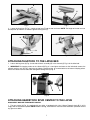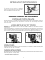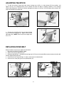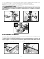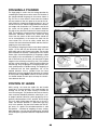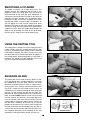
1
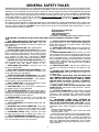
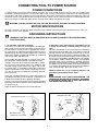
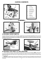
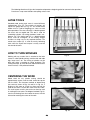
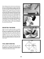
(Model LA200)
PART NO. 906122 - 06-05-02
Copyright © 2002 Delta Machinery
To learn more about DELTA MACHINERY
visit our website at: www.deltamachinery.com.
For Parts, Service, Warranty or other Assistance,
please call
ESPAÑOL: PÁGINA 23
1-800-223-7278 (In Canada call 1-800-463-3582).
INSTRUCTION MANUAL
Midi-Lathe
GENERAL SAFETY RULES
Woodworking can be dangerous if safe and proper operating procedures are not followed. As with all machinery, there
are certain hazards involved with the operation of the product. Using the machine with respect and caution will considerably lessen the possibility of personal injury. However, if normal safety precautions are overlooked or ignored, personal injury to the operator may result. Safety equipment such as guards, push sticks, hold-downs, featherboards,
goggles, dust masks and hearing protection can reduce your potential for injury. But even the best guard won’t make
up for poor judgment, carelessness or inattention. Always use common sense and exercise caution in the workshop.
If a procedure feels dangerous, don’t try it. Figure out an alternative procedure that feels safer. REMEMBER: Your
personal safety is your responsibility.
This machine was designed for certain applications only. Delta Machinery strongly recommends that this machine not
be modified and/or used for any application other than that for which it was designed. If you have any questions relative to a particular application, DO NOT use the machine until you have first contacted Delta to determine if it can or
should be performed on the product.
Technical Service Manager
Delta Machinery
4825 Highway 45 North
Jackson, TN 38305
(IN CANADA: 505 SOUTHGATE DRIVE, GUELPH, ONTARIO N1H 6M7)
WARNING: FAILURE TO FOLLOW THESE RULES MAY RESULT IN SERIOUS PERSONAL INJURY
1. FOR YOUR OWN SAFETY, READ INSTRUCTION
MANUAL BEFORE OPERATING THE TOOL. Learn the
tool’s application and limitations as well as the specific hazards peculiar to it.
2. KEEP GUARDS IN PLACE and in working order.
3. ALWAYS WEAR EYE PROTECTION. Wear safety
glasses. Everyday eyeglasses only have impact resistant
lenses; they are not safety glasses. Also use face or dust
mask if cutting operation is dusty. These safety glasses
must conform to ANSI Z87.1 requirements. NOTE:
Approved glasses have Z87 printed or stamped on them.
4. REMOVE ADJUSTING KEYS AND WRENCHES. Form
habit of checking to see that keys and adjusting wrenches
are removed from tool before turning it “on”.
5. KEEP WORK AREA CLEAN. Cluttered areas and
benches invite accidents.
6. DON’T USE IN DANGEROUS ENVIRONMENT. Don’t
use power tools in damp or wet locations, or expose them
to rain. Keep work area well-lighted.
7. KEEP CHILDREN AND VISITORS AWAY. All children
and visitors should be kept a safe distance from work area.
8. MAKE WORKSHOP CHILDPROOF – with padlocks,
master switches, or by removing starter keys.
9. DON’T FORCE TOOL. It will do the job better and be
safer at the rate for which it was designed.
10. USE RIGHT TOOL. Don’t force tool or attachment to
do a job for which it was not designed.
11. WEAR PROPER APPAREL. No loose clothing, gloves,
neckties, rings, bracelets, or other jewelry to get caught in
moving parts. Nonslip footwear is recommended. Wear protective hair covering to contain long hair.
12. SECURE WORK. Use clamps or a vise to hold work
when practical. It’s safer than using your hand and frees
both hands to operate tool.
13. DON’T OVERREACH. Keep proper footing and balance at all times.
14. MAINTAIN TOOLS IN TOP CONDITION. Keep tools
sharp and clean for best and safest performance. Follow
instructions for lubricating and changing accessories.
15. DISCONNECT TOOLS before servicing and when
changing accessories such as blades, bits, cutters, etc.
16. USE RECOMMENDED ACCESSORIES. The use of
accessories and attachments not recommended by Delta
may cause hazards or risk of injury to persons.
17. REDUCE THE RISK OF UNINTENTIONAL STARTING.
Make sure switch is in “OFF” position before plugging in
power cord. In the event of a power failure, move switch
to the “OFF” position.
18. NEVER STAND ON TOOL. Serious injury could occur if
the tool is tipped or if the cutting tool is accidentally contacted.
19. CHECK DAMAGED PARTS. Before further use of the
tool, a guard or other part that is damaged should be carefully checked to ensure that it will operate properly and perform its intended function – check for alignment of moving
parts, binding of moving parts, breakage of parts, mounting,
and any other conditions that may affect its operation. A
guard or other part that is damaged should be properly
repaired or replaced.
20. DIRECTION OF FEED. Feed work into a blade or cutter against the direction of rotation of the blade or cutter
only.
21. NEVER LEAVE TOOL RUNNING UNATTENDED.
TURN POWER OFF. Don’t leave tool until it comes to a
complete stop.
22. STAY ALERT, WATCH WHAT YOU ARE DOING, AND
USE COMMON SENSE WHEN OPERATING A POWER
TOOL. DO NOT USE TOOL WHILE TIRED OR UNDER
THE INFLUENCE OF DRUGS, ALCOHOL, OR MEDICATION. A moment of inattention while operating power tools
may result in serious personal injury.
23. MAKE SURE TOOL IS DISCONNECTED FROM
POWER SUPPLY while motor is being mounted, connected or reconnected.
24. THE DUST GENERATED by certain woods and wood
products can be injurious to your health. Always operate
machinery in well ventilated areas and provide for proper
dust removal. Use wood dust collection systems whenever
possible.
25.
WARNING: SOME DUST CREATED BY
POWER SANDING, SAWING, GRINDING, DRILLING,
AND OTHER CONSTRUCTION ACTIVITIES contains
chemicals known to cause cancer, birth defects or other
reproductive harm. Some examples of these chemicals
are:
· lead from lead-based paints,
· crystalline silica from bricks and cement and other
masonry products, and
· arsenic and chromium from chemically-treated lumber.
Your risk from these exposures varies, depending on how
often you do this type of work. To reduce your exposure
to these chemicals: work in a well ventilated area, and
work with approved safety equipment, such as those
dust masks that are specially designed to filter out microscopic particles.
2
ADDITIONAL SAFETY RULES FOR
WOOD LATHES
WARNING: FAILURE TO FOLLOW THESE RULES MAY RESULT IN SERIOUS PERSONAL INJURY.
1. DO NOT OPERATE THIS MACHINE UNTIL it is assembled and installed according to the instructions.
2. OBTAIN ADVICE from your supervisor, instructor, or
another qualified person if you are not familiar with the
operation of this machine.
3. FOLLOW ALL WIRING CODES and recommended
electrical connections.
4. ROUGH CUT THE WORKPIECE as close as possible to
the finished shape before installing it on the faceplate.
5. EXAMINE THE WORKPIECE FOR FLAWS and test glue
joints before mounting the workpiece on machine. DO
NOT mount a split workpiece or one containing a knot.
6. SECURELY FASTEN THE WORKPIECE to the faceplate
prior to faceplate turning. Use the appropriate size faceplate to properly support the workpiece. Do not let the
screw fasteners interfere with the turning tool at the finished dimension of the workpiece.
7. NEVER DRIVE THE WORKPIECE into the drive center
while the drive center is in the headstock. Set the drive
center into the workpiece with a soft mallet prior to
installing it into the headstock.
8. SNUG THE TAILSTOCK CENTER against the workpiece and lock it when turning between centers.
Lubricate the tailstock center if it is not a ball bearing
center.
9. PROPERLY ADJUST THE TOOL REST HEIGHT.
10. ADJUST THE TOOL REST so it is as close to the workpiece as possible.
11. TIGHTEN ALL CLAMP LOCKING HANDLES before
operating.
12. ROTATE THE WORKPIECE BY HAND to check clearance before turning the machine “ON”.
13. CLEAR THE LATHE BED OF ALL OBJECTS (tools,
scraps of wood, etc.) before turning the machine “ON”.
14. EXAMINE THE SET-UP CAREFULLY before turning the
machine “ON”.
15. STAND CLEAR, AND KEEP ALL OBSERVERS AND
PASSERSBY clear of rotating path of workpiece to
avoid injury from flying debris.
16. USE THE LOWEST SPEED when starting a new workpiece. NEVER EXCEED recommended speeds.
17. NEVER ADJUST THE TOOL REST while the workpiece
is turning.
18. NEVER LOOSEN THE TAILSTOCK SPINDLE or the
tailstock while workpiece is turning.
19. MOVE THE CUTTING TOOL INTO THE WORKPIECE
SLOWLY, and cut small amounts when roughing.
20. REMOVE THE TOOL REST before sanding or polishing.
21. NEVER PERFORM LAYOUT, assembly, or set-up work
on the table/work area when the machine is running.
22. TURN THE MACHINE “OFF” AND DISCONNECT
THE MACHINE from the power source before installing
or removing accessories, before adjusting or changing
set-ups, or when making repairs.
23. TURN THE MACHINE “OFF”, disconnect the machine
from the power source, and clean the table/work area
before leaving the machine. LOCK THE SWITCH IN
THE “OFF” POSITION to prevent unauthorized use.
24. ADDITIONAL INFORMATION regarding the safe and
proper operation of this machine is available from the
Power Tool Institute, 1300 Summer Avenue, Cleveland,
OH 44115-2851. Information is also available from the
National Safety Council, 1121 Spring Lake Drive,
Itasca, IL 60143-3201. Please refer to the American
National Standards Institute ANSI 01.1 Safety
Requirements for Woodworking Machines and the U.S.
Department of Labor OSHA 1910.213 Regulations.
SAVE THESE INSTRUCTIONS.
Refer to them often
and use them to instruct others.
3
CONNECTING TOOL TO POWER SOURCE
POWER CONNECTIONS
A separate electrical circuit should be used for your tools. This circuit should not be less than #12 wire and should be protected with a 20 Amp time lag fuse. If an extension cord is used, use only 3-wire extension cords which have 3-prong grounding type plugs and 3-hole receptacles which accept the tool’s plug. Before connecting the motor to the power line, make sure
the switch is in the “OFF” position and be sure that the electric current is of the same characteristics as indicated on the tool.
All line connections should make good contact. Running on low voltage will damage the motor.
WARNING: DO NOT EXPOSE THE TOOL TO RAIN OR OPERATE THE TOOL IN DAMP LOCATIONS.
MOTOR SPECIFICATIONS
Your tool is wired for 110-120 volt, 60 HZ alternating current. Before connecting the tool to the power source, make sure
the switch is in the “OFF” position.
GROUNDING INSTRUCTIONS
WARNING: THIS TOOL MUST BE GROUNDED WHILE IN USE TO PROTECT THE OPERATOR FROM
ELECTRIC SHOCK.
2. Grounded, cord-connected tools intended for use on
a supply circuit having a nominal rating less than 150
volts:
This tool is intended for use on a circuit that has an outlet that
looks like the one illustrated in Fig. A. The tool has a grounding plug that looks like the plug illustrated in Fig. A.. A temporary adapter, which looks like the adapter illustrated in Fig.
B, may be used to connect this plug to a 2-hole receptacle as
shown in Fig. B if a properly grounded outlet is not available.
The temporary adapter should be used only until a properly
grounded outlet can be installed by a qualified electrician.
The green-colored rigid ear, lug, and the like, extending from
the adapter must be connected to a permanent ground such
as a properly grounded outlet box. Whenever the adapter is
used, it must be held in place with a metal screw.
1. All grounded, cord-connected tools:
In the event of a malfunction or breakdown, grounding provides a path of least resistance for electric current to reduce
the risk of electric shock. This tool is equipped with an electric cord having an equipment-grounding conductor and a
grounding plug. The plug must be plugged into a matching
outlet that is properly installed and grounded in accordance
with all local codes and ordinances.
Do not modify the plug provided - if it will not fit the outlet,
have the proper outlet installed by a qualified electrician.
Improper connection of the equipment-grounding conductor can result in risk of electric shock. The conductor with
insulation having an outer surface that is green with or without yellow stripes is the equipment-grounding conductor. If
repair or replacement of the electric cord or plug is necessary, do not connect the equipment-grounding conductor
to a live terminal.
NOTE: In Canada, the use of a temporary adapter is not
permitted by the Canadian Electric Code.
Check with a qualified electrician or service personnel if the
grounding instructions are not completely understood, or if
in doubt as to whether the tool is properly grounded.
WARNING: IN ALL CASES, MAKE CERTAIN THE
RECEPTACLE IN QUESTION IS PROPERLY GROUNDED.
IF YOU ARE NOT SURE, HAVE A QUALIFIED ELECTRICIAN CHECK THE RECEPTACLE.
Use only 3-wire extension cords that have 3-prong grounding
type plugs and 3-hole receptacles that accept the tool’s plug,
as shown in Fig. A.
Repair or replace damaged or worn cord immediately.
HOLES
GROUNDED OUTLET BOX
GROUNDED OUTLET BOX
GROUNDING
MEANS
CURRENT
CARRYING
PRONGS
ADAPTER
GROUNDING BLADE
IS LONGEST OF THE 3 BLADES
HOLES
Fig. A
Fig. B
4
EXTENSION CORDS
MINIMUM GAUGE EXTENSION CORD
RECOMMENDED SIZES FOR USE WITH STATIONARY ELECTRIC TOOLS
Ampere
Rating
Use proper extension cords. Make sure your extension
cord is in good condition and is a 3-wire extension cord
which has a 3-prong grounding type plug and a 3-hole
receptacle which will accept the tool’s plug. When using
an extension cord, be sure to use one heavy enough to
carry the current of the tool. An undersized cord will
cause a drop in line voltage, resulting in loss of power
and overheating. Fig. C shows the correct gauge to use
depending on the cord length. If in doubt, use the next
heavier gauge. The smaller the gauge number, the heavier the cord.
Volts
Total Length
of Cord in Feet
Gauge of
Extension Cord
0-6
0-6
0-6
0-6
120
120
120
120
up to 25
25-50
50-100
100-150
18 AWG
16 AWG
16 AWG
14 AWG
6-10
6-10
6-10
6-10
120
120
120
120
up to 25
25-50
50-100
100-150
18 AWG
16 AWG
14 AWG
12 AWG
10-12
10-12
10-12
10-12
120
120
120
120
up to 25
25-50
50-100
100-150
16 AWG
16 AWG
14 AWG
12 AWG
12-16
12-16
12-16
120
120
120
up to 25
25-50
14 AWG
12 AWG
GREATER THAN 50 FEET NOT RECOMMENDED
Fig. C
OPERATING INSTRUCTIONS
FOREWORD
Delta Model LA200 is a compact and stable wood lathe with a powerful 1/2 HP, 1725 rpm motor. This lathe will turn
objects up to 10" in diameter over the bed and 6" in diameter over the tool rest base with a maximum distance
between centers of 37" with the optional bed extension.
UNPACKING AND CLEANING
This machine is shipped complete in one container. Carefully remove the contents from the shipping container. Remove the protective coating from the lathe bed and all unpainted parts. This coating may be
removed with a soft cloth moistened with kerosene (do not use acetone, gasoline or lacquer thinner). After
cleaning, cover the lathe bed with a good quality paste wax.
NOTICE: THE MANUAL COVER PHOTO ILLUSTRATES THE CURRENT PRODUCTION MODEL. ALL OTHER ILLUSTRATIONS ARE REPRESENTATIVE ONLY
AND MAY NOT DEPICT THE ACTUAL COLOR, LABELING OR ACCESSORIES
AND MAY BE INTENDED TO ILLUSTRATE TECHNIQUE ONLY.
5
CARTON CONTENTS
10
1
9
6
5
2
8
7
3
4
1.
Lathe
2.
Tailstock
3.
Live Center
4.
Knockout Bar
5.
Tool Rest Base
6.
Spur Center
7.
Tool Rest
8.
Spacer
9.
Face Plate
10.
Spanner Wrench
Fig. 1
ASSEMBLY
B
C
D
D
A
Fig. 3
Fig. 2
ATTACHING ON/OFF SWITCH
To prevent damage to the on/off switch, the lathe is shipped with the switch bracket detached from the rear of the
headstock. Attach the switch bracket in the upright position. Align two holes in switch bracket (A) Fig. 2 with the two
holes (B) at the rear of the headstock (C), and attach the switch bracket (A) to the machine with two pan head screws
(D) and lockwashers (Fig. 3).
B
B
D
A
C
Fig. 4
A
Fig. 5
ATTACHING TOOL REST TO THE LATHE BED
1. Loosen locking lever (A) Fig. 4 and slide tool rest base (B) into the channel of lathe bed (C). NOTE: If the tool rest
base will not slide easily inside the channel of the lathe bed, turn the tool rest base over and loosen locknut (D) Fig. 4,
located at the underside of the tool rest base. Tighten locking lever (A) Fig. 5 to clamp the tool rest base (B) securely
on the lathe bed.
2. IMPORTANT: If clamping action on the tool rest base (B) Fig. 5 is too tight or too loose on the lathe bed, remove the base and
turn nut (D) Fig. 6 clockwise to tighten clamping action, or counterclockwise to loosen clamping action. Attach the tool rest base on
the lathe bed.
6
D
E
F
Fig. 6
Fig. 7
3. Loosen locking lever (E) Fig. 7, and insert tool rest (F) into the tool rest base. NOTE: The height of the tool rest can
be adjusted up or down as needed. Tighten locking lever (E).
B
D
A
C
Fig. 8
Fig. 9
ATTACHING TAILSTOCK TO THE LATHE BED
1. Loosen locking lever (A) Fig. 9, and slide tailstock assembly (B) in the channel (C) Fig. 8 of the lathe bed.
2. IMPORTANT: If clamping action on the tailstock (B) Fig. 9 is too tight or too loose on the lathe bed, remove the
tailstock and turn nut (D) Fig. 8 clockwise to tighten clamping action, or counterclockwise to loosen clamping action.
Attach the tailstock on the lathe bed and tighten locking lever (A) Fig. 9.
A
B
Fig. 10
ATTACHING HEADSTOCK SPUR CENTER TO THE LATHE
DISCONNECT MACHINE FROM POWER SOURCE.
1. The spur center (A) Fig. 10, supplied with your lathe, is equipped with a No. 2 Morse Tapered shank (B). It will fit
snugly into the headstock spindle. NOTE: Before inserting, clean both the shank and the headstock spindle to remove
any grease or debris.
7
A
2. Use the knockout bar (C) Fig. 11 through the hole in
the opposite end of the spindle to remove the spur center (A) Fig. 11 from the headstock spindle. NOTE: Be
careful of the sharp points on the shank spur center.
C
IMPORTANT: NEVER DRIVE THE WORKPIECE INTO
THE SPUR CENTER WHEN IT IS MOUNTED IN THE
HEADSTOCK. See the “OPERATIONS” section of this
manual.
Fig. 11
ATTACHING LIVE CENTER TO THE TAILSTOCK
DISCONNECT MACHINE FROM POWER SOURCE.
The tailstock live center (A) Fig. 12, supplied with your lathe, is equipped with a No. 2 Morse Taper shank (B) and is
inserted into the tailstock spindle (C). To remove the live center (A) Fig. 13 from the tailstock spindle, loosen lock knob
(C) and rotate handwheel (D) to move spindle (B) back into the tailstock body. This action will push the live center (A)
out of the spindle (B). Use the knockout bar through the hollow tailstock (F) to remove the center point (E).
A
B
C
E
F
A
B
D
C
Fig. 12
Fig. 13
ATTACHING FACEPLATE TO THE HEADSTOCK
To use the faceplate for inboard turning, mount the faceplate to the headstock spindle in the following manner (shown
without workpiece for clarity).
1. DISCONNECT MACHINE FROM POWER SOURCE.
2. Install spacer (A) Fig. 14 on the headstock spindle (B).
3. Thread faceplate (C) Fig. 15 on spindle. Insert knockout bar (D) into hole in spindle to keep it from turning, and
tighten faceplate (C) with supplied wrench (B) on flats.
A
D
B
B
C
C
Fig. 15
Fig. 14
8
FASTENING LATHE TO SUPPORTING SURFACE
The wood lathe must be fastened to a supporting
surface. Four mounting holes (three of which are shown
(A) Fig. 16 are provided in the base of the lathe.
A
A
Fig. 16
OPERATING CONTROLS AND ADJUSTMENTS
STARTING AND STOPPING THE LATHE
The on/off switch (A) Fig. 17 is located on the bracket (B) attached earlier to the rear of the headstock. To turn the
switch “ON”, move the switch (A) up to the “ON” position. To turn the switch “OFF”, move the toggle switch (A) down
to the “OFF” position.
LOCKING SWITCH IN THE “OFF” POSITION
IMPORTANT: When the machine is not in use, the switch should be locked in the “OFF” position to prevent
unauthorized use.
To lock, grasp the toggle (C) Fig. 18, and pull it out of the switch (A).When the safety toggle (C) Fig. 18 is removed, the
switch will not operate. However, should the safety toggle be removed while the wood lathe is operating, the switch
can be turned “OFF” once, but cannot be restarted without inserting the safety toggle (C) back into the switch.
C
A
A
B
Fig. 18
Fig. 17
SPINDLE SPEEDS
Depending on the position of the belt on the motor and spindle pulleys, the wood lathe is capable of providing speeds
of 500, 800, 1250, 1800, 2650, and 3700 RPM.
CHANGING SPINDLE SPEEDS
The wood lathe features a six-step motor pulley and spindle pulley to provide the different spindle speeds for particular
wood turning applications. To change speeds:
1.
Disconnect machine from power source.
9
2. Open access doors (A) and (B) Fig. 19 to gain access to motor pulley (C) Figs. 20 and 20A, and spindle pulley (D)
Figs. 20 and 21.
3. Loosen locking lever (E) Fig. 20 to relieve tension on the motor pulley. Raise lever (F) Fig. 20, and tighten locking
lever (E) to enable the drive belt to be moved on the pulleys.
IMPORTANT: A speed and belt position chart (G) Figs. 20 and 21 is located on the inside of the access door (A) to
help position the belt (H) Fig. 21 correctly on the pulleys.
4. While holding lever (F) Fig. 20, loosen locking lever (E).to release tension on the motor. Lower the motor. (NOTE:
The weight of the motor will provide proper tension on the drive belt.) Tighten locking lever (E).
G
D
A
A
C
B
E
F
Fig. 20
Fig. 19
D
C
G
Fig. 20A
Fig. 21
ADJUSTING TOOL REST
For most applications, the tool rest should be positioned as close as possible to the work and approximately 1/8” above
the work centerline.
1. To position the tool rest base (A) Fig. 22 along the lathe bed, loosen locking lever (B), slide the tool rest base to the
desired position, and tighten lever (B).
2. To adjust the height of the tool rest (C) Fig. 22, loosen lever (D), raise or lower tool rest and tighten lever (D).
3. The clamping device on the tool rest base can be adjusted by turning the tool rest support (A) Fig. 23 over and adjusting nut (E) clockwise to tighten or counterclockwise to loosen the clamping action.
A
C
E
A
D
B
Fig. 23
Fig. 22
10
ADJUSTING TAILSTOCK
1. To slide the tailstock along lathe bed, loosen locking lever (A) Fig. 24, slide tailstock (B) into position, and
tighten lever (A). The clamping device for the tailstock has been set prior to shipping. However, if the clamping
action needs adjustment, remove the tailstock and tighten (or loosen) nut (C) Fig. 25 on the bottom of the tailstock. Reattach the tailstock to the lathe bed.
B
A
C
Fig. 24
Fig. 25
E
2. To move the ram (D) Fig. 26, in or out, loosen locking
lever (E) and turn handwheel (F). Tighten lever (E) after
adjusting ram (D). NOTE: Total ram (D) travel ranges from
0 to 1-1/2".
F
D
Fig. 26
REPLACING DRIVE BELT
When it becomes necessary to replace the drive belt:
1. Disconnect machine from power source.
2. Open the two access doors (A) Fig. 27.
3. Hold the handle (B) Fig. 27, and loosen the locking lever (C). Pull up on the handle (B) to remove tension on the drive belt
and then tighten locking lever (C).
4. Loosen the two set screws (D) Figs. 27 and 28, and remove the handwheel (E).
5. Loosen the set screw (G) Fig. 28 on the spindle pulley (H).
D
A
G
D
E
D
E
D
B
A
H
C
Fig. 28
Fig. 27
11
6. Use a soft-tipped mallet (J) Fig. 29 to carefully tap the spindle shaft (K) thru the bearing. Tap it far enough to move
the spindle shaft to the right to remove the spindle pulley (H), and spindle shaft (K), (Fig. 30).
IMPORTANT: Be careful not to drop the metal key (M) Fig. 30 into the hub of the spindle pulley (H).
7. Remove the drive belt (A) Fig. 31 from the motor pulley (B).
8. Replace the drive belt and the spindle assembly in reverse order. Apply proper tension to the drive belt. Refer to
section “CHANGING SPINDLE SPEEDS”.
9. IMPORTANT: When attaching the spindle and handwheel, make certain that the set screws in the spindle pulley are
tightened against the flat surface of the spindle. Check the spindle pulley to see if it is aligned with the motor pulley.
Adjust if necessary.
K
H
M
K
H
L
J
Fig. 29
Fig. 30
A
B
Fig. 31
ATTACHING BED EXTENSION
The total bed length of the lathe (center to center) can be increased to 37" by purchasing and installing an accessory
bed extension. To attach the bed extension to the lathe:
1. Align the two holes in the end of the lathe bed (A) Fig. 32 with the two holes (B in the end of bed extension ) and
fasten with two M10 x 40 x 1-1/2" hex head screws, lockwashers, and flat washers (C) using the supplied wrench (D).
2. IMPORTANT: Before tightening screws, use a straight edge (E) Fig. 33 to be certain that the lathe bed (A) is flush
with the bed extension (B). This action will allow the tailstock to move freely along both beds.
E
A
D
B
A
C
B
Fig. 32
Fig. 33
12
The following directions will give the inexperienced operator a beginning point for common lathe operations.
Practice on scrap material before attempting serious work.
LATHE TOOLS
Standard wood turning tools come in several different
configurations (Fig. A1). The majority of turnings will
require the gouge tool (A) Fig. A1. This round nosed
hollow chisel is used for roughing cuts, cove cuts and
other operations. The skew chisel (B) is a double-ground
flat chisel, with an angled end. This tool is used for
smoothing cylinders, for cutting shoulders, beads, veegrooves, etc. The parting tool (C) is a double-ground
chisel, used for cutting-off, or for making straight
incisions or sizing cuts to any required diameter. The
round nose scraper (D) is used for mostly hollowing
work, while the square-end scraper is mainly used for
the outside of bowls.
E
C
A
B
HOW TO TURN SPINDLES
Fig. A1
Working with any material that is attached to the lathe
centers is called spindle turning, used for chair and table
legs, lamp stems, etc. The turning of spindles can be
done with either a scraping or cutting technique. The
cutting technique, by virtue of faster wood removal and a
cleaner surface, is the preferred method.
CENTERING THE WORK
Wood stock for any spindle turning should be
approximately square, and the ends should be square
with the sides. Two common methods of determining
the center are shown in Figs. A2 and A3. In Fig. A2, a
distance a little more or a little less than one-half the
width of the stock is set off from each of the four sides.
The small square set off in the center can then be used
in marking the true center. The diagonal method, Fig. A3,
consists of drawing lines from corner to corner, with the
intersection marking the center of the work.
Fig. A2
Fig. A3
13
D
A
After marking each end, mark the true center with a
punch awl or dividers (Fig. A4). If the stock is hardwood,
the centers should be drilled to a depth of about 1/8”.
The spur or live center is then placed against one end of
the work and seated by striking with a mallet (Fig. A5). In
hardwood, make a starting seat for the spur center by
sawing on the diagonal lines, and drilling a small hole at
the intersection. After driving the center, hold the center
and the work together and fit both immediately to headstock spindle. If you are not using a ball bearing center,
the end of work at tailstock center should be oiled. Place
the lubricant on the wood either before or after it is put
on the lathe. Many turners use beeswax, tallow, or a
wax-and-oil mixture as a lubricant. A ball bearing center
is ideal because it eliminates lubricating. If the work is to
be removed from the lathe before completion, an index
mark should be made as a guide for re-centering (Fig.
A6). A permanent indexer can be made by grinding off
one corner of one of the spurs.
Fig. A4
Fig. A5
MOUNTING THE WORK
Mount the work by moving the tailstock to a position
about 1" or 1-1/2" from the end of the workpiece, and
locking it in this position. Advance the tailstock center
by turning the feed handle until the center cup makes
contact with the work. Do not support the work on the
center pin alone. Always have the rim of the center cup
imbedded at least 1/8" into the work. Continue to
advance the center while slowly rotating the work by
hand. After it becomes difficult to turn the work, slack
off on the feed about one-quarter turn and lock the tailstock spindle.
Fig. A6
TOOL REST POSITION
Mount the tool rest in place about 1/8" away from
the work and 1/8" above the work centerline (Fig. A7.)
This position may be varied to suit the work and the
operator. Place a guide mark on the tool rest shank as
an aid to quick and accurate resetting.
Fig. A7
14
ROUGHING A CYLINDER
The large gouge is used in the first turning operation by
smoothing the sharp corners of the work. Run the lathe at
low speed and hold the gouge in the manner shown in
Fig. A8. The cut starts about 2 inches from the tailstock
end and continues from this point to the end of the tailstock. Make the second pass beginning about 2" or 3" to
the left of the first cut. Advance again toward the tailstock,
and merge with the previous cut. Toward the end of the
live center, roll the gouge in the opposite direction
(Fig. A9) to carry the final cut off the live center end of the
work. The roughing cut should not be carried out with one
continuous movement, because this would tear long
slivers from the corners of the work. Neither should the
cut be started directly at the end of the stock for the
same reason. The cut can be safely carried from the
center of the stock toward and off either end once the first
roughing cuts have been made.
Fig. A8
The position of the gouge involves two or three important
angles. (1) The tool may be advanced along the work
either from right to left or from left to right. Left to right
(from headstock to tailstock) is preferred since this action
throws chips clear of the operator. (2) The gouge is rolled
over slightly in the same direction it is advancing. (3) The
tool is held well up on the work, with the bevel or grind
tangent to the revolving surface (Fig. A10). This position
will give a clean shearing cut. When pushed straight into
the work (Fig. A10), the gouge has a scraping action, (normally a poor practice in spindle turning). The roughing cut
is continued until the work approaches 1/8" of the
required diameter. Once a cylindrical form has been
obtained, the turning speed can be moved to the second
or third speed setting. NOTE: Continue to move the tool
rest inward toward the work piece to keep the safe distance between the two.
Fig. A9
Fig. A10
POSITION OF HANDS
While turning, the hand that holds the tool handle
should be in a natural position. This hand provides the
leverage for the tool by either moving in toward the
chisel or moving out. The position of the tool rest hand is
more a matter of individual preference, rather than a “set”
or “proper” position. However, a palm-up grip (Fig. A11) is
generally considered best. In this position, the first finger
acts as a guide, sliding along the tool rest as the cut is
made. The alternate position is a palm-down grip (Fig.
A12). In this position, the heel of the hand or the little finger serves as a guide. The palm-down position is solid
and positive – excellent for roughing or heavy cutting.
Most beginners start with the palm-down grip, switching
later to the palm-up position for better manipulation of the
chisel.
Fig. A11
Fig. A12
15
SMOOTHING A CYLINDER
To smooth a cylinder, use a large skew chisel. This
requires practice, but experience with this tool is very
important. Place the cutting point near the center of
chisel and high on the work (Fig. A13). Sometimes, in
striving for a certain position in relation to the work, the
beginner will often overlook this all-important point.
Raising the handle will increase the depth of cut while
lowering the handle, of course, does the opposite. As
with the gouge, the skew can be advanced in either
direction. The center of the skew toward the heel does
the actual cutting. The back portion of the grind or bevel
supports the tool, while the handle-hand controls the
depth of cut by rocking the chisel on this pivot point.
Because of this, keep the skew bevel perfectly flat.
Fig. A13
USING THE PARTING TOOL
The parting tool is perhaps the easiest turning chisel to
handle. Simply push this scraping tool into the work
(Fig. A14). A somewhat better cutting action is obtained
if the handle is held low. This tool is, in many cases, held
with one hand while the other hand holds the calipers in
the cutting groove. When parting tool cuts are deep, a
clearance cut should be made alongside the first cut
(Fig. A15) to prevent burning the tool point.
Fig. A14
Fig. A15
SQUARING AN END
The parting tool can be used to quickly square an end.
Since the parting tool is a rough cutter, the cut can then
be smoothed by using the skew. However, the whole
operation can be done with the skew. In using the skew,
make your first cut a nicking cut with the toe of the skew
(Fig. A16). A deep cut here could burn the chisel, so
a clearance cut is made by inclining the skew away from
the first cut and pushing the tool into the work. This
procedure of side cut and clearance cut is continued as
often as needed. NOTE: While the skew can be pushed
into the wood in any direction, the cutting edge itself
must be inclined a little away from this plane .If the full
cutting edge of skew bears against the cut surface, the
tool will have a tendency to run. See Fig. A17 for the
proper way to make the cut. Push the chisel straight into
the work, and incline the cutting edge away from the cut
surface. Use only the extreme end of the toe for this cut.
This important principle in skew handling will be used
repeatedly in making shoulders, beads and vee cuts.
Fig. A16
Fig. A17
16
CUTTING A SHOULDER
Use the parting tool first to reduce the wood to within
1/16” of the required shoulder and diameter (Fig. A18).
Clean the waste stock out with the gouge (Fig. A19),
then use the skew for the actual cutting of the shoulder
(Fig. A20), which is a duplication of squaring an end. The
skew then makes the horizontal cut, but in a different
manner from plain cylinder work. If the shoulder is long,
use the ordinary skew position for the outer portion of
the cut. At the angle between the horizontal and vertical
cuts, the heel of the chisel moves into a position tangent
between the skew and the cylinder (Fig. A21). In this
position, raise the handle of the chisel slightly to allow it
to cut while the tool moves along the rest. Use a very
light cut to produce smooth work. The heel of the skew
can be used for making the entire cut, if desired, but the
cut, whether in this position or any other position, should
not be picked up directly at the end of the stock.
Horizontal cuts started directly from the end of the work
will have a tendency to bite into the wood, often ruining
the entire piece. Always run off the end and not into it.
Where a very short shoulder makes this impossible, use
the skew in a flat scraping position. If the cutting technique is used, engage only with the heel of skew in a
very light cut.
Fig. 49
Fig. A18
Fig. A19
Fig. A20
Fig. A21
CUTTING SMALL BEADS
Fig. A22
Beads can be scraped or cut. Using the spear chisel is
the easiest method of scraping, and works to best
advantage on beads separated by parting tool cuts
(Fig. A22). Scraping is slower than cutting and is not as
clean, but it has the advantage of protecting the work
from long gashes.
Cutting beads quickly and accurately with the small
skew is one of the most difficult lathe operations.
Various working methods can be used . The first cut is a
vertical incision at the point where the two curved surfaces will eventually come together. Make this cut with
either heel or toe of skew. Fig. A23 shows the use of the
toe. Place the skew at right angles to the work . The chisel is flat on its side at the start, and is evenly rotated
through the successive stages of the cut (Figs. A24,
A25, and A26). At the same time, the chisel is pulled
slightly backward to maintain the cutting point. The
entire cut is made with the heel of chisel. The opposite
side of the bead is cut in the same manner, one cut
serving to produce the full shape in each instance. This
action produces beads that are beautifully smooth and
polished, and the technique is well worth mastering.
17
Fig. A23
Fig. A24
Fig. A25
Fig. A26
VEE GROOVES
Cutting the vee groove demands much the same
technique as the bead, except the skew is hinged
straight into the work without rotation (Fig. A27). Only
one-half of the vee is made at a time, and one, two, or
more cuts may be needed on each side to obtain the
desired shape. As in all cutting with the skew, the bevel
next to the cut must be used as a fulcrum. Be careful not
to allow full edge of the chisel to catch and cause a run.
Vee grooves can also be made with the toe of the skew,
in the same manner as squaring an end.
Fig. A27
LONG CUTS
Long cuts are usually either convex or straight-tapered
surfaces. With a convex surface, the method used in
making the finishing cut is shown in Fig. A28. The gouge
is turned on the tool rest so that it will be inclined in the
direction that it will move. The grind is tangent to the
work, and the center point of the cutting edge is the
contact point with the wood. As the cut progresses
toward and around the end of the curve, the handle is
gradually raised and swiveled to the right (Fig. A29) in
order to maintain the tangency between the grind and
the surface being cut .
Fig. A28
Fig. A29
Fig. A30
Figs. A30 and A31 show the cutting of a long taper with
a skew. The operation differs from smoothing a cylinder
only at the start of the cut. The starting cut should be
made with the heel (Fig. A30) to prevent the tool from
digging into the work. As the tool moves down the work,
the chisel can be pulled back to allow the center point of
the cutting edge to cut. However, the full taper can be
made with the heel. Be careful not to cut too deeply at
the center of the taper. The direction of cutting is always
downhill.
Fig. A31
COVE CUTS
Second to forming a perfect bead, the cove or concave
cut is the most difficult to master. This cut is made with
the gouge, where the size of the tool depends on the
size of the cut. Push the gouge directly into the work to
remove the surplus stock (Fig. A32).
Fig. A32
18
The gouge is placed on edge on the tool rest so that the
grind of the chisel forms an approximate right angle
with the work (Fig. A33). The chisel contacts the work at
the center of the cutting edge. Hold the tool so that the
centerline of the gouge is pointing directly toward the
center of the revolving stock. This starting position is
important to prevent the gouge from running along the
surface of the work.
From the starting position, push the gouge into the
revolving stock, and roll the tool on the rest. A triple
action takes place here. (1) The chisel will roll to follow
the shape of the cut, (2) the handle will drop slightly
so that the portion already cut will force the lip of the
chisel sideways and, (3) the chisel will be pushed
forward so that at the end of the cut, Fig. A34, it will be
well up on the work and tangent with the cut surface.
Make only one-half of the cut at a time, then reverse the
chisel to cut the other half. The occasional turner should
make cove cuts with a scraping technique, using either
the small gouge or round nose chisel.
Fig. A33
SQUARE SECTIONS
Fig. A34
Fig. A35
When the turning has a square section, joint the stock
before turning. Good centering is essential since any
error will show at the shoulder where the round meets
the square. Turning of the shoulder from square to
round can be done in various ways (See Figs. A35, A36,
A37, and A38). If the parting tool is sharp, the nicking cut
with skew (Fig. A37) can be omitted. The final trimming
operation (Fig. A38) can be done with either the skew,
spear chisel, or gouge, and is a scraping operation.
While the shoulder can be cut with the same technique
used for cutting a bead, the simpler scraping method
pictured does clean work and is easier to do.
Fig. A36
Fig. A37
Fig. A38
19
FACEPLATE TURNING
Mount turnings that cannot be worked between centers on a faceplate. The greater part of this
type of turning is done with the faceplate mounting, although there are a number of jobs which
require special chucks. All cutting in faceplate work is done by scraping. Any attempt to use a
cutting technique on the edge grain of large work will result in a hogging, gouging cut which may
jerk the chisel out of the hands of the operator. Use a band saw on all work to roughly cut the turning area slightly oversized to eliminate heavy roughing cuts in turning.
MOUNTING WORK
TO FACEPLATE
Fig. A39 shows direct mounting to the 3" faceplate
along with attaching to the backing block. Because of
the ease of setting up, use this mounting whenever the
work permits. Hold larger pieces in the same way by
using the 6" faceplate. When normal screw-fastenings
interfere, mount the work on a backing block (Fig. A39).
When screws are not permissible at all, glue the work to
the backing block by fitting a sheet of paper at the joint
to allow later separation without damaging the wood.
Some work can be screwed or nailed from the face side
into backing block. Mount work less than 3” in diameter
on the single screw center (Fig. A40).
Fig. A39
Fig. A40
20
NOTES
21
ACCESSORIES
A complete line of accessories is available from your Delta Supplier, Porter-Cable • Delta Factory Service Centers,
and Delta Authorized Service Stations. Please visit our Web Site www.deltamachinery.com for a catalog or
for the name of your nearest supplier.
WARNING: Since accessories other than those offered by Delta have not been tested
with this product, use of such accessories could be hazardous. For safest operation, only
Delta recommended accessories should be used with this product.
PARTS, SERVICE OR WARRANTY ASSISTANCE
All Delta Machines and accessories are manufactured to high quality standards and are serviced by a network
of Porter-Cable • Delta Factory Service Centers and Delta Authorized Service Stations. To obtain additional
information regarding your Delta quality product or to obtain parts, service, warranty assistance, or the location of the nearest service outlet, please call 1-800-223-7278 (In Canada call 1-800-463-3582).
Two Year Limited Warranty
Delta will repair or replace, at its expense and at its option, any Delta machine, machine part, or machine accessory which
in normal use has proven to be defective in workmanship or material, provided that the customer returns the product prepaid to a Delta factory service center or authorized service station with proof of purchase of the product within two years
and provides Delta with reasonable opportunity to verify the alleged defect by inspection. Delta may require that electric
motors be returned prepaid to a motor manufacturer’s authorized station for inspection and repair or replacement. Delta
will not be responsible for any asserted defect which has resulted from normal wear, misuse, abuse or repair or alteration
made or specifically authorized by anyone other than an authorized Delta service facility or representative. Under no circumstances will Delta be liable for incidental or consequential damages resulting from defective products. This warranty
is Delta’s sole warranty and sets forth the customer’s exclusive remedy, with respect to defective products; all other warranties, express or implied, whether of merchantability, fitness for purpose, or otherwise, are expressly disclaimed by Delta.
Printed in U.S.A.
22
PORTER-CABLE • DELTA SERVICE CENTERS
(CENTROS DE SERVICIO DE PORTER-CABLE • DELTA)
Parts and Repair Service for Porter-Cable • Delta Machinery are Available at These Locations
(Obtenga Refaccion de Partes o Servicio para su Herramienta en los Siguientes Centros de Porter-Cable • Delta)
ARIZONA
Tempe 85282 (Phoenix)
2400 West Southern Avenue
Suite 105
Phone: (602) 437-1200
Fax: (602) 437-2200
CALIFORNIA
Ontario 91761 (Los Angeles)
3949A East Guasti Road
Phone: (909) 390-5555
Fax: (909) 390-5554
San Leandro 94577 (Oakland)
3039 Teagarden Street
Phone: (510) 357-9762
Fax: (510) 357-7939
COLORADO
Arvada 80003 (Denver)
8175 Sheridan Blvd., Unit S
Phone: (303) 487-1809
Fax: (303) 487-1868
FLORIDA
Davie 33314 (Miami)
4343 South State Rd. 7 (441)
Unit #107
Phone: (954) 321-6635
Fax: (954) 321-6638
Tampa 33609
4538 W. Kennedy Boulevard
Phone: (813) 877-9585
Fax: (813) 289-7948
GEORGIA
Forest Park 30297 (Atlanta)
5442 Frontage Road,
Suite 112
Phone: (404) 608-0006
Fax: (404) 608-1123
ILLINOIS
Addison 60101 (Chicago)
400 South Rohlwing Rd.
Phone: (630) 424-8805
Fax: (630) 424-8895
Woodridge 60517 (Chicago)
2033 West 75th Street
Phone: (630) 910-9200
Fax: (630) 910-0360
MARYLAND
Elkridge 21075 (Baltimore)
7397-102 Washington Blvd.
Phone: (410) 799-9394
Fax: (410) 799-9398
MASSACHUSETTS
Braintree 02185 (Boston)
719 Granite Street
Phone: (781) 848-9810
Fax: (781) 848-6759
Franklin 02038 (Boston)
Franklin Industrial Park
101E Constitution Blvd.
Phone: (508) 520-8802
Fax: (508) 528-8089
MICHIGAN
Madison Heights 48071 (Detroit)
30475 Stephenson Highway
Phone: (248) 597-5000
Fax: (248) 597-5004
MINNESOTA
Minneapolis 55429
5522 Lakeland Avenue North
Phone: (763) 561-9080
Fax: (763) 561-0653
Cleveland 44125
8001 Sweet Valley Drive
Unit #19
Phone: (216) 447-9030
Fax: (216) 447-3097
MISSOURI
North Kansas City 64116
1141 Swift Avenue
P.O. Box 12393
Phone: (816) 221-2070
Fax: (816) 221-2897
OREGON
Portland 97230
4916 NE 122 nd Ave.
Phone: (503) 252-0107
Fax: (503) 252-2123
St. Louis 63119
7574 Watson Road
Phone: (314) 968-8950
Fax: (314) 968-2790
PENNSYLVANIA
Willow Grove 19090
520 North York Road
Phone: (215) 658-1430
Fax: (215) 658-1433
NEW YORK
Flushing 11365-1595 (N.Y.C.)
175-25 Horace Harding Expwy.
Phone: (718) 225-2040
Fax: (718) 423-9619
NORTH CAROLINA
Charlotte 28270
9129 Monroe Road, Suite 115
Phone: (704) 841-1176
Fax: (704) 708-4625
OHIO
Columbus 43214
4560 Indianola Avenue
Phone: (614) 263-0929
Fax: (614) 263-1238
TEXAS
Carrollton 75006 (Dallas)
1300 Interstate 35 N, Suite 112
Phone: (972) 446-2996
Fax: (972) 446-8157
Houston 77055
West 10 Business Center
1008 Wirt Road, Suite 120
Phone: (713) 682-0334
Fax: (713) 682-4867
WASHINGTON
Auburn 98001(Seattle)
3320 West Valley HWY, North
Building D, Suite 111
Phone: (253) 333-8353
Fax: (253) 333-9613
Authorized Service Stations are located in many large cities. Telephone 800-438-2486 or 731-541-6042 for assistance locating one.
Parts and accessories for Porter-Cable·Delta products should be obtained by contacting any Porter-Cable·Delta Distributor, Authorized
Service Center, or Porter-Cable·Delta Factory Service Center. If you do not have access to any of these, call 800-223-7278 and you will
be directed to the nearest Porter-Cable·Delta Factory Service Center. Las Estaciones de Servicio Autorizadas están ubicadas en muchas
grandes ciudades. Llame al 800-438-2486 ó al 731-541-6042 para obtener asistencia a fin de localizar una. Las piezas y los accesorios
para los productos Porter-Cable·Delta deben obtenerse poniéndose en contacto con cualquier distribuidor Porter-Cable·Delta, Centro
de Servicio Autorizado o Centro de Servicio de Fábrica Porter-Cable·Delta. Si no tiene acceso a ninguna de estas opciones, llame al
800-223-7278 y le dirigirán al Centro de Servicio de Fábrica Porter-Cable·Delta más cercano.
CANADIAN PORTER-CABLE • DELTA SERVICE CENTERS
ALBERTA
Bay 6, 2520-23rd St. N.E.
Calgary, Alberta
T2E 8L2
Phone: (403) 735-6166
Fax: (403) 735-6144
BRITISH COLUMBIA
8520 Baxter Place
Burnaby, B.C.
V5A 4T8
Phone: (604) 420-0102
Fax: (604) 420-3522
MANITOBA
1699 Dublin Avenue
Winnipeg, Manitoba
R3H 0H2
Phone: (204) 633-9259
Fax: (204) 632-1976
ONTARIO
505 Southgate Drive
Guelph, Ontario
N1H 6M7
Phone: (519) 836-2840
Fax: (519) 767-4131
QUÉBEC
1515 ave.
St-Jean Baptiste,
Québec, Québec
G2E 5E2
Phone: (418) 877-7112
Fax: (418) 877-7123
1447, Begin
St-Laurent, (Montréal),
Québec
H4R 1V8
Phone: (514) 336-8772
Fax: (514) 336-3505
The following are trademarks of PORTER-CABLE·DELTA (Las siguientes son marcas registradas de PORTER-CABLE S.A.): Auto-Set®, BAMMER®, B.O.S.S.®, Builder’s Saw®, Contractor’s Saw®, Contractor’s Saw II™, Delta®, DELTACRAFT®, DELTAGRAM™, Delta Series 2000™,
DURATRONIC™, Emc²™, FLEX®, Flying Chips™, FRAME SAW®, Homecraft®, INNOVATION THAT WORKS®, Jet-Lock®, JETSTREAM®,
‘kickstand®, LASERLOC®, MICRO-SET®, Micro-Set®, Midi Lathe™, MORTEN™, NETWORK™, OMNIJIG®, POCKET CUTTER®, PORTABAND®, PORTA-PLANE®, PORTER-CABLE®&(design), PORTER-CABLE®PROFESSIONAL POWER TOOLS, Posi-Matic®, Q-3®&(design),
QUICKSAND®&(design), QUICKSET™, QUICKSET II®, QUICKSET PLUS™, RIPTIDE™&(design), SAFE GUARD II®, SAFE-LOC®, Sanding
Center®, SANDTRAP®&(design), SAW BOSS®, Sawbuck™, Sidekick®, SPEED-BLOC®, SPEEDMATIC®, SPEEDTRONIC®, STAIR EASE®, The
American Woodshop®&(design), The Lumber Company®&(design), THE PROFESSIONAL EDGE®, THE PROFESSIONAL SELECT®, THINLINE™, TIGER®, TIGER CUB®, TIGER SAW®, TORQBUSTER®, TORQ-BUSTER®, TRU-MATCH™, TWIN-LITE®, UNIGUARD®, Unifence®,
UNIFEEDER™, Unihead®, Uniplane™, Unirip®, Unisaw®, Univise®, Versa-Feeder®, VERSA-PLANE® , WHISPER SERIES®, WOODWORKER’S
CHOICE™.
Trademarks noted with ™ and ® are registered in the United States Patent and Trademark Office and may also be registered in other countries. Las Marcas Registradas con el signo de ™ y ® son registradas por la Oficina de Registros y Patentes de los Estados Unidos y también pueden estar registradas en otros países.
Printed in U.S.A.