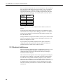
1
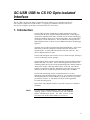
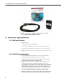
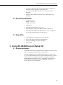
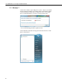
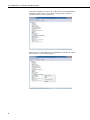
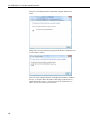
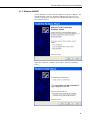
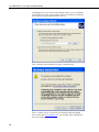
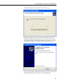
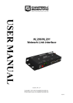
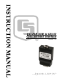
SC-USB USB to CS I/O
Opto-Isolated Interface
Revision: 1/12
C o p y r i g h t © 2 0 0 4 - 2 0 1 2
C a m p b e l l S c i e n t i f i c , I n c .
Warranty
“PRODUCTS MANUFACTURED BY CAMPBELL SCIENTIFIC, INC. are
warranted by Campbell Scientific, Inc. (“Campbell”) to be free from defects in
materials and workmanship under normal use and service for twelve (12)
months from date of shipment unless otherwise specified in the corresponding
Campbell pricelist or product manual. Products not manufactured, but that are
re-sold by Campbell, are warranted only to the limits extended by the original
manufacturer. Batteries, fine-wire thermocouples, desiccant, and other
consumables have no warranty. Campbell's obligation under this warranty is
limited to repairing or replacing (at Campbell's option) defective products,
which shall be the sole and exclusive remedy under this warranty. The
customer shall assume all costs of removing, reinstalling, and shipping
defective products to Campbell. Campbell will return such products by surface
carrier prepaid within the continental United States of America. To all other
locations, Campbell will return such products best way CIP (Port of Entry)
INCOTERM® 2010, prepaid. This warranty shall not apply to any products
which have been subjected to modification, misuse, neglect, improper service,
accidents of nature, or shipping damage. This warranty is in lieu of all other
warranties, expressed or implied. The warranty for installation services
performed by Campbell such as programming to customer specifications,
electrical connections to products manufactured by Campbell, and product
specific training, is part of Campbell’s product warranty. CAMPBELL
EXPRESSLY DISCLAIMS AND EXCLUDES ANY IMPLIED
WARRANTIES OF MERCHANTABILITY OR FITNESS FOR A
PARTICULAR PURPOSE. Campbell is not liable for any special, indirect,
incidental, and/or consequential damages.”
Assistance
Products may not be returned without prior authorization. The following
contact information is for US and international customers residing in countries
served by Campbell Scientific, Inc. directly. Affiliate companies handle
repairs for customers within their territories. Please visit
www.campbellsci.com to determine which Campbell Scientific company serves
your country.
To obtain a Returned Materials Authorization (RMA), contact CAMPBELL
SCIENTIFIC, INC., phone (435) 227-2342. After an applications engineer
determines the nature of the problem, an RMA number will be issued. Please
write this number clearly on the outside of the shipping container. Campbell
Scientific's shipping address is:
CAMPBELL SCIENTIFIC, INC.
RMA#_____
815 West 1800 North
Logan, Utah 84321-1784
For all returns, the customer must fill out a "Statement of Product Cleanliness
and Decontamination" form and comply with the requirements specified in it.
The form is available from our web site at www.campbellsci.com/repair. A
completed form must be either emailed to [email protected] or faxed to
(435) 227-9579. Campbell Scientific is unable to process any returns until we
receive this form. If the form is not received within three days of product
receipt or is incomplete, the product will be returned to the customer at the
customer's expense. Campbell Scientific reserves the right to refuse service on
products that were exposed to contaminants that may cause health or safety
concerns for our employees.
SC-USB Table of Contents
PDF viewers: These page numbers refer to the printed version of this document. Use the
PDF reader bookmarks tab for links to specific sections.
1. Introduction..................................................................1
2. Technical Specifications.............................................2
2.1
2.2
2.3
2.4
USB Specifications...................................................................................2
CS I/O Port Specifications........................................................................2
General Specifications ..............................................................................3
Ships With ................................................................................................3
3. Using SC-USB Driver and Setup CD ..........................3
3.1 Drivers Installation ...................................................................................3
3.1.1 Windows 7 ......................................................................................4
3.1.2 Windows Vista..............................................................................14
3.1.3 Windows 2000/XP........................................................................17
3.1.4 Windows 98/98SE/ME .................................................................20
3.1.5 Uninstalling the SC-USB Drivers .................................................22
3.1.6 Determining which COM Port the SC-USB has been Assigned ..22
3.2 Set-up Modes – the SC_USB Programming Utility ...............................24
3.2.1 Settings..........................................................................................24
3.2.1.1 Auto Detect (Automatic Baud Rate Detection)...................24
3.2.1.2 Selecting a Fixed Baud Rate ...............................................25
3.2.1.3 Enable All Comms Modes (Automatic Mode Detection) ...25
3.2.1.4 Enable CSDC Address 7 Mode ...........................................25
3.2.1.5 Enable CSDC Address 8 Mode ...........................................25
3.2.1.6 Enable SDC Comms Mode .................................................25
3.2.1.7 Enable ME Comms Mode ...................................................26
3.2.1.8 Set ID ..................................................................................26
3.2.2 Operating System (OS) Downloads..............................................26
4. Using the SC-USB with Campbell Software and
Hardware .................................................................26
4.1 LoggerNet EZSetup or Standard Setup ..................................................26
4.2 Using the Device Configuration (DevConfig) Utility ............................26
4.2.1 Accessing DevConfig ...................................................................26
4.2.2 Downloading a Datalogger OS .....................................................27
4.3 Use with the DSP4..................................................................................27
5. Troubleshooting ........................................................27
5.1 Installation ..............................................................................................27
5.2 Software Settings ....................................................................................27
5.3 Electronic Interference............................................................................28
i
SC-USB Table of Contents
Figure
1-1. Most of the components shipped with the SC-USB ............................... 2
ii
SC-USB USB to CS I/O Opto-isolated
Interface
The SC-USB is designed to allow Campbell Scientific dataloggers to communicate directly
with computers fitted with a USB interface. It provides an isolated connection which can
also operate at higher speeds than conventional RS-232 connections.
1. Introduction
The SC-USB is optically isolated thus preventing possible noise pickup
associated with PC power supplies and ground connections. It also supports
synchronous communications modes, available in some models of dataloggers,
which allow multiple devices to be connected in parallel. The SC-USB can be
used in place of an SC32B interface. The SC-USB also has the potential for
high-speed data transfer to the PC at up to 1 MBit/second where the datalogger
supports it.
Originally, the SC-USB was fitted with an integrated USB cable. At the end of
2009, the SC-USB was redesigned to include a connector instead of the
integrated cable. A 17648 USB cable attaches to the new connector. This
cable is shipped with the SC-USB.
The SC-USB will appear in PC software as a new virtual serial port, allowing it
to be used with many software packages.
The SC-USB PC drivers support various operating systems including Windows
98/ME, 2000, XP, Vista, and 7. The SC-USB is shipped with a software CD
containing suitable drivers and a set-up/programming utility called Sc-USB.exe
which can be found in a directory named ‘Utility’ on the CD. The CD also
contains a comprehensive help file, and manual. These files can be accessed
directly from the CD, if required, by double-clicking on the icon 'index'.
The SC-USB will normally operate ‘straight from the box’ for most
applications using the default settings. However, you can change the baud rate,
the communication rate, and its USB ID by using the Sc-usb.exe set-up utility
provided (see Section 3.2). This utility can also be used to upgrade the
SC-USB’s operating system.
Please check with Campbell Scientific if you wish to use the SC-USB with a
CR9000X.
NOTE
If you are using a CR5000 datalogger, make sure the datalogger
operating system is version 2.0 or later as this will enable the
highest communication speeds. For older versions set the
SC-USB to work in ME Comms Mode (see Section 3.2).
1
SC-USB USB to CS I/O Opto-isolated Interface
FIGURE 1-1. Most of the components shipped with the SC-USB.
SC12 cable and ResourceDVD not shown.
2. Technical Specifications
2.1 USB Specifications
•
USB Version 1.1
•
USB transfer rate up to 12 MBits/second
•
Active current consumption less than 85 mA (current drawn from PC)
•
Standby current consumption less than 18 mA (current drawn from PC)
•
17648 Cable Description: 6 ft (1.8 m) length; USB Type A male to Type B
male.
2.2 CS I/O Port Specifications
2
•
Opto-isolated from the PC/USB to 47 V AC or DC. Note that this is
signal isolation only, and does not provide safety isolation.
•
Supports asynchronous communication from 9600 to 115200 baud and
synchronous communication up to 1 MBit/second.
•
Campbell Scientific protocols implemented: supports Modem-Enable
(ME), Synchronous Device Communications protocol (SDC) and
Concurrent-SDC (CSDC) modes. Some of these modes may require that
the datalogger operating system be a specific version or higher. The SDC
mode only works with operating systems created since October 2002
(CR10X 1.18 or higher, CR23X 1.15 or higher, etc.) The CSDC mode
only works with a PakBus (PB) operating system and the CR5000.
•
Dataloggers supported 21X, CR7X, CR500, CR510, CR10, CR10X / TD /
PB, CR23X / TD / PB, CR800 series, CR1000, CR3000 and CR5000.
SC-USB USB to CS I/O Opto-isolated Interface
•
PC software compatibility PC200W, PC400, LoggerNet, RTDAQ and
most other packages that support virtual serial ports.
•
Active current consumption less than 19 mA (current drawn from
datalogger).
•
Quiscent current consumption less than 80 µA (current drawn from
datalogger).
2.3 General Specifications
•
Height: 0.8 in (2 cm)
Width: 1.6 in (4 cm)
Length: 3.0 in (7.5 cm)
•
Weight: 3.0 oz
•
Operating temperature range -25° to +50°C
•
EMC compliance: complies with EN61326:1998 (see Section 5.3)
•
Driver support for Windows 98 / ME / 2000 / XP / Vista / 7 supplied on
CD (Contact Campbell Scientific for other drivers)
•
17648 USB cable for connection to the PC’s USB port.
•
SC12 CS I/O cable for connection to the datalogger.
•
Driver CD containing setup utility and manual.
•
ResourceDVD.
2.4 Ships With
3. Using SC-USB Driver and Setup CD
3.1 Drivers Installation
The installation procedure is straightforward. The Windows set-up wizard will
guide you through the installation steps as indicated below.
This guide assumes that you are installing the drivers onto a ‘clean’ system
(i.e., one on which similar drivers have not been installed previously). If this is
not the case, then you should first uninstall the existing drivers using the
standard Windows procedure (see below). If upgrading your drivers from a
previous version of SC-USB driver, it is also important to deinstall the
previous drivers first to avoid conflicts.
3
SC-USB USB to CS I/O Opto-isolated Interface
3.1.1 Windows 7
Connect the SC-USB to a spare USB port on your PC. If there is an available
internet connection, Windows 7 will silently connect to the Windows Update
website and install any suitable driver it finds for the device. If no suitable
driver is found automatically, you will see a message similar to this...
...if so, use the following procedure to update the driver.
Click the Windows start button to bring up the start menu and click ‘Control
Panel’ as shown below...
4
SC-USB USB to CS I/O Opto-isolated Interface
Once the control panel appears, click ‘Hardware and Sound’...
Now click ‘Device Manager’...
5
SC-USB USB to CS I/O Opto-isolated Interface
In the Device Manager you will see ‘SC-USB USB TO CS I/O INTERFACE’
listed under ‘Other Devices’ with a yellow warning symbol to indicate a
problem as there is no driver installed yet.
Right click on ‘SC-USB USB TO CS I/O INTERFACE’ and click on ‘Update
Driver Software’ in the menu that appears...
6
SC-USB USB to CS I/O Opto-isolated Interface
You will now be given the choice to search automatically or browse for driver
software. Click the second option ‘Browse my computer for driver software’...
In the window that appears, browse for the location where the new drivers are
stored. This could be a CD drive or a folder on your computer, then click
‘Next’...
7
SC-USB USB to CS I/O Opto-isolated Interface
You will probably now be presented with the following window indicating that
the publisher can’t be verified, click ‘Install this driver software anyway’ to
continue...
The installation will then proceed and you will see the progress as follows...
8
SC-USB USB to CS I/O Opto-isolated Interface
Once this part of the installation is complete you will see the following
confirmation...
...click ‘Close’ to return to the Device Manager.
You will now see ‘SC-USB USB TO CS I/O ISOLATED INTERFACE’
displayed under Universal Serial Bus controllers (as shown below).
9
SC-USB USB to CS I/O Opto-isolated Interface
You will now notice a new device ‘USB Serial Port’ displayed under ‘Ports
(COM & LPT), again with a yellow warning symbol as now driver is yet
installed...
Right click on ‘USB Serial Port’ and click on ‘Update Driver Software’ in the
menu that appears...
10
SC-USB USB to CS I/O Opto-isolated Interface
You will now be given the choice to search automatically or browse for driver
software. Click the second option ‘Browse my computer for driver software’...
In the window that appears, browse for the location where the new drivers are
stored. This could be a CD drive or a folder on your computer, then click
‘Next’...
11
SC-USB USB to CS I/O Opto-isolated Interface
You will probably now be presented with the following window indicating that
the publisher can’t be verified, click ‘Install this driver software anyway’ to
continue...
The installation will then proceed and you will see the progress as follows...
12
SC-USB USB to CS I/O Opto-isolated Interface
Once this part of the installation is complete you will see the following
confirmation...
...click ‘Close’ to return to the Device Manager.
You will now see ‘SC-USB USB TO CS I/O ISOLATED INTERFACE
(COMx)’ displayed under Ports (COM & LPT), where x is the number of the
COM port assigned by Windows during the installation.
The installation is now complete. You can close the Device Manager and start
using your SC-USB interface.
13
SC-USB USB to CS I/O Opto-isolated Interface
3.1.2 Windows Vista
To install the drivers on a Vista PC you will need administrative rights or
access to the administrator password during the installation process. Make sure
you have the latest driver set (post-March 2008) which includes formal Vista
support. To start the installation, plug the SC-USB into a free USB port. The
found new hardware wizard will start and show this screen.
Select the first option as shown. You will normally get prompted to confirm
you want to continue (a Vista User Account Control Message). If you do not
have administrative rights to your machine, you will need to get an
administrator to authorize this step.
With Windows Vista the machine will always go and search all available
sources for the drivers (including the Internet) before asking for a local copy.
This leads to a long delay before the next step where you are prompted to
install a CD.
14
SC-USB USB to CS I/O Opto-isolated Interface
If you are installing from a CD insert it now. If the PC does not find the
drivers or if you are installing them from copy on your hard disk, select “Show
me other options” and choose the browse option to point to the directory
holding the drivers.
You will then get this message:
The drivers supplied are Microsoft WHQL certified by the SC-USB chipset
manufacturer (FTDI); however, changing the descriptor to SC-USB prevents
windows validating the drivers. Select the second option as it is safe to install
the drivers.
15
SC-USB USB to CS I/O Opto-isolated Interface
The process of installing the drivers should then complete and show this
screen.
Shortly after, a message will normally appear from the device installation icon
in your toolbar as follows:
Take note of the COM port that the SC-USB has been installed as, COM4 in
this case. You need to know this number when setting up the interface in
Campbell Scientific software. Click on close to the two options above to
finish. You are now ready to use the interface.
16
SC-USB USB to CS I/O Opto-isolated Interface
3.1.3 Windows 2000/XP
Use the USB cable to connect your SC-USB device to the PC’s USB port. The
first time that this is done, the ‘Found New Hardware Wizard’ screen will
normally be displayed, as shown below for XP (Windows 2000 screens may
not be identical to these).
Select ‘No, not this time’ and Press ‘Next’ and you will see the following
screen.
17
SC-USB USB to CS I/O Opto-isolated Interface
If installing from CD, you can select the automatic option; if you are installing
from another source, then you may need to select the second option and specify
the root directory which contains the driver files, e.g.
After selecting next the installation will pause with this message:
Select ‘Continue Anyway’ as the drivers are based upon Microsoft WHQL
drivers from FTDI (www.ftdichip.com). Only company names and identifiers
have been changed.
18
SC-USB USB to CS I/O Opto-isolated Interface
The Wizard will then continue through a number of steps, e.g.
Rather than completing it will appear to restart the installation again as the
‘Found New Hardware Wizard’ appears again. This is not an error. Windows
first installs the USB drivers and then the virtual serial port drivers. You need
to follow the same steps as above again, until finally you get to this screen.
If you subsequently change the device ID (see Section 3.2), the PC may request
the installation disk again as it will insist on re-installing the driver.
19
SC-USB USB to CS I/O Opto-isolated Interface
3.1.4 Windows 98/98SE/ME
Use the USB cable to connect your SC-USB device to the PC’s USB port. The
first time that this is done, the ‘Building Driver Information Database’ screen
followed by the ‘Add New Hardware Wizard’ screen will normally be
displayed, as shown below. (If it is not displayed immediately, try rebooting
the PC with the SC-USB plugged in or run the Add New Hardware option in
the Control Panel.)
Press ‘Next’ and you will see the following screen.
20
SC-USB USB to CS I/O Opto-isolated Interface
Select ‘Search for the best driver….’ and click ‘Next’. You will then see the
screen shown below.
Select the appropriate location; if using the supplied CD, the driver letter
should be your CD-ROM drive. For Windows 98 or ME you must specify the
subdirectory “win98me”, as above, otherwise the installer will try to install the
XP drivers from the default directory which will not work. Press ‘Next’ and, if
the drivers were successfully found, a confirmation screen will be displayed,
and the screen shown below will be displayed.
Press ‘Next’ and the drivers will be installed.
21
SC-USB USB to CS I/O Opto-isolated Interface
NOTE
In most cases the above process will be repeated as Windows
first installs the USB interface controller and then the virtual
serial port driver. Let Windows search for the serial driver in the
same directory as sthe USB driver.
The installation process will only need to be carried out once.
3.1.5 Uninstalling the SC-USB Drivers
To uninstall the drivers use the standard Windows procedure. Go to the
Windows ‘Control Panel’ and select ‘Add/Remove Programs’. Select
‘CAMPBELL SCIENTIFIC SC-USB Drivers’, click the ‘Add/Remove’ button
and follow the prompts.
3.1.6 Determining which COM Port the SC-USB has been Assigned
The above installation processes relies on parts of the Windows operating
system to assign a com port number to SC-USB. Often this will be the next
port number that is free. However, if other devices have been installed in the
past (some of which may no longer be plugged in), it may be assigned a higher
com port number.
To check which COM port it has got, you can simply monitor the appearance
of a new com port in the list of com ports offered in your software package
(e.g., LoggerNet) before and after the installation, or if there is any doubt, look
in the Windows Device Manager list under the ports section (access via the
control panel).
22
SC-USB USB to CS I/O Opto-isolated Interface
As shown below the com port number is shown at the end of the description.
In some cases a PC program may not offer the SC-USB COM port in its
selection list of available COM ports. Recent versions of Campbell Scientific
packages allow you to manually type the COM port into the selection window
to overcome this.
Older software may also limit you only up to COM4. In that case you would
need to free lower com port numbers (by deinstalling an unused COM port)
and move the assignment of the SC-USB. To do this right click on the
SC-USB in the device manager screen (as shown above) and select properties.
Then select Port Settings and then the Advanced button. In the next screen you
have the option to change the COM port number to another free number. ‘OK’
any change you make and close the Device Manager screen before reopening it
to confirm the change (it does not automatically refresh this change).
NOTE
The Baud rate settings in the driver/properties setting have no
influence on the operation of the SC-USB. The speed of
communication to the datalogger is normally determined
automatically by the SC-USB, although it can be set in other
ways. See the sections below.
23
SC-USB USB to CS I/O Opto-isolated Interface
3.2 Set-up Modes – the SC_USB Programming Utility
The Set-up button on the SC_USB.exe utility allows you to configure the
SC-USB interface to work with the supported dataloggers and peripherals and
their modes of operation. Before pressing the Set-up button, ensure that the
correct COM port is selected.
NOTE
This program is only needed for some older dataloggers or
datalogger operating systems.
The set-up screen is shown below, and the set-up modes are explained in detail.
3.2.1 Settings
3.2.1.1 Auto Detect (Automatic Baud Rate Detection)
Auto Detect will try to connect at the highest asynchronous baud rate the
datalogger can support. This can be used in most cases. The exceptions are:
•
Upgrading a datalogger operating system using CSOS.EXE, when the SCUSB must be set to 19200 baud.
•
Using Call Back, when you must fix the baud rate.
•
Using a 21X or CR7 datalogger, where the baud rate needs to be fixed and
set to either 9600 or 76800 baud (OS dependent).
•
Using a non-PakBus CR23X-TD datalogger – the baud rate may be
adjusted to the maximum supported by the datalogger. (By default it will
run at 9600 baud.) See Section 5.2 for more details.
Auto Detect is the Factory default.
24
SC-USB USB to CS I/O Opto-isolated Interface
3.2.1.2 Selecting a Fixed Baud Rate
Bit rate selections available are 9600, 19200, 38400, 57600, 76800 and 115200
baud as shown in the screenshot above. Select the highest rate supported by
the dataloggers being used.
3.2.1.3 Enable All Comms Modes (Automatic Mode Detection)
Selecting ‘Enable all Comms Modes’ automatically connects to the datalogger
using the communications method that uses the least physical hardware
resources. The priorities from highest to lowest are CSDC, SDC and finally
Modem Enable (ME) mode. The default mode can be used in most cases.
Exceptions are:
•
When other SDC or CSDC peripherals are being used, in which case a free
address must be selected.
•
When Call Back is being used it may be necessary to fix the
communication method to ME.
•
When using non-PakBus TD dataloggers, where the mode must be set to
ME.
•
When using a CR5000 datalogger with an operating system version earlier
than 2.0, where the mode must be set to ME.
Enable All Comms Modes is the Factory default.
3.2.1.4 Enable CSDC Address 7 Mode
Selecting ‘Enable CSDC Address 7 Mode’ will force the SC-USB to only
respond as the CSDC device with SDC address 7. This is useful when you
have another SDC-Concurrent device connected on the CSI I/O port. The
modem enable line (pin 5) is not used and is free for other use. CSDC mode
allows concurrent communication sessions. It is currently supported by
PakBus dataloggers and recent versions of the CR5000 operating system.
3.2.1.5 Enable CSDC Address 8 Mode
Selecting ‘Enable CSDC Address 8 Mode’ will force the SC-USB to only
respond as the CSDC device with SDC address 8. This is useful when you
have another CSDC device connected on the CS I/O port. The modem enable
line (pin 5) is not used and is free for other use. CSDC mode allows
concurrent communication sessions. It is currently supported by PakBus
dataloggers and recent versions of the CR5000 operating system.
3.2.1.6 Enable SDC Comms Mode
Selecting ‘Enable SDC Comms Mode’ will force the SC-USB to only respond
as an SDC communication device at address 9. In this mode asynchronous
communication is used at the chosen bit rate. The Modem Enable line (pin 5)
is not used and is free for other use. SDC mode allows the SC-USB to be
connected in parallel with modem devices. This mode is only supported in
CR510, CR10X and CR23X dataloggers with post-2002 standard (nonPakBus) operating systems.
25
SC-USB USB to CS I/O Opto-isolated Interface
3.2.1.7 Enable ME Comms Mode
Selecting ‘Enable ME Comms Mode’ will force the SC-USB to only respond
as a modem-enabled device. This would only be used when all other
connection modes are being used by other peripherals or for compatibility with
an older datalogger or operating system.
3.2.1.8 Set ID
Set ID is used to make the SC-USB interface unique. This is useful if you have
more than one SC-USB interface connected to the same PC at the same time.
The default ID as supplied is 00000001.
NOTE
Close the SC-USB utility when you have finished using it, as its
method of polling the SC-USB may cause the PC to become very
slow when running other programs.
3.2.2 Operating System (OS) Downloads
The OS download button in the Sc_USB.exe utility allows you to upgrade the
OS in the SC-USB to take advantage of new features and allow new product
support.
CAUTION
When using this option do not unplug the SC-USB or turn
off the computer, otherwise the operating system may be
corrupted and the SC-USB may then need to be returned
to the factory for repair.
4. Using the SC-USB with Campbell Software and
Hardware
4.1 LoggerNet EZSetup or Standard Setup
The SC-USB does not appear as any special device within Campbell Scientific
software packages. Instead, it appears as a new COM port to both Windows
and Campbell software. To use the SC–USB, if using the EZSetup Wizard,
you need to specify a “Direct Connect” and then select the new COM port
number assigned to the SC-USB (see Section 3.1.6 above). If using the setup
tool in LoggerNet, you need to Add a Root device, select the COM port option
and select the relevant com port number; then Add the datalogger or
Pakbusport directly to the new ComPort.
In general, the baud rate settings that are offered in the EZSetup or Setup
screens can be left at the default settings as they do not apply to the SC-USB
which determines the best speed to use by automatically negotiating this with
datalogger (see Section 3.2 for exceptions).
4.2 Using the Device Configuration (DevConfig) Utility
4.2.1 Accessing DevConfig
The SC-USB can be used with DevConfig to change datalogger settings. To
do this, open DevConfig and connect the datalogger to the PC’s USB port via
the SC-USB. Select the appropriate datalogger from the list. For the COM
26
SC-USB USB to CS I/O Opto-isolated Interface
port, select the new COM port number assigned to the SC-USB (see Section
3.1.6), and then press Connect.
4.2.2 Downloading a Datalogger OS
The SC-USB can be used to download operating systems to the CR510,
CR10X, and 23X dataloggers using this tool. The SC-USB must be set to a
fixed baud rate and this baud rate must match DevConfig. You cannot load
operating systems into the CR800, CR850, CR1000, or CR3000 dataloggers by
selecting the “Send OS” tab in DevConfig because these dataloggers only
support the low-level OS upload via the RS-232 port. However, you can load
an operating system into these dataloggers using the option to load a program
into the datalogger (under Logger Control) and changing the file type to
operating system. (You can load the OS with other Campbell Scientific
programs too using the program load options.) This technique does not reset as
many settings as the lower level “Send OS” option.
4.3 Use with the DSP4
It is possible to use the SC-USB to communicate with most dataloggers when
they are used with a DSP4 Heads-Up Display. As with other means of
communication, display of data on the DSP4 is suspended during
communication.
NOTE
For the CR5000 it is not possible to run any program that sends
data to the DSP4 and then communicate with the
SC-USB. This is because the CR5000 reserves the CS I/O port
solely for use by the DSP4. Contact Campbell Scientific for
further information.
5. Troubleshooting
5.1 Installation
If when installing the SC-USB the Hardware installation wizard is not
displayed immediately, try rebooting the PC with the SC-USB plugged in or
run the Add Hardware option in the Control Panel. If the wizard still does not
appear, it is possible that drivers are already installed for the SC-USB; check
using the Device Manager.
The SC-USB uses a chipset made by FTDI. Many other USB devices also use
this chipset. As a consequence, the SC-USB and other FTDI devices may
share some common driver files. To ensure that the latest files are used, install
the SC-USB after the other devices are installed. Also be aware that
re-installing an older device last may result in unreliability, as older drivers
may overwrite the newer ones without any warning.
5.2 Software Settings
Generally, no specific settings are required to use the SC-USB with Campbell
Scientific software. The datalogger should be entered in the device map as if it
were directly connected to the COM port assigned to the SC-USB. The baud
rate setting has no effect on the speed that the SC-USB communicates with the
datalogger. This is normally determined automatically. The 21X and CR7 and
non-PakBus TD dataloggers do not support automatic baud rate detection. In
27
SC-USB USB to CS I/O Opto-isolated Interface
these cases the SC-USB needs to be set to a fixed baud rate. This can either be
done using the SC-USB utility program (see Section 3.2) or if your software
package supports it; for example by using the ‘Generic modem’ option of
LoggerNet, the baud rate can be set by sending a single character code at the
start of each call to the datalogger. The codes are shown in the table below.
ASCII
Character
1
2
3
4
5
6
Baud Rate
9600
38400
57600
115200
76800
115200
The SC-USB can be left in auto mode; the numeric characters will not be
echoed.
If using the generic modem option of LoggerNet, you would enter a generic
modem between the COM port and the datalogger, and enter T"1" in the dial
script to force the baud rate to 9600 baud; the other hardware settings can be
left at their default values.
Setting the baud rate using the latter method is useful if you use the SC-USB to
move between a number of different types of dataloggers and wish to avoid
having to reconfigure it too often.
If you experience any problems using this software, please report this to
Campbell Scientific, giving full details with any solution if available, for
possible inclusion in a future release of this User Guide.
5.3 Electronic Interference
Electronic emissions emanating from the SC-USB interface itself are very low.
However, while verifying this during the development of the SC-USB,
Campbell Scientific became aware that many PCs have poor filtering of
emissions from their USB ports.
These emissions become apparent when a cable is plugged into the USB port,
as the cable acts as an antenna. If any such PC emissions (coming from the
SC-USB cable) cause problems with other equipment, you may be able to
reduce such noise by adding a clip-on ferrite choke to the SC-USB cable.
Position the choke on the cable close to the USB connector. The size of ferrite
is dependent on the level and frequency of noise emitted by the PC, and so
needs to be selected by trial and error. If in doubt, seek advice from the PC
manufacturer.
28
Campbell Scientific Companies
Campbell Scientific, Inc. (CSI)
815 West 1800 North
Logan, Utah 84321
UNITED STATES
www.campbellsci.com • [email protected]
Campbell Scientific Africa Pty. Ltd. (CSAf)
PO Box 2450
Somerset West 7129
SOUTH AFRICA
www.csafrica.co.za • [email protected]
Campbell Scientific Australia Pty. Ltd. (CSA)
PO Box 444
Thuringowa Central
QLD 4812 AUSTRALIA
www.campbellsci.com.au • [email protected]
Campbell Scientific do Brazil Ltda. (CSB)
Rua Luisa Crapsi Orsi, 15 Butantã
CEP: 005543-000 São Paulo SP BRAZIL
www.campbellsci.com.br • [email protected]
Campbell Scientific Canada Corp. (CSC)
11564 - 149th Street NW
Edmonton, Alberta T5M 1W7
CANADA
www.campbellsci.ca • [email protected]
Campbell Scientific Centro Caribe S.A. (CSCC)
300 N Cementerio, Edificio Breller
Santo Domingo, Heredia 40305
COSTA RICA
www.campbellsci.cc • [email protected]
Campbell Scientific Ltd. (CSL)
Campbell Park
80 Hathern Road
Shepshed, Loughborough LE12 9GX
UNITED KINGDOM
www.campbellsci.co.uk • [email protected]
Campbell Scientific Ltd. (France)
3 Avenue de la Division Leclerc
92160 ANTONY
FRANCE
www.campbellsci.fr • [email protected]
Campbell Scientific Spain, S. L.
Avda. Pompeu Fabra 7-9, local 1
08024 Barcelona
SPAIN
www.campbellsci.es • [email protected]
Please visit www.campbellsci.com to obtain contact information for your local US or International representative.