1
FATEC
Q172CPU(N)
Q173CPU(N)
MOTION CONTROLLER
SCHOOL TEXTBOOK
Microsoft® Windows® Personal Computer Operation Version
SW6RN-GSV22P
• SAFETY INSTRUCTIONS •
(Always read before starting practice)
When designing the system, always read the related manuals, and pay special attention to safety.
When practicing, pay attention to the following points and make sure to correctly handle the system.
[Precautions for Practice]
!
DANGER
• Do not touch the terminals while the power is ON. There is a risk of electric shock accidents.
• Always turn the power OFF or sufficiently confirm the surrounding safety before opening the safety
covers.
!
CAUTION
• Always follow the instructor's instructions when practicing.
• Do not remove the practice unit or change the wiring without instructions from the instructor.
Failure to observe this could lead to faults, incorrect operations, injuries or fires.
• Always turn the power OFF before installing or removing a unit.
There is a risk of unit faults or electric shocks if this is carried out while the power is ON.
• If any abnormal odor or noise is sensed during practice, always press the "Power switch" or "Emergency
Stop switch", and stop the machine.
• If any error occurs, notify your instructor immediately.
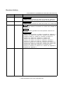
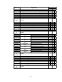
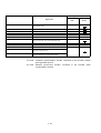
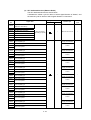
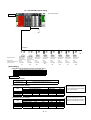
Revision History
* The textbook No. is indicated on the lower left of the back cover.
Date of print
January 2001
January 2001
*Textbook No.
SH-030010-A
SH-030010-B
Revision details
April 2001
SH-030010-C
Partial revision
Table of contents, section 9.2, section 9.9, section 10.1, section 10.8
March 2002
SH-030010-D
Additions
Section 3.2.5, section 2.3.6, section 3.2.7, section 3.2.8, Chapter 10,
Appendix 5
First print
Partial revision
Table of contents, section 2.2, section 3.2, section 9.3, section 9.5,
section 9.6, section 9.9, section 9.10, section 10.4, section 10.10
Revision
Changed teaching operation to monitor operation, section 9.10.2
Partial revision
Table of contents, section 1.1, section 1.3, section 2.1, section 2.1.1,
section 2.1.2, section 2.2, section 2.2.1, section 2.2.2, section 2.3,
Chapter 3, section 3.1, section 3.1.2, section 3.2, section 4.1,
section 4.2.1, section 4.2.4, section 4.3.1, section 4.3.2,
section 4.3.3, section 4.3.4, section 4.3.5, section 4.4.1,
section 4.4.2, section 7.2, section 7.4, section 8.1, section 8.2,
section 8.3.1, section 8.4, section 9.1, section 9.2, section 9.3,
section 9.5, section 9.6.1, section 9.6.2, section 9.6.3, section 9.6.4,
section 9.6.5, section 9.7, section 9.9.1, section 9.9.2, section 9.9.3,
section 9.9.4, section 9.9.5, section 9.10.1, section 9.10.3,
section 11.3, section 11.4, section 11.4.1, section 11.8, Appendix 2,
Appendix 3.2, Appendix 4
2002 MITSUBISHI ELECTRIC CORPORATION
CONTENTS
Chapter 1 Outline
1-1 to 1-6
1.1 Features of the motion controller............................................................................................................ 1-1
1.2 Outline of control .................................................................................................................................... 1-4
1.2.1 Real mode control for SV13 transfer assembly and SV22 automatic machine .............................. 1-4
1.2.2 Virtual mode control for SV22 automatic machine .......................................................................... 1-5
1.3 Items required to start up system ........................................................................................................... 1-6
Chapter 2 Explanation of Functions
2-1 to 2-8
2.1 List of specifications ............................................................................................................................... 2-1
2.1.1 List of motion controller specifications............................................................................................. 2-1
2.1.2 List of SFC performance specifications ........................................................................................... 2-2
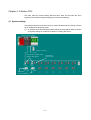
2.2 System configuration drawing ................................................................................................................ 2-3
2.2.1 Q172CPU(N) system....................................................................................................................... 2-3
2.2.2 Q173CPU(N) system....................................................................................................................... 2-4
2.3 Names of each part ................................................................................................................................ 2-5
Chapter 3 Q-PLC Multi-CPU
3-1 to 3-14
3.1 Multi-CPU system................................................................................................................................... 3-2
3.1.1 Setting the multi-CPU system.......................................................................................................... 3-2
3.1.2 Mounting position of Q-PLC CPU/Q motion CPU ........................................................................... 3-3
3.1.3 Input/output numbers....................................................................................................................... 3-4
3.1.4 Automatic refresh for shared memory ............................................................................................ 3-5
3.2 Multi-CPU motion dedicated commands................................................................................................ 3-7
3.2.1 SFCS motion SFC program start command ................................................................................... 3-7
3.2.2 GINT interrupt command to other machine’s CPU.......................................................................... 3-9
3.2.3 Read from DDRD Q motion CPU device command ..................................................................... 3-11
3.2.4 Write to DDWR Q motion CPU device command ......................................................................... 3-13
Chapter 4 Q Motion CPU
4-1 to 4-30
4.1 System settings ...................................................................................................................................... 4-1
4.2 Servo data .............................................................................................................................................. 4-2
4.2.1 Basic system setting ........................................................................................................................ 4-3
4.2.2 Multi-CPU setting ............................................................................................................................. 4-4
4.2.3 Fixed parameters............................................................................................................................. 4-5
4.2.4 Servo parameters ............................................................................................................................ 4-6
4.2.5 Zero point return data .................................................................................................................... 4-10
4.2.6 JOG operation data ....................................................................................................................... 4-11
4.2.7 Parameter block............................................................................................................................. 4-12
4.2.8 Limit switch output function............................................................................................................ 4-13
4.3 Positioning control device..................................................................................................................... 4-14
4.3.1 Status/command signals M2400 to M5471 (For Q172) ................................................................ 4-15
4.3.2 Internal relays M2000 to M2319 (For Q172) ................................................................................. 4-18
-1-
4.3.3 Data registers D0 to D1315 (For Q172) ........................................................................................ 4-20
4.3.4 Special relays M9073 to M9079, M9104, M9105.......................................................................... 4-24
4.3.5 Special registers D752 to D799, D9017, D9019, D9104, D9180 to D9199 (For Q172) ............... 4-24
4.4 Motion SFC dedicated devices............................................................................................................. 4-26
4.4.1 Motion registers (#0 to #8191)....................................................................................................... 4-26
4.4.2 Coast timer (FT)............................................................................................................................. 4-29
Chapter 5 SFC Program
5-1 to 5-20
5.1 SFC program configuration .................................................................................................................... 5-1
5.2 List of SFC symbols................................................................................................................................ 5-2
5.3 List of branch/connection diagrams........................................................................................................ 5-4
5.4 SFC program name................................................................................................................................ 5-5
5.5 Steps....................................................................................................................................................... 5-6
5.5.1 Motion control step .......................................................................................................................... 5-6
5.5.2 Operation control step ..................................................................................................................... 5-7
5.5.3 Subroutine call/start step ................................................................................................................. 5-8
5.5.4 Clear step......................................................................................................................................... 5-9
5.6 Transition .............................................................................................................................................. 5-10
5.7 Jump/pointer......................................................................................................................................... 5-11
5.8 END ...................................................................................................................................................... 5-11
5.9 Branch/connection................................................................................................................................ 5-12
5.9.1 Parallel shifting............................................................................................................................... 5-12
5.9.2 Selective branch/connection.......................................................................................................... 5-13
5.9.3 Parallel branch/parallel connection................................................................................................ 5-14
5.10 Y/N transition ...................................................................................................................................... 5-15
5.11 Task operation.................................................................................................................................... 5-17
5.12 SFC parameters ................................................................................................................................. 5-19
5.12.1 Task parameters.......................................................................................................................... 5-19
5.12.2 Program parameters.................................................................................................................... 5-19
5.13 SFC program start method................................................................................................................. 5-20
5.14 SFC program end method.................................................................................................................. 5-20
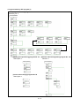
Chapter 6 SV22 Servo Programs
6-1 to 6-24
6.1 Servo program........................................................................................................................................ 6-1
6.1.1 Servo program configuration ........................................................................................................... 6-1
6.1.2 List of servo commands................................................................................................................... 6-2
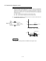
6.1.3 Linear control ................................................................................................................................... 6-8
6.1.4 Circular interpolation control using auxiliary point designation ....................................................... 6-9
6.1.5 Circular interpolation control using radius designation.................................................................. 6-10
6.1.6 Circular interpolation control using center point designation......................................................... 6-11
6.1.7 Fixed-dimension feed control ........................................................................................................ 6-12
6.1.8 Speed control................................................................................................................................. 6-12
6.1.9 Speed/position changeover control ............................................................................................... 6-13
6.1.10 Speed changeover control........................................................................................................... 6-14
6.1.11 Constant-speed control................................................................................................................ 6-15
6.1.12 Repeated control (for speed changeover control and uniform speed control)............................ 6-16
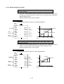
6.1.13 Simultaneous start ....................................................................................................................... 6-17
-2-
6.1.14
6.1.15
6.1.16
6.1.17
6.1.18
6.1.19
6.1.20
Zero point return .......................................................................................................................... 6-18
Position follow-up control............................................................................................................. 6-19
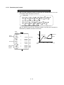
High-speed oscillation control...................................................................................................... 6-20
Helical interpolation control with auxiliary point designated ........................................................ 6-21
Helical interpolation control with radius designated .................................................................... 6-22
Helical interpolation control with center point designated ........................................................... 6-23
Current value change .................................................................................................................. 6-24
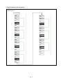
Chapter 7 Operation Control Program
7.1
7.2
7.3
7.4
7-1 to 7-10
Order of operator and function priority ................................................................................................... 7-1
List of operation control and transition commands ................................................................................ 7-2
Dedicated motion function (CHGV, CHGT) ........................................................................................... 7-4
Other commands .................................................................................................................................... 7-6
Chapter 8 Windows Personal Computer Operations
8-1 to 8-16
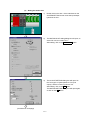
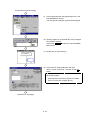
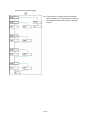
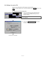
8.1 Flow of creating data for operating motion controller............................................................................. 8-1
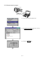
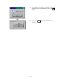
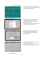
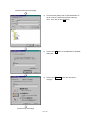
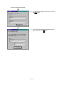
8.2 Registering the main unit OS ................................................................................................................. 8-2
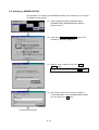
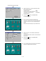
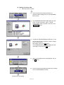
8.3 Setting the Q-PLC CPU.......................................................................................................................... 8-7
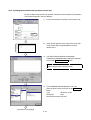
8.3.1 Reading the sequence program ...................................................................................................... 8-7
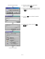
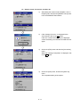
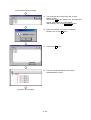
8.3.2 Setting the multi-CPU ...................................................................................................................... 8-8
8.3.3 Writing the sequence program ...................................................................................................... 8-11
8.4 Starting up SW6RN-GSV22P............................................................................................................... 8-13
Chapter 9 Basic Practice Using the SV22 Real Mode
9-1 to 9-68
9.1 Details of practice ................................................................................................................................... 9-1
9.2 Q172CPU practice machine system configuration ................................................................................ 9-2
9.3 System setting ........................................................................................................................................ 9-5
9.4 Setting the servo data........................................................................................................................... 9-12
9.5 Practice SFC programs ........................................................................................................................ 9-15
9.6 Creating SFC programs ....................................................................................................................... 9-19
9.6.1 Creating a new SFC program........................................................................................................ 9-19
9.6.2 Creating the SFC diagram............................................................................................................. 9-21
9.6.3 Inputting the transition and operation control step ........................................................................ 9-27
9.6.4 Inputting the motion control step ................................................................................................... 9-31
9.6.5 SFC program parameter setting and batch conversion ................................................................ 9-36
9.7 Writing to the motion CPU.................................................................................................................... 9-38
9.8 Test operation....................................................................................................................................... 9-40
9.8.1 JOG operation ............................................................................................................................... 9-40
9.8.2 Running the servo program ........................................................................................................... 9-42
9.9 Program for operation........................................................................................................................... 9-44
9.9.1 Initialization .................................................................................................................................... 9-44
9.9.2 JOG operation ............................................................................................................................... 9-46
9.9.3 Main routine SFC program (real mode operation) ........................................................................ 9-49
9.9.4 Zero point return ............................................................................................................................ 9-50
9.9.5 Continuous positioning .................................................................................................................. 9-51
9.10 Operating the practice machine ......................................................................................................... 9-53
9.10.1 Operation ..................................................................................................................................... 9-53
-3-
9.10.2 Monitor operation......................................................................................................................... 9-56
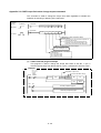
9.10.3 Monitor trace graph...................................................................................................................... 9-59
9.11 Ending the operations ........................................................................................................................ 9-68
9.11.1 Ending the SW6RN-GSV22P operations .................................................................................... 9-68
9.11.2 GX Developer END operation ..................................................................................................... 9-68
Chapter 10 Applied Practice with SV22 Real Mode
10-1 to 10-46
10.1 Details of practice ............................................................................................................................... 10-1
10.2 Q172CPU practice machine system configuration ............................................................................ 10-2
10.3 Practice SFC programs ...................................................................................................................... 10-5
10.4 Writing to the motion CPU................................................................................................................ 10-11
10.5 Program for operation ...................................................................................................................... 10-16
10.5.1 JOG operation ........................................................................................................................... 10-16
10.5.2 Main routine SFC program (real mode operation) .................................................................... 10-19
10.5.3 Execution of servo program (motion control step)..................................................................... 10-20
10.5.4 Stopping..................................................................................................................................... 10-24
10.5.5 Error reset .................................................................................................................................. 10-25
10.5.6 Current value change ................................................................................................................ 10-27
10.5.7 Speed change (CHGV).............................................................................................................. 10-28
10.5.8 Reading actual current value..................................................................................................... 10-30
10.5.9 Continuous positioning .............................................................................................................. 10-32
10.5.10 M code function ....................................................................................................................... 10-34
10.5.11 Indirect setting of servo program address ............................................................................... 10-36
10.6 Operating the practice machine ....................................................................................................... 10-38
10.6.1 Operation ................................................................................................................................... 10-38
Chapter 11 Practicing with the SV22 Virtual Mode
11-1 to 11-44
11.1 Mechanism program........................................................................................................................... 11-1
11.1.1 Mechanism module connection diagram..................................................................................... 11-1
11.1.2 List of mechanism modules ......................................................................................................... 11-2
11.1.3 Virtual servomotor........................................................................................................................ 11-3
11.1.4 Synchronous encoder.................................................................................................................. 11-3
11.1.5 Virtual axis ................................................................................................................................... 11-3
11.1.6 Gears ........................................................................................................................................... 11-3
11.1.7 Clutch........................................................................................................................................... 11-4
11.1.8 Transmission ............................................................................................................................... 11-5
11.1.9 Differential gears.......................................................................................................................... 11-5
11.1.10 Rollers........................................................................................................................................ 11-5
11.1.11 Ball screw................................................................................................................................... 11-6
11.1.12 Rotary table................................................................................................................................ 11-6
11.1.13 Cam ........................................................................................................................................... 11-7
11.2 Details of practice ............................................................................................................................... 11-9
11.3 Starting up SW3RN-CAMP and creating the cam ........................................................................... 11-11
11.4 SFC program for virtual mode .......................................................................................................... 11-16
11.4.1 New creation of SFC program for virtual mode......................................................................... 11-18
11.4.2 Inputting the motion control steps for the virtual mode.............................................................. 11-22
11.5 Editing the mechanism ..................................................................................................................... 11-26
-4-
11.6 Writing to the motion CPU................................................................................................................ 11-30
11.7 Reading of sequence program from Q-PLC CPU............................................................................ 11-31
11.8 SFC program for practice ................................................................................................................. 11-33
11.9 Practice machine operations ............................................................................................................ 11-39
11.10 Exercise (Roller setting) ................................................................................................................. 11-44
Appendix
A-1 to A-40
Appendix 1 Examples of programs for SV22 virtual mode ..........................................................................A-1
Appendix 2 Sample motion SFC ................................................................................................................A-10
Appendix 3 Operating the Windows personal computer............................................................................A-21
Appendix 3.1 Backing up an FD .............................................................................................................A-21
Appendix 3.2 Installing SW6RN-GSV22P ..............................................................................................A-23
Appendix 4 Comparison between A173UHCPU/A172SHCPUN...............................................................A-28
Appendix 5 Sequence command dedicated to motion ..............................................................................A-30
Appendix 5.1 SVST servo program start request command..................................................................A-30
Appendix 5.2 CHGA current value change command ...........................................................................A-32
Appendix 5.3 CHGV speed change command ......................................................................................A-34
Appendix 5.4 CHGT torque limit value change request command ........................................................A-36
Appendix 6 Explanation of terms................................................................................................................A-38
-5-
Introduction
This is the school textbook prepared to provide an understanding of the motion controller to enable easy
control of the multi-axis positioning operations.
In this textbook, the outline of the Q motion controller is explained, and the methods of setting the data to
carry out positioning using a DOS/V personal computer and the SW6RN-GSV22P automatic machine
software package are explained. In addition, the methods of creating servo programs, mechanical support
language and sequence programs are explained.
(The software package and function specifications will differ according to the machine model.)
-6-
Chapter 1 Outline
1.1 Features of the motion controller
The motion controller has the following features.
(1) Q-PLC CPU and multi-CPU system
A flexible system configuration, which allows the processing load to be spread
out, is realized by carrying out complicated servo control with the Q motion CPU
unit, and other machine control and information with the Q-PLC CPU unit.
(2) Product line-up to match applications
The following motion controller models are available to match the system scale
required for multi-axis positioning.
• Q172CPU(N) (1 to 8 axes multi-axis positioning function)
• Q173CPU(N) (1 to 32 axes multi-axis positioning function)
(3) Control using MR-H-B(N)/MR-J2(S)-B type servo amplifier possible
A 10W to 55kW servomotor can be controlled by connecting the MR-H-B(N)/MRJ2(S)-B/MR-J2M-B type servo amplifier externally to the motion network
SSCNET.
(The Q172 can control up to eight servomotors and the Q173 up to 32
servomotors.)
(4) High-speed serial communication with servo amplifier possible
Using the motion network SSCNET high-speed serial communication, the servo
data can be collected, the servo parameter can be changed, the servo can be
tested and monitored, and the mechanism program can be monitored. The speed
command can be output at up to 10Mpps, enabling high-speed high-accuracy
positioning.
(5) Absolute position system possible
An absolute position system can be structured by using a servomotor with
absolute position detector. (Zero point return is not required even if a power
failure occurs.)
(6) Windows personal computer can be used as positioning programming tool
By using a Windows personal computer with the dedicated software package, the
motion SFC can be programmed, the servo control can be programmed, monitored
and tested.
Windows personal computer .............................................SW6RNC-GSVPRO
1-1
(7) Operating system (OS) can be changed
Software packages to match applications are available, and by directly writing the
optical OS (refer to comparison table in section 2.1) into the CPU's built-in flash
memory, a motion controller matching each machine can be created.
This system is also compatible with software package function upgrades.
1) SV13 for transfer assembly
Using the dedicated servo commands, 1 to 4-axis linear interpolation, 2-axis
circular interpolation, 3-axis helical interpolation, CP control (uniform speed
control), speed control and position follow-up control can be carried out,
making this system suitable for applications such as transfer machines and
assembly machines.
Order control is enabled with SFC.
2) SV22 for automatic machine
Multiple servomotors can be simultaneously controlled with the mechanical
support language, and cam control can be carried out with the software. This
is suitable for applications such as automatic machines.
(8) Software cam ... Valid only with SV22
When the cam mechanism, often used in machine mechanisms is replaced with a
virtual mode cam for servomotor control, the following features can be realized.
1) Cam curve data can be created easily with the cam curve creation software
package, thereby eliminating the need to manufacture cam parts.
2) The cam can be replaced easily by changing the cam No. in the motion SFC
program.
3) There is no need to consider wear and life unique to the cam.
(9) Mechanism support language (Mechanism program) ... Valid only with SV22
Conventionally, synchronous operation and coordinated operation were required
for industrial machines and automatic machines, and as a means to achieve this,
each operation was mechanically connected.
With this method, the output mechanisms such as the rotation operation, linear
operation, reciprocating operation and feed operation, are operated from the main
shaft, which is the drive source, using a conveyance mechanism such as gears, a
clutch or crank. Although accurate synchronization operation and coordinate
operations are possible, this method lacks flexibility.
The mechanical support language frees the system from the conventional
mechanical connection, and allows the positioning control functions and
performance to be improved because the servomotor is controlled by processing
the machine mechanism movements with software. At the same time, this is an
electrical method, so there are few limitations to the mechanism and rational
designs can be made.
The system from the main shaft to the conveyance mechanism such as the gears,
clutch, reduction gears or differential gears, to the output mechanism such as the
roller output, ball screw output, rotary table output or cam output are described
with figures on the peripheral device screen. Just by setting each module
parameter, the synchronized operation and coordinate operation can be realized
and a flexible control system can be easily structured.
Thus, machine parts such as the main shaft, gears, clutch, crank, reduction gears,
differential gears and cam can be greatly reduced or omitted, allowing costs to be
reduced and wear to be eliminated.
1-2
(10) Teaching function
A servo program to match the actual part can be created with the current value
teaching function.
(11) Limit switch function
The ON/OFF signal corresponding to the watch data range, set for each output
device (X, Y, M, L, B) is output.
Output devices for up to 32 points can be set.
1-3
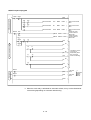
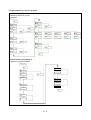
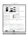
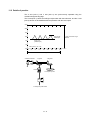
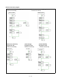
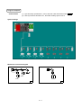
1.2 Outline of control
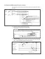
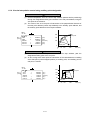
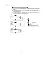
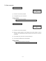
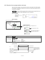
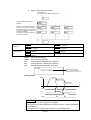
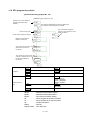
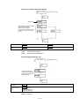
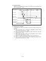
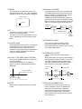
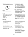
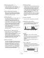
1.2.1 Real mode control for SV13 transfer assembly and SV22 automatic machine
(a) A system containing a servomotor is directly controlled with the servo program.
(b) The positioning parameters must be set, and the servo program and positioning
sequence program must be created.
(c)
The procedures for positioning control are indicated below.
1) Start up of the motion SFC program is requested with the sequence
program's SFCS command
2) Positioning control is carried out with the designated motion SFC program
3)
The servomotor is controlled
Q-PLC CPU
Q motion CPU
Sequence program
Motion SFC program
1)
SP.SFCS ......... K0 .........
Motion SFC
program start
request
command
Transfer
Servo amplifier
[G100]
M2049//Accept servo ON?
Servo program
Start program No. designation
* The motion SFC program can also be started
automatically with parameter settings.
2)
3)
[K10: Real
1 INC-2
Axis
1,
Axis
2,
Composite speed
10000 PLS
20000 PLS
30000 PLS/sec
END
Parameters for positioning
SYSTEM SETTING
FIXED PARA
SERVO PARA
P.B. DATA
ZERO P. DATA
JOG DATA
LMT. SW. DATA
1-4
Servomotor
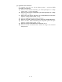
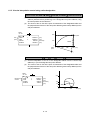
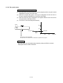
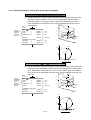
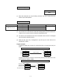
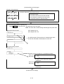
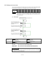
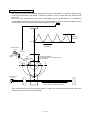
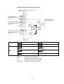
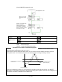
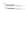
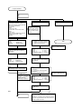
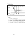
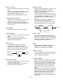
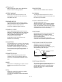
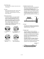
1.2.2 Virtual mode control for SV22 automatic machine
(a) The virtual mode processes synchronous control with the software using a
mechanism program structured with a virtual main shaft and mechanism
module. By using the virtual mode, the synchronous control conventionally
carried out with a mechanism such as the main shaft, gears and cam, can be
used for positioning control using a servomotor.
(b) With the virtual mode, in addition to the positioning parameters, servo
program and motion SFC program used in the real mode, a mechanism
program must be prepared.
(c) The procedures for carrying out positioning control in the virtual mode are
indicated below.
1) Start of the SFC program for the virtual mode is requested with the
SFCS command in the sequence program.
2) Start mechanism program's virtual servomotor
3)
4)
Via the conveyance model, the operation results are output to the servo
amplifier set in the output module
The servomotor is controlled
Q-PLC CPU
Q motion CPU
Sequence program
SP.SFC • • • • K0 • • • •
Motion SFC program
1)
Mechanism program
Drive module
(Vritual servomotor)
Transfer
Conveyance module
Motion SFC
Program start
Start program No. designation
* The motion SFC program can also be started
automatically with parameter settings.
[G200]
M2044//In virtual mode?
[K100: Vertual]
1 VF
Axis 1
Composite speed
2)
(Axis 1)
D 0 PLS/sec
END
Output
module
Parameters for oisitioning
SYSTEM SETTING
FIXED PARA
SERVO APRA
P.B. DATA
3)
LMT. SW. DATA
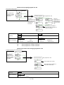
• As zero point return cannot be carried out in the virtual mode, the zero
point return data is not used. (Zero point return is carried out in the real
mode.)
4)
• JOG operation in the virtual mode is controlled by the JOG operation
data set in the drive module parameters.
• The external synchronous encoder pulses can be input to a
[synchronous encoder input unit or manual pulse generator input unit]
to operate the mechanism program's synchronous encoder.
1-5
Servo amplifier
Servo amplifier
Servomotor
Servomotor
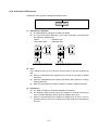
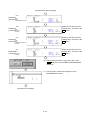
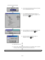
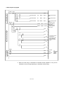
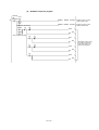
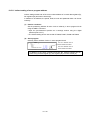
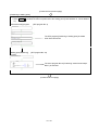
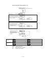
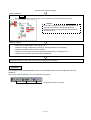
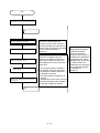
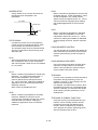
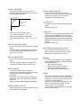
1.3 Items required to start up system
Always carry out the steps enclosed in the solid-line box.
Carry out the steps enclosed in the dotted box as necessary.
1
Motion controller device selection,
system assembly, wiring
Select the devices such as the Q-PLC base, power supply unit, Q motion
CPU, Q-PLC CPU, motion unit, servo amplifier, servomotor and cables.
Assemble and wire the system.
2
Installation of software package into
Windows personal computer
Install the software package (SNETP, GSV13P, GSV22P, CAMP, GX
Developer, etc.).
3
Setting of Q-PLC CPU multi-CPU
Create with GX Developer.
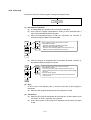
4
Sequence program creation
Create with GX Developer.
5
Writing of data to Q-PLC CPU
Using PC write operations, write the sequence programs and PC parameters.
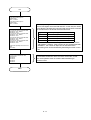
6
CAMP startup and cam creation
Create the cam when using it for the output module with SV22.
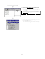
7
SV13, SV22 start up (Project control)
Start up the software package to be used, and carry out project control.
8
Creation of system settings
Create the system basic settings, multi-CPU settings, Q-PLC base, motion
unit, servo amplifier, servomotor and axis No., etc., as the motion controller
system.
9
Servo data creation
• Fixed parameters
• Servo parameters
• Zero point return data
• JOG operation data
• Parameter block
10
Servo data creation
• Limit switch data
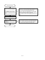
11
Creation of motion SFC program
12
Mechanism program creation
Create this when using SV22.
13
Connection of cable to Q motion CPU
The Windows personal computer uses the SSCI/F card (A30CD-PCF) or
SSCI/F board (A30BD-PCF/A10BD-PCF). (Cable Q170CDCBL3M/
Q170BDCBL3M)
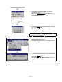
14
SSCNET communication task start
Start up SW6RN-SNETP.
15
Installation of OS into Q motion CPU
Install using the installation operations on the Servo Menu screen. (Carry out
only once when structuring the system.)
16
Writing of data to Q motion CPU
Write the motion SFC program, servo data, servo program, mechanism
program and cam data.
17
Resetting of Q-PLC CPU
Press the RESET switch on the Q-PLC CPU.
18
Running of Q-PLC CPU and Q motion
CPU
Press the RUN switch on the Q-PLC CPU and Q motion CPU.
•
•
•
•
•
Set the unit setting, movement amount per pulse, and stroke limit value, etc.
Set the rotation direction and automatic tuning, etc.
Set the zero point return direction, method, address and speed, etc.
Set the JOG speed limit value and parameter block No., etc.
Set the speed limit value, acceleration/deceleration time and torque limit
value, etc.
Set this only when using the limit switch output function.
1-6
Chapter 2 Explanation of Functions
The system functions are explained in this chapter.
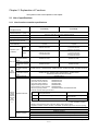
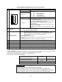
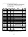
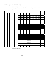
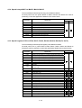
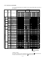
2.1 List of specifications
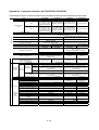
2.1.1 List of motion controller specifications
Model
Q172CPU(N)
Q173CPU(N)
Comparison item
Outline dimensions
122.4 (H) × 27.4 (W) × 89.3 (D): Q172/Q173CPU
104.4 (H) × 27.4 (W) × 114.3 (D): Q172/Q173CPUN
[mm]
Number of control axes
8 axes
32 axes
Manual pulse generator
3 units
INC synchronous encoder/
ABS synchronous encoder
8 units
12 units
Tracking enable input
(clutch ON/OFF)
8 points
12 points
SV13
0.88ms/1 to 8 axes
0.88ms/1 to 8 axes
1.77ms/9 to 16 axes
3.55ms/17 to 32 axes
SV22
0.88ms/1 to 4 axes
1.77ms/5 to 8 axes
0.88ms/1 to 4 axes
1.77ms/5 to 12 axes
3.55ms/13 to 24 axes
7.11ms/25 to 32 axes
Motion SFC compatible
for transfer assembly
(SV13)
SW6RN-SV13QD
SW6RN-SV13QB
Motion SFC compatible
for automatic machine
(SV22)
SW6RN-SV22QC
SW6RN-SV22QA
Operation cycle
(at default)
Main OS
Motion SFC compatible
for transfer assembly
(SV13)
SW6RN-GSV13P, SW6RN-SNETP, SW6RN-DOSCP, SW3RN-DOCPRNP, SW20RN-DOCPRNP
Peripheral Motion SFC compatible
software for automatic machine
(SV22)
SW6RN-GSV22P, SW3RN-CAMP, SW6RN-SNETP, SW6RN-DOSCP,
SW3RN-DOCPRNP, SW20RN-DOCPRNP
Digital oscilloscope
SW6RN-DOSCP
SW6RNC-GSV (General startup support software (CD-ROM) × 1 disk)
• Transfer assembly software:
SW6RN-GSV13P
• Automatic machine software:
SW6RN-GSV22P
• Cam data creation software:
SW3RN-CAMP
• Digital oscilloscope software:
SW6RN-DOSCP
• Communication system software: SW6RN-SNETP
• Document printing software:
SW3RN-DOCPRNP, SW20RN-DOCPRNP
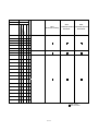
Personal computer working environment
General
startup
SW6RNC-GSVPRO
support
software
package
MT
Developer
OS
Japanese Windows NT4.0 (Service Pack2 and
above)/Windows98
Japanese Windows2000
CPU
Pentium 133MHz or higher recommended
Pentium II 233MHz or higher
recommended
Memory
32MB or more recommended
64MB or more recommended
• Required hard disk capacity: SW6RNC-GSV ... 51MB + SW6RNC-GSVHELP ... 108MB
(custom installation possible)
• Display: SVGA (resolution: 800 × 600 dots, display colors: 256) or higher
• Application software: Word97, Excel97 or Word2000, Excel2000 (required for document printing)
SW6RNC-GSVHELP (Operation Manual (CD-ROM) × 1 disk)
Installation Manual
SW6RNC-GSVPRO
SW6RNC-GSVSET
A30CD-PCF (SSC I/F card (PCMIA TYPE II 1CH card))
Q170CDCBL3M (A30CD-PCF cable 3m)
PLC software package
GX Developer: SWoD5C-GPPW *1
*1: Use version 6 or higher for o.
2-1
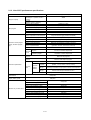
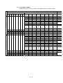
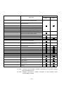
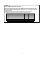
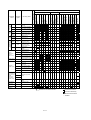
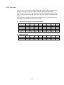
2.1.2 List of SFC performance specifications
Item
Program capacity
SFC program
Q173CPU(N)/Q172CPU(N)
Code total
(SFC diagram + operation control +
transition)
287kB
Text total
(operation control + transition)
224kB
Number of SFC programs
256 (No.0 to 255)
SFC diagram size/program
Maximum 64kB (including SFC diagram comments)
Number of SFC steps/program
Maximum 4094 steps
Selective branches/branch
255
Parallel branches/branch
255
Parallel branching nest
Maximum 4 levels
Number of operation control programs
Total 4096 including F (one execution type)/
FS (scan execution type) (F/FS0 to F/FS4095)
Number of transition programs
4096 (G0 to G4095)
Code size/program
Maximum approx. 64kB (32766 steps)
Number of blocks (lines)/program
Operation control program
(F/FS), transition program
(G)
Maximum 8192 blocks (for 4 steps (minimum)/block)
Number of characters/block
Maximum 128 characters (including comments)
Number of operators/block
Maximum 64 operators
(operators: constant, word device, bit device)
( ) nests/block
Maximum 32 levels
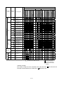
Operation control
Description program
method
Transition program
Formula, bit condition expressions
Formula, bit condition expression,
comparison condition expressions
Number of simultaneous execution
programs
Maximum 256 programs
Number of simultaneous active
programs
Maximum 256 steps/all programs
Normal task
Execution specifications
Execute at motion main cycle
Set period
Execution
tasks
Event task
(masking
possible)
Execute at each set period
(0.88ms, 1.77ms, 3.55ms, 7.11ms, 14.2ms)
External
interrupt
Of interrupt unit QI60's 16 input points, execute at set input ON
PLC
interrupt
Execute with interrupt command from PLC
NMI task
Of interrupt unit QI60's 16 input points, execute at set input ON
Input/output (X/Y)
specifications
8192 points
Number of actual input/
output (PX/PY) points
256 points
Number of internal relay (M) points
8192 points
Number of latch relay (L) points
Devices only in motion CPU
Number of link relay (B) points
8192 points
Number of annunciator (F) points
2048 points
Number of special relay (M) points
256 points
Number of data register (D) points
8192 points
Number of link register (W) points
8192 points
Number of special register (D) points
256 points
Number of motion device (#) points
8192 points
Number of free run timer (FT) points
1 point (888µs)
2-2
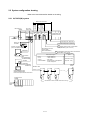
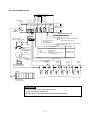
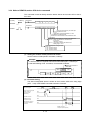
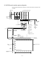
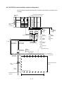
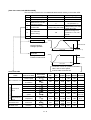
2.2 System configuration drawing
Refer to the User's Manual for details on the wiring.
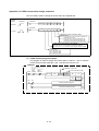
2.2.1 Q172CPU(N) system
Q172
Q61P-Ao Qn(H) Q172
CPU CPU(N) LX
Manual pulse
generator input
unit
PLC CPU/
motion CPU
Synchronous
encoder input
unit
Main base unit
(03oB)
Servo external
signal input unit
Motion CPU control unit
Q172
EX
Q173
PX
QI60 QXoo/
QYoo
Q input/output unit or
special function unit
100/200VAC
Input/output (max. 256 points)
Battery unit
Q170BAT
External interrupt input (16 points)
MITSUBISHI
LITHIUM BATTERY
P
Personal computer
(PC/AT compatible model)
Serial ABS synchronous
encoder cable
(MR-JHSCBLoM-H)
USB/RS232
E
Communication
cable
(Q170CDCBLoM/
Q170BDCBLoM)
SSCNET
SSC I/F card/board
(A30CD-PCF/A30BD-PCF
/A10BD-PCF)
External input signal
• FLS
• RLS
• STOP
• DOG/CHANGE
:
:
:
:
Manual pulse generator 3 units/module
(MR-HDP01) (max. one unit)
Serial ABS synchronous encoder 2 units/module
(MR-HENC) (max. 4 units)
Number of input
points
Upper stroke limit
Lower stroke limit
Stop signal
Near-point DOG / speed/position
control changeover
Points for 8 axes/
unit (max. 1 unit)
Terminal
resistor
SSCNET cable
d1
SSCNET1 system
d2
d3
dB
Panel personal computer
(WinNT/Win98/Win2000)
Personal computer link SSC environment
Expansion
cable
Power
supply unit
Expansion base
(Q6oB)
M
M
M
M
E
E
E
E
MR-H-BN/MR-J2-B/MR-J2S-B/MR-J2M-B/MR-J2-03B5 type
Maximum eight servo amplifier axes
Expansion bases
up to seven stages
2-3
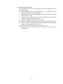
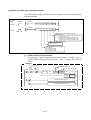
2.2.2 Q173CPU(N) system
Q172
Q61P-Ao Qn(H) Q173
CPU CPU(N) LX
Manual pulse
generator input
unit
PLC CPU/
motion CPU
Synchronous
encoder input
unit
Main base unit
(03oB)
Servo external
signal input unit
Motion CPU control unit
Q172
EX
Q173
PX
QI60
QXoo/
QYoo
Q input/output unit or
special function unit
100/200VAC
Input/output (max. 256 points)
External interrupt input (16 points)
Line divider
Personal computer
(PC/AT compatible model)
P
MITSUBISHI
LITHIUM BATTERY
Serial ABS synchronous
encoder cable
(MR-JHSCBLoM-H)
USB/RS232
E
Communication
cable
(Q170CDCBLoM/
Q170BDCBLoM)
SSCNET
SSC I/F card/board
(A30CD-PCF/A30BD-PCF
/A10BD-PCF)
External input signal
• FLS
• RLS
• STOP
• DOG/CHANGE
Manual pulse generator 3 units/module
(MR-HDP01) (max. one unit)
Serial ABS synchronous encoder 2 units/module
(MR-HENC) (max. 6 units)
Number of input
points
: Upper stroke limit
: Lower stroke limit
: Stop signal
: Near-point DOG / speed/position
control changeover
Points for 8 axes/
unit (max. 4 units)
SSCNET4 system
SSCNET cable
SSCNET3 system
SSCNET2 system
Terminal
resistor
Panel personal computer
SSCNET1 system
(WinNT/Win98/Win2000)
Personal computer link SSC environment
Expansion
cable
dB
d1
Terminal
resistor
dB
d1
Terminal
resistor
dB
dB
d1
M
M
M
M
M
M
M
M
E
E
E
E
E
E
E
E
Power
supply unit
(Q6oB)
d1
Terminal
resistor
MR-H-BN/MR-J2-B/MR-J2S-B/MR-J2M-B/MR-J2-03B5 type
Maximum 32 servo amplifier axes
Expansion bases
up to seven stages
Remarks
To connect eight or more servo amplifier axes:
(1) Use a line divider (Q173DV), or
(2) Use a branch cable (Q173J2B∆CBLoM/Q173HB∆CBLoM)
2-4
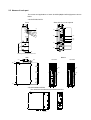
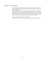
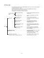
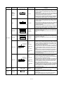
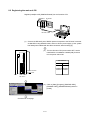
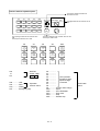
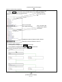
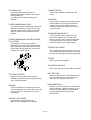
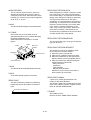
2.3 Names of each part
The names and applications of each Q172CPU(N)/Q173CPU(N) part are shown
below.
• Q172CPU/Q173CPU
Front
State with front cover opened
Q17m CPU
2)
MODE
RUN
ERR.
M.RUN
BAT.
BOOT
MODE
RUN
ERR.
M.RUN
BAT.
BOOT
9)
3)
4)
5)
ON SW
6)
FRONT
SSCNET
1
2
3
4
5
10)
7)
13)
STOP RUN
CN2
14)
RESETL CLR
CN1
PULL
15)
USB
11)
RS-232
12)
8)
Catch finger here and pull to open cover
Side
21)
Bottom
20)
Q172CPU
Q173CPU
1)
16)
18)
18)
19)
19)
17)
• Q172CPUN/Q173CPUN
The names are the same as Q172CPU/Q173CPU.
2-5
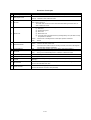
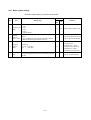
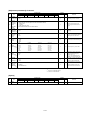
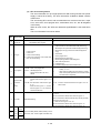
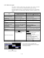
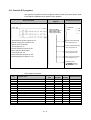
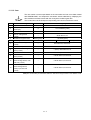
Functions of each part
No.
Item
1)
Module fixing hook
2)
Mode judgment LED
Function
• Hook for fixing module onto base unit. (One-touch attachment)
• Green
: Normal mode
• Orange : Installation mode, ROM write mode
• ON : Motion CPU normally started
3)
4)
RUN LED
ERROR LED
• OFF : Motion CPU error.
Turns OFF when an error is found in the check before starting the motion CPU, or
when a WDT error occurs.
• ON : This LED turns ON when the following errors occur
(1) WDT error
(2) System setting error
(3) Servo error
(4) Motion SFC error
(5) Turns ON when a self-diagnosis error (excluding battery error) that does not stop
the operation is detected.
• Flicker : Flickers when a self-diagnosis error that stops operation is detected.
5)
6)
MOTION RUN LED
BAT.ALARM LED
• OFF
: Normal
• ON
: Turns ON during motion control execution.
• Flicker : Flickers at the start of latch clear.
• OFF
: Turns OFF when motion control is not being executed, and when a self-diagnosis
error that stops operation is detected.
• ON
: Turns ON when a battery error occurs. (When using external battery.)
• ON
: During normal mode ROM operation
• OFF
: During normal mode RAM operation, installation or ROM write mode
7)
BOOT LED
8)
Module mounting lever
• Lever for mounting modules onto base unit.
9)
Memory card EJECT button
• Used to eject memory card.
10)
Memory card connection
connector
• Connector for connecting memory card to CPU. (Use of memory card depends on software
package.)
11) USB connector
12) RS-232 connector
• Connector for connecting USB-compatible peripheral devices. (Connector type B)
• Connect with USB-dedicated cable.
• Connector for connecting peripheral devices.
• Connect with RS-232 connection cable (QC30R2).
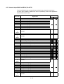
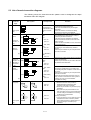
2-6
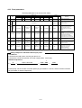
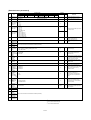
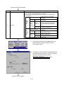
Q173CPU(N)/Q172CPU(N) switch and connector functions
No.
Item
Function
DIP switches 1
Use prohibited (OFF at shipment from maker)
DIP switches 2
ROM operation setting (OFF at shipment from maker)
SW3 SW2
OFF OFF
→ RAM operation mode
→ Setting prohibited
OFF ON
ON
OFF
→ Setting prohibited
ON
ON
→ ROM operation mode
DIP switch
DIP switches 3
ON SW
1
2
13)
DIP switches 4
Use prohibited (OFF at shipment from maker)
DIP switches 5
Install/ROM write switches
ON : Install/ROM write mode
OFF : Normal mode (RAM operation mode/ROM operation mode)
This switch is turned ON in the following cases:
• When installing the CPU module operating system (OS) from a
peripheral device.
• When writing the programs and parameters stored in the RAM into
the ROM for ROM operation.
To change the mode, change the switch setting and then restart the
system.
3
4
5
14)
RUN/STOP
(momentary switch)
• Use this switch by setting it to RUN or STOP.
RUN : The motion program is executed.
STOP : The motion program is stopped.
RESET/L.CLR switch*
(momentary switch)
• RESET : The hardware is reset when the switch is set to the RESET side once.
When an operation error occurs, the error is reset, and the operation is initialized.
• L.CLR : All data in the latch area, set with the parameters, is cleared (set to OFF or 0).
(Data other than that in the latch area is cleared simultaneously.)
Latch clear operation methods
(1) Set the RUN/STOP switch to STOP.
(2) Set the RESET/L.CLR switch to the L.CLR side several times until the MOTION RUN LED
flickers.
(MOTION RUN LED flicker: Preparation for latch clear completed.)
(3) Set the RESET/L.CLR switch to the L.CLR side again. (MOTION RUN LED turns OFF.)
1
15)
16) Module fixing screw hole
• Screw hole used to fix module onto base unit. (M3×12 screw: prepared by user)
17) Module fixing projection
• Projection used to fix module to base unit.
18) CN2 connector
• Connector for establishing SSCNET connection with personal computer.
• Connector for connecting with MR-H-BN/MR-J2S-B/MR-J2-B/MR-J2M-B/MR-J2-03B5.
2
19) CN1 connector*
3
20) Cooling fan connector*
4
21) Cooling fan unit*
• Connector for connecting Q172CPU/Q173CPU dedicated cooling fan unit (Q170FAN).
• Q172CPU/Q173CPU dedicated cooling fan unit (Q170FAN)
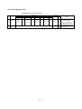
*1: With the multi-CPU system, the QCPU/motion CPU for units No. 2 to No. 4 cannot be reset independently. When reset, MULTI CPU
DOWN (error code: 7000) will occur in the other machines, and the entire multi-CPU system will stop. To reset the entire system, reset
the No. 1 unit's QCPU.
*2: When using the Q173, the signals for the SSCNET1 to 4 systems are input in the CN1 connector. These must be branched to each
system using a line divider Q173DV or a branch cable (A173J2B∆CBLoM/Q173HB∆CBLoM).
*3: Do not remove the caution plate until the cooling fan unit (Q170FAN) is used.
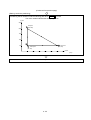
*4: Conditions for using cooling fan unit (Q170FAN):
Controller peripheral temperature
40°C or less
40°C or more,
55°C or less
Cooling fan not
required
Cooling fan required
Number of Q motion CPUs in use
One Q172CPU/Q173CPU module
Two or more Q172CPU/Q173CPU modules
Q172CPUN/Q173CPUN
Cooling fan required
Cooling fan not required
Point
1) Turn the power OFF before setting the install switch.
2) After setting the switch, turn the power ON and check the switch state.
3) In the default state, the switch is set as shown above. (n) indicates the setting.
4) After setting the switch. Turn the power ON and check the switch state.
2-7
MEMO
2-8
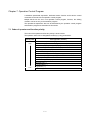
Chapter 3 Q-PLC Multi-CPU
Using the sequence program, the input/output unit and special function unit sequence
control is executed, and operations are executed with the applicable commands and
dedicated commands.
The SFCS (motion SFC start request) command to start the motion SFC program,
GINT change command to execute the interrupt against motion CPU, DDRD and
DDWR commands to read/write the device directly from/to the motion CPU, and the
SVST commands, CHGA current value change, CHGV speed change and CHGT
torque change commands to request the servo program for start are executed.
The Q172 specifications are explained in this chapter.
(For details on the SVST, CHGA, CHGV and CHGT commands, refer to Appendix 5.)
3-1
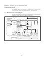
3.1 Multi-CPU system
The multi-CPU system is configured by mounting multiple Q-PLC CPUs/Q motion
CPUs (maximum, 4 units) on the main base unit, and is used to control the input/output
unit and intelligent function unit using each Q-PLC CPU/Q motion CPU.
Since the complicated servo control is executed by the Q motion CPU, and the other
mechanical control and information control are executed by the Q-PLC CPU, it is
possible to distribute the processing load.
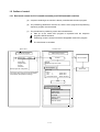
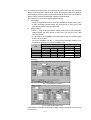
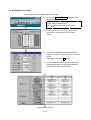
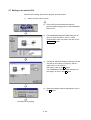
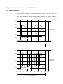
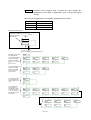
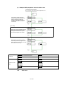
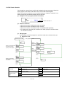
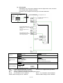
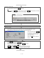
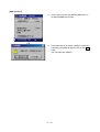
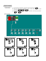
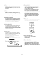
3.1.1 Setting the multi-CPU system
0
1
2
3
4
5
6
7
Input unit 1
Input unit 1
Output unit 1
Output unit 1
Input unit 2
Input unit 2
Output unit 2
Q-PLC CPU 1
Power supply unit
CPU
Q motion CPU 2
For the multi-CPU system, it is necessary to set (control CPU setting) which input/
output unit and intelligent function unit are controlled by which Q-PLC CPU/Q motion
CPU as well as the number of Q-PLC CPUs/Q motion CPUs to be mounted. This must
be set for each Q-PLC CPU/Q motion CPU.
(The operation procedure for multi-CPU setting are explained in the section 8.4.2.)
Set CPU to be
controlled
Control with sequence
program of Q-PLC CPU
(No. 1 machine)
Control with motion SFC program of Q
motion CPU (No. 2 machine)
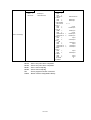
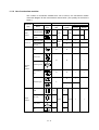
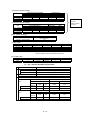
When initialization is executed, the Q motion CPU compares the parameters shown in
the following table with the parameters in the No. 1 machine’s Q-PLC. If the
parameters do not match, they must be changed as shown below to prevent errors.
No.
Comparison item
1
Unit control CPU machine
2
Total number of bases
Base No.
3
Base unit
4
Number of CPUs
5
Operation mode at CPU
stop error
6
Number of automatic refresh
points
Number of
base slots
Parameter
Name for Q motion CPU
Name of Q-PLC CPU
Motion slot setting
Control CPU
I/O
assignment
setting
Base setting
Multi-CPU
setting
Basic setting
Number of
multi-CPUs
Operation
mode
Automatic
refresh
setting
3-2
Multi-CPU
setting
Number of
CPUs
Operation
mode
Automatic
refresh
setting
Remarks
Only the unit No.
set on the Q motion
CPU side is
compared.
Not compared
when the base
setting is not
executed on the QPLC CPU side.
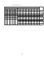
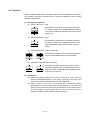
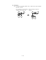
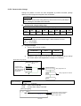
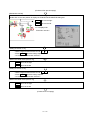
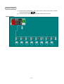
3.1.2 Mounting position of Q-PLC CPU/Q motion CPU
It is possible to mount up to four Q-PLC CPU/Q motion CPUs in the CPU slots (located
at right side of power supply unit) up to the slot No. of main base unit sequentially.
It is not possible to leave an open slot between the Q-PLC CPU and Q-PLC CPU,
between Q-PLC CPU and Q motion CPU, or between Q motion CPU and Q motion
CPU.
Group and mount the Q motion CPU in the right-hand slot of Q-PLC CPU.
(The Q-PLC CPU cannot be mounted at the right of the Q motion CPU.)
(The personal computer CPU can be mounted at the right of the Q motion CPU.)
Mounting position of Q-PLC CPU/Q motion CPU
Number of
Q motion CPU
1
Q motion CPU
3
CPU
0
1
Q-PLC CPU
Q-PLC CPU
Q motion CPU
Q motion CPU
2
3
Personal
computer CPU
Power supply
unit
Power supply
unit
Q motion CPU
2
Personal
computer CPU
1
Q motion CPU
Q motion CPU
0
2
Q motion CPU
Q motion CPU
2
Q-PLC CPU
1
Q-PLC CPU
Q-PLC CPU
1
2
Q-PLC CPU
Q-PLC CPU
0
Q-PLC CPU
0
Personal
computer CPU
Q-PLC CPU
Q-PLC CPU
CPU
Q motion CPU
Q-PLC CPU
1
Power supply
unit
0
Power supply
unit
CPU
2
2
CPU
3-3
1
Q motion CPU
Q-PLC CPU
0
0
Q motion CPU
Q-PLC CPU
CPU
CPU
Power supply
unit
1
Powersupply
unit
Q motion CPU
2
0
CPU
Power supply
unit
4
2
CPU
Power supply
unit
3
1
Q-PLC CPU
0
Power supply
unit
2
CPU
Q-PLC CPU
Mounting position of Q-PLC CPU/Q motion CPU
CPUs
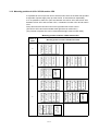
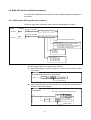
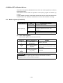
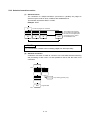
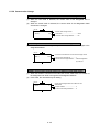
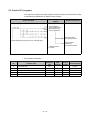
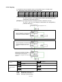
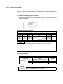
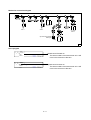
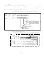
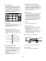
3.1.3 Input/output numbers
With the multi-CPU system, the slots equivalent to the number of CPUs set in the PC
parameter multi-CPU setting are occupied by the Q-PLC CPU/Q motion CPU.
The input/output numbers are assigned sequentially to the right with the input/output
unit and intelligent function unit (mounted at the right slot occupied by the Q-PLC CPU/
Q motion CPU) assigned as "0H".
Q-PLC CPU: When the number of PLC CPUs is set to "2 units"
Q-PLC CP
Q motion CP
Power supply unit
0 1 2 3 4 5 6 7
Input/output No.: 0H
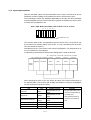
The Q motion CPU I/O No. is independent of that of Q-PLC CPU. It is the I/O No. set
by Q motion CPU system setting. (The I/O No. of a unit controlled by the Q motion
CPU is indicated as "PX/PY".)
Note that the I/O No. of a Q motion CPU control unit assigned in "I/O assignment of QPLC" is invalid even if it is assigned.
It is basically recommended to execute such setting that it is serial in all CPUs.
No. 1 machine No. 1 machine No. 2 machine No. 2 machine
control uni
control uni
control uni
No. 1 machine No. 2 machine con rol uni
Q02HCPU
Q172CPU
Power
supply
QX41
X0 to X1F
QY41
QX41
QY41
Y20 to Y3F PX0 to PX1F PY20 to PY3F
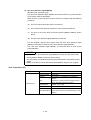
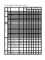
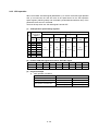
When assigning the Q-PLC CPU I/O, set the Q motion CPU control unit as shown in
the following table. (The Q172LX and Q172EX are treated to occupy the 32 intelligent
function unit points in the Q-PLC CPU.)
Unit
Type
Input unit
Input
Output unit
Output
Number of points
Set depending on unit
used
Set depending on unit
used
Remarks
• Set the control CPU to the
machine corresponding to
Q motion CPU.
• The type and number of
Input/output
Set depending on unit
points do not need to be
mixed
used
set.
Interrupt
16 points
Q172LX
Intelligent
32 points
Q172EX
Intelligent
32 points
Input/output mixed unit
Interrupt unit (Q160)
3-4
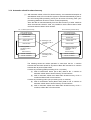
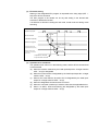
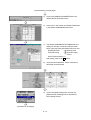
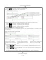
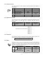
3.1.4 Automatic refresh for shared memory
(1) With automatic refresh of the CPU shared memory, the transmission/reception of
data between each CPU of multi-CPU system is executed automatically by the QPLC CPU during END processing, and by the Q motion CPU during main cyclic
processing (dead time other than motion control) respectively.
Since the data is read automatically from the device memory of other machines
when the automatic refresh is used, it is possible to use the device data of other
machines as device data of local machine.
No. 1 machine (Q-PLC CPU)
No. 2 machine (Q motion CPU)
CPU shared memory
Local machine operation
information area
CPU shared memory
Local machine operation
information area
System area
System area
No. 1 machine automatic
refresh area
User free area
(3) Reading by cycli
processing of No. 2
machine
(1) Writing by END
processing of No. 1
machine
For No. 2 machine
User free area
(2) Writing by main cycli
processing of No. 2
machine
Device memory
For No. 1 machine
No. 2 machine automatic
refresh area
Device memory
(4) Reading by END
processing of No. 1
machine
For No. 1 machine
For No. 2 machine
.
The following shows the outline operation in case when the No. 1 machine
executes the automatic refresh for 32 points of B0 to B1F and the No. 2 machine
executes the 32 points of B20 to B3F.
Contents of processing (END processing of No. 1 machine)
(1) Shift of transmission device (B0 to B1F) data for No. 1 machine to
automatic refresh area of shared memory of local machine
(4) Shift of automatic refresh area data within shared memory of No. 2
machine to B20 to B3F of local machine
Contents of processing (main cyclic processing of No. 2 machine)
(2) Shift of transmission device (B20 to B3F) data for No. 2 machine to
automatic refresh area of shared memory of local machine
(3) Shift of automatic refresh area data within shared memory of No. 1
machine, to B0 to B1F of local machine
3-5
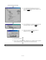
(2) To execute automatic refresh, it is necessary for Q-PLC CPU with the multi-CPU
setting of PC parameter, and for the Q motion CPU with the multi-CPU setting of
basic setting to set the number of points transmitted by each CPU, and the device
(device used to execute the automatic refresh) to store the data.
The head device can be set in the following two ways.
1) Auto setting
• When the applicable device is set at the head device setting column (1)
of each automatic refresh setting, the head device of each CPU is set
automatically with the device as the head.
2) Manual setting
• When "*" is set at the head device setting column (1) of each automatic
refresh setting, the head device of each CPU can be set at the (2)
column optionally.
• It is possible to set a 'DUMMY' at the head device (2) of a machine other
than the local machine.
To set the 'DUMMY', set the "*". Note that the automatic refresh is not
executed for machine to which the 'DUMMY' is set.
Transmission range of each CPU
CPU
Shared memory G of CPU
No. of points (*)
Head
Final
CPU side device
Head device
1
Head
Final
No. 1 machine
2
No. 2 machine
2
No. 3 machine
2
No. 4 machine
2
The following shows a setting example of automatic refresh for outline
operation.
No. 1 machine (Q-PLC CPU)
No. 2 machine (Q motion CPU)
(The operation procedure for automatic refresh setting is explained in the sections
8.4.2 and 9.3.)
3-6
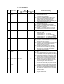
3.2 Multi-CPU motion dedicated commands
The multi-CPU’s dedicated commands (SFCS, GINT, DDRD, DDWR) are explained in
this section.
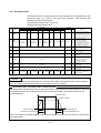
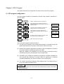
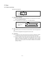
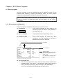
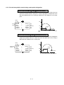
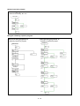
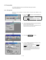
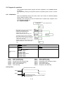
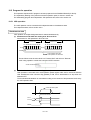
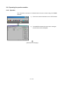
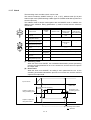
3.2.1 SFCS motion SFC program start command
The SFCS (SFC start) command is used to start the designated SFC program.
[Command
symbol]
[Execution
condition]
Execution command
SP.SFCS
SP.SFCS (n1)
(n2)
(D1)
(D2)
S.SFCS (n1)
(n2)
(D1)
(D2)
Execution command
S.SFCS
Device to store completion status
Completion device
(D1+0): Device to be turned on by one-scan at comm
start acception process complet
(D1+1): Device to be turned on by one-scan at command
start acception error completed (D1+1 is als
turned on after completion of error.)
SFC program No. to be started
K0 to K255
D0 to D8191
W0 to W1FFF
Head input/output No. of CPU
of object machine ÷ 16
No. 2 machine: 3E1H
No. 3 machine: 3E2H
No. 4 machine: 3E3H
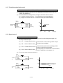
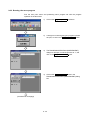
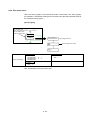
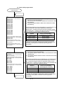
(1) Setting the SFC program No.
The SFC program No. can be set directly or indirectly.
(a) When setting directly, the SFC program No. is set as a direct numeric value
(k0 to k255).
Example
SFC program No. 50 is set as shown below.
SP.SFCS H3E1
K50
M0
D5000
Direct setting
(b) When setting indirectly, the SFC program No. is set with the word device (D0
to D8191, W0 to W1FF) details.
Example
To set D4000
No. of SFC program to be started (0 to 255)
MO
S.SFCS
D4000
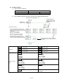
D4000
K
M100
D5000
Indirect setting
3-7
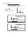
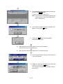
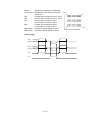
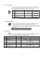
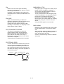
(2) Execution timing
Starting of the designated SFC program is requested at the rising edge (OFF →
ON) of the SFCS command.
The SFC program to be started can be any task setting in the Normal task
execution or NMI task execution.
It is effective at all times including the real mode, virtual mode and during mode
switching.
Sequence program
END
END
END
END
SFCS command
executio
SFCS command
ON
Command accept flag
Motion SFC program
Motion SFC executio
ON
Command start accep
completed device (D1+0)
ON: Only at completion of error
Display of status upon
completion of command
start accep
Completion of command
accept at motion CPU side
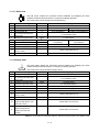
(3) Operation error conditions
The operation error will occur in the following cases, and the SFCS command will
not be executed.
(a) When the machine reserved by the head input/output No. of target machine
CPU ÷ 16 (nl) is designated
(b) When the local machine is designated by the head input/output No. of target
machine CPU ÷ 16 (nl)
(c) When a CPU other than the Q motion CPU is designated by the head input/
output No. of target machine CPU ÷ 16 (nl)
(d) When the designated command name is incorrect
(e) When the command is made up of a device other than the applicable device
(f) When 0 to 3DFH, 3E4H and following are designated by the head input/
output No. of target machine CPU ÷ 16 (nl)
3-8
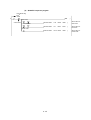
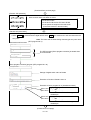
3.2.2 GINT interrupt command to other machine’s CPU
The command is used to generate an interrupt to the Q motion CPU.
[Command
symbol]
[Execution
condition]
Command
SP.GINT
(n1)
(n2)
S.GINT
(n1)
(n2)
SP.GINT
Command
S.GINT
Interrupt pointer No. (0 to 15)
Head input/output No. of object machi
CPU ÷ 16
No. 2 machine: 3E1H
No. 3 machine: 3E2H
No. 4 machine: 3E3H
(1) Setting the GINT command interrupt pointer No.
Set the interrupt pointer No. directly by numerical value (K0 to K15).
Example
The interrupt pointer No.3 is set as follows.
SP.GINT H3E1
K3
Setting of execution interrupt
pointer No.
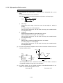
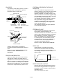
(2) Execution timing
An interrupt is generated to the Q motion CPU at the rising edge (OFF → ON) of
the GINT command.
When an interrupt is generated from the Q-PLC CPU, the Q motion CPU starts a
process with th "PLC interrupt" in respect to the active step of the SFC program.
It is effective at all times including the real mode, virtual mode and during mode
switching. When the Q motion is in DI (interrupt disable), the event processing is
not executed until the EI (interrupt enable) command is executed.
Sequence program
END
END
END
GINT command
execution
GINT command
ON
Command accept
flag
Other machine interrupt
sequence execution process
Interrupt sequence
of other machine
GINT command execution
SM391 (GINT
command execution
completion flag)
GINT command non-execution
3-9
END
(3) Operation error conditions
The operation error will occur in the following cases, and the SFCS command will
not be executed.
(a) When 0 to 3DFH, 3E4H and following are designated by the head input/
output No. of target machine CPU ÷ 16 (nl)
(b) When the local machine is designated by the head input/output No. of target
machine CPU ÷ 16 (nl)
(c) When a CPU that does not support GINT command is designated by the
head input/output No. of target machine CPU 16 (nl)
(d) When the machine reserved by the head input/output No. of target machine
CPU ÷ 16 (nl) is designated
3 - 10
3.2.3 Read from DDRD Q motion CPU device command
The command is used to directly read the device data in the Q motion CPU with QPLC CPU.
[Command
symbol]
[Execution
condition]
Command
SP.DDRD (n1) (S1) (S2) (D1) (D2)
SP.DDRD
Command
S.DDRD (n1) (S1)
(S2) (D1) (D2)
S.DDRD
Device to be turned on by one scan upon
completion of comm
Head device of local machine, to which data to be read is
stored
Head device of object machine to which data to be read is stored
Head device of local machine, to which control data is stored
(S1+0): Status at completion of command is stor
0: Non error
Other than 0: Error code
(S1+1): The number of data to be read is set.
Setting range: 1 to 16
Head input/output No. of target machi
CPU ÷ 16
No. 2 machine: 3E1H
No. 3 machine: 3E2H
No. 4 machine: 3E3H
(1) Setting the number of data points to be read
Set the number of data points to be read indirectly.
Example
To read the data for 10 points from D0 of No. 2 machine to D100 and following
of local machine (No. 1 machine), it is executed as follows.
Setting the number of
read data
SP.DDRD
H3E1
D50
MOV
K10
D51
D0
D100
M0
(2) Execution timing
The data of designated device is read to the Q motion CPU at the rising edge
(OFF → ON) of the DDRD command execution command.
Sequence progra
CPUn interrupt accept fla
(buffer memory at
command accep
destination)
END
END
END
ON
END
DDRD command accept
OFF
ON
OFF
S.DDRD command
ON
DDRD command
completion device
Status display device at
completion of DDRD
command
OFF
Abnormal
ON completion
OFF
OFF Normal
completion
DDRD command
completion (with response)
3 - 11
(3) Operation error conditions
The operation error will occur in the following cases, in which the DDRD
command is not executed.
(a) When the local machine reserved by the head input/output No. of target
machine CPU ÷ 16 (nl) is designated
(b) When the local machine is designated by the head input/output No. of target
machine CPU ÷ 16 (nl)
(c) When a CPU other than the Q motion CPU is designated by the head input/
output No. of target machine CPU ÷ 16 (nl)
(d) When the designated command name is incorrect
(e) When the command is made up of a device other than the applicable device
(f) When 0 to 3DFH, 3E4H and following are designated by the head input/
output No. of target machine CPU ÷ 16 (nl)
(g) When the number of read data items is other than 1 to 16
(h) When the number of read data items exceeds the range of the read data
storage device
3 - 12
3.2.4 Write to DDWR Q motion CPU device command
This command is used to directly write the device data in the Q motion CPU to the QPLC CPU.
[Command
symbol]
[Execution
condition]
Command
SP.DDWR (n1) (S1) (S2) (D1) (D2)
SP.DDWR
Command
S.DDWR (n1) (S1)
(S2) (D1) (D2)
S.DDWR
Device to be turned on by one scan upon
completion of comm
Head device of target machine No., to whic
data to be written is stored
Head device of local machine to which data to be writt
is stored
Head device of local machine, to which control data is stor
(S1+0): Status at completion of command is stor
0: Non error
Other than 0: Error c
(S1+1): The number of data to be written is set.
Setting range: 1 to 16
Head input/output No. of target machi
CPU ÷ 16
No. 2 machine: 3E1H
No. 3 machine: 3E2H
No. 4 machine: 3E3H
(1) Setting the number of data points to be written
Set the number of data points to be written, indirectly.
Example
To write the data for 10 points from D0 of local machine (No. 1 machine) to
D100 and following of No. 2 machine, it is executed as follows.
Setting the number of
write data
SP.DDWR
H3E1
D30
MOV
K10
D31
D0
D100
M0
(2) Execution timing
The data of designated device is written to the Q motion CPU at the rising edge
(OFF → ON) of the DDWR command execution command.
Sequence progra
CPUn interrupt accept fla
(buffer memory at
command accep
destination)
END
END
END
ON
END
DDWR command accep
OFF
ON
OFF
S.DDWR comman
ON
DDWR command
completion device
Status display device at
completion of DDWR
command
OFF
Abnormal
ON completion
OFF
OFF Normal
completion
DDWR command
completion (with response)
3 - 13
(3) Operation error conditions
The operation error will occur in the following cases, and the DDWR command
will not be executed.
(a) When the local machine set for reservation by the head input/output No. of
target machine CPU ÷ 16 (nl) is designated
(b) When the local machine is designated by the head input/output No. of target
machine CPU ÷ 16 (nl)
(c) When a CPU other than the Q motion CPU is designated by the head input/
output No. of target machine CPU ÷ 16 (nl)
(d) When the designated command name is incorrect
(e) When the command is made up of a device other than the applicable device
(f) When 0 to 3DFH, 3E4H and following are designated by the head input/
output No. of target machine CPU ÷ 16 (nl)
(g) When the number of write data items is other than 1 to 16
(h) When the number of write data items exceeds the range of write data
storage device
3 - 14
Chapter 4 Q Motion CPU
This CPU holds the system setting data and servo data, and executes the servo
program and mechanism support language for multi-axis positioning.
4.1 System settings
This setting selects the base and units to be used, and determines the axis No. and the
servo amplifier and servomotor types.
(1) An example of the Q172CPU(N) system settings is shown below. Refer to section
9.3 System settings in Chapter 9 for details on creating the screen.
Motion main base setting
Motion unit setting
External servo amplifier setting
(MR-H-B, MR-J2(S)-B)
Regenerative
resistor setting
Servomotor
axis No. setting
4-1
4.2 Servo data
The following types of data are provided. Default values are set and must be changed
to data that matches the system.
The data is stored in the motion CPU's memory area (SRAM battery backup).
One axis data and parameter block must be set.
The limit switch output data is created as required.
System setting
data
Basic system setting.................. This is the basic operation data for Q
motion CPU
Multi-CPU setting ...................... This is the data related to the multiCPU
Axis data
Fixed parameter ........................ This is fixed data determined
(Axis 1 to 8)
according to the machine system for
each axis.
Servo parameter........................ This is data determined by the
(Axis 1 to 8)
specifications of the servomotor
controlling each axis.
Zero point return data ................ This is data for the zero point return
(Axis 1 to 8)
direction, method and speed, etc., for
each axis.
Data
JOG operation data ................... This is the data for the JOG speed
(Axis 1 to 8)
limit and applicable parameter block
No. for each axis.
Parameter block........................................................... This is the zero point return data, JOG
(Block No. 1 to 64)
operation data and
acceleration/deceleration time data
used in the servo program.
Limit switch output data................................................ The ON/OFF pattern is output to the
(maximum number of output points: 32)
output devices (X, Y, M, L, B).
4-2
4.2.1 Basic system setting
The basic system setting contents are shown below.
Default
No.
Item
Setting range
Initial
value
Units
Remarks
0: 0.8ms
1: 1.7ms
1
Operation cycle 2: 3.5ms
setting
3: 7.1ms
5
ms
0
–
• Set the motion operation cycle.
4: 14.2ms
5: Automatic setting
Operation
2
setting for
STOP → RUN
0: Turns on M2000 when the switch is changed from STOP to
RUN.
1: Turns on M2000 when the switch is changed from STOP to
• Set such condition as to turn on
the PLC READY flag (M2000).
RUN and the setting register (D704) is set to "1".
• Set the bit device for
3
Emergency
0: No setting
stop input
1: X (PX)
(0 to 1FFF)
setting
2: M
(0 to 1FFF)
0
–
emergency stop.
• Bit device OFF → While
emergency stop input is ON
• Bit device ON → While
emergency stop input is OFF
4
Latch range
setting
Sets the range (latch (1)) that can be cleared using latch clear
key and the range (latch (2)) that cannot be cleared using latch
clear key.
4-3
–
–
• Set the latch range for devices
(M, B, F, D, W) respectively.
4.2.2 Multi-CPU setting
The multi-CPU setting contents are shown below.
Default
No.
Item
Setting range
Initial
value
1
Number of
multi-CPUs
0: 2
1: 3
0
–
–
–
2: 4
Automatic
2
refresh setting
It is possible to set the devices (D, W, M, Y, B) by up to 2K
for each multi-
words per each CPU against the setting (1 to 4).
Remarks
Units
• Set the total number of multiCPUs including Q-PLC.
• Automatic refresh setting for
each CPU using shared
memory of multi-CPU
CPU
• Select whether or not to stop
Operation
3
setting for CPU
stop error
the entire system at CPU stop
Note that the selective items depend on the number of CPUs
set with the number of multi-CPUs.
–
–
error. Set for each CPU.
• Always set for the No. 1
machine; selection cannot be
canceled.
4-4
4.2.3 Fixed parameters
The fixed parameters to be set are shown below.
Setting range
No.
2
3
UNIT SETTING
Movement amount per
pulse (A)
1
Item
mm
Setting range
Units
inch
Setting range
0
–
1
PULSE/
TURN
(AP)
MOVEMENT/
TURN
(AL)
4
BACKLASH
5
STROKE LIMIT
MAX.
6
STROKE LIMIT
MIN.
7
CMD. IN-POS.
RANGE
Default
degree
Units Setting range Units
–
2
–
PULSE
Setting range Units
3
–
1 to 65535PLS
0.1 to 6553.5
0.0 to 6553.5
–214748364.8
to
214748364.7
–214748364.8
to
214748364.7
0.1 to
214748364.7
µm
µm
µm
µm
µm
0.00001 to
0.65535
0.0 to 0.65535
–21474.83648
to
21474.83647
–21474.83648
to
21474.83647
0.00001 to
21474.83647
inch
0.00001 to
0.65535
degree
inch
0.0 to 0.65535
degree
inch
0 to
359.99999
degree
inch
0 to
359.99999
degree
inch
0.00001 to
359.99999
degree
1 to 65535
0 to 65535
–2147483648
to
2147483647
–2147483648
to
2147483647
1 to
2147483647
PLS
Remarks
Initial value
Units
3
–
20000
PLS
• Set the number of feedback pulses
per motor rotation.
20000
PLS
• Set the movement amount per
motor revolution, which is
determined by the mechanical
system.
• Set the command unit in
positioning control for each axis.
PLS
0
PLS
• Set the amount of backlash in the
machine.
• Every time the positioning direction
changes during positioning,
compensation by the backlash
compensation amount is executed.
PLS
2147483647
PLS
• Set the upper limit for the machine
movement amount.
PLS
0
PLS
• Set the lower limit for the machine
movement amount.
PLS
• Set the position at which the
command in-position signal
M2403+20n is turned ON
[(Positioning address) –
(Feed present value)].
PLS
100
Setting example for "Movement amount per pulse"
<Conditions>
• The ball screw lead is 8mm, and the gear ratio is 1/2.
• Servomotor: HC-MFS13 (number of encoder output pulses: 131072 pls)
<Relative expression>
1
Lead × Gear ratio
4000
AL
8000 × 2
A=
=
=
=
131072
AP
Number of encoder output pulses
131072
Consequently, set the number of encoder pulses (AP) per rotation to '131072', and the movement amount
(AL) per rotation to '4000.0' respectively.
4-5
4.2.4 Servo parameters
The parameters to be set are shown below.
[Basic servo parameters
Setting range
No.
1*
2*
3*
4*
5*
6
7
Item
mm
Setting range
Units
inch
Setting range
Default
degree
Units Setting range Units
PULSE
Setting range Units
Initial value
Remarks
Units
AMP. SETTING
RESISTANCE
DYNAMIC
BRAKE
MOTOR TYPE
MOTOR
Set automatically in accordance with the system settings
CAPACITY
MOTOR
REVOLUTION
(R)
FEEDBACK
PULSE (N)
• Set the direction of rotation as seen
from the load side.
8*
SPIN
DIRECTION
9
AUTO
1
TUNING*
10
11
0: Forward rotation (CCW) when the positioning address increases.
1: Reverse rotation (CW) when the positioning address decreases.
0
0: VELOCITY
1: POS. & VEL.
2: NONE
0: Interpolation mode
GAIN
1: Auto tuning mode 1
ADJUSTMENT
2: Auto turning mode 2
MODE
3: Manual mode 1
3
SELECTION*
4: Manual mode 2
SERVO
1 to 12 (MR-H-B(N))/15(MR-J2S-B, MR-J2M-B)/5(MR-J2-B) (invalid during automatic tuning)
RESPONSE
1*
–
2
Forward rotation:
Reverse rotation:
• Set the gain (speed/position,
speed) for executing automatic
setting.
–
1
–
• Sets the gain at which the
automatic setting is executed.
For details of each mode, refer to
the following.
1
–
• Set in order to increase servo
responsiveness.
*1: Cannot be set with MR-J2S-B and MR-J2M-B.
*2: For MR-J2(S)-B and WR-J2M-B, the default will be "2".
*3: Cannot be set with MR-H-B(N) and MR-J2-B.
[Gain adjustment mode selection]
Set the gain for executing automatic setting.
• Interpolation mode : Fixes the position control
gain 1/speed control gain 1.
• Auto tuning mode 1 : Normal auto tuning
• Auto tuning mode 2 : Fixes the load inertia ratio.
• Manual mode 1
: Executes the simplified
manual adjustment.
• Manual mode 2
: Executes the adjustment
of all gains manually.
Interpolation
mode
LOAD INERTIA
RATIO
¡
¡
¡
¡
¡
¡
¡
¡
¡
¡
¡
¡
¡
GAIN 1
GAIN 2
VEL. INTEGRAL
COMPS.
¡
¡
VELOCITY LOOP
VELOCITY LOOP
Mode 1 Mode 2 Mode 1 Mode 2
¡
CONTROL GAIN 1
GAIN 2
Manual
¡
POSITION
POSITION LOOP
Auto tuning
¡: Items to be set automatically
POINT
When the items marked with * in the above table are changed, reset the Q-PLC
CPU or turn off the PLC READY (M2000) and turn it on again before turning the
servo power supply on.
4-6
[Adjustment parameters]
When real-time auto tuning is enabled, the values (No.1 to No.6) are tuned and changed
during test operation.
Read the values from the servo amplifier to the personal computer, and then write
them in the Q172CPU(N) before turning OFF the system power supply.
Setting range
No.
Item
mm
Setting range
Units
inch
Setting range
Default
degree
Units Setting range Units
PULSE
Setting range Units
Initial value
LOAD INERTIA
RATIO
POSITION
CONTROL
GAIN 1
VELOCITY
LOOP GAIN 1
(MR-H-B (N)/MR-J2-B)
0.0 to 100.0
(MR-J2S-B, MR-J2M-B)
0.0 to 300.0
(MR-H-B (N)/MR-J2-B)
Valid range 4 to 1000 rad/sec
(MR-J2S-B, MR-J2M-B)
Valid range 4 to 2000 rad/sec
Setting range 1 to 9999 rad/sec
(MR-H-B (N)/MR-J2-B)
Valid range 20 to 5000 rad/sec
(MR-J2S-B, MR-J2M-B)
Valid range 20 to 8000 rad/sec
Setting range 1 to 9999 rad/sec
4
POSITION
LOOP GAIN 2
(MR-H-B (N)/MR-J2-B)
Valid range 1 to 500 rad/sec
(MR-J2S-B, MR-J2M-B)
Valid range 1 to 1000 rad/sec
Setting range 1 to 9999 rad/sec
5
VELOCITY
LOOP GAIN 2
(MR-H-B (N)/MR-J2-B)
Valid range 20 to 8000 rad/sec Setting range 1 to 9999 rad/sec
(MR-J2S-B, MR-J2M-B)
Valid range 20 to 20000 rad/sec Setting range 1 to 99999 rad/sec
600*
6
VEL.
INTEGRAL
COMPS.
Valid range 1 to 1000 ms
7
NOTCH
7
FILTER*
0: Not used
1: 1125
2: 750
3: 562
8
FEED
FORWARD
GAIN
0 to 100%
0: Feed forward control is not executed.
1
2
3
9
IN-POSITION
8
RANGE*
10
MAGNETIC
BRAKE OUT
11
MON. OUT.
MODE
(MON. 1)
12
MON. OUT.
MODE
(MON. 2)
13
OPTIONAL
FUNCTION 1
9
(CARRIER)*
14
15
OPTIONAL
FUNCTION 1
(ENCODER
TYPE)
OPTIONAL
FUNCTION 1
(EXT. EMRG
10
STOP SIG)*
0.1 to 3276.7
1
3.0*
2
3
inch
0.00001 to
0.32767
degree
1 to 32767
PLS
(MR-J2-B)
0: VEL. (±)
1: TRQ. (±)
2: VEL.(+)
3: TRQ. (+)
4: CUR CMD. OUT
5: CMD F∆T
6: DEV. PULSE 1/1
7: DEV. PULSE 1/16
8: DEV. PULSE 1/64
9: DEV. PULSE 1/256
10: DEV. PULSE 1/1024
(MR-J2S-B, MR-J2M-B)
0: VEL. (±)
1: TRQ. (±)
2: VEL.(+)
3: TRQ. (+)
4: CUR CMD. OUT
5: CMD F∆T
6: DEV. PULSE 1/1
7: DEV. PULSE 1/16
8: DEV. PULSE 1/64
9: DEV. PULSE 1/256
10: DEV. PULSE 1/1024
11: Bus voltage
–
• Set the ratio of moment of load
inertia for the motor.
rad/
sec
• Set to increase the follow-up with
respect to the position command.
rad/
sec
• Set to increase the follow-up with
respect to the speed command.
• Set to increase the position
response with respect to load
disturbance.
rad/
sec
rad/
sec
• Set when vibration is generated, for
example in machines with a large
backlash.
20*
ms
• Set the time constant for integral
compensation.
0
Hz
• Set the frequency for the notch
filter.
0
%
• Set the feed forward coefficient
used in positioning control.
6
0 to 1000ms
(MR-H-B (N)/MR-J-B)
0: VEL. (±)
1: TRQ. (±)
2: VEL. (+)
3: TRQ. (+)
4: CUR CMD. OUT
5: CMD F∆T
6: DEV. PULSE 1/1
7: DEV. PULSE 1/4
8: DEV. PULSE 1/16
9: DEV. PULSE 1/32
25*
5
Setting range 1 to 9999 ms
0.00001 to
0.32767
1200*
4
4: 450
5: 375
6: 321
7: 281
µm
70*
Remarks
Units
100
PLS
100
ms
0
–
• Sets the quantity of droop pulses in
the deviation counter.
• The in-position signal is ON when
the number of droop pulses is
within the set range.
1 ≤ (in-position range) ×
AP/AL·AM ≤ 32767
• Set the time delay between
actuation of the electromagnetic
brake and base disconnection.
• Set the monitor items output as
analogue outputs in real time.
1
–
0: 2.25kHz (non low-noise operation)
3: 9kHz (low-noise operation)
0
kHz
0: 2 LINES
1: 4 LINES
0
–
• Set the type of encoder cable.
0: USE
1: NO-USE
0
–
• To invalidate the external
emergency stop signal (EMG) set
"not used".
1
* : For MR-J2S-B and MR-J2M-B, the default is "48".
2
* : Setting not possible for MR-J2S-B and MR-J2M-B.
* : For MR-J2 (S)-B and MR-J2M-B, the default is "7.0".
* : For MR-J2S-B and MR-J2M-B, the default is "35".
• Set the "low noise" to improve the
sound of the frequencies generated
from the motor.
6
7
3
* : The display of the possible setting range differs according to the electronic gear value.
4
* : Cannot be set with MR-J2 (S)-B and MR-J2M-B.
5
* : Cannot be set with MR-H-B (N).
* : For MR-J2S-B and MR-J2M-B, the default is "117".
* : For MR-J2S-B and MR-J2M-B, the default is "35".
* : For MR-J2S-B and MR-J2M-B, the default is "817".
8
9
10
4-7
[Adjustment parameters] Continued
Setting range
No.
Item
mm
Setting range
Units
inch
Setting range
Default
degree
Units Setting range Units
PULSE
Setting range Units
Initial value
Units
Remarks
16
OPTIONAL
FUNCTION 2
(NON MOTOR
9
SELECT)*
0: NO
1: YES
0
–
• To check the status without
connecting a motor, set "YES".
17
OPTIONAL
FUNCTION 2
(MAGNETIC
BRAKE
INTERLOCK
9
TIMING)*
0: TIMING ARE AS FOLLOWS (NOT RELATED WITH MOTOR SPEED)
• SERVO OFF
• ALARM
• EMG. STOP OFF (YES)
1: ABOVE MENTIONED STATUS & ZERO SPEED
0
–
• Set the interlock timing for the
electromagnetic brake interlock
signal.
18
OPTIONAL
FUNCTION 2
(VIBRATION
10
CONTROL)*
0: NO
1: YES
0
–
• Set "YES" to suppress vibration on
stopping.
19
OPTIONAL
FUNCTION 2
(MOTOR
LOCK)
0: NO
1: YES
0
–
• To carry out test operation without
rotating the motor, set "YES".
20
NOTCH
10, 11
DEPTH* *
0
dB
• Set the depth to decrease the gain.
0
Hz
• Set the frequency of notch filter.
0: –40dB
1: –14dB
2: –8dB
3: –4dB
0: NO
1: 4500
2: 2250
3: 1500
4: 1125
5: 900
6: 750
7: 642.9
21
NOTCH
FREQUENCY
10, 11
* *
22
LOW-PASS
FILTER
0: YES
SELECTION
1: NO
10, 11
* *
23
24
ADAPTIVE
VIBRATION
CONTROL
10, 11
* *
ADAPTIVE
VIBRATION
CONTROL
SENSITIVITY
10, 11
* *
8: 562.5
9: 500
10: 450
11: 409.1
12: 375
13: 346.2
14: 321.4
15: 300
16: 281.3
17: 264.7
18: 250
19: 236.8
20: 225
21: 214.3
22: 204.5
23: 195.7
24: 187.5
25: 180
26: 173.1
27: 166.7
28: 160.1
29: 155.2
30: 150
31: 145.2
0
–
0: NO
1: YES
2: HOLD
0
–
0: NORMAL
1: HIGH SENSITIVITY
0
–
• When set to "YES," a filter in the
band of speed control gain 2
setting value × 10
2π × (1+ Non-applicable inertia
setting value is automatically set.)
• Set "YES" for section that always
detects machine resonance
frequency and generates filter
corresponding to the resonance.
• Set the sensitivity at which the
machine resonance is detected.
9
* : Cannot be set with MR-J2 (S)-B and MR-J2M-B.
10
* : Cannot be set with MR-H-B (N).
11
* : Cannot be set with MR-J2-B.
[Option]
Setting range
No.
1
Item
CLAMP
SPEED 0
mm
Setting range
Units
inch
Setting range
Default
degree
Units Setting range Units
1 to 65535 r/min
4-8
PULSE
Setting range Units
Initial value
Units
1000
–
Remarks
• Measure the clamp speed.
[Extended servo parameters]
Setting range
No.
1
2
3
4
5
Item
mm
Setting range
(MR-H-B(N)
–9999 to 9999 mv
(MR-H-B(N)
–9999 to 9999 mv
0: 1.77
BEF. ALRM.
DATA SELECT 1: 3.55
2: 7.11
(SAMPLING
1
3: 14.22
TIM SEL.)*
4: 28.44
BEF. ALRM.
0: VEL. (±)
DATA SELECT 1: TRQ. (±)
(DATA SEL.
2: VEL. (+)
1
3: TRQ. (+)
1)*
4: CUR CMD. OUT
5: CMD F∆T
BEF. ALRM
6: DEV. PULSE 1/1
DATA SELECT
7: DEV. PULSE 1/4
(DATA SEL.
8: DEV. PULSE 1/16
1
2)*
9: DEV. PULSE 1/32
10: DEV. PULSE 1/64
ZERO SPEED
7
EX. ERROR
1 to 1000 kPLS
ALARM LEVEL
9
CLOSED PLG.
TURN
ZERO STD.
PLG
OPTIONAL
FUNCTION 5
(PI-PID CTRL.
CHG.)
OPTIONAL
FUNCTION 5
(SERVO READ
1
LANG)*
Default
degree
Units Setting range Units
MON. OUT. 1
OFFSET
MON. OUT. 2
OFFSET
6
8
Units
inch
Setting range
PULSE
Setting range Units
Initial value
Units
0
mv
0
mv
0
ms
0
–
1
–
MR-J2(S)-B, MR-J2M-B
–999 to 999 mv
MR-J2(S)-B, MR-J2M-B
–999 to 999 mv
0 to 10000 r/min
10000
8.0
Remarks
• Set the offset value for monitor
output 1.
• Set the offset value for monitor
output 2.
• Set the analogue data output when
an alarm occurs.
• Set the speed at which the motor
speed is judged to be "0".
• Set the value at which an
kPLS
excessive droop pulses alarm is
output.
r/min
Refer to the Full Closed Control Reference Manual (IB-67316).
0: INVALID
1: CAN_CHG._BY_DROOP_WHEN_POS. CTRL
2: VEL, AMP, CTRL
0
–
• Set the conditions for PI-PID
control changing.
0: JAPANESE
1: ENGLISH
0
–
• Set the display format for the
parameter unit.
0 to 50000 PLS
0
PLS
–19 to 9979
0
–
980
–
0
bps
16
OPTIONAL
FUNCTION-6
(COMMUNI0: NO
CATION
1: YES
RESPONSE
DELAY TIME)
2 3
* *
0
–
• Set 'YES' for selection of
communication response delay
time when the set-up software is
used.
17
OPTIONAL
FUNCTION-6
(DETECTOR
PULSE
OUTPUT
23
SETTING)* *
0: OUTPUT PULSE
1: DIVIDING RATIO
0
–
• Set the type of detector output
pulse output from communication
connector (CN3).
18
DETECTOR
OUTPUT
2 3
PULSE* *
0 to 65535 PLS
4000
PLS
• Set the detector pulse output from
servo amplifier.
10
11
12
13
14
15
19
20
21
22
23
PI-PID
CHANGE
POSITION
DROOP
TORQUE
COMPS.
1
FACTOR*
VELOCITY
DIFF. COMPS
OPTIONAL
FUNCTION-6
(COMMUNICATION BAUD
2 3
RATE)* *
0 to 1000
0: 9600 bps
1: 19200 bps
2: 38400 bps
3: 57600 bps
MOTOR GEAR
MACHINE
GEAR
CLOSED PLG.
1 2
PULSE* *
RUN-AWAY
DETECTION
FUNCTION-1
RUN-AWAY
DETECTION
FUNCTION-2
Refer to the Full Closed Control Reference Manual (IB-67316).
1
* : Cannot be set with MR-J2 (S)-B and MR-J2M-B.
2
* : Cannot be set with MR-H-B (N).
3
* : Cannot be set with MR-J2-B.
4-9
• Set the amount of position droop at
the change to PI-PID control when
position control is executed.
• Set to expand the torque control
range up to the speed limit value in
torque control.
• Set the differential compensation
value for the actual speed loop.
• Set the serial communication baud
rate in case when the set-up
software is used.
4.2.5 Zero point return data
The data to be set is shown below.
Setting range
No.
Item
mm
Setting range
Units
inch
Setting range
Default
degree
Units Setting range Units
PULSE
Setting range Units
A
DIRECTION
0: REVERSE (CW)
1: FORWARD (CCW)
0
B
METHOD
0: Near-zero point dog method
1: Count method
2: Data set method 1
3: Data set method 2
0
C
ADDRESS
–1
–2147483648 ×10
to 2147483647 µm
0.01 to
mm/
6000000.00
min
–5
–2147483648 to ×10
2147483647
inch
0.01 to
inch/
600000.000
min
–5
PLS
0
0.001 to
2147483.647
×10
–2147483648
degree to 2147483647
degree/
1 to 1000000
min
PLS/
s
1
0 to 35999999
Remarks
Initial value
D
SPEED
E
CREEP
SPEED
0.01 to
6000000.00
mm/
min
0.001 to
600000.000
inch/
min
0.001 to
2147483.647
degree/
min
1 to 1000000
PLS/
s
1
F
MOVEMENT
AFTER DOG
0 to
214748364.7
µm
0 to
21474.83647
inch
0 to
21474.83647
degree
0 to
2147483647
PLS
0
G
P.B. NO.
1 to 64
1
• Sets the direction for zero point return.
• Moves in the designated direction when
zero point return is started.
• Sets the zero point return method.
• The near-zero point dog method or count
method is recommended for a servo
amplifier which does not support absolute
data, and the data set method is
recommended for a servo amplifier which
supports absolute data.
• Sets the present value of the zero point
after zero point return.
• Sets the speed for zero point return.
• Sets the creep speed (low speed
immediately before stopping after
deceleration from zero point return speed)
after the near-zero point dog.
• Sets the movement amount after the nearzero point dog for the count method.
• Set greater than the deceleration distance
at the zero point return speed.
• Sets the parameter block to use for zero
point return (see Section 4.2.7).
* Zero point return is executed with the following servo program example.
Examples
<K 1>
Servo program No.1
The zero point return axis is axis 1
ZERO
Axis 1
Near-point dog method
Zero point
return speed
Count method
Zero point
return speed
Zero point
return direction
Creep speed
t
Creep speed
t
Start
point
Near-point
dog
Zero point
return direction
End
point
Start
point
Near-point
dog
End
point
Zero speed
Zero speed
Moves to the next zero point after the nearpoint dog turns OFF.
Data set method 1
The stopped position
is the zero point.
Near-point dog is not required.
4 - 10
Count
Moves to the next zero point after the
count.
Data set method 2
The actual motor
position is the zero
point.
Near-point dog is not required.
(Suitable for stopper type)
4.2.6 JOG operation data
The data to be set is shown below.
Setting range
No.
Item
A
JOG SPEED
LIMIT
B
P.B. NO.
mm
Setting range
0.01 to
6000000.00
Units
mm/
min
inch
Setting range
0.001 to
600000.000
Default
degree
Units Setting range Units
inch/
min
0.001 to
2147483.647
degree/
min
1 to 64
PULSE
Setting range Units
1 to 1000000
PLS/
s
Initial value
20000
1
4 - 11
Units
Remarks
• Sets the max. speed during JOG
operation.
PLS/ • The JOG speed limit value
s
becomes the JOG operation speed
if the JOG operation speed is set
greater than JOG speed limit value.
• Sets the parameter block number
used for JOG operation.
–
(See section 4.2.7.)
4.2.7 Parameter block
The parameter block is used to determine the acceleration time, deceleration time and
torque limit value, etc., used for zero point return operation, JOG operation and
positioning with the servo program.
The parameter blocks are No. 1 to No. 16.
The data to be set is shown below.
Setting range
No.
Item
mm
Setting range
Units
inch
Setting range
Default
degree
Units Setting range Units
PULSE
Setting range Units
Initial value
1
CONTROL
UNIT
2
SPEED
RESTRICTION
1
*
3
ACCELERATION TIME
1 to 65535ms
1000
4
DECELERATION TIME
1 to 65535ms
1000
5
SHORT STOP
TIME
1 to 65535ms
1000
6
S RATIO
0 to 100%
0
7
TORQUE
1
LIMIT*
1 to 500%
300
8
STOP
METHOD
9
CIRCULAR
ERROR
RANGE
0
–
1
–
2
–
3
–
3
0.01 to
6000000.00
mm/
min
0.001 to
600000.000
inch/
min
0.001 to
2147483.647
degree/
min
1 to 1000000
PLS/
s
200000
0: Deceleration stop executed based on the deceleration time
1: Deceleration stop executed based on the rapid stop deceleration time
0 to 10000.0
µm
0 to 1.00000
inch
0 to 1.00000
degree
PLS
Remarks
• Set the units for compensation
control.
• Can also be used as the units for
–
the command speed and allowable
error range for circular interpolation
set in the servo program.
• Sets the maximum speed for
positioning/zero point return.
PLS/ • If the positioning speed or zero
s
point return speed setting exceeds
the speed limit value, control is
executed at the speed limit value.
• Set the time taken to reach the
ms
speed limit value from the start of
motion.
• Set the time taken to stop from the
ms
speed limit value.
• Set the time taken to stop from the
speed limit value when a rapid stop
ms
is executed.
• Set the S curve ration for S pattern
processing.
• When the S curve ratio is 0%,
%
trapezoidal acceleration/
deceleration processing is
executed.
• Set the torque limit value in the
%
servo program.
• Set the deceleration processing
–
when external signals (STOP, FLS,
RLS) are input.
• Set the permissible range for the
PLS
locus of the arc and the set end
point coordinates.
0
0 to 100000
Units
100
1
* Not used for virtual mode. (Invalid)
POINT
(1) Parameter blocks are designated in the zero point return data, JOG operation data, or servo program.
(2) The various parameter block data can be changed in the servo program
Acceleration time, deceleration time, sudden stop time
As shown below the speed limit value is used as the base. If the positioning command speed is lower than
the speed limit value, the actual acceleration time or actual deceleration time will be shorter than the
commanded time.
V
Speed limit value
Positioning speed
t
Actual deceleration time
Actual acceleration time
Command acceleration time
Command deceleration time
When the positioning command speed is faster than the speed limit value, the axis will move at the speed
limit value speed.
4 - 12
4.2.8 Limit switch output function
This function is used to output the ON/OFF signal corresponding to the range of watch
data set for each output device.
It is possible to set the output device for a maximum of 32 points.
(1) The limit switch output function serves to output the ON to the output device while
the value of watch data is located within the ON output area set by (ON Value)
and (OFF Value).
To execute the limit switch output function, it is necessary to set each data using
the peripheral device.
No.
Item
Received
cycle
Setting range
1
Output device
Bit devices (X, Y, M, L, B)
–
2
Watch data
Motion control data
/Word devices (D, W, #, absolute address)
(16-bit integer type/32-bit integer type/64-bit floating
decimal point type)
3
ON
area
setting
ON Value
Word devices (D, W, #)/Constants (K, H)
OFF
Value
Word devices (D, W, #)/Constants (K, H)
Refresh
cycle
Operation
cycle
Operation
cycle
Operation
cycle
Operation
cycle
Remarks
–
–
–
4
Output permit/
prohibit bit
Bit devices (X, Y, M, L, B, F, special-M)
/None (Default)
Operation
cycle
–
5
Forced output bit
Bit devices (X, Y, M, L, B, F, special-M)
/None (Default)
Operation
cycle
–
ON : Permit
OFF : Prohibit
None : Permit all the time
None : Not output forcibly
all the time
(OFF status)
(2) When the multiple watch data, ON area, output permit/prohibit bit and forced
output bit are set to the same output device, the logical sum of output result is
output in accordance with each setting.
M9074
ON
No setting of output prohibit/permit bit and forced output bit
Output device
OFF Value
ON area setting
ON Value
Watch data value
Setting of output prohibit/permit bit and forced output bit
Output device
Output OFF
Control of output in accordance Output ON Output OFF
with ON Value and OFF Value (forced output)
Output OFF
Control of output in accordance
with ON Value and OFF Value
Permit/prohibit bit
Output OFF
Forced output bit
Output ON
(forced output)
4 - 13
4.3 Positioning control device
The Q motion CPU is provided with positioning control devices for positioning
information.
The explanations of the devices in sections 4.3.1 to 4.3.5 are only for the Q172
specifications.
(Device)
(For Q172)
Each axis status
M2400 to M2559
Each axis command signal
M3200 to M3359
Virtual servomotor axis status
M4000 to M4159
Synchronous encoder axis status
Virtual servomotor axis command
signal
Synchronous encoder axis command
signal
M4640 to M4671
(Details for Q172)
Refer to section 4.3.1.
M4800 to M4939
M5440 to M5471
Internal relay
M2000 to M2319
Refer to section 4.3.2.
Data register
D0 to D1315
Refer to section 4.3.3.
Special relay
M9073 to M9079
Refer to section 4.3.4.
D752 to D799
Special registers
D9180 to D9199
4 - 14
Refer to section 4.3.5.
4.3.1 Status/command signals M2400 to M5471 (For Q172)
Axis command signal
Axis status
The Q172CPU(N) has 8192 internal relay and latch relay points M/L0 to M/L8191. Of
these points, M2400 to M3359 are used to exchange data for each axis. The signal
name and input/output No. for each axis is determined as shown below.
(1) List of M2400 to M3359
(In the virtual mode, the output module is the target instead of the drive module.)
Axis 1
Axis 2
Axis 3
Device
Axis 4 Axis 5
Axis 6
Axis 7
Axis 8
M2400
M2401
M2402
M2403
M2404
M2405
M2406
M2407
M2408
M2409
M2410
M2411
M2412
M2413
M2414
M2415
M2416
M2417
M2420
M2421
M2422
M2423
M2424
M2425
M2426
M2427
M2428
M2429
M2430
M2431
M2432
M2433
M2434
M2435
M2436
M2437
M2440
M2441
M2442
M2443
M2444
M2445
M2446
M2447
M2448
M2449
M2450
M2451
M2452
M2453
M2454
M2455
M2456
M2457
M2460
M2461
M2462
M2463
M2464
M2465
M2466
M2467
M2468
M2469
M2470
M2471
M2472
M2473
M2474
M2475
M2476
M2477
M2480
M2481
M2482
M2483
M2484
M2485
M2486
M2487
M2488
M2489
M2490
M2491
M2492
M2493
M2494
M2495
M2496
M2497
M2500
M2501
M2502
M2503
M2504
M2505
M2506
M2507
M2508
M2509
M2510
M2511
M2512
M2513
M2514
M2515
M2516
M2517
M2520
M2521
M2522
M2523
M2524
M2525
M2526
M2527
M2528
M2529
M2530
M2531
M2532
M2533
M2534
M2535
M2536
M2537
M2540
M2541
M2542
M2543
M2544
M2545
M2546
M2547
M2548
M2549
M2550
M2551
M2552
M2553
M2554
M2555
M2556
M2557
M3200
M3201
M3202
M3203
M3204
M3205
M3206
M3207
M3208
M3220
M3221
M3222
M3223
M3224
M3225
M3226
M3227
M3228
M3240
M3241
M3242
M3243
M3244
M3245
M3246
M3247
M3248
M3260
M3261
M3262
M3263
M3264
M3265
M3266
M3267
M3268
M3280
M3281
M3282
M3283
M3284
M3285
M3286
M3287
M3288
M3300
M3301
M3302
M3303
M3304
M3305
M3306
M3307
M3308
M3320
M3321
M3322
M3323
M3324
M3325
M3326
M3327
M3328
M3340
M3341
M3342
M3343
M3344
M3345
M3346
M3347
M3348
Signal name
Positioning start completed
Positioning completed
In-position
Command in-position
Speed control in progress
Speed/position switching latch
Zero pass
Error detection
Servo error detection
Zero point return request
Zero point return completed
External signal FLS (Upper limit switch)
External signal RLS (Lower limit switch)
External signal (STOP)
External signal DOG/CHANGE
Servo ON/OFF
Torque control in progress
Unusable
Virtual mode continuous operation
M2418 M2438 M2458 M2478 M2498 M2518 M2538 M2558
disabled warning signal
M2419 M2439 M2459 M2479 M2499 M2519 M2539 M2559 M code output in progress
M3209 M3229 M3249 M3269 M3289 M3309 M3329
M3210
M3211
M3212
M3213
M3214
M3215
M3216
M3217
M3218
M3219
M3230
M3231
M3232
M3233
M3234
M3235
M3236
M3237
M3238
M3239
M3250
M3251
M3252
M3253
M3254
M3255
M3256
M3257
M3258
M3259
M3270
M3271
M3272
M3273
M3274
M3275
M3276
M3277
M3278
M3279
Note)
M3290
M3291
M3292
M3293
M3294
M3295
M3296
M3297
M3298
M3299
M3310
M3311
M3312
M3313
M3314
M3315
M3316
M3317
M3318
M3319
M3330
M3331
M3332
M3333
M3334
M3335
M3336
M3337
M3338
M3339
Stop command
Sudden stop command
Forward JOG start
Reverse JOG start
End signal OFF command
Speed/position changeover enabled
Unusable
Error reset
Servo error reset
External STOP input valid/invalid when
M3349
starting
M3350
Unusable
M3351
M3352 Current value update request command
M3353 Address clutch reference setting
M3354 Cam reference position setting
M3355 Servo OFF
M3356
M3357 Unusable
M3358
M3359 FIN signal
Applicable mode
Real
Virtual
–
–
–
–
–
–
–
–
–
–
–
–
–
–
–
–
–
–
–
–
–
–
–
–
–
–
–
–
–
–
–
If servo OFF is turned ON to release the servo lock for each axis, the servo
ON/OFF state will turn OFF and a confirmation can be made.
4 - 15
(2) List of M4000 to M5471
(In the virtual mode, the output module is the target instead of the drive module.)
Device
P1/
E1
Synchronous encoder
P2/ P3/ P4/ P5/ P6/ P7/
E2 E3 E4 E5 E6 E7
Virtual servomotor
P8/
E8
Axis 1
Axis 2
Axis 3
Axis 4
Axis 5
Axis 6
Axis 7
Axis 8
–
M4000
M4001
M4002
M4003
M4004
M4005
M4006
M4007
M4008
to
M4018
M4019
M4020
M4021
M4022
M4023
M4024
M4025
M4026
M4027
M4028
to
M4038
M4039
M4040
M4041
M4042
M4043
M4044
M4045
M4046
M4047
M4048
to
M4058
M4059
M4060
M4061
M4062
M4063
M4064
M4065
M4066
M4067
M4068
to
M4078
M4079
M4080
M4081
M4082
M4083
M4084
M4085
M4086
M4087
M4088
to
M4098
M4099
M4100
M4101
M4102
M4103
M4104
M4105
M4106
M4107
M4108
to
M4118
M4119
M4120
M4121
M4122
M4123
M4124
M4125
M4126
M4127
M4128
to
M4138
M4139
M4140
M4141
M4142
M4143
M4144
M4145
M4146
M4147
M4148
to
M4158
M4159
M4640 M4644 M4648 M4652 M4656 M4660 M4664 M4668
–
–
–
–
–
–
–
–
M4641 M4645 M4649 M4653 M4657 M4661 M4665 M4669
–
–
–
–
–
–
–
–
M4642 M4646 M4650 M4654 M4658 M4662 M4666 M4670
–
–
–
–
–
–
–
–
M4643 M4647 M4651 M4655 M4659 M4663 M4667 M4671
–
–
–
–
–
–
–
–
M4800
M4801
M4802
M4803
M4804
M4805
M4806
M4807
M4808
M4809
M4810
to
M4818
M4819
–
–
–
–
M4820
M4821
M4822
M4823
M4824
M4825
M4826
M4827
M4828
M4829
M4830
to
M4838
M4839
–
–
–
–
M4840
M4841
M4842
M4843
M4844
M4845
M4846
M4847
M4848
M4849
M4850
to
M4858
M4859
–
–
–
–
M4860
M4861
M4862
M4863
M4864
M4865
M4866
M4867
M4868
M4869
M4870
to
M4878
M4879
–
–
–
–
M4880
M4881
M4882
M4883
M4884
M4885
M4886
M4887
M4888
M4889
M4890
to
M4898
M4899
–
–
–
–
M4900
M4901
M4902
M4903
M4904
M4905
M4906
M4907
M4908
M4909
M4910
to
M4918
M4919
–
–
–
–
M4920
M4921
M4922
M4923
M4924
M4925
M4926
M4927
M4928
M4929
M4930
to
M4938
M4939
–
–
–
–
M4940
M4941
M4942
M4943
M4944
M4945
M4946
M4947
M4948
M4949
M4950
to
M4958
M4959
–
–
–
–
–
–
–
–
–
–
Axis command signal
Axis status
–
–
–
–
–
–
–
–
–
M5440 M5444 M5448 M5452 M5456 M5460 M5464 M5468
M5441 M5445 M5449 M5453 M5457 M5461 M5465 M5469
M5442 M5446 M5450 M5454 M5458 M5462 M5466 M5470
M5443 M5447 M5451 M5455 M5459 M5463 M5467 M5471
4 - 16
Applicable mode
Signal name
Positioning start completed
Positioning completed
Unusable
Command in-position
Real
Virtual
–
–
–
Speed control in progress
–
Unusable
–
Error detection
–
Unusable
–
M code output in progress
–
–
–
–
Error detection
External signal TREN detection
Virtual mode continuous operation disabled
warning signal
Unusable
–
Stop command
Sudden stop command
Forward JOG start
Reverse JOG start
End signal OFF command
–
Unusable
–
–
–
Error reset
Unusable
External STOP input valid/invalid when
starting
–
Unusable
–
FIN signal
–
Error reset
–
Unusable
–
P1 to P8
–
–
: Increment synchronization encoder connected to the Q173PX
manual pulse generator input I/F.
E1 to E8
: Absolute synchronous encoder connected to the Q172EX
serial synchronization encoder.
External signal TERN : Detection signal that turns ON when signal is input in Q173PX
tracking I/F.
4 - 17
4.3.2 Internal relays M2000 to M2319 (For Q172)
The Q172CPU(N) has 8192 internal relay and latch relay points M/L0 to M/L8191.
Of these points, M2000 to M2319 are used for positioning control with applications
determined as shown below.
Device No.
M2000
M2001
M2002
M2003
M2004
M2005
M2006
M2007
M2008
M2009
to
M2033
M2034
M2035
to
M2038
M2039
M2040
M2041
M2042
M2043
M2044
M2045
M2046
M2047
M2048
M2049
M2050
M2051
M2052
M2053
M2054
M2055
to
M2060
M2061
M2062
M2063
M2064
M2065
M2066
M2067
M2068
M2069
to
M2100
Signal name
Applicable mode
Real
Virtual
–
–
–
–
PLC READY
Axis 1 start accept flag
Axis 2 start accept flag
Axis 3 start accept flag
Axis 4 start accept flag
Axis 5 start accept flag
Axis 6 start accept flag
Axis 7 start accept flag
Axis 8 start accept flag
Unusable
PC link communication error flag
Unusable
SFC error detection flag
Speed changeover point designation flag
System setting error flag
All-axes servo ON command
Real/virtual mode changeover request
Real/virtual mode changeover status
Real/virtual mode changeover error
Synchronisation deviation error
Motion slot module error
JOG simultaneous start command
All-axes servo ON accept flat
Start buffer full
Manual pulse generator 1 enable
Manual pulse generator 2 enable
Manual pulse generator 3 enable
Operation cycle over flag
Unusable
–
–
–
–
–
–
–
–
Axis 1 speed change flag
Axis 2 speed change flag
Axis 3 speed change flag
Axis 4 speed change flag
Axis 5 speed change flag
Axis 6 speed change flag
Axis 7 speed change flag
Axis 8 speed change flag
Unusable
4 - 18
Device No.
M2101
M2102
M2103
M2104
M2105
M2106
M2107
M2108
M2109
to
M2127
M2128
M2129
M2130
M2131
M2132
M2133
M2134
M2135
M2136
to
M2159
M2160
M2161
M2162
M2163
M2164
M2165
M2166
M2167
M2168
M2169
M2170
M2171
M2172
M2173
M2174
M2175
M2176
to
M2239
M2240
M2241
M2242
M2243
M2244
M2245
M2246
M2247
M2248
to
M2319
Signal name
1-axis synchronous encoder current value change flag
2-axis synchronous encoder current value change flag
3-axis synchronous encoder current value change flag
4-axis synchronous encoder current value change flag
5-axis synchronous encoder current value change flag
6-axis synchronous encoder current value change flag
7-axis synchronous encoder current value change flag
8-axis synchronous encoder current value change flag
Unusable
Applicable mode
Real
–
–
–
–
–
–
–
–
Virtual
–
–
–
–
1-axis automatic deceleration flag
2-axis automatic deceleration flag
3-axis automatic deceleration flag
4-axis automatic deceleration flag
5-axis automatic deceleration flag
6-axis automatic deceleration flag
7-axis automatic deceleration flag
8-axis automatic deceleration flag
Unusable
Output module
axis 1
Output module
axis 2
Output module
axis 3
Output module
axis 4
Output module
axis 5
Output module
axis 6
Output module
axis 7
Output module
axis 8
Main shaft side clutch status
Auxiliary input side clutch status
Main shaft side clutch status
Auxiliary input side clutch status
Main shaft side clutch status
Auxiliary input side clutch status
Main shaft side clutch status
Auxiliary input side clutch status
Main shaft side clutch status
Auxiliary input side clutch status
Main shaft side clutch status
Auxiliary input side clutch status
Main shaft side clutch status
Auxiliary input side clutch status
Main shaft side clutch status
Auxiliary input side clutch status
Unusable
–
–
–
–
–
–
–
–
–
–
–
–
–
–
–
–
–
–
–
–
1-axis speed change [0] accept flag
2-axis speed change [0] accept flag
3-axis speed change [0] accept flag
4-axis speed change [0] accept flag
5-axis speed change [0] accept flag
6-axis speed change [0] accept flag
7-axis speed change [0] accept flag
8-axis speed change [0] accept flag
Unusable
4 - 19
4.3.3 Data registers D0 to D1315 (For Q172)
The Q172CPU(N) has 8192 data register points D0 to D8191.
Of these points, the 1316 points D0 to D1315 are used for positioning control with
applications determined as shown below.
Device
Synchronous encoder
Virtual servomotor
P1/E1 P2/E2 P3/E3 P4/E4 P5/E5 P6/E6 P7/E7 P8/E8
–
–
–
–
–
–
–
–
Axis 1
Axis 2
Axis 3
Axis 4
Axis 5
Axis 6
Axis 7
Axis 8
D0
D1
D20
D21
D40
D41
D60
D61
D80
D81
D100
D101
D120
D121
D140
D141
D2
D3
D22
D23
D42
D43
D62
D63
D82
D883
D102
D103
D122
D123
D142
D143
D4
D5
D24
D25
D44
D45
D64
D65
D84
D85
D104
D105
D124
D125
D144
D145
D6
D26
D46
D66
D86
D106
D126
D146
D7
D27
D47
D67
D87
D107
D127
D147
D8
D28
D48
D68
D88
D108
D128
D148
D9
D29
D49
D69
D89
D109
D129
D149
D10
D30
D50
D70
D90
D110
D130
D150
D11
D31
D51
D71
D91
D111
D131
D151
D12
D32
D52
D72
D92
D112
D132
D152
D13
D33
D53
D73
D93
D113
D133
D153
D14
D34
D54
D74
D94
D114
D134
D154
D15
D35
D55
D75
D95
D115
D135
D155
D16
D36
D56
D76
D96
D116
D136
D156
D17
D37
D57
D77
D97
D117
D137
D157
D18
D38
D58
D78
D98
D118
D138
D158
D19
D39
D59
D79
D99
D119
D139
D159
D640
D642
D644
D646
D648
D650
D652
D654
D641
D643
D645
D647
D649
D651
D653
D655
D725
D726
D727
D704
D705
D706
D707
D708
D709
D710 to D713
D714, D715
D716, D717
D718, D719
D720
D721
(Continued on page 4-22)
4 - 20
D722
D723
D724
Applicable mode
Signal name
Real
Virtual
Current feed value/Roller peripheral speed
Actual current value
Deviation counter
Minor error code
Major error code
Servo error code
Movement amount for repeat zero point return
–
Movement amount after proximity dog ON
Execution program number
–
M code
Torque limit value
Data set pointer for uniform speed control
Movement amount change register
–
Actual current value when STOP is input
–
JOG speed setting
PLC READY flag request
Speed changeover point designation flag request
All-axis servo ON command request
Real/virtual mode changeover request (SV22)
Simultaneous JOG start command request
Unusable
–
–
Simultaneous JOG start axis setting
Register to set axis No. to be controlled by manual
pulse generator 1
Register to set axis No. to be controlled by manual
pulse generator 2
Register to set axis No. to be controlled by manual
pulse generator 3
1 pulse input magnification setting for manual pulse
generator
P1 to P8 : Increment synchronisation encoder connected to the Q173PX manual
pulse generator input I/F.
E1 to E8 : Absolute synchronous encoder connected to the Q172EX serial
synchronisation encoder.
4 - 21
(Continued from page 4-20)
Device
Synchronous encoder
Virtual servomotor
Axis 1
Axis 2
Axis 3
Axis 4
Axis 5
Axis 6
Axis 7
Axis 8
D800
D801
D810
D811
D820
D821
D830
D831
D840
D841
D850
D851
D860
D861
D870
D871
–
–
–
–
–
–
–
–
D1122 D1132 D1142 D1152 D1162 D1172 D1182 D1192
D802
D812
D822
D832
D842
D852
D862
D872
D1123 D1133 D1143 D1153 D1163 D1173 D1183 D1193
D803
D813
D823
D833
D843
D853
D863
D873
D804
D814
D824
D834
D844
D854
D864
D874
D805
D815
D825
D835
D845
D855
D865
D875
D806
D807
D816
D817
D826
D827
D836
D837
D846
D847
D856
D857
D866
D867
D876
D877
D808
D818
D828
D838
D848
D858
D868
D878
D809
D819
D829
D839
D849
D859
D869
D879
D1241
D1251
D1261
D1271
D1281
D1291
D1301
D1311
D1242
D1252
D1262
D1272
D1282
D1292
D1302
D1312
D1243
D1253
D1263
D1273
D1283
D1293
D1303
D1313
D1244
D1254
D1264
D1274
D1284
D1294
D1304
D1314
D1245
D1255
D1265
D1275
D1285
D1295
D1305
D1315
P1/E1 P2/E2 P3/E3 P4/E4 P5/E5 P6/E6 P7/E7 P8/E8
D1120 D1130 D1140 D1150 D1160 D1170 D1180 D1190
D1121 D1131 D1141 D1151 D1161 D1171 D1181 D1191
D1126 D1136 D1146 D1156 D1166 D1176 D1186 D1196
D1127 D1137 D1147 D1157 D1167 D1177 D1187 D1197
–
–
–
–
–
–
–
–
4 - 22
Applicable mode
Signal name
Real
Virtual
Current feed value
–
Current value
–
Minor error code
–
Major error code
–
Unusable
–
–
Unusable
–
–
Current value after main shaft differential gears
–
Error search output axis check No.
–
Unusable
–
–
Execution cam No.
Execution stroke amount
–
Current value within one cam shaft rotation
P1 to P8 : Increment synchronization encoder connected to the Q173PX manual
pulse generator input I/F.
E1 to E8 : Absolute synchronous encoder connected to the Q172EX serial
synchronisation encoder.
4 - 23
4.3.4 Special relays M9073 to M9079, M9104, M9105
The Q172CPU(N) has 256 special relay points M9000 to M9255.
Of these points, the nine points M9073 to M9079, M9104 and M9105 are used for
positioning control with applications determined as shown below.
Device No.
Signal name
M9073
PCPU WDT error flag
M9074
PCPU READY completion flag
M9075
Test mode flag
M9076
Emergency stop input flag
M9077
Manual pulse generator axis setting error flag
M9078
Test mode request error flag
M9079
Servo program setting error flag
M9104
Servo parameter read request flag
M9105
Servo parameter read flag
Applicable mode
Real
Virtual
4.3.5 Special registers D752 to D799, D9017, D9019, D9104, D9180 to D9199 (For Q172)
The Q172CPU(N) has 256 special register points D9000 to D9255.
Of these points, the 71 points D752 to D799, D9017, D9019, D9104 and D9180 to
D9199 are used for positioning control with applications determined as shown below.
Device No.
Signal name
D752
Manual pulse generator (P1) smoothing magnification setting area
D753
Manual pulse generator (P2) smoothing magnification setting area
D754
Manual pulse generator (P3) smoothing magnification setting area
D755
Manual pulse generator 1 permit flag set request
D756
Manual pulse generator 2 permit flag set request
D757
Manual pulse generator 3 permit flag set request
D758
Unusable
D759
PCPU READY flag status
(0: OFF/1: ON)
D760 to D791
Unusable
D792 to D799
Servo amplifier type
D9017
Current main cycle
D9019
Maximum main cycle
D9104
Servo parameter read request axis No.
D9180 to D9181 Unusable
Applicable mode
Real
Virtual
–
–
–
–
–
–
–
–
D9182 to D9183 Test mode request error
D9184
Motion CPU WDT error factor
D9185 to D9187 Manual pulse generator axis setting error
D9188
Motion operation cycle
D9189
Error program number
D9190
Servo program setting error output
D9191 to D9192 Servo amplifier mounting information
D9193 to D9195 Unusable
D9196
PC link communication error
D9197
Motion setting operation cycle
D9198 to D9199 Unusable
4 - 24
POINT
Handling of registers (D704 to D708, D755 to D757)
Since the bit devices shown below cannot be turned ON/OFF for each bit from the Q-PLC CPU, each bit
device is turned ON when the least significant bit is changed from "0" to "1", and is turned off when it is
changed from "1" to "0".
The DDRD and DDWR commands are used to send the request from the Q-PLC CPU.
It is possible to turn ON/OFF the bit devices directly with the motion SFC program
No.
1
2
3
4
5
6
7
8
Functions
PLC READY flag
Speed changeover point designation flag
All-axis servo ON command
Real/virtual mode changeover request (SV22 only)
Simultaneous JOG start command
Manual pulse generator 1 enable flag
Manual pulse generator 2 enable flag
Manual pulse generator 3 enable flag
4 - 25
Bit devices
M2000
M2040
M2042
M2043
M2048
M2051
M2052
M2053
Request registers
D704
D705
D706
D707
D708
D755
D756
D757
4.4 Motion SFC dedicated devices
The motion CPU (PCPU) dedicated devices include the motion registers (#0 to #8191)
and coast timer (FT).
These devices can be used in the operation control (F/FS) program or transition (G)
program.
It is not possible to directly access these devices from the PLC. When the devices are
used at the PLC side, therefore, substitute them for PLC devices before accessing.
4.4.1 Motion registers (#0 to #8191)
Motion devices
Item
Q173CPU(N)/Q172CPU(N)
Number of points
8192 points (#0 to #8191)
Data size
16 bits/point
Latched except for SFC dedicated devices.
Motion register (#)
Latch
(Cleared at all points due to latch clear
operation.)
Applicable task
Normal , event , NMI
Access
READ/WRITE is executable at all ranges.
(1) List of motion registers
These motion registers are common to all OSs.
Device No.
Division of application
#0
User devices
to
(8,000 points)
#8000
SFC dedicated devices
to
(66 points)
#8066
to
#8191
Servo monitor devices
(126 points)
Remarks
Cleared by latch clear.
Cleared only when the power supply is
turned ON and when the operation is reset
using the key.
Not cleared.
POINT
Note that the motion register (#) cannot be set to be used as an indirect
designation device for the mechanism program.
4 - 26
(2) SFC dedicated devices (#8000 to #8191)
The SFC dedicated devices are shown below.
It indicates the refresh cycle for device of which signal direction is "Status", and
the retrieval cycle for device of which signal direction is "Command".
Device
No.
#8000
6th oldest error information
5th oldest error information
#8024
4th oldest error information
#8032
3rd oldest error information
#8040
2nd oldest error information
#8048
Last error information
#8056
Newest error information
#8064
Axis 1 amplifier type
#8065
Axis 1 motor current
Axis 2 amplifier type
#8069
Axis 2 motor current
#8071
Axis 3 amplifier type
#8073
Axis 3 motor current
#8075
Axis 4 amplifier type
#8077
Axis 4 motor current
#8079
#8081
Axis 5 motor current
Axis 6 amplifier type
#8085
Axis 6 motor current
#8087
Axis 7 amplifier type
#8089
Axis 7 motor current
#8091
Axis 8 amplifier type
#8093
Axis 8 motor current
#8095
3.55ms
When amplifier power
supply is turned ON
3.55ms
When amplifier power
supply is turned ON
3.55ms
When amplifier power
supply is turned ON
3.55ms
When amplifier power
supply is turned ON
3.55ms
Axis 7 motor speed
#8092
#8094
When amplifier power
supply is turned ON
Axis 6 motor speed
#8088
#8090
–
3.55ms
Axis 5 motor speed
#8084
#8086
When an error occurs
When amplifier power
supply is turned ON
–
Axis 5 amplifier type
#8083
Received
cycle
3.55ms
Axis 4 motor speed
#8080
#8082
Refresh cycle
When amplifier power
supply is turned ON
Axis 3 motor speed
#8076
#8078
–
Axis 2 motor speed
#8072
#8074
SFC error history
(8 times) (64 points)
Axis 1 motor speed
#8068
#8070
Command
(oldest error information)
#8016
#8067
Status
7th oldest error information
#8008
#8066
Signal direction
Signal name
When amplifier power
supply is turned ON
3.55ms
Axis 8 motor speed
4 - 27
–
(3) SFC error history device
The error information for up to eight past errors after turning ON the CPU power
supply is stored as a history. The error information of #8056 to #8063 contains
newest error.
The error during SFC control, and conventional errors such as minor error, major
error, servo error, servo program error, mode select error, etc., are all integrated
in the history.
When an error occurs, the "SFC error detection signal M2039" is set at the same
time.
The error information is as shown below.
No.
Signal name
+0
Erroneous SFC
program No.
Contents
Error in SFC control
Conventional error
0 to 255 : Erroneous SFC program No.
–1
: Not related to SFC program
–1
3 : Minor/major error
(output module in real mode/virtual mode (SV22 only))
4 : Minor/major error (virtual servomotor shaft) (SV22 only))
5 : Minor/major error (synchronous encoder shaft) (SV22
only))
1 : In case of F/FS
2 : In case of G
1
Error type
–1 : In case of SFC drawing
–2 : In case of K or others (in case of other than
F/FS, G, SFC drawing)
6 : Servomotor
7 : Servo program error
8 : Mode select error (SV22 only)
9 : Manual pulse generator shaft setting error
10 : Test mode request error
11 : PCPWDT error
12 : Personal computer link communication error
2
Error program
No.
0 to 4095 : F/FS, G, K program No.
0 to 255 : GSUB program No.
–1
: Not concerned with F/FS, G, K,
GSUB
3
Error block No.
SFC list line
No./
axis No.
0 to 4095 : Servo program No. when error type is "3 (In real
mode)", "4" or "7"
–1
: Other cases (including zero point return in un-start,
JOG, manual pulse generator, test mode servo start
and start at servo diagnosis)
0 to 8191 : F/FS or block No. (line No.) of
program when the error type is "1" or
"2"
0 to 8188 : SFC list line No. when the error type
is "–2"
–1
: When the error type is "–1", or when
1 to 32 : Axis No. concerned when the error type is "3" to "6"
–1
: Other cases
the error type is "1" or "2" and is not
concerned with block
• Conventional error code (below 16000) when the error type is
"3" to "6"
• Error code stored in D9190 when the error type is "7"
4
Error code
• Error code stored in D9193 (A273UH-S3), D9195 (A172SH)
16000 and following
when the error type is "8"
• -1 when the error type is "9" or "10"
• Error code stored in D9184 when the error type is "11"
• Error code stored in D9196 when the error type is "12"
5
6
Error
occurrence
time
7
Year/
month
Day/
hour
Set the time data (D9025, D9025, D9027) of PLC.
(BCD code, Year: Lower 2 digits of Christian era)
Minute/
second
4 - 28
(4) SFC error detection signal (M2039)
(Refresh cycle: operation cycle)
The SFC error detection signal (M2039) is turned ON when any errors detected
by the motion CPU are generated.
When an error occurs, it is set to the error device in accordance with the following
procedure.
(a) The error code is set to each axis or error device.
(b) The error detection signal of each axis or error device is turned ON.
(c)
The error is set to the "SFC error history device (#8000 to #8063)" shown
above.
(d) The SFC error detection signal (M2039) is turned ON.
For user program, read the error history when the "SFC error detection signal
(M2039)" is turned on to reset the "SFC error detection signal (M2039)".
The "SFC error detection signal (M2039)" is turned ON when an error occurs
newly thereafter.
POINT
• Even if the "SFC (Error detection signal (M2039)" is reset, the "SFC error history
device (#8000 to #8063)" will not be reset (0 clear).
The error history is controlled continuously all the time after turning ON the power
supply.
• Set the clock data and clock data read request (M9028) using the user program.
4.4.2 Coast timer (FT)
Motion device
Item
Q172CPU(N)/Q173CPU(N)
Number of points
1 point (FT)
Data size
32 bits/point (–2147483648 to 2147483647)
No latch
Latch
Coast timer (FT)
Cleared to "0" when the power supply is turned
ON or when the reset key is pressed.
Applicable task
Access
Normal , event , NMI
Only reading is executable.
888µs timer
Timer specifications (The current value (FT) is incremented by 1 every
888µs.)
4 - 29
Memo
4 - 30
Chapter 5 SFC Program
This chapter describes the configuration and each element of the SFC program.
5.1 SFC program configuration
The SFC program consists of a combination of START, step, transition, and END, etc.,
as shown below.
Operation
start
Program name
Positioning
preparation
F0
Step (operation control step): Executes the
• • • • •designated operation control program while the
system is active.
SET Y0=X0+X10
• • • • • D100=W0+W100
Positioning preparation completion check
G0
Transition (shift): Indicates the conditions for
• • • • •shifting control to the succeeding step.
•••••
Execution of
positioning
K0
Step (motion control step): Executes the
• • • • •designated servo program while the system is
active.
ABS-1
• • • • • Axis 1, D100
Speed 10000
Positioning
completion
check
G1
Transition (WAIT): Shows the condition to shift
• • • • •the control to the succeeding step.
•••••
Operation end
END
• • • • •END: Shows the end of program.
• • • • •START: Indicates the start of the program.
Y0+M100
!X0
The running SFC program operates as follows.
(1) The step (F0) is activated, and the designated operation is executed at step (F0)
(positioning preparation). The step in active state is called "Active step".
(2) Whether the conditions designated by transition (G0) are established (or whether
it is ready to start the positioning program) is checked.
When the conditions are established, the active step (F0) is inactivated, and the
succeeding step (K0) is activated (start of servo program K0).
(3) At transition (G1), whether the operation at step (K0) is completed (completion of
servo program K0 positioning) is checked. When the positioning is completed
(conditions established), the control is shifted to the succeeding step.
(4) The control is executed by shifting the active step as shown in the above items (1)
to (3), and ended when END is input.
POINT
The number of steps that can be an active step simultaneously is 256 or less (total
in all SFC programs).
5-1
5.2 List of SFC symbols
The parts that can be a constituent element of SFC program are shown below. The
SFC program expresses the operation sequence and shift control by connecting such
parts with oriented line.
Division
Designation
Symbol
(code size: byte)
List expression
Program name
START
Program name
(0)
Program
start/end
END
(8)
Motion control
step
Kn
• Indicates the start of program with the program name.
• Designates the program name when the subroutine is
called.
• START is limited to one per program.
• Indicates the end of program.
• Returns to the calling source program when a subroutine
is called.
• The multiple ENDS can be set in one program, but it is not
absolutely necessary.
• Starts the servo program Kn (K0 to K4095).
END
END
Function
CALL Kn
(8)
Step
1-time
execution type
operation
control step
Fn
Scan
execution type
operation
control step
FSn
Subroutine
call/start step
CALL Fn
(8)
CALL FSn
• Executes the operation control program FSn (FS0 to
FS4095) repeatedly until the succeeding shift conditions
are established.
(8)
GSUB program
name
Program name
(8)
Clear step
• Executes the operation control program Fn (F0 to F4095)
once.
CLRProgram name
CLR program
name
(8)
• When WAIT follows GSUB, the "subroutine" is called and
the control is shifted to the designated program. When the
END is executed, the control is returned to the calling
source program.
• When a command other than WAIT follows GSUB, the
"subroutine" is started. The designated program is started
causing the control to be shifted to the succeeding (lower)
program. The start source program and start destination
program are executed at the same time, and the start
destination program is stopped when the END is executed.
• Interrupts and ends the designated program that is
running. When a stopped program is restarted, it restarts
from the initial point (start step).
• When the designated program is in "Subroutine call", the
execution of the subroutine program is interrupted.
• When the designated program is located after "Subroutine
start", the execution of the subroutine program is not
interrupted.
• When the "subroutine called" is cleared, the execution of
the designated subroutine is interrupted, and the calling
source program is resumed to shift the operation to the
succeeding step.
POINT
It is possible to set the comment to each symbol such as step, transition, etc. within SFC diagram.
• Program start/end : It is unable to set the comment.
• Step/transition
: Display of 80 single-byte (40 double-byte) characters, 20 characters × 4 lines
• Jump/pointer
: Display of 64 single-byte (32 double-byte) characters, 16 characters × 4 lines
5-2
Division
Designation
Symbol
(code size: byte)
SHIFT
(shifting to
advance
reading)
List expression
Gn
WAITON
bit device
• If the last step is a motion control step, the operation is
shifted to the succeeding step when the shifting conditions
Gn (G0 to G4095) are established without waiting for the
motion to end.
• If the last step is an operation control step, the operation is
shifted to the succeeding step when the shifting conditions
are established after execution of operation.
• If the last step is a subroutine call/start step, the operation is
shifted to the succeeding step when the shifting conditions
are established without waiting for the subroutine to end.
• If the last step is a motion control step, the operation is
shifted to the succeeding step when the shifting conditions
Gn (G0 to G4095) are established without waiting for the
motion to end.
• If the last step is an operation control step, the operation is
shifted to the succeeding step when the shifting conditions
are established after execution of operation. (Same
operation as SHIFT)
• If the last step is a subroutine call/start step, the operation is
shifted to the succeeding step when the shifting conditions
are established without waiting for the subroutine to end.
• Prepares to start the succeeding motion control step, and
outputs the control command as soon as the designated
bit device is turned ON.
• Be sure to set it together with motion control step in pairs
(1:1).
WAITOFF
bit device
• Prepares to start the succeeding motion control step, and
outputs the control command as soon as the designated
bit device is turned OFF.
• Be sure to set it together with motion control step in pairs
(1:1).
SFT Gn
(8)
Gn
WAIT
WAIT Gn
(8)
ON bit device
WAITON
Kn
Function
(14)
OFF bit device
WAITOFF
Kn
Transition
(14)
(When the
conditions fail to
be established)
Gn
SHIFT Y/N
N
(When the Y
conditions are
established)
(When the
conditions fail to
be established)
WAIT Y/N
Jump
JUMP
Gn
N
(When the Y
conditions are
established)
Pn
IFBm
IFT1
SFT Gn
:
JMP IFEm
IFT2
SFT Gn+?
:
JMP IFEm
IFEm
IFBm
IFT1
WAIT Gn
:
JMP IFEm
IFT2
WAIT Gn+?
:
JMP IFEm
IFEm
JMP Pn
• If the last step is a motion control step, the operation is
shifted to the succeeding step when the shifting conditions
Gn (G0 to G4095) are established without waiting for the
motion to end. If the conditions are not established, shifts
to the step connected to the right.
• If the last step is an operation control step, the operation is
shifted to the lower step when the shifting conditions are
established after execution of operation. If the conditions
are not established, shifts to the step connected to the
right.
• If the last step is a subroutine call/start step, the operation is
shifted to the lower step when the shifting conditions are
established before the operation of subroutine is completed.
If the conditions are not established, shifts to the step
connected to the right.
• If the last step is a motion control step, the operation is
shifted to the lower step when the shifting conditions Gn
(G0 to G4095) are established after the operation of
motion is completed. If the conditions are not established,
shifts to the step connected to the right.
• If the last step is an operation control step, the operation is
shifted to the lower step when the shifting conditions are
established after execution of operation. If the conditions
are not established, shifts to the step connected to the
right. (Same operation as SHIFT)
• If the last step is a subroutine call/start step, the operation
is shifted to the lower step when the shifting conditions are
established after the operation of subroutine is completed.
If the conditions are not established, shifts to the step
connected to the right.
• Jumps to the designated pointer Pn (P0 to P16383) within
the local program.
(14)
Pointer
POINTER
Pn
• Indicates the jump destination pointer (label).
• The step, transition, branch point and connection point
can be set.
• P0 to P16383 can be set in one program. The program
No. may be overlapped with another program No.
Pn
(8)
5-3
5.3 List of branch/connection diagrams
The following shows the branch/connection patterns used to designate the steps/
transitions within SFC diagram.
Designation
(code size:
byte)
SFC symbol
List expression
Series shifting
(Each symbol
size)
Selective
branch
IFBm
IFT1
IFT2
(Number of
branches + 2
× 10)
Selective
connection
IFEm
(8)
Function
• Sequentially executes steps and transitions
Refer to the list
connected in a series from the top.
corresponding to
• The steps and transitions may be arranged
symbol shown in SFC
alternately.
diagram of section
• When the transition is omitted, the shifting
5.2.
processing is executed unconditionally.
• Executes the route for which shifting conditions
CALL Kn
are established first after execution of step or
IFBm
transition just before the branch.
IFT1
• The head of branch destination for selective
SFT Gn
branch is limited to transitions, and must be all
CALL Fn
SHIFT or WAIT.
(When the SHIFT and WAIT co-exist, it becomes
:
the parallel branch.)
JMP IFEm
• Shifts to the connection point after execution of
IFT2
processing for route branched by selective
SFT Gn'
branch.
CALL Fn'
• Either step or transition may be used just before
:
and after connection.
( JMP IFEm )
IFEm
Basic type
CALL Fn''
Parallel branch
(Number of
branches × 22 PABm
+ Number of
connections ×
2 + 12)
PAT1
PAT2
Parallel
connection
PAEm
(8)
Jump (shift)
<Normal jump>
SFT Gn
PABm
PAT1
CALL Fn
SFT Gn'
:
JMP PAEm
PAT2
CALL Fn'
SFT Gn''
:
( JMP PAEm )
PAEm
CALL Fn''
:
<Jump (connection)>
CALL Fn
JMP Pn
CALL Fn'
Pn
CALL Kn
(Each symbol
size)
5-4
• Executes the multiple routes (steps) connected in
series simultaneously.
• Either step or transition may be used at the head
of parallel branch destination.
• Waits for completion of execution at each route
branched by parallel branch, and shifts to the
succeeding step after completion of execution for
all routes.
Either step or transition may be used just before
and after connection.
• When the step just before connection is an FS
step, the scan is executed even if the system is
waiting. The scan is not executed after
completion of waiting.
(1) Normal jump
• Shifts the execution to the pointer Pn
designated within local program after
execution of last step or transition.
• Either step or transition may be used at jump
destination.
• Even when the jump is executed from FS
step to transition, the scan is executed while it
is under waiting for establishment of shifting
conditions for jump destination.
(2) Jump (connection)
• "Jump (connection)" occurs when the jump is
executed to the other route within parallel
branch after completion of parallel branch, in
which the waiting is executed at jump
destination.
5.4 SFC program name
Set the "SFC program name" for each SFC program No. 0 to No. 255.
The SFC program name is set within 16 single-byte characters (double-byte: 8
characters). Designate this SFC program name for the "subroutine call/start step
(GSUB)" and the "clear step (CLR)".
POINT
(1) The SFC program can be set to a random number between 0 and 255.
(2) "$ (single byte)" cannot be set as the first character of SFC program name.
(3) "\", "/", ":", ";", ",", ".", "*", "?", " " ", "<", ">", "|" (single byte) cannot be set in the
SFC program name.
5-5
5.5 Steps
5.5.1 Motion control step
Start the servo program Kn.
<Description example> K10
ABS-1
Kn 1 2000
Axis
Speed
10000
Designation range: K0 to K4095
(1) Description of operation
(a) The start accept flag for the axis designated in the designated servo program
Kn (n = 0 to 4095) is turned ON.
(b) The designated servo program Kn (n = 0 to 4095) is started.
Shift condition established
Start accept flag
(M200n)
v
t
(2) Error
In the following case, an error will occur and execution of the SFC program will
stop.
(a) When the designated servo program Kn does not exist.
(3) Precautions
(a) To change the current value within the SFC program, designate the CHGA
command using the servo program and call it at the motion control step.
(b) Even if the major or minor error occurs at or during the start of the servo
program, causing the servo program to be stopped due to error, the SFC
program will executed continuously. If the SFC program must be stopped
when an error occurs, input the error detection conditions at the transition
(shifting condition).
5-6
5.5.2 Operation control step
Execute the operation control program Fn/FSn.
<Description example>
F5
SET Y10 = X0+M0
Fn/FSn
D200 = D0+D1
Designation range: F0 to F4095/FS0 to FS4095
(1) Description of operation
(a) 1-time execution type operation control step Fn
The operation control program Fn (n = 0 to 4095) is executed once.
(b) Scan execution type operation control step FSn
The operation control program FSn (n = 0 to 4095) is executed repeatedly
until the succeeding shifting condition is established.
(2) Error
In the following case, an error will occur and execution of the SFC program will
stop.
(a) When the designated operation control program Fn/FSn does not exist.
(3) Precautions
(a) If the SFC program must be stopped when an error occurs, input the error
detection conditions at the transition (shifting condition).
5-7
5.5.3 Subroutine call/start step
Call/start the SFC program of designated program name.
Program name
(1) Description of operation
(a) The designated SFC program is called and started.
(b) The control may differ depending on the type of transition connected after
the subroutine call/start step.
• WAIT ......................... Subroutine call
• Other than WAIT ........ Subroutine start
MAIN
(1)
SUB
(2)
WAIT
(5)
SUB
(3)
(4)
END
END
MAIN
(1)
SUB
(2)
Shift
(2)
SUB
(3)
END
END
In case of WAIT (subroutine call)
In case of other than WAIT (subroutine start)
(2) Error
In the following case, an error will occur and execution of the SFC program will
stop.
(a) When the designated SFC program does not exist in the called or started
subroutine.
(b) When the called/started SFC program has already been started in a calling/
starting subroutine.
(c) When the local program is called or started in a called or started subroutine.
(3) Precautions
(a) The depth of nesting for subroutine call/start is not limited.
(b) For subroutine start, the start source SFC program is executed continuously
even if the start destination SFC program is stopped due to error.
(c) When the call destination SFC program is stopped due to error in case of
subroutine call, the execution of calling source SFC program is interrupted at
the error.
5-8
5.5.4 Clear step
Interrupt the execution of SFC program of designated program name.
CLR
Program name
(1) Description of operation
(a) The designated SFC program being executed is interrupted.
(b) Even if the SFC program (designated for "Clear") is set to automatic start, it
will not start automatically after interruption.
(c) When the designated program is calling the subroutine, the execution of
subroutine program called is also interrupted.
MAIN
SUB
SUB
WAIT
END
When "subroutine call" is set as shown on the left:
• When MAIN is cleared
Execution of both MAIN and SUB is interrupted.
• When the subroutine (SUB) is cleared
Execution of the subroutine (SUB) is interrupted to return to
MAIN if the subroutine (SUB) is being executed.
END
(d) When the program is designated after a subroutine is started, execution of
the started subroutine program continues.
MAIN
SUB
SUB
Shift
END
When "subroutine start" is set as shown on the left:
• When MAIN is cleared
Even if the subroutine (SUB) is being executed, execution of
MAIN is interrupted. However, execution of the subroutine (SUB)
continues.
• When the SUB is cleared
Execution of only SUB is interrupted if the subroutine (SUB) is
being executed.
END
(2) Error
An error occurs in the following case, in which the execution of SFC program is
interrupted.
(a) When the SFC program designated at clear step does not exist.
(3) Precautions
(a) When the SFC program designated at clear step has not been started, it will
not result in an error in particular, but is ignored.
(b) Even if the execution of SFC program is stopped at the clear step, the output
is held.
5-9
5.6 Transition
Either a conditional expression or operation expression can be described for transition.
The operation expression described here is executed repeatedly until the shifting
condition is established.
(1) Description of operation
(a) Motion control step + Shift
• The operation is shifted to the succeeding step when
the shifting condition Gn is established without waiting
for the servo program Kn (started at the motion control
step) to end.
Kn
Gn
(b) Motion control step + WAIT
• The operation is shifted to the succeeding step when
the shifting condition Gn is established after the servo
program Kn (started at the motion control step) has
ended.
Kn
Gn
(c)
WAITON/WAITOFF + Motion control step
ON M0
OFF M0
Kn
Kn
• The operation is started as soon as the designated bit
device of WAITON/WAITOFF is turned ON/OFF.
(d) Combination with operation control step
Fn
Fn
Gn
Gn
• The SHIFT and WAIT operate in the same manner.
Operation is shifted to the succeeding step when the
shifting condition is established after operation control
program Fn is executed.
(2) Precautions
(a) Always set transition together with motion control step in a pair. If the step
after the WAITON/WAITOFF is not a motion control step, execution of the
SFC program will be interrupted when an error is detected.
(b) When a major or minor error occurs at the start of the servo program
designated at the motion control step, thereby resulting in start failure, the
SFC program is executed continuously, and shifted to the succeeding step. If
the SFC program must be stopped when an error occurs, input the error
detection conditions at the transition (shifting condition).
5 - 10
5.7 Jump/pointer
Pn
Pn
Jump
Pointer
(1) Description of operation
(a) "JUMP" functions to jump to the designated pointer Pn within local program.
(b) The pointer can be set to a step, transition, branch point or connection point.
(c) Pointer Pn can be set between P0 and P1683 in each program.
(2) Precautions
(a) JUMP cannot be set to exit a parallel branch - parallel connection. (Improper
example 1 shown below)
(b) JUMP cannot be set from a parallel branch - parallel connection to a parallel
branch - parallel connection. (Improper example 2 shown below)
(c) A setting that continues the label and jump cannot be set. (Improper example
3 shown below)
Improper example 1
Improper example 2
Improper example 3
Pn
Pn
Pn
Pn
Pn
Pn
5.8 END
END
(1) Description of operation
(a) The program is ended.
(b) When the subroutine is called, the program is returned to the calling source
SFC program.
(2) Precautions
(a) Multiple ENDs can be set in one program.
(b) END cannot be set between a parallel branch - parallel connection.
(c) The output is held even when the SFC program is completed with END.
5 - 11
5.9 Branch/connection
5.9.1 Parallel shifting
The execution is shifted to the step or transition connected in series.
(1) To start a servo program or subroutine, and shift to the succeeding step
before the operation is completed
Set the transition to SHIFT.
In this case, it is possible to omit the transition (shift).
When the transition is omitted, shifting is executed unconditionally.
K1
The servo program K1 is started.
G1
The operation is shifted to the succeeding step when
the condition set for transition G1 is established
without waiting for the servo program K1 to end.
K2
The servo program K2 is started.
(2) To start the servo program or subroutine and advance to the succeeding
step after completion of operation
Set the transition to WAIT.
K1
The servo program K1 is started.
G1
The operation is shifted to the succeeding step when the axis
started by servo program K1 is stopped (start accept flag: OFF)
and the condition designated by transition G1 is established.
K2
The servo program K2 is started.
5 - 12
5.9.2 Selective branch/connection
(1) Selective branch
The conditions for multiple transitions (connected in parallel) are judged to
execute only the route for which conditions are established first.
The transition is limited to SHIFT or WAIT.
Example: WAIT
The servo program K1 is started.
K1
G1
G2
G3
G255
K2
K3
K4
G255
The conditions for transition
(G1 to G255) are judged after
the start axis is stopped (start
accept flag: OFF) to shift to
the established route.
Maximum number of selective branches = 255
POINT
(1) The transition conditions are not always judged from left sequentially.
(2) Selective connection
A selective connection is made to connect to one route after selective branching
and processing of each route. It is also possible to set so that the route is not
connected.
IFB1
Jump shifting (normal jump)
END
Program END
IFE1
5 - 13
5.9.3 Parallel branch/parallel connection
(1) Parallel branch
Multiple steps, connected in parallel, are executed at the same time. Either step
or transition may be used at the head of parallel branch destination.
G0
WAIT G0
K2
K3
F1
F10
G1
G2
G3
G255
The steps from K2 to F10, connected in parallel,
are executed when the conditions set for
transition G0 are established after operation of
last step, and executed thereafter for each route
up to the parallel connection point.
Maximum number of selective branches = 255
POINT
"SHIFT" or "WAIT" can be set for the transition just before parallel branch, but
"WAITON" and "WAITOFF" cannot be set.
(2) Parallel connection
Always connect with a parallel connection when using parallel branching.
Jumping to another branch route can be set between the parallel branch – parallel
connection. In this case, the jump destination will be a parallel connection point in
the middle (connection jump).
A jump that exits the parallel branch – parallel connection cannot be set.
G1
Parallel branch point
PAB1
K2
K4
F10
Jump (connection)
ON M100
G11
K3
F1
ON M100
G12
F12
Waits until the conditions set by transition
G3 are established and the start of servo
program K4 is completed after the servo
program K3 is stopped.
The operation is shifted to the succeeding
(next) step after completion of waiting.
K100
PAE1
Parallel connection point
K5
5 - 14
5.10 Y/N transition
Use the "SHIFT Y/N transition", "WAIT Y/N transition" when the route needs to be
branched according to the establishment of the shift conditions.
(When the
conditions fail to
be established)
Gn
(When the
conditions fail to
be established)
Gn
N
(When the Y
conditions are
established)
N
(When the Y
conditions are
established)
SHIFT Y/N transition
WAIT Y/N transition
(1) Description of operation
(a) The operation is shifted to the lower step when the shifting conditions set by
Gn are established, and to the step connected from right when the shifting
conditions are not established.
(b) The difference between "SHIFT Y/N" and "WAIT Y/N" is the same as that
between "SHIFT" and "WAIT".
(c) This allows the following selective branch program to be described easily.
<Conventional description>
• The G0 program and G1 program are limited only when
the affirmation/negation of conditional expression is
different.
(Example 1)
IFB1
G0
<Current description>
G1
[G 0]
M0
(Example 2)
[G 1]
!M0
[G 0]
D0!=K100
[G 1]
D0==K100
• Set the G0 program shown in the above (Example 1) and
(Example 2).
• The converted SFC program list code is the same as the
conventional description. (Only the SFC diagram
IFB1
G0
expression differs.)
Consequently, the program in which the part of "Automatic
search → Conditional expression of vacant G-No." is
logically negated, is created automatically, causing two Gprograms to be occupied.
IFB1
G0
5 - 15
G1
(2) Precautions
(a) To connect to just before "SHIFT Y/N" or "WAIT Y/N", insert it between
"connection – branch".
• It is not possible to connect directly • Insert "connection - branch" into "SHIFT Y/N" or "WAIT Y/N".
between.
5 - 16
5.11 Task operation
The timing to execute the SFC program can be set once for each program with the
program parameter. The task is roughly classified into three types as shown in the
following table.
Task type
Contents
Normal task
Execution at motion main cycle (dead time)
Event task
1. Execution at constant cycle (0.8ms, 1.7ms, 3.5ms, 7.1ms, 14.2ms)
2. Execution when input set for event task, of external interrupt (16 points
of QI60), is turned ON
3. Execution only by interrupt from PLC
NMI task
Execution when input set for NMI task, of external interrupt (16 points of
(Non-Maskable
QI60), is turned ON
Interrupt)
(1) Normal task
The SFC program is executed at main cycle (dead time) of the Q motion CPU
process.
POINT
(1) Set the SFC program (including motion control step) to "Normal task".
(2) Execution of normal task is interrupted while the event task/NMI task is being
executed.
Note that when using a normal task, an event task prohibit command (DI) can
be described in the operation control step. Thus, interruption of the event task
can be prohibited in the section enclosed by the event task prohibit command
(DI) and event task permit command (EI).
5 - 17
(2) Event task
The event task is used to execute the SFC program when an event occurs.
The event includes the following:
(a) Constant cycle
The SFC program is executed periodically at a cycle of 0.8ms, 1.7ms, 3.5ms,
7.1ms or 14.2ms.
(b) External interrupt (16 points of I0 to I15)
The SFC program is executed when the QI16 (16-point interrupt unit
mounted in motion slot) input set to the event task turns ON.
(c) PLC interrupt
The SFC program is executed when the GINT command is executed by the
sequence program for another units Q-PLC CPU.
POINT
(1) It is possible to set the multiple events in one SFC program. However, multiple
constant cycles cannot be set.
(2) The motion control step cannot be executed during an event task.
(3) NMI task
The SFC program is executed when the external interrupt (16 points of QI60)
input set for the NMI task turns ON.
POINT
(1) The NMI task has the highest priority in normal task/event task/NMI task.
(2) Even if the event task prohibit (DI) is executed by the normal task, the NMI
task interrupt is not masked, but is executed.
(4) Execution status example
The following shows an SFC program execution example when the SFC program
is executed by multiple tasks.
3.5ms
NMI interrupt
NMI interrupt
NMI task execution program
3.5ms event task execution program
Normal task execution program
When there is a program to be executed by the NMI task, a program to be
executed by the 3.5ms constant cycle event task and a program to be executed
by the normal task, each task is executed as shown below.
(a) 3.5ms constant cycle event task is executed every 3.5ms
(b) NMI task is executed at highest priority when the NMI interrupt is input
(c) Normal task is executed during dead time
5 - 18
5.12 SFC parameters
The SFC parameters include "task parameters" used to control the tasks (normal task,
event task, NMI task) and "program parameters" set for each SFC program.
5.12.1 Task parameters
No.
Item
1
Number of
continuous
shift lines
2
Interrupt setting
Normal task
Setting range
Initial value
1 to 30
3
Set either "Event task" or
"NMI task" for external
Event task
interrupt input (I0 to I15).
Remarks
These parameters are retrieved at the
rising edge of the PLC READY signal
(M2000). Then control is executed.
Turn the PLC READY signal (M2000)
OFF before setting or changing those
parameters.
5.12.2 Program parameters
The following parameters are set for each SFC program.
No.
1
Item
Start-up
setting
Setting range
Execution/non-execution of automatic start
Event task
2
Execution
task
NMI task
3
Number of continuous
shift lines
4
END operation
–
* When the event task is set, set the event to be
validated.
Be sure to set one of following (1 to 3).
1. Constant cycle
0.8ms, 1.7ms, 3.5ms, 7.1ms or 14.2ms or none
2. External interrupt (selection from the events set
for event task)
It is possible to set the multiple events from I0 to
I15.
3. PLC interrupt
It is possible to set the multiple events for 1 to 3
shown above.
The same event may be shared by multiple SFC
programs.
* When the NMI task is set, set the interrupt to be
validated.
1. External interrupt (select from the events set for
event task)
It is possible to set the multiple events from I0 to
I15.
1 to 10
* Set the number of continuous shift lines set for the
program set in the event task or NHI task.
End/continue
* Set the operation mode of END step for the
program set in the event task or NMI task.
5 - 19
Initial value
Nonexecution of
automatic
start
Normal task
1
END
Remarks
These parameters
are retrieved at the
rising edge of the
PLC READY signal
(M2000). Then control
is executed.
Turn the PLC READY
signal (M2000) OFF
before setting or
changing those
parameters.
5.13 SFC program start method
The SFC program is executed while the PLC READY M2000 signal is ON.
The SFC program can be started by the following three methods.
(1) Automatic start
(2) Start from SFC program
(3) Start from PLC
The start method is set for each SFC program using the program parameter.
(1) Automatic start
The SFC program is started automatically when the PLC READY M2000 is turned
ON.
(2) Start from SFC program
The SFC program is started when the subroutine is called or the start step is
executed within the SFC program.
(3) Start from PLC
The SFC program is started when the SFCS command is executed within the
sequence program.
5.14 SFC program end method
The SFC program is ended in the following three methods:
(1) End program by executing END set within SFC program.
(2) End SFC program by turning PLC READY signal M2000 OFF.
(3) End with clear step.
POINT
(1) Multiple ENDs can be set within one SFC program.
(2) The SFC program will end even if "Automatic Start" is set.
5 - 20
Chapter 6 SV22 Servo Programs
6.1 Servo program
The servo program is used to designate the type of positioning control and the
positioning data required for carrying out positioning control. The servo program
configuration and designation methods are explained in this section.
With the SV13 and SV22, the servomotor is controlled with this servo program.
However, the servo commands that can be used are listed in the "List of servo
commands".
6.1.1 Servo program configuration
One servo program is configured of the parts (1) to (3) shown below.
(1) Program No. ........................ This number designates the start request in the
sequence program. A random number between 0
0 to 4095
and 4095 can be set.
(2) Servo command.................. This indicates the type of positioning control.
(3) Positioning data .................. This is data required to execute the servo
commands. The data required for execution is
determined or each servo command.
Program No.
<K11>
Servo instruction
ABS-2
AXIS
1,
20000.0
(µm)
AXIS
2,
20000.0
(µm)
SYN. SPEED
DWELL
M CODE
P.B
S RATIO
5000.00
100
3
2
100
(mm/min)
(ms)
(%)
Positioning data
Data other than the axis No. can be
indirectly designated with a word
device (D, W).
P.B. indicates the parameter block
(Operated at block 1 unless it is
set.)
(4) Servo program area
1) The servo program area is used to store the servo program created with a
peripheral device. The memory in the positioning CPU is large enough to
store 14334 steps (14K steps), and is backed up by the SRAM battery.
(This is not the sequence program storage internal memory.)
6-1
6.1.2 List of servo commands
The commands listed below are available, but the usage validity differs according to
the CPU OS.
Positioning data
Linear control
ABS-2
–
–
–
–
–
–
–
–
–
–
–
–
INC-2
5
–
–
–
–
–
–
ABS-3
Absolute 3-axis linear
interpolation
7
–
–
–
–
–
–
INC-3
Incremental 3-axis linear
interpolation
7
–
–
–
–
–
–
8
–
–
–
–
–
–
8
–
–
–
–
–
–
7
–
–
–
–
–
7
–
–
–
–
–
6
–
–
–
–
–
6
–
–
–
–
–
6
–
–
–
–
–
6
–
–
–
–
–
6
–
–
–
–
–
6
–
–
–
–
–
6
–
–
–
–
–
6
–
–
–
–
–
7
–
–
–
–
–
7
–
–
–
–
–
7
–
–
–
–
–
7
–
–
–
–
–
3-axis
ABS-4
INC-4
ABS
Auxiliary
point
designation
INC
ABS
ABS
ABS
ABS
INC
INC
INC
INC
ABS
Center
ABS
point
designation
INC
INC
Absolute 4-axis linear
interpolation
Incremental 4-axis linear
interpolation
Absolute circular
interpolation by auxiliary
point designation
Incremental circular
interpolation by auxiliary
point designation
Absolute circular interpolation by radius designation, within CW180°
Absolute circular interpolation by radius designation,
CW180° and greater
Absolute circular interpolation by radius designation,
within CCW180°
Absolute circular interpolation by radius designation,
CCW180° and greater
Incremental circular interpolation by radius designation, within CW180°
Incremental circular interpolation by radius designation, CW180° and greater
Incremental circular interpolation by radius designation, within CCW180°
Incremental circular interpolation by radius designation, CCW180° and greater
Absolute circular
interpolation by center
point designation, CW
Absolute circular
interpolation by center
point designation, CCW
Incremental circular
interpolation by center
point designation, CW
Incremental circular
interpolation by center
point designation, CCW
Operates as one block if not set
S curve ratio
Deceleration processing
on STOP input
Allowable error range
for circular interpolation
–
Torque limit value
4
Sudden stop
deceleration time
–
Deceleration time
Control unit
–
Acceleration time
Number of pitches
–
Speed limit value
Center point
–
M code
–
Dwell time
–
Command speed
Radius
Address/Travel value
–
5
4-axis
Circular interpolation control
4
Incremental 2-axis liner
interpolation
2-axis
Radius
designation
Parameter block
Auxiliary point
INC-1
Absolute 1-axis
positioning
Incremental 1-axis
positioning
Absolute 2-axis linear
interpolation
Circular/helical
Torque limit value
ABS-1
1-axis
Processing details
Axis
Instruction
symbol
Parameter block No.
Positioning
control
Number of steps
Common settings
: Item that must be set
: Item set as necessary
– : Item that cannot be set
* : Possible
<Number of steps>
The number of steps in each command is the value when the
The step is decremented by one each time a mark item is set.
6-2
mark items are set.
Repeat condition
Program No.
Cancel
Start
Speed change
Others
–
–
–
–
*
–
–
–
–
*
–
–
–
–
*
–
–
–
–
*
–
–
–
–
*
–
–
–
–
*
–
–
–
–
*
–
–
–
–
*
–
–
–
–
–
–
–
–
–
–
–
–
–
–
–
–
–
–
–
–
–
–
–
–
–
–
–
–
–
–
–
–
–
–
–
–
–
–
–
–
–
–
–
–
–
–
–
–
–
–
–
–
–
–
–
–
–
–
–
–
–
–
–
–
–
–
–
–
–
–
SV22
SV22
SV13
for automatic machine for automatic machine
for transfer assembly
Real mode
Virtual mode
mark: Usable
× mark: Not usable
6-3
Positioning data
VF
Reverse
rotation
VR
Forward
rotation
VVF
Reverse
rotation
VVR
Forward
rotation
VPF
Reverse
rotation
VPR
Re-start
VPSTART
VSTART
Speed
changeover
control
(Max. 3 axis)
Position followup control
–
–
–
–
7
–
–
–
–
–
–
Torque limit value
–
Sudden stop
deceleration time
–
Deceleration time
5
Acceleration time
–
Speed limit value
–
M code
–
Dwell time
–
Command speed
–
–
3
–
–
–
–
–
–
–
–
3
–
–
–
–
–
–
–
–
3
–
–
–
–
–
–
–
–
3
–
–
–
–
–
–
–
–
4
–
–
–
–
–
4
–
–
–
–
2
–
1
–
S curve ratio
Deceleration processing
on STOP input
Allowable error range
for circular interpolation
Address/Travel value
–
Axis
4
–
–
–
–
–
–
–
–
–
–
–
–
–
–
–
–
–
–
–
–
–
–
–
–
–
–
–
–
–
–
–
–
–
–
–
–
–
–
–
–
–
–
–
–
–
–
–
–
VEND
Speed changeover
control, end
1
–
–
VABS
Absolute designation of
speed changeover point
4
–
–
–
–
–
–
–
–
–
–
–
–
–
–
–
–
VINC
Incremental designation of
speed changeover point
4
–
–
–
–
–
–
–
–
–
–
–
–
–
–
–
–
–
–
–
–
–
–
PFSTART
CPSTART1
Constant
speed control
Speed control
Reverse rotation start
Speed control II
Forward rotation start
Speed control II
Reverse rotation start
Speed/position
changeover control
Forward rotation start
Speed/position
changeover control
Reverse rotation start
Speed/position
changeover control
Restart
Speed changeover
control, start
Control unit
FEED-3
Speed
control II
Forward
rotation
Number of pitches
3 axis
3 axis linear interpolation
Fixed-dimension feed start
Speed control
Forward rotation start
Center point
FEED-2
Radius
2 axis
1 axis fixed-dimension
feed start
2 axis linear interpolation
Fixed-dimension feed start
Parameter block
Auxiliary point
FEED-1
Circular/helical
Torque limit value
1 axis
Processing details
Parameter block No.
Instruction
symbol
Speed/position
changeover control
Speed
control
Fixed dimension
feed
Positioning
control
Number of steps
Common settings
Position follow-up control
start
1 axis constant speed
control start
4
–
3
–
–
–
–
–
–
–
–
CPSTART2
2 axis constant speed
control start
3
–
–
–
–
–
–
–
–
CPSTART3
3 axis constant speed
control start
4
–
–
–
–
–
–
–
–
–
CPSTART4
4 axis constant speed
control start
4
–
–
–
–
–
–
–
–
–
Uniform speed control end
1
–
–
–
–
–
–
–
–
–
–
–
–
–
–
–
–
–
–
Repetition range head
setting
2
–
–
–
–
–
–
–
–
–
–
–
–
–
–
–
–
–
–
–
3
–
–
–
–
–
–
–
–
–
–
–
–
–
–
–
–
–
–
–
3
–
–
–
–
–
–
–
–
–
–
–
–
–
–
–
–
–
–
–
–
–
–
–
–
–
–
–
–
–
–
–
–
–
–
–
–
–
–
–
–
–
–
–
–
–
–
–
–
–
–
–
CPEND
–
–
FOR-TIMES
For repetition of
uniform control,
speed
changeover
and uniform
speed control
FOR-ON
FOR-OFF
NEXT
Repetition range end
setting
Simultaneous start
(Max. 3 program)
Simultaneous
start
START
Zero point
return
ZERO
Zero point return start
7
OSC
High-speed oscillation
5
High-speed
oscillation
–
Operates as one block if not set
: Item that must be set
: Item set as necessary
– : Item that cannot be set
* : Possible
6-4
–
Repeat condition
Program No.
Cancel
Program
Speed change
Others
–
–
–
–
*
–
–
–
–
*
–
–
–
–
*
–
–
–
–
*
–
–
–
–
*
–
–
–
–
*
–
–
–
–
*
–
–
–
–
*
–
–
–
–
*
–
–
–
–
–
–
–
–
–
–
–
–
–
–
–
–
–
–
–
–
–
–
–
–
–
–
–
–
–
*
–
–
–
–
*
–
–
–
–
*
–
–
–
–
*
–
–
–
–
*
–
–
–
–
–
–
–
–
–
–
–
–
–
–
–
*
–
–
–
–
–
–
–
–
–
–
–
–
SV13
for transfer assembly
SV22
SV22
for automatic machine for automatic machine
Real mode
Virtual mode
×
×
×
mark: Usable
× mark: Not usable
<Number of steps>
The number of steps in each command is the value when the
mark items are set. The step is
decremented by one each time a mark item is set.
<Torque limit value of common item>
For VPF/VPR commands, it is validated after changing to "Position control".
For VABS/VINC commands, it is validated after changing to "Speed control".
<START command>
It is unable to set the program No. indirectly.
6-5
Positioning data
ABS
Helical interpolation control
ABS
Radius
designation
ABS
INC
INC
INC
INC
ABS
Center
ABS
point
designation
INC
INC
–
9
–
–
–
–
9
–
–
–
–
9
–
–
–
–
9
–
–
–
–
9
–
–
–
–
9
–
–
–
–
9
–
–
–
–
10
–
–
–
–
10
–
–
–
–
10
–
–
–
–
10
–
–
–
–
–
–
–
–
–
–
–
–
–
–
–
–
–
–
–
–
–
–
–
–
–
S curve ratio
–
Deceleration processing
on STOP input
Allowable error range
for circular interpolation
–
Torque limit value
–
Sudden stop
deceleration time
9
Deceleration time
–
Acceleration time
–
Speed limit value
–
Control unit
–
Number of pitches
10
Incremental helical
interpolation by auxiliary
point designation
Absolute helical interpolation by radius designation,
within CW180°
Absolute helical interpolation by radius designation, CW180° and greater
Absolute helical interpolation by radius designation, within CCW180°
Absolute helical interpolation by radius designation,
CCW180° and greater
Incremental helical interpolation by radius designation, within CW180°
Incremental helical interpolation by radius designation, CW180° and greater
Incremental helical interpolation by radius designation, within CCW180°
Incremental helical interpolation by radius designation, CCW180° and greater
Absolute helical interpolation by center point
designation, CW
Absolute helical
interpolation by center
point designation, CCW
Incremental helical
interpolation by center
point designation, CW
Incremental helical
interpolation by center
point designation, CCW
Auxiliary point
–
Torque limit value
–
M code
–
Dwell time
–
Command speed
10
Address/Travel value
Absolute helical interpolation by auxiliary point
designation
CPSTART
XYZ
3D orthogonal
interpolation CP start
CPEND
3D orthogonal
interpolation CP end
Servo
CHGA
Servo/virtual servo current
value change
3
–
–
–
–
–
–
–
–
–
–
–
–
–
–
–
–
–
–
Encoder
CHGA-B
Encoder current value
change
3
–
–
–
–
–
–
–
–
–
–
–
–
–
–
–
–
–
–
Cam
CHGA-C
Cam shaft current value
change
3
–
–
–
–
–
–
–
–
–
–
–
–
–
–
–
–
–
–
3D orthogonal
interpolation
Current value change
Center point
ABS
Radius
ABS
Auxiliary
point
designation
INC
Parameter block
Processing details
Axis
Instruction
symbol
Parameter block No.
Positioning
control
Circular/helical
Number of steps
Common settings
–
–
–
–
–
–
Operates as one block if not set
: Item that must be set
: Item set as necessary
– : Item that cannot be set
* : Possible
<Number of steps>
The number of steps in each command is the value when the
The step is decremented by one each time a mark item is set.
6-6
mark items are set.
Repeat condition
Program No.
Cancel
Start
Speed change
Others
–
–
–
–
–
–
–
–
–
–
–
–
–
–
–
–
–
–
–
–
–
–
–
–
–
–
–
–
–
–
–
–
–
–
–
–
–
–
–
–
–
–
–
–
–
–
–
–
–
–
–
–
–
–
–
–
–
–
–
–
–
–
–
–
–
–
–
–
–
–
SV22
SV22
for automatic machine for automatic machine
SV13
for transfer assembly
Real mode
Virtual mode
×
×
×
×
×
×
×
mark: Usable
× mark: Not usable
6-7
6.1.3 Linear control
1 to 4-axis control with ABS-1 to ABS-4 (absolute method)
(1) Using the zero point as a reference, positioning control is carried out from the
current stopped address (address before positioning) to the designated address.
(2) The movement direction is determined according to the currently stopped address
and designated address.
REAL
<K 50>
End
point
ABS-2
1,
AXIS
2,
AXIS
SYN. SPEED
End point
The axis moves to this
point no matter where
the address before
positioning is located.
200
200000.0
200000.0
5000.00
(µm)
(µm)
(mm/min)
100
0
Start
point
0
100
200
300
(mm)
1 to 4-axis linear control with INC-1 to INC-4 (increment method)
(1) Positioning control is carried out from the currently stopped position's address by
the designated movement amount.
(2) The movement direction is determined according to the movement amount sign
(+/–).
1) When movement direction is positive
Forward direction (address increment direction) positioning
1) When movement direction is negative
Reverse direction (address decrement direction) positioning
REAL
<K 51>
Movement
amount
INC-2
1,
AXIS
2,
AXIS
SYN. SPEED
200
100000.0
100000.0
5000.00
(µm)
(µm)
(mm/min)
End point
100
Start point
0
0
50
100
200
300 (mm)
Speed designation for linear 2-axis, 3-axis and 4-axis interpolation control (according to speed type)
1. Synthetic speed
This designates the speed to move with interpolation.
2. Long-axis speed
This designates the speed for the interpolation axis with the
longest movement distance.
(The longest axis is automatically determined and processed.)
3. Reference-axis speed
This designates the speed for the interpolation axis to be used
as the reference.
6-8
Reference-axis speed
Synthetic
speed
Long-axis speed
Reference-axis speed
6.1.4 Circular interpolation control using auxiliary point designation
2-axis control with ABS
(absolute method)
(1) Circular interpolation from the current stop address (address before positioning)
through the designated auxiliary point address to the end point address, using the
zero point as the reference.
(2) The center of the arc is the point of intersection of the perpendicular bisectors of
the start point address (current stop address) to the auxiliary point address, and
the auxiliary point address to the end point address.
REAL
<K 52>
End
point
ABS
AXIS
AXIS
SPEED
PAS-PT.
PAS-PT.
200
1,
2,
1,
2,
200000.0
200000.0
5000.00
50000.0
150000.0
(µm)
(µm)
(mm/min)
(µm)
(µm)
End point
150
Auxiliary
point
100
Start point
0
0
50
100
200
300 (mm)
2-axis control with INC
(increment method)
(1) Circular interpolation takes place from the current stop address, past the
designated auxiliary point to the end point.
(2) An arc, having as its center point the intersection of the vertical bisector consisting
of the start point (current stopped position) to auxiliary point, and auxiliary point to
end point, is formed.
REAL
<K 53>
End
point
INC
AXIS
AXIS
SPEED
PAS-PT.
PAS-PT.
200
End point
1,
2,
1,
2,
200000.0
150000.0
5000.00
50000.0
100000.0
(µm)
(µm)
(mm/min)
(µm)
(µm)
150
Auxiliary
point
100
50
Start point
0
0
6-9
50
100
200
300 (mm)
6.1.5 Circular interpolation control using radius designation
2-axis control with ABS
, ABS
, ABS
, and ABS
(absolute method)
(1) Circular interpolation of an arc of the designated radius from the current stop
address (address before positioning) to the designated end point address, using
the home position as the reference.
(2) The center of the arc lies at the point of intersection of the designated radius and
the perpendicular bisector of the start point address (present stop address) to the
end point address.
REAL
<K 54>
End
point
200
End point
ABS
AXIS
AXIS
SPEED
RADIUS
1,
2,
300000.0
200000.0
8000.00
300000.0
(µm)
(µm)
(mm/min)
(µm)
100
Radius
0
Start
0
point
2-axis control with INC
, INC
, INC
100
200
, and INC
300 (mm)
(increment method)
(1) Circular interpolation of an arc of the designated radius from the current stop
address (0, 0) to the designated end point address.
(2) The center of the arc lies at the point of intersection of the designated radius and
the perpendicular bisector of the start point address (present stop address) to the
end point address.
REAL
<K 55>
Movement
amount
INC
AXIS
AXIS
SPEED
RADIUS
200
1,
2,
100000.0
-50000.0
8000.00
70000.0
(µm)
(µm)
(mm/min)
(µm)
100
Radius
Radius
50
Start point
0
0
6 - 10
100
End point
200
300 (mm)
6.1.6 Circular interpolation control using center point designation
2-axis control with ABS
, ABS
(absolute method)
(1) Using the currently stopped address (address before positioning) having the zero
point as its reference as the start point, circular interpolation is carried out to the
end point address with an arc having a radius that is the distance to the center
point.
REAL
<K 56>
End
point
ABS
AXIS
AXIS
SPEED
CENTER
CENTER
200
1,
2,
1,
2,
200000.0
0.0
5000.00
100000.0
50000.0
(µm)
(µm)
(mm/min)
(µm)
(µm)
100
Center
point
50
End point
0
Start
0
point
2-axis control with INC
, INC
100
200
300 (mm)
(incremental method)
(1) Using the currently stopped address as the start point (0,0), circular interpolation
using the movement amount is carried out to the end point with an arc having a
radius that is the distance to the center point.
REAL
<K 57>
Movement
amount
INC
AXIS
AXIS
SPEED
CENTER
CENTER
200
1,
2,
1,
2,
200000.0
0.0
5000.00
100000.0
50000.0
(µm)
(µm)
(mm/min)
(µm)
(µm)
Center
point
100
50
Start
point
0
0
6 - 11
50
End point
100 150 200 250 300 (mm)
6.1.7 Fixed-dimension feed control
1-axis to 3-axis control with FEED-1, FEED-2 and FEED3 (incremental method)
(1) Positioning control is executed for the designated movement amount from the
current stop position (0).
(2) The travel direction is designated by the sign of the travel value, as follows:
(a) Positive movement amount .... Forward direction (increased address)
(b) Negative movement amount ... Reverse direction (decreased address)
REAL
<K 58>
Movement
amount
100
FEED-2
AXIS
AXIS
SPEED
1,
2,
30000.0
20000.0
5000.00
(µm)
(µm)
(mm/min)
End point
50
Start point
0
0
50
100
150 (mm)
6.1.8 Speed control
1-axis control with VF, VR, VVF, VVR
(1) After the servomotor is started, control is carried out at the designated speed until
the stop command is input.
(a) VF ......Forward direction start
Executes the control including position loop for
control of servo amplifier.
(b) VR......Reverse direction start
(c)
VVF....Forward direction start
(d) VVR ...Reverse direction start
Executes the speed control excluding position
loop for control of servo amplifier.
Consequently, the deviation will not be excessive,
and it is applicable to the stopper, etc.
(2) The current value remains 0 and does not change.
REAL
<K 30>
Forward
run
VF
AXIS
SPEED
1
2500.00
(mm/min)
200
REAL
<K 31>
Reverse
run
VF
AXIS
SPEED
Dose not stop until
the STOP signal is
input
100
Start point
1
2500.00
(mm/min)
6 - 12
0
0
50 100
200
300 (mm)
6.1.9 Speed/position changeover control
1-axis control with VPF, VPR (increment method)
(1) After the servomotor starts, speed control is carried out. When the speed/position
changeover enable signal (M3205/axis 1) is ON, the control will change from
speed control to position control with the CHANGE (speed/position changeover)
signal from an external source, and positioning will take place for the designated
movement amount.
(a) VPF....Forward direction (address increment direction) start
(b) VPR ...Reverse direction (address decrement direction) start
(2) The designated positioning is carried out with the increment method when the
CHANGE external signal is input.
REAL
<K 32>
Movement
amount
VPF
AXIS
SPEED
200
1,
100000.0
5000.00
(µ/m)
(mm/min)
CHANGE
100
End point
Start point
0
0
50
100
200
300 (mm)
CHANGE signal
Speed
Time
Speed control Positioning
control
REMARK
The response is not delayed after the CHANGE external signal is input.
6 - 13
6.1.10 Speed changeover control
1-axis to 3-axis control using VSTART, ABS-1, ABS-2, ABS-3, VEND
(absolute method)
(1) Using the currently stopped address, having the zero point as the reference as
the start point, positioning control is carried out to the end point while relaying the
speed changeover point.
(Speed changeover point is only for VABS)
Absolute method
An address that results in reverse run cannot be designated.
REAL
<K 59>
End point
Speed
change point
Speed
change point
VSTART
ABS-2
AXIS
AXIS
SPEED
VABS
AXIS
SPEED
VABS
AXIS
SPEED
VEND
1,
2,
300000.0
200000.0
300.00
(µm)
(µm)
(mm/min)
1,
100000.0
1000.00
(µm)
(mm/min)
200000.0
5000.00
(µm)
(mm/min)
1,
200
300
(mm/min)
End point
5000
100
Speed changeover point
1000
0
Start 0
point
100
200
300 (mm)
1-axis to 3-axis control using VSTART, INC-1, INC-2, INC-3, VEND
(increment method)
(1) Using the currently stopped address as the start point (0,0), positioning control is
carried out to the end point while relaying the speed changeover point.
(Speed changeover point is only for VINC)
Increment method
An address that results in reverse run cannot be designated.
Movement
amount
Speed
change point
Speed
change point
REAL
<K 60>
VSTART
INC-2
AXIS
AXIS
SPEED
VINC
AXIS
SPEED
VINC
AXIS
SPEED
VEND
200000.0
100000.0
300.00
(µm)
(µm)
(mm/min)
200
1,
50000.0
1000.00
(µm)
(mm/min)
100
1,
100000.0
5000.00
(µm)
(mm/min)
1,
2,
(mm/min)
300
End point
5000
1000
6 - 14
0
Start 0
point
50 100
200 250 300 (mm)
6.1.11 Constant-speed control
1-axis to 4-axis control with CPSTART1 to CPSTART4, CPEND
(1) With one start, positioning control is carried out at a uniform speed to the end
point address while relaying the pass point.
Pass point
ABS-2, ABS-3, ABS-4, ABS
, ABS
ABS
, ABS
, ABS
, ABH
ABH
, ABH
, ABH
, ABH
INC-2, INC-3, INC-4, INC
, INC
INC
, INC
, INC
, INH
INH
, INH
, INH
, INH
, ABS
, ABS
, ABH
, INC
, INH
, ABH
, INC
, INH
,
,
,
,
With the absolute method and incremental method, the pass point command is
determined by ABS/INC, and both can be used.
REAL
<K 61>
Speed
designation
Pass point
The end point
is before
CPEND
CPSTART2
AXIS
AXIS
SPEED
ABS-2
AXIS
AXIS
INC-2
AXIS
AXIS
INC
AXIS
AXIS
RADIUS
CPEND
200
End point
Pass point
1,
2,
Radius
5000.00
(mm/min)
1,
2,
100000.0
150000.0
(µm)
(µm)
1,
2,
100000.0
-50000.0
(µm)
(µm)
1,
2,
100000.0
100000.0
100000.0
(µm)
(µm)
(µm)
6 - 15
100
5000mm/min
0
Start 0
point
100
200
Radius
300 (mm)
6.1.12 Repeated control (for speed changeover control and uniform speed control)
1-axis to 4-axis control using FOR-TIMES, FOR-ON, FOR-OFF, NEXT
(1) The speed changeover point VABS and VINC commands for speed changeover
control are repeatedly executed.
(2) The uniform speed control pass point ABS and INC commands are repeatedly
executed.
(3) Designating the number of repetitions
FOR-TIMES designates the number of repetitions as K1 to K32767 and a
number, or indirectly designates with D, W.
FOR-ON designates the bit device X, Y, M, L, B, F to be repeated until it turns
ON.
FOR-OFF designates the bit device X, Y, M, L, B, F to be repeated until it turns
OFF.
REAL
<K 62>
CPSTART2
AXIS
AXIS
SPEED
ABS-2
AXIS
AXIS
FOR-TIMES
1,
2,
1,
2,
5000.00
(mm/min)
50000.0
50000.0
(µm)
(µm)
K
INC-2
AXIS
Repeat
AXIS
three times. INC-2
AXIS
AXIS
NEXT
CPEND
3
200
100
1,
2,
30000.0
100000.0
(µm)
(µm)
1,
2,
20000.0
-100000.0
(µm)
(µm)
6 - 16
End point
0
Start
point 0
1st
time
2nd
time
100
3rd
time
200
300 (mm)
6.1.13 Simultaneous start
Simultaneous start control using START
(1) Two to three types of servo programs (excluding START) are simultaneously
started.
(3) If three servo programs are for 1-axis to 4-axis control, up to 12 axes can be
simultaneously started.
(3) The servo program No. designated with the START command cannot be
indirectly designated with a word device (D, W).
REAL
<K 63>
START
K
K
64
65
200
REAL
<K 64>
INC-1
AXIS
SPEED
End point
100
1,
100000.0
5000.00
(µm)
(mm/min)
50
Start point
0
0
REAL
<K 65>
INC-1
AXIS
SPEED
2,
50000.0
5000.00
(µm)
(mm/min)
6 - 17
50
100 150 200
300 (mm)
6.1.14 Zero point return
1-axis zero point return using ZERO
(1) Zero point return is executed from the currently stopped position using the method
designated in the zero point return data.
(2) When the near-point dog type or count type is designated, the axis will move in
the return direction designated in the zero point return data.
(3) When the data set type is designated, the stopped address will be used as the
zero point and the axis will not move.
(4) The axis No. cannot be designated indirectly.
REAL
<K 1>
ZERO
AXIS
200
1
100
Zero point
Start point
DOG
0
0
100
200
300 (mm)
Only one axis can be designated.
Zero point return for another axis is created with a separate servo program.
REMARK
Zero point return can be simultaneously started by calling the ZERO command
subprogram with the START command.
6 - 18
6.1.15 Position follow-up control
1-axis control using PFSTART (absolute method)
(1) With the first start, the axis is positioned to the address word device (D, W even
number) set in the servo program.
(The axis will follow-up if the contents of D, W and # are changed.)
REAL
<K 66>
End point
PFSTART
AXIS
SPEED
200
2,
D10
2000.00
(µm)
(mm/min)
–1
D10 value × 10 µm
100
End point
0
Start 0
point
100
200
300 (mm)
(2) The axis will move as follows if the contents of the word device are changed
midway.
Changes in the same direction
When positioning address is
not changed midway.
Speed
0
100
200
When positioning address is changed in
same direction before end point is reached.
Positioning address 200mm
100mm
Changes in the return direction
When positioning address is
not changed midway.
Speed
0
100
200
When positioning address is changed in
return direction before end point is reached.
Positioning address
200mm
100mm
(3) The position follow-up control is executed continuously until the stop command is
input.
6 - 19
6.1.16 High-speed oscillation control
1-axis control using OSC (increment method)
(1) The designated axis reciprocates in a sine wave form designated with 1) to 3)
below.
Acceleration/deceleration is not carried out.
After starting, the axis will continue repeated reciprocation until stop is input.
Amplitude
360 [degree]
0
Start angle
1)
2)
3)
Start angle
Designate at which angle of the sine curve the start angle for starting is
located.
The setting range is 0 to 359.9 [degree].
Servo program setting error "26" will result if the range is exceeded outside
the designated range.
Amplitude
Designate the amplitude for reciprocation as a set unit.
Set the amplitude in the range of 1 to 2147483647.
Servo program setting error "25" will result if the range is exceeded outside
the designated range.
Frequency
Set how many cycles to move the sine curve in one minute.
The setting range is 1 to 5000 [CPM].
Servo program setting error "27" will result if the range is exceeded outside
the designated range.
(2) The axis reciprocates the amplitude amount with incremental movement from the
currently stopped position.
Axis 2
200
End point
REAL
<K 54>
End
point
OSC
AXIS
START ANGL
AMPLITUDE
FREQUENCY
100
Start point
2
0.0
100000.0
60
(degree)
(µm)
(CPM)
0
0
50 100
200
300 [mm]
Axis 1
* This example shows axis 1 with linear control to show the state of the axis 2
high-speed oscillation moving with a sine waveform.
(3) As sudden starting is not possible because acceleration/deceleration is not
carried out, set the start angle as 90 or 270.
Start angle 90°
Start angle 270°
6 - 20
90°
270°
90°
Start
270°
Start
6 - 21
90°
27°
6.1.17 Helical interpolation control with auxiliary point designated
3-axis control by ABH
(absolute method)
(1) Helical interpolation control is realized by linearly interpolating the linear axis while
executing circular interpolation from the current stop address (address before
positioning) based on the zero point, through the designated auxiliary point
address on the arc end point address and linear axis end point address.
REAL
<K 70>
Circular
interpolation
end point
Linear axis
end point
ABH
AXIS
AXIS
Z (Linear axis 3)
Linear interpolation
movement amount
End
point
300mm
1,
2,
150000.0
190000.0
( µm)
( µm)
LINEAR AXIS 3,
250000.0
( µm)
5000.00
SPEED
( mm/min)
200mm
Y (axis 2)
300mm
200mm
10mm
100mm
NUMBER OF PITCHES
AUXILIARY P. 1,
AUXILIARY P. 2,
2
180000.0
30000.0
Circular interpolation
plane surface
( µm)
( µm)
Start point
0
No. of pitches
100mm
200mm
300mm
X (axis 1)
Y (axis 2)
End point
200mm
190mm
100mm
30mm
Start point
Auxiliary point
X (axis 1)
0
100mm 150mm 180mm 200mm
Circular interpolation plane surface
3-axis control by INH
(increment method)
(1) Helical interpolation control is realized by linearly interpolating the linear axis while
executing circular interpolation from the current stop address through the
designated auxiliary point address on the arc end point address and linear axis
end point address.
Z (Linear axis 3)
End
point
Linear interpolation
movement amount
REAL
<K 71>
Circular
interpolation
movement
amount
Linear axis
movement
amount
INH
AXIS
AXIS
300mm
Y (axis 2)
200mm
1,
2,
50000.0
190000.0
( µm)
( µm)
LINEAR AXIS 3,
250000.0
( µm)
300mm
200mm
100mm
SPEED
5000.00
( mm/min)
100mm
Circular interpolation
plane surface
Start point
0
No. of pitches
NUMBER OF PITCHES
AUXILIARY P. 1,
AUXILIARY P. 2,
2
80000.0
40000.0
100mm
200mm
( µm)
( µm)
300mm
X (axis 1)
Y (axis 2)
200mm
End point
100mm
50mm
Start point
Auxiliary point
10mm
X (axis 1)
0
100mm 120mm
170mm 200mm
Circular interpolation plane surface
6 - 22
6.1.18 Helical interpolation control with radius designated
3-axis control by ABH
/ABH
/ABH
/ABH
(absolute method)
(1) Helical interpolation control is realized by linearly interpolating the linear axis while
executing circular interpolation from the current stop address (address before
positioning) based on the zero point, at the designated radius to the arc end point
address and linear axis end point address.
REAL
<K 72>
Circular
interpolation
end point
Linear axis
end point
ABH
AXIS
AXIS
Z (Linear axis 3)
Linear interpolation
movement amount
End
point
300mm
1,
2,
150000.0
190000.0
( µm)
( µm)
LINEAR AXIS 3,
250000.0
( µm)
5000.00
SPEED
200mm
Y (axis 2)
300mm
( mm/min)
200mm
100mm
100mm
NUMBER OF PITCHES
2
100000.0
RADIUS
Circular interpolation
plane surface
( µm)
Start point
0
No. of pitches
100mm
200mm
X (axis 1)
300mm
Y (axis 2)
End point
200mm
190mm
100mm
Radius
30mm
Start point
X (axis 1)
0
100mm 150mm 180mm 200mm
Circular interpolation plane surface
3-axis control by INH
/INH
/INH
/INH
(increment method)
(1) Helical interpolation control is realized by linearly interpolating the linear axis while
executing circular interpolation from the current stop address as the starting point
[0, 0] to the arc end point address designated with the radius and to the linear axis
Z (Linear axis 3)
end point address.
Linear interpolation
movement amount
REAL
<K 73>
Circular
interpolation
movement
amount
Linear axis
movement
amount
INH
AXIS
AXIS
300mm
1,
2,
–90000.0
60000.0
( µm)
( µm)
LINEAR AXIS 3,
280000.0
( µm)
Start point
200mm
Y (axis 2)
300mm
200mm
100mm
100mm
SPEED
NUMBER OF PITCHES
RADIUS
5000.00
( mm/min)
Circular interpolation
plane surface
2
100000.0
End point
0
No. of pitches
100mm
( µm)
200mm
300mm
X (axis 1)
Y (axis 2)
200mm
100mm
End point
Radius
70mm
Start point
10mm
0
X (axis 1)
30mm
100mm 120mm
6 - 23
Circular interpolation plane surface
200mm
6.1.19 Helical interpolation control with center point designated
3-axis control by ABH
/ABH
(absolute method)
(1) Helical interpolation control is realized by linearly interpolating the linear axis while
executing circular interpolation from the current stop address (address before
positioning) with an arc, having a radius to equal to the distance to the center
point. Interpolation is executed to the arc end point address and linear axis end
Z (Linear axis 3)
point address.
Linear interpolation
End
movement amount
REAL
<K 74>
Circular
interpolation
end point
Linear axis
end point
ABH
AXIS
AXIS
point
300mm
1,
2,
150000.0
190000.0
( µm)
( µm)
200mm
LINEAR AXIS 3,
250000.0
( µm)
100mm
5000.00
SPEED
NUMBER OF PITCHES
Y (axis 2)
300mm
200mm
100mm
( mm/min)
Circular interpolation
plane surface
Start point
0
2
No. of pitches
100mm
CENTER
1,
100000.0
( µm)
CENTER
2,
100000.0
( µm)
200mm
300mm
X (axis 1)
Y (axis 2)
End point
200mm
190mm
Center point
100mm
Start point
X (axis 1)
0
100mm
150mm
200mm
Circular interpolation plane surface
3-axis control by INH
/INH
(increment method)
(1) Helical interpolation control is realized by linearly interpolating the linear axis while
executing circular interpolation from the current stop address as the starting point
[0, 0]. Interpolation is executed with an arc, having a radius equal to the distance
to the center point. Interpolation ends at the arc end point address and linear axis
end point.
Z (Linear axis 3)
Linear interpolation
movement amount
REAL
<K 75>
Circular
interpolation
movement
amount
Linear axis
movement
amount
INH
AXIS
AXIS
End
point
300mm
1,
2,
50000.0
190000.0
( µm)
( µm)
LINEAR AXIS 3,
250000.0
( µm)
SPEED
5000.00
200mm
Y (axis 2)
300mm
200mm
100mm
100mm
Circular interpolation
plane surface
( mm/min)
Start point
0
NUMBER OF PITCHES
No. of pitches
2
100mm
CENTER
1,
110000.0
( µm)
CENTER
2,
120000.0
( µm)
200mm
300mm
X (axis 1)
Y (axis 2)
200mm
End point
110mm
Center point
100mm
Start point
10mm
0
6 - 24
X (axis 1)
100mm 120mm 170mm 200mm
Circular interpolation plane surface
6.1.20 Current value change
CHGA Servomotor/virtual servomotor axis current value change control
(1) When the real mode is selected, the current value of the designated axis is
changed.
(2) When the virtual mode is selected, the current value of the designated virtual
servomotor is changed.
<K 10>
CHGA
AXIS 2,
Current value change control
50
• Axis used ............................................Axis 2
• Current value change address ...........50
CHGA-E Synchronous encoder axis current value change control
(1) The current value of the designated synchronous encoder axis is changed to the
designated address.
<K 11>
CHGA-B
AXIS 1,
Synchronous encoder axis current value change control
D10
• Synchronous encoder No. ..............1
• Current value change address........Indirect designation
by D10, D11
CHGA-C Current value change within one rotation of cam shaft control
(1) When the CHGA-C command is executed, the current value within one rotation of
the designated cam shaft is changed to the designated address.
(2) In this case, the cam shaft may be rotating.
<K 12>
CHGA-C
AXIS 2,
0
Current value change within one rotation of cam
shaft control
• Output shaft No. ............................. 2
• Current value change address ....... 0
6 - 25
Memo
6 - 26
Chapter 7 Operation Control Program
A substitute operational expression, dedicated motion function and bit device control
command can be set with the operation control program.
Multiple blocks can be set in one operation control program, however, the shifting
condition can be set only to the transition program.
The operational expressions that can be described by the operation control program
and transition program are described in this section.
7.1 Order of operator and function priority
The order of the operator and function priority is shown below.
The operation order can be designated randomly by using parentheses.
Priority order
Items (operator, function)
Calculation within parentheses ((...))
High
Standard function (SIN, COS, etc.), type conversion (USHORT, LONG, etc.)
Bit inversion ( ¯ ), logical negation ( ! ), sign inversion ( – )
Multiplication ( * ), division ( / ), remainder (%)
Addition (+), subtraction ( – )
Left bit shift (<<), right bit shift (>>)
Comparator: Below (<), less than: (<=), over: (>), more than (>=)
Comparator: Equal (=), Not equal (!=)
Bit logical product (&)
Bit exclusive logical sum ( ^ )
Bit logical sum ( )
Logical product ( * )
Low
Logical sum ( + )
Substitute (=)
7-1
7.2 List of operation control and transition commands
Number
Division
Symbol
Function
Format
of basic
Usable
Usable expression
program
steps
F/FS
G
Calculation
expression
Bit condi- Relation
tional
condition
expresexpression
sion
Y/N
transition
conditional
expression
=
Substitute
(D) = (S)
4
¡
¡
¡
–
–
–
+
Addition
(S1) + (S2)
4
¡
¡
¡
–
–
–
Dyadic
–
Subtraction
(S1) – (S2)
4
¡
¡
¡
–
–
–
operation
*
Multiplication
(S1) * (S2)
4
¡
¡
¡
–
–
–
/
Division
(S1) / (S2)
4
¡
¡
¡
–
–
–
%
Remainder
(S1) % (S2)
4
¡
¡
¡
–
–
–
¯
Bit inversion (complement)
2
¡
¡
¡
–
–
–
&
Bit logical product
(S1) & (S2)
4
¡
¡
¡
–
–
–
Bit
|
Bit logical sum
(S1) | (S2)
4
¡
¡
¡
–
–
–
operation
^
Bit exclusive logical sum
(S1) ^ (S2)
4
¡
¡
¡
–
–
–
>>
Bit right shift
(S1) >> (S2)
4
¡
¡
¡
–
–
–
<<
Bit left shift
(S1) << (S2)
4
¡
¡
¡
–
–
–
– (S)
4
¡
¡
¡
–
–
–
Code
Standard
function
–
SIN
Sine
SIN (S)
2
¡
¡
¡
–
–
–
Cosine
COS (S)
2
¡
¡
¡
–
–
–
TAN
Tangent
TAN (S)
2
¡
¡
¡
–
–
–
ASIN
Inverse sine
ASIN (S)
2
¡
¡
¡
–
–
–
ACOS
Inverse cosine
ACOS (S)
2
¡
¡
¡
–
–
–
ATAN
Inverse tangent
ATAN (S)
2
¡
¡
¡
–
–
–
SQRT
Square root
SQRT (S)
2
¡
¡
¡
–
–
–
Natural logarithm
LN (S)
2
¡
¡
¡
–
–
–
EXP
Exponential operation
EXP (S)
2
¡
¡
¡
–
–
–
ABS
Absolute value
ABS (S)
2
¡
¡
¡
–
–
–
RND
Round off
RND (S)
2
¡
¡
¡
–
–
–
LN
FIX
Round down
FIX (S)
2
¡
¡
¡
–
–
–
FUP
Round up
FUP (S)
2
¡
¡
¡
–
–
–
BIN
BCD to BIN conversion
BIN (S)
2
¡
¡
¡
–
–
–
BCD
BIN to BCD conversion
BCD (S)
2
¡
¡
¡
–
–
–
SHORT (S)
2
¡
¡
¡
–
–
–
USHORT (S)
2
¡
¡
¡
–
–
–
LONG (S)
2
¡
¡
¡
–
–
–
ULONG (S)
2
¡
¡
¡
–
–
–
FLOAT (S)
2
¡
¡
¡
–
–
–
UFLOAT (S)
2
¡
¡
¡
–
–
–
2
¡
¡
–
¡
–
¡
2
¡
¡
–
¡
–
¡
USHORT
LONG
conver-
of 2)
COS
SHORT
Type
Code inversion (complement
¯ (S)
ULONG
sion
Conversion to 16-bit integer
type (with code)
Conversion to 16-bit integer
type (without code)
Conversion to 32-bit integer
type (with code)
Conversion to 32-bit integer
type (without code)
Conversion 64-bit floating
FLOAT
decimal type with data
regarded as "Data with code"
Conversion of 64-bit floating
UFLOAT
decimal type with data
regarded as "Data without
code"
Bit device
status
(None)
ON (A contact)
!
OFF (B contact)
(Bit conditional
expression)
! (Bit conditional
expression)
7-2
Number
Division
Bit device
control
Symbol
SET
Device setting
RST
Device resetting
DOUT
DIN
OUT
(None)
!
Logical
operation
Comparison
operation
Dedicated
motion
function
Function
Bit device output
Logical affirmation
Logical negation
Logical product
+
Logical sum
==
Equal
!=
Not equal
<
Below
<=
Less than
>
Over
>=
More than
CHGT
EI
DI
NOP
BMOV
TIME
MULTW
Others
MULTR
TO
FROM
of basic
Speed change
request
Torque limit value
change request
Event task permit
Event task prohibit
Non-processing
Block transfer
Time waiting
Writing of data to
shared memory of
local machine
Reading of data from
shared memory of
other machine
Writing of word data
to intelligent function
unit/special unit
Reading of word data
from intelligent function unit/special unit
Usable expression
steps
F/FS
G
Calculation
expression
3
¡
¡
–
¡
–
–
4
¡
¡
–
¡
¡
–
3
¡
¡
–
¡
–
–
4
¡
¡
–
¡
¡
–
4
4
¡
¡
¡
¡
–
–
¡
¡
–
–
–
–
4
¡
¡
–
¡
¡
–
0
2
¡
¡
¡
¡
–
–
¡
¡
¡
¡
¡
¡
4
¡
¡
–
¡
¡
¡
4
¡
¡
–
¡
¡
¡
4
¡
¡
–
–
¡
¡
4
¡
¡
–
–
¡
¡
4
¡
¡
–
–
¡
¡
4
¡
¡
–
–
¡
¡
4
¡
¡
–
–
¡
¡
4
¡
¡
–
–
¡
¡
CHGV ((S1), (S2))
4
¡
¡
–
–
–
–
CHGT ((S1), (S2))
4
¡
¡
–
–
–
–
EI
DI
NOP
BMOV (D), (S), (n)
TIME (S)
1
1
1
7
7
¡
¡
¡
¡
–
¡
¡
¡
¡
¡
–
–
–
–
–
–
–
–
–
–
–
–
–
–
–
–
–
–
–
–
MULTW (D), (S), (n), (D1)
8
¡
¡
–
–
–
–
MULTR (D), (S1), (S2), (n)
7
¡
¡
–
–
–
–
TO (D1), (D2), (S), (n)
7
¡
¡
–
–
–
–
FROM (D), (S1), (S2), (n)
7
¡
¡
–
–
–
–
SET (D)
SET (D) =
(Conditional expression)
RST (D)
SET (D) =
(Conditional expression)
DOUT (D), (S)
DIN (D), (S)
OUT (D) =
(Conditional expression)
(Conditional expression)
! (Conditional expression)
(Conditional expression) *
(Conditional expression)
(Conditional expression) +
(Conditional expression)
(Calculation expression) ==
(Calculation expression)
(Calculation expression) !=
(Calculation expression)
(Calculation expression) <
(Calculation expression)
(Calculation expression) <=
(Calculation expression)
(Calculation expression) >
(Calculation expression)
(Calculation expression) >=
(Calculation expression)
Device output
Device input
*
CHGV
Format
Usable
program
Bit condi- Relation
tional
condition
expresexpression
sion
Y/N
transition
conditional
expression
Expression for approximating size of one program code in operation control program
and transition program
2 + (1 + Total number of basic steps in one block)
+ Number of 32-bit constants/block × 1
+ Number of 64-bit constants/block × 3) × Number of blocks (steps)
(1 step = 2 bytes)
POINT
• The shifting conditions must always be set in the final block of the transition
program.
7-3
7.3 Dedicated motion functions (CHGV, CHGT)
Speed change request: CHGV
Format
Setting data
Contents
(S1)
Axis No. requesting for speed change
(S2)
Designated speed
CHGV ((S1), (S2))
Result data type
–
(1) The speed is changed with the following procedure.
1) The "speed change flag" (M2061 to M2092) corresponding to the axis
designated by (S1) is turned ON.
2) The speed of axis designated by (S1) is changed to the speed designated by
(S2).
3) The "Speed change flag" is turned OFF.
(2) The range of axis numbers set in (S1) is shown below.
Q172CPU
Q173CPU
1 to 8
1 to 32
(3) The operation is performed as follows depending on the code of the designated
speed set in (S2).
Code of designated speed
Operation
Positive
Change of speed
0
Temporary stop
Negative
Backward
(4) The range of designated speed set in (S2) is shown below.
1) Real mode
mm
Setting range
Speed change
request
Backward request
inch
Units
Setting range
–2
× 10
0 to
mm/min
600000000
mm/min
2)
inch/min
600000000
–2
–600000000
–3
× 10
0 to
× 10
–1 to
degree
Units
–3
× 10
–1 to
–600000000
inch/min
Setting range
0 to
2147483647
–1 to
PULSE
Units
–3
× 10
degree/min
–3
× 10
–2147483647 degree/min
Setting range
0 to
10000000
–1 to
–10000000
Units
PLS/sec
PLS/sec
Virtual mode
PULSE
Setting range
Speed change
request
Backward request
0 to
10000000
–1 to
–10000000
Units
PLS/sec
PLS/sec
(5) When the speed change is requested with a negative speed during start,
deceleration can be started at that point, and the axis returned in the reverse
direction upon completion of deceleration.
Program example
Program to change positioning speed of axis 2
CHGV (K2, K10)
Reverse program to change positioning speed of axis 1 to a negative value
CHGV (K1, K-1000)
7-4
Torque limit value change request: CHGT
Format
CHGT ((S1), (S2))
Setting data
Contents
(S1)
Axis No. to request for torque limit value change
(S2)
Designated torque limit value
Result data type
–
(1) The torque limit value of the axis designated by (S1) is changed to the torque limit
value designated by (S2).
(2) If the servo has been started for the axis in the real mode, the torque limit value
can be changed regardless of whether operation has been started or stopped, or
whether the servo is ON or OFF.
(3) The range of axis numbers set in (S1) is shown below.
Q172CPU
Q173CPU
1 to 8
1 to 32
(4) The range of torque limit value that can be set in (S2) is 1 to 500 [%].
(5) The relation of the torque limit value and torque limit value designated by the
servo program is shown below.
At start
The torque limit value is commanded to the servo of the start axis according to the
"P. torque" set with the servo program or the "torque limit value" in the designated
parameter block.
When interpolation is started, the torque value is limited for the interpolation axis.
↓
When the CHGT command is executed, the setting torque limit value is
commanded only to the designated axis.
↓
The torque limit value commanded to the servo when starting the servo program
or when starting JOG is valid thereafter only when it is less than the torque limit
value changed by CHGT.
This torque limit value is clamped for each axis.
During start
1) Even when the following setting is made, the torque limit value is not
changed to the torque limit value higher than that changed by the
CHGT command.
• Torque limit value at halfway point during constant speed control or
speed change control
• Torque limit value when speed/position changeover control is
changed to position control
• Torque limit value in speed control II
2) It is possible for CHGT command to change the torque limit value to a
value higher than the torque limit value set by the servo program or
parameter block.
Program example
Program to change torque limit value of axis 2
CHGT (K2, K10)
7-5
7.4 Other commands
Event task permit: EI
Format
EI
(1) Execution of event task is permitted.
(2) It is applicable only to the normal task.
Program example
Execution of event task is permitted.
EI
Event task prohibit: DI
Format
DI
(1) Execution of event task is prohibited.
(2) When an external interrupt or PLC interrupt occurs after execution of the DI
command, the corresponding event task is executed once when the EI command
is executed.
(3) The constant cycle event task is not executed during DI.
(4) The execution of NMI task cannot be prohibited.
Program example
Program to prohibit the execution of event task
DI
7-6
Non-processing: NOP
Format
NOP
(1) Since the command is a non-processing command, and will not bring about any
influence upon last operation.
Block transfer: BMOV
Format
BMOV (D), (S), (n)
Setting data
Contents
Result data type
(D)
Head No. of transfer destination device
(S)
Head No. of transfer source device
(n)
Number of words transferred
–
(1) The contents of n-words from the word device designated by (S) are transferred in
a batch to the n-words from the word device designated by (D).
(2) The data can be transferred even when the transfer source device is overlapped
with the transfer destination device.
(3) When the Nn (cam No.) is designated in (D) and (S), the cam data can be
transferred in a batch.
Program example
Program to transfer the contents of 5 words (from D0) to 5 words (from #10) in a
batch
BMOV #10, D0, K5
#10
#11
#12
#13
#14
12
34
56
78
90
D0
D1
D2
D3
D4
Batch transfer
12
34
56
78
90
Program to transfer the contents of 2,048 words (from #0) to the data area of cam
No.2 (resolution: 2048) in a batch
BMOV N2, #0, K2048
Data of cam No.2
0th stroke ratio
1st stroke ratio
2nd stroke ratio
:
2047th stroke ratio
H0000
H0005
H000A
:
H0000
#0
#1
#2
:
#2047
Batch transfer
7-7
H0000
H0005
H000A
:
H0000
Time waiting: TIME
Format
Setting data
Contents
Result data type
TIME (S)
(S)
Waiting time (0 to 2147483647) msec
Logical type (True/False)
(1) The system will wait for time designated by (S).
When the time elapsed is less than the setting time, the state becomes "False".
When it is over the setting time, it becomes "True".
Program example
Program to wait for 60 sec. (when constant is designated)
TIME K60000
Comment: / /
Format
//
(1) The character string after // to the end of the block is a comment.
(2) Double-byte characters can be used.
Program example
Example to attach a comment to the substitute program
Substitute the value D0=D1//D0 (16-bit integer data) for "D1".
7-8
Writing of data to local machines shared memory: MULTW
Format
Setting data
Contents
Shared memory address of local machine
(D)
MULTW (D), (S), (n), (D1)
Result data type
CPU at writing destination
Head No. of device in which writing data is
(S)
stored
(n)
–
Number of data items to be written
Local machine device to turn ON after
(D1)
completion of writing
(1) (n) word of device data is written from the local machine CPU’s (S) to the CPU
shared memory address designated local machine CPU’s CPU.
When the writing is completed, the completion bit designated by (D1) is turned
ON.
(2) Reset the completion bit using the user program.
(3) Note that the other MULTW command cannot be executed until the MULTW
command is executed and the completion bit is turned ON.
(4) Since the processing time increases in proportion to the number of writing data
items (n), it is recommended to execute the processing to the normal task or
event task (7.1ms or over), so as not to obstruct the motion operation.
Program example
Program to write 2-word from D0 to shared memory A00H, and shift to
succeeding step after confirming the writing completion.
F0
RST M0
MULTW HA00, D0, K2, M0
G0
M0
Shared memory
A00H
A01H
2-word transfer
100
200
7-9
D0
D1
100
200
Reading of data from shared memory of other machine: MULTR
Format
Setting data
Result data type
Head No. of device in which data read is
(D)
MULTR (D), (S1), (S2), (n)
Contents
stored
Head input No. of Q-CPU, motion-CPU to
(S1)
read
–
Head address of shared memory of data to
(S2)
read
(n)
Number of reading data items
(1) The (n) word of data is read from the address designated by (S2) of the CPU’s
shared memory of other machine CPU designated by (S1) to store it in and after
the device designated by (D).
(2) When the reading of data from designated object machine is completed properly,
the "Reading completed" flag corresponding to the object machine is turned ON.
(3) When the MULTR command is executed last to the same machine, the "Reading
completed" flag of the object machine is turned ON/OFF depending on the results
of MULTR executed last.
(4) Since the processing time increases in proportion to the number of reading data
items (n), it is recommended to execute the processing to the normal task or
event task (7.1ms or over), so as not to obstruct the motion operation.
Program example
Program to shift to succeeding step after reading 2-word from the No.1 machine’s
shared memory C00H to #0
F0
MULTR #0, H3E0, HC00, K2
G0
#0
#1
M9216
2-word transfer
100
200
7 - 10
C00
C01
100
200
Chapter 8 Windows Personal Computer Operations
8.1 Flow of creating data for operating motion controller
Software package installation
• SW6RN-GSV22P
• SW3RN-CAMP
• SW6RN-SNETP
• SW6RN-DOSCP
Refer to Appendix 2.2.
Software package installation
• GX Developer
GPP function
Servo function
Does SW6RNGSV22P match the
motion CPU OS?
Start-up of GX Developer
NO
Install OS into motion CPU
• SW6RN-SV22QC
YES
Use cam for output
module?
NO
YES
Start up SW3RN-CAMP
Start the SSCNET communication task with
SW6RN-SNETP.
(This is not necessary when it is not connected
to the motion-CPU and when the communication is not executed with SSC-NET.)
Cam creation
Start up SW6RN-GSV22P
(Execution of project control)
New creation of project
• PLC Series
• PLC type
SYSTEM SETTING
Servo data creation
• FIXED PARA.
• SERVO PARA.
• P. B.
• ZERO P. DATA
• JOG DATA
Parameter and sequence program
creation
Creation of SFC program
MECHA. PROGRAM
• Module selection
• Module servo parameter
setting
Writing to Q-PLC CPU
• Parameters
• Main sequence program
Writing to Q motion CPU
• SERVO DATA
• SFC PROGRAM
• MECHA. PROGRAM
• CAM DATA
Reset the Q-PLC CPU.
Operation is enabled.
8-1
8.2 Registering the main unit OS
Register (install) the OS (SW6RN-SV22QC) for the Q motion CPU.
Q02HCPU
Q172CPU
RS-232C
QC30R2
RS-232C cable
(1) Connect the RS-232C port of DOS/V personal computer to the RS-232C connector
of Q02HCPU using QC30R2 cable, and turn ON the power supply. (If the system
has already been started with the cable connected, start from step (2).)
(2) Turn the Q motion CPU power switch OFF, set the
install switch to Installation enabled (ON), and then
turn the power switch ON.
DIP switch 5
OFF
1
ON
2
3
Installation Installation
disabled enabled
4
5
Set to ON and then
turn power ON.
OFF → ON
DIP switch
(3) Click on [Start], [Program], [SWnRNC-GSV],
[SW6RNC-GSV], [SW6RN-GSV22P] and then
[Install].
Continued on next page
8-2
Continued from previous page
(4) The INSTALL dialog box will open. Click on
[Communication], and then the [Communication
setting] menu.
(5) The COMMUNICATION SETTING dialog box will
open. Check "RS-232C", select "1". Serial
communication CPU connection", and click on the
Detail setting button.
(6) The DETAIL setting dialog box will open. Select the
"PC side I/F CPU setting" to 'QnCPU', and the
"Object CPU" to '#2 machine'.
After setting, click on the OK button.
The Communication setting dialog box will open
again, so click on the OK button.
(7) When the message shown at the left appears, click
on the Yes button.
Continued on next page
8-3
Continued from previous page
(8) The INSTALL dialog box will open. Click on the
Motion main unit OS install button.
(9) The MOTION MAIN UNIT OS INSTALL dialog box
will open. Click on the Reference button.
(10) Insert the OS FD (SW6RN-SV2QC-1/2) in the FD
drive, and select 'a:' in the folder’s designation
dialog box.
(11) Double-click on 'a:\'.
Continued on next page
8-4
Continued from previous page
(12) When 'SV22' appears at "OS type", click on the OK
button.
(13) Click on the Execute button in the MOTION MAIN
UNIT OS INSTALL dialog box.
(14) When the message shown at left appears, replace
the FD with the second OS FD (SW6RN-SV2QC2/2), and click on the OK button.
Note: It takes several minutes to install the main unit
OS.
(15) When the message "Installation completed"
appears, click the OK button.
(16) Click on the CLOSE button in MOTION MAIN UNIT
OS INSTALL dialog box.
Continued on next page
8-5
Continued from previous page
(17) Click on the Install End button.
(18) Turn the Q motion CPU power OFF, set the install
switch to Installation disabled, and then turn the
power ON again. This completes registration of the
main unit OS.
1
2
3
4
5
Set to OFF and then
turn power ON
OFF ← ON
DIP switch
8-6
8.3 Setting the Q-PLC CPU
8.3.1 Reading the sequence program
(1) Click on [Start], [Program], [MELSOFT application]
and then [GX Developer] in Windows.
(2) The GX Developer will start, so click on [Project] and
then the [Open project] menu.
(3) Input 'A:\Q172\' in the "Drive path" in Open project
dialog box, and 'GPPW' in "Project name" then click
on the Open button.
The sequence program, PC parameter, etc., will be
read in from the FD.
8-7
8.3.2 Setting the multi-CPU
(1) Double-click on [Parameter] and then [PC parameter]
in project data list.
(2) The Qn(H) PARAMETER SETTING dialog box will
open, so click on the Multi-CPU setting button.
(3) The MULTI-CPU SETTING dialog box will open, set
the "Number of CPUs" to '2 units', and check the
"Retrieve out-of-group input status".
Confirm that 'All machines stopped due to error in #2
machine' of "Operation mode" is checked.
(4) Select the "Setting changeover" in "Refresh setting"
to 'Setting 1', and set the following.
"Head device"
: 'M0'
"Number of #1 machine points" : '8'
"Number of #2 machine points" : '8'
Continued on next page
8-8
Continued from previous page
(5) Select the "Setting changeover" in "Refresh setting"
to 'Setting 2', and set the following.
"Head device"
: 'D6000'
"Number of #1 machine points" : '4'
"Number of #2 machine points" : '4'
Click the Setting End button after setting.
(6) The Qn(H) PARAMETER SETTING dialog box will
open again, so click on the I/O ASSIGNMENT
SETTING tab.
(7) Click on the Detail setting button in the I/O ASSIGNMENT setting tab screen.
(8) The I/O UNIT, INTELLIGENT FUNCTION UNIT
DETAIL SETTING dialog box will open. Select the
"Control CPU" for "Slot 1 (*-1)" to '#2 machine', and
the "Control CPU" for "Slot 2 (*-2)" to '#1 machine',
and click on the Setting End button.
Continued on next page
8-9
Continued from previous page
(9) The Qn(H) PARAMETER SETTING dialog box will
open again, so click on the Setting End button.
8 - 10
8.3.3 Writing the sequence program
Q02HCPU
Q172CPU
RS-232C
QC30R2
RS-2320 cable
(1) Click on [Online], and then [Write to PC].
(2) The WRITE TO PC dialog box will open, so click on
the Parameter + Program button.
(3) Click on the Execute button.
8 - 11
(4) The message "Completed." will appear when writing
of data to the PC is completed, so click on the OK
button.
(5) Click on the Close button in the WRITE TO PC
dialog box.
8 - 12
8.4 Starting up SW6RN-GSV22P
The operations from starting up the SW6RN-GSV22P to the creation of a new project
are explained in this section.
(1) Click on [Start], [Program], [SWnRNC-GSV],
[SW6RNC-GSV], [SW6RN-GSV22P] and then
[Project control].
(2) Click on the Creation of new project button in the
PROJECT CONTROL dialog box.
(3) After the screen changes, click on the Folder
change button.
To return to the last screen, click the Undo button.
(4) Set 'C:\Q172\ (input of own name in English)' in
"Folder destination" in the FOLDER SELECT dialog
box, and click on the OK button.
Continued on next page
8 - 13
Continued from previous page
(5) When the message "Create a new project?"
appears, click on the YES button.
(6) When your own name (English) appears at "Project
name" in the FOLDER SELECT dialog box, click on
the OK button.
(7) Click on the OK button in PROJECT CONTROL
dialog box.
(8) After the screen changes, click on the New
creation button.
Continued on next page
8 - 14
Continued from previous page
(9) When the NEW CREATION dialog box appears,
select 'Q172' for “CPU select" and 'SW6-SV22QC
(SFC)' for "OS select", then click on the OK button.
(10) When dialog box confirming creation of the user
initial file appears, click on the YES button.
(11) When the EXECUTION COMPLETE dialog box
appears, click on the OK button.
This completes start up and initialization.
(12) To use the other function of SW6RN-GSV22P in
succession, Click on the Change to other menu
button in the PROJECT CONTROL dialog box to
use.
Continued on next page
8 - 15
Continued from previous page
(13) The CHANGE TO OTHER MENU dialog box will
appear.
8 - 16
Chapter 9 Basic Practice Using the SV22 Real Mode
9.1 Details of practice
A triangle will be drawn on the X-Y table as a positioning path.
The SV13 is the same as the SV22’s real mode so this practice session will be used
for both.
250
200
150
Y axis movement
range 300mm
100
50
00
Zero point (–30, –30)
–50
–50
00
50
100
150
200
250
X axis movement range 400mm
9-1
300
350
(mm)
9.2 Q172CPU practice machine system configuration
Since the external signals (limit, DOG) are not used for this practice, the Q1272LX unit
is omitted.
Control by Q motion CPU
Control by Q-PLC CPU
Q172
CPU
Q02H
CPU
Q61P-A1
Extension
base
connector
(1)
(2)
(3)
(4)
Input/output combination unit A1SH42P
(0)
Input/output combination unit A1SH42P
Main base
Q35B
Open
Open
Axis 1
Axis 1
Q172J2BCBL1M
UVW
UVW
Encoder cable
MR-JCCBL2M
SSCNET cable
MR-J2HBUS05M
Encoder cable
MR-JCCBL2M
Y20
to Toggle
Y23 switch
Y0
to Lamp
Y0F
Servo amplifier Servo amplifier
MR-J2S-10B
MR-J2S-10B
X0
to
X0F
Switch
with lamp
Y20
to Digital
Y2F indicator
X10
to
X17
Digital
switch
Y30
to Lamp
Y33
X18
to
X1A
Selector
switch
X1B
to
X1E
Not used
X1F Emergency stop
Servomotor
Axis
HC-MR053
2
50W
3000rpm
Absolute 131072p/r
X axis (Axis 1)
Axis 1
Servomotor
HC-MFS053
Ball screw
(Lead 5mm)
250
200
150
Pen
(Y0B)
Y axis movement range
300mm
100
50
Y axis
(Axis 2)
00
Zero point (–30, –30)
Ball screw (lead 5mm)
5mm/rev.
–50
–50
00
50
100
150
200
250
X axis movement range 400mm
9-2
300
350
Practice machine operation panel
The function selector switches are
wired to X10 to X17.
X0
X1
X2
X9
X0A
Y0
Y1
Y2
Y9
Y0A
X3
X4
X5
X0B
X0C
Y3
Y4
Y5
Y0B
Y0C
X6
X7
X8
X0D
X0E
Y6
Y7
Y8
Y0D
Y0E
The input signal switches are wired to X0 to X0E.
The lamps are wired to Y0 to Y0E.
X0
STANDBY
POINT
POSITIONING
X1
X3
X4
X7
EMERGENCY STOP
The basic settings for the Q motion CPU are set.
X9
SPEE
CHANGE
300
0
0
X18 ..............JOG
Operation
X19 ..............Real
selector switch
X1A..............Virtual
X1F ..............Emergency stop
X0A
VIRTUAL
MODE
PRSENT
VALUE
CONTINUE
POSITIONING
X0B
X0C
PE
UP/DOWN
ERROR
RESET
X0D
X0E
STOP
SUDDEN
STOP
CLUTCH
OFF
DIGITAL
switch 2 digit
The digital switches are wired to X18 to
X1A.
EMG
Y0F
X8
CAM DATA
CHANGE
REQUEST
X10
to
X17
X1F
X5
SPEE
CHANGE
1000
X6
1 0
X2
SET NO
POSITIONING
SPEE
CHANGE
2000
X19
X18 REAL X1A
VIRTUA
JOG
X17 to X10
X0................
X1................
X2................
X3................
JOG operation
X4................
Positioning start
X5................
Speed change
X6................
command
X7................
X8................
X9................ Current value change
X0A ............. Open
X0B ............. Pen UP/DOWN
X0C ............. Error reset
X0D ............. Stop
X0E ............. Sudden stop
9-3
Push-button
switch
The digital indicators are wired to
Y20 to Y2F.
Y2F to Y20
Y33
Y32
Y31
Y30
The lamps are wired to Y30 to Y33.
X23
X22
X21
X20
The toggle switch is wired to X20 to X23.
X20 .............Axis
changeover
X21
Toggle switch
Open
to
X23
Y20 .............
to
Y2F .............
Y30 .............
to
Y33 .............
9-4
Actual current
position display
Servo axis starting
display
Digital indicator
4-digit
0
Lamp
0
0
0
9.3 System setting
The system is set with SW6RN-GSV2P.
(1) System setting window display (when the menu is changed to another
menu)
1) Open the CHANGE TO OTHER MENU dialog box
from the PROJECT CONTROL menu displayed
when the SW6RN-GSV22P is started, and click on
the System setting button.
2)
The SYSTEM SETTING window and BASIC
SETTING dialog box will open.
Set the "Number of main base slots" to '5'. After
setting, click on the MULTI-CPU SETTING tab in
the Basic setting dialog box.
3)
Set the "Number of multi-CPUs" to '2'.
Set the "Automatic refresh setting" to 'Setting 1',
and set the following.
"Head device"
: 'M0'
"Number of #1 machine points" : '8'
"Number of #2 machine points" : '8'
(Continued on next page)
9-5
(Continued from previous page)
4)
Set the "Automatic refresh setting" to 'Setting 2',
and set the following.
"Head device"
: 'D6000'
"Number of #1 machine points" : '4'
"Number of #2 machine points" : '4'
5)
Confirm that 'All machines stopped due to error in
#2 machine' under "Operation mode" is checked.
After checking, click the SYSTEM SETTING tab i
the BASIC SETTING dialog box.
6)
Set the "Emergency stop input setting" to 'X(PX)',
and input '1F' for X(PX).
Check that "Operation cycle setting" is selected
under 'Automatic setting' and that "Turn M2000 ON
at switch (STOP→RUN)” is under operation at
STOP→RUN.
After setting, click on the OK button in the BASIC
SETTING dialog box.
7)
The SYSTEM SETTING window will open.
The settings for each unit are explained in (2), (3)
and (4) on the following pages.
9-6
(2) Setting the motion slot
1)
Double-click on the slot 1 of the main base on the
SYSTEM SETTING screen to set the input/output
hybrid unit in slot 1.
2)
The MOTION SLOT setting dialog box will open, so
select 'I/O unit' from under "PLC".
After setting, click on the Detail setting button.
3)
The I/O UNIT SETTING dialog box will open. Se
the "Unit type" to 'Hybrid (same No. for input/
output)', and the number of points to '32'.
After setting, click on the OK button.
The MOTION SETTING dialog box will open again,
so click on the OK button.
(Continued on next page)
9-7
(Continued from previous page)
4)
9-8
This completes setting of the slot 1 input/output
hybrid unit.
Slot 2’s input/output hybrid unit is controlled by the
Q-PLC CPU and does not need to be set.)
(3) Setting the amplifier
1)
To set the first servo amplifier and servomotor, click
on the servo amplifier (first [d1] amplifier from left)
in the SYSTEM SETTING window.
2)
The AMPLIFIER TYPE tab screen will open in the
AMPLIFIER SETTING dialog box. Set the
"Amplifier type name" to 'MR-J2S-B', and the
"Amplifier capacity" to '10B'.
After setting, click on the MOTOR SETTING tab in
the AMPLIFIER SETTING dialog box.
3)
Set "Automatic Setting" for the "Motor series".
After setting, click on the REGENERATIVE
RESISTOR SETTING tab in the AMPLIFIE
SETTING dialog box.
4)
Check that "Regenerative resistor" is set to 'No
external regenerative option'.
After setting, click on the DETAIL SETTING tab in
the AMPLIFIER SETTING dialog box.
(Continued on next page)
9-9
(Continued from previous page)
5)
Set the "Axis No." to '1' and check that the other
items are set as follows.
"Amplifier setting"
: 'ABS'
"External dynamic brake selection": 'None'
"Tolerable movement amount
: '10 rotations'
during power-off"
6)
Click on the OK button in the AMPLIFIER
SETTING dialog box.
7)
Next, to set the second servo amplifier and
servomotor, double-click on the second (d2) servo
amplifier from the left on the SYSTEM SETTING
screen.
Carry out the same steps 2) to 4) for the first unit.
8)
Set the "Axis No." in the DETAIL SETTING tab
screen to '2'.
The settings other than "Axis No." are the same as
the first unit.
9)
Click on the OK button in the AMPLIFIER
SETTING dialog box.
10) This completes setting of the first (d1) and second
(d2) servo amplifiers and servomotors.
9 - 10
(4) Relative check, Conversion, and Save As
1)
After setting the motion slot and amplifier, click on
the [File] menu and then the [Relative check] menu
in the SYSTEM SETTING window.
2)
If the message "No error." is displayed for the
check results, click on the OK button.
If the error contents and remedies are displayed,
correct the settings, and execute the relative check
again.
3)
Click on the [File] menu and then the [Conversion]
menu.
When the message "Completed." is displayed, click
on the OK button.
4)
Click on the [File] menu, and then the [Save As]
menu.
This completes setting of the system.
9 - 11
9.4 Setting the servo data
After ending the system settings, set the servo data.
1)
Click on the Servo data setting tool button in the
SYSTEM SETTING window.
Close the system setting window after the servo
system setting window opens.
(Click at the upper right on the window.)
2)
Double-click on the 1-axis section of the Fixed
Parameters in the SERVO DATA SETTING
window.
3)
The FIXED PARAMETER SETTING/AXIS NO.1
dialog box will open, so set each item as shown on
the left.
After setting, click on the OK button.
4)
Using the same operations, set the 1-axis/2-axis
fixed parameter data, zero point return data and
JOG operation data as shown below.
(Continued on next page)
9 - 12
(Continued from previous page)
5)
Click on the [SERVO PARAMETER] tab in the
SERVO DATA SETTING window.
6)
Click on the 1-axis section of the Basic Parameters
in the SERVO PARAMETER tab screen.
7)
The SERVO PARAMETER SETTING/AXIS NO.1
dialog box will open, so set each item as shown
below. (Only the basic parameters need to be set.)
Rotating direction
:
Reverse (CW)
Automatic tuning
:
Automatic tuning
mode 1
Servo response setting : 5
After setting, click on the OK button.
8)
Using the same operations, set the 2-axis servo
parameter as shown below.
9)
Click on the [Data setting] menu and then the
[Parameter block setting] menu in the SERVO
DATA setting window.
(Continued on next page)
9 - 13
(Continued from previous page)
10) The PARAMETER BLOCK SETTING BLOCK NO.1
dialog box will open when the "Block 1" section is
double-clicked on, so set the following contents.
After setting, click on the OK button.
11) Set block 2 as follows in the same manner.
12) After setting all the servo data, click [File] and then
the [Save As] menu.
This completes setting of the servo data.
9 - 14
9.5 Practice SFC programs
The sequence programs and SFC programs used for practice are listed below. Refer
to the following explanations for details on each program.
Start by sequence
Normal execution
program
Start by SFC program
• Sequence program
•[JOG operation]
SFC program No.10
•[Real mode main]
SFC program No.0
•[Zero point return]
SFC program No.20
• [Initial setting] SFC program No.210: Automatic start
•Virtual mode for
practice
•[Servo program
continuous]
SFC program No. 80
SFC program parameters
No.
Program name
Automatic
END
Number
start
operation
of shifts
Execution timing
0
Real mode main
No
Normal
10
JOG operation
No
Normal
20
Zero point return
No
Normal
80
Servo program continuation
No
Normal
210
Initial setting
Yes
Normal
9 - 15
• Normal execution program
[Initial setting] program
Started automatically. No. 210
Initial setting
• Program started by sequence program
[Real mode main] program No. 0
Started by sequence program.
[JOG operation] program No.10
Started by sequence program.
JOG operation
Real mode main
Zero point return
Servo pro.
9 - 16
• Program started by SFC program
[Servo program continuation] program No. 80
Started by No. 0.
[Zero point return] program No. 20
Started by No. 0.
Servo program continuation
Zero point return
9 - 17
• Q02H sequence program
M200
M201
0
(M84
SFC program start
X18
X18
)
X19
[SP.SFCS H3E1
K10
M800
D800
]
Start of JOG mode
SFC
[SP.SFCS H3E1
K0
M801
D801
]
Start of real mode
SFC
[SP.SFCS H3E1
K130 M802
X19
X1A
SM400 X20
41
X20
M205
T3
Start of virtual mode
SFC
Output of 1-axis
[DBCD D6004 K4Y20 ] current value as
BCD code
Output of 2-axis
[DBCD D6006 K4Y20 ] current value as
BCD code
D802
]
T0
(Y30
Actual current value display
M206
(T0
T0
)
K5
T1
(Y31
(T1
T1
)
)
K5
)
T2
(Y32
(T2
)
K5
The lamps (Y30 to
Y33) turn on
sequentially while
the 1-axis and
2-axis are starting.
)
T2
(Y33
(T3
)
K5
)
SM412
(M31
) 1-second
clock
94
(M33
2-second
) clock
96
[END
]
Clock output
92
SM413
*1
Automatic
refresh
setting
device
*1 When the clock relay is refreshed for automatic refresh, it may not be refreshed at
correct timing depending on automatic refresh timing.
9 - 18
9.6 Creating SFC programs
Create the SFC program used to set the operation of motion control.
9.6.1 Creating a new SFC program
Creation of a new SFC program starts by assigning the [Program name].
1)
Click on the Program edit tool button in the SERVO
DATA SETTING window.
The PROGRAM EDIT window and SFC PROGRAM
CONTROL dialog box will open.
Close the servo data setting window after the
PROGRAM EDIT window opens.
(Click at the upper right on the window.)
2)
Click on the New creation button.
3)
The NEW CREATION dialog box will open, so set the
program No. of the SFC program to be created.
Input '0' for the "SFC program No.", and 'Real mode
main' for the "SFC program name".
Click on the OK button after inputting.
(Continued on next page)
9 - 19
(Continued from previous page)
4)
The set SFC programs will be listed.
Click the New creation button again to create the
SFC programs shown below.
(The procedures for creating the SFC programs
other than No.10 and 20 will not be explained
here. Refer to the section on the SFC programs
for operation and create the programs later.)
9 - 20
No.
Program name
0
Real mode main
10
JOG operation
20
Zero point return
80
Servo program continuation
210
Initial setting
9.6.2 Creating the SFC diagram
Arrange the SFC diagram symbols to create the SFC diagram.
1)
Select the "10 JOG operation" from the SFC program
list in the SFC PROGRAM CONTROL dialog box,
and click on the OK button.
2)
The program edit screen (used for creation of each
SFC program) will open.
When the SFC program is selected by mistake,
causing another SFC program to be displayed,
click on the SFC program control tool button to
select the desired SFC program again.
JOG operation
3)
Click on the Pointer tool button in the PROGRAM
EDIT screen.
4)
Click a random position to arrange the SFC diagram
symbol pointer.
Multiple points can be arranged.
After arrangement, click the right mouse button
to clear the SFC diagram symbol.
JOG operation
(Continued on next page)
9 - 21
(Continued from previous page)
JOG operation
5)
Click on each tool button thereafter in the similar
manner to arrange each SFC diagram symbol as
shown on the left.
:
:
:
:
6)
(SHIFT Y/N transition)
(1-time execution type operation
control step)
(Jump)
(Continuation of connection - branch)
Connect the SFC diagram symbols arranged.
Click on the Connection tool button in PROGRAM
EDIT screen.
(Continued on next page)
9 - 22
(Continued from previous page)
7)
The shape of the mouse cursor will change when
moved over the SFC diagram symbol.
Drag the start point of SFC program and the pointer
to connect the SFC diagram symbols.
8)
Connect the other SFC diagram symbols in the same
manner.
JOG operation
JOG operation
When the connection is made incorrectly, click on
the Selection tool button (
) on the PROGRAM
EDIT screen, and then move the mouse cursor over
the connection line. Click the mouse to cut the line.
(Continued on next page)
9 - 23
(Continued from previous page)
9)
Click on [Edit] and then the [Alignment] menu in the
PROGRAM EDIT window.
The arranged SFC diagram symbols will be aligned.
10) Set the program No. and pointer No. to the arranged
SFC diagram symbols.
Click on the Selection tool button in the PROGRAM
EDIT screen.
11) Double-click on the pointer (P).
JOG operation
12) The pointer No. setting dialog box will open.
Input '0' for the "Pointer No.", and click on the OK
button.
The pointer No. can be set between 0 and 16383 for
each SFC program.
(Note that 'P0' for the SFC program No.0 differs
from 'P0' for the SFC program No.10.)
(Continued on next page)
9 - 24
(Continued from previous page)
JOG operation
13) The pointer No. is set to '0'.
Next, double-click on the transition (G).
14) The PROGRAM NO. SETTING dialog box will open
Input '100' for the "Program No.", and click on the OK
button.
The program No. is common in the project.
(Continued on next page)
9 - 25
(Continued from previous page)
15) The program No. 'G100' is set to the transition.
Set the program No. and pointer No. for the other
SFC diagram symbols shown at left in the same
manner.
9 - 26
9.6.3 Inputting the transition and operation control step
Set the conditional expression and operation expression to the transition and operation
control steps arranged in the SFC diagram.
1)
Click on and select the operation control step 'F100'.
2)
When '[F100]' appears at the area on the lower right
of the screen (step’s PROGRAM EDIT screen),
double-click it.
3)
The OPERATION CONTROL PROGRAM/
TRANSITION PROGRAM EDIT dialog box will open.
Click on the Command selection button.
JOG operation
The command can also be input and set directly.
Skip to step 5) when inputting directly.
4)
The COMMAND WIZARD dialog box will open.
Select as shown below, and click on the Completion
button.
Type
: Bit device control
Description
: RST
Description example: RST M0
(Continued on next page)
9 - 27
(Continued from previous page)
5)
The command will be set as 'RST M0', so input
'M3202' for 'M0'.
Click on the Enter key to feed the line, and input 'RST
M3203', 'RST M3222' and 'RST M3223'.
After inputting, click on the Conversion button.
6)
When the message "Conversion completed."
appears, click on the OK button.
7)
Click on the OK button.
8)
The set command will appear on the step’s
PROGRAM EDIT screen.
(Continued on next page)
9 - 28
(Continued from previous page)
9)
Set the operation expression and conditional
expression for the following operation control
program and transition program in the same manner.
[G100]
[G102]
[G104]
[G106]
[G108]
[F100]
[F101]
PX18
PX5*!M3203
PX3*!M3202
PX1*!M3223
PX7*!M3222
RST M3202
RST M3203
RST M3222
RST M3223
D640L=K100000
SET M3202
[F102]
[F103]
RST M3202
D640L=K100000
SET M3203
[F104]
RST M3203
[F105]
D642L=K100000
SET M3222
RST M3222
D642L=K100000
SET M3223
RST M3223
[F106]
[F107]
[F108]
*(Logical product: AND)
M3202 (Axis 1 Forward)
!(OFF)
M3222 (Axis 2 Forward)
M3203 (Axis 1 Reverse)
M3223 (Axis 2 Reverse)
10) Click on the SFC diagram write tool button on the
PROGRAM EDIT screen.
JOG operation
(Continued on next page)
9 - 29
(Continued from previous page)
11) When the message "Completed normally." appears,
click on the OK button.
12) The SFC program will be listed on the right side on
screen.
13) Click on [File], and then the [Save As] menu on the
PROGRAM EDIT window.
This completes creation of the JOG operation SFC
program.
9 - 30
9.6.4 Inputting the motion control step
Set the motion control steps (used for positioning control, etc.).
Create the SFC program for zero point return first.
1)
Create the SFC program for zero point return.
Click on the SFC program control tool button on the
PROGRAM EDIT screen.
2)
Select "20 Zero point return" from the SFC program
list in the SFC PROGRAM CONTROL dialog box,
and click on the OK button.
3)
Create the zero point return SFC program with the
following procedure.
(a) Arrange the SFC diagram symbols.
Arrange the SFC diagram symbols using each
tool button shown below.
Zero point return
:
(Motion control step)
:
(END)
(b) Connect the SFC diagram symbols using the
Connection tool button.
(c) After selecting the servo program No. using the
Selection tool button, set the servo program No.
4)
Zero point return
Click on the motion control step 'K0' to select the
control step, and double-click on the PROGRAM
EDIT screen.
REAL
(Continued on next page)
9 - 31
(Continued from previous page)
5)
The SERVO PROGRAM EDIT dialog box and
COMMAND SELECTION dialog box will open
6)
Set the " Command division " in the COMMAND
SELECTION dialog box to 'Simultaneous start', and
the "Servo command" to 'START'. Then click on the
OK button.
7)
Input the 'K1' in the "Program No.:" text box.
Click the Enter key to feed the line, and input 'K2'.
(Continued on next page)
9 - 32
(Continued from previous page)
8)
9)
Click on the Store button.
This completes setting of the 'K0' motion control step.
Carry out the same procedure to create the motion control steps used for the other SFC
programs shown on the following pages.
Outline of motion control step editing
1)
Click on the Program No. setting button.
2)
Input the motion control step No. to be edited next
in the "Program No." in the PROGRAM NO.
SETTING dialog box, and click the OK button.
3)
Note that the setting items required may differ depending on the type of command for Command selection
→ Axis No. → Address → Speed (→ M code, dwell time).
To set the M code or dwell time, select the "Setting item" on the right of the SERVO PROGRAM EDIT
dialog box after selecting the command, and click the [Add] button. The setting will be enabled.
Note that the item displayed at "Setting item" may differ depending on the command selected.
4)
Click the Store button.
REAL
Simultaneous
startNO.
PROGRAM
PROGRAM NO.
REAL
Zero point return
(AxisAXIS
1)
REAL
Zero point return
(AxisAXIS
2)
(Continued on next page)
9 - 33
(Continued from previous page)
REAL
Positioning
AXIS
AXIS interpolation)
(2-axis linear
COMPOSITE VELOCITY
Select the "M code" from the
"Setting item", and click on the
Add button.
REAL
Positioning
AXIS
VELOCITY
(1-axis linear)
M CODE
REAL
Select the "M code" from the
"Setting item", and click on the
Add button.
Positioning
AXIS
AXIS
(2-axis linear
interpolation)
COMPOSITE
VELOCITY
M CODE
Select the "M code" from the
"Setting item", and click on the
Add button.
REAL
Positioning
AXIS
VELOCITY
(1-axis linear)
M CODE
10) After creating the motion control step, click on the
Cancel button to close the SERVO PROGRAM EDIT
dialog box.
11) The set motion control step will appear on the
PROGRAM EDIT screen.
REAL
PROGRAM NO.
PROGRAM NO.
(Continued on next page)
9 - 34
(Continued from previous page)
12) Click on the SFC diagram write tool button on the
PROGRAM EDIT screen to convert the program into
a SFC program.
Zero point return
Zero point return
Refer to section 9.9 and create the SFC programs
with the following numbers.
0 80 210
13) Click on [File], and then the [Save As] menu on the
PROGRAM EDIT window.
This completes inputting of the motion control step.
9 - 35
9.6.5 SFC program parameter setting and batch conversion
Set the parameters and convert them for the created SFC program.
(Continued on next page)
1)
Click on [Option], [SFC parameter setting] and then
the [Program parameter] menu on the PROGRAM
EDIT screen.
2)
The PROGRAM PARAMETER screen will open.
The created SFC program will be listed, so doubleclick on "Initial setting".
3)
The PROGRAM PARAMETER SETTING dialog box
will open.
Set "Start setting" to ‘Automatic start'.
After setting, click on the OK button.
Task (execution timing) setting
1. Normal task
Execute at motion cycle (dead time)
2. Event task
• Execute at constant cycle (0.8ms, 1.7ms,
3.5ms, 7.1ms, 14.2ms)
• Execute upon input of external interrupt QI60
I0 to I15
• Execute upon interrupt from PLC (I0 to I15)
(GINT command)
3. NMI task (Non-Maskable Interrupt)
Execute upon input of external interrupt QI60 I0
to I15
Since it has higher priority than external input of
event task, it is executed preferentially even if
the interrupt inhibit (DI) occurs.
9 - 36
(Continued from previous page)
4)
Convert the created SFC diagram into an SFC
program as a batch.
Click on the Batch conversion tool button in the
PROGRAM EDIT screen.
5)
When the message "Completed normally." appears,
click on the OK button.
This completes creation of the SFC program.
JOG operation
If a "CAUTION" message appears, correct the SFC
program, or exit the GSV22P.
(Ending the SW6N-GV22P)
6)
Click on [File] and then the [GSV22P end] menu on
the PROGRAM EDIT screen.
(The [File], [GSV22P exit] menu is located in each
function window.)
7)
If the setting data has not been saved, a message to
confirm overwriting will appear.
Click on the Yes button.
(The message for the PROGRAM EDIT screen is
shown on the left.)
9 - 37
9.7 Writing to the motion CPU
Write the servo setting data and SFC program to the Q172CPU.
1)
Set the Q motion CPU to STOP.
2)
Click on the [Communication] and then the
[Communication setting] menu on the PROGRAM
EDIT screen.
3)
The COMMUNICATION SETTING dialog box wil
open, so check "RS-232C", select "1. Serial
communication CPU connection" and click on the
Detail setting button.
4)
The DETAIL SETTING dialog box will open, set the
"PC side I/F CPU setting" to 'QnCPU', and the
"Object CPU" to '#2 machine'.
After setting, click on the OK button.
The COMMUNICATION SETTING dialog box wil
open again, so click on the OK button.
5)
When the message shown at left appears, click on
the OK button.
(Continued on next page)
9 - 38
(Continued from previous page)
6)
Click on the [Communication] and then the [Transfer]
menu in PROGRAM EDIT screen.
7)
The COMMUNICATION dialog box will open, so
check "Servo setting data" and "SFC program", and
then click on the Write button.
8)
Since the dialog box to confirm the motion CPU type
and writing execution, click on the Yes button.
9)
When the message "Completed normally." is
displayed, click on the OK button.
10) Reset the Q-PLC CPU.
11) Set the mode changeover switch (arranged on the operation panel of practice
machine) to "Real", and run the Q-PLC CPU and Q motion CPU.
The state is normal if "RUN" of Q02HCPU and "RUN/M.RUN" of Q172CPU turn ON.
9 - 39
9.8 Test operation
PLC READY (M2000) must be turned OFF before starting test operation.
"Stop" the Q motion CPU.
9.8.1 JOG operation
Perform the JOG operation in the test mode to level the disc attached to the
servomotor.
1)
Click on the Test tool button in the PROGRAM EDIT
window.
After the TEST window opens, close the
PROGRAM EDIT window.
(Click on at the upper right of the window.)
2)
The test start request will be executed automatically
when the TEST window opens.
Each tool function’s tool button is validated when the
motion CPU is set to the test mode.
3)
Click on the JOG operation tool button.
4)
The JOG OPERATION dialog box will open, so set
the "Axis No. designation" to '1'.
The JOG operation will start when the Forward or
Reverse button is pressed.
This operation will level the axis 1 disc.
(When the "JOG speed" is set to small value, the
JOG operation speed will decrease, allowing the
delicate movements.)
9 - 40
(Continued on next page)
(Continued from previous page)
5)
Set "Axis No. setting" to '2' so that the disc is levelled
in the same manner as axis 1.
6)
Alter the disc is levelled with JOG operation, click on
the END button to close the JOG OPERATION
dialog box.
This completes JOG operation.
9 - 41
9.8.2 Running the servo program
Run the zero point return and positioning servo program set with the program
operation in the test mode.
1)
Click on the Program operation tool button.
2)
A dialog box for selecting the type of program operation
will open, so click on the Independent operation button.
3)
The PROGRAM OPERATION (INDEPENDENT)
dialog box will open, so set the spin box to '1', and
click on the Program No. setting button.
4)
Click on the Setting completed button in the
PROGRAM OPERATION (INDEPENDENT) dialog
box.
(Continued on next page)
9 - 42
(Continued from previous page)
5)
The PROGRAM OPERATION dialog box will open,
so click on the START button.
(The axis 1 is returned to zero point.)
Note: The motor will not rotate during data-set type
zero point return. (The current feed value is
set to '–30000.0µm'.)
6)
The message "Program operation completed." will
appear, so click on the OK button.
7)
Click on the END button in the PROGRAM
OPERATION dialog box.
8)
Start operation of the servo program No.2 in the same manner.
(The axis 2 will return to the zero point.)
9)
Start operation of the servo program No.11 in the same manner.
10) Click on [Test] and then the [Test mode reset] menu
in the TEST window.
11) A dialog for confirming cancellation of the test mode
will open, so click on the YES button.
This completes operation of the program using the
test function.
9 - 43
9.9 Program for operation
9.9.1 Initialization
This operation sequence/SFC program has been prepared for the SW6RN-GSV22P
(for Q172).
The explanatory drawing of the practice machine’s operation panel, is shown in section
9.2.
When the RUN/STOP switch of Q motion CPU is set to RUN, PLC READY (M2000)
will turn ON for the Q-PLC CPU.
Example of SFC program for when the all-axis servo is started upon reception of the
PCPU READY flag (M9074).
(1) Program example
Initialization
SFC program No.210
M2042 (all-axis servo start command flag) is
turned ON in the following cases.
• M9074 (PCPU READY flag): ON
• M9075 (Test mode flag): OFF
• M9076 (Emergency stop input flag): ON
The following signals are output to the M200,
M201, M205 and M206 set by automatic refresh.
• M2415 (Axis 1 servo ready flag) and M2435
(Axis 2 servo ready flag)
• M2044 (Real/virtual mode changeover status)
• M2001, M2002 (Axis 1, Axis 2 start accept
flag)
[Transition]
[Operation control
step]
M200
M205
M2001
M2042
M2049
M2415
M9075
G2100
M9074*!M9075*M9076
F2100
SET M2042
F2102
SET M200 = M2415*M2435
SET M201 = M2044
SET M205 = M2001
SET M206 = M2002
RST M200 = !M2415*!M2435
RST M201 = !M2044
RST M205 = !M2001
RST M206 = !M2002
F2101
RST M2042
: M2415 and M2435 ON/OFF state
: M2001 ON/OFF state
: Axis 1 start accept flag
: All-axis servo start command flag
: All-axis servo ON accept flag
: Axis 1 servo ready flag
: Test mode flag
M201
M206
M2002
M2044
M9074
M2435
M9076
: M2044 ON/OFF state
: M2002 ON/OFF state
: Axis 2 start accept flag
: Real/virtual mode changeover status
: PCPU READY flag
: Axis 2 servo ready flag
: Emergency stop input flag
[Timing chart]
Set RUN/STOP switch to RUN
M2000
M9074
The parameters are checked.
The servo parameters are written to the servo amplifier.
The M code is cleared.
9 - 44
(2) Q02HCPU sequence program
CPU READY flag
M200
M201
0
(M84
JOG mode
X19
X18
Virtual mode
)
[SP.SFCS H3E1
K10
M800
D800
]
Start of SFC for
JOG mode
[SP.SFCS H3E1
K0
M801
D801
]
Start of SFC for
real mode
[SP.SFCS H3E1
K130 M802
D802
]
Start of SFC for
virtual mode
Real mode
X18
X19
Virtual mode
9 - 45
9.9.2 JOG operation
When the forward JOG start signal (M3202/axis 1) or reverse JOG start signal (M3203/
axis 1) is turned ON, the axis will move at the speed stored in the JOG operation
speed register (following table) and the details (acceleration/deceleration time) of the
parameter block set in the JOG data.
The axis will stop when the JOG start signal is turned OFF.
(1) JOG operation speed setting registers
Speed setting range
JOG operation
speed setting
mm
register
No.
inch
degree
High-
Low-
Setting
order
order
range
Setting
1
D640
D641
2
D642
D643
3
D644
D645
4
D646
D647
1 to
mm
1 to
inch
1 to
5
D648
D649
600000000
/
600000000
/
2147483647
6
D650
D651
7
D652
D653
8
D654
D655
Unit
Setting
Unit
range
–2
range
PULSE
Unit
Setting
Unit
range
–3
×10
×10
min
–3
×10
min
/
min
pulse
1 to
/
10000000
s
(2) Forward JOG start signal and reverse JOG start signal
Control axis
Axis 1
Axis 2
Axis 3
Axis 4
Axis 5
Axis 6
Axis 7
Axis 8
Forward
M3202
M3222
M3242
M3262
M3282
M3302
M3322
M3342
Reverse
M3203
M3223
M3243
M3263
M3283
M3303
M3323
M3343
(3) Program example
1) JOG operation conditions
Item
Condition
Control axis JOG operation speed
JOG operation speed
JOG operation command input
9 - 46
Axis 1
Axis 2
1000mm/min
1000mm/min
Forward (X5)
Forward (X1)
Reverse (X3)
Reverse (X7)
2)
Example of SFC program for JOG operation of axis 1 and axis 2 with
independent start
JOG operation
SFC program No. 10
All JOG operation is
stopped when the JOG
operation mode is not
selected.
Start of JOG
operation mode
If the axis 1 is not in reverse JOG,
the forward JOG is started when
"X5" is turned ON.
When X5, X3, X1 and X7 are turned OFF, the
forward JOG/reverse JOG (corresponding to
each switch) is stopped.
If the axis 1 is not in forward JOG,
the reverse JOG is started when
"X3" is turned ON.
If the axis 2 is not in reverse JOG,
the forward JOG is started when
"X1" is turned ON.
If the axis 2 is not in forward JOG,
the reverse JOG is started when
"X7" is turned ON.
[Transition]
[Operation control
step]
G100
PX18
G104
PX3 * !M3202
G108
PX7 * !M3222
F100
RST M3202
RST M3203
RST M3222
RST M3223
F102
RST M3202
G102
PX5 * !M3203
G106
PX1 * !M3223
F101
D640L = K100000
SET M3202
F103
D640L = K100000
SET M3203
F105
D642L = K100000
SET M3222
F107
D642L = K100000
SET M3223
F104
RST M3203
F106
RST M3222
F108
RST M3223
9 - 47
Axis 2
PX5 : Axis 1 forward JOG command
PX3 : Axis 1 reverse JOG command
PX1 : Axis 2 forward JOG command
PX7 : Axis 2 reverse JOG command
D641, D640 : Axis 1 JOG speed setting register
D643, D642 : Axis 2 JOG speed setting register
X0
X1
X2
X3
X4
X5
X6
X7
X8
Axis 1
[Timing chart]
JOG speed
Forward
Reverse
X5
M3202
X3
M3203
9 - 48
9.9.3 Main routine SFC program (real mode operation)
This SFC program is executed in the main routine when the real mode is selected.
It is used to start other SFC programs (from this main routine SFC program) to execute
various operations in the real mode.
(1) SFC program started from main routine SFC program
SFC program No.
Program name
Description section
20
Zero point return
9.9.4
80
Servo program continuation
9.9.5
(2) Program example
Real mode main
SFC program No. 0
Start of real mode
operation
Start of “Zero point return”
when X0 is set to ON, and
X2001 and M2002 are set to
OFF
Start of “Servo program continuation” when X2 is set to
ON, and M2001 and X2002
are set to OFF
[Transition]
Zero point return
Servo Pro.
G0
PX19
G3
PX2*!M2001*!M2002
G1
PX0*!M2001*!M2002
G4095
NOP
M2001 : Axis 1 start accept flag
PX0
: Zero point return command
M2002 : Axis 2 start accept flag
PX2
: Positioning start command
9 - 49
9.9.4 Zero point return
When the servo program is executed at the motion control step of the SFC program,
the operation is executed according to the contents of the data and parameter block for
the executed servo program.
[SFC program]
Start of “Zero point
return” when X0 is set to
ON, and X2001 and
M2002 are set to OFF
Real mode main
SFC program
No. 0
Waiting point
Zero point return
SFC program No. 20
Servo program No. 0 start
[Motion control step]
K0: REAL
1 START
PROGRAM NO.
PROGRAM NO.
PROGRAM NO.
K2: Real
1 ZERO
AXIS
2
K
K
K1: Real
1 ZERO
AXIS
1
2
PX0: Command for zero point return start
9 - 50
1
9.9.5 Continuous positioning
To execute the servo program in the sequence of 11 → 12 → 13 → 14, the 'WAIT' type
transition is used after the motion control step (servo program), so that the execution is
shifted to the succeeding motion control step (servo program) after completion of servo
program being executed.
When the program is interrupted during continuous execution, the operation is
executed continuously from the interrupted servo program to re-start the operation.
[Real mode main] program
Real mode main
Start of “Servo program
continuation” when X2 is
set to ON.
Servo Pro.
Servo program continuous
SFC program
No. 80
Execution of servo
program No.14 when
D12 is set to "13" and
D32 is set to "14" or
M332 is turned OFF
Execution of servo program
No.11 when D12 and D32 are
set to "11" or M329 is turned
OFF
3-second waiting
3-second waiting
M332: ON
M329: ON
Since a series of positioning
operations have been
completed, M329, M330,
M331 and M332 are turned
OFF.
Execution of servo program
No.12 when D12 is set to "12"
and D32 is set to "11" or M330
is turned OFF
3-second waiting
M330: ON
Execution of servo program
No.13 when D12 and D32 are
set to "13" or M331 is turned
OFF
3-second waiting
M331: ON
9 - 51
[Transition]
[Operation control
step]
[Motion control step]
G800
PX19
G803
TIME K3000
G805
((D12 == K12)*(D32 == K11 ))+ !M330
G808
PX19
G811
TIME K3000
G813
((D12 == K13)*(D32 == K14 ))+ !M332
F800
SET M329
F802
SET M331
K11: REAL
1 ABS-2
AXIS
1,
AXIS
2,
COMPOSITE SPEED
K13: REAL
1 ABS-2
AXIS
1,
AXIS
2,
COMPOSITE SPEED
M CODE
D12
D32
D329
D330
D331
D332
2000.0µM
2000.0µM
5000.00MM/MIN
20000.0µM
200000.0µM
7000.00 MM/MIN
3
G801
((D12 == K11)*(D32 == K11 ))+ !M329
G804
PX19
G807
TIME K3000
G809
((D12 == K13)*(D32 == K13))+ !M331
G812
PX19
G815
TIME K3000
F801
SET M330
F807
RST M329
RST M330
RST M331
RST M332
K12: REAL
1 ABS-1
AXIS
1,
300000.0µM
SPEED
4000.00MM/MIN
M CODE
3
K14: REAL
1 ABS-1
AXIS
2,
20000.0µM
SPEED
4000.00 MM/MIN
M CODE
3
: Program No. executed by axis 1
: Program No. executed by axis 2
: Completion of servo program No.11
: Completion of servo program No.12
: Completion of servo program No.13
: Completion of servo program No.14
9 - 52
9.10 Operating the practice machine
9.10.1 Operation
The servomotor movement is monitored with the servo monitor using the SW6RNGSV22P.
1)
Click on the monitor tool button on the TEST window.
2)
The MONITOR window will open and the enlarged
current value monitor will appear.
(For details on the monitor operation, refer to section
9.10.2.)
(Continued on next page)
9 - 53
(Continued from previous page)
[Execute JOG operation]
The axis will move with JOG while the switch is ON.
X0
X1
X3
X6
X2
Items to check when axis does not move:
• Is the servo ON?
• Is the Q-PLC/Q motion CPU set to RUN?
• Is the personal computer in the test mode.
(Cancel the mode if in the test mode.)
X5
X7
X8
[Execute zero point return]
Set the mode selector switch to [REAL] X19.
• Press
X0
. The X axis and Y axis will return to the zero point.
Note: The motor will not rotate during data-set type zero point return.
[Real mode main] program
Real mode main
(SFC program No. 0)
(SFC program No. 20)
The SFC program "Zero point return" is started when X0 is
turned ON, and M2001 and M2002 are turned OFF.
Zero point return
[Zero point return] program
Zero point return
[K0: REAL]
1 START
PROGRAM NO.
PROGRAM NO.
Execution of servo program No. 0 (simultaneous start)
Axis 1 zero
point return
[K1: REAL]
1 ZERO
AXIS
The axis 1 current value will change to
–30000.0µm.
Axis 2 zero
point return
[K2: REAL]
1 ZERO
AXIS
The axis 2 current value will change to
–30000.0µm.
(Continued on next page)
9 - 54
(Continued from previous page)
[Starting continuous positioning]
• Positioning will be carried out with the following path when
X2
turns ON.
The circle number indicates the servo program No.
Y axis
250
13
200
3rd point
(20, 200)
150
100
14
12 2nd point
(300, 20)
20
11
Start point
(20, 20)
X axis
20
100
150
200
250
End of operations
9 - 55
300
350
(mm)
9.10.2 Monitor operation
The current value, cause of error occurrence and motion SFC operation status, etc.,
can be checked with each monitor.
(1) SFC error history
The history of errors that occurred in the SFC program after turning ON or
resetting the motion CPU power supply is displayed.
1)
Click on the SFC error history button in the
MONITOR window.
2)
The SFC error history monitor will appear.
(2) Starting and stopping the monitor
1)
To stop the monitor, click on the monitor stop button
in the MONITOR window.
2)
To start the monitor again, click on the monitor start
button in the MONITOR window.
9 - 56
(3) Motion SFC monitor
The motion CPU program monitor is displayed.
1)
Click on the monitor mode button on PROGRAM EDIT
screen.
2)
When the message shown at left appears, click on
the YES button.
3)
The motion SFC program monitor will appear.
: Running
: Stopped
: In break
(Blue) : Active
(Red) : Waiting for parallel connection
4)
Click on the execution step device monitor button.
(Continued on next page)
9 - 57
(Continued from previous page)
5)
The EXECUTION STEP DEVICE MONITOR window
will open. The state of the active step’s device can be
confirmed.
6)
To change the displayed program, click on the
PROGRAM BATCH MONITOR button.
7)
The PROGRAM BATCH MONITOR EXECUTION
STEP window will open.
When the program to monitor is double-clicked on,
the window for the selected SFC program will open.
9 - 58
9.10.3 Monitor trace graph
The position command, position droop, motor speed, motor current, and speed
command, etc., can be traced with the SW6RN-DOSCP’s digital oscilloscope.
Each method differs as shown in the following table according to the communication
connection method. The method using an RS-232C connection is practiced in this
section.
PC real-time read method
Items
SSCNET communication
Communication method
Number of sampling points
Sampling cycle
Display of waveform during RUN
Temporary stop of screen during
RUN
Zoom-enlargement of screen
during RUN
Motion buffering method
SSCNET
RS-232C/USB
communication
communication
High-speed refresh communication
8,192/data (max.)
(default value: 8192/data)
Transient communication
8,192/data (max.)
(default value: 2048/data)
3.5 × Nmsec (1 ≤ N ≤ 65535)
3.5msec (min.), 233.0sec (max.)
¡
0.888 × Nmsec (1 ≤ N ≤ 65535)
0.888msec (min.), 58.253sec (max.)
×
¡
×
¡
×
Waveform display method
Scroll method to display updated data
Trigger function
(filter designation)
Buffering method for sampling
data
Judgment of trigger condition for
establishment
Filter time value: 3.5 × Nmsec
(N: 0 to 65535)
Data sent from motion CPU is
buffered every 3,555ms at PC side.
Data is read in a batch after STOP and
displayed in a waveform.
Filter time value: 0.888 × Nmsec
(N: 0 to 65535)
Data is buffered at motion CPU side until
STOP is requested or trigger is established.
Judgment at PC side
Judgment at motion CPU side
When the STOP is clicked, the
buffering is stopped. (It is unnecessary
to interrupt the buffering.)
STOP (stop)
• The buffering stop request is sent, and the
buffered data is read in a batch.
INTERRUPT
• While buffering is executing
The buffering stop request is sent, but the
data is not read.
• While the data is reading in a batch
The data reading is interrupted, and the
waveform is not displayed.
• The file is not saved. (Automatic saving by
establishment of trigger)
Required
Not required
Stop/interrupt during buffering
IRQ setting at SNETP
Required
(1) Communication setting
1)
Click on [Start], [Program], [SWnRNC-GSV],
[SW6RN-GSV], [SW6RN-DOSCP] and then [Digital
oscilloscope] in Windows.
(Continued on next page)
9 - 59
(Continued from previous page)
(c)
(b)
(a)
(d)
(e)
(u)
(l)
(o)
(n)
(o)
(n)
No.
(t) (p)(g)(m)(i)
Name
(a)
MENU button
(b)
(c)
RUN button
SCREEN FREEZE button
(d)
Monitor cursor selection button
(e)
(f)
(g)
(h)
(i)
(j)
(k)
(l)
Monitor cursor display button
VERTICAL DIVISON dial
HORIZONTAL DIVISION dial
SCROOL button
VERTICAL button
SKIP button
HIGH SPEED button
Display area MAP
(m)
Channel selection button
(n)
Monitor data display column
(o)
Sampling value display column
(p)
GND button
(r)
(s)
(t)
The DIGITAL OSCILLOSCOPE window will open.
(j)
(k)
(h)
(q)
(r)
(s)
(m)
(q)
2)
Monitor cursor time interval
display column
Time range display column
Vertical axis display column
Operation status display
column
Function
Displays the shift buttons (PROB, TRIGGER, PRINTER, DUMP, FILE) to each
screen, CH No. selection, and application screen changeover button.
Starts/stops the monitor.
Stops the screen temporarily.
Selects the monitor cursor to move from monitor cursors (A, T, B3). When held
down for more than three sec., the monitor cursor of the selected button will
move to the center of the graph.
Shows or hides the monitor cursor.
Adjusts the vertical axis range for the selected channel.
Adjusts the time axis range.
Enables the horizontal scroll.
Enables the vertical scroll for the selected channel.
Validates/invalidates the movement of monitor cursor to waveform change point.
Changes the monitor cursor movement unit/screen scroll unit.
Displays the monitor cursor position within sampling area.
Designates the channel for adjusting the GND movement/vertical scroll/vertical
axis range.
Displays the monitor data item name. (For monitor data corresponding to axis,
the axis No. is displayed before monitor data item name.)
Changes the display/non-display of waveform at ON/OFF of display column.
Displays the sampling data value for monitor cursor position designated last.
Validates/invalidates the GND display. "GND" is a reference position on display.
When the oscilloscope is started, the GND is set initially to "0".
If the GND button held down for over three seconds, the waveform sampled is
displayed so that the GND position is at the center of vibration.
The vibration is also adjusted automatically to a readily visible size.
Displays the time width of each monitor cursor (A/T/B).
Displays the time range.
Displays the vertical axis range.
Displays the current operation status (STOP/MONITOR/TRIGGER/FREEZE).
(Continued on next page)
9 - 60
(Continued from previous page)
No.
(u)
Name
JOG dial
Function
Adjusts the monitor cursor position/waveform display position when the monitor
cursor is moved or the waveform display is scrolled.
The function may change depending on the combination of following pushbuttons pressed.
Scrolls the screen every 6 grids
SCROLL button ON
horizontally.
SCROLL
VERTICAL Scrolls the designated channel every
button OFF button ON grid vertically.
HIGH
SPEED
Moves the monitor cursor to the
button
waveform change point each time
SKIP
Monitor
ON
button ON when the SKIP button is pressed 10
cursor
times.
selection
button ON SKIP
Moves the monitor cursor every grid to
button OFF the waveform change point.
Scrolls the screen every grid
SCROLL button ON
horizontally.
SCROLL
VERTICAL Scrolls the designated channel every
HIGH
SPEED button OFF button ON sampling data vertically.
button
SKIP
Moves the monitor cursor to the
Monitor
OFF
button ON waveform change point.
cursor
selection
SKIP
Moves the monitor cursor every
button ON button OFF sampling data.
3)
Click on [EDIT] and then the [CHANNEL] menu on
DIGITAL OSCILLOSCOPE window to set the
communication items.
4)
The DIGITAL OSCILLOSCOPE COMMUNICATION
SETTING dialog box will open, so set the "Sampling
method" to the motion buffering method.
After setting, click on the
Connection destination designation button.
(Continued on next page)
9 - 61
(Continued from previous page)
5)
The COMMUNICATION SETTING dialog box will
open, so check "RS-232C", select "1. Serial
communication CPU connection" and click on the
Detail setting button.
6)
The DETAIL SETTING dialog box will open, so set
"PC side I/F CPU setting" to 'QnCPU', and "Object
CPU" to '#2 machine'.
After setting, click on the OK button.
Since the communication setting dialog box is
resumed in this case, click on the OK button.
7)
When the message shown at left is displayed, click
on the OK button.
(2) Waveform measurement
1)
Select the item to trace.
Click on the MENU button, and then the PROB
button.
(Continued on next page)
9 - 62
(Continued from previous page)
2)
Click on 'Motor current/command voltage', 'Motor
speed' and 'Position command', and then click on the
Page1 button.
3)
Click on 'Bit device 1'.
4)
Click on 'X2' using the alphanumeric button arranged
on the device window, and click on the OK button.
5)
Click on the OK button.
(Continued on next page)
9 - 63
(Continued from previous page)
6)
Set the trace conditions.
Click on the MENU button, and then the TRIGGER
button.
7)
Check "Bit OR-Trigger".
Click on "Pattern" of CH 1 twice.
('1' (ON status) will appear.)
8)
Set the sampling unit to 4.0msec.
Click on and select the setting value '1' for "Sampling
rate" on "STRAGE MEMORY".
(When selected, the display color will change to
yellow.)
9)
Click on the '5' and then 'ENT' using the value input
button. (When the AC button is clicked on, the value
will be cleared.)
With the above step, the "Sampling rate" will be set to
'5'.
(Continued on next page)
9 - 64
(Continued from previous page)
10) Set the sampling size to 8,192 times.
Set "Sampling size (point)" to '8192' in the same
manner as steps 8) to 10), and the check "Filing
Trigger".
11) Click on the OK button.
12) Click on the RUN button.
The trace monitor will be executed.
13) The trigger waiting status will occur, causing
"Sampling before trigger" to appear at the display
area MAP.
14) Turn ON X2 of the practice machine.
9 - 65
(Continued from previous page)
15) When buffering is completed after establishment of
the trigger, the Buffering data reading progress bar
will appear.
The waveform will appear when the buffering data is
read.
16) The displayed graph can be enlarged or reduced and
confirmed with the steps given on the next page.
(Continued on next page)
9 - 66
[Enlargement/reduction of graph in horizontal direction]
Adjust the time axis range.
HORIZONTAL
Enlargement/reduction
[Movement of graph in horizontal direction]
Allows the graph to be scrolled horizontally.
Leftward
movement
→
Rightward
movement
SCROLL
[Enlargement/reduction of graph in vertical direction]
Adjust the vertical axis range of selected graph.
→
Enlargement/
reduction
VERTICAL
Note: Enlarge/reduce only the graph for the designated data
[Movement of graph in vertical direction]
No. in the vertical direction.
Upward
movement
Allows the selected graph to be scrolled vertically.
→
→
VERTICAL
Downward
movement
Note: Only the graph for the designated data No. is moved in
the vertical direction.
9 - 67
9.11 Ending the operations
9.11.1 Ending the SW6RN-GSV22P operations
1)
Click on [File], and then the [GSV22P End] menu on
the TEST window.
(The [File] menu and [GSV22P Exit] menu are
located on the window of each function.)
2)
If the setting data is not saved, the message to
confirm overwriting of the data will appear. Click on
the YES button.
The message for system setting is shown on the left.
1)
Click on [Project] and then the [GX Developer Exit]
menu in GX Developer.
2)
If the setting data is not saved, the message to
confirm saving will appear. Click on the YES button.
9.11.2 GX Developer END operation
9 - 68
Chapter 10 Applied Practice with SV22 Real Mode
10.1 Details of practice
Practice drawing triangles and circles as positioning paths on the X-Y table, and
practice uniform speed control and speed control.
Since SV13 is the same as real mode applied to the SV22, this practice is used in
common.
250
200
150
Y axis movement
range 300mm
100
50
Waiting position (0, 0)
00
Zero point (–30, –30)
–50
–50
00
50
100
150
200
250
300
350
(mm)
X axis movement range 400mm
250
200
150
Y axis movement
range 300mm
100
50
00
Waiting position (0, 0)
Zero point (–30, –30)
–50
–50
00
50
100
150
200
X axis movement range 400mm
10 - 1
250
300
350
(mm)
10.2 Q172CPU practice machine system configuration
Since the external signals (limit, DOC) are not used for this practice, the Q1272LX unit
is omitted.
Control by Q motion CPU
Control by Q-PLC CPU
Q172
CPU
Q02H
CPU
Q61P-A1
Extension
base
connector
(1)
(2)
Input/output combination unit QH42P
(0)
Input/output combination unit QH42P
Main base
Q35B
(3)
(4)
Open
Open
Y0
to Lamp
Y0F
Servo amplifier Servo amplifier
MR-J2S-10B MR-J2S-10B
Axis 1
Axis 1
Q172J2BCBL1M
UŸVŸW
UŸVŸW
Encoder cable
MR-JCCBL2M
SSCNET cable
MR-J2HBUS05M
Encoder cable
MR-JCCBL2M
X20
to Toggle
X23 switch
X0
to
X0F
Switch
with lamp
Y20
to Digital
Y2F indicator
X10
to
X17
Digital
switch
Y30
to Lamp
Y33
X18
to
X1A
Selector
switch
X1B
to
X1E
Not used
X1F Emergency stop
Servomotor
Axis
HC-MFS053
2
50W
3000rpm
Absolute 131072p/r
X axis (Axis 1)
Axis 1
Servomotor
HC-MFS053
Ball screw
(Lead 5mm)
250
200
150
Pen
(Y0B)
Y axis movement range
300mm
100
50
Y axis
(Axis 2)
00
Zero point (–30, –30)
Ball screw (lead 5mm)
5mm/rev.
–50
–50
00
50
100
150
200
250
X axis movement range 400mm
10 - 2
300
350
Practice machine operation panel
The function selector switches are
wired to X10 to X17.
X0
X1
X2
X9
X0A
Y0
Y1
Y2
Y9
Y0A
X3
X4
X5
X0B
X0C
Y3
Y4
Y5
Y0B
Y0C
X6
X7
X8
X0D
X0E
Y6
Y7
Y8
Y0D
X0
STANDBY
POINT
POSITIONING
X1
X3
X4
X7
CAM DATA
CHANGE
REQUEST
X10
to
X17
DIGITAL
switch 2 digit
0
0
X18 ............. JOG
Operation
X19 ............. Real
selector switch
X1A............. Virtual
X1F............. Emergency stop
EMERGENCY STOP
The basic settings for the Q motion CPU are set.
The lamp is wired to Y0F.
X9
X0A
VIRTUAL
MODE
PRSENT
VALUE
CONTINUE
POSITIONING
X5
SPEED
CHANGE
1000
X6
X1F
The digital switches are wired to X18 to
X1A.
EMG
Y0F
X2
SET NO.
POSITIONING
SPEED
CHANGE
2000
1 0
Y0E
The input signal switches are wired to X0 to
X0E.
The lamps are wired to Y0 to Y0E.
X19
X18 REAL X1A
VIRTUAL
JOG
X17 to X10
X0B
X0C
PEN
UP/DOWN
ERROR
RESET
X8
X0D
X0E
CLUTCH
OFF
STOP
SUDDEN
STOP
SPEED
CHANGE
300
X0 ...............
X1 ...............
X2 ...............
X3 ...............
JOG operation
X4 ...............
Positioning start
X5 ...............
Speed change
X6 ...............
command
X7 ...............
X8 ...............
X9 ...............Current value change
X0A.............Open
X0B.............Pen UP/DOWN
X0C.............Error reset
X0D.............Stop
X0E.............Sudden stop
10 - 3
Push-button
switch
The digital indicators are wired to
Y20 to Y2F.
Y2F to Y20
Y33
Y32
Y31
Y30
The lamps are wired to Y30 to Y33.
X23
X22
X21
X20
The toggle switch is wired to X20 to X23.
X20.............Axis
changeover
X21
Toggle switch
Open
to
X23
Y20.............
to
Y2F.............
Y30.............
to
Y33.............
10 - 4
Actual current
position display
Servo axis starting
display
Digital indicator
4-digit
0
Lamp
0
0
0
10.3 Practice SFC programs
The sequence programs and SFC programs used for practice are listed below. Refer
to the following explanations for details on each program.
Start by sequence
Normal execution
program
Start by SFC program
• Sequence program
• [JOG operation]
SFC program No.10
• [Real mode main]
SFC program No.0
• [Start/sudden stop] SFC program No. 40
Automatic
start
• [Waiting point positioning]
• [Speed change] SFC program No. 60
SFC program No. 20
• [Actual current value read]
• [Servo program execution]
SFC program No. 70
• [M code read] SFC program No. 90
SFC program No. 30
• [Error detection_Reset_EMG]
• [Current value change]
SFC program No. 60
SFC program No. 110
• [Push-button] SFC program No. 120
• [Servo program continuation]
• [Initial setting] SFC program No. 210
SFC program No. 80
• [Address indirect
designation]
• Virtual mode for
SFCpractice
program No. 100
SFC program parameters
No.
Program name
0
10
20
30
40
50
60
70
80
90
100
110
120
210
Real mode main
JOG operation
Waiting point positioning
Servo program execution
Stop/sudden stop
Current value change
Speed change
Actual current value read
Servo program continuation
M code read
Address indirect designation
Error detection_Reset_EMG
Push-button
Initial setting
AUTO
start
No
No
No
No
Yes
No
Yes
Yes
No
Yes
No
Yes
Yes
Yes
10 - 5
END
operation
Number
of shifts
Execution timing
Normal
Normal
Normal
Normal
Normal
Normal
Normal
Normal
Normal
Normal
Normal
Normal
Normal
Normal
• Program started by SFC program (1)
[Servo program execution] program No. 30
Started by No. 0
Servo program execution
[Waiting point positioning] program No. 20
Start by No. 0
[Address indirect designation] program No. 100
Start No. 0
Address indirect designation
Waiting point positioning
[Current value change] program No. 50
Start by No. 0
Current value change
10 - 6
• Program started by SFC program (2)
[Servo program continuation] program No. 80
Started by No. 0
Servo program continuation
10 - 7
• Program started by sequence program
[JOG operation] program No. 10
Started by sequence program
JOG operation
[Real mode main] program No. 0
Started by sequence program
Real mode main
Servo pro.
Waiting position
Address
Servo pro.
Current value change
10 - 8
• Normal execution program
[Start/sudden stop]
program No.40
Started automatically.
Start/sudden stop
[Speed change]
program No. 60
Started automatically.
Speed change
[Actual current value read]
program No. 70
Started automatically.
Actual current value read
Servo pro.
[M code read] program No. 90
Started automatically.
M code read
[Error detection_Reset_EMG]
program No. 110
Started automatically.
Error detection_Reset_EMG
[Push-button] program No. 120
Started automatically.
Push-button
Initial setting
10 - 9
• Q02H sequence program
M200
M201
0
(M84
SFC program start
X18
X18
)
X19
[SP.SFCS H3E1
K10
M800
D800
]
Start of JOG mode
SFC
[SP.SFCS H3E1
K0
M801
D801
]
Start of real mode
SFC
[SP.SFCS H3E1
K130 M802
X19
X1A
SM400 X20
41
X20
M205
T3
Start of virtual mode
SFC
Output of 1-axis
[DBCD D6004 K4Y20 ] current value as
BCD code
Output of 2-axis
[DBCD D6006 K4Y20 ] current value as
BCD code
D802
]
T0
(Y30
Actual current value display
M206
(T0
T0
)
K5
T1
(Y31
(T1
T1
)
)
K5
)
T2
(Y32
(T2
)
K5
The lamps (Y30 to
Y33) turn on
sequentially while
the 1-axis and
2-axis are under
start.
)
T2
(Y33
(T3
)
K5
SM412
(M31
) 1-second
clock
94
(M33
) 2-second
clock
96
[END
]
92
Clock output
)
SM413
*1
Automatic
refresh
setting
device
*1 When the clock relay is refreshed for automatic refresh operation, it may not be
refreshed at correct timing depending on automatic refresh timing.
10 - 10
10.4 Writing to the motion CPU
Write the servo setting data and SFC program to the Q172CPU.
Read the existing program from the folder destination path C:\Q172, project name
SFC.
(1) Reading from existing program file
1)
Click on the [Start], [Program], [SWnRNC-GSV],
[SW6RNC-GSV], [SW6RN-GSV22P] and then
[Program editing].
An existing program can be read even when another
menu is selected.
2)
Click on the Existing project setting button in the
PROJECT CONTROL dialog box.
(Continued on next page)
10 - 11
(Continued from previous page)
3)
Check that the [Path] under "Folder destination" is
set to 'C:\Q172', and that the [Project name] is
'SFC'. Then click on the OK button.
4)
Click on the OK button in the PROJECT CONTROL
dialog box.
5)
Click on the File read button after the screen
changes.
(Continued on next page)
10 - 12
(Continued from previous page)
6)
The FILE READ dialog box will open, so click on
the YES button.
7)
The EXECUTION COMPLETED dialog box will
open, so click on the OK button.
10 - 13
(2) Writing to Q motion CPU
1) Set the Q motion to STOP.
2)
Click on the [Communication] and then the
[Communication setting] menu on the PROGRAM
EDIT window.
3)
The COMMUNICATION SETTING dialog box will
open, so check "RS-232C", select "1. Serial
communication CPU connection" and click on the
Detail setting button.
4)
The DETAIL SETTING dialog box will open, so set
the "PC side I/F CPU" to 'QnCPU', and the "Object
CPU" to '#2 machine'.
After setting, click on the OK button.
The COMMUNICATION SETTING dialog box will
open again, so click on the OK button.
5)
When the message shown at left appears, click on
the OK button.
6)
Click on the [Communication] and then the [Transfer]
menu in PROGRAM EDIT screen.
(Continued on next page)
10 - 14
(Continued from previous page)
7)
The COMMUNICATION dialog box will open, so
check "Servo setting data" and "SFC program", and
click on the Write button.
8)
Since the dialog box to confirm the motion CPU type
and writing execution, click on the Yes button.
9)
When the message "Completed normally." is
displayed, click on the OK button.
10) Reset the Q-PLC CPU.
11) Set the mode changeover switch (arranged on the operation panel of practice
machine) selected to "Real", run the Q-PLC CPU and Q motion CPU.
The state is normal if "RUN" of Q02HCPU and "RUN/M.RUN" of Q172CPU turn ON.
10 - 15
10.5 Program for operation
This operation sequence/SFC program has been prepared for the SW6RN-GSV22P (for Q172).
The explanatory drawing of the practice machine’s operation panel, is shown in section 9.2.
For initial setting program and independent JOG operation start, refer to the section 9.9.
10.5.1 JOG operation
The JOG operation can be executed with independent start or simultaneous start.
For independent start, refer to section 9.9.2.
Simultaneous start
JOG operation of multiple designated axes is started simultaneously.
(1) Simultaneous JOG start axis setting area: D710 to D713
Set the axis for JOG operation in D710 to D713.
D712
Reverse JOG
Forward JOG
B7 B6 B5 B4 B3 B2 B1 B0
b7 b6 b5 b4 b3 b2 b1 b0
Axis- Axis- Axis- Axis- Axis- Axis- Axis- Axis8
7
6
5
4
3
2
1
Hexadecimal
8
D710
Axis- Axis- Axis- Axis- Axis- Axis- Axis- Axis7
5
4
3
2
8
6
1
1
0
1
1: JOG operation executed
0: JOG operation not executed
Set as follows to set the axis 1/axis 5 to "Forward JOG" and axis 8 to "Reverse
JOG" using operation control step command of SFC program.
Set as hexadecimal H***
.....
(2) JOG simultaneous start command flag (M2048)
JOG operation is executed at the JOG operation speed register value set for each axis while the
JOG simultaneous start command flag (M2048) is ON, and is decelerated to a stop when the
M2048 is OFF.
The acceleration/deceleration is controlled according to the contents of the parameter block set by
the JOG operation data.
V
JOG operation speed
JOG operation is executed for axis set in
D710 to D713 data.
D710
to D713
M2048
10 - 16
(3) Program example
1) JOG operation conditions
Item
Condition
Axis used
JOG operation speed
2)
Axis 1
Axis 2
1500mm/min
1500mm/min
SFC program example when axis 1 and axis 2 are started simultaneously
JOG operation
SFC program No. 10
All JOG operation is
stopped when the JOG
operation mode is not
selected.
Start of JOG
operation mode
END
[Simultaneous start]
The JOG operation command is issued at
speed of 1,500mm/min when one of the 2-axis
simultaneous start switches (X0, X2, X6, X8)
is turned ON.
[X2: axis 1, axis 2: Forward]
[X6: axis 1, axis 2: Reverse]
[X0: axis 1: Reverse, axis 2: Forward]
[X8: axis 1: Forward, axis 2: Reverse]
The JOG operation is executed at JOG
simultaneous command flag ON when one of
the X0, X2, X6 and X8 switches is turned ON.
[Transition]
[Operation control
step]
The simultaneous JOG operation is stopped
when the switches (X0, X2, X6 and X8) are all
turned OFF.
G110
PX2 * !PX6 * !PX0 * !PX8
G112
PX0 * !PX2 * !PX6 * !PX8
G114
!(PX2 + PX6 + PX0 + PX8)
F100
RST M3202
RST M3203
RST M3222
RST M3233
RST M2048
F110
D710 = H0000
D712 = H0003
D640L = K150000
D642L = K150000
F112
D710 = H0001
D712 = H0002
D640L = K150000
D642L = K150000
F114
SET M2048
G111
PX6 * !PX2 * !PX0 * !PX8
G113
PX8 * !PX2 * !PX6 * !PX0
G115
PX2 + PX6 + PX0 + PX8
F109
D710 = H0003
D712 = H0000
D640L = K150000
D642L = K150000
F111
D710 = H0002
D712 = H0001
D640L = K150000
D642L = K150000
F113
RST M2048
F115
RST M2048
10 - 17
M2048
: Simultaneous JOG start command flag
D710 to D713 : Simultaneous JOG operation start axis
setting area
PX2
: Forward JOG command for axis 1, axis 2
PX6
: Reverse JOG command for axis 1, axis 2
PX0
: Reverse JOG command for axis 1,
forward JOG command for axis 2
PX8
: Forward JOG command for axis 1,
reverse JOG command for axis 2
D641, D640 : JOG speed setting register for axis 1
D643, D642 : JOG speed setting register for axis 2
[Timing chart]
Axis 1 Forward
(X-axis)
Reverse
Forward
Axis 2
(Y-axis) Reverse
X2
X6
10 - 18
Axis 2
Axis 1
10.5.2 Main routine SFC program (real mode operation)
This a SFC program executed in the main routine when the real mode is selected.
It is used to start other SFC programs (from this main routine SFC program) to execute
various operations in the real mode.
(1) SFC program started from main routine SFC program
SFC program No.
Program name
Description section
20
Waiting point positioning
10.5.3
30
Servo program execution
10.5.3
50
Current value change
10.5.6
80
Servo program continuation
10.5.9
110
Indirect address designation
10.5.10
(2) Program example
Real mode main
SFC program No. 0
"Servo program continuation"
is started when X2 is turned
ON, and M2001, M2002,
M3200, M3220, M3201 and
M3221 are turned OFF
Start of real mode
operation
The "Waiting point
positioning" is started
when X0 is turned ON
and M2001 and M2002
are turned OFF.
The "Servo program
execution " is started
when X1 is turned ON.
The "Current value
change command" is
started when X9 is turned
ON and M2001 is turned
OFF.
[Transition]
M2001
M3200
M3220
PX0
PX2
PX9
Servo Pro.
Waiting position
The "Indirect address
designation" is started when
X7 is turned ON and
M2001 and M2002 are
turned OFF.
Address
Servo Pro.
Current value change
G0
PX19
G3
PX1
G7
PX2*!M2001*!M2002*!M3200*!M3220*!M3201
*!M3221
G4095
NOP
: Axis 1 start accept flag
: Axis 1 stop command
: Axis 2 stop command
: Positioning start command
: Positioning start command
: Current value change command
M2002
M3201
M3221
PX1
PX7
10 - 19
G1
PX0*!M2001*!M2002
G5
PX09*!M2001
G9
PX7 * !M2001 * !M2002
: Axis 2 start accept flag
: Axis 1 sudden stop command
: Axis 2 sudden stop command
: Servo program execution command
: Indirect setting address receiving command
10.5.3 Execution of servo program (motion control step)
When the servo program is executed at the motion control step of the SFC program,
the operation is executed according to the contents of the data and parameter block for
executed servo program.
Example 1
Example of SFC program used to execute the servo program No.10 (to
execute the linear interpolation of axis 1 and axis 2)
[Servo program]
Real
Program No.: Mode ..............................
Axis linear interpolation command..............
Axis 1 address ......................................................... AXIS
Axis 2 address ......................................................... AXIS
Positioning speed .................................................... COMPOSITE VELOCITY
DWELL
[SFC program]
[Real mode main] program
The "Waiting point
positioning" is started
when X0 switch is turned
ON, and M2001 and
M2002 are turned OFF.
Real mode main
SFC program
No. 0
Waiting point positioning
SFC program No. 20
Waiting position
Servo program No. 10 start
Shift to END after completion of
motion control step for K10
[Transition]
[Motion control step]
G200
NOP
K10: REAL
1 ABS-2
AXIS
1,
AXIS
2,
COMPOSITE VELOCITY
DWELL
PX0
0.0 µm
0.0 µm
4000.00 mm/min
100 msec
: Positioning start command
[Timing chart]
X0
Turned OFF when the
positioning is started or
when JOG operation is
started.
M2001, M2002
M2400, M2420
Completion of positioning start
M2401, M2421
Completion of positioning
10 - 20
Example 2
Example of SFC program used to execute the servo program No.
(designated by two digits of digital switch (X10 to X17)) with indirect
settings.
When the servo program No. to be started is prepared as shown below
Axis to control
Servo program No.
Axis 1
1, 12, 30, 31
Axis 2
2, 14
Axis 1, axis 2
0 and other than above
[Real mode main] program
The "Servo program
execution" is started
when the X1 switch
is turned ON.
Real mode main
SFC program
No. 0
Servo pro.
Servo program execution
Receiving of 2-digit data
from digital switch
SFC program No. 30
......
The corresponding servo
program is executed
when value of digital
switch is 01, 12, 30 and
31
(for axis 1 only).
The corresponding servo
program is executed
when value of digital
switch is 02 and 14
(for axis 2 only).
The "Zero point return"
is executed when the
value of digital switch
is 00.
The corresponding
servo program is
executed when value
of digital switch is 10,
11, 13, 15, 20 and 21.
(Intended both for axis
1 and axis 2)
10 - 21
[Transition]
[Operation control
step]
[Motion control step]
G300
(D4000==K1) * !M2410 * ! M2001
G302
(D4000==K30) * !M2001
G304
!((D4000==K1)+(D4000==K12)+(D4000==K30)
+(D4000==K31))
G306
(D4000==K14) * !M2002
G308
(D4000==K0)*!(M2410+M2430+M2001+M2002)
G311
(D4000==K11)*!(M2001+M2002)
G313
(D4000==K15)*!(M2001+M2002)
G315
(D4000==K21)*!(M2001+M2002)
G317
(D4000==K32)*!(M2001+M2002)
G319
!((D4000==K10)+(D4000==K11)+(D4000==K13)
+(D4000==K15)+(D4000==K20)+(D4000==K21)
+(D4000==K25)+(D4000==K33))
F300
DIN D4000,PX10
D4000=D4000%H100
D4000=BIN(D4000)
K0: REAL
1 START
PROGRAM NO.
K 1
PROGRAM NO.
K 2
PROGRAM NO.
K2: REAL
1 ZERO
AXIS
2
K11: REAL
1 ABS-2
AXIS
1,
AXIS
2,
COMPOSITE VELOCITY
K13: REAL
1 ABS-2
AXIS
1,
AXIS
2,
COMPOSITE VELOCITY
M CODE
K15: REAL
1 ABS-2
AXIS
1,
AXIS
2,
COMPOSITE VELOCITY
K21: REAL
1 ABS
AXIS
1,
AXIS
2,
VELOCITY
CENTER POINT 1,
CENTER POINT 2,
M CODE
K30: REAL
1 VF
AXIS
1
VELOCITY
2000.0µm
2000.0µm
5000.00mm/min
20000.0µm
200000.0µm
7000.00mm/min
3
0.0µm
0.0µm
5000.00mm/min
200000.0µm
150000.0µm
6000.00mm/min
250000.0µm
150000.0µm
4
2500.00 mm/min
10 - 22
G301
(D4000==K12) * !M2001
G303
(D4000==K31) * !M2001
G305
(D4000==K2) * !M2430 * ! M2002
G307
!((D4000 == K2)+(D4000 == K14))
G310
(D4000==K10)*!(M2001+M2002)
G312
(D4000==K13)*!(M2001+M2002)
G314
(D4000==K20)*!(M2001+M2002)
G316
(D4000==K25)*!(M2001+M2002)
G318
(D4000==K33)*!(M2001+M2002)
K1: REAL
1 ZERO
AXIS
1
K10: REAL
1 ABS-2
AXIS
1,
0.0µm
AXIS
2,
0.0µm
COMPOSITE VELOCITY 4000.00mm/min
DWELL
100msec
K12: REAL
1 ABS-1
AXIS
1,
300000.0µm
VELOCITY
4000.00mm/min
M CODE
3
K14: REAL
1 ABS-1
AXIS
2,
20000.0µm
VELOCITY
4000.00mm/min
M CODE
3
K20: REAL
1 ABS-2
AXIS
1,
200000.0µm
AXIS
2,
150000.0µm
COMPOSITE VELOCITY
5000.00mm/min
K25: REAL
1 ABS-2
AXIS
1,
D 4006µm
AXIS
2,
D 4008µm
COMPOSITE VELOCITY
5000.00mm/min
K31: REAL
1 VR
AXIS
1
VELOCITY
2500.00mm/min
K32: REAL
1 VPF
AXIS
1,
VELOCITY
100000.0µm
5000.00mm/min
[Motion control step]
M2410
M2430
M2001
M2002
PX1
D4000
K33: REAL
8 CPSTART2
AXIS
1
AXIS
2
VELOCITY
1 ABS-2
AXIS
1,
AXIS
2,
* FOR-TIMES
SET VALUE
2 INC-2
AXIS
1,
AXIS
2,
3 INC
AXIS
1,
AXIS
2,
AUXILIARY P
AUXILIARY P
4 INC-2
AXIS
1,
AXIS
2,
5 INC
AXIS
1,
AXIS
2,
AUXILIARY P
AUXILIARY P
* NEXT
6 INC-2
AXIS
1,
AXIS
2,
7 ABS-2
AXIS
1,
AXIS
2,
M CODE
8 CPEND
: Axis 1 zero point return completed
: Axis 2 zero point return completed
: Axis 1 start accept flag
: Axis 2 start accept flag
: Servo program execution command
: Name of device designated indirectly
10 - 23
4000.00mm/min
25000.0µm
25000.0µm
K
6
0.0µm
175000.0µm
1,
2,
25000.0µm
0.0µm
125000.0µm
125000.0µm
0.0µm
–175000.0µm
1,
2,
25000.0µm
0.0µm
12500.0µm
–12500.0µm
0.0µm
175000.0µm
0.0µm
0.0µm
0
10.5.4 Stopping
It is possible to stop the operation either by "Deceleration stop" or "Sudden stop".
(1) Deceleration stop signal and sudden stop signal
Control axis
Axis 1
Axis 2
Axis 3
Axis 4
Axis 5
Axis 6
Axis 7
Axis 8
Deceleration stop M3200
M3220
M3240
M3260
M3280
M3300
M3320
M3340
M3221
M3241
M3261
M3281
M3301
M3321
M3341
Sudden stop
M3201
[Example 1] SFC program used to stop the axis 1 and axis 2 suddenly
The axis 1 and axis 2 are stopped at the sudden stop deceleration time
designated by parameter block No. 1
[Example 2] SFC program used to decelerate the axis 1 and axis 2 to a stop
The axis 1 and axis 2 are stopped at deceleration time designated by
parameter block No. 1.
Stop/sudden stop
SFC program No. 40
[Sudden stop]
When the XE switch is turned ON, the
M3201 and M3221 are turned ON to
stop the axis 1 and axis 2 suddenly.
[Stop]
When the XD switch is turned ON, the
M3200 and M3220 are turned ON to
decelerate to a stop the axis 1 and
axis 2.
When the XD and XE are turned ON,
and M9076 is turned OFF, the execution
of SFC program "Servo program
continuation" is stopped to terminate the
operation.
[Transition]
[Operation control
step]
Servo pro.
G400
PX0E
G404
PXD + PXE + !M9076
F400
SET M3201
SET M3221
F402
SET M3200
SET M3220
G402
PX0D*!M3201*!M3221
F401
RST M3201
RST M3221
F403
RST M3200
RST M3220
PX0D : Deceleration stop command
PX0E : Sudden stop command
M9076 : Emergency stop input flag
10 - 24
10.5.5 Error reset
When an error occurs, the error detection signal (M2407/axis 1) is turned ON, causing
the minor error code or major error code to be stored in the monitor data register.
When a servo error occurs, on the other hand, the servo error detection signal (M2408/
axis 1) is turned ON, causing the servo error code to be stored in the monitor data
register.
When the error is reset after correcting the contents of error, it is possible to clear the
error detection signal and object monitor data register.
(1) Error detection signal and error storage register
Control axis
Axis 1
Axis 2
Axis 3
Axis 4
Axis 5
Axis 6
Axis 7
Axis 8
Error detection
M2407
M2427
M2447
M2467
M2487
M2507
M2527
M2547
Minor error
D6
D26
D46
D66
D86
D106
D126
D146
Major error
D7
D27
D47
D67
D87
D107
D127
D147
Servo error
M2408
M2428
M2448
M2468
M2488
M2508
M2528
M2548
Servo error
D8
D28
D48
D68
D88
D108
D128
D148
(2) Error reset signal
Control axis
Axis 1
Axis 2
Axis 3
Axis 4
Axis 5
Axis 6
Axis 7
Axis 8
Error reset
M3207
M3227
M3247
M3267
M3287
M3307
M3327
M3347
Servo error
M3208
M3228
M3248
M3268
M3288
M3308
M3328
M3348
10 - 25
(3) Example of SFC program to reset axis 1/axis 2 error
Error detection_Reset_EMG
SFC program No. 110
When M2407, M2427, M2408 or
M2428 and M33 are turned ON, the
M292 is turned ON. (If the SFC
program "Push-button" is used, the
XC switch turns ON when M292 is
turned ON.)
[Error reset]
When XC is turned ON, M3207, M3227,
M3208 and M3228 are turned ON,
causing the error detection signal and
error storage register to be cleared.
When M9076 is turned OFF, M295 is
turned ON. (If the SFC program "Pushbutton" is used, the XF switch turns ON
when M295 is turned ON.)
[Transition]
[Operation control
step]
G1100
G1102
(M2407+M2427+M2408+M2428)*M33
PXC
G1104
!M9076
F1100
SET M292
F1102
SET M3207
SET M3227
SET M3208
SET M3228
F1104
SET M295
PXC
PXF
F1101
RST M292
F1103
RST M3207
RST M3227
RST M3208
RST M3228
F1105
RST M295
: Error reset switch
: EMG switch
10 - 26
10.5.6 Current value change
Change the position at which the axis designated by CHGA command (change
address) of servo program is stopped to the set address.
CAUTION
Changing the current value during start may cause a minor error (code 300) to
occur, causing it to be unable to be executed.
(1) Current value change setting range
mm
Setting
range
31
–2 to
31
2 –1
Unit
–4
× 10
mm
Current value change setting range
inch
degree
Setting
Setting
Unit
Unit
range
range
–5
31
–5
0 to
× 10
–2 to
× 10
31
deg
inch
36999999
2 –1
pulse
Setting
Unit
range
31
–2 to
pulse
31
2 –1
CAUTION
• Even if the set value is out of stroke range, it will not result in an error.
• –231 = –2147483648
• 231–1 = +2147483647
(2) Program example
1) Current value change condition
2)
Control axis
Axis 1
Address after change
111.222mm
Axis 2
Example of SFC program to execute the servo program No.50 (to change
the current value of the stopped axis 1 forcibly to 111.222mm)
[Real mode main] program
SFC program
No. 0
Real mode main
"Current value
change" is started
when X9 is turned
ON and M2001 is
turned OFF.
Current value change
SFC program No. 50
Current value change
Servo program No. 50 start
[Motion control step]
K50: REAL
1 CHGA
AXIS
1,
111222.0µm
M2001 : Axis 1 start accept flag
PX09 : Current value change command
[Servo program]
REAL
Current value change command
Address after change of axis 1
(Set in 0.1µm units)
AXIS
10 - 27
10.5.7 Speed change (CHGV)
The motion dedicated function CHGV command (change velocity) is used to forcibly
change the speed set during positioning control (excluding circular interpolation) and
JOG operation.
(1) CHGV speed change request command
This item describes the number of the axis for which the speed is to be changed
and the new speed.
CHGV (K1, K30000)
K [Speed after change]
D0 to D8191
W0 to 1FFFF
R0 to R8191
Axis No. (1 to 8) for which speed is to be changed
(2) Speed change setting range
Speed change setting range
mm
Setting
inch
Setting
Unit
range
–600000000
to 600000000
× 10
–2
mm/min
range
–600000000
to 600000000
degree
Unit
×10
–3
inch/min
Setting
range
–2147483648
to
2147483648
pulse
Setting
Unit
× 10
–3
Unit
range
–10000000 to
degree/min
10000000
pulse/s
POINT
When setting the speed using the CHGV command, set the value given by
multiplying the actual speed by 100 (mm)/1,000 (inch, degree).
(3) Program example
1)
Speed change condition
Items
Conditions
Control axis
Speed change
command input
Axis 1
Axis 2
X3
Speed after change: 2000mm/min
–––––
X4
Speed after change: 1000mm/min
–––––
X5
Speed after change: 300mm/min
–––––
Example
To change the speed to 10,000.00mm/min, set '1000000'.
10 - 28
2)
Speed change program example
Speed change
SFC program No. 60
Changed when the real mode is
selected.
If M2001 is turned ON and M2002 is
turned OFF, the speed is changed to
2,000mm/min when X3 is turned ON.
The speed is changed to 1,000mm/min
when X4 is turned ON.
The speed is changed to 300mm/min
when X5 is turned ON.
[Transition]
[Operation control
step]
G600
PX19
G602
PX4 * M2001 * !M2061
F600
CHGV(K1,K200000)
F602
CHGV(K1,K30000)
M2001
M2061
PX3
PX4
PX5
G601
PX3 * M2001 * !M2061
G603
PX5 * M2001 * !M2061
F601
CHGV(K1,K100000)
: Axis 1 start accept flag
: Axis 1 speed change flag
: Change speed to 2000mm/min command
: Change speed to 1000mm/min command
: Change speed to 300mm/min command
Speed change command
(Axis 1, speed after change
'Setting in units of 0.01mm/min')
[Timing chart]
Speed V
Operating
2000mm/min
1000mm/min
t
CHGV
X3
X4
M2021
CAUTION
• The speed cannot be changed when stopped.
• The speed cannot be changed during zero point return, circular interpolation
or deceleration.
• The speed can be changed within range of 1 to speed limit value.
10 - 29
10.5.8 Reading actual current value
The monitor data includes D0 to D159 stored in the actual current value storage register
(shown below). Consequently, a read program does not need to be created.
Axis 1
Axis 2
Axis 3
Axis 4
Axis 5
Axis 6
Axis 7
Axis 8
Actual current
D2
D22
D42
D62
D82
D102
D122
D142
value
D3
D23
D43
D63
D83
D103
D123
D143
Example
SFC program and sequence program used to output the actual current
value of axis 1 and axis 2 to the digital display unit (controlled by Q-PLC
CPU) in [mm] units
(1) SFC program
Reading of actual current value
SFC program No. 70
The current value (D2) [0.1µm]
of axis 1 is converted into a mm
unit value to stabilize the 1st
digit display.
The current value [mm] is stored
in D6004 set by automatic refresh.
The current value (D22) [0.1µm]
of axis 2 is converted into a mm
unit value to stabilize the 1st
digit display.
The current value [mm] is stored
in D6006 set by automatic refresh.
[Transition]
[Operation control
step]
G700
D4016L=D2L/K10000
D4014L=D4016L%K10
(K0==D4014L)*(K0<=D4016L)
F700
D6004L=D4016L
D3, D2
D23, D22
D6004, D6005
D6006, D6007
G702
D4020L=D22L/K10000
D4018L=D4020L%K10
(K0==D4018L)*(K0<=D4020L)
F701
D6006L=D4020L
: Axis 1 actual current value storage register
: Axis 2 actual current value storage register
: Axis 1 actual current value (Automatic refresh setting device)
: Axis 2 actual current value (Automatic refresh setting device)
REFERENCE
Since the actual current value is stored as a 32-bit data in [0.1µm] unit, it is divided
by 10,000 to convert into a [mm] unit.
10 - 30
(2) Q02HCPU sequence program
Normally
Axis 1
ON
SM400 X20
41
D6004
K4Y20 ]
[DBCD
D6006
K4Y20 ] value by BCD code
Axis 2
X20
Axis 1 start accept flag
M205
T3
Output of axis 2 current
T0
(Y30
M206
(T0
Axis 2 start accept flag
Output of axis 1 current
value by BCD code
[DBCD
T0
)
K5
T1
(Y31
(T1
T1
)
)
K5
)
T2
(Y32
)
K5
(T2
)
(Y33
)
T2
(T3
10 - 31
K5
)
The lamps (Y30 to Y33)
turn ON at a 0.5msec
cycle when axis 1 and
axis 2 are operating.
10.5.9 Continuous positioning
To execute the servo program in the sequence of 11, 12, 13, 14, 20, 21 and 15, use
the transition of 'WAIT' type after the motion control step (servo program) to shift to the
succeeding motion control step (servo program) after completion of servo program
under execution.
When the servo program is interrupted during execution, re-execute the program
continuously from the interrupted servo program.
[Real mode main] program
The "Servo program continuation" is started when X2 is
turned ON, and when
M2001, M2002, M3200,
M3220, M3201 and M3221
are turned OFF.
Real mode main
SFC program No. 0
The servo program
No.14 is executed
when D12 is set to 13
and D32 is set to 14 or
when M332 is turned
OFF.
Servo Pro.
3-second wait
M332 is
turned ON.
Servo program continuation
SFC program No. 80
The servo program
No.20 is executed
when D12 and D32 is
set to 20 or X333 is
turned OFF.
The servo program
No.11 is executed
when D12 and D32 are
set to 11 or when X329
is turned OFF.
1-second wait
M333 is
turned ON.
3-second wait
M329 is
turned ON.
The servo program
No.21 is executed
when D12 and D32 is
set to 21 or X334 is
turned OFF.
The servo program
No.12 is executed
when D12 is set to 12
and D32 is set to 11 or
when M330 is turned
OFF.
1-second wait
M334 is
turned ON.
3-second wait
M330 is
turned ON.
The servo program
No.15 is executed
when D12 and D32 is
set to 15 or X335 is
turned OFF.
The servo program
No.13 is executed
when D12 and D32 are
set to 13 or when
M331 is turned OFF.
1-second wait
M335 is
turned ON.
Since the series of
positioning operations are
completed, M329, M330,
M331, M332, M333,
M334 and M335 are
turned OFF.
3-second wait
M331 is
turned ON.
10 - 32
[Transition]
[Operation control
step]
[Motion control step]
G800
PX19
G803
TIME K3000
G805
((D12 == K12)*(D32 == K11 ))+ !M330
G808
PX19
G811
TIME K3000
G813
((D12 == K13)*(D32 == K14 ))+ !M332
G816
PX19
G819
TIME K1
G821
((D12 == K21)*(D32 == K21 ))+ !M334
G824
PX19
G827
TIME K1000
F800
SET M329
F802
SET M331
F804
SET M333
F806
SET M335
K11: REAL
1 ABS-2
AXIS
1,
AXIS
2,
COMPOSITE VELOCITY
K13: REAL
1 ABS-2
AXIS
1,
AXIS
2,
COMPOSITE VELOCITY
M CODE
K15: REAL
1 ABS-2
AXIS
1,
AXIS
2,
COMPOSITE VELOCITY
K21: REAL
1 ABS
AXIS
1,
AXIS
2,
VELOCITY
CENTER POINT 1,
CENTER POINT 2,
M CODE
D12
D13
M329
M330
M331
M332
M333
M334
M335
2000.0µm
2000.0µm
5000.00mm/min
20000.0µm
200000.0µm
7000.00mm/min
3
0.0µm
0.0µm
5000.00mm/min
G801
((D12 == K11)*(D32 == K11 ))+ !M329
G804
PX19
G807
TIME K3000
G809
((D12 == K13)*(D32 == K13))+ !M331
G812
PX19
G815
TIME K3000
G817
((D12 == K20)*(D32 == K20 ))+ !M333
G820
PX19
G823
TIME K1
G825
((D12 == K15)*(D32 == K15 ))+ !M335
F801
SET M330
F803
SET M332
F805
SET M334
F807
RST M329
RST M330
RST M331
RST M332
RST M333
RST M334
RST M335
K12: REAL
1 ABS-1
AXIS
1,
VELOCITY
M CODE
K14: REAL
1 ABS-1
AXIS
2,
VELOCITY
M CODE
20000.0µm
4000.00mm/min
3
K20: REAL
1 ABS-2
AXIS
1,
200000.0µm
AXIS
2,
150000.0µm
COMPOSITE VELOCITY
5000.00mm/min
200000.0µm
150000.0µm
6000.00mm/min
250000.0µm
150000.0µm
4
: Program No. executed by axis 1
: Program No. executed by axis 2
: Completion of servo program No.11
: Completion of servo program No.12
: Completion of servo program No.13
: Completion of servo program No.14
: Completion of servo program No.20
: Completion of servo program No.21
: Completion of servo program No.15
10 - 33
300000.0µm
4000.00mm/min
3
10.5.10 M code function
The M code No. ranges from 0 to 255, and is added to the servo program. When this
servo program is executed, the M code is set in the M code monitor register.
Since the M code is known when it is checked using the compare command in the
sequence program, pre-determined work can be executed.
(1) Example of servo program (with M code added)
REAL
AXIS
VELOCITY
M CODE
Addition of M code "3"
(2) Practice conditions
• When the M code '3' is detected, the pen is lowered.
• When the M code '0' is detected, the pen is raised.
• When the M code '4' is detected, the pen is raised/lowered repeatedly.
• The solenoid to move the pen is wired to the Y0B. (The pen is lowered when
the solenoid is excited.)
(3) SFC program
It is necessary to create a program to read the M code and to raise/lower the pen.
1) Read the M code.
Reading of M code
SFC program No. 90
Moved
downward
with M code
'4' of axis 1.
M291 is turned ON with
M code '3' of axis 1
(D13) or axis 2 (D33).
M31
flickers at
an interval
of 0.5 sec.
M291 is turned OFF
with M code '0' of axis 1
and axis 2.
[Transition]
[Operation control
step]
G900
(D13==K3)+(D33==K3)
G904
(D13==K4)*M2001*M2002
F900
SET M291
F902
SET M291
G902
(D13==K0)*(D33==K0)
G906
M31
F901
RST M291
F903
RST M291
10 - 34
2)
Substitute the M code read out to the other device to raise/lower the pen.
Push-button
SFC program No. 120
Make the status of X0 to XF
correspond to M400 to M415.
••
Add the device
•
12 SET M411=XB+M291 to read M
••
code.
•
Substitute M400 to MM415 for D4030.
Transfer the status of D4030 to YD to YF.
[Operation control
step]
F1200
SET M400=PX0
SET M401=PX1
SET M402=PX2
SET M403=PX3
SET M404=PX4+M84
SET M405=PX5
SET M406=PX6
SET M407=PX7
SET M408=(PX8*!M2044)+M322
SET M410=PXA+M2044
SET M411=PXB+M291
SET M412=PXC+M292+M316+M2045
SET M413=PXD
SET M414=PXE
SET M415=PXF+M295
F1201
RST M400=!PX0
RST M401=!PX1
RST M402=!PX2
RST M403=!PX3
RST M404=!PX4*!M84
RST M405=!PX5
RST M406=!PX6
RST M407=!PX7
RST M408=!PX8+!M2044
RST M408=!M322*M2044
RST M410=!PXA
RST M411=!PXB*!M291
RST M412=!PXC*!M292*!M316*!M2045
RST M413=!PXD
RST M414=!PXE
RST M415=!PXF*!M295
DIN D4030,M400
DOUT PY0,D4030
When M291 is turned ON, M411 is turned ON.
M411 functions to turn ON Y0B with the DIN command and DOUT
command to lower the pen.
D13
D13
M31
M2001
M2002
: M code No. of axis 1
: M code No. of axis 2
: 0.5-second timing block (automatic refresh setting device)
: Axis 1 start accept flag
: Axis 2 start accept flag
DIN command
: Inputs the bit device (handled as a word) to the word device.
DOUT command: Outputs the word device to the bit device (handled as a word).
10 - 35
10.5.11 Indirect setting of servo program address
Indirect settings enable use of the even-number address of un-used data registers (D),
link registers (W) and motion devices (#).
In addition to the address, the speed, dwell, M code and parameter block can be set
indirectly.
(1) Practice conditions
Set the positioning address for axis 1/axis 2 indirectly in servo program No.25
using the ABS-2 command.
• Input the pre-determined position as a two-digit number using the digital
switches (X10 to X17).
• The indirect setting device uses 32 bits of D4006, D4007, D4008 and D4009.
(2) Servo program
Indirectly set the address of axis 1 in servo program No.25.
The axis 1 address uses 32
bits of D4006 and D4007.
REAL
AXIS
AXIS
COMPOSITE VELOCITY
The axis 2 address uses 32
bits of D4008 and D4009.
In addition to the servo command and axis No. indirect settings can be
made using the data register (D), link register (W) or motion device (#).
10 - 36
(3) SFC program
Calculate the axis 1 and axis 2 addresses from the digital switch value, and store
in the D4006, D4007, D4008 and D4009.
Execute the servo program No.25 using the calculated addresses.
[Real mode main] program
Real mode main
The "Address
indirect designation" is started
when X7 is
turned ON and
M2001 and
M2002 are
turned OFF.
SFC program
No. 0
Indirect address designation
SFC program No. 100
The digital switches (X10 to X17)
are stored in D0.
Address
Store in D4006, D4007 (axis 1
address), D4008 and D4009 (axis
2 address).
The servo program No.25 is
executed.
Shift to END when the final
designated position is reached,
and to the right otherwise.
'1' is added to #0
to move to the
next designated
position.
[Transition]
[Operation control
step]
[Motion control step]
G1000
(#0>=K0)*(#0<=K99)
G1004
TIME K1500
F1000
DIN D4000L,PX10
D4000L=D4000L&HFF
D4000L=BIN(D4000L)
#0L=D4000L-K1
F1002
#0=#0+K1
K25: REAL
1 ABS-2
AXIS
1,
AXIS
2,
COMPOSITE VELOCITY
G1002
(#0 == K99)+PXD+PXE
F1001
#8L=#0L/K10
#6L=#0L%K10
D4006L=K100000*#6L
D4008L=K1800000-(#8L*K200000)
D 4006µm
D 4008µm
5000.00mm/min
PX7
: Indirect address designation command
PX10 to PX17: Digital switch input device
D4000 : Value of digital switch (designated point)
#0
: Storage of address calculation value (designated point-1)
#8, #9 : For calculation of axis 1 address
#6, #7 : For calculation of axis 2 address
D4006, D4007: Storage of axis 1 address
D4008, D4008: Storage of axis 2 address
10 - 37
10.6 Operating the practice machine
10.6.1 Operation
The servomotor movement is monitored with the servo monitor using the SW6RNGSV22P.
1)
Click on the monitor tool button on the TEST window.
2)
The MONITOR window will open and the enlarged
current value monitor will appear.
(Continued on next page)
10 - 38
(Continued from previous page)
[Execute JOG operation]
The axis will move with JOG operation while the switch is ON.
X0
X1
X2
X3
Items to check when axis does not move:
• Is the servo ON?
• Is the Q-PLC/Q motion CPU set to RUN?
• Is the personal computer in the test mode.
(Cancel the mode if in the test mode.)
X5
X6
X7
X8
[Execute zero point return]
Set the mode selector switch to [REAL] X19.
• When
X1
is pressed with the digital switch set to 0
0 , the X-axis and Y-axis are returned to the
zero point.
[Real mode main] program
Note: The motor will not rotate during data-set type zero point return.
(SFC program No. 0)
Real mode main
The SFC program [Servo program execution] is started when
X1 is turned ON.
Servo program execution
[Servo program execution] program (SFC program No. 30)
Servo program execution
Storage of digital switch value to D4000
Execution of K0 when D4000 is set to 0
REAL
PROGRAM NO.
PROGRAM NO.
Execution of servo program No. 0 (simultaneous start)
Axis 1 zero
point return
REAL
AXIS
The axis 1 current value will change to
–30000.0µm.
Axis 2 zero
point return
REAL
AXIS
The axis 2 current value will change to
–30000.0µm.
(Continued on next page)
10 - 39
(Continued from previous page)
[Positioning to waiting point]
Set the mode selector switch to [REAL] X19.
• When
X0
is pressed, the axes are positioned to the waiting point (X-axis address '0', Y-axis address
'0').
[Real mode main] program
(SFC program No. 0)
Real mode main
The SFC program [Positioning of waiting point] is started
when X0 is turned ON.
Positioning to waiting point
[Waiting point positioning]
program
(SFC program No. 20)
Positioning to waiting point
REAL
AXIS
AXIS
COMPOSITE VELOCITY
DWELL
The servo program No.10 (Positioning "2-axis linear interpolation") is executed.
(Continued on next page)
10 - 40
(Continued from previous page)
[Items to confirm during operation]
(1) Pen UP/DOWN
Axis 1 and axis 2 are
• When X0B is turned ON, the pen DOWN display lamp turns ON (Y0B: ON).
stopped suddenly
[Push-button] program (SFC program No.120)
when X0E is turned
Push-button
ON.
M411 is turned ON.
when XB is turned ON.
Axis 1 and axis 2 are
stopped when X0D is
turned ON.
Substitute the status of M400 to M415 in D4030.
Output the contents of D4030 to Y0 to YF.
(2) Stopping during operation
• The operation is stopped when
X0D
• The operation is stopped suddenly when
is turned ON.
X0E
is turned ON.
[Stop/sudden stop] program (SFC program No.40)
Stop/sudden stop
(Continued on next page)
10 - 41
(Continued from previous page)
(3) Error reset
• When X0C
is turned ON, the occurring error can be reset.
[Error detection_Reset_EMG] program (SFC program No.110)
Error detection_Reset_EMG
When XC is turned ON, the axis 1 error is reset.
When XC is turned ON, the axis 2 error is reset.
When XC is turned ON, the axis 1 servo error is reset.
When XC is turned ON, the axis 2 servo error is
reset.
(4) Speed change (operation during continuous positioning, uniform speed control, speed control)
• When
is turned ON, the speed is changed to 2000mm/min.
X3
• When
X4
is turned ON, the speed is changed to 1000mm/min.
• When
X5
is turned ON, the speed is changed to 300mm/min.
(The speed may be changed repeatedly during operation.
However, the speed must not be changed during zero point return, circular interpolation or deceleration. A minor
error could result.)
[Speed change] program (SFC program No.60)
Speed change
The axis 1 speed is changed to
The axis 1 speed is changed to
The axis 1 speed is changed to 300
2,000mm/min when X3 is turned
1,000mm/min when X4 is turned
mm/min when X3 is turned ON.
ON.
ON.
(5) Current display value change
• When the X20 switch is turned OFF, the current value of axis 1 is displayed as a [mm] unit on the
digital display.
• When the X20
switch is turned ON, on the other hand, the current value of axis 2 is displayed as a
[mm] unit on the digital display.
(The lamps (Y30 to Y33) sequentially turn ON at a 0.5ms cycle when axis 1 or axis 2 is operating.)
(Continued on next page)
10 - 42
(Continued from previous page)
[Starting continuous positioning]
• Positioning will be carried out with the following path when
X2
turns ON.
• The M code is detected to raise/lower the pen. (Y2B lamp: Flickering)
The circle number indicates the servo program No.
Y axis
250
13
200
3rd point
21
(20, 200)
(200, 150)
20
150
Center point
(250, 150)
100
(250, 100)
14
12
20
11
10
Start point
2nd point
(300, 20)
(20, 20)
Waiting point
15 (0, 0)
20
X axis
100
150
200
250
300
350
(mm)
[Start of servo program No.33 for uniform speed control]
• When
X1
is pressed with the digital switch set to 3
3 , the uniform speed control is executed with
the path shown below.
250
Speed: 4000mm/min
200
150
100
50
0
50
100
150
200
250
300
350
(mm)
(Continued on next page)
10 - 43
(Continued from previous page)
[Indirect setting of positioning address]
X7
• If
is pressed with the digital switch set to 7 5 , the address of ' 75 ' is stored in the D4006,
D4007, D4008 and D4009 for positioning when the servo program No.25 is executed.
The positioning control is executed in succession to the position in which the address is changed to
'(76), ...' and then to the 'END' position.
200
180 1
2
3
4
5
6
7
8
9
10
160 11
12
13
14
15
16
17
18
19
20
140 21
22
23
24
25
26
27
28
29
30
120 31
32
33
34
35
36
37
38
39
40
100 41
42
43
44
45
46
47
48
49
50
80 51
52
53
54
55
56
57
58
59
60
60 61
62
63
64
65
66
67
68
69
70
71
72
73
74
75
76
77
78
79
80
81
82
83
84
85
86
87
88
89
90
91
92
93
94
95
96
97
98
99
END
10
20
30
40
50
60
70
80
90
40
20
0
100
(mm)
When the digital switch is set to 7 5 , the axis is positioned to this position.
The positioning operation is executed in succession thereafter from this position
' 76 ' to 'END'.
The circled No. indicates the designated position No.
(Continued on next page)
10 - 44
(Continued from previous page)
[Speed control]
Set the mode selector switch to [REAL] X19.
• For speed control, the actual current value will be set to zero when starting, and the current value will not
increase/decrease during operation.
X1
• Turn ON
with the digital switch set to 3 0 . Forward run will start.
Turn ON
X0D
• Turn ON
Turn ON
X1
X0D
(stop) or the
X0E
(sudden stop) to stop the operation.
with the digital switch set to 3
(stop) or the
• When the speed change
X3
X0E
,
1 . Reverse run will start.
(sudden stop) to stop the operation.
X4
or
X5
is turned ON during operation, the speed can
be changed.
[Real mode main] program (SFC program No. 0)
Real mode main
(Set to D4000)
(Set to(300mm/min)
D4000)
(2000mm/min) (1000mm/min)
Execution of K30 when D4000 is
set to 30
The SFC program [Servo program execution] is started when
X1 is turned ON.
Storage of digital switch value to D4000
Servo program execution
[Servo program execution] program (SFC program No. 30)
Execution of K31 when D4000 is
set to 31
Servo program execution
REAL
REAL
REAL
AXIS
VELOCITY
AXIS
VELOCITY
AXIS
Execution of servo program No.30
(forward speed)
Execution of servo program No.31
(reverse speed)
• When the speed control is executed, the address will be set to zero so zero point return will be executed.
Press
0 .
Note: For data-set type zero point return, the motor will not rotate.
X1
with the digital switch set to 0
End of operation
10 - 45
Memo
10 - 46
Chapter 11 Practicing with the SV22 Virtual Mode
11.1 Mechanism program
The mechanism program used for control in the virtual mode is configured of the
mechanism module connection diagram and mechanism module parameters.
11.1.1 Mechanism module connection diagram
This is the virtual mechanism system diagram created by arranging virtual mechanism
modules on the screen. (The following diagram is for the Q172.)
Max. 8 gear branches
Virtual main shaft
Gear
Gear
Virtual
servomotor
Differential
gear
Rotary
table
Virtual input axis
Speed change gear
Speed change gear
Clutch
Cam
Synchronous
encoder
Output axis
Synchronous
encoder
Output module
Clutch
Synchronous
encoder
Gear
Differential
gear
Transmission module
Virtual
servomotor
Gear
Drive module
Virtual
servomotor
Roller
Ball
screw
Set the cam, roller, ball screw or rotary table module.
One block (Max. 8 block)
Set either the virtual servo or
synchronous encoder.
1 system (Max. 8 system)
11 - 1
11.1.2 List of mechanism modules
The number of mechanism modules that can be used in the mechanism module
connection diagram for the virtual mode is shown below. (The quantity for the Q172 is
shown.)
Mechanism module
Mechanism
class
Name
Appear-
Quantity per
Quantity per
ance
CPU
system
Virtual servomotor
Drive
module
8
8
encoder
Virtual axis
Virtual auxiliary
input axis
8
–
–
Auxiliary input
axis side
–
Total
16
8
8
–
–
–
1
–
–
8
–
–
16
16
1
1
16
16
1
1
16
16
1
1
8
1
Total
16
8
Gear
Quantity per block
Connection
axis side
–
Total
16
Synchronous
Virtual main shaft
Usable quantity
Direct clutch
Transmi-
Smoothing clutch
ssion
module
Speed change
gear
Differential gear
8
–
1
Roller
8
Ball screw
8
Output
module
8
8
Total 8
Total 8
Rotary table
8
8
Cam
8
8
11 - 2
–
1
1
11.1.3 Virtual servomotor
The virtual servomotor is used to operate the virtual axis with the servo program or
JOG operation.
No.
Parameter setting item
Default value
Setting range
1 to 8
–231 to 231 –1 pulse
1
Virtual axis No.
2
Stroke upper limit value
–––––
231 –1 pulse
3
Stroke lower limit value
0 pulse
–231 to 231 –1 pulse
4
Command in-position range
100 pulse
1 to 32767 pulse
5
JOG parameter block
1
1 to 64
6
JOG speed limit value
20000 pulse/s
1 to 1000000 pulse/s
7
Operation mode during error
Intermittent
Intermittent/clutch OFF
11.1.4 Synchronous encoder
The synchronous encoder is used to operate the virtual axis with pulses input from the
external encoder (A, B phase type can be connected; serial type cannot be
connected).
No.
Parameter setting item
1
Encoder No.
2
Operation mode during error
Default value
Setting range
–––––
1 to 3
Intermittent
Intermittent/clutch OFF
P1/E1 → 1
P2/E2 → 2
Servo input unit connection positions: P3/E3 → 3
P4/E4 → 4
P5/E5 → 5
P6/E6 → 6
P7/E7 → 7
P8/E8 → 8
11.1.5 Virtual axis
The virtual axes include the virtual main shaft and virtual auxiliary input axis. The
rotation of the drive module is conveyed to the conveyance module.
There are no parameters to be set for the virtual axis.
11.1.6 Gears
The gears are used to convey, to the output shaft, the number of pulses obtained by
multiplying the movement amount (number of pulses) of the drive module (virtual
servomotor, synchronous encoder) by the gear ratio set in the gear parameters, and to
determine the output shaft rotation direction.
No.
1
2
Parameter setting item
Number of input axis
gear teeth (GI)
Gear
ratio
Number of output axis
gear teeth (GO)
Output rotation direction (GS)
Default value
Setting range
1
1 to 65535
1
1 to 65535
Forward
Forward
Reverse
Note) The number of teeth can be indirectly designated with D and W.
(These parameters cannot be changed during operation.)
11 - 3
11.1.7 Clutch
The smoothing clutch and direct clutch can be used.
The control includes the ON/OFF mode (X, Y, M, L, B, F), address mode (D, W) and
external input mode (TREN tracking enable signal of Q172EX serial ABS synchronous
encoder input unit).
The address mode is always used together with the ON/OFF mode. In addition, the
address clutch reference setting (M3213/Axis 1) must be turned and the reference
must be set.
No. Parameter setting item Default value
1
2
3
4
5
Control mode
Mode setting device
(1-word)
Clutch ON/OFF
designation device
Clutch ON address
setting device (2-word)
Clutch OFF address
setting device (2-word)
6
Clutch status storage
device
7
Clutch type
8
Smoothing method
9
10
ON/OFF
mode
ON/OFF mode
–
–
–
Setting range
ON/OFF mode and ON/OFF mode and
address mode
external input
combination
mode combination
Word device
D,W
Bit device X, Y, M, L, T, C, B, F
–
–
Even number of
word devices
D, W
–
–––––
Direct clutch
Time constant
designation
Direct clutch/smoothing clutch
Smoothing time
constant
Smoothing amount
setting device (2-word)
–
Time constant designation/slip amount designation
0
0 to 65535ms
–
Even number of word devices D, W
(a) Smoothing clutch
When the clutch turns ON/OFF, the acceleration/deceleration process (smoothing
process) set with parameter No. 8 to 10 is carried out, and the control is output to
the output shaft.
(b) Direct clutch
When the clutch turns ON/OFF, as nothing is set in parameter No. 8 to 10, the
smoothing acceleration/deceleration process is not carried out, and the control is
output to the output shaft.
V
Input to clutch
Clutch ON
V
Acceleration with smoothing
process
Output to output axis
using smoothing clutch
A
V
Clutch OFF
t
B
Deceleration with
smoothing process
A
t
Output to output axis
using direct clutch
t: Smoothing time constant
A
×100=63%
B
11 - 4
11.1.8 Transmission
To lower the roller output speed, the transmission conveys, to the output shaft, the
speed obtained by multiplying the input axis speed with the transmission ratio set in the
speed ratio setting device. (The gears are used to increase the speed.)
No.
1
2
3
4
Parameter setting item
Transmission ratio upper limit
value
Transmission ratio lower limit
value
Transmission ratio setting
device (1-word)
Smoothing time constant
Default value
Setting range
10000
1 to 10000
1
1 to 10000
–
Word device D, W
0
0 to 65535 (ms)
(It is possible to change it from motion SFC during operation.)
11.1.9 Differential gears
• Used to deviate the phase of output module or to adjust the operation start position.
• Independent operation, separated from the virtual main shaft, is possible.
To realize the above operations, the differential gears subtract the auxiliary input axis
movement amount from the input axis movement amount, and convey the results to
the output axis.
There are no parameters to be set for the differential gears.
11.1.10 Rollers
The rollers are controlled at the speed obtained by multiplying the conveyance
module's gear ratio and transmission ratio with the drive module's speed.
These are used when the final output is speed control.
No.
Parameter setting item
1
Output axis No.
2
Unit setting
3
Roller diameter (L)
4
No. of pulses per roller rotation
(NL)
5
Tolerable droop pulse value
6
Speed limit value (VL)
7
8
Torque limit value setting
device (1-word)
Comment
Default value
Setting range
0
1 to 8
mm
mm
inch
0
0.1 to 214748364.7µm
0.00001 to 21474.83647inch
0
1 to 2147483647 pulse
65535
1 to 65535 pulse
0
0.01 to 6000000.00 mm/min
0.001 to 600000.000 inch/min
–
– (300%) / Word device D, W
None
16 kanji characters
11 - 5
11.1.11 Ball screw
The ball screw outputs the movement amount obtained by multiplying the drive
module's movement amount with the conveyance module's gear ratio.
This is used when the final output is linear positioning.
No.
Parameter setting item
1
Output axis No.
2
Unit setting
3
Ball screw pitch (P)
4
No. of pulses per ball screw
rotation (NP)
Default value
Setting range
0
1 to 8
mm
mm
inch
0
0.1 to 214748364.7
0.00001 to 21474.83647inch
0
1 to 2147483647 pulse
1 to 65535 pulse
5
Tolerable droop pulse value
6
Stroke limit upper limit value
65535
231 –1
7
Stroke limit lower limit value
0
214748364µm
21474.8364inch
8
Speed limit value (VL)
–
0.01 to 6000000.00 mm/min
0.001 to 600000.000 inch/min
9
Limit switch output
10
11
Torque limit value setting
device (1-word)
Comment
–214748364.8 to
–21474.83648 to
Not used
ON/OFF
–
– (300%) / Word device D, W
None
16 kanji characters
11.1.12 Rotary table
The rotary table outputs the movement amount obtained by multiplying the drive
module movement amount with the conveyance module's gear ratio.
This is used when the final output is angle control.
No.
1
2
Parameter setting item
Output axis No.
No. of pulses per rotary table
rotation (ND)
Default value
Setting range
0
1 to 8
–
1 to 2147483647 (pulse)
3
Tolerable droop pulse value
65535
1 to 65535 (pulse)
4
Stroke limit upper limit value
0
0 to 359.99999 (degree)
5
Stroke limit lower limit value
0
0 to 359.99999 (degree)
6
Speed limit value (VL)
0
0.01 to 6000000.00 (degree/min)
7
Limit switch output
Not used
ON/OFF
–
– (300%) / Word device D, W
None
16 kanji characters
–
– / Word device D, W even No.
–
– / Word device D, W even No.
8
9
Torque limit value setting
device (1-word)
Comment
Current value per virtual axis
10
rotation storage device, main
shaft side (2-word)
Current value per virtual axis
11
rotation storage device,
auxiliary input axis side
(2-word)
Note) The current value per virtual axis rotation is valid when using the clutch in the address mode.
11 - 6
11.1.13 Cam
The cam carries out cam output based on the cam stroke and cam curve data created
with SW3RN-CAMP, and outputs the movement amount obtained by multiplying the
drive module movement amount with the conveyance module's gear ratio.
This is used when the final output is reciprocating cam control or feed cam control.
No.
1
2
3
4
Parameter setting item
Output axis No.
No. of pulses per cam axis
rotation (Nc)
Applicable cam No.
Cam No. setting device
(1-word)
5
Tolerable droop pulse value
6
Unit setting
7
8
9
10
11
Default value
Setting range
0
1 to 8
0
1 to 2147483647 (pulse)
–
–
–
Word device D, W
65535 (pulse)
1 to 65535 (pulse)
mm
Stroke amount setting device
(2-word)
Limit switch output
Torque limit value setting
device (1-word)
Comment
Stroke lower limit value storage
device (2-word)
mm
inch
–
Word device D, W even No.
Not used
ON/OFF
–
– (300%) / Word device D, W
None
16 kanji characters
–
– / Word device D, W even No.
–
– / Word device D, W even No.
–
– / Word device D, W even No.
pulse
Current value per virtual axis
12
rotation storage device, main
shaft side (2-word)
Current value per virtual axis
13
rotation storage device,
auxiliary input axis side
(2-word)
Note) The current value per virtual axis rotation is valid when using the clutch in the address mode.
11 - 7
[Cam data created with SW3RN-CAMP]
The cam data is stored in the cam data dedicated internal memory in the motion CPU.
No.
Parameter setting item
1
Cam No.
2
Resolution (3.5ms)
Default value
Stroke amount, cam No.,
3
changeover position
4
Control mode
1 to 64
256, 512, 1024, 2048
0
0 to (resolution -1)
• Reciprocating cam mode
• Feed cam mode
Differs according to the
100
(Stroke setting)
6
–
256
Reciprocating cam mode
Cam data table
5
Setting range
control unit: %, mm, inch,
PULSE
Cam curve
–
Selection
32767
Reciprocating cam
Extrusion/return operation
Vertical operation
Left/right operation
Stroke amount
0
0°
360°
One cycle
(Resolution -1)
(One cam axis rotation)
Feed cam
Conveyor feed
Transfer machine feed
32767
Stroke amount
0
Cam curve name
Acceleration
Am
(A•V)m
(V•V)m
(S•V)m
1.00
–
–
1.00
1.00
2.00
±4.00
±8.00
4.00
1.09
5th power
1.88
±5.77
±6.69
3.52
1.19
Cycloidal
2.00
±6.28
±8.16
4.00
1.26
Modified trapezoid
2.00
±4.89
±8.09
4.00
1.20
Modified sine
1.76
±5.53
±5.46
3.10
1.13
Uniform
Dwell-rise-dwell curve
acceleration
Symmetrical
curve
(Resolution -1)
Vm
curve shape
Uniform speed
Non-continuous curve
360°
One cycle
The stroke amount is a position command
value, and is not the speed.
A minus value cannot be set.
Cam curve table
Class
0°
Modified constant
1.28
±8.01
±5.73
1.63
1.07
Trapechloid
2.18
±6.17
±10.84
4.76
1.28
One-dwell curve
Multi-chord
2.04
+5.55
+7.75
-9.87
-9.89
4.16
1.39
No-dwell curve
Harmonic
1.57
±4.93
±3.88
2.47
1.02
speed
Unsymmetrical
curve
Remarks
Ta = 1/8
Ta = 1/8
Ta = 1/16
Ta = 1/4
m=1
V ... Dimensionless speed, A ... Dimensionless acceleration, S ... Dimensionless displacement, m ... Maximum value
11 - 8
11.2 Details of practice
The X axis (axis 1) and Y axis (axis 2) are synchronously operated using the
mechanical support language.
The X axis (axis 1) carries out left/right reciprocation with the ball screw, and the Y axis
(axis 2) carries out forward/backward reciprocation with the cam output.
250
200
150
Cam stroke
40000.0µm
100
Cam 1-rev.
(50000.0µm)
50
00
• Zero point (–30, –30)
–50
–50
00
50
100
150
200
250
X axis movement range 400mm
Virtual servomotor
1:1 gears
1:10 gears
Clutch
Y axis (axis 2) cam
X axis (axis 1) ball screw
11 - 9
300
350
Y axis movement range
300mm
Ideology for moving along path
• The X axis (axis 1) ball screw is set to 5mm/rotation (131072 pulse/rotation), so the axis 1 output module
is set as the "ball screw", and the No. of pulses per rotation is set to 131072 pulse with the ball screw
parameter.
• The Y axis (axis 2) ball screw is also set to 5mm/rotation (131072 pulse/rotation), so to establish a
50mm/rotation movement amount rotary cam in the X axis direction, the No. of pulses per rotation is set to
131072 pulses with the cam parameter, and the gear ratio is set to 1:10.
Cam stroke
40000.0µm
Pen
360°
0
One cam rotation
(50000.0µm)
Servomotor for
Y axis
1:10
Conveyance
gears
Bottom dead
point
Y axis (axis 2) operation
The cam stroke is set to 40m with the cam
servo parameters.
80°
Servomotor for
X axis
180°
X axis (axis 1) operation
5mm/rotation (131072 pulse/rotation)
Thus, to rotate the cam four times, 200mm (50mm × 4-fold) is set, and as the ball screw lead is 5mm, the
X axis (axis 1) servomotor will rotate 40 times.
11 - 10
11.3 Starting up SW3RN-CAMP and creating the cam
1)
Click on [Start], [Program], [SWnRNC-GSV],
[SW3RN-CAMP] and then [Cam data creation].
2)
The CAM DATA CREATION window will open, so
click on [File], and then the [New creation] menu.
3)
The dialog box to confirm the new creation will open,
so click on the OK button.
4)
Click on the initial setting tool button.
5)
The INITIAL SETTING dialog box will open, so set as
follows.
• "Cam mode"
: 'Reciprocating'
• "Resolution"
: '256'
• "Curve type"
: 'Cam curve'
• "Unit"
: '%'
• "Stroke rate change position" : '0'
Click on the Setting completed button.
(Continued on next page)
11 - 11
(Continued from previous page)
6)
Click on the Stroke setting tool button.
7)
Set in the STROKE SETTING dialog box as shown in
the following table.
Area No.
1
Start angle End angle
0.0
Stroke
80.0
30.00
2
180.0
100.00
3
0.0
0.00
Stroke setting range "Minimum value": 0.00, "Maximum value": 100.00
Click on the Stroke setting completed button.
8)
Click on the OK button.
9)
Set the "Cam curve list" to 'Harmonic' in the CAM
CURVE SELECTION dialog box. (The cam curve for
area No.1 is selected.)
For area No.2 and No.3, click on the Next area
button in succession and select 'Harmonic'.
After setting, click on the Setting completed button.
10) Click on the Cam curve selection completed button.
(Continued on next page)
11 - 12
(Continued from previous page)
11) Click on the OK button.
12) To see the [Stroke ratio], [Speed], [Acceleration] and
[Saltarion] shown in the table for the operation angle,
click on the graph display tool button.
After confirmation,
click on the Cancel
button.
13) To see the [Stroke ratio], [Speed], [Acceleration] and
[Saltarion] for the operation angle as a value, click on
the graph display tool button.
(Continued on next page)
11 - 13
(Continued from previous page)
After confirmation,
click on the
Cancel button.
The table is
arranged from
No.0 to No.255,
and can be
displayed by
scrolling.
14) To save the set cam data, click on [File] and then the
Save as] menu in the CAM DATA CREATION
window.
15) Set the "Machine name" to 'Q172', and the "Cam No."
to '1' in the SAVE AS dialog box, and then click on
the Write button.
(Continued on next page)
11 - 14
(Continued from previous page)
16) Create the cam data for cam No.2 with the same
procedure as for cam No.1.
For cam No.2, change the "Cam curve selection" of
cam No.1, to 'Uniform speed'.
(The other items are the same as cam No.1.)
Select [Edit] and then [Cam curve selection], and set
the full-stroke to 'Uniform speed'.
17) When saving the data with 'Save as', set the "Cam
No." to '2'.
18) Set the cam No.3 with the same procedure.
Set the "Stroke setting" as shown below.
Area No.
1
2
3
4
5
Start angle
0.0
End angle
80.0
150.0
220.0
310.0
0.0
Stroke
30.00
100.00
100.00
0.00
0.00
Stroke setting range "Minimum value": 0.00, "Maximum value": 100.00
Set the "Stroke setting range" to 'Double circle'.
19) When saving the data with 'Save as', set the "Cam
No." to '3'.
20) Click on [File], and then the [Cam data creation
completed] menu.
This completes creation of the cam data.
11 - 15
11.4 SFC program for virtual mode
The following lists the SFC programs in the virtual mode.
No.
Program name
Automatic
start
Number of
shifts
END operation
Execution timing
130
Virtual mode main
No
Normal
140
Virtual mode JOG operation
Yes
Normal
150
Virtual servo program
No
Normal
160
Virtual axis current value change
No
Normal
170
Virtual stop/sudden stop
Yes
Normal
180
Virtual error detection
Yes
Normal
190
Cam change
Yes
Normal
200
Clutch ON/OFF
Yes
Normal
• Program started by SFC program
[Virtual servo program] program No.150
Started by No. 130
[Virtual axis current value change] program No.160
Started by No. 130
Virtual servo program
Virtual axis current value
• Program started by sequence program
[Virtual mode main] program No.130
Started by sequence program
Virtual mode main
Virtual servo
Virtual axis current value
11 - 16
• Normal execution program
[Virtual mode JOG operation] program No.140
Started automatically.
[Virtual stop/sudden stop] program No.170
Started automatically.
Virtual stop/sudden stop
Virtual mode JOG operation
Virtual servo
[Virtual error detection]
program No. 180
Started automatically.
Virtual error detection
[Cam change]
program No. 190
Started automatically.
Cam change
11 - 17
[Clutch ON/OFF]
program No. 200
Started automatically.
Clutch ON/O
11.4.1 New creation of SFC program for virtual mode
1)
Click on [Start], [Program], [SWnRNC-GSV],
[SW6RNC-GSV], [SW6RN-GSV22P] and then the
[Program edit].
2)
The PROJECT CONTROL dialog box will open, so
click on the EXISTING PROJECT SETTING button.
3)
Check that the "Path" is set to 'C:\Q172', and that the
"Project name" is the same as the project name set in
the real mode. Then, click on the OK button.
(Continued on next page)
11 - 18
(Continued from previous page)
4)
Check that the folder for setting the user file is the
project folder set in the real mode, and click on the
OK button.
5)
Click on the FILE READ button.
6)
Click on the YES button.
(Continued on next page)
11 - 19
(Continued from previous page)
7)
Click on the OK button in the EXECUTION
COMPLETED dialog box.
8)
Click on the New creation button.
9)
The NEW CREATION dialog box will open, so input
the '130' for the SFC program No. and 'Virtual mode
main' for the "SFC program name" before starting.
After input, click on the OK button.
(Continued on next page)
11 - 20
(Continued from previous page)
4)
The set SFC programs will be listed.
Click on the New creation button again to create the
SFC programs as shown below.
No.
(The specific procedures for creating the SFC
program are not described in this section. Refer to
the section "SFC program for operation" and
create the program later.)
11 - 21
Program name
130
Virtual mode main
140
Virtual mode JOG operation
150
Virtual servo program
160
Virtual axis current value change
170
Virtual stop/sudden stop
180
Virtual error detection
190
Cam change
200
Clutch ON/OFF
11.4.2 Inputting the motion control steps for the virtual mode
Set the motion control steps for the virtual mode.
Virtual servo program
1)
Create the SFC program for the virtual servo
program.
Click on the SFC program control tool button on the
PROGRAM EDIT screen.
2)
Select "150 virtual servo program" from SFC program
list in the SFC PROGRAM CONTROL dialog box,
and click on the OK button.
3)
Create an SFC program to change the current value
as shown on the left.
4)
Click on the motion control step 'K40', and doubleclick on the PROGRAM EDIT screen.
REAL
(Continued on next page)
11 - 22
(Continued from previous page)
5)
Click on the Cancel button in the COMMAND
SELECTION dialog box.
6)
Click on the Mode assignment setting button in the
SERVO PROGRAM EDIT dialog box.
7)
Set the "Virtual mode program" between '40' and '49',
and the "Virtual mode assignment" to 'Yes' in the
MODE ASSIGNMENT SETTING dialog box, and
click on the OK button.
8)
Click on the Command selection button in the
SERVO PROGRAM EDIT dialog box.
9)
Set the "Command division" to 'Positioning' and the
"Servo command" to 'ABS-1' in the COMMAND
SELECTION dialog box, and click on the OK button.
(Continued on next page)
11 - 23
(Continued from previous page)
10) Input '1' and '0' in the "Axis: " text box, and '640000' in
the "Speed" text box.
11) Click on the Store button.
12) Click on the Program No. setting button in the
SERVO PROGRAM EDIT dialog box.
13) Set '41' for the "Program No." in the PROGRAM NO.
SETTING dialog box, and click on the OK button.
VIRTUAL
AXIS
VELOCITY
14) Edit the program No.41 as shown on the left, and
click on the Store button.
After editing, close the PROGRAM EDIT dialog box.
(Continued on next page)
11 - 24
(Continued from previous page)
15) Set the transition program shown below.
Virtual servo program
[G1500]
[G1501]
[G1502]
PX0*!M2001
PX1*!M2001
!(M2001*M2002)
16) To save the edited servo program, click on [File] and
then the [Save] menu.
This completes editing of the servo programs No. 40
and No. 41 for the virtual mode.
11 - 25
11.5 Editing the mechanism
The drive module, conveyance module and output modules for the virtual mode are set
on the screen with the mouse.
1)
2)
Click on the mechanism editing tool button in the
PROGRAM EDIT window.
After the MECHANISM EDIT window opens, close
the PROGRAM EDIT window.
Edit the mechanism as shown below.
A
When the smoothing clutch
is selected with the
parameter, the clutch will
change to the following
figure.
B
C
D
E
F
Note: The background of the actual screen is displayed in black.
[Module arrangement]
• Click the tool button of each module, and then click the EDIT screen. (Set A to F)
The operation ends when the right-mouse button is clicked.
[Module deletion]
• End the module arrangement operation by clicking the right-mouse button, and drag the module to be
deleted to a vacant space.
• Drag area around the module to be deleted.
(In this case, drag an area slightly larger than the module to be deleted.)
• When the module is enclosed in a yellow frame, press the Delete key.
(Continued on next page)
11 - 26
(Continued from previous page)
3)
Double-click on the module A (virtual servomotor), and set the parameters as shown below.
After setting, click on the OK button.
4)
Double-click on the module B (gear) and set the parameters as shown below.
After setting, click on the OK button.
5)
Double-click on the module C (gear) and set the parameters as shown below.
After setting, click on the OK button.
(Continued on next page)
11 - 27
(Continued from previous page)
6)
Double-click on the module D (clutch) and set the parameter as shown below.
After setting, click on the OK button.
7)
Double-click on the module E (ball screw) and set the parameters as shown below.
After setting, click on the OK button.
(Continued on next page)
11 - 28
(Continued from previous page)
8)
Double-click on the module F (cam) and set the parameter as shown below.
After setting, click on the OK button.
9)
To convert and save the mechanism, click on [File]
and then the [Conversion/save] menu.
10) To designate the cam data, set the machine name
'Q172' set when the cam data was created, and then
click on the OK button.
11) When the message "Completed normally." appears,
click on the OK button.
11 - 29
11.6 Writing to the motion CPU
Write the following data to the motion CPU:
• Servo programs
• Mechanism programs
• Cam data
7)
1)
2)
Stop the Q motion CPU.
Click on [Communication] and then the [Transfer]
menu in the MECHANISM EDIT window.
3)
Click and select the 'Servo program', 'Mechanism
program' and then the 'Cam data' under "Transfer
data" in the COMMUNICATION dialog box.
After selecting the data to transfer, click on the Write
button.
(The servo setting data (system setting/servo setting
data) does not need to be written as the same
settings as the real mode set in chapter 6 are used)
4)
A dialog box to confirm the connection destination
CPU and main unit OS will open, so click on the YES
button.
5)
When the message "Completed normally." appears,
click on the OK button.
6)
Click on the END button in the COMMUNICATION
dialog box to close the dialog box.
Reset the Q-PLC CPU to start the Q motion CPU.
This completes writing of the data to the Q motion CPU.
11 - 30
11.7 Reading of sequence program from Q-PLC CPU
(When the sequence program has been read from FD during "Practice with real mode"
in Chapter 9, it is not necessary to execute this operation.)
In this practice, do not create the sequence program, but read it from the Q-PLC CPU,
and monitor the circuit during practice operation.
1)
Click on [Start], [Program], [MELSOFT application] and then the [GX Developer],
to start the GX Developer.
2)
Click on [Project] and then the [Project new creation]
menu.
3)
The PROJECT NEW CREATION dialog box will open,
so set the "PC series" to 'QCPU (Q mode)', the "PC
type" to 'Q02(H)' and the "Program type" to 'Ladder'.
Then, click on the OK button.
4)
When the project is newly created, click on [Online]
and then the [PC read] menu.
(Continued on next page)
11 - 31
(Continued from previous page)
5)
The PC READ dialog box will open, so click on the
Parameter + Program button to select the data to be
read.
After selecting, click on the Execute button.
6)
When the message "Completed." appears, click on
the OK button.
7)
Click on the Close button to close the PC READ
dialog box.
This completes reading of the sequence program
from the Q-PLC CPU.
Click on [On-line], [Monitor] and then the [Monitor
mode] menu to execute the circuit monitor.
11 - 32
11.8 SFC program for practice
[Virtual mode main] program No. 130
Virtual mode main
Setting of axis 2 cam reference
position (lower dead point)
(M3234)
SFC program No. 130
One digit from digital switch is stored in D5030 (cam
No.), and the cam stroke (40mm) in D5032.
The virtual mode changeover
request is reset unless the virtual
mode is selected.
Start of virtual mode
Virtual mode changeover request
M3234 is reset when the
M2044 is turned ON.
The "Virtual servo program" is
started when X0 or X1 is
turned ON.
The "Virtual axis current value
change" is started when XA is
turned ON and M2001 is
turned OFF.
[Transition]
[Operation control
step]
Virtual servo
Virtual axis current value
G1300
PX1A
G1304
PX0+PX1
G4095
NOP
F1300
SET M3234
G1302
M2044
G1306
PXA*!M2001
F1301
DIN D5028,PX10
D5028 = D5028&HF
D5030 = BIN(D5028)
D5032L = K400000
F1303
RST M2043
RST M3234
F1302
SET M2043
F1304
RST M3234
M2043
M2004
M3234
X0
X1
XA
D5030
D5032, D5033
: Real/virtual mode select request
: Real/virtual mode select status
: Cam reference position setting
: Servo program No.40 start command
: Servo program No.41 start command
: Virtual mode select
: Cam No.
: Can stroke rate
11 - 33
[Virtual mode JOG operation] program No.140
Virtual mode JOG operation
SFC program No. 140
The JOG operation is
started when the X3 and X5
are turned ON in virtual
mode.
All JOG operation is
stopped when the JOG
operation is not executed.
The forward JOG is started
when X5 is turned ON while
the virtual axis 1 is not in
reverse run.
The forward/reverse JOG
operation corresponding to
each switch is stopped when
X3 and X5 are turned OFF.
The reverse JOG is started
when X3 is turned ON while
the virtual axis 1 is not in
forward run.
[Transition]
[Operation control
step]
G1400
M2044
G1403
PX5*!M4803
F1400
RST M4802
RST M4803
F1402
RST M4802
G1401
M2044
G1405
PX3*!M4802
F1401
D640L = K320000
SET = M4802
F1403
D640L = K320000
SET = M4803
F1404
RST M4803
M4802
M4083
X5
X3
D640, D641
: Virtual axis 1 forward JOG start
: Virtual axis 1 reverse JOG start
: Virtual axis 1 forward JOG command
: Virtual axis 1 reverse JOG command
: Axis 1 JOG speed setting register
11 - 34
[Virtual servo program] program No. 150
[Virtual mode main] program
Virtual mode main
The "Virtual servo
program" is started
when X0 or X1 is
turned ON.
SFC program
No. 130
Virtual servo program
Virtual servo
SFC program No. 150
The servo
program No.40 is
started when the
X0 is turned ON
and M2001 is
turned OFF.
The servo
program No.41 is
started when X1
is turned ON and
M2001 is turned
OFF.
Shift to END when M2001 is
turned OFF after completion of
motion control step.
[Transition]
[Motion control step]
G1500
PX0*!M2001
G1502
!M2001
K40 VIRTUAL
1 ABS-1
AXIS
1,
VELOCITY
G1501
PX1*!M2001
0 PLS
640000 PLS/sec
K41 VIRTUAL
1 ABS-1
AXIS
1,
VELOCITY
5242880 PLS
640000 PLS/sec
M2001 : Axis 1 start accept flag
X0
: Servo program No. 40 start command
X1
: Servo program No. 41 start command
[Virtual axis current value change] program No. 160
[Virtual axis current value change] program
Virtual mode main
The "Virtual axis
current value
change" is started
when X4 is turned
ON and M2001 is
turned OFF.
SFC program
No. 130
Virtual axis current
Virtual axis current value change
SFC program No. 160
Servo program No. 42 start
Shift to END after completion of
K42 motion control step.
[Transition]
[Motion control step]
G1600
NOP
K42 VIRTUAL
1 CHGA
AXIS
1,
0 PLS
M2001 : Axis 1 start accept flag
11 - 35
[Virtual stop/sudden stop] program No. 170
Virtual stop/sudden stop
SCF program No. 170
M2044=ON
[Sudden stop]
When the XE switch is turned ON,
M4801 is turned ON to stop the
virtual axis 1 suddenly.
[Stop]
When the XD switch is turned
ON, M4800 is turned ON,
causing the virtual axis 1 to be
decelerated to a stop.
When XD and XE are turned
ON, the execution of SFC
program "Virtual servo program"
is interrupted to end the
operation.
[Transition]
[Operation control
step]
Virtual servo
G1700
M2044
G1703
PXD*!M4801
F1700
SET M4801
F1702
SET M4800
M4808
M4801
XD
XE
G1701
PXE
G1705
PXD+PXE
F1701
RST M4801
F1703
RST M4800
: Deceleration stop signal
: Sudden stop signal
: Deceleration stop command
: Sudden stop command
11 - 36
[Virtual error detection] program No. 180
Virtual error detection
SFC program No. 180
M2044=ON
When M4007 and M33 are turned
ON, M136 is turned ON.
(When the SFC program
"Push-button" is pressed, M316 is
turned ON, causing the switch to
turn on.)
[Transition]
[Operation control
step]
G1800
M2044
F1800
SET M316
G1801
M4007*M33
F1401
RST M316
M33
: 2-second clock
M316 : Error detection signal
M4007 : Virtual servo error detection
[Cam change] program No. 190
Cam change
When the X6 switch is
turned ON, one digit from
digital switch is stored in
D5030 (cam No.).
[Transition]
[Operation control
step]
G1900
PX6
F1900
DIN D5028,PX10
D5028 = D5028 & HF
D5030 = BIN(D5028)
M6
: Cam No. change command
D5030 : Cam No.
11 - 37
SFC program No. 190
[Clutch ON/OFF] program No. 200
SFC program No. 200
Clutch ON/OFF
M320 is turned ON
when X8 is turned
OFF.
M2160 is turned ON when
M322 is turned ON.
(When the SFC program
"Push-button" is pressed,
M322 is turned ON, causing
X8 switch to turn ON.)
[Transition]
[Operation control
step]
G2000
!PX8
F2000
SET M320
F2002
SET M322
G2002
M2160
F2001
RST M320
F2003
RST M322
M320 : Clutch ON/OFF command device
M322 : Clutch ON signal
M2106 : 1-axis clutch status (main shaft)
Precautions for creation of virtual mode program
To use the cam, change the mode to the virtual mode and turn ON M2043 while the cam reference value
(lower dead point) setting M3214 and axis 1 are on.
If the reference value is determined, M3214/axis 1 do not need to be turned ON/OFF each time. Note that
turning M3214/axis 1 unnecessarily may cause the reference value to change, resulting in trouble.
Point-A
Position where the M3234/axis
2 is turned on
Point-B
0°
Zero point
360°
Cam reference value
(lower dead point)
Cam 1 rotation
Servomotor shaft 2
If the cam is stopped at the point A or point B during the operation shown with the solid line, turn ON/OFF
M3214/axis 1. The reference value (lower dead point) will change to the position where the cam is stopped, and
the operation will follow the dotted line when started next.
11 - 38
11.9 Practice machine operations
Monitor the operation with the X-Y table movement and a personal computer.
1)
Click on the monitor tool button in the MECHANISM
EDIT window.
2)
The CURRENT VALUE ENLARGED MONITOR will
open in the MONITOR window.
Start the Q-PLC CPU and Q motion CPU.
[Execution of zero point return]
• Set the mode selector switch to [REAL] X19.
• Set the digital switches X10 to X17 to
• When the
0
0 .
switch is pressed, axis 1 and axis 2 will return to the zero point.
X1
The current feed value will change to -30000.0µm for both axis 1 and axis 2.
[Positioning to waiting point]
• When
X0
is pressed, the axis will be positioned the waiting point (X-axis address: '0', Y-axis
address: '0').
[Setting of cam No.1 to '1']
• Set the digital switches X10 to X17 to 0
1 .
(Continued on next page)
11 - 39
(Continued from previous page)
[Changing to virtual mode]
Set the mode selector switch from [REAL] (X19 ON) to [VIRTUAL] (X1A ON).
The virtual mode is entered if the
If the
X0A
X0A
lamp is on.
lamp does not turn on, and the
X0C
error lamp flickers, check the
details of the error, and correct the settings.
Confirming the error
[Error list] → [Error list] menu
↓
[Virtual drive servomotor axis 1
current value monitor]
Enlarge the current value monitor in the MONITOR window.
[Mechanism monitor]
• Change the window to the MECHANISM EDIT window (active window).
• Click on [Mode change] and then the [Monitor] menu in the MECHANISM EDIT window.
• Double-click on the virtual servomotor to display the DETAILS MONITOR.
If the current value change
X0A
for virtual axis 1 is pressed when the
"Current feed value" is not '0', the
value will be set to '0'.
Click on the OK button to close the
window.
[Starting in the virtual mode (cam No. 1)]
• When
X1
is pressed, the cam curve will be drawn.
([FEED PRE. VAL.] will stop at 5242880 pulse.)
• The axis will return to the standby point when
X0
•
•
is pressed.
([FEED PRE. VAL.] will stop at 0 pulse.)
X0D
stop and X0E sudden stop are valid during this operation.
X05
forward jog and
X03
reverse jog are valid when stopped.
(Continued on next page)
11 - 40
(Continued from previous page)
[Mechanism monitor]
Close the virtual servomotor's DETAILS MONITOR dialog box.
Double-click on the cam position to display the CAM DETAILS MONITOR dialog box.
X1
Move to the right
X0
Move to the left
• '1' is displayed for
"Execution cam No.".
[Setting of cam No. to '2']
• Set the digital switches X10 to X17 to 0 2 .
• Press
X6
cam data change request.
• '2' will appear at "Execution Cam No."
[Start in the virtual mode (cam No. 2)]
X1
Move to the right
X0
Move to the left
[Setting of cam No. to '3']
• Set the digital switches X10 to X17 to 0 3 .
• Press
X6
cam data change request.
• '3' will appear at "Execution Cam No."
[Start in the virtual mode (cam No. 3)]
X1
Move to the right
X0
Move to the left
(Continued on next page)
11 - 41
(Continued from previous page)
[Clutch operation]
Press
X8
clutch OFF while operating in the virtual mode.
The mechanism monitor clutch will open, and movement in the X axis direction will stop.
Caution
• If the clutch is turned OFF, the X axis movement will
stop. When the clutch is turned ON, the X axis
direction position will change by the amount that the
axis did not move.
[Items to confirm]
• Is the cam changed to No. 1, No. 2 or No. 3?
• Observe the stop, sudden stop, forward run JOG and reverse run JOG states.
• Observe the details monitor for each module.
• Observe the state when the current value for the virtual axis 1 is changed to "0".
• Observe the movement when the clutch is turned OFF.
The practice session is done when the series of operations are completed.
REMARK
The window for each SW6RN-GSV22P function or GX Developer window can be changed with one-touch
operations.
Click on the windows task bar icon for the window to be opened.
The window clicked on will open.
11 - 42
[END operation]
1)
Click on [File] and then the [GSV22P END] menu in
the MECHANISM EDIT window.
2)
If the edited data is not saved, a dialog to confirm the
overwriting of the data will appear. Click on the YES
button.
This completes the operation.
11 - 43
11.10 Exercise (Roller setting)
Change the cam to the following roller and move it.
Conditions: It is assumed that a reduction gear
is installed externally to increase the
torque.
Servomotor
1
10
Reduction gear
Roller
(constant speed control)
ROLLER PARAMETERS
The feedback pulse is set to 10-fold, so the
roller will actually rotate once with 10
servomotor rotations.
Click on the [OK] button in the above setting.
Select [File], [Conversion/Save as] menu to save the setting contents.
Select [Communication] and then the [Transfer] menu to write the 'Mechanism program' into the motion CPU.
Select [Mode change] and then the [Monitor] menu to change the MECHANISM EDIT window to 'Monitor mode'.
Start in the virtual mode (Roller)
X0B
Move pen down
X1
Move to right
X0
Move to left
11 - 44
Appendix
Appendix 1 Examples of programs for SV22 virtual mode
Program example 1...................................
Program example 2...................................
Program example 3...................................
Program example 4...................................
A-1
A-2
A-4
A-6
A-8
Program example 1
(1) Synchronously operate axis 1, axis 2, axis 3, axis 4, axis 5, axis 6, axis 7 and axis
8 with virtual servomotor Axis 1 .
(2) Wire synchronous encoder to P2, and make auxiliary input to axis 6.
System settings
A-2
Mechanism connection diagram
Axis 1
Axis 2
Axis 3
Axis 5
Axis 1
Axis 7
Axis 4
Axis 8
Synchronous encoder
NO.2 (P2)
Axis 6
1
Servo program
VIRTUAL
Speed control forward run
The drive module's virtual servomotor axis 1 will
move in the forward run direction.
AXIS
SPEED
VIRTUAL
Speed control reverse run
The drive module's virtual servomotor axis 1 will
move in the reverse run direction.
AXIS
SPEED
A-3
Program example 2
Control details
(1) Synchronously operate axis 1, axis 2, and axis 3 with virtual servomotor Axis 1 .
(2) Wire synchronous encoder to P1, and make auxiliary input to axis 4.
System settings
Mechanism connection diagram
P1
Axis 1
Axis 3
Axis 2
Axis 1
Axis 4
1
2
A-4
Servo program
VIRTUAL
Speed control forward run
The drive module's virtual servomotor axis 1 will
move in the forward run direction.
AXIS
SPEED
VIRTUAL
Speed control reverse run
The drive module's virtual servomotor axis 1 will
move in the reverse run direction.
AXIS
SPEED
A-5
Program example 3
Control details
(1) Synchronously operate axis 1, axis 2, and axis 3 with virtual servomotor Axis 1 .
(2) Synchronously operate axis 4 and axis 5 with virtual servomotor Axis 2 .
(3) Carry out 3-axis linear interpolation or 2-axis circular interpolation of axis 6, axis 7
and axis 8 with virtual servomotors Axis 3 , Axis 4 and Axis 5 .
System settings
Mechanism connection diagram
Axis 3
Axis 2
Axis 5
Axis 1
Axis 4
1
Axis 6
2
Axis 7
Axis 8
4
5
A-6
6
Servo program
VIRTUAL
Speed control forward run
The drive module's virtual servomotor axis 1 will
move in the forward run direction.
AXIS
SPEED
VIRTUAL
Speed control reverse run
The drive module's virtual servomotor axis 1 will
move in the reverse run direction.
AXIS
SPEED
VIRTUAL
Absolute 1-axis linear control
The drive module's virtual servomotor axis 2
rotates to address "0".
AXIS
SPEED
VIRTUAL
Absolute 1-axis linear control
The drive module's virtual servomotor axis 2
rotates to address "655360".
(Rotates 40 times at 16384 pulse/rotation.)
AXIS
SPEED
VIRTUAL
Absolute 3-axis linear interpolation control
The drive module's virtual servomotor axis 3,
axis 4 and axis 5 rotate to the designated
address.
AXIS
AXIS
AXIS
SYN. SPEE
A-7
Program example 4
Control details
(1) Synchronously operate axis 1 and axis 2 with virtual servomotor Axis1 .
(2) Carry out 3-axis linear interpolation of axis 3, axis 4 and axis 5 with virtual
servomotors Axis 3 , Axis 4 and Axis 5 .
(3) Carry out 2-axis circular interpolation of axis 6 and axis 7 with virtual servomotors
Axis 6 and Axis 7 .
System settings
Mechanism connection diagram
1
2
3
4
5
6
A-8
Servo program
VIRTUAL
Speed control forward run
The drive module's virtual servomotor axis 1 will
move in the forward run direction.
AXIS
SPEED
VIRTUAL
Speed control reverse run
The drive module's virtual servomotor axis 1 will
move in the reverse run direction.
AXIS
SPEED
VIRTUAL
Absolute 3-axis linear interpolation control
The drive module's virtual servomotor axis 3, axis 4
and axis 5 rotate to the designated address.
AXIS
AXIS
AXIS
SYN. SPEE
VIRTUAL
Absolute auxiliary point designation circular interpolation
control
The drive module's virtual servomotor Axis 6 and
Axis 7 rotate to the end point address while passing
through the designated auxiliary points.
AXIS
AXIS
SPEED
PAS-PT.
PAS-PT.
A-9
Appendix 2 Sample motion SFC
The sample program stops all motion control upon reception of emergency stop input,
and re-starts motion control when reset. This sample program also monitors the
dedicated positioning devices on the PLC side.
(1) Sample program functions
This sample program is provided with the following functions.
No.
1
Item
Contents
Monitor of dedicated positioning
Reflects the status of Q173CPU(N) and dedicated positioning device
device
(#2 machine) in the M2400 and following, and D0 and following of
2
Clock data reading
Turns ON the clock data read request (M9028) so that the clock data is
3
Emergency stop
Turns ON the servo for all axes when the emergency stop input
QnHCPU (#1 machine).
set in the error history.
assigned to PX0 is turned ON (emergency stop reset), and executes
motion control.
Stops the servo amplifier in an emergency state when the emergency
stop input is turned OFF and stops the motion control. The actual
output (PY) is also turned OFF.
4
Motion control
Executes the motion control in each mode shown below according to
the status of PX1, PX2.
• PX2:OFF PX1:OFF
5
JOG mode
"JOG mode"
• PX2:OFF PX1:ON
"Manual pulse generator mode"
• PX2:ON
PX1:OFF
Zero point return mode"
• PX2:ON
PX1:ON
Program operation mode"
Executes the following JOG operations when the signals PX3 to PX6
are turned ON.
• PX3: 1-axis forward JOG
• PX4: 1-axis reverse JOG
• PX5: 2-axis forward JOG
• PX6: 2-axis reverse JOG
6
Manual pulse generator mode
Executes the following manual pulse generator operation.
• Executes the manual pulse generator operation of 1-axis with
manual pulse generator P1.
• Executes the manual pulse generator operation of 2-axis with
manual pulse generator P2.
7
Zero point return mode
Executes the following zero point return.
• When the PX3 is turned ON, the 1-axis is returned to the zero point.
• When the PX4 is turned ON, the 2-axis is returned to the zero point.
8
Program operation mode
Executes the following program operations.
• Waits for 1,000ms when the PX3 is detected to change from OFF
to ON after the 1-axis is positioned to position the 2-axis.
• Executes the in-position check when the PX4 is turned ON afte
the 1-axis and 2-axis positioned for linear interpolation to position
the 1-axis and 2-axis for linear interpolation, and to wait until the
PX4 is turned OFF.
A - 10
(2) Q173CPU(N) system setting
CPU unit: Q173(N)
Main base
SSCNET1
MR-J2S-10B
Without regenerative option
Automatic setting
None
Dynamic brake
Tolerable movement amount 10 (turns)
during power OFF
1-axis (INC)
Regenerative option
d1
MR-J2S-10B
Without regenerative option
Automatic setting
None
10 (turns)
2-axis (INC)
d2
Without regenerative option
Without regenerative option
Without regenerative option
Without regenerative option
Without regenerative option
Without regenerative option
None
0 (turns)
0-axis (INC)
None
0 (turns)
0-axis (INC)
None
0 (turns)
0-axis (INC)
None
0 (turns)
0-axis (INC)
None
0 (turns)
0-axis (INC)
None
0 (turns)
0-axis (INC)
d4
d3
d5
d6
d7
d8
[Unit settings]
• Manual pulse generator input unit Q173PX: Slot 3
P1
P2
P3
Manual pulse generator/synchronous encoder (INC)
Manual pulse generator/synchronous encoder (INC)
Manual pulse generator/synchronous encoder (INC)
I/O response time
0.4ms
Basic settings
[Multi-CPU settings]
Number of multi-CPUs
Operation mode
2 units
All machines are stopped due to error in
No. 1 machine/No. 2 machine.
• Automatic refresh setting 1
CPU
No. 1 machine
No. 2 machine
No. 3 machine
No. 4 machine
Transmission range of each CPU
CPU shared memory G
Number of points
Head
End
0
----50
0800
0831
CPU side device
Head device
W0
Head
End
----W0
W31
• Automatic refresh setting 2
CPU
No. 1 machine
No. 2 machine
No. 3 machine
No. 4 machine
Transmission range of each CPU
CPU shared memory G
Number of points
Head
End
0
----640
0832
0AB1
A - 11
CPU side device
Head device
W100
Head
End
----W100
W37F
For No. 1 machine, set to "M2400".
(For Q173CPU(N) side, the monitor bit
device is transferred to W0 and following
by motion SFC program.)
For No. 1 machine, set to "D0".
(For Q173CPU(N) side, the monitor
word device is transferred to W100 and
following by the motion SFC program.)
• Automatic refresh setting 3
Transmission range of each CPU
CPU shared memory G
Number of points
Head
End
CPU
CPU side device
Head device
W100
Head
End
No. 1 machine
No. 2 machine
No. 3 machine
No. 4 machine
Use for applications
other than
positioning device
for monitor.
• Automatic refresh setting 4
Transmission range of each CPU
CPU shared memory G
Number of points
Head
End
CPU
CPU side device
Head device
W100
Head
End
No. 1 machine
No. 2 machine
No. 3 machine
No. 4 machine
[Basic system settings]
Operation cycle setting
Operation mode
Automatic setting
M2000 turns ON when the switch changes
from STOP to RUN.
PX0
Emergency stop input setting
• Latch range
Symbol
M
B
F
D
W
Internal relay
Link relay
Annunciator
Data register
Link register
Latch (1) head
Latch (1) end
Latch (2) head
Latch (2) end
Latch (1): Range that can be cleared by Latch clear
Latch (2): Range that cannot be cleared by Latch clear
[PLC setting list]
Unit type
Input
Output
Number of points
16
16
Occupied I/O No.
000-00F
010-01F
Base
Main base
Main base
Slot No.
1
2
I/O response time
10ms
(3) No. 1 machine QnHCPU PC parameter
1
Number of CPUs
2 units
2
Operation mode
Error operation mode in the event of CPU stop
No. 1 machine
All machines are stopped due to stop error.
No. 2 machine
3
4
All machines are stopped due to stop error.
Out-of-group input setting
The status is retrieved.
Out-of-group output setting
The status is not retrieved.
Refresh setting
Setting 1
CPU
Transmission range of each CPU
CPU shared memory G
Number
of points
Head
End
CPU side
Head device
M2400
Head
End
No. 1 machine
0
----
----
----
----
No. 2 machine
50
0800
0831
M2400
M3199
Setting 2
CPU
Transmission range of each CPU
CPU shared memory G
Number
of points
Head
CPU side
Head device
D0
End
Head
End
No. 1 machine
0
----
----
----
----
No. 2 machine
640
0832
0AB1
D0
D639
A - 12
(4) SFC program list
No.
0
20
110
120
130
140
150
AutoSetting of number
END
Contents of processing
matic
of continuous
operation
start
shifts
Positioning
Normal Yes
–
3
(1) Started automatically, and executed at all times when
device
the Q173CPU(N) is running.
(2) Transfers the dedicated positioning device (bit data)
for monitor to W0 and following.
(3) Transfers the dedicated positioning device (word
data) for monitor to W100 and following. When
automatic refresh is set, W0 and following are
assigned to the QnHCPU's M2400 and following, and
W100 and following to D0 and following
Main
Normal Yes
–
3
(1) Started automatically, and executed at all times when
the Q173CPU(N) is running.
(2) Turns ON the clock data read request (M9028).
(3) Starts the "No.110: Motion control" subroutine when
the emergency stop is reset.
(4) Stops the "No.110: Motion control" in the event of
emergency stop, and turns OFF the actual output
(PY).
Motion control
Normal No
–
3
(1) Turns ON the servo for all axes.
(2) Calls the following program subroutines depending on
status of PX1, PX2.
• PX2:OFF PX1:OFF "No. 120: JOG"
• PX2:OFF PX1:ON "No. 130: Manual pulse
generator"
• PX2:ON PX1:OFF "No. 140: Zero point return"
• PX2:ON PX1:ON "No. 150: Program operation"
JOG
Normal No
–
3
(1) Sets the JOG operation speed for 1-axis and 2-axis.
(2) Turns ON the 1-axis JOG forward run command when
PX3 is turned ON, and turns ON the reverse run
command when PX4 is turned ON.
(3) Turns ON the 1-axis JOG forward run command when
PX5 is turned ON, and turns ON the reverse run
command when PX6 is turned ON.
(4) Executes the above steps (2) and (3) repeatedly
when PX2 and PX1 are turned OFF (JOG mode).
In other cases, the JOG forward run command and
JOG reverse run command for 1-axis/2-axis are
turned OFF to end the program.
Manual pulse
Normal No
–
3
(1) Sets the 1-pulse input magnification for 1-axis and 2generator
axis.
(2) Sets to control the 1-axis by P1, and the 2-axis by P2
to turn OFF the manual pulse generator permit flag for
P1 and P2.
(3) When PX2 not OFF and PX1 not ON (manual pulse
generator mode), the manual pulse generator permit
flag is turned OFF for P1 and P2 to end the program.
Zero point return Normal No
–
3
(1) Starts the "K140 1-axis zero point return program"
when PX3 is turned ON, and the "K141 2-axis zero
point return program" when PX4 is turned ON.
(2) When PX2 is not turned ON and PX1 is not turned
OFF (zero point return mode), the program is ended.
Program
Normal No
–
3
(1) Waits for 1,000ms after positioning the 1-axis when
operation
PX3 changes from OFF to ON to position the 2-axis.
(2) Executes the in-position check after positioning the 1axis/2-axis for linear interpolation when PX4 is turned
ON, positions the 1-axis/2-axis for linear interpolation
in opposite direction at a double speed, and waits until
PX4 is turned OFF.
(3) Ends the program when PX1 and PX2 are turned ON
(program operation mode).
Program name
Task
A - 13
(5) Motion SFC program detail
Positioning device
P0
[F0]
//Status M2400 to M3039 (40 words) of each axis
//M2400 and after (No. 1 machine QnHCPU)
DIN W00L, M2400
DIN W02L, M2432
DIN W04L, M2464
DIN W06L, M2496
DIN W08L, M2528
DIN W0AL, M2560
DIN W0CL, M2592
DIN W0EL, M2624
DIN W10L, M2656
DIN W12L, M2688
DIN W14L, M2720
DIN W16L, M2752
DIN W18L, M2784
DIN W1AL, M2816
DIN W1CL, M2848
DIN W1EL, M2880
DIN W20L, M2912
DIN W22L, M2944
DIN W24L, M2976
DIN W26L, M3008
// Common device M2000 to M2063 (4 words)
// M3040 and following (No. 1 machine QnHCPU)
DIN W28L, M2000
DIN W2AL, M2032
// Special relay M9000 to M9015 (1 word)
// M3104 and following (No. 1 machine QnHCPU)
DIN W2C, M9000
// Special relay M9064 to M9079 (1 word)
// M31110 and following (No. 1 machine QnHCPU)
DIN W2D, M9064
[F1]
// Monitor device D0000 to D0639 (640 words)
// of each axis
//D000 and following (No. 1 machine QnHCPU)
BMOV W100, D0, K640
// Special register D9000 to D9015 (16 words)
//D640 and following (No. 1 machine QnHCPUCPU)
W380 = D9000
W381 = D9005
W382 = D9008
W384L = D9010L
W386L = D9012L
W388L = D9014L
// Special register D9182 to D9197 (16 words)
//D656 and following (No. 1 machine QnHCPU)
W38AL = D9182L
W38CL = D9184L
W38EL = D9186L
W390L = D9188L
W392L = D9190L
W394L = D9192L
W396L = D9194L
W398L = D9196L
P0
(1) The statuses M2400 to M3039 (for 32 axes) of each axis are
transferred to W0 and following.
(2) The common devices M2000 to M2064 are transferred to W28
and following.
(3) The special relays M9000 to M9015 are transferred to W2C
and following.
Since W0 and following of Q173CPU(N) (No. 2 machine) are so set
as to be refreshed to the statues (M2400 and following) of
QnHCPU (No. 1 machine) using the multi-CPU automatic refresh,
the QnHCPU (No. 1 machine) can grasp the status of Q173CPU(N)
(No. 2 machine) by monitoring the following devices.
QnHCPU
Device of corresponding
(No. 1 machine) Device
Q173CPU(N) (No. 2 machine)
M2400 to M3039
M2400 to M3039
M3040 to M3103
M2000 to M2064
M3104 to M3119
M9000 to M9015
* The data (for 32 axes) is refreshed in this sample example.
However, it is advised to minimize the number of refresh points
according to the system to shorten the time required for
processing.
(1) The monitor devices D0 to D639 (for 32 axes) of each axis are
transferred to W100 and following.
(2) The special registers D9000 to D9015 are transferred to W380
and following.
(3) The special resisters D9182 to D9197 are transferred to W38A
and following.
Since W100 and following of Q173CPU(N) (No. 2 machine) are so
set to be refreshed to the statues (D0 and following) of QnHCPU
(No. 1 machine) using the multi-CPU automatic refresh, for the
QnHCPU (No. 1 machine) to grasp the status of Q173CPU(N) (No.
2 machine) by monitoring the following devices.
QnHCPU
Device of corresponding
(No. 1 machine) Device
Q173CPU(N) (No. 2 machine)
D0000 to D0639
D0000 to D0630
D0640 to D0655
D9000 to D9015
D0656 to D0671
D9182 to D9197
* The data (for 32 axes) is refreshed in this sample example.
However, it is advised to minimize the number of refresh points
according to the system to shorten the time required for
processing.
A - 14
Main
[F20]
SET M9028 // Clock data read request ON
P0
[G20]
M9076 // Emergency stop reset?
Motion control
[G21]
!M9076 // Emergency stop?
CLR
Motion control
[F25]
DOUT PY10, H0000 // PY10 to PY1F (16
points): OFF
The "No.110: Motion control"
subroutine is started when the
emergency stop is reset. (Since the
next step is shifted, the subroutine is
started, and the next step is executed
as soon as the subroutine is
executed.)
The "No.110: Motion control"
subroutine is stopped when the
operation is stopped for emergency
(the program called from No.110 is
also stopped) to turn OFF the actual
output (PY).
* The program subroutine started is
not stopped. When the subroutine
start program is added, therefore, it
is stopped as required.
* The actual output is turned OFF as
required.
* The detection of servo error occurred
as well as emergency stop is added
to the stop condition as required.
P0
A - 15
This sample program is so
designed that the program
to execute the motion
control in the event of
emergency stop reset is restarted from the initialization.
Consequently, the system
example shown is such that
the motion control is restarted when the emergency
stop is reset after stopping
the operation for
emergency.
Motion control
[F110]
SET M2042 // All-axis servo ON
command: ON
P0
[G105]
M2415*M2435 //Is 1-axis/2-axis
servo ON?
IFB1
[G110]
!PX2*!PX1
[G111]
!PX2*PX1
[G112]
PX2*!PX1
[G113]
PX2*PX1
JOG
Manual pulse generator
Zero point return
Program operation
IFE1
[G115]
// Waiting for completion of
subroutine call NOP
P0
The subroutine of following program is called depending on the status of
PX1 and PX2. Each subroutine is branched selectively so that the multiple
subroutines are not be called simultaneously. If this program is stopped with
the clear step in "No. 20: Main", each subroutine will also stop. Thus, the
next step is set to WAIT so that the subroutine can be called.
Status of PX1, PX2
Subroutine call program
PX2
PX1
No.
OFF
OFF
120
JOG
OFF
ON
130
Manual pulse generator
ON
OFF
140
Zero point return
ON
ON
150
Program operation
A - 16
Program name
JOG
[F120]
//1-axis JOG operation speed =
100000PLS/sec
D640L = K100000
//2-axis JOG operation speed =
100000PLS/sec
D642L = K100000
[G120]
//1-axis forward JOG command SET/RST
SET M3202 = PX3 * !M3203
RST M3202 = !PX3
//1-axis reverse JOG command SET/RST
SET M3203 = PX4 * !M3202
RST M3203 = !PX4
//2-axis forward JOG command SET/RST
SET M3222 = PX5 * !M3223
RST M3222 = !PX5
//2-axis reverse JOG command SET/RST
SET M3223 = PX6 * !M3222
RST M3223 = !PX6
// Performed repeatedly to the end of JOG
mode.
!(!PX1*!PX2)
[F122]
//1-axis, 2-axis forward/reverse JOG
command RST
RST M3202
RST M3203
RST M3222
RST M3223
The corresponding JOG command device is set or reset when the
PX3 to PX6 signals are turned ON and OFF. In this case, be careful
not to allow the forward JOG command and reverse JOG command
for the same axis to be turned ON at the same time.
Signal name
Corresponding JOG command device
PX3
M3202 (1-axis forward JOG)
PX4
M3203 (1-axis reverse JOG)
PX5
M3222 (2-axis forward JOG)
PX6
M3223 (2-axis reverse JOG)
* The ON/OFF judgment of each signal can be described with the
Y/N transition. However, if the process can only be described with
SEE/RST=:, the number of steps can be reduced and the
processing time can be shortened by describing as shown on the
left.
For safety purposes, the 1-axis/2-axis forward/reverse JOG
command is turned OFF at the end of the JOG mode, so that
the JOG operation does not continue after transferring to
another mode.
END
A - 17
Manual pulse generator
[F130]
D720 = 100 //1-axis 1-pulse input magnification
setting
D721 = 100 //2-axis 1-pulse input magnification
setting
D714L = H00000001 // Control of 1-axis by P1
D716L = H00000002 // Control of 1-axis by P2
SET M2051 // P1 manual pulse generator permit
flag ON
SET M2052 // P2 manual pulse generator permit
flag ON
Set as follows to execute the manual pulse generator
operation of 1-axis using manual pulse generator P1, and
that of 2-axis using manual pulse generator P2.
• Set the 1-pulse input magnification for 1-axis, 2-axis.
• Set the manual pulse generator axis setting register to
control 1-axis with P1 and 2-axis with P2.
• Turn ON the P1 and P2 manual pulse generator permit
flag.
[G130]
!(!PX2*PX1) // Manual pulse generator mode
END?
[F131]
RST M2051 // P1 manual pulse generator
permit flag OFF
RST M2052 //P2 manual pulse generator
permit flag OFF
For safety purposes, the manual pulse generator permit
flag is turned OFF at the end of manual pulse generator
mode, so that the manual pulse generator operation is
not continued after transferring to another mode.
END
A - 18
Zero point return
P0
IFB1
[G140]
//(PX3*!1-axis zero point return completed
//*1-axis in-position signal
//*!1-axis start accepted)?
PX3*!M2410*M2402*!M2001
[G141]
//(PX4*!2-axis zero point return completed
//*2-axis in-position signal
//*!2-axis start accepted)?
PX4*!M2430*M2422*!M2002
[K140: REAL]
1 ZERO
AXIS
1
[K141: REAL]
1 ZERO
AXIS
2
[G142]
// Zero point return mode finished?
!(PX2*!PX1)
END
IFE1
P0
The 1-axis is returned to zero point when PX3 is turned ON, and the 2axis is returned to zero point when PX4 is turned ON.
Check that the in-position signal is turned ON, and that the start accept
signal is turned OFF before starting the zero point return program.
* To allow the "K141" to be started during execution of "K140", this
program is structed so that there is no WAIT command to wait for the
completion of zero point return after the motion control step. (This
program must contain the start accept for each axis in the interlock
conditions, so that K140 and K141 do not start simultaneously.)
A - 19
Program operation
P0
IFB1
[G151]
//Is P4 ON?
PX4
[G150]
//**** Detection of PX3 OFF → ON ***
//M0 is turned ON when PX3 is turned ON
//and M1 (PX3 at last status)
//is turned OFF.
RST M0
SET M0 = PX3 * !M1
//The last status of PX3 is stored in M1.
RST M1
SET M1 = PX3
//Shifted to the succeeding step when M0
//is turned ON (PX3 OFF ON is
//detected).
M0
[G152]
//Program operation mode finished?
!(PX2*PX1)
Detected at rising edge of
bit device (PX3). Previous
state is stored in M1, and
OFF to ON state of PX3 is
detected.
[K150: REAL]
1 INC-1
AXIS
1, 1000000 PLS
500000 PLS/sec
SPEED
[F150]
#0L = 1000000 //1-axis positioning address set
#2L = 2000000 //2-axis positioning address set
#4L = 500000 //Positioning speed set
END
Indirect designation of
positioning address/speed
[G153]
//Waiting for 1,000ms after completion of
motion control
TIME K1000
[K151: REAL]
1 INC-2
AXIS
1,
# 0 PLS
AXIS
2,
# 2 PLS
COMPOSITE SPEED # 4 PLS/sec
[K152: REAL]
1 INC-1
AXIS
2,
VELOCITY
[G154]
//In-position signal for 1-axis, 2-axis ON?
M2402*M2422
2000000 PLS
1000000 PLS/sec
[G155]
NOP //Waiting for motion control complete
Waiting for 1,000ms after
positioning of 1-axis when the
PX3 OFF ON is detected
Waiting until 2-axis
positioning is completed
[F151]
#0L = -#0L //1-axis positioning address
code inversion
#2L = -#2L //2-axis positioning address
code inversion
#4L = #4L * 2 //Positioning speed × 2
Indirect designation of
positioning address/speed
[K151: REAL]
1 INC-2
AXIS
1,
# 0 PLS
AXIS
2,
# 2 PLS
COMPOSITE SPEED # 4 PLS/sec
[G156]
//Is PX4 OFF?
!PX4
IFE1
P0
The in-position check is executed after positioning the 1axis, 2-axis for linear interpolation and linear interpolation
positioning of 1-axis and 2-axis is carried out at double
speed in the opposite direction when PX4 is ON. Wait
thereafter until PX4 turns OFF.
A - 20
Appendix 3 Operating the Windows personal computer
Appendix 3.1 Backing up an FD
Back up your school textbook.
1) Insert a formatted FD in the FD drive, and click on [Start], [Program] and then
[Explorer] to start up Explorer.
2)
Select the project folder created with Explorer.
3)
Click on [Edit] and then the [Copy] menu in Explorer.
4)
Select drive A (3.5-inch FD) with Explorer.
(Continued on next page)
A - 21
(Continued from previous page)
5)
Click on [Edit] and then the [Paste] menu.
6)
Copying of the data is completed when the project
folder is saved in drive A (3.5-inch FD).
(SW6RN-GSV22P cannot directly recognize a folder
in the FD. Read the file after designating the project.)
A - 22
Appendix 3.2 Installing SW6RN-GSV22P
(1) The SW6RNC-GSV general start-up support software includes the following, each
of which is installed as required.
Install SW3RN-SNETP. The other software packages may be installed thereafter
in any sequence.
Type name
User
application
design
environment
Control
program
design
environment
Maintenance
engineering
environment
Contents of
HELP
Contents
Makes an access to the data at high speed with the motion
SSCNET
controller connected to the PC through the SSCNET
SW6RN-SNETP
communication
communication.
Supports the communication API for user application software
software
(VB, VC++).
Independent
Supports programming, monitor, and test for main unit OS
SW6RN-GSV13P
transfer software
(SW13).
Automatic machine Supports programming, monitor, and test for main unit OS
SW6RN-GSV22P
(SW22).
software
Creates the cam pattern for cam control of the main unit OS
Cam data creation
SW3RN-CAMP
(SY22).
software
It is necessary when using the cam.
Converts the program and parameter data set by GSV13P,
GSV22P and CAMP into a Word/Excel file format, and to
SW3RN-DOCPRNP Document printing
supports printing. Converts the sampling data saved by
SW20RN-DOCPRNP software
DOSCP into a Word/Excel file format, dumps it, creates a
graph, and supports printing.
Provides the maintenance engineering environment.
Digital
Displays the control status of motion system as a waveform,
SW6RN-DOSCP
oscilloscope
which is effective for the investigation, error cause investigation
software
and analysis.
SW3RN-GSVHELP
Item name
HELP software
Contains the HELP contents for software shown above.
(2) The following operation environments are available for installing the SW6RNGSV22P.
Refer to the SW6RNC-GSV/GSVHELP Installation Manual before installing other
software as the required open HD capacity differs according to each software.
Item
Computer main unit
Basic software
Memory required
Open hard disk capacity
Disk drive
Display
Contents
Personal computer (PC/AT compatible) in which Windows NT/98 is
running (with Pentium133MHz or larger mounted), or personal
computer (PC/AT compatible) in which Windows2000 is running
(with Pentium233MHz or larger mounted)
Windows NT 4.0 (Service Pack2 or after), Japanese version
Windows 98, Japanese version
Windows 2000, Japanese version
Recommended: 32MB or more (Windows NT/98)
Recommended: 64MB or more (Windows 2000)
15MB or more
3.5-inch (1.44MB) floppy disk drive
CD-ROM drive
SVGA resolution (800 × 600) dots, display color: 256 colors or more
A - 23
(3) The SW6RN-GSV22P installation procedures are described below.
The other software packages may differ in part, however, the installation
procedures are the same.
Refer to SW6RNC-GSV/GSVHELP Installation Manual for details.
1)
Turn the personal computer ON, start up Windows, and insert the CD-ROM
disk in the CD-ROM drive.
2)
Click on [Start], [Setting] and then [Control Panel] in
the task bar.
3)
Double-click on the Control Panel's "Add/Remove
Programs" icon.
4)
The ADD/REMOVE PROGRAM dialog box will open,
so click on the Install button.
A - 24
(Continued from previous page)
5)
The INSTALL FROM FLOPPY DISK OR CD-ROM
dialog box will open. Click on the Next button.
6)
The EXECUTE INSTALLATION PROGRAM dialog
box will open, so click on th Reference button.
7)
The FILE REFERENCE dialog box will open.
Designate the drive and folder in the following
sequence.
"CD-ROM drive" → "SW6RN-GSV22P" → "00h" →
"disk1"
Select the 'Set-up' file in the "disk1" folder, and click
on the Open button.
8)
Check that the path and file name are displayed at
"Installation Program Command Line" in the
EXECUTE INSTALLATION PROGRAM dialog box,
and click on the Completed button.
(Continued on next page)
A - 25
(Continued from previous page)
9)
A screen showing the cautions and warnings will
open.
Click the Next button.
10) Input your "Name" and "Company name", and click
on the Next button.
11) The SELECT INSTALLATION DESTINATION dialog
box will open
The default is 'C:\Program files\'.
If the installation destination does not need to be
changed, click on the Next button to skip to step 13).
If the installation destination must be changed, click
on the Reference button to advance to step 12).
12) Select the folder to be installed from the SELECT
DIRECTORY dialog box, and click on the OK button.
Check that the selected folder is displayed at "Install
destination folder" in the SELECT INSTALLATION
DESTINATION dialog box, and click on the Next
button.
(Continued on next page)
A - 26
(Continued from previous page)
13) Input the program folder name to be registered in the
Start menu.
The default is 'SWnRNC-GSV'.
If the program folder name does not need to be
changed, click on the Next button.
If the program folder name must be changed, select
the program folder name from "Existing folder", or
input the folder name to be newly created in
"Program folder", and click on the Next button.
Installation will start.
14) When the installation is completed, the message
indicating that SW6RN-SNETP is required will
appear.
Click on the OK button.
15) The SET-UP COMPLETED dialog box will open
Select the necessary items such as 'Display
REDME.TXT file' or 'Start SW6RN-GSV22P', and
click on the Completed button.
16) This completes installation of SW6RN-GSV22P.
A - 27
Appendix 4 Comparison between A173UHCPU/A172SHCPUN
The following shows the comparison between Q173CPU(N)/Q172CPU(N) and A173UHCPU/A172SHCPUN.
Item
Number of control axes
SV13
Control operation
cycle
SV22
Program capacity
Number of positioning points
Motion control
Program tool
Peripheral unit I/F
Zero point return function
Manual pulse generator operation function
Synchronous encoder operation function
Limit switch output function
Number of SSCNET I/Fs
Number of motion slots
Pulse generator, synchronous encoder
External signal input unit
Number of units attached
Normal task
Constant
cycle
Execution
specification
Execution task
Event task
(maskable)
External
interrupt
PLC
interrupt
Motion SFC function
NMI task
Number of input/output (X/Y) points
Number of actual input/output (PX/PY) points
Number of internal relay (M) points
Number of latch relays (L) points
Number of link relay (B) points
Number of annunciator (F) points
Number of timer contact (TT) points
Number of timer coil (TC) points
Device
Number of counter contact (CT)
points
Number of counter coil (CC) points
Number of special relay (M) points
Only for
Number of data register (D) points
inside of
Number of link register (W) points
motion
Number of current timer value (T)
CPU
points
Number of current counter value (C)
points
Number of special register (D) points
Number of motion device (#) points
Number of coast timer (FT) points
Q173CPU(N)
Q172CPU(N)
A173UHCPU
A172SHCPUN
32-axis
8-axis
32-axis
8-axis
1 to 8-axis: 0.88ms
9 to 16-axis: 1.77ms
1 to 8-axis: 0.88ms
1 to 20-axis: 3.55ms
1 to 8-axis: 3.55ms
17 to 32-axis: 3.55ms (Settable by parameter) 21 to 32-axis: 7.11ms
(Settable by parameter)
1 to 4-axis: 0.88ms
1 to 4-axis: 0.88ms
1 to 12-axis: 3.55ms
5 to 12-axis: 1.77ms
13 to 24-axis: 3.55ms
5 to 8-axis: 1.77ms
13 to 24-axis: 7.11ms
1 to 8-axis: 3.55ms
25 to 32-axis: 7.11ms (Settable by parameter) 25 to 32-axis: 14.22ms
(Settable by parameter)
At step of 14K
At step of 13K
32,000 points/axis
(Indirect setting possible)
PC/AT PC9800 Series compatible machine
PC/AT compatible machine
(A30TU, A31TU)
USB (12Mbps), RS-232C (Max. 115Kbps),
RS-422 (9600bps)/SSCNET (5.6Mbps)
SSCNET (5.6Mbps)
Contact dog type, count type,
Contact dog type, count type, data set type 1
data set type 1, data set type 2
3 units are connectable.
1 unit is connectable.
12 units are
8 units are
4 units are
1 unit is connectable.
connectable.
connectable.
connectable.
ON/OFF setting point of each axis can be set
–
up to 10 points.
(Number of output points: 8 points/axis)
Number of output points: 32 points, watch dog data: motion control data/word device
5CH*1
2CH
4CH
2CH
64 slots (max.)
(Number of stages extended for Q Series:
8 slots
2 slots
7 stages, max.)
It is possible to use 4 Q172LX units.
It is possible to use 1 Q172LX units.
It is possible to use 6 Q172EX units.
It is possible to use 4 Q172EX units.
It is possible to use 4 Q173PX units.
It is possible to use 3 Q173PX units.
It is possible to use 4
A172SENC units.
It is possible to use 1
A172SENC units.
Executed at motion main cycle.
Executed at every constant cycle (0.88ms,
Executed at every constant cycle
1.77ms, 3.55ms, 7.11ms and 14.22ms).
(1.77ms, 3.55ms, 7.11ms and 14.22ms).
Executed when the setting inputs of those (16
Executed when the setting inputs of those (16
points) input to the external interrupt unit QI60
points) input to the external interrupt unit AI61
are turned ON.
are turned ON.
Executed at interrupt from PLC.
Executed at interrupt (1 point) from PLC.
Executed when the setting inputs of those (16
Executed when the setting inputs of those (16
points) input to the external interrupt unit QI60
points) input to the external interrupt unit AI61
are turned ON.
are turned ON.
8192 points
2048 points
256 points
8,192 points: Total for 2,048 points: Total for
8,192 points: Total for M and L
M and L (S)
M and L (S)
8192 points
1024 points
2048 points
256 points
–
2048 points
256 points
–
2048 points
256 points
–
1024 points
256 points
–
256 points
8192 points
8192 points
1024 points
256 points
8192 points
8192 points
256 points
256 points
1024 points
1024 points
–
2048 points
256 points
–
1024 points
256 points
256 points
8192 points
1 point (888µs)
256 points
8192 points
1 point (888µs)
*1 The wire dividing unit (Q173DV) or branch cable (Q173J2B∆CBLM/Q173HB∆CBLM) is used.
A - 28
Items
Device memory
Data exchange between PCPU and SCPU
Number of pulses per rotation
Movement amount per rotation
Unit magnification
Fixed
parameter
Others
PLC READY flag (X2000)
Emergency stop input
Back-up battery for internal memory
Outside dimension [mm]
Q173CPU(N)
Q172CPU(N)
Independent
Data exchange method using automatic refresh
between multi-CPU
1 to 2147483647 [pls]
Unit setting PLS: 1 to 2147483647 [pls]
–
M2000 is set to RUN when the switch changes
from STOP to RUN, or M2000 is turned ON when
the switch changes from STOP to RUN and the
setting register is set to "1".
Optional bit device (PX, M) is designated by
parameter.
Secondary battery (built-in charging type)
If the power interruption continues for over one
month, an external type primary battery (A6BAT)
is installed additionally.
122.4(H) × 27.4(W) × 89.3(D):
Q173CPU/Q172CPU
104.4(H) × 27.4(W) × 114.3(D):
Q173CPUN/Q172CPUN
A173UHCPU
A172SHCPUN
Common
Direct data exchange method using device
memory for 2-port memory
1 to 65535 [pls]
Unit setting PLS: 1 to 65535 [pls]
×1, ×10, ×100, ×1000
Execution of M2000 from sequence program
Emergency stop terminal for main base
Primary battery (A6BAT)
130(H) × 220(W) × 110(D)
Additional function/applicable version list
The combination of versions to which additional function is applicable is as shown below.
CPU version (*2)
Main unit OS
Peripheral
version (*1)
S/W version
Q173CPU
Q172CPU
ROM operation function
H
H
N
M
Improvement of automatic refresh function for shared
memory of CPU
H
H
N
M
M
Functions
Communication through network
H
H
N
Main cyclic monitor
D
D
–
–
Reading of servo parameters from servo amplifier
D
–
–
–
MULTR
D
D
–
–
MULTW
D
D
K
J
Motion SFC command
OUT
D
D
–
–
FROM
H
H
–
–
TO
H
H
–
–
H
–
N
M
Addition of dedicated motion CPU commands (SVST command,
etc.)
(*1) Same version for all SV13/SV22
(*2) The countermeasure has been taken to all Q172CPUN/Q173CPUN (fan-less product).
A - 29
Appendix 5 Sequence command dedicated to motion
This appendix describes the details of the SVST command, CHGA current value change
command, CHGV speed change command and CHGT torque change command.
Appendix 5.1 SVST servo program start request command
This command is used to request starting of the designated servo program for start.
[Command
symbol]
[Execution
condition]
Command
SP.SVST
(n1)
(S1)
(S2)
(D1)
(D2)
SP.SVST
Command
S.SVST
(n1) (S1)
(S2) (D1) (D2
S.SVST
Device to store completion status
Completion device
(D1+0): Device to turn on one-scan after completion o
command start accept
(D1+1): Device to turn on one-scan after abnormal
completion of command start accept (In this
case, (D1+0) is turned on at the same time.)
Servo program No. to be executed
Axis No. to be started ('Jn')
J1 to J8
Head input/output No. ÷ 16 of object
machine CPU
Number 2 machine: 3E1H
Number 3 machine: 3E2H
Number 4 machine: 3E3H
(1) SVST command program example
This program is used by the No. 1 machine's PLC CPU to request starting of the
servo program No.10 for the axis No. 1 and 2 of the No. 2 machine's motion CPU.
Example
No. 2 machine
2 machine
2 machine No.
Number
2 machine
CPU1 → Local Number
CPU interrupt axis 1 start accept axis 2 start accept
flag
flag
accept fla
Designation of object axis
Servo program to be started
U3E1
U3E1 U3E1
M100 ¥G48.0 ¥G516.0 ¥G516.1
SP.SVST
H3E1
"J1J2"
K10
M0
RST
M0
M1
Normally completed program
M1
Abnormally completed program
A - 30
D
M100
(2) Execution timing
Starting of the designated servo program is requested at the rising edge of the
SVST command (OFF → ON).
Sequence program
END
END
END
END
SVST command
executio
SVST command
ON
Command accept
flag
ON
Start accept flag
(axis)
Motion SFC program
Servo program executio
ON
Command start accept
completion device (D1+0)
ON: For abnormal
completion only
Device of status display
for command start
accept completed (+1)
Completion of command
acceptance at motion CPU side
1-scan
(3) Operation error conditions
An operation error occurs in the following cases and the SVST command is not
executed.
(a) When the machine (set for reservation) is designated by object machine
CPU head No. input/output No. ÷ 16 [nl]
(b) When the local machine is designated by object machine CPU head No.
input/output No. ÷ 16 [nl]
(c) When a CPU other than Q motion CPU is designated by object machine
CPU head No. input/output No. ÷ 16 [nl]
(d) When the command is configured of devices other than usable device
(e) When 0 to 3DFH, 3E4H and following are designated by object machine
CPU head No. input/output No. ÷ 16 [nl]
A - 31
Appendix 5.2 CHGA current value change command
This command is used to change the current value of a stopped axis.
[Comman
symbol]
[Execution
condition]
Command
SP.CHGA (n1)
(S1)
(S2)
(D1)
(D2)
S.CHGA
(S1)
(S2)
(D1)
(D2)
SP.CHG
Command
(n1)
S.CHG
Device to store completion status
Completion device
(D1+0): Device to turn on one-scan after completion of
command start accept
(D1+1): Device to turn on one-scan after abnormal
completion of command start accept (In this
case, (D1+0) is turned on at the same time.)
Setting of current value to be changed
Axis No. ('Jn' = J1 to J8) of which current value is changed
Encoder axis No. ('En' = E1 to E8) of which current value is changed
Cam axis No. ('Cn' = C1 to C8) of which current value per rotation is changed
Head input/output No. ÷ 16 of object
machine CPU
No. 2 machine: 3E1H
No. 3 machine: 3E2H
No. 4 machine: 3E3H
(1) CHGA command program example
This program is used to change the current value of axis No. 1 (No. 2 machine
motion CPU) from that of axis No. 1 (No. 1 machine PLC CPU) to "10".
Example
CPU1 → Local Number
No. 2 2
machine axis 1
CPU interrupt
start accept fla
accept fla
M100
U3E1
¥G48.0
Designation of object axis
Current value after change
U3E1
¥G516.0
SP.CHGA
M0
H3E1
"J1"
K10
M0
D0
RST
M100
M1
Normally completed program
M1
Abnormally completed program
A - 32
(2) Execution timing
The current value is changed for a designated axis at the rising edge (OFF →
ON) of the CHGA command.
Sequence program
END
END
END
END
CHGA command
executio
CHGA command
ON
Command accept
flag
ON
Start accept flag
(axis)
Current value change
Current value change processing
ON
Command start accept
completion device (D1+0)
ON: For abnormal
completion only
Device of status display
for command start
accept completed (+1)
Completion of command
acceptance at motion CPU side
1-scan
(3) Operation error conditions
An operation error occurs in the following cases and the SVST command is not
executed.
(a) When the machine (set for reservation) is designated by object machine
CPU head No. input/output No. ÷ 16 [nl]
(b) When the local machine is designated by object machine CPU head No.
input/output No. ÷ 16 [nl]
(c) When a CPU other than Q motion CPU is designated by object machine
CPU head No. input/output No. ÷ 16 [nl]
(d) When the command is configured of devices other than usable device
(e) When 0 to 3DFH, 3E4H and following are designated by object machine
CPU head No. input/output No. ÷ 16 [nl]
A - 33
Appendix 5.3 CHGV speed change command
The CHGV speed change command is used to change the speed during positioning
and JOG operation.
[Comman
symbol]
[Execution
condition]
Command
SP.CHGV
(n1)
(S1)
(S2)
(D1)
(D2)
S.CHGV
(n1)
(S1)
(S2)
(D1)
(D2)
SP.CHG
Command
S.CHG
Device to store completion status
Completion device
(D1+0): Device to turn on one-scan after completion of
command start accept
(D1+1): Device to turn on one-scan after abnormal
completion of command start accept (In this
case, (D1+0) is turned on at the same time.)
Setting of speed to be changed
Axis No. 'Jn' of which speed is
changed J1 to J8
Head input/output No. ÷ 16 of object
machine CPU
No. 2 machine: 3E1H
No. 3 machine: 3E2H
No. 4 machine: 3E3H
(1) CHGV command program example
This program is used to change the positioning speed of axis No. 1 (No. 2
machine motion CPU) from that of axis No. 1 (No. 1 machine PLC CPU) to
"1000".
Example
CPU1 → Local Number
No. 2 2
machine axis 1
CPU interrupt
start accept fla
accept fla
M100
U3E1
¥G48.0
Designation of object axis
Current value after change
U3E1
¥G518.0
SP.CHGV
M0
H3E1
"J1"
K1000
M0
D0
RST
M100
M1
Normally completed program
M1
Abnormally completed program
A - 34
(2) Execution timing
The speed is changed for the designated axis at the rising edge (OFF → ON) of
the CHGV command.
Sequence program
END
END
END
END
CHGV command
executio
CHGV command
ON
Command accept
flag
ON
Speed change fla
(axis)
Speed change
Speed change processing
ON
Command start accept
completion device (D1+0)
ON: For abnormal
completion only
Device of status display
for command start
accept completed (+1)
Completion of command
acceptance at motion CPU side
1-scan
(3) Operation error conditions
An operation error occurs in the following cases and the SVST command is not
executed.
(a) When the machine (set for reservation) is designated by object machine
CPU head No. input/output No. ÷ 16 [nl]
(b) When the local machine is designated by object machine CPU head No.
input/output No. ÷ 16 [nl]
(c) When a CPU other than Q motion CPU is designated by object machine
CPU head No. input/output No. ÷ 16 [nl]
(d) When the command is configured of devices other than usable device
(e) When 0 to 3DFH, 3E4H and following are designated by object machine
CPU head No. input/output No. ÷ 16 [nl]
A - 35
Appendix 5.4 CHGT torque limit value change request command
This command is used to change the torque limit value regardless of whether the
operation is executing or stopping in the real mode.
[Comman
symbol]
[Execution
condition]
Command
SP.CHGT
(n1)
(S1)
(S2)
(D1)
(D2)
S.CHGT
(n1)
(S1)
(S2)
(D1)
(D2)
SP.CHG
Command
S.CHG
Device to store completion status
Completion device
(D1+0): Device to turn on one-scan after completion of
command start accept
(D1+1): Device to turn on one-scan after abnormal
completion of command start accept (In this
case, (D1+0) is turned on at the same time.)
Setting of torque limit value to be changed
Axis No. ('Jn') of which torque
limit value is changed J1 to J8
Head input/output No. ÷ 16 of object
machine CPU
No. 2 machine: 3E1H
No. 3 machine: 3E2H
No. 4 machine: 3E3H
(1) CHGT command program example
This program is used to change the torque limit value of axis No. 1 (No. 2
machine motion CPU) from that of axis No. 1 (No. 1 machine PLC CPU) to "10%".
Example
CPU1 → Local
CPU interrupt
accept fla
M100
Designation of object axis
Current value after change
U3E1
¥G48.0
SP.CHGT
M0
H3E1
"J1"
K10
M0
D0
RST
M100
M1
Normally completed program
M1
Abnormally completed program
A - 36
(2) Execution timing
The torque limit value is changed for the designated axis at the rising edge (OFF
→ ON) of the CHGT command.
Sequence program
END
END
END
END
CHGT command
execution
CHGT command
ON
Command accept
flag
ON
Speed change fla
(axis)
Speed change
Torque limit value change processing
ON
Command start accept
completion device (D1+0)
ON: For abnormal
completion only
Device of status display
for command start
accept completed (+1)
Completion of command
acceptance at motion CPU side
1-scan
(3) Operation error conditions
An operation error occurs in the following cases and the SVST command is not
executed.
(a) When the machine (set for reservation) is designated by object machine
CPU head No. input/output No. ÷ 16 [nl]
(b) When the local machine is designated by object machine CPU head No.
input/output No. ÷ 16 [nl]
(c) When a CPU other than Q motion CPU is designated by object machine
CPU head No. input/output No. ÷ 16 [nl]
(d) When the command is configured of devices other than usable device
(e) When 0 to 3DFH, 3E4H and following are designated by object machine
CPU head No. input/output No. ÷ 16 [nl]
A - 37
Appendix 6 Explanation of terms
A ACCELERATION
ABSOLUTE SYSTEM
Refers to the cam's dimensionless acceleration
rate.
The dimensionless acceleration rate is the
dimensionless speed differentiated by the
dimensionless time.
The maximum value is expressed as Am.
Refer to the term "Am".
Refer to the term "V".
This is one system for expressing a positioning
address.
This system uses 0 as a reference, and
expresses the address as the distance from 0.
The positioning direction is automatically
determined, even when it is not designated.
The other address system is the increment
system.
ABSOLUTE ENCODER
This is a absolute position detector that
enables the angle data within 1 motor rotation
to be output to an external destination.
Absolute encoders are generally able to output
360° in 8 to 12 bits.
Incremental encoders have a disadvantage in
that the axis position is lost when a power
failure occurs. However, with absolute
encoders, the axis position is not lost even
when a power failure occurs.
Various codes such as a binary code and BCD
code can be output.
Absolute encoders are more expensive, more
accurate, and larger than incremental
encoders. Refer to "ENCODER".
(1)
No. 2
(2)
(3)
ACCELERATION
Acceleration is obtained from speed
differentiated by time and refers to the change
rate of speed. Acceleration is in proportion to
stress. Refer to the term A
ACCELERATION TIME
Fixed slit
Light-emitting diode
2
21
2 34
2
Phototransistor
24
23
2
2
Rotating 2 1
20
axis
No. 3
(1) to (3) indicate the operation order.
0
Slit disk
No. 1
0
Time for the full speed to be reached from the
stopped state with the motion controller.
The parameter acceleration/deceleration refers
to the time to reach the speed limit value, and
if the set speed is low, the time will be
proportionally shorter.
This is determined by the machine's inertia,
motor torque and load's resistance torque, etc.
Full speed = Speed limit value
Binary code
Speed
ABSOLUTE POSITION SYSTEM
If zero point return is carried out once after
starting up the positioning control devices, the
current value will be backed up with a battery
when the power is turned OFF, and the
machine deviation will be compensated even if
it occurs.
Thus, zero point return is not required after the
power is turned ON again.
A servomotor with absolute position detector
and a compatible servo amplifier are required
to structure this system.
Time
0
Acceleration time
AC MOTOR DRIVE UNIT
The AC motor drive unit is a built-in type servo
amplifier that can drive one connected
servomotor.
A - 38
AUTO TUNING (Automatic Tuning)
ACTUAL CURRENT VALUE
Properties such as responsiveness and
stability of machines driven with a servomotor
are affected by changes in the inertia moment
and rigidity due to changes in the machine
load, etc.
This function automatically adjusts the speed
loop gain and position loop gain to match the
machine state, so the machine's performance
can be maintained at its optimum state.
Number of pulses for real servo movement,
calculated from the feedback pulses.
ADDRESS
1) The memory address. Many addresses are
stored in the memory. An address is read or
written after it is designated.
0
1
2
3
4
5
6
Memory
Data
Data
Data
Data
Data
Data
Data
BACKLASH COMPENSATION
When a forward run operation changes to a
reverse run operation, there is sometimes play
(backlash) in the mesh of the toothed gears.
This also occurs when using a worm gear.
Because of this backlash, a left feed of 1m
carried out after a right feed of 1m will not be
sufficient to return the machine to its original
position. The machine cannot be positioned to
its original position without an extra feed
equivalent to the backlash amount. This is
similar to the "play" of a car's handle.
(Address)
2) For positioning, this is a numerical value to
indicate the target position, designated in
mm, inch, angle or No. of pulse units.
Forward run
Am ACCELERATION
Refers to the maximum value of the cam's
dimensionless acceleration rate.
Refer to the term "A".
Backlash
ANALOG COMMAND
1m (right feed)
Converts command pulse to an analog voltage
in positioning unit, and outputs converted
analog voltage to servomotor drive unit.
The motion controller has no dedicated unit
that can command this analog command.
This can be used independently with the
MELSEC-A AD72 or AD70 type analog output
positioning unit.
1m (left feed)
Machine
does not
move.
Backlash
(Left feed amount)
BACKUP FUNCTION
1) Function that saves the sequence
programs and device states in the PLC
CPU's RAM memory even when the power
is OFF.
2) Function that saves the current value for
the absolute position compatible system
even when the power is OFF.
3) When the CPU unit is replaced, the CPU
data (servo programs, servo parameters,
absolute position compatible data, etc.) are
read out, and reloaded after the CPU is
replaced.
AUTOMATIC TRAPEZOIDAL
ACCELERATION/DECELERATION
Operation that creates a trapezoidal time and
speed graph during positioning.
Acceleration
Deceleration
Speed
Time
A - 39
BALL SCREW
CAMP
This is a type of screw, with balls lined up in
the threads like ball bearings. This is used for
positioning as the backlash is small, and
rotation is possible with little force.
Refer to the term "FEED SCREW".
Refers to the software package (SW3RNCAMP) used to create the cams for the virtual
mode's cam output.
CHANGE signal
The CHANGE signal is an external signal
used to change the speed/position control
from the speed control being executed to
position control.
CHARACTERISTICS OF CAM CURVES
Refers to the speed and acceleration of the
cam curve.
BASE SHUT-OFF
The servo amplifier supplies power to the
servomotor by switching the power transistor.
Thus, the base is shut off to stop the power
supply to the servomotor when the servo is
turned OFF or when an alarm occurs, etc.
The servomotor will be free run at this time.
CIRCULAR INTERPOLATION
Automatic operation, in which the CPU makes
calculations so that an arc can be drawn when
positioning is carried out by simultaneously
operating both the longitudinal feed and
latitudinal feed motors.
Round shapes can be created by designating
the auxiliary point, radius and center point, and
if there are obstacles, these can be avoided.
Refer to the term "LINEAR INTERPOLATION".
BLANK COVER MODULE
An empty unit used to improve the appearance
of blank slots in the main base and extension
base.
BOTTOM DEAD CENTER
Refers to the lower side of the machine
installation path during reciprocating operation
of the cam mechanism. Lowest section of the
cam.
Refer to the terms "RECIPROCATING CAM"
and "FEED CAM".
Obstacle
A
B
C
D
Collision
COMMAND IN-POSITION
Signal that positioning data's fixed parameters,
which detects the difference of the positioning
address (command position) and current feed
value, and turns ON when the result matches
the setting value.
This is used to detect the positioning end point
address slightly ahead of its position to carry
out work beforehand.
CAM
Machine element that conveys a specific
operation by directly contacting a section with
a simple-shape contactor such as a knife
edge, roller or plane.
CAM CURVE
An operation curve of the follower member
moved with the cam. this can be set with the
software package (SW0SRX-CAMP). The cam
curve names include uniform speed, uniform
acceleration,
5th power, cycloidal, modified trapezoid,
modified sine, modified constant speed,
trapechloid, multi-chord and harmonic, etc.
A - 40
CONSTANT SPEED CONTROL (Uniform
speed control)
CP CONTROL (Continuous Path Control)
Continuous path is a control method in which a
path is followed without interrupting such as in
uniform speed control.
With one start command, the positioning
control to the preset pass point with linear or
circular movement, and carries out positioning
to the end positioning to the end point at a set
speed.
The same control of the pass points can be
repeated by using the FOR/NEXT command.
CREEP SPEED
Speed at which the axis moves at slightly
before the zero point when returning to the
zero point during positioning.
It is difficult for the machine to stop accurately
when running at high speed, so the movement
must first be changed to the creep speed
before stopping.
Refer to the term "NEAR-POINT DOG TYPE
ZERO POINT RETURN".
CONSTANT VELOCITY CURVE
Suitable when uniform speed movement is
required.
CONTROL UNIT
This is one type of positioning reference data.
The unit to be used is designated as mm, inch,
degree, or pulse.
In Japan, it's either mm or degree.
In the US, it's either inch or degree.
CURRENT FEED VALUE
The number of pulses calculated to correspond
to the movement distance output from the
motion controller.
You can also use pulses!
CURRENT LOOP MODE
Also called the torque loop mode.
Refer to "POSITIONING LOOP MODE".
COPY
COPY means to transfer a part of the EDIT
screen to another location.
CURRENT VALUE
Current address in positioning control.
COUNT TYPE ZERO POINT RETURN
During zero point return, decelerates to the
creep speed when the near-point dog turns
ON. After moving the movement amount from
after the near-point dog turns ON, sets the
next zero point signal position as the zero point
address.
The near-point dog length can be ignored with
this method.
Refer to the term "ZERO POINT RETURN
METHOD".
CURRENT VALUE CHANGE, CURRENT
VALUE REWRITE
Refers to teaching the temporary approximate
value as the current value for positioning when
assembling the machine and connecting with
the motion controller.
This function can also be used to write a
temporary current value when the current
value has been lost due to accidents, etc. If a
zero point return is carried out after that, the
motion controller will recognize the zero point.
The current value can be changed with the
CHGA command while positioning is stopped.
Zero point return direction
v
Zero point return speed
Zero point
return start
Creep speed
t
Near-point dog
ON
Zero
point
Movement amount after Near-point dog ON
A - 41
CURSOR
DEVIATION COUNTER
This is the point on the display screen of a
peripheral device, CRT, etc., which shows the
operator where the next character will appear.
Counter built into the drive unit for positioning.
The feedback pulses are subtracted from the
motion controller's command pulses, and the
deviation value (droop pulses) of the
commanded pulse sand feedback pulses are
sent to the D/A converter to operate the motor.
When there are no more command pulses, the
motor is run until the droop pulses reaches 0.
Display screen
Cursor
Command
pulses
Deviation
counter
D/A
convertor
Motor
CUT
Feedback pulses
Cut refers to storing the parts on the Edit
screen into the system buffer.
The parts stored in the system buffer with cut
can be redisplayed on the Edit screen using
paste.
PLG
Pulse
generator
DIFFERENTIAL GEAR
CYCLOID CURVE
One of the conveyance modules for the
mechanism program in the virtual mode.
These gears make an auxiliary input according
to the main shaft rotation.
This is abbreviated as CY curve, and is known
as a continuous curve. This curve has few
acceleration frequency elements, and is
suitable for high speeds. High characteristics
values for speed, acceleration and inertia
torque are a disadvantage.
DIFFERENTIAL OUTPUT
This is a type of encoder feedback pulse
output.
When transmitting one signal, by transmitting a
reversed-polarity signal as a pair, the receiver
can make a judgment with the signal's logic.
This allows high-speed signals with a pulse
train resistant to noise to be transmitted.
DATA SET TYPE ZERO POINT RETURN
The currently stopped position is used as the
zero point address.
A near-point dog switch is not required.
Refer to the term "ZERO POINT RETURN
METHOD".
Command
device
v
Servo amplifier
Currently stopped
position is zero point.
t
Driver
Receiver
Execution of
ZERO command
DELETE
DIGITAL BUS CONNECTION
Delete refers to deleting a part from the Edit
screen.
Generally, the commands output from the
motion controller to the servo amplifier are
pulse train or analog output commands.
However, a bus line can be connected to
command with digital values. This allows a
highly reliably, fast and high-accuracy system
to be structured.
A - 42
DIRECT CLUTCH
DROOP PULSE
One of the mechanism programs for the virtual
mode.
This is the conveyance module clutch, and is a
clutch with zero setting time for which the
smoothing time constant is not set.
Refer to the term "SMOOTHING CLUTCH".
Because of inertia (GD2) in the machine, it will
lag behind and not be able to track if the
positioning module speed commands are
issued in their normal state.
Thus, for a servomotor, a method is used in
which the speed command pulses are delayed
by accumulation in a deviation counter. These
accumulated pulses are called the droop
pulse.
The deviation counter emits all pulses and
returns to 0 when the machine stops.
In accurate terms, the difference of the feed
pulse and feedback pulse is the droop pulse.
DISCONTINUOUS CURVE
This refers to a uniform speed curve or uniform
acceleration curve that does not have a
continuous acceleration speed between the
interval containing the start end and final end
of a cam curve.
Command
pulse
Counter
droop
1000 pulses 200
pulses
DOG SIGNAL
Feed pulse
800 pulses
D/A
The near-point dog of the zero point return.
Feedback pulses
DRIVE MODULE
DWELL TIME
One of the mechanism programs for the virtual
mode.
Refers to the virtual servomotor and
synchronous encoder that rotate the main
shaft and auxiliary input shaft.
This is the time taken immediately after the
positioning is completed to adjust for the droop
pulses in the deviation counter. The positioning
will not be accurate if this time is too short, so
set a longer time as the dwell time.
DRIVE UNIT
DWELL
The commands output from the motion
controller are low-voltage, low-current
commands with insufficient energy to run the
motor. The drive unit increases the width of
these commands so the motor can be run.
Dwell refers to the state that is temporarily
stopped without the follower member's
displacement changing as time elapses.
DWELL PERIOD
Motion
controller
Drive
unit
This is the rotation angle of the input axis when
the output axis is in the dwell state. The sum
with the assigned angle is 360°.
Motor
Power supply
DYNAMIC BRAKE
DRIVE UNIT READY
When protection circuits operate due to power
failures, emergency stops (EMG signal) etc.,
this function is used to short-circuit between
servomotor terminals via a resistor, thermally
consume the rotation energy, and cause a
sudden stop without allowing coasting of the
motor.
Braking power is generated by electromagnetic
brakes only when running motors with which a
large brake torque can be obtained. Because
electromagnetic brakes have no holding
power, they are used in combination with
mechanical brakes to prevent dropping of the
vertical axis.
This signal is output when the drive unit for the
motor is in a READY state.
This signal remains OFF when the drive unit
power is OFF, or during faults, etc.
A - 43
Voltage
EIA
EMERGENCY STOP
Refers to the EIA codes (EIA Standards)
punched into the paper punch paper to instruct
machining to the NC unit.
In addition to NC language, ISO Codes (ISO
Standards) and JIS Codes (JIS Standards) can
be used.
Emergency stop or a program to safety stop is
placed in the PLC program. In addition, a
circuit must be provided outside the PLC to
ensure that the system stops.
This is provided because the emergency stop
could be invalidated in the sequence program
because of an unexpected PLC fault or
because of the PLC power ON/OFF timing.
Disconnection and contact faults can be easily
detected by using a b contact for the input
device.
Using the EMG signal is recommended.
EIA CODE
Tape code established by the Electronic
Industries Association used for paper punching
tape used with NC control machines.
Configured of eight tracks containing 6 bits
indicating the information, an odd parity bit and
EOB character (End Of Block).
EMG SIGNAL
Emergency stop for all axes using a b contact
for the external switch. This switch is always
ON.
When operated, all axes will stop, the external
emergency stop input flag (M9076) will turn
OFF, and the motor will coast.
Caution is required during use as the address
will deviate.
ELECTROMAGNETIC BRAKE
This function is supplied on motors with
electromagnetic brakes. Electromagnetic
brakes are used to prevent slipping during
power failures and faults when driving a
vertical axis, or as a protective function when
the machine is stopped.
These brakes are activated when not excited.
ELECTRONIC GEAR
Function that allows the feed amount per feed
pulse to be freely changed during positioning.
The feed pulse and feedback pulse ratio, or P
rate, is selected according to the machine, but
this allows the setting to be made regardless of
the machine system.
Deviation counter
Feed pulse
500P
Electronic
gear
+
Motor
1000P –
PLG
1000P
Feedback pulse
A - 44
EXTERNAL REGENERATIVE BRAKE
RESISTOR
ENCODER
This refers to an encoding device, such as a
pulse generator, that inputs the position
information into the control unit.
Main signal slit
This is also called the regenerative brake.
When a machine is moved with a motor, power
is normally supplied to the motor from an
amplifier. However, the rotation energy in the
motor and machine counterflows (regenerates)
to the amplifier when the motor is decelerating
or when driving a descending load.
The external regenerative resistor consumes
this regeneration energy with resistance,
obtains the regenerative brake torque, and
enables the full capacity of the regeneration
system during stopping.
It is used when carrying out highly repetitive
acceleration/deceleration.
Zero point signal slit
Ball bearing
Code disk
Z
Input axis
A
B
Photoreceptor
(phototransistor)
Index
scale
Light source
(light-emitting diode)
Rotary encoder
(Incremental)
FEEDBACK PULSE
This is a pulse train returned to confirm that
the machine moved according to the
commands issued with automatic control. If the
machine did not faithfully operate according to
the commands, a correction command is
issued. For example, if a command is issued
for 10,000 pulses, and a feedback pulse of
10,000 pulses is returned, then the balance
becomes 0 and it can be judged that the
command was faithfully followed.
Refer to the term "DEVIATION COUNTER".
Light source
Collimator lens
(LED)
b
Main scale
Photoreceptor
(photodiode)
a
Reference
b
zero point Index
a
z
scale
Linear encoder
FEED CAM
A binary output method, including the
incremental method and absolute method, is
used.
Refer to the term "ABSOLUTE ENCODER".
Refer to the term "INCREMENTAL
ENCODER".
Feed operation, equivalent to the stroke
amount from the stroke lower limit position
(bottom dead position), is continuously carried
out, allowing conveyor feed and transfer
machine feed.
ERROR COMPENSATION
Stroke amount
If there is a dimension error in the machine,
and that error is larger or smaller than 1m
regardless of a 1m command being sent from
the unit, the motion controller will compensate
that error amount. For example, if the actual
feed amount is smaller than 1m, extra pulses
will be set to compensate the position to 1m.
0
0
Dead center point
One cycle
FEED FORWARD CONTROL
Used to reduce the motor delay and improve
the servo tracking performance in respect to
the position control command. (Invalid during
automatic tuning.)
Set in the range of 0 to 150%.
A - 45
FEED PULSE
FORMATTING
Pulses issued to the servo unit or stepping
motor from a command device such as a
positioning unit. Also called the command
pulse.
Refers to initializing the HD or FD disk.
Operation to write the personal computer rules
and directly, etc., into the disk. The disk
memory size will decrease according to the
format.
The disk is for general-purpose use, so it must
be formatted according to the personal
computer. Formatting only needs to be carried
out once.
FEED SCREW
Machine that positions with the screw rotation,
and functions as the basic screw. Ball screws
are often used to reduce backlash and
dimension error.
FORWARD LIMIT SWITCH SIGNAL
Positioning
This is the positioning control device input
signal used to notify that the external upper
limit switch (b contact configuration, normally
ON) outside the movement range at which
positioning control is carried out was activated.
The positioning operation stops when the
external FLS signal (b contact) turns OFF
(non-continuity status).
Worm gear
1 rotation
by the motor
Lead (feedrate per screw rotation)
5TH POWER POLYNOMIAL CURVE
This curve with smooth and good
characteristics has five boundary conditions.
FULLY CLOSED CONTROL
The closed encoder is installed on the
machine's movement mechanism to detect the
direct movement distance and minimized the
machine system error for the conveyance
system mechanisms (gear, ball screw, timing
belt, etc.) installed between the motor and
machine.
Allows positioning control with a mechanism
having slip to be optimized.
FILE NAME
Name assigned when writing data or programs
into the FD or HD.
Configured of the system name and machine
name, using up to 8 characters. An index
character is attached.
Refer to the term "MACHINE NAME".
FIXED-DIMENSION FEED
Feed roller
Cutter
This is the feeding of a set dimension for
cutting sheet and bar workpieces into the
designated dimensions. Increment system
positioning is often used. The current value is
not incremented, even when the feed
operation is repeated.
FEED-1, FEED-2 and FEED-3 are available.
Motor
Closed
encoder
PLG
Motion
controller
FOLLOWER MEMBER
Generic term of the partner element (rod that
moves back and forth) which contacts with the
cam, or the load system following that element.
Servo
amplifier
MR-
B-So
Using the closed encoder, the workpiece
length can be directly detected, so the
workpiece cutting length will be constant
regardless of the feed roller slip.
A - 46
G CODE
INCREMENTAL ENCODER
2-digit (00 to 99) coded to designate the NC
unit axis control function. Also called the G
function.
Example:
G01 Linear interpolation
G02 Circular interpolation CW (clockwise)
G04 Dwell
G28 Zero point return
G50 Maximum spindle rotation speed setting
A device that simply outputs ON/OFF pulses
by the rotation of the axis. 1-phase types
output only A pulses, and do not indicate the
axis rotation direction. 2-phase types output
both A and B pulse trains, and can judge the
rotation direction. The direction is judged to be
forward if the B pulse train turns ON when A is
ON, and judged to be reverse if A turns ON
when B is ON. There is also another type of
incremental encoder with a zero point signal.
The most commonly used incremental
encoders output between 100 and 10,000
pulses per axis rotation. Refer to "ENCODER".
GD2
Refer to the moment of inertia. Total sum of
the mass dm of each minute element
configuring an object, and the square of the
distance r from a set straight line.
The relation with GD2 is issued with 4gl using
the gravitational acceleration as g.
B signal slit
A signal slit
Light-emitting diode
A
Slit disk
B
Z
Phototransistor
Zero signal slit
1 pitch
Rotating axis
GEAR
A
1
pitch
4
A conveyance module used in the mechanism
program for the virtual mode, which branches
the main shaft rotation to the output module.
The gear ratio and rotation direction can be
set.
B
Zero point signal
1 pulse per axis rotation
Output waveform 2-phase + zero point output
INCREMENTAL MODE
GRID
With this method, the stop point during
positioning is 0, and the position is indicated
with the designated direction and distance.
Also called the relative address system. This
system is used in fixed-dimension feed, etc.
Compare ABSOLUTE SYSTEM.
Reference horizontal lines and vertical lines
handy for laying out parts on the MECHANISM
EDIT screen.
HARMONIC MOTION
No.1
Stop
This is a type of cam curve.
With this movement, the displacement X can
be expressed with the following expression for
a right angle element in uniform speed circular
movement:
X = a°cos (ωt + Φ0)
Where, a is the vibration, ω is the amplitude,
(ωt + Φ0) is the phase angle and Φ0 is the
default phase angle
No.2
No.3
0
(3) Left
0
0
(1) Right
(2) Right
No. 2 is several millimeters
to the right of No. 1.
INERTIA
The property of an object, when not being
affected by external forces, where it tries to
maintain its current condition. The inertia
moment.
A - 47
IN POSITION
LINEAR INTERPOLATION
Signal that relies on the positioning data's
servo parameters. The droop pulse amount in
the deviation counter (difference of position
feedback from position command value and
servomotor) is detected, and if the result
matches the setting value, this signal turns
ON.
This can be used to disregard fractional droop
pulses, and start the next positioning.
Automatic operation, in which the CPU makes
calculations so that the axis moves along a
straight line when positioning is carried out by
simultaneously operating both the longitudinal
feed and latitudinal feed motors.
The types include ABS-2, INC-2, ABS-4 and
INC-4.
An example of 2-axis linear interpolation is
shown on the right.
No.9
INSTALLATION FUNCTION
The OS (operating system) in the motion
controller can be rewritten with a peripheral
device. The OS includes SV13 for the transfer
assembly machine, SVC22 for the automatic
machine, SV43 for the machine tool peripheral
device and SCV41 for the dedicated robot.
Usage that matches each machine can be
realized by installing the OS.
Longitudinal
feed
4
3
5
6
2
No.8
Latitudinal feed
No.1
LINE MONITORING
Refers to monitoring the control status of the
PLC and controller during operation.
INVERTER
This refers to a device to change a direct
current (DC) to an alternating current (AC).
The device actually changes the motor speed
by changing 50Hz or 60Hz of commercial
frequency to direct current once, then
changing it again to a 5 to 120Hz alternating
current and controlling the motor speed.
LOAD INERTIA RATIO
GDL2/GDM2
Refer to "GD2".
LOW-INERTIA MOTOR
JERK
This is a motor used when frequent
acceleration/deceleration is repeated. Lowinertia motors are longitudinally longer, to
decrease the rotor diameter and cover the
torque. This enables their inertia moment to be
reduced up to 1/3 that of standard motors. The
ideal load inertia ratio is 1 or less.
The acceleration rate is differentiated by time
to indicate the acceleration rate change rate.
JOG
This refers to moving the tool in small steps at
a time. Inching.
JOG operation can be carried out with test
operation of a peripheral device, and from the
sequence program by writing in the
parameters and JOG speed.
MACHINE NAME (System Name)
This is a sign of up to 8 characters that the
user can choose and assign to a file name.
Alphabetic characters (uppercase), numerals,
and minus (–) signs can be used. The first
character is an alphabetic character.
Refer to the term "FILE NAME".
kPPS
This is the abbreviation for "kilopulses per
second". 80kPPS equals 80,000 pulses per
second.
A - 48
7
MANUAL PULSE GENERATOR
MECHANISM SUPPORT LANGUAGE
The handle of this device is manually rotated
to generate pulses. This device is used when
manually carrying out accurate positioning.
By using software to process the synchronous
control that mechanically combines the
mechanisms such as the conventional main
shaft, gears and cam, etc., the positioning
control is switched to control(roller output, ball
screw output, rotary table output, cam output)
by the servomotor.
Refer to the term "MECHANISM PROGRAM".
MODEL ADAPTIVE CONTROL
When operation is actually carried out, the
status amount of the actual control will differ
from the ideal control's status amount.
This enables optimum loop gain control based
on this difference, and always carries out
control with the best performance.
MARGIN
This refers to the cam and cam follower
contact rate, and usually is 60% or more.
M CODE
MODIFIED CONSTANT VELOCITY CURVE
(Modified uniform speed)
Signal for auxiliary functions such as drill
replacement, clamp tightening/loosening,
welding electrode up/down and various
displays carried out in sequence with
positioning.
The user can assign (1: clamp, 2: loosen, etc.)
the codes 1 to 255.
M is the abbreviation of M.
This is abbreviated as MCV curve, and has a
uniform speed interval at the center of the
curve. This is used when the maximum speed
needs to be dropped to reduce the pressure
angle, or when a uniform speed section is
required.
Suitable for medium-speed, heavy loads.
MASTER AXIS
MODIFIED SINE CURVE
When carrying out interpolation operations for
positioning, this is the side on which the
positioning data is executed in priority.
This refers to the interpolation control unit set
in the parameter block.
This is abbreviated as MS curve, and is a
standard curve commonly used. This curve is
often used when the maximum speed or cam
axis torque coefficient is small, the
acceleration is relatively small, and the load
properties are unknown.
Suitable for high-speed, medium loads.
MECHANISM PROGRAM
Refers to the program configured of the
mechanism connection diagram containing
drive modules (virtual servomotor,
synchronous encoder), virtual main shaft,
conveyance modules (gears, clutch,
transmission, differential gears), output module
(cam, roller, ball screw, rotary table), and the
parameters for each module.
MODIFIED TRAPEZOID CURVE
This is abbreviated as MT curve, and is a
standard curve developed to reduce the
maximum acceleration value. This curve is
suitable for high-speed light loads.
MONITORING TRACE GRAPH
This is a monitor function that traces (records)
the values of the position command, position
droop, monitor speed, motor current and
speed command during positioning, and
displays these as a waveform.
A - 49
Zero point return direction
v
MOTION CONTROL
Zero point return speed
Zero point
return start
Refers to positioning control.
Creep speed
t
MOVEMENT AMOUNT PER PULSE
Near-point dog
When using mm, inch, or angle units, the
movement amount is calculated and output
from the machine side showing how much the
motor shaft moves per pulse. Equivalent to the
positioning detection units. Positioning
accuracy in smaller units is not possible.
On the motor side, the movement amount per
axis rotation is normally designed as a
reference, so it is calculated as follows.
ON
×
Zero
point
NO-DWELL MOTION
At the start end and final end of the operation,
reciprocation is continued with the random
acceleration value with no dwelling. This
reduces the acceleration (A) value.
Movement amount per pulse =
P rate
No. of pulses per
encoder rotation
OFF
Movement amount
per rotation
NOTCH FILTER
The notch frequency is set according to the
machine system's resonance frequency.
Setting
value
0
1
2
3
4
5
6
7
Amount the motor moves (travel) per pulse.
MULTIPLICATION RATIO SETTING
This refers to the P rate.
Refer to the term "P RATE".
NC LANGUAGE (Numerical Control
Language)
This is the language punched into the paper
tape that instructs the machining to the NC
module.
The NC language consists of EIA codes (EIA
language), ISO codes (ISO standards), and
JIS codes (JIS standards).
Notch frequency (Hz)
Not used
1125
750
562
450
375
321
281
NUMERICAL CONTROLLER
Advanced positioning carried out using a
device called a numerical control module (NC
module). This control can be used to carry out
high-accuracy, high-speed control of 3 or more
axes. It is possible to control movement for
complex curved lines and curved surfaces.
NEAR-POINT DOG TYPE ZERO POINT
RETURN
A
F
a3
During zero point return, the axis starts to
decelerate when the near-point dog turns ON.
When the axis has moved to near-point dog
OFF at the creep speed, the first zero point
signal position is set as the zero point address.
The length of the near-point dog is the point.
Refer to the term "ZERO POINT RETURN
METHOD".
E(?)
C(?)
r2
r1
a2
a1
m
D(?)
ONE-DWELL MOTION, DWELL-RISEDWELL MOTION
If the start end or final end of the stroke is
stationary, and the same curve is returned for
the rising stroke or lowering stroke, this can be
used to reduce the acceleration and make the
movement smooth.
A - 50
OPTION SLOT
PG0 (PG ZERO)
Slot for mounting motion unit or MELSEC-Q
Series to match working purposes.
Refer to the term "ZERO POINT SIGNAL".
PLC READY
OUTPUT MODULE
This signal indicates that the PLC CPU is
ready. The special function unit's function can
be used only in this state.
Module that moves the servomotor in the
virtual mode. Includes the roller, ball screw,
rotary table and cam.
PLURAL HARMONIC MOTION
PANCAKE MOTOR
This is a type of cam curve.
With this movement, the acceleration pattern
moves in the same manner as several right
angle axis elements in uniform circular motion.
"Single harmonic motion" has been improved
so vibration does not occur as easily.
The axial dimension of this motor is approx.
100mm shorter than that of a standard motor.
This type of motor is used when the
servomotor installation space is narrow.
PARABOLIC CURVE
This is abbreviated as PB curve. This curve
features the smallest dimensionless maximum
acceleration, and enables short-time control
under conditions that suppress the
acceleration's maximum value.
Acceleration can be noncontinuous and
vibration can occur easily.
POSITIONING
Moving the machine from a point to the next
determined point. For example, used to
determine the length in a mm unit, or to find
the hole drilling position.
Servomotor is used to drive the motion
controller which issues the position command.
PARAMETERS
POSITIONING COMPLETION SIGNAL
This specifies the PLC functions. The user can
set the memory size, relay or timer type, status
latch selection and comment size, etc., in
parameters. Default settings to set the basic
functions are provided. Fixed parameters and
servo parameters for positioning are also
provided.
Signal Xn1 which turns ON when the
positioning dwell time is completed.
Used to start a separate work (clamping, etc.)
after positioning with this signal.
Dwell time
Speed
Positioning complete
signal ON
PARAMETER BLOCK
This is used to easily change the control
conditions used for the positioning process,
such as the acceleration/deceleration control
data.
Positioning
Different type of work
Time
POSITIONING DEVICES
PASTE
This refers to the input/output signals, internal
relays, data registers, special relays and
special registers used to exchange signals
between the SPCU (PLC CPU) and PCPU
(positioning CPU).
Paste refers to redisplaying the parts cut from
the Edit screen and stored in the system
buffer.
PCPU
Positioning control CPU used in the motion
controller's CPU configuration.
There is also a sequence control CPU called
the SCPU.
A - 51
PTP Control (Point To Point Control)
POSITIONING PARAMETERS
This is a type of positioning control. With this
control method, the points to be passed are
designated at random locations on the path.
Movement only to a given target positioning is
requested. Path control is not required during
movement from a given point to the next value.
This is basic data for carrying out positioning
control. Types of data include the system
settings set to match the servomotor and servo
amplifier being used, the control unit,
movement amount per pulse, speed limit
value, upper and lower stroke limit values, and
acceleration/deceleration time, etc.
PULSE
Refers to the current (voltage) turning ON and
OFF within a short time. Similar to the human's
pulse. A pulse train is a sequence of pulses.
The MELSEC AD71 is a unit that generates
pulses.
AD61 is a unit that receives and counts the
pulses.
POSITION LOOP GAIN
This is an item in the positioning data's servo
parameters, and indicates the speed of the
control response during positioning control.
The No. of droop pulses in the deviation
counter is specified during operation, and if the
setting value is high, the droop pulses
decrease allowing the settling time when
stopping to be shortened. However, if too high,
undershooting may occur during stopping, or
there may be vibration when stopping. If the
setting value is small, the droop pulses will
increase, thereby causing the settling time
when stopping to increase. This may allow
smooth stopping, but will increase the stopping
error.
PULSE COMMAND
Command that turns ON only one cycle (1
scan) of the program when the condition is
ON. With the MELSEC-A, one scan time is the
rising edge of when the signal turns ON.
Commands include the PLS command that
turns ON, and the PLF command that turns
one scan time ON at the falling edge of the
OFF command.
Command pulse frequency
Position
=
(sec-1)
loop gain
Droop pulses
POSITION LOOP MODE
This is one servo control mode used in
positioning. It is a mode for carrying out
position control. The other servo control modes
are the speed loop mode for carrying out
speed control, and the torque loop mode for
carrying out torque control (current control).
Servo amplifier
PULSE GENERATOR
This is a device that generates pulses.
Examples include devices installed on the
motor shaft that create pulses when the shaft
rotates, and digital devices.
1-phase types output one pulse train. 2-phase
types output two pulse trains with a phase
difference. From 600 to 1,000,000 pulses can
be output per shaft rotation. Generators with a
ZERO POINT signal function to output 1 or 2
pulses per shaft rotation. Abbreviated as PLG.
Refer to the term "ENCODER".
Servomotor
Droop pulses
Pulse train
Position
control
Speed
control
Current
control
Inverter
M
Current feedback
Speed feedback
Position feedback
Interface
PLG
A - 52
PULSE RATE (P RATE)
RECIPROCATING CAM
Coefficient that doubles, triples, halves or
thirds the feedback pulses per motor axis
rotation during positioning.
Ratio of the feed pulse and feedback pulse.
For example, if the P rate is set to 2 when the
pulses per rotation are 2400, this will be
equivalent to 1200 pulses. The axis rotation
per pulse for 2400 pulses is 0.15°, but with
1200 pulses, this becomes 0.3°. The
positioning accuracy drops as the P rate
increases.
Refer to the term "ELECTRONIC GEAR".
Reciprocating operation, equivalent to the
stroke from the stroke lower limit position
(bottom dead position), is continuously carried
out, allowing extrusion/return operations,
vertical operations, and left/right operations.
Stroke amount
0
0
Dead center point
One cycle
(One cam axis rotation)
PULSE TRAIN COMMAND
REGENERATIVE BRAKE OPTION
Positioning control proportional to the number
of pulses can be carried out by continuously
outputting the number of pulses corresponding
to the machine's movement distance from the
motion controller to the servomotor's servo
amplifier.
This function is an option. It is used when
carrying out highly repetitive
acceleration/deceleration.
Refer to "EXTERNAL REGENERATIVE
RESISTOR".
RESOLVER
READY (M9074)
State in which the PCPU or servo amplifier
power has been turned ON and is in the
normal operation state.
This is also called a 2-phase synchronizer.
Compared to the 1-phase voltage input, one
rotation of the axis rotation angle is converted into
a right angle 2-phase voltage (analog) and output.
REVERSE LIMIT SWITCH
This is the positioning control device input
signal used to notify that the external lower
limit switch (b contact configuration, normally
ON) outside the movement range at which
positioning control is carried out was activated.
The positioning operation stops when the
external RLS signal (b contact) turns OFF
(non-continuity status).
Movement distance
for one resolver rotation
Toothed gear
Position detection value
REAL MODE
Motor
Resolver
(addresses 0 to 4095, converted to digital)
Refers to directly controlling the servomotor
with the servo program.
ROLLER
A cylindrical rotating item that feeds and rolls
paper or steel plates, etc.
The roller output can be set as a virtual mode
output module.
REAL-TIME AUTO TUNING (Real-time
Automatic Tuning)
Refer to "AUTO TUNING".
ROTARY TABLE
A round table on which the workpiece is
placed. Positioning control is carried out while
rotating the workpiece in a 360° range.
A - 53
SCPU
SERVOMOTOR
Sequence CPU used in the motion controller
CPU configuration.
There is also a positioning control CPU called
the PCPU.
A motor that rotates true to the command.
Servomotors are highly responsive, and can
carry out frequent high-speed and highaccuracy starts and stops.
DC and AC types are available, as well as
large-capacity motors. A pulse generator
accessory for speed detection is common, and
feedback control is often carried out.
In other words, this motor moves according to
the command values while detecting the
current value, and minimizes the difference
between the command value and current
value.
SCROLL
Refers to continuously moving up/down the
CRT screen. The screen changes according to
the movement of the machine being controlled
or according to the keys being operated.
SEQUENCE CONTROL
This means a sequence program in which the
completion of one of a series of operations is
detected by a switch, and operations such as
the start of the next operation by that signal
are carried out in order and controlled.
SERVO ON
Positioning cannot be started unless the drive
unit is normal and servo ON is set to ON.
Motion
controller
SERVO AMPLIFIER
CPU
The amplifier includes the type built-into the
controller base and the external type. This
amplifier outputs the rotation command to the
servomotor, receives the feedback pulses and
controls the servomotor.
Servo ON
Drive unit
SERVO LOCK
Motor
In positioning using a servomotor, stepping
motor, etc., working power is required to hold
the machine at the stop position.
(The position will be lost if the machine is
moved by external power.)
This kind of state is called servo lock or servo
lock torque.
PG
SERVO PARAMETERS
Refer to the term "POSITIONING
PARAMETERS".
SERVO PROGRAM
Table
Program to control the servo program.
The commands include independent linear
control, linear interpolation control, circular
interpolation control, fixed-dimension feed,
speed control, uniform speed control and zero
point return, etc.
M
The motor needs power to stop it.
A - 54
SIMULTANEOUS START CONTROL
SERVO RESPONSE
A START command that simultaneously
executes two to three types of servo programs,
and starts several servomotors simultaneously.
Multiple axes designated in the special
registers for JOG operation are simultaneously
started by the special relay.
Set the responsiveness for automatic tuning.
Optimum response corresponding to the
machine's rigidity can be selected. The higher
the machine's rigidity is, the higher the
responsiveness can be set. This allows the
tracking of the command to be improved, and
the settling time to be shortened.
SKIP FUNCTION
Details
Machine Setting
type
value Responsive-ness
Normal
1
2
3
4
5
Large
friction
8
9
A
B
C
Low response
Medium response
High response
Low response
Medium response
High response
Guideline to
applicable
machine's rigidity
Low rigidity
to
Medium rigidity
to
High rigidity
Low rigidity
to
Medium rigidity
to
High rigidity
Load
inertia
target
GDL2/GDM2
Position
settling time
guideline =
GDL2/GDM2
within 5-fold
Function that allows the next positioning to be
started if the external STOP signal turns ON
during positioning control or if the external
STOP signal remains ON while stopped.
If the external STOP signal input invalid flag is
turned ON during deceleration and the start
accept flag is turned OFF, the next positioning
will start with the SVST command.
5 to 300ms
1 to 70ms
1 to 30ms
1 to 10-fold
70 to 400ms
10 to 100ms
10 to 50ms
SLAVE AXIS
SETTING TIME
Refer to the term "MASTER AXIS".
This refers to the delay time from the time stop
command is completed to when the
servomotor stops (time for droop pulse to
increment by one).
SMOOTHING CLUTCH
Clutch used as a conveyance module in the
virtual mode. The smoothing time constant is
set for this clutch.
The rotation operation can be smoothly
conveyed when the clutch is ON and OFF.
The direct clutch refers to when the smoothing
time constant is set to zero.
SFC (Sequential Function Chart)
A sequential function chart is a programming
method optimally structured for running a
machine's automatic control in sequence with
the PLC.
Start preparation
SMOOTHING TIME CONSTANT t
Start preparations OK
Positioning complete
Positioning complete
Execution of advance
operation servo program
V
Acceleration with
smoothing process
Execution of extrusion
operation servo program
A
Execution of retract
operation servo program
t
Positioning complete
A
B
B
Deceleration with
smoothing process
A
t
Refer to the term "SMOOTHING CLUTCH".
SIMPLE HARMONIC MOTION
This is a type of cam curve.
With this movement, the acceleration pattern
moves in the same manner as a right angle
axis element in uniform circular motion.
This curve has smooth and good
characteristics so is suitable for low-speed
applications.
Acceleration can be noncontinuous and
vibration can occur easily.
SPEED CHANGE
Refer to the term "DSFLP COMMAND".
A - 55
SPEED CHANGE GEAR
SPEED LOOP GAIN
This is a transmission module in the
mechanism program for the virtual mode. The
main shaft's rotation speed is changed and
conveyed to the roller output module.
This is one item in the servo parameters of the
positioning data. It expresses the speed of the
control response during speed control. When
the load inertia moment ratio increases, the
control system speed response decreases and
the operation may become unstable. If this
happens, the operation can be improved by
raising this setting value.
The overshoot will become larger if the speed
loop gain is raised too far, and motor vibration
noise will occur during operation and when
stopped.
SPEED CHANGEOVER CONTROL
With this control, positioning is carried out to
the end point of the movement amount while
changing the speed at the speed changeover
point during positioning control.
SPEED CONTROL
SPEED LOOP MODE
This control is suitable for endless rotation in a
single direction, such as for a conveyor.
Commands include the VF forward run, VR
reverse run commands (position loop) and
VVF forward run, VVR reverse run commands
(speed loop). The current feed value is cleared
to zero simultaneously with starting. Rotation
takes place at the preset speed, the current
feed value is not incremented/decremented,
and the axis decelerates to a stop when the
stop command is input.
The upper and lower limit values for the stroke
limit are ignored.
Refer to the term "POSITION LOOP MODE".
SPEED/POSITION CONTROL
Incremental positioning control is carried out
when a changeover signal is input from an
external device during speed control.
V
Set movement
amount
During speed
control
t
During position control
SPEED INTEGRAL COMPENSATION
This is one item in the servo parameters of the
positioning data. It is used to raise the
frequency response during speed control, and
improve transient characteristics.
When adjusting the speed loop gain, raising
this value is effective if the overshooting during
acceleration/deceleration remains large.
This compensation is set in ms units.
SSCNET
Abbreviation of Servo System Controller
Network.
Connection method that improves the reliability
through high-speed serial communication
between the motion controller and servo
amplifier.
Wiring work has been simplified with a onetouch connector.
SPEED LIMIT VALUE
This is the max. speed for positioning. Even if
other data is mistakenly set to a higher speed
than this, the positioning will be carried out at
this speed limit value when it is set in the
parameters. The acceleration time becomes
the time to accelerate from a stopped state to
the speed limit value, and the deceleration
time becomes the time to decelerate from the
speed limit value to a stopped state.
START COMPLETE
This signal gives an immediate response
notifying the user that the motion controller that
was started is now in a normal state and can
start positioning.
Servo program start
Normal
Start completion signal
A - 56
STARTING AXIS
STOPPER-FORCED STOP
This is the axis to be started, and refers to axis
1 to axis 8/32.
Method of zero point return during positioning,
which places a stopper at the zero on and
presses against the stopper to stop.
If the axis is kept pressed against the stopper,
the motor could burn or the stopper could be
damaged. Thus, provide a timer and turn the
motor OFF after a set time, or provide means
to detect a sudden increase in the motor
torque when pressing and turn the motor OFF,
etc.
STATUS
Device that indicates the status. Generic name
of signal that turns ON (turns to 1) with the
clutch status, virtual mode status or zero point
return request, etc.
STEPPING MOTOR
Zero point
A motor that rotates a given angle (example:
0.15°) when 1 pulse is generated. For that
reason, a rotation proportional to the No. of
pulses can be obtained. 2-phase to 5-phase
stepping motors are available. In the 3-phase
type, the rotor rotates in order from A to C
when a voltage is applied. Often found in
compact motors, stepping motors rotate
accurately without feedback. Be careful of step
out when rotation is not accurate.
Zero point return
Stopper
STROKE
The stroke is the variation in the operation by
the distance from a stopped state to the next
stopped state after a movement.
N
C
N
B
C
A
A S
B
A
C
A
1) First, the A phase is excited
by a pulse.
STROKE LIMIT
C
S
This is the range in which a positioning
operation is possible, or the range in which the
machine can be moved without damage
occurring. For operations using a worm gear,
the stroke limit is determined by the length of
the screw. For operations using a fixeddimension feed, it is determined by the max.
dimension to be cut.
The upper and lower limits are set with the
parameters. However, for safety purposes, a
separate limit switch wired to the external
signal input unit should be provided so that the
operation can be stopped automatically.
2) When the B phase is then excited,
the force works in the direction
shown by the arrows.
N
C
B
A
C
A
B
C
3) The nearest tooth to the
B phase is attracted, and the
rotation stops.
B
A
A
B
C
4) As the excitation phase is
continuously changed, the rotor
rotates in a clockwise direction.
Emergency stop
limit switch
0
Lower limit
3m
Upper limit
Positioning within 3m is possible
A - 57
SUDDEN STOP
SV43
A stop carried out in a shorter time than the
deceleration time designated in the
parameters.
Motion controller OS prepared for machine tool
peripheral devices. Linear interpolation, 2-axis
circular interpolation, CP control (uniform
speed control) and speed control, etc., can be
carried out with NC language (EIA), making
this suitable applications such as machine
tools.
Full speed
Sudden stop
SV51
Time
Motion controller OS prepared for dedicated
robots. 3D linear interpolation, 3D circular
interpolation and 3D CP control, etc., can be
carried out, making this suitable for dedicated
robots (painting machines, transfer machines,
etc.).
Deceleration time
STOP SIGNAL
In positioning control, this is the positioning
control device input signal that directly stops
the movement from an external source.
The operation stops when the external STOP
signal (a contact) turns ON (continuity), and
XnD turns ON.
SYNCHRONIZED CONTROL
The virtual mode drive module that rotates the
main shaft while synchronizing several output
modules (servomotors) via the conveyance
module.
SV12
Special specifications for the motion controller
OS. Compared to SV13, linear interpolation
and uniform speed control can be commanded
for 1 to 8 axes.
SYNCHRONOUS ENCODER
One of the virtual mode drive modules which
inputs the encoder pulses for the external
machine and operates the output module in
synchronization with these pulses.
SV13
Motion controller OS prepared for transfer and
assembly. 1 to 4-axis linear interpolation, 2axis circular interpolation, CPU control
(uniform speed control) and speed control,
etc., can be executed, making this suitable for
applications such as transfer machines and
assembly machines.
Order control is possible with SFC.
TEACHING
Function for the operator to indicate and teach
the position during positioning, when the
address is unclear, or when the point is to be
matched to the actual part.
For example, it is bothersome to write in all of
the address for points in a complicated shape
such as a drawing, so if the points are taught
while following a model, positioning can be
realized later.
SV22
Motion controller OS prepared for automatic
machines. Multiple servomotors can be
synchronously controlled, and the cam can be
controlled with the software, making this
suitable for applications such as automatic
machines.
TEACHING PLAYBACK FUNCTION
Using the teaching unit (A30TU/A31UT), the
machine can be actually moved to set the
positioning points with the address teach
function, and to simultaneously create the
servo program and set the positioning points
with the program teach function.
A - 58
TEACHING UNIT
TORQUE RIPPLE
Device that allows teaching such as
writing/reading data, operation and monitor
during positioning.
The A30TU/A31TU type teaching unit is
available.
Torque width variations, deviations in the
torque.
TRACKING
In this function, positioning is carried out at a
speed relative to a moving target object by
inputting the movement amount from an
external encoder and adding it to the servo
command value.
THREE-DIMENSIONAL CAM
This cam uses three-dimensional movements
allowing the generally occupied space to be
reduced compared to the flat cam, and also
allows a positive motion locked cam to be
realized.
TRANSMISSION MODULE
One of the transmission modules for the
mechanism program in the virtual mode.
Refers to a gear, clutch, speed change gear,
or differential gear that conveys the drive
module's rotation to the output module.
THREE-DIMENSIONAL INTERPOLATION
CP CONTROL
This machine control servo command
[CPSTART XYZ command] is used with the
SV51 dedicated robot, and controls the XYZ
axes (3-axis orthogonal) and C axis (1-axis
rotation) at a uniform speed.
X
axis
TRAPECLOID CURVE
This is abbreviated as TRP curve. This curve
can suppress the residual vibration after input
has stop, and has high shake-proof properties.
TRAVEL
C axis
Refer to the term "STROKE".
Z axis
TWO-DWELL MOTION
Motion with dwelling at both ends of the stroke.
Y axis
UNIT SETTING
TOP DEAD CENTER
Refers to changing the actual address unit or
movement amount unit to be positioned to.
Use mm, inch, degree or pulse unit.
Refers to the upper side of the machine
installation path during reciprocating operation
of the cam mechanism.
UNSYMMETRICAL
TORQUE
With this curve, the proportion of the first and
latter acceleration ranges is different, so it is
manually used to improve the deceleration
range characteristics for high-speed
specifications.
Torque is obtained by multiplying the size of
the force applied on the axis by the arm length
to the function line of that force. The unit is
N.m (kgf.m).
TORQUE LOOP MODE
Also called the current loop mode.
Refer to "POSITIONING LOOP MODE".
A - 59
VICINITY PASSAGE
VIRTUAL SERVOMOTOR
This allows the pass points to be moved
smoothly during 3D interpolation CP control of
the SV51 dedicated robot.
A drive module used in the mechanism
program for the virtual mode, which is started
by the servo program. The main shaft is
coupled to the virtual servomotor.
Pass point
P1
A3
A2
A1
Vicinity amount
(radius)
P2
Vicinity amount
(radius)
Vm VELOCITY
Refers to the cam's maximum dimensionless
speed.
Refer to the term "V".
Center point
P0
V VELOCITY
When the vicinity passage is zero:
The path will follow P0 → P1 → P2.
When vicinity passage is designated:
The path will follow P0 → A1 → A2 → A3 →
P2.
Refers to the cam's dimensionless speed. This
is the dimensions displacement (movement
displacement expressed as 0 to 1 from start to
stop) differentiated by the dimensionless time
(operation time expressed as 0 to 1 from start
to stop).
Refer to the term "Vm".
VIRTUAL AUXILIARY INPUT
One of the mechanism programs for the virtual
mode.
Incremental or decremental rotation is applied
from the auxiliary axis' virtual servomotor or
synchronous encoder.
WDT ERROR (Watchdog Timer Error)
This is read as a watchdog timer error. It
means that an error occurred in the PCPU.
M9073 turns ON when an error occurs.
VIRTUAL MAIN SHAFT
WINDOW
One of the mechanism programs for the virtual
mode.
The drive module's rotation is coupled to the
conveyance module's gears with this shaft.
This refers to the selection screen displayed
on the SW6RN-GSV22P or CAMP screen by
the peripheral device.
• Menu selection window
• Mode function selection window
• Sub-function selection window
• Execution/setting selection window
VIRTUAL MODE
A method of operating the mechanism
program drive modules with the servo program
or external encoder, and driving the
servomotor.
Conversely, the method of directly driving the
servomotor with a servo program is called the
real mode.
Refer to the term "MECHANISM PROGRAM".
WORD
This refers to a data unit. With the MELSEC-A
Series, one word has 16 bits, and the values
handled are -32,768 to 32767 as a decimal or
0 to FFFF as a hexadecimal.
Note that there are 32-bit commands. In this
case, one word will have 32 bits, and the
values will be -2,147,483,648 to
2,147,483,647. As a hexadecimal, the values
will be 0 to FFFFFFFF.
VIRTUAL MODE STATUS
Special relay M2044, a monitor that allows the
virtual mode to be confirmed.
A - 60
WORD DEVICES
ZERO POINT RETURN DATA
This is a device used in the PLC, and is an
element having data. One point is a device
configured of one word. Word devices include
the timer (T), counter (C) and various registers
(D, R, W, Z, V, A), etc.
Data required by the motion controller to return
to the zero point. This value is determined by
the machine design, and requires the machine
design to be changed to change to value later.
This point is the reference for zero point
positioning, so if a power failure occurs during
positioning, or if the power is turned OFF and
the axis is moved manually, the current value
in the motion controller will deviate. In this
case, carry out zero point return. When zero
point return is started, it will search for the
near-point dog, regardless of the current value,
and will change to the creep speed.
X AXIS
Two-dimensional left/right horizontal direction.
XY TABLE
Device that can move the table in the X
(horizontal direction) and Y (vertical direction)
to simplify positioning work.
Used to drill holes in the plate, or to draw
figures.
ZERO POINT RETURN METHOD
The zero-point dog type, count type or data set
type can be used.
Y table
X table
Ball screw
ZERO POINT RETURN REQUEST
X table
Base table
Y axis servomotor
X axis servomotor
Y AXIS
Two-dimensional forward/backward direction.
Z AXIS
This signal turns ON in the following cases
when using the increment method.
1) When the power is turned ON.
2) When the PLC READY signal turns OFF.
3) When the parameters or zero point return
data are written from the peripheral device.
4) When the following is selected during the
peripheral device's test mode
Zero point return
Positioning
JOG operation
Manual pulse generator
Whether to carry out zero point return in
these cases is up to the user.
Three-dimensional up/down movement.
ZERO POINT SIGNAL
1 pulse (or 2 pulses) generated per axis
rotation of the pulse generator.
This signal is used in the positioning zero point
return. Also called a Z phase, Z signal or PG0.
Refer to "PULSE GENERATOR".
ZERO POINT
This is the reference position for positioning.
Positioning cannot start without a reference
point.
This point is the reference.
Z PHASE
Also called PG zero.
Refer to the term "ZERO POINT SIGNAL".
Zero point
A - 61