1
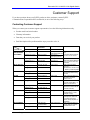
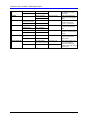
Dimension
GS-1116A and GS-1124A
Unmanaged 16 or 24 Port Gigabit Switch with 2 mini-GBIC Ports
User’s Guide
Version 1
10/2006
Edition 2
Dimension GS-1116A/GS-1124A Gigabit Switch
Copyright
Copyright © 2006 by ZyXEL Communications Corporation
The contents of this publication may not be reproduced in any part or as a whole, transcribed, stored
in a retrieval system, translated into any language, or transmitted in any form or by any means,
electronic, mechanical, magnetic, optical, chemical, photocopying, manual, or otherwise, without the
prior written permission of ZyXEL Communications Corporation.
Published by ZyXEL Communications Corporation. All rights reserved.
Disclaimer
ZyXEL does not assume any liability arising out of the application or use of any products, or software
described herein. Neither does it convey any license under its patent rights nor the patents rights of
others. ZyXEL further reserves the right to make changes in any products described herein without
notice. This publication is subject to change without notice.
Trademarks
Trademarks mentioned in this publication are used for identification purposes only and may be
properties of their respective owners.
ii
Copyright
Dimension GS-1116A/GS-1124A Gigabit Switch
ZyXEL Limited Warranty
ZyXEL warrants to the original end user (purchaser) that this product is free from any defects in
materials or workmanship for a period of up to two (2) years from the date of purchase. During the
warranty period and upon proof of purchase, should the product have indications of failure due to
faulty workmanship and/or materials, ZyXEL will, at its discretion, repair or replace the defective
products or components without charge for either parts or labor and to whatever extent it shall deem
necessary to restore the product or components to proper operating condition. Any replacement will
consist of a new or re-manufactured functionally equivalent product of equal value, and will be solely
at the discretion of ZyXEL. This warranty shall not apply if the product is modified, misused,
tampered with, damaged by an act of God, or subjected to abnormal working conditions.
Note
Repair or replacement, as provided under this warranty, is the exclusive remedy of the purchaser. This
warranty is in lieu of all other warranties, express or implied, including any implied warranty of
merchantability or fitness for a particular use or purpose. ZyXEL shall in no event be held liable for
indirect or consequential damages of any kind of character to the purchaser.
To obtain the services of this warranty, contact ZyXEL's Service Center for your Return Material
Authorization number (RMA). Products must be returned Postage Prepaid. It is recommended that the
unit be insured when shipped. Any returned products without proof of purchase or those with an outdated warranty will be repaired or replaced (at the discretion of ZyXEL) and the customer will be
billed for parts and labor. All repaired or replaced products will be shipped by ZyXEL to the
corresponding return address, Postage Paid. This warranty gives you specific legal rights, and you
may also have other rights that vary from country to country.
ZyXEL Limited Warranty
iii
Dimension GS-1116A/GS-1124A Gigabit Switch
Interference Statements and Warnings
FCC Interference Statement
This device complies with Part 15 of the FCC rules. Operation is subject to the following two
conditions:
(1) This device may not cause harmful interference.
(2) This device must accept any interference received, including interference that may cause
undesired operations.
FCC Warning
This equipment has been tested and found to comply with the limits for a Class A digital device,
pursuant to Part 15 of the FCC Rules. These limits are designed to provide reasonable protection
against harmful interference in a commercial environment. This equipment generates, uses, and can
radiate radio frequency energy and, if not installed and used in accordance with the instruction
manual, may cause harmful interference to radio communications. Operation of this equipment in a
residential area is likely to cause harmful interference in which case the user will be required to
correct the interference at his own expense.
CE Mark Warning
This is a class A product. In a domestic environment this product may cause radio interference in
which case the user may be required to take adequate measures.
Taiwanese BCIQ A Warning
Certifications
1. Go to www.zyxel.com
2. Select your product from the drop-down list box on the ZyXEL home page to go to that product's
page.
Select the certification you wish to view from this page.
iv
Interference Statements and Warnings
Dimension GS-1116A/GS-1124A Gigabit Switch
Customer Support
If you have questions about your ZyXEL product or desire assistance, contact ZyXEL
Communications Corporation offices worldwide, in one of the following ways:
Contacting Customer Support
When you contact your customer support representative, have the following information ready:
•
Product model and serial number
•
Warranty information
•
Date that you received your product.
•
Brief description of the problem and the steps you took to solve it.
METHOD SUPPORT E-MAIL
TELEPHONE
WEB SITE
FAX
FTP SITE
LOCATION
SALES E-MAIL
CORPORATE
HEADQUARTERS
(WORLDWIDE)
[email protected] +886-3-578-3942
COSTA RICA
CZECH REPUBLIC
DENMARK
FINLAND
FRANCE
[email protected]
+886-3-578-2439
[email protected]
+506-2017878
www.zyxel.com
www.europe.zyxel.com
ftp.zyxel.com
ftp.europe.zyxel.com
www.zyxel.co.cr
[email protected]
+506-2015098
ftp.zyxel.co.cr
[email protected]
+420-241-091-350
www.zyxel.cz
[email protected]
+420-241-091-359
[email protected]
+45-39-55-07-00
[email protected]
+45-39-55-07-07
[email protected]
+358-9-4780-8411
[email protected]
+358-9-4780 8448
[email protected]
+33-4-72-52-97-97
www.zyxel.dk
HUNGARY
KAZAKHSTAN
NORTH AMERICA
Customer Support
[email protected]
+49-2405-6909-0
[email protected]
+49-2405-6909-99
[email protected]
+36-1-3361649
[email protected]
+36-1-3259100
http://zyxel.kz/support +7-3272-590-698
ZyXEL Communications
Corp.
6 Innovation Road II Science
Park Hsinchu 300 Taiwan
ZyXEL Costa Rica
Plaza Roble Escazú Etapa El
Patio, Tercer Piso San José,
Costa Rica
ZyXEL Communications
Czech s.r.o.
Modranská 621 143 01 Praha
4 - Modrany Ceská Republika
ZyXEL Communications A/S
Columbusvej 2860 Soeborg
Denmark
www.zyxel.fi
ZyXEL Communications Oy
Malminkaari 10 00700
Helsinki Finland
www.zyxel.fr
ZyXEL France
1 rue des Vergers Bat. 1 / C
69760 Limonest France
ZyXEL Deutschland GmbH.
Adenauerstr. 20/A2 D-52146
Wuerselen Germany
+33-4-72-52-19-20
GERMANY
REGULAR MAIL
www.zyxel.de
www.zyxel.hu
www.zyxel.kz
[email protected]
+7-3272-590-689
[email protected]
1-800-255-4101
+1-714-632-0882
www.us.zyxel.com
[email protected]
+1-714-632-0858
ftp.us.zyxel.com
ZyXEL Hungary
48, Zoldlomb Str. H-1025,
Budapest Hungary
ZyXEL Kazakhstan
43, Dostyk ave.,Office 414
Dostyk Business Centre
050010, Almaty Republic of
Kazakhstan
ZyXEL Communications Inc.
1130 N. Miller St. Anaheim
CA 92806-2001 U.S.A.
v
Dimension GS-1116A/GS-1124A Gigabit Switch
NORWAY
POLAND
[email protected]
+47-22-80-61-80
[email protected]
+47-22-80-61-81
[email protected]
+48 (22) 333 8250
www.zyxel.no
ZyXEL Communications A/S
Nils Hansens vei 13 0667
Oslo Norway
www.pl.zyxel.com
ZyXEL Communications ul.
Okrzei 1A 03-715 Warszawa
Poland
www.zyxel.ru
ZyXEL Russia
Ostrovityanova 37a Str.
Moscow, 117279 Russia
www.zyxel.es
ZyXEL Communications Arte,
21 5ª planta 28033 Madrid
Spain
www.zyxel.se
ZyXEL Communications A/S
Sjöporten 4, 41764 Göteborg
Sweden
www.ua.zyxel.com
ZyXEL Ukraine
13, Pimonenko Str. Kiev,
04050 Ukraine
+48 (22) 333 8251
RUSSIA
SPAIN
SWEDEN
UKRAINE
UNITED KINGDOM
http://zyxel.ru/support
+7-095-542-89-29
[email protected]
+7-095-542-89-25
[email protected]
+34-902-195-420
[email protected]
+34-913-005-345
[email protected]
+46-31-744-7700
[email protected]
+46-31-744-7701
[email protected]
m
[email protected]
+380-44-247-69-78
[email protected]
[email protected]
vi
+380-44-494-49-32
+44-1344 303044
www.zyxel.co.uk
08707 555779 (UK only)
+44-1344 303034
ftp.zyxel.co.uk
ZyXEL Communications UK
Ltd.,11 The Courtyard,
Eastern Road, Bracknell,
Berkshire, RG12 2XB, United
Kingdom (UK)
Customer Support
Dimension GS-1116A/GS-1124A Gigabit Switch
Table of Contents
Chapter 1 Getting to Know the Switch.................................................................................................1-1
1.1
Introduction ........................................................................................................................................ 1-1
1.2
Features .............................................................................................................................................. 1-2
1.3
Package Contents ............................................................................................................................... 1-3
1.4
Gigabit Switch Network Applications................................................................................................ 1-3
Chapter 2 Hardware Description and Installation.................................................................................2-1
2.1
Desktop Installation............................................................................................................................ 2-1
2.2
Rack-mounted Installation.................................................................................................................. 2-2
2.3
Rear Panel .......................................................................................................................................... 2-3
2.4
Front Panel ......................................................................................................................................... 2-3
Chapter 3 Troubleshooting ...................................................................................................................3-1
3.1
Introduction ........................................................................................................................................ 3-1
3.2
Improper Network Cabling and Topology ......................................................................................... 3-2
Table of Contents
vii
Dimension GS-1116A/GS-1124A Gigabit Switch
List of Figures
Figure 1-1 GS-1116A ...........................................................................................................................1-1
Figure 1-2 GS-1124A ...........................................................................................................................1-1
Figure 1-3 Gigabit Switch for Server Farm ..........................................................................................1-4
Figure 1-4 Gigabit Switch for Super User Work Groups .....................................................................1-5
Figure 2-1 Attaching Rubber Feet ........................................................................................................2-1
Figure 2-2 Attaching Mounting Brackets and Screws..........................................................................2-2
Figure 2-3 Switch Mounting to an EIA Standard 19-inch Rack...........................................................2-2
Figure 2-4 Switch Rear Panel ...............................................................................................................2-3
Figure 2-5 GS-1116A Front Panel........................................................................................................2-3
Figure 2-6 GS-1124A Front Panel........................................................................................................2-3
Figure 2-7 Transceiver Installation Procedure......................................................................................2-5
Figure 2-8 Transceiver Removal Example ...........................................................................................2-6
Figure 2-11 GS-1116A Front Panel LEDs ...........................................................................................2-7
Figure 2-12 GS-1124A Front Panel LEDs ...........................................................................................2-7
List of Tables
Table 2-1 GS-1116A/GS-1124A: Front Panel Ports ............................................................................2-3
Table 2-2 Network Cable Types...........................................................................................................2-7
Table 2-3 Front Panel LED Descriptions .............................................................................................2-7
Table 3-1 Troubleshooting PWR LED .................................................................................................3-1
Table 3-2 Troubleshooting LNK/ACT LED ........................................................................................3-1
Table 3-3 Troubleshooting 1000 LEDs ................................................................................................3-1
Table 3-4 Troubleshooting Improper Network Cabling and Topology................................................3-2
List of Figures/Tables
ix
Dimension GS-1116A/GS-1124A Gigabit Switch
Preface
Congratulations on your purchase of the Dimension GS-1116A or GS-1124A unmanaged 16 or 24
port Gigabit switch with 2 mini-GBIC ports.
This preface introduces you to the Dimension GS-1116A and GS-1124A and discusses the
organization and conventions of this User’s Guide. It also provides information on other related
documentation.
About Gigabit Ethernet
Gigabit Ethernet is a 1Gbps (1000Mbps) extension of the IEEE 802.3 Ethernet networking standard.
Its primary applications are in corporate LANs, campus networks and service provider networks where
it can be used to tie together existing 100Mbps Ethernet networks.
About the Dimension GS-1116A and GS-1124A Gigabit Switch
The GS-1116A or GS-1124A is designed to improve your network performance with high-speed data
transmission over copper wire. The GS-1116A or GS-1124A provides an ideal upgrade path for
existing Ethernet-based networks that need more bandwidth. It can be installed as a backbone network
while retaining existing investments in Ethernet hubs, switches and wiring infrastructure.
General Syntax Conventions
For brevity’s sake, we will use “e.g.” as shorthand for “for instance”, and “i.e.” as shorthand for “that
is” or “in other words” throughout this manual.
The Dimension GS-1116A or GS-1124A unmanaged 16 or 24 port gigabit switch with 2 mini-GBIC
Ports may be referred to as “the switch” in this manual except where we refer to a specific switch.
Related Documentation
ZyXEL Web Site
The ZyXEL download library at www.zyxel.com contains additional support documentation and an
online glossary of networking terms.
x
Preface
Dimension GS-1116A/GS-1124A Gigabit Switch
Chapter 1
Getting to Know the Switch
This chapter describes the key features, benefits and applications of the switch.
1.1
Introduction
The switch is designed for the campus or building environment as a high bandwidth backbone. The
GS-1116A has 16 100/1000 Mbps RJ-45 ports. The GS-1124A has twenty-four 100/1000 Mbps RJ-45
ports. You can connect the switch to existing Ethernet routers, switches or hubs without additional
expensive wiring or equipment installation.
Figure 1-1 GS-1116A
Figure 1-2 GS-1124A
Gigabit Ethernet over copper technology is a cost effective way of upgrading network equipment
from fast Ethernet to Gigabit speed by using standard 4-pair Category 5 copper cabling. The Mini
GBIC slots allow for fiber optic high-speed backbone connections.
Both ports 15 and 16 in the GS-1116A (or 23 and 24 in the GS-1124A) support 3.3V Mini GBIC.
The GBIC port auto detects between Giga copper and Mini GBIC. The Mini GBIC module is
optional. When the Mini GBIC module is not installed, these act as Giga copper connections.
Getting to Know the GS1116A/GS-1124A
1-1
Dimension GS-1116A/GS-1124A Gigabit Switch
The switch is an ideal solution for solving traffic block at the core of the network. It offers autonegotiation 100/1000Base-T Gigabit Ethernet ports that can significantly improve your network
backbone performance.
1.2
Features
•
Conforms to IEEE 802.3 10Base-T, IEEE 802.3u 100Base-TX, IEEE 802.3z Gigabit fiber and
IEEE 802.3ab 1000Base-T standards.
•
IEEE 802.1p supports two priority queues for outgoing traffic helping improving network
efficiency and performance.
•
Auto-negotiating 100/1000Mbps Ethernet RJ-45 ports.
•
Automatic MDI/MDIX supported.
•
Switching fabric of 32Gbps in the GS-1116A and 48Gbps in the GS-1124A.
•
N-way Auto-negotiation supported.
•
Embedded 8K MAC address table providing 8000 MAC address entries.
•
Two 3.3V Mini GBIC ports for Gigabit fiber transceiver.
•
Two Gigabit copper ports.
•
Supports auto address learning.
•
Supports store-and-forwarding switching architecture for abnormal packet filtering.
•
Back-Pressure-Base flow control on Half-duplex mode Ethernet ports.
•
Pause-Frame-Base flow control on Full-duplex mode Ethernet ports.
•
No-Blocking full wire speed architecture.
•
One fan for good ventilation and to increase system heat sink performance.
•
Power, 1000 and LNK/ACT LEDs.
•
Standard 19-inch rack mount design
1.2.1 IEEE 802.1p Class of Service
The IEEE 802.1p Class of Service (CoS) provides two queues for high and low priority traffic. This
improves network efficiency and performance by giving higher priority to outgoing traffic. The lower
queue has a priority value in the range of zero to three and the higher queue has a priority value in the
range of four to seven.
)
When the Mini GBIC module is installed, the Mini GBIC (Giga fiber) port
has higher priority than Giga copper port. When the Mini GBIC port is
connected, the Giga copper port is disabled.
1-2
Getting to Know the GS1116A/GS-1124A
Dimension GS-1116A/GS-1124A Gigabit Switch
1.3
Package Contents
Compare the contents of your GS-1116A/GS-1124A Gigabit Switch package with the checklist
below. If any item is missing or damaged, please contact your local dealer.
•
GS-1116A or GS-1124A Gigabit switch
•
Power cord
•
Quick Start Guide
•
This User’s Guide in CD-ROM format.
•
Four rubber feet
•
Rack mount brackets
1.4
Gigabit Switch Network Applications
This section provides a sample of network topologies in which the Gigabit switch functions as a highbandwidth backbone switch for a server farm or as a high-bandwidth backbone switch for a super user
workgroup. The switch is an ideal upgrade for 100Mbps Ethernet networks. You can connect existing
switches, hubs or computers with Gigabit 1000Base-T Ethernet adapters to the switch.
1.4.1 Gigabit Switch for Server Farm
The following figure depicts the GS-1124A (Z) connected to a computer network (via switches A, B
and C) and a server farm (via Gigabit switch G). For enterprise networks where large data broadcasts
are constantly processed, this switch is suitable for connecting departmental switches to the core
Gigabit switch through a number of servers. Connecting servers to the core Gigabit switch allows
each end station to rapidly access the server’s data and to smoothly communicate with all the devices
in the network.
Getting to Know the GS1116A/GS-1124A
1-3
Dimension GS-1116A/GS-1124A Gigabit Switch
Figure 1-3 Gigabit Switch for Server Farm
1.4.2 Gigabit Switch for “Super User” Work Groups
You can use the GS-1116A or the GS-1124A to connect servers, switches, workstations and
computers (the Gigabit 1000Base-T NIC must be installed onto the computer) to each other.
The following figure depicts a typical backbone application of the switch in an enterprise
environment. The “Normal User” workgroup (A, B, C) is connected to a switch via a 10/100Mbps
and the “Super User” workgroup (D, E, F) is connected to a Gigabit switch (G). This enables the two
networks to communicate with each other, prioritizing the “Super User” network with higher
connection speeds though a Gigabit switch.
The “Normal User” workgroup runs applications that are not time sensitive and do not require large
amounts of bandwidth, such as Internet browsing and e-mail.
The “Super User” workgroup runs bandwidth-hungry applications like large FTP file transfers and
real time applications such as video conferencing.
The switch automatically learns node addresses, which are subsequently used to filter and forward all
traffic based on the destination address. You can use the Mini GBIC slots to connect with a fiber optic
1-4
Getting to Know the GS1116A/GS-1124A
Dimension GS-1116A/GS-1124A Gigabit Switch
network that extends your Ethernet network and to separate “Normal User” and “Super User”
networks.
Figure 1-4 Gigabit Switch for Super User Work Groups
Getting to Know the GS1116A/GS-1124A
1-5
Dimension GS-1116A/GS-1124A Gigabit Switch
Chapter 2
Hardware Description and Installation
This section discusses switch installations, hardware and functional overview.
The switch is suited to an office environment where it can be rack mounted on standard EIA racks or
placed as a standalone switch on a desktop.
)
For proper ventilation, allow at least 4 inches (10 cm) of clearance at
the front, 3.4 inches (8 cm) at the back of the switch. This is especially
important for enclosed rack installations.
2.1
Desktop Installation
1. Set the switch upside-down on a study level space with a power outlet nearby.
2. Make sure there is enough clearance around the switch to allow air circulation and the attachment
of cables and the power cord.
3. Remove the adhesive backing from the supplied rubber feet.
4. Attach the rubber feet to each corner on the bottom of the switch. These rubber feet help protect
the switch from shock or vibration and ensure space between devices when stacking.
5. Turn the switch right side up after you attach the rubber feet.
Figure 2-1 Attaching Rubber Feet
)
Do not block the ventilation holes. Leave space between switches
when stacking.
Hardware Description and Installation
2-1
Dimension GS-1116A/GS-1124A Gigabit Switch
2.2
Rack-mounted Installation
The switch can be mounted on an EIA standard size, 19-inch rack or in a wiring closet with other
equipment. Follow the steps below to mount your switch on a standard EIA rack using the included
rack-mounting kit.
1. Align one bracket with the holes on one side of the switch and secure it with the bracket screws.
Similarly, attach the other bracket.
Figure 2-2 Attaching Mounting Brackets and Screws
2. After attaching both mounting brackets, position the switch in the rack by lining up the holes in the
brackets with the appropriate holes on the rack. Secure the switch to the rack with the rack’s
mounting screws.
Figure 2-3 Switch Mounting to an EIA Standard 19-inch Rack
2-2
Hardware Description and Installation
Dimension GS-1116A/GS-1124A Gigabit Switch
2.3
Rear Panel
The ventilation fan and three-pronged power receptacle are located on the rear panel of the switch.
Figure 2-4 Switch Rear Panel
2.3.1 Rear Panel Power Connection
Connect one end of the supplied power cord to the power receptacle on the back of the switch and the
other end to the 100-240 VAC, 50-60 Hz power source. Push the power switch to the ON position.
2.4
Front Panel
The following graphics show the front panels of the GS-1116A and the GS-1124A.
Figure 2-5 GS-1116A Front Panel
Figure 2-6 GS-1124A Front Panel
Table 2-1 GS-1116A/GS-1124A: Front Panel Ports
CONNECTOR
DESCRIPTION
RJ-45 ports
Connect these 100/1000 Mbps RJ-45 Ethernet ports to computers, hubs, Ethernet
switches or routers.
Mini GBIC ports
Use mini GBIC transceivers in these ports for fiber-optical connections to
backbone Ethernet switches.
2.4.1 100/1000Mbps RJ-45 Auto-negotiating Ports
The GS-1116A has 16 100/1000 Mbps RJ-45 ports. The GS-1124A has twenty-four 100/1000 Mbps
RJ-45 ports. The auto-negotiation feature allows the switches to detect the speed of incoming
transmission and adjust appropriately without manual intervention. It allows data transfers of either
•
100Mbps in half-duplex mode
Hardware Description and Installation
2-3
Dimension GS-1116A/GS-1124A Gigabit Switch
•
100Mbps or 1000Mbps in full-duplex mode depending on your Ethernet network.
2.4.2 Auto-sensing (Auto MDI/MDIX) Ports
You can connect each RJ-45 auto-sensing port to a computer, hub or switch using either a straight
through or a crossover Ethernet cable.
2.4.3 Mini GBIC Slots
These are slots for Mini GBIC (Gigabit Interface Converter) transceivers. A transceiver is a single
unit that houses a transmitter and a receiver. The switch does not come with transceivers. You must
use transceivers that comply with the Small Form-factor Pluggable (SFP) Transceiver MultiSource
Agreement (MSA). See the SFF committee’s INF-8074i specification Rev 1.0 for details.
You can change transceivers while the switch is operating. You can use different transceivers to
connect to Ethernet switches with different types of fiber-optic connectors.
)
To avoid possible eye injury, do not look into an operating fiber-optic
module’s connectors.
•
Type: SFP connection interface
•
Connection speed: 1 gigabit per second (Gbps)
Transceiver Installation
Use the following steps to install a mini GBIC transceiver (SFP module).
1. Insert the transceiver into the slot with the exposed section of PCB board facing down.
2. Press the transceiver firmly until it clicks into place.
3. The switch automatically detects the installed transceiver. Check the LEDs to verify that it is
functioning properly.
2-4
Hardware Description and Installation
Dimension GS-1116A/GS-1124A Gigabit Switch
Figure 2-7 Transceiver Installation Procedure
Transceiver Removal
Use the following steps to remove a mini GBIC transceiver (SFP module) from the GBIC port.
1. Remove the fiber-optic cables from the transceiver.
2. Unlock the transceiver’s latch (latch styles vary).
3. Pull the transceiver out of the slot.
4. Put the transceiver’s dust cover on the transceiver.
Hardware Description and Installation
2-5
Dimension GS-1116A/GS-1124A Gigabit Switch
Figure 2-8 Transceiver Removal Example
)
Keep the dust cover on a fiber optic module until you connect it.
Use the appropriate Ethernet or fiber-optic cables to connect the module to an Ethernet switch. With a
fiber-optic module, remove the dust covers from the connectors. You may need to clean the fiberoptic cable’s connectors with a cotton swab dipped in alcohol.
2.4.4 Front Panel Connections
You can use unshielded twisted pair (UTP) or shielded twisted-pair (STP) Ethernet cables for RJ-45
ports. The following table describes the types of network cable used for the different connection
speeds.
2-6
Hardware Description and Installation
Dimension GS-1116A/GS-1124A Gigabit Switch
Table 2-2 Network Cable Types
SPEED
NETWORK CABLE TYPE
100Mbps
100Ω 2-pair UTP/STP Category 5
1000Mbps
100Ω 4-pair UTP/STP Category 5
)
Make sure the cable length between connections does not exceed 100
meters (328 feet).
2.4.5 Front Panel LEDs
The LEDs give real-time status information.
Figure 2-9 GS-1116A Front Panel LEDs
Figure 2-10 GS-1124A Front Panel LEDs
The following table provides LED descriptions.
Table 2-3 Front Panel LED Descriptions
SYSTEM
LED
PWR
1000
LNK/ACT
COLOR
Green
Green
Green
STATUS
DESCRIPTION
On
The switch is turned on and receiving power.
Off
The switch is off or not receiving power.
On
A link to a 1000Mbps Ethernet device is up.
Blinking
A link to a 1000Mbps Ethernet device is up, and the port is
receiving or transmitting data.
Off
The port is not connected to a 1000Mbps Ethernet device.
On
The port is connected to a 10/100Mbps Ethernet device.
Blinking
Off
Hardware Description and Installation
A link to a 10/100Mbps Ethernet Device is up, and the port is
receiving or transmitting data.
The port is not connected to a 10/100Mbps device.
2-7
Dimension GS-1116A/GS-1124A Gigabit Switch
Chapter 3
Troubleshooting
This section describes common problems you may encounter with the switch in your network and
possible solutions.
3.1
Introduction
Troubleshoot the switch using the LEDs to detect problems.
3.1.1 PWR LED
The PWR LED on the front panel does not light up.
Table 3-1 Troubleshooting PWR LED
STEPS
CORRECTIVE ACTION
1
Check the connections from your switch to the power source. Make sure you are using the supplied
power cord and that you are using a 100 - 240V AC, 50/60Hz power source.
2
Make sure the power source is turned on and that the switch is receiving sufficient power.
3
If these steps fail to correct the problem, contact your local distributor for assistance.
3.1.2 LNK/ACT LED
The LNK/ACT LED does not light up when a device is connected.
Table 3-2 Troubleshooting LNK/ACT LED
STEPS
CORRECTIVE ACTION
1
Verify that the attached device(s) is turned on and properly connected to your switch.
2
Make sure the Ethernet adapters are working on the attached devices.
3
Verify that proper network cable type is used and its length does not exceed 100 meters. For more
information on network cable types, see Table 2-2.
3.1.3 1000 LED
The LEDs do not show the speed of my Ethernet device.
Table 3-3 Troubleshooting 1000 LEDs
STEPS
CORRECTIVE ACTION
1
Check the connection between the switch and your Ethernet device(s).
2
Verify that you are using the proper cable type and that its length does not exceed 100 meters. For
more information on network cable types, see Table 2-2.
Troubleshooting
3-1
Dimension GS-1116A/GS-1124A Gigabit Switch
3.2
Improper Network Cabling and Topology
Improper network cabling or topology setup is a common cause of poor network performance and
network failure.
Table 3-4 Troubleshooting Improper Network Cabling and Topology
DESCRIPTION
Faulty cables
PROBLEMS AND CORRECTIVE ACTION
Using faulty network cables may affect data rates and have an impact on your network
performance. Replace with new standard network cables.
Non-standard network Non-standard cables may increase the number of packet collisions and cause other
cables
network problems that affect your network performance. Refer to Table 2-2 for more
information on network cable types.
Cabling Length
If you use longer cables than are needed, transmission quality may be affected.
The network cables should not be longer than the limit of 100 meters.
Too many hubs
Too many hubs (or repeaters) between the connected computers in the network may
between the computers increase the number of packet collisions or other network problems. Remove
in the network
unnecessary hubs from the network.
A loop in the data path A data path loop forms when there is more than one path or route between two
networked computers. This results in broadcast storms that will severely affect your
network performance. Make sure there are no loops in your network topology.
3-2
Troubleshooting
Dimension GS-1116A/GS-1124A Gigabit Switch
Product Specifications
This section provides the specifications of the switch.
GENERAL
IEEE 802.3 10BASE-T Ethernet
IEEE 802.3u 100BASE-TX Fast Ethernet
Standards
IEEE 802.3ab 1000Base-T
IEEE 802.3z Gigabit Fiber
IEEE 802.1p Class of Service
GS-1116A: 14x 1000Base-T Ethernet Ports
GS-1124A: 22x 1000Base-T Ethernet Ports
Subscriber Interface
¾ Connector type: RJ-45
¾ Auto-MDIX
¾ Compliant with IEEE 802.3/3u
¾ Back pressure flow control for half duplex
¾ Flow control for full duplex (IEEE 802.3x)
Uplink Interface
2 GbE Dual Personality interface (Each dual personality has one 1000Base-T
copper port and one Small Form-Factor Pluggable (SFP) fiber port, with one
port active at a time.)
Media Interface Exchange
All ports auto-sensing (auto MDI-/MDI-X)
Data Transfer Rate
Fast Ethernet: 100Mbps (half duplex)/200Mbps (full duplex)
Gigabit Ethernet: 2000Mbps(full duplex)
10BASE-T: 2-pair UTP/STP Cat. 3, 4, 5 cable
EIA/TIA-568 100-ohm (100m)
Network Cables
100BASE-TX: 2-pair UTP/STP CAT. 5 cable
EIA/TIA-568 100-ohm (100m)
Gigabit Copper: 4 pair UTP/STP CAT. 5 cable
EIA/TIA 568 100-ohm (100M)
Performance and Management
Packet Forwarding Rate
Switching Method
MAC Address Table (Autolearning)
Data Buffer
Product Specifications
148800PPS for 100BASE-TX
1488000PPS for 1000BASE-T
Store-and-Forward switching architecture
GS-1116A: 8K entries
GS-1124A: 8K entries
GS-1116A: 340KB
GS-1124A: 500 KB
A
Dimension GS-1116A/GS-1124A Gigabit Switch
GS-1116A Switching fabric: 32Gbps. GS-1124A Switching fabric: 48Gbps
GS-1116A Memory Buffer: 340KB GS-1124A Memory Buffer: 500KB
Support Frame size: 1522 bytes
Layer 2 features
8K MAC addresses table
Jumbo frame support: Support 9Kbytes Jumbo frame size
CoS: Support 802.1p provided Tag based priority and per port 4 queues
Broadcast storm control
Physical Environment
Power (green): Light on or off: Power on or off
1000Base-T Ethernet ports:
z 1000M green LED
¾Light off: port is not connected at 1000M
LED
¾Light on: port is connected at 1000M
¾Blinking: activity
z LNK/ACT: Green LED
¾Light off: port disconnected
¾Light on: port connected at 10M, 100M or 1000M
¾Blinking: activity
Power Supply
Power Consumption
100 - 240V AC, 50/60Hz internal universal power supply
GS-1116A: 13.25 W max
GS-1124A: 23.2 W max
Operating Temperature
0ºC to 45ºC (32ºF to 113ºF)
Operational Humidity
10% to 90% (Non-condensing)
EMI
FCC Class A, CE
B
Product Specifications
Dimension GS-1116A/GS-1124A Gigabit Switch
Index
1000/ 100 Ethernet LED .............................. 2-4
802.3x .......................................................... 1-2
About the Dimension Gigabit Switch............. x
Installation
Desktop ....................................................2-1
Network Application
Auto MDI/MDIX......................................... 2-4
Backbone Switch......................................1-3
Auto-negotiation .......................................... 2-3
Network Cable Length Limit .......................2-7
Cabling Length ............................................ 3-2
Network Cable Types...................................2-7
Campus Environment .................................. 1-1
1000Mbps ................................................2-7
CE .................................................................. iv
100Mbps ..................................................2-7
Certification ................................................... iv
Non-standard network cables.......................3-2
class A............................................................ iv
Normal User workgroup ..............................1-4
Collisions ..................................................... 2-8
Package Contents .........................................1-3
Contacting Customer Support......................... v
Power Connection ........................................2-3
Copyright ........................................................ ii
Power Receptacle.........................................2-3
CoS .............................................................. 1-2
Product Specifications
Data path loop.............................................. 3-2
General ....................................................... A
Desktop Installation ..................................... 2-1
Performance and Management................... A
Disclaimer....................................................... ii
Physical Environment ................................ A
Faulty cables ................................................ 3-2
Rack-mounted Installation ...........................2-2
FCC................................................................ iv
Rear Panel ....................................................2-3
FCC Rules...................................................... iv
Related Documentation................................... x
Features........................................................ 1-2
Repair.............................................................iii
Federal Communications Commission (FCC)
Interference Statement ............................... iv
Return Material Authorization number..........iii
Front Panel................................................... 2-3
Front Panel Connections.............................. 2-6
Front Panel LED .......................................... 2-7
Front Panel LED Descriptions..................... 2-8
GBIC............................................................ 2-4
Gigabit Ethernet.............................................. x
High Bandwidth Backbone.......................... 1-1
IEEE 802.1p................................................. 1-2
Installation
Rack-Mounted ......................................... 2-2
Index
RJ-45 ports ...................................................2-3
Server Farm..................................................1-3
Service............................................................iii
Speed............................................................3-1
Store-and-Forward Switching ......................1-2
Super User workgroup .................................1-4
Syntax Conventions ........................................ x
Trademarks .....................................................ii
Transceiver...................................................1-2
Transceiver Installation................................2-4
Transceiver Removal ...................................2-5
C
Dimension GS-1116A/GS-1124A Gigabit Switch
Troubleshooting
1000 LEDs ...............................................3-1
Troubleshooting
Ventilation Fan............................................ 2-3
Warranty........................................................ iii
LK/ACT LED ..........................................3-1
Work Groups............................................... 1-4
PWR LED ................................................3-1
ZyXEL Limited Warranty ............................. iii
Troubleshooting
Network Cabling and Topology...............3-2
D
ventilation.................................................... 2-1
Note ........................................................... iii
ZyXEL Web Site.............................................x
Index