1
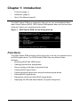
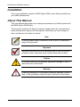
RAID OPTION ROM
USER MANUAL
Version 1.6
RAID Option ROM User Manual
Copyright
© 2008 Advanced Micro Devices, Inc. All Rights Reserved.
Copyright by Advanced Micro Devices, Inc. (AMD). No part of this manual may
be reproduced or transmitted in any form without the expressed, written
permission of AMD.
Trademarks
AMD and the AMD logo are registered in U.S. Patent and Trademark Office. All
other product names mentioned herein may be trademarks or registered
trademarks of their respective companies.
Important data protection information
You should back up all data before installing any drive controller or storage
peripheral. AMD is not responsible for any loss of data resulting from the use,
disuse or misuse of this or any other AMD product.
Notice
Although AMD has attempted to ensure the accuracy of the content of this
manual, it is possible that this document may contain technical inaccuracies,
typographical, or other errors. AMD assumes no liability for any error in this
publication, and for damages, whether direct, indirect, incidental, consequential
or otherwise, that may result from such error, including, but not limited to loss of
data or profits.
AMD provides this publication “as is” without warranty of any kind, either express
or implied, including, but not limited to implied warranties of merchantability or
fitness for a particular purpose.
The published information in the manual is subject to change without notice.
AMD reserves the right to make changes in the product design, layout, and driver
revisions without notification to its users.
This version of the User Manual supersedes all previous versions.
Recommendations
In this User Manual, the appearance of products made by other companies,
including, but not limited to software, servers, and physical drives, is for the
purpose of illustration and explanation only. AMD does not recommend, endorse,
prefer or support any product made by another manufacturer.
ii
Contents
Chapter 1: Introduction . . . . . . . . . . . . . . . . . . . . . . . . . . . . . . . . . . . . .1
Functions . . . . . . . . . . . . . . . . . . . . . . . . . . . . . . . . . . . . . . . . . . . . . .1
Installation . . . . . . . . . . . . . . . . . . . . . . . . . . . . . . . . . . . . . . . . . . . . .2
About This Manual . . . . . . . . . . . . . . . . . . . . . . . . . . . . . . . . . . . . . . .2
Chapter 2: Using RAID Option ROM . . . . . . . . . . . . . . . . . . . . . . . . . .3
Opening RAID Option ROM . . . . . . . . . . . . . . . . . . . . . . . . . . . . . . .3
Using the Main Menu . . . . . . . . . . . . . . . . . . . . . . . . . . . . . . . . . . . . .4
Viewing Drive Assignments . . . . . . . . . . . . . . . . . . . . . . . . . . . . . . . .5
Secure Erasing a Physical Drive . . . . . . . . . . . . . . . . . . . . . . . . . . . .6
Creating a Logical Drive . . . . . . . . . . . . . . . . . . . . . . . . . . . . . . . . . .9
One Logical Drive . . . . . . . . . . . . . . . . . . . . . . . . . . . . . . . . . . .11
Two Logical Drives . . . . . . . . . . . . . . . . . . . . . . . . . . . . . . . . . .11
Viewing Drive Assignments, Split Physical Drives . . . . . . . . . .13
Deleting a Logical Drive . . . . . . . . . . . . . . . . . . . . . . . . . . . . . . . . . .14
Viewing Controller Configuration . . . . . . . . . . . . . . . . . . . . . . . . . . .15
System Resources . . . . . . . . . . . . . . . . . . . . . . . . . . . . . . . . . .15
Responding to Logical Drive Problems . . . . . . . . . . . . . . . . . . . . . .16
Chapter 3: Technology Background . . . . . . . . . . . . . . . . . . . . . . . . .17
Introduction to RAID . . . . . . . . . . . . . . . . . . . . . . . . . . . . . . . . . . . .17
RAID 0 – Stripe . . . . . . . . . . . . . . . . . . . . . . . . . . . . . . . . . . . . .18
RAID 1 – Mirror . . . . . . . . . . . . . . . . . . . . . . . . . . . . . . . . . . . . .19
RAID 5 – Block Striping with Distributed Parity . . . . . . . . . . . . .20
RAID 10 – Mirror/Stripe . . . . . . . . . . . . . . . . . . . . . . . . . . . . . .21
RAID Ready – Single Drive . . . . . . . . . . . . . . . . . . . . . . . . . . . .22
JBOD . . . . . . . . . . . . . . . . . . . . . . . . . . . . . . . . . . . . . . . . . . . .23
Choosing a RAID Level . . . . . . . . . . . . . . . . . . . . . . . . . . . . . . . . . .24
RAID 0 . . . . . . . . . . . . . . . . . . . . . . . . . . . . . . . . . . . . . . . . . . .24
RAID 1 . . . . . . . . . . . . . . . . . . . . . . . . . . . . . . . . . . . . . . . . . . .24
RAID 5 . . . . . . . . . . . . . . . . . . . . . . . . . . . . . . . . . . . . . . . . . . .25
RAID 10 . . . . . . . . . . . . . . . . . . . . . . . . . . . . . . . . . . . . . . . . . .25
RAID Ready . . . . . . . . . . . . . . . . . . . . . . . . . . . . . . . . . . . . . . .25
JBOD . . . . . . . . . . . . . . . . . . . . . . . . . . . . . . . . . . . . . . . . . . . .26
Stripe Block Size . . . . . . . . . . . . . . . . . . . . . . . . . . . . . . . . . . . . . . .27
Gigabyte Boundary . . . . . . . . . . . . . . . . . . . . . . . . . . . . . . . . . . . . .27
Initialization . . . . . . . . . . . . . . . . . . . . . . . . . . . . . . . . . . . . . . . . . . .27
Partition and Format the Logical Drive . . . . . . . . . . . . . . . . . . . . . .28
Appendix A: Partition and Format . . . . . . . . . . . . . . . . . . . . . . . . . . .29
iii
RAID Option ROM User Manual
iv
Chapter 1: Introduction
•
Functions (page 1)
•
Installation (page 2)
•
About This Manual (page 2)
The RAID Option ROM is an application that runs on your motherboard’s Basic
Input Output System (BIOS). RAID Option ROM appears when you first boot your
computer, before your operating system loads.
Figure 1. RAID Option ROM screen during boot-up
Functions
The RAID Option ROM includes a Utility with tools to set up your physical drives
as RAID logical drives. The RAID Option ROM Utility can perform these
functions:
•
Monitoring RAID and JBOD status
•
Viewing physical drive assignments
•
Secure erasing of all data on physical drives
•
Creating RAID logical drives
•
Creating multiple logical drives using the same physical drives
•
Deleting RAID logical drives
•
Diagnosing critical and offline RAID logical drives
•
Displaying the IRQ and base address (for system diagnosis)
1
RAID Option ROM User Manual
Installation
There is no installation required. RAID Option ROM comes factory-installed on
your AMD motherboard.
About This Manual
This User Manual describes how to setup and maintain your RAID system with
the RAID Option ROM Utility.
This manual includes a full table of contents, chapter task lists, and numerous
cross-references to help you find the specific information you are looking for.
Also included are four levels of notices:
Note
A Note provides helpful information such as hints or alternative
ways of doing a task.
Important
Important calls attention to an essential step or point required to
complete a task. Important items include things often missed.
Caution
A Caution informs you of possible equipment damage or loss of
data and how to avoid them.
Warning
A Warning notifies you of probable equipment damage or loss of
data, or the possibility of physical injury, and how to avoid them.
2
Chapter 2: Using RAID Option ROM
•
Opening RAID Option ROM
(below)
•
Creating a Logical Drive (page 9)
•
Deleting a Logical Drive (page 14)
•
Using the Main Menu (page 4)
•
•
Viewing Drive Assignments
(page 5)
Viewing Controller Configuration
(page 15)
•
•
Secure Erasing a Physical Drive
(page 6)
Responding to Logical Drive
Problems (page 16)
Opening RAID Option ROM
The RAID Option ROM and the RAID Option ROM Utility are built-in components
of the AMD motherboard.
When the RAID Option ROM loads during boot-up, it displays pertinent
information about the RAID logical drives that it finds.
When the RAID Option ROM screen appears, press Ctrl-F to enter the Utility. The
RAID Option ROM screen displays the following information:
•
ID – An identification number assigned to each logical drive by the Option
ROM.
•
Mode – The RAID mode (level) configuration of the logical drive
•
Size – The data capacity of the logical drive in GB (Gigabytes).
•
Track-Mapping – This is the CHS (Cylinder/Head/Sector) equivalent of the
logical drive geometry as hosted by the RAID Option ROM int 13h disk
services.
3
RAID Option ROM User Manual
•
Status – Shows one of three logical drive conditions:
•
Functional – The logical drive is fully operational, and no problems are
present.
•
Critical – The logical drive is still operational, meaning you can read
and write data to it. But the logical drive has lost fault tolerance.
For RAID levels 1, 5, and 10, the logical drive contains a failed physical
drive. You must identify and replace the failed physical drive, then
rebuild the logical drive using the RAIDXpert software.
•
Offline – The logical drive is no longer operational, meaning you cannot
read and write data to it. You must identify and replace the failed
drive(s). Then you can create a new logical drive and copy your data to
it from the last tape backup or other device.
For RAID levels 1, 5, and 10, two or more physical drives in the logical
drive have failed.
For a RAID 0 or JBOD at least one physical drive has failed.
A RAID Ready logical drive disappears from the user interface when its
physical drive fails.
•
Port – The port number to which the Single Disk (unassigned physical drive)
is attached.
•
Device Name – The manufacturer’s name and model number of this
physical drive.
Using the Main Menu
When the RAID Option ROM displays on your computer screen, press Ctrl-F to
enter the Utility and display the Main Menu.
4
Chapter 2: Using RAID Option ROM
The Main Menu (above) has five options:
•
Press 1 to view physical drive assignments
•
Press 2 to create a logical drive or view information about an existing logical
drive.
•
Press 3 to delete a logical drive.
•
Press 4 to view the controller configuration.
•
Press Esc (Escape) to exit the utility.
Viewing Drive Assignments
From the Main Menu screen, press 1 to see the View Drive Assignments screen
(below).
This screen reports physical drive assignments and provides the following
information:
•
Channel: ID – Shows the AMD motherboard channel ID (1 through 4) to
which a particular physical drive is attached.
•
Drive Model – Identifies the manufacturer, model, and model number (if
applicable) of each physical drive.
•
Capabilities – The type and speed of the physical drive, such as SATA
1.5 Gb/s or 3.0 Gb/s
•
Capacity (GB) – Reflects the capacity in GB (gigabytes) of the physical
drive.
•
Assignment – This field identifies the logical drive to which the physical
drive belongs. In the example above, there is one logical drive composed of
two physical drives. LD 1-2 means logical drive 1, physical drive 2.
Unassigned drives are labeled Single Disk. You can use unassigned drives
to create a new logical drive.
5
RAID Option ROM User Manual
•
Extent – An extent is a portion of the physical drive. The RAID Option ROM
Utility allows you to split the capacity of a physical drive between two logical
drives. The portion of a physical drive available to be used in a logical drive
is called an extent. The sum of the two extents is slightly smaller than the
total capacity of the physical drive.
See “Viewing Drive Assignments, Split Physical Drives” on page 13 for an
example of two extents for each physical drive.
Secure Erasing a Physical Drive
Warnings
•
When you secure erase a physical drive, you permanently
delete all data on the physical drive. There is no way to
restore your data after a secure erase.
•
Do not secure erase a physical drive that belongs to a logical
drive. This action will cause the logical drive to go Critical or
Offline.
•
Backup any important data before you use this feature!
Important
Once you begin, you cannot exit the RAID Option ROM Utility until
the Secure Erase operation is finished. Secure Erase takes about
the same amount of time as a partition and format. Plan ahead
and allow yourself enough time.
The Secure Erase feature overwrites all sectors on a physical drive.
6
Chapter 2: Using RAID Option ROM
To secure erase a physical drive:
1.
From the Main Menu screen, press 1 to see the View Drive Assignments
screen (below).
2.
Press the arrow keys to highlight a physical drive you want to secure erase
and press Ctrl-H.
The caution screen appears.
3.
Press Y to continue.
The settings screen appears.
4.
5.
Optional. Press the arrow keys to highlight the settings you want. Press the
Backspace key to delete, then enter a new value for:
•
Erase Count. The default is 1.
•
Erase Pattern The default is 55AA (hexadecimal)
Press Ctrl-E to continue.
7
RAID Option ROM User Manual
The confirmation screen displays.
6.
Press Ctrl-P to secure erase your physical drive.
Watch the screen to monitor the progress.
Secure Erase runs until all sectors of the selected physical drive have been
overwritten. Depending on the size of your physical drive, this operation can
take some time. You cannot exit the RAID Option ROM Utility until the
Secure Erase is done.
8
Chapter 2: Using RAID Option ROM
Creating a Logical Drive
1.
From the Main Menu screen, press 2 to display the Define LD Menu (below).
2.
Press the arrow keys to highlight a logical drive number you want to define
and press Enter to select it.
The Define LD Menu appears for the number you selected (below).
3.
Choose the RAID Level you want. In the Define LD Menu section, press the
Spacebar to toggle through logical drive types:
•
RAID 0 (Stripe)
•
RAID 1 (Mirror)
•
RAID 5 (Stripe with Distributed Parity)
•
RAID 10 (Stripe / Mirror)
•
RAID Ready (Single Drive)
•
JBOD (Just a Bunch of Disks)
9
RAID Option ROM User Manual
See “Choosing a RAID Level” on page 24 for more information.
4.
5.
Press the arrow keys to move to the next option. Option choices depend on
the RAID level you selected.
•
Fast Init erases the Master Boot Record (MBR) of the physical drives
when this feature is set to ON. For more information, see page 27.
•
Stripe Block Size. Press the Spacebar to toggle between 64 KB and
128 KB. For more information, see page 27.
•
Gigabyte Boundary. Press the Spacebar to toggle between ON and
OFF. For more information, see page 27.
•
Cache Mode. Only WriteThru is available.
Press the arrow keys to move to Disk Assignments. Press the spacebar to
toggle between N and Y for each available drive. Y means this physical drive
will be assigned to the logical drive.
Assign the appropriate number of physical drives to your logical drive. See
“Choosing a RAID Level” on page 24 for more information.
6.
7.
Choose your Initialization option. See “Initialization” on page 27 for more
information.
•
For Fast initialization, set Fast Init to ON. This option is preferred.
•
For No initialization, set Fast Init to OFF.
Press Ctrl-Y to save your logical drive configuration.
If you set Fast Init to ON, the following message displays:
Press Ctrl-Y to perform the fast initialization. Press any other key to skip
initialization.
You have the option of using all of the physical drive capacity for one logical
drive or allocating a portion to a second logical drive.
This option is not available for JBOD or RAID Ready logical drives.
8.
Choose one of the following:
•
Allocate the full capacity of the physical drives to a single logical drive.
Go to “One Logical Drive” on page 11.
•
Split the capacity of the physical drives between two logical drives. Go
to “Two Logical Drives” on page 11.
10
Chapter 2: Using RAID Option ROM
One Logical Drive
Continued from Create Logical Drive step 8, above.
1.
Press any key (except for Ctrl-Y) to use the full portion of the logical drive for
one logical drive.
2.
Press Esc to exit to the Main Menu. Press Esc again to exit the Utility.
3.
Press Y to restart the computer.
You have successfully created a new RAID logical drive.
Note
You must be partition and format your new logical drive before you
can use it. See “Appendix A: Partition and Format” on page 29.
Two Logical Drives
Continued from Create Logical Drive step 8, above.
1.
Press Ctrl-Y to allocate a portion of the physical drives to the first logical
drive.
2.
Enter the desired capacity in GB for the first logical drive and press Enter.
11
RAID Option ROM User Manual
The Define LD Menu displays again.
3.
Press the up and down arrow keys to select an available logical drive
number and press Enter.
4.
Choose the RAID level and options for the second logical drive.
Note that the physical drives in Channels 1, 2, and 3 reflect smaller
capacities because a portion of their original capacity belongs to a different
logical drive.
The physical drive in Channel 4 is not yet assigned to a logical drive, so it
shows the original capacity.
5.
Press Ctrl-Y to save your logical drive configuration.
6.
Press Esc to exit to the Main Menu. Press Esc again to exit the Utility.
7.
Press Y to restart the computer.
12
Chapter 2: Using RAID Option ROM
You have successfully created a new RAID logical drive.
Note
You must be partition and format your new logical drive before you
can use it. See “Appendix A: Partition and Format” on page 29.
Viewing Drive Assignments, Split Physical Drives
After you create two logical drives from the same set of physical drives, press 1
on the Main Menu screen to see the View Drive Assignments screen (below).
In this example, observe how each of the physical drives in Channels 1, 2, and 3
are split between two logical drives. Extent 1 belongs to logical drive 1 (LD 1).
Extent 2 belongs to logical drive 2 (LD 2).
Under Assignment, the physical drives are divided into LD 1 and LD 2. For
example, LD 1-2 means logical drive 1, physical drive 2. LD 2-3 means logical
drive 2, physical drive 3.
Note that the combined size of the extents is slightly smaller than the total
capacity of the physical drive.
Unassigned physical drives are labeled Single Disk. You can use an unassigned
physical drive to create a new logical drive.
13
RAID Option ROM User Manual
Deleting a Logical Drive
Warning
When you delete a logical drive, you delete all data on the logical
drive. Be sure to backup any important data before you delete a
logical drive!
To delete a logical drive:
1.
From the Main Menu screen, press 3 to display the Delete LD Menu (below).
2.
Highlight the logical drive you wish to delete and press the Del key or Alt-D.
The Delete LD Menu for the selected logical drive appears (below).
3.
Press Ctrl-Y to confirm and complete logical drive deletion.
The screen returns to the Delete LD Menu. Press Esc to return to the Main
Menu.
14
Chapter 2: Using RAID Option ROM
Viewing Controller Configuration
From the Main Menu screen, press 4 to display the Controller Configuration
Options screen (below).
The Controller Configuration Options screen provides diagnostic information.
System Resources
The information in the System Resources section might be helpful for
troubleshooting purposes:
•
The system IRQ used by the RAID controller
•
Base Address
15
RAID Option ROM User Manual
Responding to Logical Drive Problems
While physical drives are highly reliable, on occasion a physical drive can fail.
•
Fault-tolerant (RAID 1, 5, and 10) logical drives go Critical when a physical
drive fails.
•
Non-fault-tolerant (RAID 0 and JBOD) logical drives go Offline when a
physical drive fails.
•
A RAID Ready logical drive disappears from the user interface when its
physical drive fails.
When you boot your system, the RAID Option ROM screen informs you if there is
a critical or offline logical drive.
Allow your PC to finish booting and use RAIDXpert to identify the failed drive and
to rebuild your logical drive.
See the RAIDXpert User Manual for more information.
16
Chapter 3: Technology Background
•
Introduction to RAID (below)
•
Choosing a RAID Level (page 24)
•
Stripe Block Size (page 27)
•
Gigabyte Boundary (page 27)
•
Initialization (page 27)
•
Partition and Format the Logical Drive (page 28)
Introduction to RAID
RAID (Redundant Array of Independent Disks) allows multiple physical drives to
be combined together into a logical drive. The operating system sees the logical
drive as a single storage device, and treats it as such. The RAID software and/or
controller handle all of the individual drives on its own. The benefits of a RAID
can include:
•
Higher data transfer rates for increased server performance
•
Increased overall storage capacity for a single drive designation (such as, C,
D, E, etc.)
•
Data redundancy/fault tolerance for ensuring continuous system operation in
the event of a hard drive failure
Different types of logical drives use different organizational models and have
varying benefits. See Choosing RAID Level on page 24. The following outline
breaks down the properties for each type of RAID logical drive:
17
RAID Option ROM User Manual
RAID 0 – Stripe
When a logical drive is striped, the read and write blocks of data are interleaved
between the sectors of multiple physical drives. Performance is increased, since
the workload is balanced between drives or “members” that form the logical drive.
Identical drives are recommended for performance as well as data storage
efficiency. The logical drive's data capacity is equal to the number of drive
members multiplied by the smallest logical drive member's capacity.
Figure 1. RAID 0 interleaves data across two physical drives
Data
Stripe
physical drives
For example, one 100 GB and three 120 GB drives will form a 400 GB
(4 x 100GB) logical drive instead of 460 GB.
RAID 0 logical drives on the AMD SB6xx/SB7xx Controller consist of one or
more physical drives.
18
Chapter 3: Technology Background
RAID 1 – Mirror
When a logical drive is mirrored, identical data is written to a pair of physical
drives, while reads are performed in parallel. The reads are performed using
elevator seek and load balancing techniques where the workload is distributed in
the most efficient manner. Whichever drive is not busy and is positioned closer to
the data will be accessed first.
With RAID 1, if one physical drive fails or has errors, the other mirrored physical
drive continues to function. Moreover, if a spare drive is present, the spare drive
will be used as the replacement drive and data will begin to be mirrored to it from
the remaining good drive.
Figure 2. RAID 1 mirrors identical data across to two physical drives
Data Mirror
physical drives
Due to the data redundancy of mirroring, the capacity of the logical drive equals
the size of the smallest physical drive. For example, two 100 GB physical drives
which have a combined capacity of 200 GB instead would have 100 GB of usable
storage when set up in a mirrored logical drive. Similar to RAID 0 striping, if
physical drives of different capacities are used, there will also be unused capacity
on the larger drive.
RAID 1 logical drives on the AMD SB6xx/SB7xx Controller consist of two
physical drives. You can create multiple RAID 1 logical drives on the same
Controller.
19
RAID Option ROM User Manual
RAID 5 – Block Striping with Distributed Parity
RAID 5 stripes data and distributes parity information across the physical drives
along with the data blocks. This organization increases performance by
accessing multiple physical drives simultaneously for each operation, as well as
fault tolerance by providing parity data. In the event of a physical drive failure,
data can be re-calculated by the RAID system based on the remaining data and
the parity information.
RAID 5 makes efficient use of hard drives and is the most versatile RAID Level. It
works well for file, database, application and web servers.
Figure 3. RAID 5 Stripes all drives with data and parity information
Distributed Parity
Data
Blocks
physical drives
The capacity of a RAID 5 logical drive is the smallest physical drive size
multiplied by the number of physical drives, less one. Hence, a RAID 5 logical
drive with four 100 GB physical drives will have a capacity of 300 GB. A logical
drive with two 120 GB physical drives and one 100 GB physical drive will have a
capacity of 200 GB.
Only the AMD SB650 and SB750 Controllers support RAID 5.
RAID 5 logical drives on the AMD SB650/SB750 Controller consist of 3 or 4
physical drives.
20
Chapter 3: Technology Background
RAID 10 – Mirror/Stripe
RAID 10 combines the properties of RAID 0 and RAID 1 logical drives. RAID 10
increases performance by reading and writing data in parallel while protecting
data with duplication. Four physical drives are required for RAID 10. One drive
pair is mirrored together then striped over a second drive pair.
Figure 4. RAID 10 mirrors data over one drive pair and stripes it over the
other drive pair
Data Stripe
Data
Mirror
physical drives
The data capacity is similar to a RAID 1 logical drive, with half of the total storage
capacity dedicated for redundancy. An added plus for using RAID 10 is that, in
many situations, RAID 10 offers double fault tolerance. Double fault tolerance
may allow your logical drive to continue to operate depending on which two
physical drives fail.
RAID 10 logical drives on the AMD SB6xx/SB7xx Controller consist of four
physical drives.
21
RAID Option ROM User Manual
RAID Ready – Single Drive
RAID Ready arranges individual physical drives the same as if they were
attached to the PC’s motherboard controller. The advantage is that the AMD
SB6xx/SB7xx Controller can accommodate up to four physical drives, more than
most PC motherboards.
Figure 5. RAID Ready deals with individual physical drives
As a single physical drive, RAID Ready does not offer the performance or
security advantages of other RAID logical drives.
You create, manage, and delete a RAID Ready the same as a logical drive. A
RAID Ready logical drive has only one physical drive. You can designate from
one to four of your physical drives as RAID Ready.
22
Chapter 3: Technology Background
JBOD
JBOD stands for “Just a Bunch of Disks” and normally refers to one or more
physical drives working independently. The AMD SB6xx and SB7xx Controllers
offer the added feature of concatenation, where the capacity of multiple drives is
added together. When one drive is full, the data is saved to the next drive
automatically. By way of example, using this feature, three 500 GB physical
drives concatenated together have the equivalent capacity of single 1.5 TB drive.
Figure 6. JBOD concatenates physical drives together
physical drives
As independent physical drives, JBOD does not offer the performance or security
advantages of RAID logical drives. However, in RAID Option ROM, you create,
manage, and delete a JBOD the same as a logical drive.
You can designate from two to four physical drives in RAID Option ROM, with
online capacity expansion in RAIDXpert.
If you attach a single physical drive that was previously partitioned, RAID Option
ROM will recognize it as a JBOD. However, RAID Option ROM does not allow
you to create a single-drive JBOD.
23
RAID Option ROM User Manual
Choosing a RAID Level
There are several issues to consider when choosing the RAID Level for your
logical drive. The following discussion summarizes some advantages,
disadvantages, and applications for each choice.
RAID 0
Advantages
Disadvantages
Data is broken down into blocks and
each block is written to a separate
physical drive
Not a true RAID because it is not faulttolerant
The failure of just one drive will result in
I/O performance is greatly improved by all data in a logical drive being lost
spreading the I/O load across multiple Should not be used in mission critical
channels and drives
environments
No parity calculation overhead is
involved
Recommended Applications for RAID 0:
•
Image Editing
•
Pre-Press Applications
•
Any application requiring high bandwidth
RAID 1
Advantages
Disadvantages
Simplest RAID storage subsystem
design
Very high disk overhead - uses only
50% of total capacity
Can increase read performance by
processing data requests in parallel
since the same data resides on two
different drives
Recommended Applications for RAID 1:
•
Accounting
•
Payroll
•
Financial
•
Any application requiring very high availability
24
Chapter 3: Technology Background
RAID 5
Advantages
Disadvantages
High Read data transaction rate
Disk failure has a medium impact on
throughput
Medium Write data transaction rate
Good aggregate transfer rate
Recommended Applications for RAID 5:
•
File and Application servers
•
WWW, E-mail, and News servers
•
Intranet servers
•
Most versatile RAID level
RAID 10
Advantages
Disadvantages
Implemented as a mirrored logical drive Very high disk overhead - uses only
whose segments are striped logical
50% of total capacity
drives
High I/O rates are achieved thanks to
multiple stripe segments
Recommended Applications for RAID 10:
•
Imaging applications
•
Database servers
•
General fileserver
RAID Ready
Advantages
Disadvantages
Easy management of multiple
independent physical drives
No increase in performance, capacity or
fault tolerance.
Recommended Applications for RAID Ready:
•
Non-critical file storage
•
Swappable data storage
When combined with a backup drive, RAID Ready is comparable to RAID 1. See
the RAIDXpert User Manual for more information.
25
RAID Option ROM User Manual
JBOD
Advantages
Disadvantages
Enables you to manage a large number An alternative to RAID without any
of physical drives from a single
RAID advantages
controller
Do not use in mission-critical
environments
Recommended Applications for JBOD:
•
Any application requiring multiple physical drives where read/write speed or
fault-tolerance are not important
•
Applications were low-cost operation is critical
26
Chapter 3: Technology Background
Stripe Block Size
For RAID 0, 5, and 10 logical drives, the stripe block size value can be set to
64 KB or 128 KB. 64 KB is the default. Your choice will directly affect
performance. There are two issues to consider when selecting the stripe block
size.
•
Choose a stripe block size equal to or smaller than the smallest cache buffer
found on any physical drive in your logical drive. A larger value slows the
logical drive down because physical drives with smaller cache buffers need
more time for multiple accesses to fill their buffers.
•
If your data retrieval consists of fixed-size data blocks, such as some
database and video applications, choose that data block size as your stripe
block size.
Generally speaking, email, POS, and webservers prefer smaller stripe block
sizes. Video and database applications prefer larger stripe block sizes.
Gigabyte Boundary
The Gigabyte Boundary feature is designed for logical drives in which a drive has
failed and the user cannot replace the drive with the same capacity or larger.
Instead, the Gigabyte Boundary feature permits the installation of a replacement
drive that is slightly smaller (within 1 gigabyte) than the remaining working drive
(for example, an 80.5GB drive would be rounded down to 80GB). This can be
helpful in the event that a drive fails and an exact replacement model is no longer
available.
Gigabyte Boundary is available for all RAID levels. If you split the capacity of your
physical drives between two logical drives, you can choose Gigabyte Boundary
for the second logical drive. See “Creating a Logical Drive” on page 9.
Initialization
In RAID Option ROM, there are two options for Initialization:
•
Fast Initialization – Preferred
•
No Initialization
Fast Initialization sets the data bits of the physical drive’s Master Boot Record
(MBR) to zero. Any other data on the physical drive remains untouched, however
you can no longer access the data because the MBR has been overwritten.
Fast Initialization is available for all RAID levels. The process happens
immediately when the logical drive is created and takes only a moment. See
“Creating a Logical Drive” on page 9.
27
RAID Option ROM User Manual
If you want to initialize a new logical drive, set the Fast Init option to ON. If you do
not want to initialize, set the Fast Init option to OFF. See page 10.
When you use RAIDXpert to create a RAID 1, 5, or 10 logical drive, you also
have the option of Full Initialization. See the RAIDXpert User Manual for more
information.
Partition and Format the Logical Drive
Like any other type of fixed disk media in your system, a RAID logical drive must
also be partitioned and formatted before use. See “Appendix A: Partition and
Format” on page 29.
28
Appendix A: Partition and Format
In order for your operating system to recognize and work with the physical drives
attached to your AMD SB6xx/SB7xx Controller, the drives must be partitioned
and formatted.
•
If your drives were previously partitioned and formatted they are ready to use
and you can skip this procedure
•
If your drives have not been partitioned and formatted, you must do that job
before you can use them
The actions of partitioning and formatting create a file structure on the physical
drives with which your operating system can work. In the example below, we
show how this is done in Windows. A similar procedure is required for Linux PCs.
However, partitioning and formatting in Linux is not automated, therefore please
refer to your system documentation for the exact procedure.
Note
If you plan to boot your computer from this logical drive partitioning
and formatting take place as part of the OS installation process.
The instructions here are for data logical drives only.
1.
From the desktop, right-click the My Computer icon and choose Manage
from the popup menu. The Computer Management window opens.
2.
From the left menu, click Disk Management. The Disk Management window
opens with your new logical drive identified as Disk 1. The Initialize Wizard
appears automatically.
29
RAID Option ROM User Manual
3.
Click the Next button to start the Wizard.
4.
In the following windows, choose Disk 1 to Initialize. Do not choose any
disks to Convert. Click the Finish button to Initialize the logical drive.
5.
Right-click on the Unallocated portion of Disk 1 and choose New Partition...
from the popup menu. The New Partition Wizard appears.
30
Appendix A: Partition and Format
6.
Click the Next button to start the wizard.
7.
In the following windows, do the following actions.
•
Choose Primary Partition
•
Specify the maximum available partition size in MB
•
Assign the available drive letter of your choice
•
Choose Format this partition with the following settings:
•
File system: NTFS
•
Allocation unit size: Default
•
Volume label: Enter your choice of name
•
Do not check “Perform a quick format” or “Enable file and folder
compression”
Click Next to move to the next window.
8.
Review your selections and click Finish. The New Partition Wizard will
disappear while partitioning and formatting begin.
This process will take some time. The Disk Management window displays
the progress.
31
RAID Option ROM User Manual
When formatting is complete, your logical drive will appear as a hard disk
drive in the Disk Management window (above) and the My Computer
window (below).
32