1
Cisco 10000 Series Routers Line Card
Hardware Installation Guide
July, 2007
Corporate Headquarters
Cisco Systems, Inc.
170 West Tasman Drive
San Jose, CA 95134-1706
USA
http://www.cisco.com
Tel: 408 526-4000
800 553-NETS (6387)
Fax: 408 526-4100
Customer Order Number:
Text Part Number: OL-6773-04
THE SPECIFICATIONS AND INFORMATION REGARDING THE PRODUCTS IN THIS MANUAL ARE SUBJECT TO CHANGE WITHOUT NOTICE. ALL
STATEMENTS, INFORMATION, AND RECOMMENDATIONS IN THIS MANUAL ARE BELIEVED TO BE ACCURATE BUT ARE PRESENTED WITHOUT
WARRANTY OF ANY KIND, EXPRESS OR IMPLIED. USERS MUST TAKE FULL RESPONSIBILITY FOR THEIR APPLICATION OF ANY PRODUCTS.
THE SOFTWARE LICENSE AND LIMITED WARRANTY FOR THE ACCOMPANYING PRODUCT ARE SET FORTH IN THE INFORMATION PACKET THAT
SHIPPED WITH THE PRODUCT AND ARE INCORPORATED HEREIN BY THIS REFERENCE. IF YOU ARE UNABLE TO LOCATE THE SOFTWARE LICENSE
OR LIMITED WARRANTY, CONTACT YOUR CISCO REPRESENTATIVE FOR A COPY.
The following information is for FCC compliance of Class A devices: This equipment has been tested and found to comply with the limits for a Class A digital device, pursuant
to part 15 of the FCC rules. These limits are designed to provide reasonable protection against harmful interference when the equipment is operated in a commercial
environment. This equipment generates, uses, and can radiate radio-frequency energy and, if not installed and used in accordance with the instruction manual, may cause
harmful interference to radio communications. Operation of this equipment in a residential area is likely to cause harmful interference, in which case users will be required
to correct the interference at their own expense.
The following information is for FCC compliance of Class B devices: The equipment described in this manual generates and may radiate radio-frequency energy. If it is not
installed in accordance with Cisco’s installation instructions, it may cause interference with radio and television reception. This equipment has been tested and found to
comply with the limits for a Class B digital device in accordance with the specifications in part 15 of the FCC rules. These specifications are designed to provide reasonable
protection against such interference in a residential installation. However, there is no guarantee that interference will not occur in a particular installation.
Modifying the equipment without Cisco written authorization may result in the equipment no longer complying with FCC requirements for Class A or Class B digital devices.
In that event, your right to use the equipment may be limited by FCC regulations, and you may be required to correct any interference to radio or television communications
at your own expense.
You can determine whether your equipment is causing interference by turning it off. If the interference stops, it was probably caused by the Cisco equipment or one of its
peripheral devices. If the equipment causes interference to radio or television reception, try to correct the interference by using one or more of the following measures:
• Turn the television or radio antenna until the interference stops.
• Move the equipment to one side or the other of the television or radio.
• Move the equipment farther away from the television or radio.
• Plug the equipment into an outlet that is on a different circuit from the television or radio. (That is, make certain the equipment and the television or radio are on circuits
controlled by different circuit breakers or fuses.)
Modifications to this product not authorized by Cisco Systems, Inc. could void the FCC approval and negate your authority to operate the product.
The Cisco implementation of TCP header compression is an adaptation of a program developed by the University of California, Berkeley (UCB) as part of UCB’s public
domain version of the UNIX operating system. All rights reserved. Copyright © 1981, Regents of the University of California.
NOTWITHSTANDING ANY OTHER WARRANTY HEREIN, ALL DOCUMENT FILES AND SOFTWARE OF THESE SUPPLIERS ARE PROVIDED “AS IS” WITH
ALL FAULTS. CISCO AND THE ABOVE-NAMED SUPPLIERS DISCLAIM ALL WARRANTIES, EXPRESSED OR IMPLIED, INCLUDING, WITHOUT
LIMITATION, THOSE OF MERCHANTABILITY, FITNESS FOR A PARTICULAR PURPOSE AND NONINFRINGEMENT OR ARISING FROM A COURSE OF
DEALING, USAGE, OR TRADE PRACTICE.
IN NO EVENT SHALL CISCO OR ITS SUPPLIERS BE LIABLE FOR ANY INDIRECT, SPECIAL, CONSEQUENTIAL, OR INCIDENTAL DAMAGES, INCLUDING,
WITHOUT LIMITATION, LOST PROFITS OR LOSS OR DAMAGE TO DATA ARISING OUT OF THE USE OR INABILITY TO USE THIS MANUAL, EVEN IF CISCO
OR ITS SUPPLIERS HAVE BEEN ADVISED OF THE POSSIBILITY OF SUCH DAMAGES.
CCVP, the Cisco Logo, and the Cisco Square Bridge logo are trademarks of Cisco Systems, Inc.; Changing the Way We Work, Live, Play, and Learn is a service mark of
Cisco Systems, Inc.; and Access Registrar, Aironet, BPX, Catalyst, CCDA, CCDP, CCIE, CCIP, CCNA, CCNP, CCSP, Cisco, the Cisco Certified Internetwork Expert logo,
Cisco IOS, Cisco Press, Cisco Systems, Cisco Systems Capital, the Cisco Systems logo, Cisco Unity, Enterprise/Solver, EtherChannel, EtherFast, EtherSwitch, Fast Step,
Follow Me Browsing, FormShare, GigaDrive, HomeLink, Internet Quotient, IOS, iPhone, IP/TV, iQ Expertise, the iQ logo, iQ Net Readiness Scorecard, iQuick Study,
LightStream, Linksys, MeetingPlace, MGX, Networking Academy, Network Registrar, Packet, PIX, ProConnect, RateMUX, ScriptShare, SlideCast, SMARTnet, StackWise,
The Fastest Way to Increase Your Internet Quotient, and TransPath are registered trademarks of Cisco Systems, Inc. and/or its affiliates in the United States and certain other
countries.
All other trademarks mentioned in this document or Website are the property of their respective owners. The use of the word partner does not imply a partnership relationship
between Cisco and any other company. (0704R)
© 2007 Cisco Systems, Inc. All rights reserved.
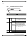
CONTENTS
About This Guide
xi
Document Revision History
Audience
Purpose
xi
xi
xii
Organization
xii
Document Conventions xii
Warning Definition xiv
Related Documentation
xix
Obtaining Documentation, Obtaining Support, and Security Guidelines
PART
ATM Line Cards
1
CHAPTER
1
4-Port OC-3/STM-1 ATM Line Card Overview
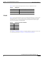
Line Card Summary
1-2
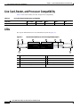
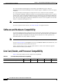
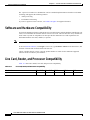
Line Card, Router, and Processor Compatibility
LEDs
Slot Locations
1-4
1-5
Cables and Connectors
1-6
8-Port E3/DS3 ATM Line Card Overview
Line Card Summary
2-1
2-1
Software and Hardware Compatibility
2-2
Line Card, Router, and Processor Compatibility
LEDs
Slot Locations
2-4
2-5
Cables and Connectors
3
2-3
2-3
Physical Specifications
CHAPTER
1-3
1-3
Physical Specifications
2
1-1
1-1
Software and Hardware Compatibility
CHAPTER
xix
2-6
1-Port OC-12 ATM Line Card Overview
Line Card Summary
3-1
3-1
Cisco 10000 Series Routers Line Card Hardware Installation Guide
OL-6773-04
iii
Contents
Software and Hardware Compatibility
3-2
Line Card, Router, and Processor Compatibility
LEDs
3-3
Physical Specifications
Slot Locations
3-6
Channelized Line Cards
2
CHAPTER
3-4
3-5
Cables and Connectors
PART
4
4-Port Channelized T3 Half-Height Line Card Overview
Line Card Summary
4-2
Line Card, Router, and Processor Compatibility
LEDs
4-2
4-3
Physical Specifications
Slot Locations
4-4
4-5
Cables and Connectors 4-6
Cables 4-6
Optional Y-Cables 4-7
Configuration Summary
5
4-1
4-1
Software and Hardware Compatibility
CHAPTER
3-2
4-9
24-Port Channelized E1/T1 Line Card Overview
5-1
Line Card Summary 5-1
E1 Features 5-2
T1 Features 5-2
Software and Hardware Compatibility
5-3
Line Card, Router, and Processor Compatibility
LEDs
5-4
5-4
Physical Specifications
Slot Locations
5-5
5-6
Cables, Connectors, and Pinouts 5-7
Using the BNC Cable Adapter 5-8
Pinouts 5-9
CHAPTER
6
1-Port Channelized OC-12/STM-4 Line Card Overview
Line Card Summary
6-1
6-2
Software and Hardware Compatibility
6-3
Cisco 10000 Series Routers Line Card Hardware Installation Guide
iv
OL-6773-04
Contents
Line Card, Router, and Processor Compatibility
LEDs
6-3
Physical Specifications
Slot Locations
7
6-4
6-5
Cables and Connectors
CHAPTER
6-7
4-Port Channelized OC-3/STM-1 Line Card Overview
Line Card Summary
7-3
Line Card, Router, and Processor Compatibility
LEDs
Slot Locations
7-5
7-6
Cables and Connectors
7-8
6-Port Channelized T3 Line Card Overview
Line Card Summary
8-1
8-1
Software and Hardware Compatibility
8-2
Line Card, Router, and Processor Compatibility
LEDs
Slot Locations
8-4
8-5
Cables and Connectors
8-6
Fast Ethernet and Gigabit Ethernet
Line Cards
3
CHAPTER
8-2
8-3
Physical Specifications
PART
7-3
7-3
Physical Specifications
8
7-1
7-2
Software and Hardware Compatibility
CHAPTER
6-3
9
8-Port Fast Ethernet Half-Height Line Card Overview
Line Card Summary
9-1
Software and Hardware Compatibility
9-2
Line Card, Router, and Processor Compatibility
LEDs
9-1
9-2
9-3
Physical Specifications
Slot Locations
9-4
9-5
Cables, Connectors, and Pinouts 9-6
Cable and Connector Information 9-6
Cisco 10000 Series Routers Line Card Hardware Installation Guide
OL-6773-04
v
Contents
Pinouts
CHAPTER
10
9-7
1-Port Gigabit Ethernet Half-Height Line Card Overview
Line Card Summary
10-1
Software and Hardware Compatibility
10-3
Line Card, Router, and Processor Compatibility
LEDs
10-1
10-3
10-4
Physical Specifications
Slot Locations
10-5
10-6
Cables and Connectors
10-7
SFP Module Configurations and Specifications 10-9
Related Documentation 10-10
Mode-Conditioning Gigabit Ethernet Patch Cord Description
CHAPTER
11
1-Port Gigabit Ethernet Line Card Overview
Line Card Summary
11-1
11-1
Software and Hardware Compatibility
11-2
Line Card, Router, and Processor Compatibility
LEDs
11-2
11-3
Physical Specifications
Slot Locations
11-4
11-5
Cables and Connectors 11-6
Specifications for the Gigabit Ethernet GBIC Module 11-7
Mode-Conditioning Gigabit Ethernet Patch Cord Description
PART
11-8
Packet over SONET Line Cards
4
CHAPTER
10-11
12
6-Port OC-3/STM-1 Packet over SONET Line Card Overview
Line Card Summary
12-1
Software and Hardware Compatibility
12-2
Line Card, Router, and Processor Compatibility
LEDs
12-1
12-2
12-3
Physical Specifications
Slot Locations
12-4
12-5
Cables and Connectors
12-7
Cisco 10000 Series Routers Line Card Hardware Installation Guide
vi
OL-6773-04
Contents
CHAPTER
13
1-Port OC-12 Packet over SONET Line Card Overview
Line Card Summary
13-1
Software and Hardware Compatibility
13-2
Line Card, Router, and Processor Compatibility
LEDs
Slot Locations
13-4
13-5
Cables and Connectors
14
13-7
1-Port OC-48/STM-16 Packet over SONET Line Card Overview
Line Card Summary
14-2
Line Card, Router, and Processor Compatibility
LEDs
Slot Locations
14-5
14-6
Cables and Connectors
14-7
E3/T3 Unchannelized Line Card
5
15
8-Port Unchannelized E3/T3 Line Card Overview
Line Card Summary
15-2
Line Card, Router, and Processor Compatibility
LEDs
15-2
15-3
Physical Specifications
Slot Locations
15-4
15-5
Cables and Connectors
15-7
Installation
6
CHAPTER
15-1
15-1
Software and Hardware Compatibility
PART
14-3
14-3
Physical Specifications
CHAPTER
14-1
14-1
Software and Hardware Compatibility
PART
13-2
13-3
Physical Specifications
CHAPTER
13-1
16
Preparing for Installation
16-1
Required Tools and Equipment
16-1
Safety Guidelines 16-1
Safety Warnings 16-2
Electrical Equipment Guidelines
16-2
Cisco 10000 Series Routers Line Card Hardware Installation Guide
OL-6773-04
vii
Contents
Telephone Wiring Guidelines 16-2
Preventing Electrostatic Discharge Damage
Laser/LED Safety 16-3
CHAPTER
17
Installing and Removing Line Cards
Handling Line Cards
16-3
17-1
17-1
Online Insertion and Removal
17-2
Preprovisioning Line Card Slots
Slot and Subslot Locations
17-3
17-3
Removing and Installing Line Cards 17-7
Removing the Cisco 10008 Front Cover
Installing Full-Size Line Cards 17-10
Replacement Installation Guidelines
17-8
17-10
Installing Half-Height Line Cards 17-16
Replacement Installation Guidelines 17-16
Installing the Half-Height Line Card Carrier 17-16
Installing a Half-Height Line Card Into a Carrier 17-21
Installing SFP Modules or GBIC Modules 17-26
Guidelines for Using SFP Modules or GBIC Modules
Installing an SFP Module or GBIC Module 17-27
Installing an SFP Module 17-28
Installing a GBIC Module 17-30
17-26
Attaching Cables 17-32
Attaching Multimode and Single-Mode Optical Fiber Cables 17-32
Attaching RJ-45 Ethernet Cables 17-35
Attaching the 24-Port Channelized E1/T1 Line Card Adapter Cable 17-36
Attaching Coaxial Cables 17-37
Attaching the 4-Port Channelized T3 Half-Height Line Card Optional Y-Cables
Configuration Summary 17-41
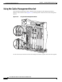
Using the Cable-Management Bracket
17-42
Removing an SFP Module or GBIC Module
Removing Full-Size Line Cards
17-39
17-43
17-46
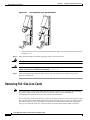
Removing Half-Height Line Cards and Carrier 17-51
Removing a Half-Height Line Card 17-51
Removing a Carrier 17-55
Checking the Installation 17-58
Using show Commands to Verify Line Card Status 17-58
Using show Commands to Display Line Card Information 17-59
Cisco 10000 Series Routers Line Card Hardware Installation Guide
viii
OL-6773-04
Contents
Using the ping Command to Verify Network Connectivity
Configuring a Line Card
CHAPTER
18
17-59
17-60
Troubleshooting the Installation
18-1
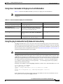
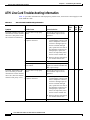
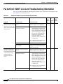
ATM Line Card Troubleshooting Information
18-2
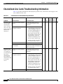
Channelized Line Cards Troubleshooting Information
18-6
Fast Ethernet and Gigabit Ethernet Line Card Troubleshooting Information
Packet Over SONET Line Card Troubleshooting Information
Unchannelized E3/T3 Line Card Troubleshooting Information
Cleaning the Fiber-Optic Connections
Checking Flow Control
APPENDIX
A
18-11
18-20
18-23
18-24
18-24
Cisco 10005 Extender Card Information
.Installation Guidelines 19-1
Required Tools and Equipment
19-1
19-2
Installing or Replacing Extender Cards 19-2
Installing an Extender Card 19-2
Removing an Extender Card 19-3
Troubleshooting 19-3
INDEX
Cisco 10000 Series Routers Line Card Hardware Installation Guide
OL-6773-04
ix
Contents
Cisco 10000 Series Routers Line Card Hardware Installation Guide
x
OL-6773-04
About This Guide
Document Revision History
The Document Revision History table, below, records technical changes to this document.
Revisoin
Date
Change Summary
OL-6773-04
July 2007
Added 1000BASE-T SFP transceiver module for
Category 5 copper wire support for the 1-port Gigabit
Ethernet half-height line card.
December 2006
Added Performance Routing Engine 3 (PRE3) software
support information for the following line cards:1-port
OC-12 ATM, 1-port channelized OC-12/STM-4, 1-port
Gigabit Ethernet half-height, and 1-port Gigabit Ethernet.
OL-6773-03
May 2006
Added Coarse Wave Division Multiplexer (CWDM) Small
Form-Factor Pluggable (SFP) laser optical transceiver
module information.
OL-6773-02
March 2006
Added information about these line cards: 4-port
channelized T3 half-height and 4-port OC-3/STM-1 ATM
with long-reach optics.
OL-6773-01
July 2005
This document contains all of the Cisco 10000 series
routers line card information previously documented in
individual documents, including the Cisco 10005 extender
card and alarm card document.
Regulatory compliance and safety information has moved
to the new Regulatory Compliance and Safety Information
for the Cisco 10000 Series Routers.
Audience
The Cisco 10000 Series Routers Line Card Hardware Installation Guide is written for the person who
installs, configures, and maintains a Cisco 10000 series router.
The user must be familiar with electronic circuitry and wiring practices and have experience as an
electronic or electromechanical technician.
Cisco 10000 Series Routers Line Card Hardware Installation Guide
OL-6773-04
xi
About This Guide
Purpose
Purpose
This guide presents hardware installation and basic configuration procedures for the Cisco 10000 line
cards and includes the following information:
•
Line card overview, specifications, and compatibility
•
Installing the hardware
•
Starting up the router
•
Configuring basic functionality
Organization
The Cisco 10000 Series Routers Line Card Hardware Installation Guide is organized as follows:
Chapter/Appendix
Number
Title
Description
Chapters 1 to 15
Product Overview
Each chapter provides overview information for a specific Cisco 10000
series router line card, including minimum software release
information, hardware and software compatibility information,
specifications, cabling information, and LED information
Chapter 16
Preparing for Installation
This chapter contains information on tools requirements, safety
guidelines, site requirements for power, environmental safety, and
electrostatic discharge (ESD).
Chapter 17
Installing and Removing Line
Cards
This chapter contains the instructions for installing and removing line
cards in the Cisco 10000 series routers.
Chapter 18
Troubleshooting the
Installation
This chapter provides hardware troubleshooting information.
Appendix A
Cisco 10005 Extender Card
Information
This appendix provides information about the Cisco 10005 extender
card, including information about removing and installing it.
Document Conventions
This document uses the following conventions:
Convention
Description
^ or Ctrl
The ^ and Ctrl symbols represent the Control key. For example, the key
combination ^D or Ctrl-D means hold down the Control key while you press the
D key. Keys are indicated in capital letters but are not case sensitive.
string
A string is a nonquoted set of characters shown in italics. For example, when
setting an SNMP community string to public, do not use quotation marks around
the string or the string will include the quotation marks.
Cisco 10000 Series Routers Line Card Hardware Installation Guide
xii
OL-6773-04
About This Guide
Document Conventions
Command syntax descriptions use the following conventions:
Convention
Description
bold
Bold text indicates commands and keywords that you enter literally as shown.
italics
Italic text indicates arguments for which you supply values.
[x]
Square brackets enclose an optional element (keyword or argument).
|
A vertical line indicates a choice within an optional or required set of keywords
or arguments.
[x | y]
Square brackets enclosing keywords or arguments separated by a vertical line
indicate an optional choice
{x | y}
Braces enclosing keywords or arguments separated by a vertical line indicate a
required choice.
Nested sets of square brackets or braces indicate optional or required choices within optional or required
elements. For example:
Convention
Description
[x {y | z}]
Braces and a vertical line within square brackets indicate a required choice within
an optional element.
Examples use the following conventions:
Convention
Description
screen
Examples of information displayed on the screen are set in Courier font.
bold screen
Examples of text that you must enter are set in Courier bold font.
< >
Angle brackets enclose text that is not printed to the screen, such as passwords.
!
An exclamation point at the beginning of a line indicates a comment line.
(Exclamation points are also displayed by the Cisco IOS software for certain
processes.)
[ ]
Square brackets enclose default responses to system prompts.
The following conventions are used to attract the attention of the reader:
Caution
Note
Means reader be careful. In this situation, you might do something that could result in equipment damage
or loss of data.
Means reader take note. Notes contain helpful suggestions or references to materials not contained in
this manual.
Cisco 10000 Series Routers Line Card Hardware Installation Guide
OL-6773-04
xiii
About This Guide
Document Conventions
Warning Definition
Warning
IMPORTANT SAFETY INSTRUCTIONS
This warning symbol means danger. You are in a situation that could cause bodily injury. Before you
work on any equipment, be aware of the hazards involved with electrical circuitry and be familiar
with standard practices for preventing accidents. Use the statement number provided at the end of
each warning to locate its translation in the translated safety warnings that accompanied this
device. Statement 1071
SAVE THESE INSTRUCTIONS
Waarschuwing
BELANGRIJKE VEILIGHEIDSINSTRUCTIES
Dit waarschuwingssymbool betekent gevaar. U verkeert in een situatie die lichamelijk letsel kan
veroorzaken. Voordat u aan enige apparatuur gaat werken, dient u zich bewust te zijn van de bij
elektrische schakelingen betrokken risico's en dient u op de hoogte te zijn van de standaard
praktijken om ongelukken te voorkomen. Gebruik het nummer van de verklaring onderaan de
waarschuwing als u een vertaling van de waarschuwing die bij het apparaat wordt geleverd, wilt
raadplegen.
BEWAAR DEZE INSTRUCTIES
Varoitus
TÄRKEITÄ TURVALLISUUSOHJEITA
Tämä varoitusmerkki merkitsee vaaraa. Tilanne voi aiheuttaa ruumiillisia vammoja. Ennen kuin
käsittelet laitteistoa, huomioi sähköpiirien käsittelemiseen liittyvät riskit ja tutustu
onnettomuuksien yleisiin ehkäisytapoihin. Turvallisuusvaroitusten käännökset löytyvät laitteen
mukana toimitettujen käännettyjen turvallisuusvaroitusten joukosta varoitusten lopussa näkyvien
lausuntonumeroiden avulla.
SÄILYTÄ NÄMÄ OHJEET
Attention
IMPORTANTES INFORMATIONS DE SÉCURITÉ
Ce symbole d'avertissement indique un danger. Vous vous trouvez dans une situation pouvant
entraîner des blessures ou des dommages corporels. Avant de travailler sur un équipement, soyez
conscient des dangers liés aux circuits électriques et familiarisez-vous avec les procédures
couramment utilisées pour éviter les accidents. Pour prendre connaissance des traductions des
avertissements figurant dans les consignes de sécurité traduites qui accompagnent cet appareil,
référez-vous au numéro de l'instruction situé à la fin de chaque avertissement.
CONSERVEZ CES INFORMATIONS
Cisco 10000 Series Routers Line Card Hardware Installation Guide
xiv
OL-6773-04
About This Guide
Document Conventions
Warnung
WICHTIGE SICHERHEITSHINWEISE
Dieses Warnsymbol bedeutet Gefahr. Sie befinden sich in einer Situation, die zu Verletzungen führen
kann. Machen Sie sich vor der Arbeit mit Geräten mit den Gefahren elektrischer Schaltungen und
den üblichen Verfahren zur Vorbeugung vor Unfällen vertraut. Suchen Sie mit der am Ende jeder
Warnung angegebenen Anweisungsnummer nach der jeweiligen Übersetzung in den übersetzten
Sicherheitshinweisen, die zusammen mit diesem Gerät ausgeliefert wurden.
BEWAHREN SIE DIESE HINWEISE GUT AUF.
Avvertenza
IMPORTANTI ISTRUZIONI SULLA SICUREZZA
Questo simbolo di avvertenza indica un pericolo. La situazione potrebbe causare infortuni alle
persone. Prima di intervenire su qualsiasi apparecchiatura, occorre essere al corrente dei pericoli
relativi ai circuiti elettrici e conoscere le procedure standard per la prevenzione di incidenti.
Utilizzare il numero di istruzione presente alla fine di ciascuna avvertenza per individuare le
traduzioni delle avvertenze riportate in questo documento.
CONSERVARE QUESTE ISTRUZIONI
Advarsel
VIKTIGE SIKKERHETSINSTRUKSJONER
Dette advarselssymbolet betyr fare. Du er i en situasjon som kan føre til skade på person. Før du
begynner å arbeide med noe av utstyret, må du være oppmerksom på farene forbundet med
elektriske kretser, og kjenne til standardprosedyrer for å forhindre ulykker. Bruk nummeret i slutten
av hver advarsel for å finne oversettelsen i de oversatte sikkerhetsadvarslene som fulgte med denne
enheten.
TA VARE PÅ DISSE INSTRUKSJONENE
Aviso
INSTRUÇÕES IMPORTANTES DE SEGURANÇA
Este símbolo de aviso significa perigo. Você está em uma situação que poderá ser causadora de
lesões corporais. Antes de iniciar a utilização de qualquer equipamento, tenha conhecimento dos
perigos envolvidos no manuseio de circuitos elétricos e familiarize-se com as práticas habituais de
prevenção de acidentes. Utilize o número da instrução fornecido ao final de cada aviso para
localizar sua tradução nos avisos de segurança traduzidos que acompanham este dispositivo.
GUARDE ESTAS INSTRUÇÕES
¡Advertencia!
INSTRUCCIONES IMPORTANTES DE SEGURIDAD
Este símbolo de aviso indica peligro. Existe riesgo para su integridad física. Antes de manipular
cualquier equipo, considere los riesgos de la corriente eléctrica y familiarícese con los
procedimientos estándar de prevención de accidentes. Al final de cada advertencia encontrará el
número que le ayudará a encontrar el texto traducido en el apartado de traducciones que acompaña
a este dispositivo.
GUARDE ESTAS INSTRUCCIONES
Cisco 10000 Series Routers Line Card Hardware Installation Guide
OL-6773-04
xv
About This Guide
Document Conventions
Varning!
VIKTIGA SÄKERHETSANVISNINGAR
Denna varningssignal signalerar fara. Du befinner dig i en situation som kan leda till personskada.
Innan du utför arbete på någon utrustning måste du vara medveten om farorna med elkretsar och
känna till vanliga förfaranden för att förebygga olyckor. Använd det nummer som finns i slutet av
varje varning för att hitta dess översättning i de översatta säkerhetsvarningar som medföljer denna
anordning.
SPARA DESSA ANVISNINGAR
Cisco 10000 Series Routers Line Card Hardware Installation Guide
xvi
OL-6773-04
About This Guide
Document Conventions
Aviso
INSTRUÇÕES IMPORTANTES DE SEGURANÇA
Este símbolo de aviso significa perigo. Você se encontra em uma situação em que há risco de lesões
corporais. Antes de trabalhar com qualquer equipamento, esteja ciente dos riscos que envolvem os
circuitos elétricos e familiarize-se com as práticas padrão de prevenção de acidentes. Use o
número da declaração fornecido ao final de cada aviso para localizar sua tradução nos avisos de
segurança traduzidos que acompanham o dispositivo.
GUARDE ESTAS INSTRUÇÕES
Advarsel
VIGTIGE SIKKERHEDSANVISNINGER
Dette advarselssymbol betyder fare. Du befinder dig i en situation med risiko for
legemesbeskadigelse. Før du begynder arbejde på udstyr, skal du være opmærksom på de
involverede risici, der er ved elektriske kredsløb, og du skal sætte dig ind i standardprocedurer til
undgåelse af ulykker. Brug erklæringsnummeret efter hver advarsel for at finde oversættelsen i de
oversatte advarsler, der fulgte med denne enhed.
GEM DISSE ANVISNINGER
Cisco 10000 Series Routers Line Card Hardware Installation Guide
OL-6773-04
xvii
About This Guide
Document Conventions
Cisco 10000 Series Routers Line Card Hardware Installation Guide
xviii
OL-6773-04
About This Guide
Related Documentation
We recommend that you read and understand the safety warnings and guidelines before installing,
configuring, or maintaining the router. See the Regulatory Compliance and Safety Information for the
Cisco 10000 Series Routers document.
Related Documentation
For a complete list of all Cisco 10000 series routers documentation, see the online Cisco 10000 Series
Routers Documentation Roadmap. See also the following documents:
•
Regulatory Compliance and Safety Information for the Cisco 10000 Series Routers
•
Cisco 10000 Series Router Line Card Configuration Guide
•
Cisco 10000 Series Router Performance Routing Engine Installation
Obtaining Documentation, Obtaining Support, and Security
Guidelines
For information on obtaining documentation, obtaining support, providing documentation feedback,
security guidelines, and also recommended aliases and general Cisco documents, see the monthly
What’s New in Cisco Product Documentation, which also lists all new and revised Cisco technical
documentation, at:
http://www.cisco.com/en/US/docs/general/whatsnew/whatsnew.html
Cisco 10000 Series Routers Line Card Hardware Installation Guide
OL-6773-04
xix
About This Guide
Obtaining Documentation, Obtaining Support, and Security Guidelines
Cisco 10000 Series Routers Line Card Hardware Installation Guide
xx
OL-6773-04
PA R T
1
ATM Line Cards
C H A P T E R
1
4-Port OC-3/STM-1 ATM Line Card Overview
This chapter describes the Cisco 10000 series 4-port OC-3/STM-1c ATM line card (referred to as the
4-port OC-3/STM-1 ATM line card), and contains the following sections:
•
Line Card Summary, page 1-1
•
Software and Hardware Compatibility, page 1-2
•
Line Card, Router, and Processor Compatibility, page 1-3
•
LEDs, page 1-3
•
Physical Specifications, page 1-4
•
Slot Locations, page 1-5
•
Cables and Connectors, page 1-6
Line Card Summary
Table 1-1
4-Port OC-3/STM-1 ATM Line Card Summary
Product Number
Description
Minimum Cisco IOS Release
ESR-4OC3-ATM-SM=
4-port OC-3/STM-1 ATM
line card with
intermediate-reach optics
Initial Cisco IOS releases for PRE-1:
12.0(21)SX and later releases of Cisco IOS Release 12.0SX
12.0(20)ST and later releases of Cisco IOS Release 12.0ST
12.0(22)S and later releases of Cisco IOS Release 12.0S
12.2(8)BZ and later releases of Cisco IOS Release 12.2BZ
Initial Cisco IOS releases for PRE-2:
12.3(7)XI and later releases of
12.3XI
12.2(15)BX and later releases of
12.2BX
12.2(28)SB and later releases of Cisco IOS Release 12.2(28)SB
ESR-4OC3-ATM-SM-LR=
4-port OC-3/STM-1 ATM
line card with long-reach
optics
12.2(28)SB and later releases of Cisco IOS Release 12.2(28)SB
For registered Cisco.com users, use Software Advisor to
determine the software releases for this line card.
Cisco 10000 Series Routers Line Card Hardware Installation Guide
OL-6773-04
1-1
Chapter 1
4-Port OC-3/STM-1 ATM Line Card Overview
Software and Hardware Compatibility
The 4-port OC-3/STM-1 ATM line card is a NEBS-compliant device that performs Layer 2
Asynchronous Transfer Mode (ATM) functions. This line card receives and transmits ATM cells on each
network physical interface connected to a line card port, and simultaneously transmits and receives
packets from the Cisco 10000 series router backplane.
This line card can be used to:
•
Provide four OC-3 trunk uplinks
•
Provide IP packet routing over ATM virtual circuit connections using single-mode fiber
intermediate reach and long reach LC connectors at each port
•
Operate as a subscriber interface card
The 4-port OC-3/STM-1 ATM line card is an implementation of ATM over SONET switching. This line
card supports the following features:
•
Conforms to the ATM forum ATM UNI 3.1 155.52-Mbps physical layer specification
•
Uses ATM cell header 8-bit virtual path identifiers (VPIs) and 16-bit virtual channel identifiers
(VCIs)
•
Provides ATM QoS (quality of service) management
•
Complies with the SONET/SDH OC-3 STS-3/STM-1 framing format
•
Accommodates SONET overhead bits
•
Provides up to 8191 total connections
•
Provides alarm processing
•
Provides continuous performance monitoring
If you are a registered Cisco.com user, see Feature Navigator for supported features.
Software and Hardware Compatibility
To check the minimum software requirements of Cisco IOS software with the hardware installed on your
router, Cisco maintains the Software Advisor tool on Cisco.com. This tool does not verify whether line
cards within a system are compatible, but does provide the minimum Cisco IOS requirements for
individual hardware line cards, modules, or options.
Note
Access to this tool is limited to users with Cisco.com login accounts.
To access Software Advisor, click Login at Cisco.com, type “Software Advisor” in the SEARCH box,
and click Go. Click the link for the Software Advisor tool.
Choose a product family or enter a specific product number to search for the minimum supported
software release needed for your hardware.
Cisco 10000 Series Routers Line Card Hardware Installation Guide
1-2
OL-6773-04
Chapter 1
4-Port OC-3/STM-1 ATM Line Card Overview
Line Card, Router, and Processor Compatibility
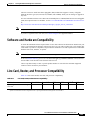
Line Card, Router, and Processor Compatibility
Table 1-2 provides information about the router model, line card, and processor compatibility.
Table 1-2
Line Card, Router, and Processor Compatibility
Line Card
Cisco 10008
Cisco 10005
PRE-2
PRE-1
PRE
4-port OC-3/STM-1 ATM line card
ESR-4OC-ATM-SM=
Yes
Yes
Yes
Yes
Yes
4-port OC-3/STM-1 ATM line card
ESR-4OC-ATM-SM-LR=
Yes
No
Yes
No
No
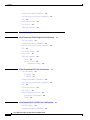
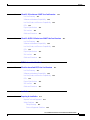
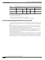
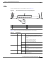
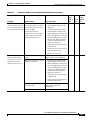
LEDs
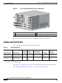
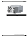
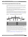
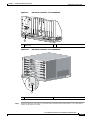
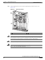
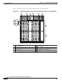
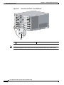
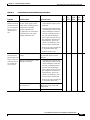
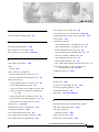
The 4-port OC-3/STM-1 ATM line card LEDs are described in Figure 1-1.
Figure 1-1
4-Port OC-3/STM-1 ATM Line Card Faceplate Description
2
4
3
8
7
5
9
4XOC-3/STM-1 ATM SM-IR
59314
3
2
1
OP
LO
RM
A
AL D
C
2
3
OP
LO
M
AR
AL
CD
OP
LO
M
AR
AL D
C
0
L
I
FA
0
1
CISCO
10000
1
6
2
3
0
1
OP
LO
M
R
A
AL CD
1
Top captive screw
6
Ports 2 and 3 status LED group
2
Top ejector lever
7
Lower ejector lever
3
Yellow line card Fail LED
8
Cable management clip
4
Ports 0 and 1 Status LED group
9
Lower captive screw
5
Ports 0 to 3 RX and TX connectors
Cisco 10000 Series Routers Line Card Hardware Installation Guide
OL-6773-04
1-3
Chapter 1
4-Port OC-3/STM-1 ATM Line Card Overview
Physical Specifications
Table 1-3 provides a description of the 4-port OC-3/STM-1 ATM line card LEDs.
Table 1-3
LED Description
LED Label
Color
State
Meaning
FAIL
Yellow
Off
Off when line card is working properly. Turns on for a few
seconds during line card power-on self test (POST), then
turns off when the line card is working properly.
On
On when the line card POST fails.
Off
Off when the line card is available for normal operation.
On
On when some portion of the corresponding port data is in
a loopback state and is not available for normal operations.
Off
Off when the line card is operating normally.
On
On when an alarm condition exists at the corresponding
port.
On
On when a carrier is detected at the corresponding port.
Off
Off when a loss of signal (LOS) is indicated.
LOOP
Yellow
ALARM
Yellow
CD (carrier
detected)
Green
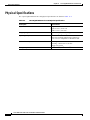
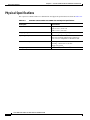
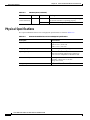
Physical Specifications
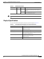
The 4-port OC-3/STM-1 ATM line card physical specifications are shown in Table 1-4:
Table 1-4
4-Port OC-3/STM-1 ATM Line Card Physical Specifications
Description
Specifications
Physical dimensions
Height: 16.0 in. (40.64 cm)
Depth: 9.97 in. (25.32 cm)
Width: 1.12 in. (2.83 cm)
Shipping weight
Approximately 4.75 lb (2.16 kg)
Operating temperature
41oF to 104oF (5oC to 40oC)
Short-term operating temperature is limited to
131oF (55oC) in compliance with Bellcore GR
Relative humidity
Operating—nominal: 5% to 85%
Operating—short term: 5% to 90%
Storage: 5% to 95%
Storage temperature
–40oF to 158oF (–40oC to 70C o)
Cisco 10000 Series Routers Line Card Hardware Installation Guide
1-4
OL-6773-04
Chapter 1
4-Port OC-3/STM-1 ATM Line Card Overview
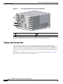
Slot Locations
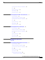
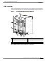
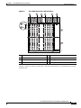
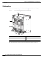
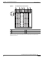
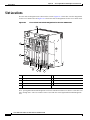
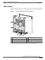
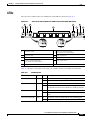
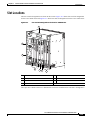
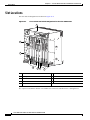
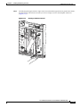
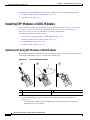
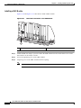
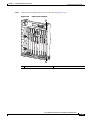
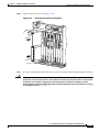
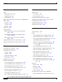
Slot Locations
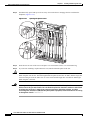
The line card slot designations are shown in this section. Figure 1-2 shows line card slot designations
for the Cisco 10008 router and Figure 1-3 shows line card slot designations for the Cisco 10005 router.
Figure 1-2
Line Card Slot Designations for the Cisco 10008 Router
1
FANS
OK
FAN
FAILURE
MULTIFAN
FAILURE
When hot CAUTION
removal swapping
this fan
be done and replaceme
tray,
system in under two nt must
shutdown
minu
will occutes or
r.
1
2
CISCO
10000
3
FA
CISCO
10000
4
0A
PROC
ESSO
0B
R ONLY
C10
CISC
000
O
1000
6CT30
IL
FA
IL
FA
IL
FA
IL
CISCO
10000
CISCO
10000
5
CISCO
10000
6
C10
CISC
000
O
1000
6CT30
FAIL
7
FA
C10
CISC
000
O
1000
6CT30
N
O
O
LE
FAIL
X
OP
M
AR
R
IE
LO
AL
OP
RR
M
AR
R
IE
LO
CA
AL
RR
O
AU
AU
X
M
0 0 CA ALARLOOP
PORT
AC
TI
IT
OP
M
AR
R
IE
LO
AL
M
0 0 CA ALARLOOP
PORT
RR
T
M
0 0 CA ALARLOOP
PORT
Y
VIT
K
N
TI
Y
LI
AC
VIT
K
N
TI
LI
AC
K
M
0 0 CA ALARLOOP
PORT
CA
E
OP
N
M
AR
R
IE
R
LO
E
N
AL
T
LI
1 1
PORT
Y
TH
E
K
RR
E
N
N
IT
CA
LI
OP
LO
M
AR
R
IE
V
R
AL
TI
E
1
RR
AC
Y
TH
CA
V
E
2
1 1
PORT
ALARMS
PORT
2 2
1 1
PORT
1 1
PORT
ALARMS
C
POWER
R
IT
R
PORT
2 2
IN
AJO
AL
M
IC
R
M
PORT
2 2
IN
R
M
R
O
O
O
R
AC
4
PORT
2 2
IT
AL
AJO
M
OP
R
IE
AR
LO
RX
AL
TX
RR
NK
CA
PORT
3 3
C
IC
M
3
LI
FAULT
MISWIR
E
FAIL
S
IL
CA
N
0
FA
FAIL
C
LE
IL
S
2
CISCO
10000
FA
IL
O
8
C10
CISC
000
O
1000
6CT30
FA
IL
C
PORT
3 3
AC
PORT
3 3
O
PORT
4 4
PORT
3 3
CA
5
RR
PORT
4 4
PORT
5 5
RX
R
PORT
4 4
TX
IE
PORT
4 4
PORT
5 5
PORT
5 5
PORT
5 5
T
SLO
T
SLO
0
0
S
TU IL
STA FA
3
S
TU IL
STA FA
BIT
S
BIT
S
6XCT3–DS0
OC–12/STM–4 POS SM–IR
6XCT3–DS0
6XCT3–DS0
P/N ESR-PRE3
P/N ESR-PRE3
PERFORMANCE ROUTING ENGINE
PERFORMANCE ROUTING ENGINE
6XCT3–DS0
6XCT3–DS0
CH OC-12-DSO SM-IR
GIGABIT ETHERNET
POWER
FAULT
MISWIR
E
PROC
ESSO
4
132515
R ONLY
5
6
7
1
Blower module
5
PRE slot 0A
2
Primary PEM
6
PRE slot 0B
3
Redundant PEM
7
Line card slots 5 to 8
4
Line card slots 1 to 4
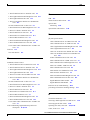
The 4-port OC-3/STM-1 ATM line card can be installed in line card slot 1 through slot 8.
Cisco 10000 Series Routers Line Card Hardware Installation Guide
OL-6773-04
1-5
Chapter 1
4-Port OC-3/STM-1 ATM Line Card Overview
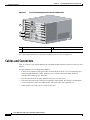
Cables and Connectors
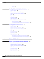
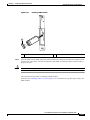
CISCO
10000
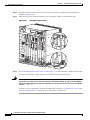
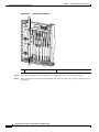
Line Card Slot Designations for the Cisco 10005 Router
FAIL
CISCO
10000
Figure 1-3
FAIL
RX
CISCO
10000
FAIL
CISCO
10000
FAIL
CISCO
10000
3
TX
OC-12/STM
IER
-4 POS
RR
CA
FAIL
SM-IR
RX
TX
OC-12/STM
IER
-4 POS
RR
CA
SM-IR
OP
LO
M
ALAR
IER
RR
2
1
0
CA
6XCT3–DS
5
4
3
0
OP
LO
M
ALAR
IER
RR
2
1
0
CA
6XCT3–DS
5
4
3
0
OP
AU
TIVI
TY
HER
LIN NET
K
AC
X
LE
M
ALAR
LE
AB
EN
SLOT
TX
OC-12/STM
-4 ATM
IER
RR
CA
SM-IR
PERFORM
ANCE
1
ROUTING
ENGINE
US
132516
ST
AT
FA
IL
O
OR
AC
CR
ITIC
AL
MAJ
MIN
OR
PERFORM
ENGINE
FA
IL
O
OR
AC
CR
ITIC
AL
ROUTING
ST
AT
US
ANCE
1
0
MAJ
SLOT
SLOT
MIN
OR
AU
X
AC
TIVI
TY
HER
LIN NET
K
LE
0
ET
CO
NSO
CISCO
10000
SLOT
1
RX
ET
CO
NSO
2
CISCO
10000
LO
1
PRE slot A
2
PRE slot B
3
Line card slots 1 (top) to 5 (bottom)
The 4-port OC-3/STM-1 ATM line card can be installed in line card slot 1 through slot 5.
Cables and Connectors
Table 1-5 provides optical cable specifications for the line card.
Table 1-5
Optical Specifications
Maximum Minimum
Power to Receiver
Receiver Sensitivity
Transceiver Type
Transmit Power
Single-mode
intermediate reach
–15 dBm minimum to –8 dBm
–8 dBm maximum
Single-mode long
reach (LR)
–5 dBm minimum to
0 dBm maximum
–28 dBm
–10 dBm1 –34 dBm
Nominal Distance
Between Stations
Wavelength
Fiber Type:
Single Mode
1280 nm to
1335 nm
Core size 8 to 10
microns
Up to 25 mi (40 km) 1280 nm to
1335 nm
Core size 8 to 10
microns
Up to 9 mi (15 km)
1. For LR, a minimum of 10 dB of total attenuation between transmitter and receiver is required. Exceeding the maximum
receive power can damage the optics.
Go to Chapter 16, “Preparing for Installation” to begin the installation or replacement of the line card.
For troubleshooting information, see Chapter 18, “Troubleshooting the Installation.”
Cisco 10000 Series Routers Line Card Hardware Installation Guide
1-6
OL-6773-04
C H A P T E R
2
8-Port E3/DS3 ATM Line Card Overview
This chapter describes the Cisco 10000 series 8-port E3/DS3 ATM line card (referred to as the 8-port
E3/DS3 ATM line card) and contains the following sections:
•
Line Card Summary, page 2-1
•
Software and Hardware Compatibility, page 2-2
•
Line Card, Router, and Processor Compatibility, page 2-3
•
LEDs, page 2-3
•
Physical Specifications, page 2-4
•
Slot Locations, page 2-5
•
Cables and Connectors, page 2-6
Line Card Summary
Table 2-1
8-Port E3/DS3 ATM Line Card Summary
Product Number
Description
Minimum Cisco IOS Release
ESR-8E3DS3-ATM=
8-port E3/DS3 ATM line card
Initial Cisco IOS releases for PRE-2:
12.2(16)BX and later releases of Cisco IOS Release 12.2BX
12.2(28)SB and later releases of Cisco IOS Release 12.2(28)SB
12.3(7)XI and later releases of Cisco IOS Release 12.3XI
For registered Cisco.com users, use Software Advisor to
determine the software releases for this line card.
The 8-port E3/DS3 ATM line card has eight E3 or DS3 (T3) copper interface terminations that provide
Asynchronous Transfer Mode (ATM) serial interfaces and perform Layer 2 ATM functions.
Each E3/DS3 interface port on the 8-port E3/DS3 ATM line card provides a single high-speed data
channel.
•
Maximum E3 bandwidth—34.386 Mbps
•
Maximum DS3 bandwidth—44.736 Mbps
The 8-port E3/DS3 ATM line card can be used to:
Cisco 10000 Series Routers Line Card Hardware Installation Guide
OL-6773-04
2-1
Chapter 2
8-Port E3/DS3 ATM Line Card Overview
Software and Hardware Compatibility
•
Provide eight E3 or DS3 trunk uplinks that support throughput of up to 44.736 Mbps at each port of
the line card
•
Provide IP packet routing over ATM virtual circuit connections using copper-based E3 or DS3
connectors at each port
•
Operate as a subscriber interface card
The ATM features of the 8-port E3/DS3 ATM line card include:
•
Broadband aggregation support for up to 8,000 simultaneously active, independent ATM virtual
circuits per E3 or DS3 port, with a total limit of 32,000 VCs per line card
•
Uses ATM cell header 8-bit virtual path identifiers (VPIs) and 16-bit virtual channel identifiers
(VCIs)
•
Provides ATM QoS (quality of service) management
If you are a registered Cisco.com user, see Feature Navigator for supported features.
Software and Hardware Compatibility
To check the minimum software requirements of Cisco IOS software with the hardware installed on your
router, Cisco maintains the Software Advisor tool on Cisco.com. This tool does not verify whether line
card within a system are compatible, but does provide the minimum Cisco IOS requirements for
individual hardware line cards, modules, or options.
Note
Access to this tool is limited to users with Cisco.com login accounts.
To access Software Advisor, click Login at Cisco.com, type “Software Advisor” in the SEARCH box,
and click Go. Click the link for the Software Advisor tool.
Choose a product family or enter a specific product number to search for the minimum supported
software release needed for your hardware.
Cisco 10000 Series Routers Line Card Hardware Installation Guide
2-2
OL-6773-04
Chapter 2
8-Port E3/DS3 ATM Line Card Overview
Line Card, Router, and Processor Compatibility
Line Card, Router, and Processor Compatibility
Table 2-2 provides information about the router model, line card, and processor compatibility.
Table 2-2
Line Card, Router, and Processor Compatibility
Line Card
Cisco 10008
8-port E3/DS3 ATM line card
Cisco 10005
Yes
No
1
PRE-2
PRE-1
PRE
Yes
No
No
1. The 8-port E3/DS3 ATM line card has been compliance tested to function in a Cisco 10005 chassis.
LEDs
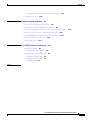
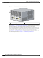
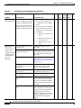
The 8-port E3/DS3 ATM line card LEDs are described in Figure 2-1.
Figure 2-1
8-Port E3/DS3 ATM Line Card Faceplate Description
2
1
1
2
4
ESR-8E3DS3-ATM
C
76317
7
6
5
0
OP
LO
M
AR
AL R
E
RI
AR
4
3
PN 800-19581-02
2
OP
LO
M
AR
AL R
IE
RR
CA
1
L
I
FA
0
CISCO
10000
3
1
Captive screw
3
Yellow Fail LED
2
Ejector lever
4
Ports 0 to 7 status LEDs:
Cisco 10000 Series Routers Line Card Hardware Installation Guide
OL-6773-04
2-3
Chapter 2
8-Port E3/DS3 ATM Line Card Overview
Physical Specifications
Table 2-3 provides a description of the 8-port E3/DS3 ATM line card LEDs.
Table 2-3
LED Description
LED Label
Color
State
Meaning
FAIL
Yellow
Off
Off when line card is working properly. Turns on for a few
seconds during line card power-on self test (POST), then
turns off when the line card is working properly.
On
On when the line card POST fails.
Off
Off when the line card is available for normal operation.
On
On when some portion of the corresponding port data is in
a loopback state and is not available for normal operations.
Off
Off when the line card is operating normally.
On
On when an alarm condition exists at the corresponding
port.
On
On when a carrier is detected at the corresponding port and
the interface is operating properly.
Off
Off when a loss of signal (LOS) is indicated.
LOOP
Yellow
ALARM
Yellow
CARRIER
(carrier
detected)
Green
Physical Specifications
The 8-port E3/DS3 ATM line card physical specifications are shown in Table 2-4.
Table 2-4
8-Port E3/DS3 ATM Line Card Physical Specifications
Description
Specifications
Physical dimensions
Height: 16.0 in. (40.64 cm)
Depth: 9.97 in. (25.32 cm)
Width: 1.12 in. (2.83 cm)
Shipping weight
Approximately 4.75 lb (2.16 kg)
Operating temperature
41oF to 104oF (5oC to 40oC)
Short-term operating temperature is limited to
131oF (55oC) in compliance with Bellcore GR
Relative humidity
Operating—nominal: 5% to 85%
Operating—short term: 5% to 90%
Storage: 5% to 95%
Storage temperature
–40oF to 158oF (–40oC to 70C o)
Cisco 10000 Series Routers Line Card Hardware Installation Guide
2-4
OL-6773-04
Chapter 2
8-Port E3/DS3 ATM Line Card Overview
Slot Locations
Slot Locations
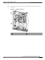
The line card slot designations are shown in this section. Figure 2-2 shows line card slot designations
for the Cisco 10008 router and Figure 2-3 shows line card slot designations for the Cisco 10005 router.
Figure 2-2
Line Card Slot Designations for the Cisco 10008 Router
1
FANS
OK
FAN
FAILURE
MULTIFAN
FAILURE
When hot CAUTION
removal swapping
this fan
be done and replaceme
tray,
system in under two nt must
shutdown
minu
will occutes or
r.
1
2
CISCO
10000
3
FA
CISCO
10000
4
0A
PROC
ESSO
0B
R ONLY
C10
CISC
000
O
1000
6CT30
IL
FA
IL
FA
IL
FA
IL
CISCO
10000
CISCO
10000
5
CISCO
10000
6
C10
CISC
000
O
1000
6CT30
FAIL
7
FA
C10
CISC
000
O
1000
6CT30
N
O
O
LE
FAIL
X
OP
M
AR
R
IE
LO
AL
OP
RR
M
AR
R
IE
LO
CA
AL
RR
O
AU
AU
X
M
0 0 CA ALARLOOP
PORT
AC
TI
IT
OP
M
AR
R
IE
LO
AL
M
0 0 CA ALARLOOP
PORT
RR
T
M
0 0 CA ALARLOOP
PORT
Y
VIT
K
N
TI
Y
LI
AC
VIT
K
N
TI
LI
AC
K
M
0 0 CA ALARLOOP
PORT
CA
E
OP
N
M
AR
R
IE
R
LO
E
N
AL
T
LI
1 1
PORT
Y
TH
E
K
RR
E
N
N
IT
CA
LI
OP
LO
M
AR
R
IE
V
R
AL
TI
E
1
RR
AC
Y
TH
CA
V
E
2
1 1
PORT
ALARMS
PORT
2 2
1 1
PORT
1 1
PORT
ALARMS
C
POWER
R
IT
R
PORT
2 2
IN
AJO
AL
M
IC
R
M
PORT
2 2
IN
R
M
R
O
O
O
R
AC
4
PORT
2 2
IT
AL
AJO
M
OP
R
IE
AR
LO
RX
AL
TX
RR
NK
CA
PORT
3 3
C
IC
M
3
LI
FAULT
MISWIR
E
FAIL
S
IL
CA
N
0
FA
FAIL
C
LE
IL
S
2
CISCO
10000
FA
IL
O
8
C10
CISC
000
O
1000
6CT30
FA
IL
C
PORT
3 3
AC
PORT
3 3
O
PORT
4 4
PORT
3 3
CA
5
RR
PORT
4 4
PORT
5 5
RX
R
PORT
4 4
TX
IE
PORT
4 4
PORT
5 5
PORT
5 5
PORT
5 5
T
SLO
T
SLO
0
0
S
TU IL
STA FA
3
S
TU IL
STA FA
BIT
S
BIT
S
6XCT3–DS0
OC–12/STM–4 POS SM–IR
6XCT3–DS0
6XCT3–DS0
P/N ESR-PRE3
P/N ESR-PRE3
PERFORMANCE ROUTING ENGINE
PERFORMANCE ROUTING ENGINE
6XCT3–DS0
6XCT3–DS0
CH OC-12-DSO SM-IR
GIGABIT ETHERNET
POWER
FAULT
MISWIR
E
PROC
ESSO
4
132515
R ONLY
5
6
7
1
Blower module
5
PRE slot 0A
2
Primary PEM
6
PRE slot 0B
3
Redundant PEM
7
Line card slots 5 to 8
4
Line card slots 1 to 4
The 8-port E3/DS3 ATM line card can be installed in slot 1 through slot 8.
Cisco 10000 Series Routers Line Card Hardware Installation Guide
OL-6773-04
2-5
Chapter 2
8-Port E3/DS3 ATM Line Card Overview
Cables and Connectors
CISCO
10000
Line Card Slot Designations for the Cisco 10005 Router
FAIL
CISCO
10000
Figure 2-3
FAIL
RX
CISCO
10000
FAIL
CISCO
10000
FAIL
CISCO
10000
3
TX
OC-12/STM
IER
-4 POS
RR
CA
FAIL
SM-IR
RX
TX
OC-12/STM
IER
-4 POS
RR
CA
SM-IR
OP
LO
M
ALAR
IER
RR
2
1
0
CA
6XCT3–DS
5
4
3
0
OP
LO
M
ALAR
IER
RR
2
1
0
CA
6XCT3–DS
5
4
3
0
OP
AU
TY
HER
LIN NET
K
AC
TIVI
X
LE
M
ALAR
LE
AB
EN
SLOT
TX
OC-12/STM
-4 ATM
IER
RR
CA
SM-IR
PERFORM
ANCE
1
ROUTING
ENGINE
US
132516
ST
AT
FA
IL
O
OR
AC
CR
ITIC
AL
MAJ
MIN
OR
PERFORM
ENGINE
FA
IL
O
OR
AC
CR
ITIC
AL
ROUTING
ST
AT
US
ANCE
1
0
MAJ
SLOT
SLOT
MIN
OR
AU
X
AC
TIVI
TY
HER
LIN NET
K
LE
0
ET
CO
NSO
CISCO
10000
SLOT
1
RX
ET
CO
NSO
2
CISCO
10000
LO
1
PRE slot A
2
PRE slot B
3
Line card slots 1 (top) to 5 (bottom)
The 8-port E3/DS3 ATM line card can be installed in slot 1 through slot 5.
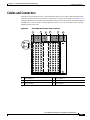
Cables and Connectors
External network connections to the 8-port E3/DS3 ATM line card are made through the BNC connectors
mounted on the rear of the Cisco 10000 chassis, using 75-ohm coaxial cable. The approved cables for use
with the 8-port E3/DS3 ATM line card are cables conforming to WECO standards 728A, 734A, or 734D.
Use cable lengths up to 450 ft (137.16 m). 735A cables can be used with lengths up to 225 ft (68.58 m).
Cisco 10000 Series Routers Line Card Hardware Installation Guide
2-6
OL-6773-04
Chapter 2
8-Port E3/DS3 ATM Line Card Overview
Cables and Connectors
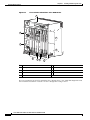
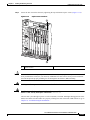
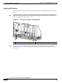
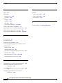
Figure 2-4
Cisco 10000 Chassis Rear—BNC Connectors
1
Tx
2
Tx
0
RX
4
3
0
0
6
Tx
RX
RX
Tx
1
1
Tx
RX
RX
Tx
2
2
7
Tx
RX
RX
Tx
3
3
Tx
RX
RX
Tx
4
4
Tx
RX
RX
Tx
5
5
Tx
RX
RX
Tx
6
6
8
Tx
RX
RX
Tx
7
7
Tx
RX
126111
RX
5
1
Line card slot 8
5
Line card slot 1
2
Line card slot 5
6
Power supply
3
Blower module
7
Half-height line card subslot 0
4
Line card slot 4
8
Half-height line card subslot 1
The BNC connectors on the rear of the chassis, which use coaxial cable, are used with the 8-port E3/DS3
ATM line card.
Cisco 10000 Series Routers Line Card Hardware Installation Guide
OL-6773-04
2-7
Chapter 2
8-Port E3/DS3 ATM Line Card Overview
Cables and Connectors
Figure 2-5
Cisco 10005 Chassis Rear—BNC Connectors
2
3
RX
RX
1
RX
RX
RX
TX
TX
TX
TX
TX
RX
TX
RX
TX
RX
TX
RX
TX
RX
TX
TX
RX
RX
TX
RX
RX
TX
RX
RX
TX
RX
RX
TX
RX
TX
TX
TX
TX
TX
RX
RX
RX
RX
RX
TX
TX
TX
TX
TX
RX
RX
RX
RX
RX
MINOR
ALARM
TX
TX
TX
TX
TX
RX
RX
RX
RX
RX
TX
RX
TX
RX
TX
RX
TX
RX
TX
RX
MAJOR
ALARM
EXT
CLOCK
A+
AB+
B-
NO
CO
NC
NO
CO
NC
NO
CO
NC
CRITICAL
ALARM
RX
TX
TX
TX
TX
TX
60 VDC
1A MAX
100-240V
50/60 HZ
15-7A
CAUTIO
THIS UNIT
N
SUPPLY HAS MORE
THAN
POWER CORD. DISCON
ONE
SERVIC SUPPLY CORDSNECT TWOPOWER
ING TO
BEFOR (2)
AVOID
ELECTR E
IC SHOCK
.
132319
100-240V
50/60 HZ
15-7A
FAULT
POWER
FAULT
POWER
CAUTIO
THIS UNIT
N
SUPPLY HAS MORE
THAN
POWER CORD. DISCON
ONE
SERVIC SUPPLY CORDSNECT TWOPOWER
ING TO
BEFOR (2)
AVOID
ELECTR E
IC SHOCK
.
1
Line card slots 1 (top) to 5 (bottom)
2
Subslot 1/0 (top) to 5/0 (bottom)
3
Subslots 1/1 (top) to 5/1 (bottom)
Also see Appendix A, “Cisco 10005 Extender Card Information” for information about the extender card
which must be used with the 8-port Unchannelized E3/T3 line card in the Cisco 10005 chassis.
All Cisco 10005 ESR cards connect to a backplane in the center of the chassis, and require extender cards
to deliver the alarm, BITS clock, and DS3 signals to the rear of the chassis to make them accessible. The
Cisco 10005 ESR alarm extender card and T3/E3 extender card extend and terminate these signals.
Go to Chapter 16, “Preparing for Installation” to begin the installation or replacement of the line card.
For troubleshooting information, see Chapter 18, “Troubleshooting the Installation.”
Cisco 10000 Series Routers Line Card Hardware Installation Guide
2-8
OL-6773-04
C H A P T E R
3
1-Port OC-12 ATM Line Card Overview
This chapter describes the Cisco 10000 series 1-port OC-12 ATM line card (referred to as the 1-port
channelized OC-12 ATM line card), and contains the following sections:
•
Line Card Summary, page 3-1
•
Software and Hardware Compatibility, page 3-2
•
Line Card, Router, and Processor Compatibility, page 3-2
•
LEDs, page 3-3
•
Physical Specifications, page 3-4
•
Slot Locations, page 3-5
•
Cables and Connectors, page 3-6
Line Card Summary
Table 3-1
1-Port OC-12 ATM Line Card Summary
Product Number
ESR-1OC-12-ATM=
Description
Minimum Cisco IOS Release
1-port OC-12 ATM line card
Initial Cisco IOS releases for PRE-1:
12.0(22)S and later releases of Cisco IOS Release 12.0S
Initial Cisco IOS releases for PRE-2:
12.0(10)SL and later releases of 12.0SL
12.0(22)S and later releases of Cisco IOS Release 12.0S
12.2(28)SB and later releases of Cisco IOS Release 12.2(28)SB
12.3(7)XI and later releases of Cisco IOS 12.3XI
Initial Cisco IOS releases for PRE-3:
12.2(31)SB2 and later releases of 12.2SB
For registered Cisco.com users, use Software Advisor to
determine the software releases for this line card.
The 1-port OC-12 ATM line card is a trunk uplink for the Cisco 10000series routers that provides
IP packet routing over ATM virtual circuit connections using a single-mode fiber intermediate reach
SC connector.
Cisco 10000 Series Routers Line Card Hardware Installation Guide
OL-6773-04
3-1
Chapter 3
1-Port OC-12 ATM Line Card Overview
Software and Hardware Compatibility
The 1-port OC-12 ATM line card is a standard implementation of ATM over SONET switching and
supports the following features:
•
MPLS
•
ATM services
•
Alarm processing
•
Performance monitoring
If you are a registered Cisco.com user, see Feature Navigator for supported features.
Software and Hardware Compatibility
To check the minimum software requirements of Cisco IOS software with the hardware installed on your
router, Cisco maintains the Software Advisor tool on Cisco.com. This tool does not verify if line cards
within a system are compatible, but does provide the minimum Cisco IOS requirements for individual
hardware line cards, modules, or options.
Note
Access to this tool is limited to users with Cisco.com login accounts.
To access Software Advisor, click Login at Cisco.com, type “Software Advisor” in the SEARCH box,
and click Go. Click the link for the Software Advisor tool.
Choose a product family or enter a specific product number to search for the minimum supported
software release needed for your hardware.
Line Card, Router, and Processor Compatibility
Table 3-2 provides information about the router model, line card, and processor compatibility.
Table 3-2
Line Card, Router, and Processor Compatibility
Line Card
Cisco 10008
Cisco 10005
PRE-3
PRE-2
PRE-1
PRE
1-port OC-12 ATM line card
Yes
Yes
Yes
Yes
Yes
Yes
Cisco 10000 Series Routers Line Card Hardware Installation Guide
3-2
OL-6773-04
Chapter 3
1-Port OC-12 ATM Line Card Overview
LEDs
LEDs
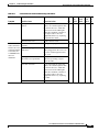
The 1-port OC-12 ATM line card LEDs are described in Figure 3-1.
1-Port OC-12 ATM Line Card Faceplate Description
CISCO
10000
1
2
4
3
OC–12/STM–4 ATM SM–IR
OP
RX
M
AR
TX
LO
L
I
FA
Tx
Rx
AL
5
LE
126715
Figure 3-1
R
IE
AB
RR
EN
CA
6
7
1
FAIL LED
5
TX LED
2
LOOP LED
6
ENABLE LED
3
ALARM LED
7
CARRIER LED
4
RX LED
Table 3-3 provides a description of the 1-port OC-12 ATM line card LEDs.
Table 3-3
LED Description
LED Label
Color
State
Meaning
FAIL
Yellow
Off
A major failure has disabled the line card.
On
On when the line card power-on self test (POST ) fails.
Off
Off when the line card is available for normal operation.
On
On when some portion of the corresponding port data is in
a loopback state and is not available for normal operations.
Off
No alarm condition.
On
Indicates an alarm condition at the OC-12 level.
On
The port is enabled for data traffic.
Off
The port is not enabled for data traffic.
On
The port is receiving traffic.
Off
The port is not receiving traffic.
On
The port is transmitting traffic.
Off
The port is not transmitting traffic.
On
On when a carrier is detected at the corresponding port.
Off
Off when a carrier is not detected.
LOOP
ALARM
ENABLE
RX
TX
CARRIER
(carrier
detected)
Yellow
Yellow
Green
Green
Green
Green
Cisco 10000 Series Routers Line Card Hardware Installation Guide
OL-6773-04
3-3
Chapter 3
1-Port OC-12 ATM Line Card Overview
Physical Specifications
Physical Specifications
The 1-port channelized OC-12 ATM line card physical specifications are shown in Table 3-4:
Table 3-4
1-Port Channelized OC-12 ATM Line Card Physical Specifications
Description
Specifications
Physical dimensions
Height: 16.0 in. (40.64 cm)
Depth: 9.97 in. (25.32 cm)
Width: 1.12 in. (2.83 cm)
Shipping weight
Approximately 4.75 lb (2.16 kg)
Operating temperature
41oF to 104oF (5oC to 40oC)
Short-term operating temperature is limited to
131oF (55oC) in compliance with Bellcore GR
Relative humidity
Operating—nominal: 5% to 85%
Operating—short term: 5% to 90%
Storage: 5% to 95%
Storage temperature
–40oF to 158oF (–40oC to 70C o)
Cisco 10000 Series Routers Line Card Hardware Installation Guide
3-4
OL-6773-04
Chapter 3
1-Port OC-12 ATM Line Card Overview
Slot Locations
Slot Locations
The line card slot designations are shown in this section. See Figure 3-2 for line card slot designations
for the Cisco 10008 router and Figure 3-3 for line card slot designations for the Cisco 10005 router.
Figure 3-2
Line Card Slot Designations for the Cisco 10008 Router
1
FANS
OK
FAN
FAILURE
MULTIFAN
FAILURE
When hot CAUTION
removal swapping
this fan
be done and replaceme
tray,
system in under two nt must
shutdown
minu
will occutes or
r.
1
2
CISCO
10000
3
FA
CISCO
10000
4
0A
PROC
ESSO
0B
R ONLY
C10
CISC
000
O
1000
6CT30
IL
FA
IL
FA
IL
FA
IL
CISCO
10000
CISCO
10000
5
CISCO
10000
6
C10
CISC
000
O
1000
6CT30
FAIL
7
FA
C10
CISC
000
O
1000
6CT30
N
O
O
LE
FAIL
X
OP
M
AR
R
IE
LO
AL
OP
RR
M
AR
R
IE
LO
CA
AL
RR
O
AU
AU
X
M
0 0 CA ALARLOOP
PORT
AC
TI
IT
OP
M
AR
R
IE
LO
AL
M
0 0 CA ALARLOOP
PORT
RR
T
M
0 0 CA ALARLOOP
PORT
Y
VIT
K
N
TI
Y
LI
AC
VIT
K
N
TI
LI
AC
K
M
0 0 CA ALARLOOP
PORT
CA
E
OP
N
M
AR
R
IE
R
LO
E
N
AL
T
LI
1 1
PORT
Y
TH
E
K
RR
E
N
N
IT
CA
LI
OP
LO
M
AR
R
IE
V
R
AL
TI
E
1
RR
AC
Y
TH
CA
V
E
2
1 1
PORT
ALARMS
PORT
2 2
1 1
PORT
1 1
PORT
ALARMS
C
POWER
R
IT
R
PORT
2 2
IN
AJO
AL
M
IC
R
M
PORT
2 2
IN
R
M
R
O
O
O
R
AC
4
PORT
2 2
IT
AL
AJO
M
OP
R
IE
AR
LO
RX
AL
TX
RR
NK
CA
PORT
3 3
C
IC
M
3
LI
FAULT
MISWIR
E
FAIL
S
IL
CA
N
0
FA
FAIL
C
LE
IL
S
2
CISCO
10000
FA
IL
O
8
C10
CISC
000
O
1000
6CT30
FA
IL
C
PORT
3 3
AC
PORT
3 3
O
PORT
4 4
PORT
3 3
CA
5
RR
PORT
4 4
PORT
5 5
RX
R
PORT
4 4
TX
IE
PORT
4 4
PORT
5 5
PORT
5 5
PORT
5 5
T
SLO
T
SLO
0
0
S
TU IL
STA FA
3
S
TU IL
STA FA
BIT
S
BIT
S
6XCT3–DS0
OC–12/STM–4 POS SM–IR
6XCT3–DS0
6XCT3–DS0
P/N ESR-PRE3
P/N ESR-PRE3
PERFORMANCE ROUTING ENGINE
PERFORMANCE ROUTING ENGINE
6XCT3–DS0
6XCT3–DS0
CH OC-12-DSO SM-IR
GIGABIT ETHERNET
POWER
FAULT
MISWIR
E
PROC
ESSO
4
132515
R ONLY
5
6
7
1
Blower module
5
PRE slot 0A
2
Primary PEM
6
PRE slot 0B
3
Redundant PEM
7
Line card slots 5 to 8
4
Line card slots 1 to 4
The 1-port OC-12 ATM line card can be installed in line card slot 1 through slot 8.
Cisco 10000 Series Routers Line Card Hardware Installation Guide
OL-6773-04
3-5
Chapter 3
1-Port OC-12 ATM Line Card Overview
Cables and Connectors
Figure 3-3
Line Card Slot Designations for the Cisco 10005 Router
4
CISCO
10000
CISCO
10000
5
FAIL
FAIL
RX
CISCO
10000
FAIL
CISCO
10000
FAIL
CISCO
10000
3
TX
OC-12/STM
IER
-4 POS
RR
CA
FAIL
SM-IR
RX
TX
OC-12/STM
IER
-4 POS
RR
CA
SM-IR
OP
LO
M
ALAR
IER
RR
2
1
0
CA
6XCT3–DS
5
4
3
0
OP
LO
M
ALAR
IER
RR
2
1
0
CA
6XCT3–DS
5
4
3
0
OP
LO
TY
HER
LIN NET
K
AC
TIVI
AU
X
LE
M
ALAR
LE
AB
EN
SLOT
-4 ATM
ANCE
0
ROUTING
SM-IR
ENGINE
US
132318
ST
AT
FA
IL
O
OR
AC
CR
ITIC
AL
MAJ
MIN
OR
PERFORM
US
ENGINE
IL
ST
AT
O
OR
AC
CR
ITIC
AL
ROUTING
FA
ANCE
1
0
MAJ
SLOT
SLOT
MIN
OR
AU
X
TY
HER
LIN NET
K
AC
TIVI
ET
CO
NSO
CISCO
10000
OC-12/STM
PERFORM
1
LE
SLOT
1
TX
IER
RR
CA
ET
CO
NSO
CISCO
10000
2
RX
1
PRE slot A
4
Line card subslot 1/0 (top) to 5/0 (bottom)
2
PRE slot B
5
Subslots 1/1 (top) to 5/1 (bottom)
3
Line card slots 1 (top) to 5 (bottom)
The 1-port OC-12 ATM line card can be installed in line card slot 1 through slot 5.
Cables and Connectors
Table 3-5 provides optical cabling specifications for the line card.
Table 3-5
Optical Specifications
Transceiver Type
Single-mode
intermediate reach
Maximum
Power to
Receiver
Minimum
Receiver
Sensitivity
Nominal Distance
Between Stations
–15 dBm
minimum to
–8 dBm
maximum
–8 dBm
–28 dBm
Table 3-6
Optical Power Budget
Transmit
Power
Wavelength
Fiber Type
Up to 9 mi (15 km)
1280 nm to
1335 nm
Single mode,
core size 8 to 10
microns
Power Budget
Transmit Power
Receive Power
Typical Maximum Distance
12 dB
–15 to –8 dBm
–18 to –8 dBm
9.3 miles (15 km)
Go to Chapter 16, “Preparing for Installation” to begin the installation or replacement of the line card.
For troubleshooting information, see Chapter 18, “Troubleshooting the Installation.”
Cisco 10000 Series Routers Line Card Hardware Installation Guide
3-6
OL-6773-04
PA R T
2
Channelized Line Cards
C H A P T E R
4
4-Port Channelized T3 Half-Height Line Card
Overview
This chapter describes the Cisco 10000 series 4-port channelized T3 half-height line card (referred to as
the 4-port channelized T3 half-height line card), and contains the following sections:
•
Line Card Summary, page 4-1
•
Software and Hardware Compatibility, page 4-2
•
Line Card, Router, and Processor Compatibility, page 4-2
•
LEDs, page 4-3
•
Physical Specifications, page 4-4
•
Slot Locations, page 4-5
•
Cables and Connectors, page 4-6
Line Card Summary
Table 4-1
4-Port Channelized T3 Half-Height Line Card Summary
Product Number
Description
Minimum Cisco IOS Release
ESR-HH-4CT3=
Half-height line card for the Cisco 10000 series
router. It provides four ports of channelized
T3 service at full line rate.
12.2(28)SB and later releases of
Cisco IOS Release 12.2(28)SB
ESR-HH-CARRIER= Full-length base carrier for half-slot line card
12.O(23)S and later releases of
Cisco IOS Release 12.OS
ESR-HH-COVER=
Blank filler for half-height line cards
—
CAB-BNC-7INY=
Optional Y-cable
12.2(28)SB and later releases of
Cisco IOS Release 12.2(28)SB
For registered Cisco.com users, use Software
Advisor to determine the software releases for
this line card.
Cisco 10000 Series Routers Line Card Hardware Installation Guide
OL-6773-04
4-1
Chapter 4
4-Port Channelized T3 Half-Height Line Card Overview
Software and Hardware Compatibility
The 4-port channelized T3 half-height line card provides the Cisco 10000 router with four DS3 ports of
high-density T3 service. The 4-port channelized T3 half-height line card provides the following features:
•
Supports full line rate transfers of packet sizes from 64 bytes to 8000 bytes
•
Supports 256 serial data channels for the first three ports, and 255 serial data channels for the last
port, or 1023 channels per half-height module
•
The 256 (255) serial data channels per port are configurable up to:
– 1 DS3 interface
– 28 DS1 interfaces
– 256 (255) N x DS0 interfaces
Or any combination of these interfaces that does not exceed the bandwidth of the port
Note
•
Port 3 supports only 255 channels.
Provides high availability when two 4-port channelized T3 half-height line cards are installed and
interconnected with a Y-cable in a redundant configuration
The 4-port channelized T3 half-height line card conforms to USA and international interface standards
for DS3 operation. Among these are ANSI T1.107, ANSI T1.102, ANSI T1.404, ITU G.703, and
ITU G.704.
If you are a registered Cisco.com user, see Feature Navigator for supported features.
Software and Hardware Compatibility
To check the minimum software requirements of Cisco IOS software with the hardware installed on your
router, Cisco maintains the Software Advisor tool on Cisco.com. This tool does not verify whether line
cards within a system are compatible, but does provide the minimum Cisco IOS requirements for
individual hardware line cards, modules, or options.
Note
Access to this tool is limited to users with Cisco.com login accounts.
To access Software Advisor, click Login at Cisco.com, type “Software Advisor” in the SEARCH box,
and click Go. Click the link for the Software Advisor tool.
Choose a product family or enter a specific product number to search for the minimum supported
software release needed for your hardware.
Line Card, Router, and Processor Compatibility
Table 4-2 provides information about the router model, line card, and processor compatibility.
Table 4-2
Line Card, Router, and Processor Compatibility
Line Card
Cisco 10008
Cisco 10005
PRE-2
PRE-1
PRE
4-port channelized T3 half-height line card
Yes
No
Yes
No
No
Cisco 10000 Series Routers Line Card Hardware Installation Guide
4-2
OL-6773-04
Chapter 4
4-Port Channelized T3 Half-Height Line Card Overview
LEDs
LEDs
The 4-port channelized T3 half-height line card LEDs are described in Figure 4-1.
Figure 4-1
4-Port Channelized T3 Half-Height Line Card Faceplate Description
OP
LO M
AR
L
A RR
CA
L
I
FA
T1
T3
0
T1
T3
1
T1
T3
2
119998
CISCO
10000
1
T1
T3
3
2
3
4
1
FAIL LED
3
ALARM LED
2
LOOP LED
4
CARR (carrier detected) LED
Table Table 4-3 provides a description of the 4-port channelized T3 half-height line card LEDs.
Table 4-3
LED Description
LED Label
Color
State
Meaning
FAIL
Yellow
Off
Off when the line card is working properly. Turns on
for a few seconds during line card power-on self test
(POST), then turns off when the line card is working
properly.
On
On when the line card POST fails.
Off
Off when the port is available for normal operation.
On: T3 Level
On when a loopback has been configured at the T3 level,
and the port is not available for normal operation.
Blinking: T3 Level
In a redundant pair, the standby line card T3 level
LOOP LED blinks.
On: T1 Level
On when a loopback has been configured for any one of
the 28 T1s contained in the DS3 signal.
Off
Off when the port is operating normally.
On: T3 Level
On when a T3 level alarm condition exists on the
corresponding port.
On : T1 Level
On when an alarm condition exists on any one of the
28 T1s contained in the DS3 signal.
On
On when a carrier is detected at the corresponding
port.
Off
Off when a loss of signal (LoS) is indicated.
LOOP
ALARM1
CARR
(carrier
detected)
Yellow
Yellow
Green
1. See the “Channelized Line Cards Troubleshooting Information” section on page 18-6 for alarm information.
Cisco 10000 Series Routers Line Card Hardware Installation Guide
OL-6773-04
4-3
Chapter 4
4-Port Channelized T3 Half-Height Line Card Overview
Physical Specifications
Physical Specifications
The 4-port channelized T3 half-height line card physical specifications are shown in Table 4-4.
Table 4-4
4-Port Channelized T3 Half-Height Line Card Physical Specifications
Description
Specifications
Physical dimensions
Height: 7.8 in. (19.8 cm)
Depth: 11 i.n (27.9 cm)
Width: 1.3 in. (3.3 cm)
Shipping weight
Approximately 2 lbs (0.9 kg)
Operating temperature
41oF to 104oF (5oC to 40oC)
Short-term operating temperature is limited to 131oF (55oC) in
compliance with Bellcore GR
Relative humidity
Operating—nominal: 5% to 85%
Operating—short term: 5% to 90%
Storage: 5% to 95%
Storage temperature
–40oF to 158oF (–40oC to 70Co)
Cisco 10000 Series Routers Line Card Hardware Installation Guide
4-4
OL-6773-04
Chapter 4
4-Port Channelized T3 Half-Height Line Card Overview
Slot Locations
Slot Locations
The line card slot designations are shown in Figure 4-2.
Figure 4-2
Line Card Slot and Subslot Designations for the Cisco 10008 Router
1
FANS
OK
FAN
FAILURE
MULTIFAN
FAILURE
When hot CAUTION
removal swapping
this fan
be done and replaceme
tray,
system in under two nt must
shutdown
minu
will occutes or
r.
1
2
CISCO
10000
3
FA
CISCO
10000
4
0A
PROC
ESSO
0B
R ONLY
C10
CISC
000
O
1000
6CT30
CISCO
10000
IL
FA
IL
FA
IL
FA
IL
CISCO
10000
5
CISCO
CISC
O
10000
1000
0
6
C10
CISC
000
O
1000
6CT30
FAIL
7
N
S
O
O
OP
LO
M
AR
AL R
IE
RR
CA
N
FAIL
S
O
OP
LO
M
AR
AL R
IE
RR
CA
0
LE
AU
FAIL
X
AU
X
M
0 0 CA ALARLOOP
PORT
AC
TI
IT
OP
M
AR
R
IE
LO
AL
M
0 0 CA ALARLOOP
PORT
RR
CA
OP
M
AR
R
IE
1 1
PORT
PORT
2 2
LO
T
2
M
0 0 CA ALARLOOP
PORT
AL
K
E
OP
N
RR
M
AR
R
IE
R
N
1
OT
0
OT
SL
SL
E
LI
LO
T
CA
Y
TH
E
AL
IT
E
N
K
RR
V
R
N
1
OT
0
OT
1 1
PORT
TI
E
LI
SL
SL
1
AC
Y
TH
CA
V
E
M
0 0 CA ALARLOOP
PORT
1 1
PORT
POWER
1 1
PORT
3
PORT
2 2
PORT
2 2
M
OP
R
IE
AR
8
PORT
2 2
LO
RX
AL
TX
RR
NK
PORT
3 3
CA
LI
FAULT
MISWIR
E
IL
FA
FAIL
C
LE
2
CISCO
10000
IL
FA
O
8
C10
CISC
000
O
1000
6CT30
IL
FA
IL
FA
C10
CISC
000
O
1000
6CT30
C
4
PORT
3 3
PORT
4 4
PORT
3 3
PORT
3 3
CA
5
RR
PORT
4 4
PORT
5 5
RX
R
PORT
4 4
TX
IE
PORT
4 4
PORT
5 5
PORT
5 5
PORT
5 5
3
R
IT
A
L
A
JO
R
M
IN
O
R
AC
O
C
R
IT
IC
A
M
L
A
JO
R
M
IN
O
S
TA
TU
S
FA
6XCT3–DS0
6XCT3–DS0
R
6XCT3–DS0
FAULT
MISWIR
E
ALARMS
OC–12/STM–4 POS SM–IR
6XCT3–DS0
IC
M
PERFORMANCE ROUTING ENGINE
C
PERFORMANCE ROUTING ENGINE
O
6XCT3–DS0
CH OC-12-DSO SM-IR
GIGABIT ETHERNET
AC
POWER
9
S
TA
TU
IL
S
FA
126064
IL
PROC
ESSO
R ONLY
4
5
6
7
1
Blower module
6
PRE slot 0B
2
Primary PEM
7
Line card slots 5 to 8
3
Redundant PEM
8
Subslot 0
4
Line card slots 1 to 4
9
Subslot 1
5
PRE slot 0A
The 4-port channelized T3 half-height line card can be installed in subslot 0 or subslot 1 of line card slot 1
through slot 8. The Cisco 10000 carrier is used with the 4-port channelized T3 half-height line card.
Cisco 10000 Series Routers Line Card Hardware Installation Guide
OL-6773-04
4-5
Chapter 4
4-Port Channelized T3 Half-Height Line Card Overview
Cables and Connectors
Cables and Connectors
Figure 4-3 shows cable and connector information for the 4-port channelized T3 half-height line card.
Cables
External network connections to the 4-port channelized T3 half-height line card are made through the
BNC connectors mounted on the rear of the Cisco 10000 chassis, using 75-ohm coaxial cable. The
approved cables for use with the 4-port channelized T3 half-height line card are cables conforming to WECO
standards 728A, 734A, or 734D, for use with cable lengths up to 900 ft (274.32 m). 735A cables can be used
with lengths up to 225 ft (68.58 m).
Figure 4-3
Cisco 10000 Chassis Rear—BNC Connectors
1
Tx
2
Tx
0
RX
4
3
0
0
5
6
Tx
RX
RX
Tx
1
1
Tx
RX
RX
Tx
2
2
7
Tx
RX
RX
Tx
3
3
Tx
RX
RX
Tx
4
4
Tx
RX
RX
Tx
5
5
Tx
RX
RX
Tx
6
6
8
Tx
RX
RX
Tx
7
7
Tx
RX
126111
RX
1
Line card slot 8
5
Line card slot 1
2
Line card slot 5
6
Power supply
3
Blower module
7
Half-height line card subslot 0
4
Line card slot 4
8
Half-height line card subslot 1
The BNC connectors on the rear of the chassis, which use coaxial cable, are used with the 4-port
channelized T3 half-height line card.
Cisco 10000 Series Routers Line Card Hardware Installation Guide
4-6
OL-6773-04
Chapter 4
4-Port Channelized T3 Half-Height Line Card Overview
Cables and Connectors
Caution
Do not install Y-cables unless you are using the Y-cable redundancy feature and have read all of these
instructions.
Caution
The Y-cables must be installed before configuring redundancy, and removed before deconfiguring
redundancy.
•
Eight BNC ports are arranged vertically per line card slot.
•
Two BNC connectors, one TX and one RX, are used per port.
•
Two 4-port channelized T3 half-height line cards can be placed in one slot, using the Carrier, with
four BNC ports allocated for each 4-port channelized T3 half-height line card.
•
When the 4-port channelized T3 half-height line card is in subslot 0 (the top subslot), the BNC
connectors in use are ports 0 through 3.
•
When the 4-port channelized T3 half-height line card is in subslot 1 (the bottom subslot), the BNC
connectors in use are ports 4 through 7.
Optional Y-Cables
Caution
Read all of the information in this section before installing a Y-cable for redundancy.
Figure 4-4 shows the Y-cable. Figure 4-5 shows Y-cable connections. The product number for the
optional Y-cable is CAB-BNC-71NY=.
Optional Y-Cable
126153
Figure 4-4
Cisco 10000 Series Routers Line Card Hardware Installation Guide
OL-6773-04
4-7
Chapter 4
4-Port Channelized T3 Half-Height Line Card Overview
Cables and Connectors
Optional Y-Cable Connections
Tx
0
0
Tx
RX
RX
Tx
1
1
Tx
RX
RX
Tx
2
2
Tx
RX
RX
Tx
3
3
Tx
RX
RX
Tx
4
4
Tx
RX
RX
Tx
5
5
Tx
RX
RX
Tx
6
6
Tx
RX
RX
Tx
7
RX
7
Tx
RX
126154
Figure 4-5
The optional Y-cables can be used to provide one-to-one line card redundancy. For Y-cable redundant
applications, see the “Configuration Summary” section on page 4-9, and configure the hardware as follows:
•
Two 4-port channelized T3 half-height line cards must share the same slot.
•
Eight Y-cables are required to configure a redundant pair of 4-port channelized T3 half-height line
cards.
•
The Y-cable has three BNC connectors. The two similar connectors must be connected to BNC
connectors on the Cisco 10000 series router backplane corresponding to similar functions on each line
card (for example, RX to RX), with the remaining connector being connected to the cable from the
customer’s network. See Figure 4-5. The following text explains how the Y-cable connects two 4-port
channelized T3 half-height line cards. Additional Y-cables can be used as required.
– The Y-cable connects the 4-port channelized T3 half-height line card in subslot 0, port 0 RX to
the 4-port channelized T3 half-height line card in subslot 1, port 0 RX.
– Another Y-cable would connect to the 4-port channelized T3 half-height line card in subslot 0,
port 0 TX to the 4-port channelized T3 half-height line card in subslot 1, port 0 TX.
– The remaining six Y-cables are connected in a similar fashion to form a completely redundant
configuration.
Cisco 10000 Series Routers Line Card Hardware Installation Guide
4-8
OL-6773-04
Chapter 4
4-Port Channelized T3 Half-Height Line Card Overview
Cables and Connectors
Configuration Summary
Caution
The Y-cables must be installed before configuring redundancy, and removed before deconfiguring
redundancy.
1.
To configure redundancy, you must:
a. Attach all Y-cables in this order: to the primary line card, to the secondary line card, and to the
far end.
b. Configure the primary line card.
c. Configure the secondary line card.
2.
To deconfigure redundancy:
a. Use “red line switch from...” to make the secondary line card standby (if it is active) and the
primary line card active if you want to deconfigure only the secondary line card (perhaps for
servicing).
b. Detach the Y-cable from all ports on the secondary line card.
c. Deconfigure the secondary line card.
3.
If you want to deconfigure all redundancy, you must:
a. Remove all the Y-cables and the cable for nonredundancy if desired.
b. Deconfigure the secondary line card and primary line card.
See the Cisco 10000 Series Routers Line Card Configuration Guide for information about configuring
redundancy using the optional Y-cables.
Go to Chapter 16, “Preparing for Installation” to begin the installation or replacement of the line card.
For to rubles hooting information see Chapter 18, “Troubleshooting the Installation.”
Cisco 10000 Series Routers Line Card Hardware Installation Guide
OL-6773-04
4-9
Chapter 4
4-Port Channelized T3 Half-Height Line Card Overview
Cables and Connectors
Cisco 10000 Series Routers Line Card Hardware Installation Guide
4-10
OL-6773-04
C H A P T E R
5
24-Port Channelized E1/T1 Line Card Overview
This chapter describes the Cisco 10000 series 24-port channelized E1/T1 line card (referred to as the
24-port channelized E1/T1 line card), and contains the following sections:
•
Line Card Summary, page 5-1
•
Software and Hardware Compatibility, page 5-3
•
Line Card, Router, and Processor Compatibility, page 5-4
•
LEDs, page 5-4
•
Physical Specifications, page 5-5
•
Slot Locations, page 5-6
•
Cables, Connectors, and Pinouts, page 5-7
Line Card Summary
Table 5-1
24-Port Channelized E1/T1 Line Card Summary
Product Number
Description
Minimum Cisco IOS Release
ESR-24CT1/E1=
24-port channelized T1/E1 line card Initial Cisco IOS release for PRE-1:
12.0(22)S and later releases of Cisco IOS Release 12.0S
Initial Cisco IOS release for PRE-2:
12.2(15)BX and later releases of 12.2BX
2.2(28)SB and later releases of Cisco IOS Release 12.2(28)SB
12.3(7)XI and later releases of Cisco IOS 12.3XI
For registered Cisco.com users, use Software Advisor to
determine the software releases for this line card.
The 24-port channelized E1/T1 line card provides Cisco 10000 routers with 24 copper channelized or
unchannelized interface ports that you can configure as E1 or T1 interfaces. When you configure a line
card for:
•
E1 operation—You can configure each E1 port as one or more interfaces for framed (channelized)
operation, or as a single channel for unframed (unchannelized) operation.
•
T1 operation—You can configure each T1 port as one or more interfaces for framed operation.
Cisco 10000 Series Routers Line Card Hardware Installation Guide
OL-6773-04
5-1
Chapter 5
24-Port Channelized E1/T1 Line Card Overview
Line Card Summary
E1 Features
The E1 features of this line card support:
•
European 2.048 MbpsTU G.703 and G.704 serial interfaces
•
Local or network loopback for any E1 port. Network loopback supports:
– Line
– Payload
•
CRC4 (cyclic redundancy check) and non-CRC4 framing modes
•
Detection of LoS (loss of signal) and LoF (loss of frame)
•
Protocol encapsulations:
– High-Level Data Link Control (HDLC)
– Frame relay
– Point-to-Point Protocol (PPP)
•
Channel bandwidths of N x 64 kbps in framed E1 mode, where N has a value from 1 to 31, and a
single channel bandwidth of 2048 kbps (N = 32) in unframed E1 mode
•
Per-port selection of internal or external (line) clock source
•
Solutions for service providers where fiber interfaces are unavailable
•
Internet service provider interface connections to existing copper Internet Protocol (IP) E1 lines
•
Programmable National Reserved bits
•
High density bipolar 3 (HDB3) line encoding
•
E1-level bit error rate test (BERT) functions
T1 Features
The T1 features of this line card support:
•
Alternate Mark Inversion (AMI) or Bipolar with 8-Zeros Substitution (B8ZS) line encoding
•
Up to 24 separate interfaces per T1 port
•
FDL support:
– Full ANSI T1.403 mode
– ATT 54016 receive-only
– SMARTJACK remote loopback
•
Loopback for each T1 port
– Line and payload (types of network loopback)
– Local
– Remote
•
Per-port selection of internal or external (line) clock source
•
Detection of LoS and LoF
•
Short-haul line buildout up to 655 feet
Cisco 10000 Series Routers Line Card Hardware Installation Guide
5-2
OL-6773-04
Chapter 5
24-Port Channelized E1/T1 Line Card Overview
Software and Hardware Compatibility
•
Super Frame (SF) or Extended Super Frame (ESF) framing modes
•
Protocol encapsulations:
– HDLC
– Frame Relay
– PPP
•
Channel bandwidths of N x 64 kbps or N x 56 kbps in channelized T1 mode, where N has a value
from 1 to 24
•
Solutions for service providers where fiber interfaces are unavailable
•
Internet service provider interface connections to existing copper Internet Protocol (IP) T1 channels
•
T1-level bit error rate test (BERT) functions
If you are a registered Cisco.com user, see Feature Navigator for supported features.
Software and Hardware Compatibility
To check the minimum software requirements of Cisco IOS software with the hardware installed on your
router, Cisco maintains the Software Advisor tool on Cisco.com. This tool does not verify whether line
cards within a system are compatible, but does provide the minimum Cisco IOS requirements for
individual hardware line cards, modules, or options.
Note
Access to this tool is limited to users with Cisco.com login accounts.
To access Software Advisor, click Login at Cisco.com, type Software Advisor in the search box, and
click Go. Click the link for the Software Advisor tool.
Choose a product family or enter a specific product number to search for the minimum supported
software release needed for your hardware.
Cisco 10000 Series Routers Line Card Hardware Installation Guide
OL-6773-04
5-3
Chapter 5
24-Port Channelized E1/T1 Line Card Overview
Line Card, Router, and Processor Compatibility
Line Card, Router, and Processor Compatibility
Table 5-2 lists router model, line card, and processor compatibility.
Table 5-2
Line Card, Router, and Processor Compatibility
Line Card
Cisco 10008
Cisco 10005
PRE-2
PRE-1
PRE
24-port channelized E1/T1 line card
Yes
Yes
Yes
Yes
No
LEDs
The 24-port channelized E1/T1 line card LEDs are shown in Figure 5-1.
7
6
13
69414
10
12
10
12
22
0
1
22 23
L
I
FA
9
24XCHT1/E1-DS0
11
1
CISCO
10000
5
4
3
23
1
24-Port Channelized E1/T1 Line Card Faceplate Description
11
13
Figure 5-1
2
8
1
Top captive screw
6
Ports 0 to 11 status LEDs
2
Top ejector lever
7
Ports 12 to 23 status LEDs
3
FAIL LED
8
Bottom ejector lever
4
Ports 0 to 11 RJ-45 jacks
9
Bottom captive screw
5
Ports 12 to 23 RJ-45 jacks
Cisco 10000 Series Routers Line Card Hardware Installation Guide
5-4
OL-6773-04
Chapter 5
24-Port Channelized E1/T1 Line Card Overview
Physical Specifications
Table 5-3 provides a description of the 24-port channelized E1/T1 line card LEDs.
Table 5-3
LED Description
LED Label
Color
State
Meaning
FAIL
Yellow
Off
Off during normal operation. This LED lights
momentarily during power-on self test (POST) and
then goes out on a properly working line card.
On
On if a line card fails during operation, and an alarm
event occurs.
On
Carrier Detect LED on indicates that a carrier signal
exits at the corresponding port, which is normal
interface operation. During loopback testing, this
LED also lights green.
Off
When the LED is off, the port is administratively
down.
Off
When this Alarm Active LED is not lit, the port is
administratively down.
On
Alarm Active LED is on when the corresponding port
data path is in an alarm condition. The following
alarms are monitored: LoS (Loss of Signal), LoF
(Loss of Frame), RAI (Remote Alarm Indication),
and AIS (Alarm Indication Signal).
0–23 (Status LEDs)
Green
Yellow
Physical Specifications
The 24-port channelized E1/T1 line card physical specifications are shown in Table 5-4.
Table 5-4
24-Port Channelized E1/T1 Line Card Physical Specifications
Description
Specifications
Physical dimensions
Height: 16.0 in. (40.64 cm)
Depth: 9.97 in. (25.32 cm)
Width: 1.12 in. (2.83 cm)
Shipping weight
Approximately 4.75 lb (2.16 kg)
Operating temperature
41oF to 104oF (5oC to 40oC)
Short-term operating temperature is limited to
131oF (55oC) in compliance with Bellcore GR
Relative humidity
Operating—nominal: 5% to 85%
Operating—short term: 5% to 90%
Storage: 5% to 95%
Storage temperature
–40oF to 158oF (–40oC to 70C o)
Cisco 10000 Series Routers Line Card Hardware Installation Guide
OL-6773-04
5-5
Chapter 5
24-Port Channelized E1/T1 Line Card Overview
Slot Locations
Slot Locations
The line card slot designations are shown in this section. See Figure 5-2 for line card slot designations
for the Cisco 10008 router and Figure 5-3 for line card slot designations for the Cisco 10005 router.
Figure 5-2
Line Card Slot Designations for the Cisco 10008 Router
1
FANS
OK
FAN
FAILURE
MULTIFAN
FAILURE
When hot CAUTION
removal swapping
this fan
be done and replaceme
tray,
system in under two nt must
shutdown
minu
will occutes or
r.
1
2
CISCO
10000
3
FA
CISCO
10000
4
0A
PROC
ESSO
0B
R ONLY
C10
CISC
000
O
1000
6CT30
IL
FA
IL
FA
IL
FA
IL
CISCO
10000
CISCO
10000
5
CISCO
10000
6
C10
CISC
000
O
1000
6CT30
FAIL
7
N
O
O
CA
LE
FAIL
X
OP
M
AR
R
IE
LO
AL
RR
OP
M
AR
R
IE
LO
AL
RR
O
AU
AU
X
M
0 0 CA ALARLOOP
PORT
AC
TI
IT
OP
M
AR
R
IE
LO
AL
M
0 0 CA ALARLOOP
PORT
RR
OP
M
AR
R
IE
LO
T
M
0 0 CA ALARLOOP
PORT
TI
AC
Y
VIT
K
N
Y
LI
VIT
K
N
TI
LI
AC
K
M
0 0 CA ALARLOOP
PORT
CA
E
AL
N
RR
R
CA
E
N
OP
T
LI
1 1
PORT
Y
TH
E
K
IT
E
N
N
M
AR
R
IE
LI
LO
V
R
AL
TI
E
1
RR
AC
Y
TH
CA
V
E
2
1 1
PORT
ALARMS
PORT
2 2
1 1
PORT
1 1
PORT
ALARMS
C
POWER
R
IT
R
PORT
2 2
AJO
AL
M
IC
IN
PORT
2 2
IN
R
M
R
O
O
O
R
AC
4
PORT
2 2
IT
M
R
M
OP
R
IE
AR
LO
RX
AL
TX
RR
NK
CA
PORT
3 3
C
AJO
AL
M
IC
3
LI
FAULT
MISWIR
E
FAIL
S
IL
CA
N
0
FA
FAIL
C
LE
IL
S
2
CISCO
10000
FA
O
8
C10
CISC
000
O
1000
6CT30
IL
FA
IL
FA
C10
CISC
000
O
1000
6CT30
C
PORT
3 3
AC
PORT
3 3
O
PORT
4 4
PORT
3 3
CA
5
RR
PORT
4 4
PORT
5 5
RX
R
PORT
4 4
TX
IE
PORT
4 4
PORT
5 5
PORT
5 5
PORT
5 5
T
SLO
T
SLO
0
0
S
TU IL
STA FA
3
S
TU IL
STA FA
BIT
S
BIT
S
6XCT3–DS0
OC–12/STM–4 POS SM–IR
6XCT3–DS0
6XCT3–DS0
P/N ESR-PRE3
P/N ESR-PRE3
PERFORMANCE ROUTING ENGINE
PERFORMANCE ROUTING ENGINE
6XCT3–DS0
6XCT3–DS0
CH OC-12-DSO SM-IR
GIGABIT ETHERNET
POWER
FAULT
MISWIR
E
PROC
ESSO
4
132515
R ONLY
5
6
7
1
Blower module
5
PRE slot 0A
2
Primary PEM
6
PRE slot 0B
3
Redundant PEM
7
Line card slots 5 to 8
4
Line card slots 1 to 4
The 24-port channelized E1/T1 line card can be installed in line card slot 1 through slot 8.
Cisco 10000 Series Routers Line Card Hardware Installation Guide
5-6
OL-6773-04
Chapter 5
24-Port Channelized E1/T1 Line Card Overview
Cables, Connectors, and Pinouts
CISCO
10000
Line Card Slot Designations for the Cisco 10005 Router
FAIL
CISCO
10000
Figure 5-3
FAIL
RX
CISCO
10000
FAIL
CISCO
10000
FAIL
CISCO
10000
3
TX
OC-12/STM
IER
-4 POS
RR
CA
FAIL
SM-IR
RX
TX
OC-12/STM
IER
-4 POS
RR
CA
SM-IR
OP
LO
M
ALAR
IER
RR
2
1
0
CA
6XCT3–DS
5
4
3
0
OP
LO
M
ALAR
IER
RR
2
1
0
CA
6XCT3–DS
5
4
3
0
OP
TY
X
AU
AC
TIVI
SLOT
OC-12/STM
-4 ATM
SM-IR
PERFORM
ANCE
1
0
ROUTING
ENGINE
US
132516
ST
AT
FA
IL
O
OR
AC
CR
ITIC
AL
MAJ
MIN
OR
PERFORM
ENGINE
FA
IL
O
OR
AC
CR
ITIC
AL
ROUTING
ST
AT
US
ANCE
1
0
MAJ
SLOT
SLOT
MIN
OR
AU
X
TY
ET
AC
TIVI
HER
LIN NET
K
LE
CO
NSO
CISCO
10000
TX
IER
RR
CA
ET
HER
LIN NET
K
EN
SLOT
1
RX
M
ALAR
LE
AB
LE
CO
NSO
2
CISCO
10000
LO
1
PRE slot A
2
PRE slot B
3
Line card slots 1 (top) to 5 (bottom)
The 24-port channelized E1/T1 line card can be installed in line card slot 1 through slot 5.
Cables, Connectors, and Pinouts
You can use up to 24 Category 3 or Category 5 unshielded twisted pair (UTP) transmit and receive cables
with RJ-45 connectors at each end. These cables connect to two staggered 12-line faceplate RJ-45 jacks
with 110-ohm balanced-line inputs, which allow the line card to operate in either T1 (100 ohm balanced)
or E1 (120 ohm balanced) mode. The faceplate RJ-45 jacks are numbered 0 to 11 and 12 to 23
left-to-right and top-to-bottom.
You can also use a Cisco cable adapter (CAB-ADAPT-75-120=) for coaxial British Navel Connector
(BNC) unbalanced transmit and receive E1 connections (see the “Using the BNC Cable Adapter” section
on page 5-8).
Caution
If the Cisco 10000 series router is used in an environment in which lightning-induced transients are
likely to couple to the signal lines, use of shielded interconnection cables for the E1/T1 ports is highly
recommended. In addition, use of shielded interconnection cables for the E1/T1 ports is required to meet
Telcordia (formerly Bellcore) GR1089 CORE Section 4.5.9 and ETSI Section 5.2.2.2 (intrabuilding
lightning surge).
Cisco 10000 Series Routers Line Card Hardware Installation Guide
OL-6773-04
5-7
Chapter 5
24-Port Channelized E1/T1 Line Card Overview
Cables, Connectors, and Pinouts
Using the BNC Cable Adapter
Figure 5-4 shows the adapter cable available for the 24-port channelized E1/T1 line card.
L
I
FA
10
11
2
1
Faceplate, Connecting Cable, and Adapter Cable
CISCO
10000
Figure 5-4
1
3
RCV
126772
DISCO
CONNNECT NNNE12CT XMIT SHIEL
D
XMIT SHIEL
D TO GND 12 TO GND 12
XMIT
RJ-48c
1
Adapter cable
2
RJ-45 ports on faceplate
3
Connecting cable (RJ-45 STP, male/male)
An RJ-45 STP cable with two male RJ-45 connectors is required to connect the adapter cable and
RJ-45 ports on the face of the line card (Figure 5-5).
Figure 5-5
75–120 Ohm Adapter Cable
2
DISCONNECT XMIT SHIELD TO GND 1 2
D TO
HIEL
T XM
IT S
12
NEC
CON
DISC
ONN
ECT
XMI
T SH
IELD
GND
TO G
12
ND 1
XMIT
CONNECT XMIT SHIELD TO GND 1 2
RCV
45561
1 2
RJ-48c
Cisco cable adapters (CAB-ADAPT-75-120=) connect 75-ohm unbalanced G.703 E1 coaxial BNC
transmit and receive lines to Cisco E1 120-ohm balanced transmit and receive lines.
The connections are made through eight-pin RJ-45 jacks on the 120-ohm side of the adapter cable and
dual coaxial lines (transmit and receive) with BNC connectors at the 75-ohm side.
Cisco 10000 Series Routers Line Card Hardware Installation Guide
5-8
OL-6773-04
Chapter 5
24-Port Channelized E1/T1 Line Card Overview
Cables, Connectors, and Pinouts
Class A emissions compliance is met when the 120-ohm E1 port is connected to the 75-120-ohm cable
adapter using RJ-45 connectors and Category 3 or Category 5 shielded foil twisted-pair (FTP) cable with
120-ohm impedance. Two switches on the 120-ohm side must be configured to connect the outer
conductor of the shielded cable to a protected earth ground (see enlargement in Figure 5-5).
Pinouts
Table 5-5 lists pinouts for the RJ-45 connector.
Table 5-5
RJ-45 Port Pinouts
Pin
RJ-45
1
RX tip
2
RX ring
3
No connection
4
TX tip
5
TX ring
6
No connection
7
No connection
8
No connection
Go to Chapter 16, “Preparing for Installation” to begin the installation or replacement of the line card.
For troubleshooting information, see Chapter 18, “Troubleshooting the Installation.”
Cisco 10000 Series Routers Line Card Hardware Installation Guide
OL-6773-04
5-9
Chapter 5
24-Port Channelized E1/T1 Line Card Overview
Cables, Connectors, and Pinouts
Cisco 10000 Series Routers Line Card Hardware Installation Guide
5-10
OL-6773-04
C H A P T E R
6
1-Port Channelized OC-12/STM-4 Line Card
Overview
This chapter describes the Cisco 10000 series 1-port channelized OC-12/ STM-4 line card (referred to
as the 1-port channelized OC-12/STM-4 line card) and contains the following sections:
•
Line Card Summary, page 6-2
•
Software and Hardware Compatibility, page 6-3
•
Line Card, Router, and Processor Compatibility, page 6-3
•
LEDs, page 6-3
•
Physical Specifications, page 6-4
•
Slot Locations, page 6-5
•
Cables and Connectors, page 6-7
Cisco 10000 Series Routers Line Card Hardware Installation Guide
OL-6773-04
6-1
Chapter 6
1-Port Channelized OC-12/STM-4 Line Card Overview
Line Card Summary
Line Card Summary
Table 6-1
1-Port Channelized OC-12/STM-4 Line Card Summary
Product Number
Description
Minimum Cisco IOS Release
ESR-1COC-12/STM-4-SMI=
1-port channelized
OC-12/STM-4
(DS0/DS1/E1/DS3)
line card
Initial Cisco IOS releases for PRE-1:
12.0(9)SL and later releases of 12.0SL
12.0(17)ST and later releases of 12.0ST
12.0(22)S and later releases of Cisco IOS Release 12.0S
12.2(8)BZ and later releases of Cisco IOS Release 12.2(8)BZ
for SONET mode only.
For both SONET and SDH mode, use Cisco IOS Release
12.0(23)S and later releases of Cisco IOS 12.0S.
Initial Cisco IOS releases for PRE-2:
12.2(28)SB and later releases of Cisco IOS Release 12.2(28)SB
12.3(7)XI and later releases of Cisco IOS 12.3XI
For both SONET and SDH mode, use Cisco IOS
Release 12.2(15)BX and later releases of Cisco IOS 12.2BX
Initial Cisco IOS releases for PRE-3:
12.2(31)SB2 and later releases of Cisco IOS Release 12.2SB
For registered Cisco.com users, use Software Advisor to
determine the software releases for this line card.
The 1-port channelized OC-12/STM-4 line card uses fractional T1 (n x DS0), DS-1, E1, fractional E1
(n x DS0) and DS3 IP services to connect ISP customers to the network backbone. It provides full duplex
operation at OC-12 bandwidth rates using a (single-mode) fiber optic port that provides the Cisco 10000
series router with a single interface that connects up to 768 individual channelized options.
The 1-port channelized OC-12/STM-4 line card has one single-mode, intermediate-reach
SC OC-12/STM-4 duplex optical connector.
The line card can be configured into either SONET or SDH mode.
•
When configured for SONET mode, the OC-12 port carries twelve DS3 (full rate, subrate, or
channalized down to DS1) channels, or 336 individual DS1, each capable of carrying one channel
at full or fractional rates.
•
When configured for SDH mode, the STM-4 port carries twelve DS3 (full rate, subrate, or
channalized) channels, 336 individual DS1s, or 252 individual E1s; each DS1/E1 is capable of
carrying a single channel at full or fractional rates. The line card runs in either E1 or T1 mode, but
no mixture of T1/E1 is supported.
The line card supports up to 768 channels. The total number of channels cannot exceed the chassis
scaling limits.
If you are a registered Cisco.com user, see Feature Navigator for supported features.
Cisco 10000 Series Routers Line Card Hardware Installation Guide
6-2
OL-6773-04
Chapter 6
1-Port Channelized OC-12/STM-4 Line Card Overview
Software and Hardware Compatibility
Software and Hardware Compatibility
To check the minimum software requirements of Cisco IOS software with the hardware installed on your
router, Cisco maintains the Software Advisor tool on Cisco.com. This tool does not verify whether line
cards within a system are compatible, but does provide the minimum Cisco IOS requirements for
individual hardware line cards, modules, or options.
Note
Access to this tool is limited to users with Cisco.com login accounts.
To access Software Advisor, click Login at Cisco.com, type “Software Advisor” in the SEARCH box,
and click Go. Click the link for the Software Advisor tool.
Choose a product family or enter a specific product number to search for the minimum supported
software release needed for your hardware.
Line Card, Router, and Processor Compatibility
Table 6-2 lists the router model, line card, and processor compatibility.
Table 6-2
Line Card, Router, and Processor Compatibility
Line Card
Cisco 10008
Cisco 10005
PRE-3
PRE-2
PRE-1
PRE
1-port channelized OC-12/ STM-4
Line Card
Yes
Yes
Yes
Yes
Yes
Yes
LEDs
The 1-port channelized OC-12/ STM-4 line card LEDs are shown in Figure 6-1.
Figure 6-1
1-Port Channelized OC-12/STM-4 Faceplate Description
2
3
4
ESR-ICOC12-SMI
OP
LO
L
I
FA
126714
CISCO
10000
1
M
AR
AL
R
IE
R
AR
C
5
6
1
Fail LED
4
Loop LED
2
TX
5
Alarm LED
3
RX
6
Carrier LED
Cisco 10000 Series Routers Line Card Hardware Installation Guide
OL-6773-04
6-3
Chapter 6
1-Port Channelized OC-12/STM-4 Line Card Overview
Physical Specifications
Table 6-3 provides a description of the 1-port channelized OC-12/ STM-4 line card LEDs.
Table 6-3
LED Description
LED Label
Color
State
Meaning
FAIL
Yellow
Off
On when the line card power on self test (POST) fails.
On
A major failure has disabled the line card.
Off
Port is not in a loopback state.
On
On when the port is in a loopback state and is not enabled for data
traffic.
Off
No alarm condition.
On
On when an alarm condition exists at OC-12, E-1, DS3, or
DS1 level.
Off
No carrier is detected; the port is not able to pass traffic.
On
On when a carrier is detected at the corresponding port.
LOOP
ALARM
CARRIER
(carrier
detected)
Yellow
Yellow
Green
Physical Specifications
The 1-port channelized OC-12/ STM-4 line card physical specifications are shown in Table 6-4.
Table 6-4
1- Port Channelized OC-12/STM-4 Line Card Physical Specifications
Description
Specifications
Physical dimensions
Height: 16.0 in. (40.64 cm)
Depth: 9.97 in. (25.32 cm)
Width: 1.12 in. (2.83 cm)
Shipping weight
Approximately 4.75 lb (2.16 kg)
Operating temperature
41oF to 104oF (5oC to 40oC)
Short-term operating temperature is limited to
131oF (55oC) in compliance with Bellcore GR
Relative humidity
Operating—nominal: 5% to 85%
Operating—short term: 5% to 90%
Storage: 5% to 95%
Storage temperature
–40oF to 158oF (–40oC to 70C o)
Cisco 10000 Series Routers Line Card Hardware Installation Guide
6-4
OL-6773-04
Chapter 6
1-Port Channelized OC-12/STM-4 Line Card Overview
Slot Locations
Slot Locations
The line card slot designations are shown in this section. See Figure 6-2 for line card slot designations
for the Cisco 10008 router and Figure 6-3 for line card slot designations for the Cisco 10005 router.
Figure 6-2
Line Card Slot Designations for the Cisco 10008 Router
1
FANS
OK
FAN
FAILURE
MULTIFAN
FAILURE
When hot CAUTION
removal swapping
this fan
be done and replaceme
tray,
system in under two nt must
shutdown
minu
will occutes or
r.
1
2
CISCO
10000
3
FA
CISCO
10000
4
0A
PROC
ESSO
0B
R ONLY
C10
CISC
000
O
1000
6CT30
IL
FA
IL
FA
IL
FA
IL
CISCO
10000
CISCO
10000
5
CISCO
10000
6
C10
CISC
000
O
1000
6CT30
FAIL
7
FA
C10
CISC
000
O
1000
6CT30
N
O
O
LE
FAIL
X
OP
M
AR
R
IE
LO
AL
OP
RR
M
AR
R
IE
LO
CA
AL
RR
O
AU
AU
X
M
0 0 CA ALARLOOP
PORT
AC
TI
IT
OP
M
AR
R
IE
LO
AL
M
0 0 CA ALARLOOP
PORT
RR
T
M
0 0 CA ALARLOOP
PORT
Y
VIT
K
N
TI
Y
LI
AC
VIT
K
N
TI
LI
AC
K
M
0 0 CA ALARLOOP
PORT
CA
E
OP
N
M
AR
R
IE
R
LO
E
N
AL
T
LI
1 1
PORT
Y
TH
E
K
RR
E
N
N
IT
CA
LI
OP
LO
M
AR
R
IE
V
R
AL
TI
E
1
RR
AC
Y
TH
CA
V
E
2
1 1
PORT
ALARMS
PORT
2 2
1 1
PORT
1 1
PORT
ALARMS
C
POWER
R
IT
R
PORT
2 2
IN
AJO
AL
M
IC
R
M
PORT
2 2
IN
R
M
R
O
O
O
R
AC
4
PORT
2 2
IT
AL
AJO
M
OP
R
IE
AR
LO
RX
AL
TX
RR
NK
CA
PORT
3 3
C
IC
M
3
LI
FAULT
MISWIR
E
FAIL
S
IL
CA
N
0
FA
FAIL
C
LE
IL
S
2
CISCO
10000
FA
IL
O
8
C10
CISC
000
O
1000
6CT30
FA
IL
C
PORT
3 3
AC
PORT
3 3
O
PORT
4 4
PORT
3 3
CA
5
RR
PORT
4 4
PORT
5 5
RX
R
PORT
4 4
TX
IE
PORT
4 4
PORT
5 5
PORT
5 5
PORT
5 5
T
SLO
T
SLO
0
0
S
TU IL
STA FA
3
S
TU IL
STA FA
BIT
S
BIT
S
6XCT3–DS0
OC–12/STM–4 POS SM–IR
6XCT3–DS0
6XCT3–DS0
P/N ESR-PRE3
P/N ESR-PRE3
PERFORMANCE ROUTING ENGINE
PERFORMANCE ROUTING ENGINE
6XCT3–DS0
6XCT3–DS0
CH OC-12-DSO SM-IR
GIGABIT ETHERNET
POWER
FAULT
MISWIR
E
PROC
ESSO
4
132515
R ONLY
5
6
7
1
Blower module
5
PRE slot 0A
2
Primary PEM
6
PRE slot 0B
3
Redundant PEM
7
Line card slots 5 to 8
4
Line card slots 1 to 4
The 1-port channelized OC-12/ STM-4 line card can be installed in line card slot 1 through slot 8.
Cisco 10000 Series Routers Line Card Hardware Installation Guide
OL-6773-04
6-5
Chapter 6
1-Port Channelized OC-12/STM-4 Line Card Overview
Slot Locations
CISCO
10000
Line Card Slot Designations for the Cisco 10005 Router
FAIL
CISCO
10000
Figure 6-3
FAIL
RX
CISCO
10000
FAIL
CISCO
10000
FAIL
CISCO
10000
3
TX
OC-12/STM
IER
-4 POS
RR
CA
FAIL
SM-IR
RX
TX
OC-12/STM
IER
-4 POS
RR
CA
SM-IR
OP
LO
M
ALAR
IER
RR
2
1
0
CA
6XCT3–DS
5
4
3
0
OP
LO
M
ALAR
IER
RR
2
1
0
CA
6XCT3–DS
5
4
3
0
OP
TY
HER
LIN NET
K
AC
TIVI
AU
X
LE
M
ALAR
LE
AB
EN
SLOT
TX
OC-12/STM
-4 ATM
IER
RR
CA
SM-IR
PERFORM
ANCE
1
ROUTING
ENGINE
2
PRE slot B
US
132516
ST
AT
FA
IL
O
AC
CR
ITIC
AL
OR
ENGINE
IL
ST
AT
US
ROUTING
FA
OR
CR
ITIC
AL
O
PRE slot A
MAJ
ANCE
AC
1
MIN
OR
PERFORM
1
0
MAJ
SLOT
SLOT
MIN
OR
AU
X
AC
TIVI
TY
HER
LIN NET
K
LE
0
ET
CO
NSO
CISCO
10000
SLOT
1
RX
ET
CO
NSO
2
CISCO
10000
LO
3
Line card slots 1 (top) to 5 (bottom)
The 1-port channelized OC-12/ STM-4 line card can be installed in line card slot 1 through slot 5.
Cisco 10000 Series Routers Line Card Hardware Installation Guide
6-6
OL-6773-04
Chapter 6
1-Port Channelized OC-12/STM-4 Line Card Overview
Cables and Connectors
Cables and Connectors
The 1-port channelized OC-12/STM-4 line card uses an SC-type optical connector.
Table 6-5 and Table 6-6 provide optical cabling specifications for the line card.
Table 6-5
Optical Specifications
Transceiver Type
Single-mode
intermediate reach
Maximum
Power to
Receiver
Minimum
Receiver
Sensitivity
Nominal Distance
Between Stations
–15 dBm
minimum to
–8 dBm
maximum
–8 dBm
–28 dBm
Up to 9 mi (15 km)
Table 6-6
Optical Power Budget
Transmit
Power
Wavelength
Fiber Type
1280 nm to
1335 nm
Single mode,
core size 8 to
10 microns
Power Budget
Transmit Power
Receive Power
Typical Maximum Distance
12 dB
–15 dBm to –8 dBm
–28 dBm to –8 dBm
9.3 miles (15 km)
Go to Chapter 16, “Preparing for Installation” to begin the installation or replacement of the line card.
For troubleshooting information, see Chapter 18, “Troubleshooting the Installation.”
Cisco 10000 Series Routers Line Card Hardware Installation Guide
OL-6773-04
6-7
Chapter 6
1-Port Channelized OC-12/STM-4 Line Card Overview
Cables and Connectors
Cisco 10000 Series Routers Line Card Hardware Installation Guide
6-8
OL-6773-04
C H A P T E R
7
4-Port Channelized OC-3/STM-1 Line Card
Overview
This chapter describes the Cisco 10000 series 4-port channelized OC-3/STM-1 line card (referred to as
the 4-port channelized OC-3/STM-1 line card) and contains the following sections:
•
Line Card Summary, page 7-2
•
Software and Hardware Compatibility, page 7-3
•
Line Card, Router, and Processor Compatibility, page 7-3
•
LEDs, page 7-3
•
Physical Specifications, page 7-5
•
Slot Locations, page 7-6
•
Cables and Connectors, page 7-8
Cisco 10000 Series Routers Line Card Hardware Installation Guide
OL-6773-04
7-1
Chapter 7
4-Port Channelized OC-3/STM-1 Line Card Overview
Line Card Summary
Line Card Summary
Table 7-1
4-Port Channelized OC-3/STM-1 Line Card Summary
Product Number
Description
ESR-4OC3-ChSTM-1/OC-3= Cisco 10000 series 4-port
channelized OC-3/STM-1
(DS3/E1/DS1/DS0) SDH
line card
Minimum Cisco IOS Release
Initial Cisco IOS releases for PRE-1:
12.0(15)SL and later releases of 12.0SL
12.0(17)ST and later releases of Cisco IOS 12.0ST
12.0(22)S and later releases of Cisco IOS 12.0S
12.2(8)BZ and later releases of Cisco IOS 12.2BZ for SDH
mode.
For both SONET and SDH mode, use Cisco IOS
Release 12.0(23)S and later releases of Cisco IOS 12.0S.
Initial Cisco IOS Releases for PRE-2:
12.3(7)XI and later releases of Cisco IOS 12.3XI
For both SONET and SDH mode, the use Cisco IOS
Release 12.2(15)BX and later releases of Cisco IOS 12.2BX.
Cisco IOS Release 12.2(28)SB and later releases of
Cisco IOS Release 12.2(28)SB
For registered Cisco.com users, use Software Advisor to
determine the software releases for this line card.
The 4-port channelized OC-3/STM-1 line card uses fractional T1 (n x DS0), DS-1, E1, fractional E1
(n x DS0) and DS3 IP services to connect ISP customers to the network backbone. It provides full duplex
operation at OC-3 bandwidth rates using a (single-mode) fiber optic port that provides the Cisco 10000
series router with one interface that connects up to 768 individual channelized options.
The 4-port channelized OC-3/STM-1 line card has four single-mode, intermediate-reach LC
OC-3/STM-1 duplex optical connectors.
The line card can be configured into either SONET or SDH mode.
•
When configured for SONET mode, each OC-3 port carries three DS3 (full rate, subrate, or
channelized down to DS1) channels, or 84 individual DS1s, each capable of carrying a single
channel at full or fractional rates.
•
When configured for SDH mode, each STM-1 port carries three DS3 (full rate, subrate, or
channelized) channels, 84 individual DS1s, or 63 individual E1s; each DS1/E1 is capable of carrying
a single channel at full or fractional rates. The line card runs in either E1 or T1 mode, but no mixture
of T1/E1 is supported.
Each STM-1 port supports up to 192 channels, for a total of 768 channels per line card. The total number
of channels cannot exceed the chassis scaling limits.
If you are a registered Cisco.com user, see Feature Navigator for supported features.
Cisco 10000 Series Routers Line Card Hardware Installation Guide
7-2
OL-6773-04
Chapter 7
4-Port Channelized OC-3/STM-1 Line Card Overview
Software and Hardware Compatibility
Software and Hardware Compatibility
To check the minimum software requirements of Cisco IOS software with the hardware installed on your
router, Cisco maintains the Software Advisor tool on Cisco.com. This tool does not verify whether line
cards within a system are compatible, but does provide the minimum Cisco IOS requirements for
individual hardware line cards, modules, or options.
Note
Access to this tool is limited to users with Cisco.com login accounts.
To access Software Advisor, click Login at Cisco.com, type Software Advisor in the SEARCH box, and
click Go. Click the link for the Software Advisor tool.
Choose a product family or enter a specific product number to search for the minimum supported
software release needed for your hardware.
Line Card, Router, and Processor Compatibility
Table 7-2 shows the router model, line card, and processor compatibility.
Table 7-2
Line Card, Router, and Processor Compatibility
Line Card
Cisco 10008 Cisco 10005
PRE-2
PRE-1
PRE
4-port channelized OC-3/STM-1 line card
Yes
Yes
Yes
Yes
Yes
LEDs
The 4-port channelized OC-3/STM-1 line card LEDs are shown in Figure 7-1.
Figure 7-1
4-Port Channelized OC-3/STM-1 Line Card Faceplate Description
2
6
5
ESR-4OC3-CHSTM1
3
2
3
3
1
4
126713
OP
LO
M
AR
AL D
C
OP
LO
M
AR
AL D
C
2
L
I
FA
0
CISCO
10000
1
7
8
1
Fail LED
5
Ports 0–3
(TX in this illustration is to the left and RX to
the right for each port. When inserted, TX is
on top, RX on the bottom.)
2
Loop LED (ports 0 and 1)
6
Loop LED (ports 2 and 3)
3
Alarm LED (ports 0 and 1)
7
Alarm LED (ports 2 and 3)
4
CD (carrier detect) LED (ports 0 and 1)
8
CD (carrier detect) LED (ports 2 and 3)
Cisco 10000 Series Routers Line Card Hardware Installation Guide
OL-6773-04
7-3
Chapter 7
4-Port Channelized OC-3/STM-1 Line Card Overview
LEDs
Table 7-3 provides a description of the 4-port channelized OC-3/STM-1 line card LEDs.
Table 7-3
LEDs Description
LED Label
Color
State
Meaning
FAIL
Yellow
Off
Off when line card is working properly. Turns on for a few
seconds during line card power-on self test (POST), then turns
off when the line card is working properly.
On
On when the line card POST fails.
Off
Off when the line card is available for normal operation.
On
On when one or more DS1/E1, DS3, or SONET subports on this
port are looped back and cannot carry data traffic. Use the
no loopback command to disable the loop.
Off
Off when the line card is operating normally.
On
On when an alarm condition exists at the corresponding port. Use
the show facility-alarm status command to display more
information about the alarm condition.
Off
No carrier is detected—this port is not able to pass traffic.
On
On when a carrier is detected at the corresponding port and the
port is properly configured to pass traffic.
LOOP
ALARM
CD (carrier
detected)
Green
Green
Green
Cisco 10000 Series Routers Line Card Hardware Installation Guide
7-4
OL-6773-04
Chapter 7
4-Port Channelized OC-3/STM-1 Line Card Overview
Physical Specifications
Physical Specifications
The 4-port channelized OC-3/STM-1 line card physical specifications are shown in Table 7-4.
Table 7-4
4-Port Channelized OC-3/STM-1 Line Card Specifications
Description
Specifications
Physical dimensions
Height: 16.0 in. (40.64 cm)
Depth: 9.97 in. (25.32 cm)
Width: 1.12 in. (2.83 cm)
Shipping weight
Approximately 4.75 lb (2.16 kg)
Operating temperature
41oF to 104oF (5oC to 40oC)
Short-term operating temperature is limited to
131oF (55oC) in compliance with Bellcore GR
Relative humidity
Operating—nominal: 5% to 85%
Operating—short term: 5% to 90%
Storage: 5% to 95%
Storage temperature
–40oF to 158oF (–40oC to 70C o)
Cisco 10000 Series Routers Line Card Hardware Installation Guide
OL-6773-04
7-5
Chapter 7
4-Port Channelized OC-3/STM-1 Line Card Overview
Slot Locations
Slot Locations
The line card slot designations are shown in this section. See Figure 7-2 for line card slot designations
for the Cisco 10008 router and Figure 7-3 for line card slot designations for the Cisco 10005 router.
Figure 7-2
Line Card Slot Designations for the Cisco 10008 Router
1
FANS
OK
FAN
FAILURE
MULTIFAN
FAILURE
When hot CAUTION
removal swapping
this fan
be done and replaceme
tray,
system in under two nt must
shutdown
minu
will occutes or
r.
1
2
CISCO
10000
3
FA
CISCO
10000
4
0A
PROC
ESSO
0B
R ONLY
C10
CISC
000
O
1000
6CT30
IL
FA
IL
FA
IL
FA
IL
CISCO
10000
CISCO
10000
5
CISCO
10000
6
C10
CISC
000
O
1000
6CT30
FAIL
7
N
O
O
CA
LE
FAIL
X
OP
M
AR
R
IE
LO
AL
RR
OP
M
AR
R
IE
LO
AL
RR
O
AU
AU
X
M
0 0 CA ALARLOOP
PORT
AC
TI
IT
OP
M
AR
R
IE
LO
AL
M
0 0 CA ALARLOOP
PORT
RR
OP
M
AR
R
IE
LO
T
M
0 0 CA ALARLOOP
PORT
TI
AC
Y
VIT
K
N
Y
LI
VIT
K
N
TI
LI
AC
K
M
0 0 CA ALARLOOP
PORT
CA
E
AL
N
RR
R
CA
E
N
OP
T
LI
1 1
PORT
Y
TH
E
K
IT
E
N
N
M
AR
R
IE
LI
LO
V
R
AL
TI
E
1
RR
AC
Y
TH
CA
V
E
2
1 1
PORT
ALARMS
PORT
2 2
1 1
PORT
1 1
PORT
ALARMS
C
POWER
R
IT
R
PORT
2 2
AJO
AL
M
IC
IN
PORT
2 2
IN
R
M
R
O
O
O
R
AC
4
PORT
2 2
IT
M
R
M
OP
R
IE
AR
LO
RX
AL
TX
RR
NK
CA
PORT
3 3
C
AJO
AL
M
IC
3
LI
FAULT
MISWIR
E
FAIL
S
IL
CA
N
0
FA
FAIL
C
LE
IL
S
2
CISCO
10000
FA
O
8
C10
CISC
000
O
1000
6CT30
IL
FA
IL
FA
C10
CISC
000
O
1000
6CT30
C
PORT
3 3
AC
PORT
3 3
O
PORT
4 4
PORT
3 3
CA
5
RR
PORT
4 4
PORT
5 5
RX
R
PORT
4 4
TX
IE
PORT
4 4
PORT
5 5
PORT
5 5
PORT
5 5
T
SLO
T
SLO
0
0
S
TU IL
STA FA
3
S
TU IL
STA FA
BIT
S
BIT
S
6XCT3–DS0
OC–12/STM–4 POS SM–IR
6XCT3–DS0
6XCT3–DS0
P/N ESR-PRE3
P/N ESR-PRE3
PERFORMANCE ROUTING ENGINE
PERFORMANCE ROUTING ENGINE
6XCT3–DS0
6XCT3–DS0
CH OC-12-DSO SM-IR
GIGABIT ETHERNET
POWER
FAULT
MISWIR
E
PROC
ESSO
4
132515
R ONLY
5
6
7
1
Blower module
5
PRE slot 0A
2
Primary PEM
6
PRE slot 0B
3
Redundant PEM
7
Line card slots 5 to 8
4
Line card slots 1 to 4
The 4-port channelized OC-3/STM-1 line card can be installed in line card slot 1 through slot 8.
Cisco 10000 Series Routers Line Card Hardware Installation Guide
7-6
OL-6773-04
Chapter 7
4-Port Channelized OC-3/STM-1 Line Card Overview
Slot Locations
CISCO
10000
Line Card Slot Designations for the Cisco 10005 Router
FAIL
CISCO
10000
Figure 7-3
FAIL
RX
CISCO
10000
FAIL
CISCO
10000
FAIL
CISCO
10000
3
TX
OC-12/STM
IER
-4 POS
RR
CA
FAIL
SM-IR
RX
TX
OC-12/STM
IER
-4 POS
RR
CA
SM-IR
OP
LO
M
ALAR
IER
RR
2
1
0
CA
6XCT3–DS
5
4
3
0
OP
LO
M
ALAR
IER
RR
2
1
0
CA
6XCT3–DS
5
4
3
0
OP
LE
TY
AU
X
AC
TIVI
OC-12/STM
-4 ATM
SM-IR
PERFORM
ANCE
1
ROUTING
ENGINE
US
132516
ST
AT
FA
IL
O
OR
AC
CR
ITIC
AL
MAJ
MIN
OR
PERFORM
ENGINE
FA
IL
O
OR
AC
CR
ITIC
AL
ROUTING
ST
AT
US
ANCE
1
0
MAJ
SLOT
SLOT
MIN
OR
TY
AC
TIVI
ET
AU
X
LE
0
HER
LIN NET
K
CO
NSO
CISCO
10000
TX
IER
RR
CA
ET
SLOT
SLOT
1
RX
M
ALAR
LE
AB
EN
HER
LIN NET
K
CO
NSO
2
CISCO
10000
LO
1
PRE slot A
2
PRE slot B
3
Line card slots 1 (top) to 5 (bottom)
The 4-port channelized OC-3/STM-1 line card can be installed in line card slot 1 through slot 5.
Cisco 10000 Series Routers Line Card Hardware Installation Guide
OL-6773-04
7-7
Chapter 7
4-Port Channelized OC-3/STM-1 Line Card Overview
Cables and Connectors
Cables and Connectors
The 4-port channelized OC-3/STM-1 line card uses an LC-type optical connector.
Table 7-5 and Table 7-6 provide optical cabling specifications for the line card.
Table 7-5
Optical Specifications
Transceiver Type
Single-mode
intermediate reach
Maximum
Power to
Receiver
Minimum
Receiver
Sensitivity
Nominal Distance
Between Stations
-15 dBm
minimum to
-8 dBm
maximum
–8dBm
–28 dBm
Up to 9 mi (15 km)
Table 7-6
Optical Power Budget
Transmit
Power
Wave-length
Fiber Type
1280 nm to
1335 nm
Single mode,
core size 8 to
10 microns
Power Budget
Transmit Power
Receive Power
Typical Maximum Distance
12 dB
–15 dBm to –8 dBm
–28 dBm to –8 dBm
9.3 miles (15 km)
Go to Chapter 16, “Preparing for Installation” to begin the installation or replacement of the line card.
For troubleshooting information, see Chapter 18, “Troubleshooting the Installation.”
Cisco 10000 Series Routers Line Card Hardware Installation Guide
7-8
OL-6773-04
C H A P T E R
8
6-Port Channelized T3 Line Card Overview
This chapter describes the Cisco 10000 series 6-port channelized T3 line card (referred to as the 6-port
channelized T3 line card), and contains the following sections:
•
Line Card Summary, page 8-1
•
Software and Hardware Compatibility, page 8-2
•
Line Card, Router, and Processor Compatibility, page 8-2
•
LEDs, page 8-3
•
Physical Specifications, page 8-4
•
Slot Locations, page 8-5
•
Cables and Connectors, page 8-6
Line Card Summary
Table 8-1
6-Port Channelized T3 Line Card Summary
Product Number
Description
ESR-6CT3=
6-port channelized T3 line card
Minimum Cisco IOS Release
Initial Cisco IOS releases for PRE-1:
12.0(9)SL and later releases of Cisco IOS 12.0SL
12.0(17)ST and later releases of Cisco IOS 12.0ST
12.0(22)S and later releases of Cisco IOS 12.0S
12.2(8)BZ and later releases of Cisco IOS 12.2BZ
Initial Cisco IOS releases for PRE-2:
12.2(15)BX and later releases of Cisco IOS 12.2BX
12.2(28)SB and later releases of Cisco IOS Release 12.2(28)SB
12.3(7)XI and later releases of Cisco IOS 12. XI
For registered Cisco.com users, use Software Advisor to determine the
software releases for this line card.
The 6-port channelized T3 line card provides the Cisco 10000 series routers with six DS3 ports of
high-density T3 service.
Cisco 10000 Series Routers Line Card Hardware Installation Guide
OL-6773-04
8-1
Chapter 8
6-Port Channelized T3 Line Card Overview
Software and Hardware Compatibility
The Cisco 10008 router can support up to seven channelized T3 line cards, with a maximum capacity of
42 T3 connections or 1176 T1 connections per chassis. A fully loaded 7-foot rack can support up to
126 T3 connections, or 3528 T1 connections. This configuration assumes at least one slot is used for an
uplink.
•
You can channelize the T3 line into 28 independent DS1 data channels. You can channelize DS1
channels down to DS0 time slots (56 kbps or 64 kbps) with a maximum of 128 channels per DS3.
•
Alternatively, the T3 line may supply some or all of the T3 payload (full-rate DS3) to a single end
user.
If you are a registered Cisco.com user, see Feature Navigator for supported features.
Software and Hardware Compatibility
To check the minimum software requirements of Cisco IOS software with the hardware installed on your
router, Cisco maintains the Software Advisor tool on Cisco.com. This tool does not verify whether line
cards within a system are compatible, but does provide the minimum Cisco IOS requirements for
individual hardware line cards, modules, or options.
Note
Access to this tool is limited to users with Cisco.com login accounts.
To access Software Advisor, click Login at Cisco.com, type “Software Advisor” in the SEARCH box,
and click GO. Click the link for the Software Advisor tool.
Choose a product family or enter a specific product number to search for the minimum supported
software release needed for your hardware.
Line Card, Router, and Processor Compatibility
Table 8-2 lists router model, line card, and processor compatibility.
Table 8-2
Line Card, Router, and Processor Compatibility
Line Card
Cisco 10008
6-port channelized T3 line card Yes
Note
Cisco 10005
PRE-2
PRE-1
PRE
Yes
Yes
Yes
Yes
If you are using the 6-port channelized T3 line card with a Cisco 10005 router, you must use the Cisco
10005 extender card. See Appendix A, “Cisco 10005 Extender Card Information” for more information
on the extender card.
Cisco 10000 Series Routers Line Card Hardware Installation Guide
8-2
OL-6773-04
Chapter 8
6-Port Channelized T3 Line Card Overview
LEDs
LEDs
The 6-port channelized T3 line card LEDs are Figure 8-1.
Figure 8-1
6-Port Channelized T3 Line Card Faceplate Description
2
3
126716
5
4
3
2
C
1
6XCT3–DS0
OP
LO
M
AR
AL ER
RI
AR
L
I
FA
0
CISCO
10000
1
4
1
Fail LED
3
Alarm LED
2
Loop LED
4
Carrier (carrier detect) LED
Table 8-3 provides a description of the 6-port channelized T3 line card LEDs.
Table 8-3
LEDs Description
LED Label
Color
State
Meaning
FAIL
Yellow
Off
Off when line card is working properly.
On
A major failure has disabled the line card.
Off
Port is in a loopback state and not enabled for data traffic.
On
On when some portion of the corresponding port data is in a
loopback state (T3 or T1) and is not enabled for data traffic.
Off
Off when there is no alarm condition.
On
On when an alarm condition (T3 or T1) exists at DS1, AIS,
DS1 remote, DS1 OOF, DSE OOF, DSE AIS, or DS3 FERF 1
level.
Off
No carrier is detected; the port is not able to pass traffic.
On
On when a carrier is detected; the port is able to pass traffic.
LOOP
ALARM
CARRIER
(carrier detected)
Yellow
Yellow
Green
Cisco 10000 Series Routers Line Card Hardware Installation Guide
OL-6773-04
8-3
Chapter 8
6-Port Channelized T3 Line Card Overview
Physical Specifications
Physical Specifications
The 6-port channelized T3 line card physical specifications appear in Table 8-4.
Table 8-4
6-Port Channelized T3 Line Card Physical Specifications
Description
Specifications
Physical dimensions
Height: 16.0 in. (40.64 cm)
Depth: 9.97 in. (25.32 cm)
Width: 1.12 in. (2.83 cm)
Shipping weight
Approximately 4.75 lb (2.16 kg)
Operating temperature
41oF to 104oF (5oC to 40oC)
Short-term operating temperature is limited to
131oF (55oC) in compliance with Bellcore GR
Relative humidity
Operating—nominal: 5% to 85%
Operating—short term: 5% to 90%
Storage: 5% to 95%
Storage temperature
–40oF to 158oF (–40oC to 70C o)
Cisco 10000 Series Routers Line Card Hardware Installation Guide
8-4
OL-6773-04
Chapter 8
6-Port Channelized T3 Line Card Overview
Slot Locations
Slot Locations
The line card slot designations are shown in this section. See Figure 8-2 for line card slot designations
for the Cisco 10008 router and Figure 8-3 for line card slot designations for the Cisco 10005 router.
Figure 8-2
Line Card Slot Designations for the Cisco 10008 Router
1
FANS
OK
FAN
FAILURE
MULTIFAN
FAILURE
When hot CAUTION
removal swapping
this fan
be done and replaceme
tray,
system in under two nt must
shutdown
minu
will occutes or
r.
1
2
CISCO
10000
3
FA
CISCO
10000
4
0A
PROC
ESSO
0B
R ONLY
C10
CISC
000
O
1000
6CT30
IL
FA
IL
FA
IL
FA
IL
CISCO
10000
CISCO
10000
5
CISCO
10000
6
C10
CISC
000
O
1000
6CT30
FAIL
7
FA
C10
CISC
000
O
1000
6CT30
N
O
O
LE
FAIL
X
OP
M
AR
R
IE
LO
AL
OP
RR
M
AR
R
IE
LO
CA
AL
RR
O
AU
AU
X
M
0 0 CA ALARLOOP
PORT
AC
TI
IT
OP
M
AR
R
IE
LO
AL
M
0 0 CA ALARLOOP
PORT
RR
T
M
0 0 CA ALARLOOP
PORT
Y
VIT
K
N
TI
Y
LI
AC
VIT
K
N
TI
LI
AC
K
M
0 0 CA ALARLOOP
PORT
CA
E
OP
N
M
AR
R
IE
R
LO
E
N
AL
T
LI
1 1
PORT
Y
TH
E
K
RR
E
N
N
IT
CA
LI
OP
LO
M
AR
R
IE
V
R
AL
TI
E
1
RR
AC
Y
TH
CA
V
E
2
1 1
PORT
ALARMS
PORT
2 2
1 1
PORT
1 1
PORT
ALARMS
C
POWER
R
IT
R
PORT
2 2
IN
AJO
AL
M
IC
R
M
PORT
2 2
IN
R
M
R
O
O
O
R
AC
4
PORT
2 2
IT
AL
AJO
M
OP
R
IE
AR
LO
RX
AL
TX
RR
NK
CA
PORT
3 3
C
IC
M
3
LI
FAULT
MISWIR
E
FAIL
S
IL
CA
N
0
FA
FAIL
C
LE
IL
S
2
CISCO
10000
FA
IL
O
8
C10
CISC
000
O
1000
6CT30
FA
IL
C
PORT
3 3
AC
PORT
3 3
O
PORT
4 4
PORT
3 3
CA
5
RR
PORT
4 4
PORT
5 5
RX
R
PORT
4 4
TX
IE
PORT
4 4
PORT
5 5
PORT
5 5
PORT
5 5
T
SLO
T
SLO
0
0
S
TU IL
STA FA
3
S
TU IL
STA FA
BIT
S
BIT
S
6XCT3–DS0
OC–12/STM–4 POS SM–IR
6XCT3–DS0
6XCT3–DS0
P/N ESR-PRE3
P/N ESR-PRE3
PERFORMANCE ROUTING ENGINE
PERFORMANCE ROUTING ENGINE
6XCT3–DS0
6XCT3–DS0
CH OC-12-DSO SM-IR
GIGABIT ETHERNET
POWER
FAULT
MISWIR
E
PROC
ESSO
4
132515
R ONLY
5
6
7
1
Blower module
5
PRE slot 0A
2
Primary PEM
6
PRE slot 0B
3
Redundant PEM
7
Line card slots 5 to 8
4
Line card slots 1 to 4
The 6-port channelized T3 line card can be installed in line card slot 1 through slot 8.
Cisco 10000 Series Routers Line Card Hardware Installation Guide
OL-6773-04
8-5
Chapter 8
6-Port Channelized T3 Line Card Overview
Cables and Connectors
CISCO
10000
Line Card Slot Designations for the Cisco 10005 Router
FAIL
CISCO
10000
Figure 8-3
FAIL
RX
CISCO
10000
FAIL
CISCO
10000
FAIL
CISCO
10000
3
TX
OC-12/STM
IER
-4 POS
RR
CA
FAIL
SM-IR
RX
TX
OC-12/STM
IER
-4 POS
RR
CA
SM-IR
OP
LO
M
ALAR
IER
RR
2
1
0
CA
6XCT3–DS
5
4
3
0
OP
LO
M
ALAR
IER
RR
2
1
0
CA
6XCT3–DS
5
4
3
0
OP
TY
HER
LIN NET
K
AC
TIVI
AU
X
LE
M
ALAR
LE
AB
EN
SLOT
TX
OC-12/STM
-4 ATM
IER
RR
CA
SM-IR
PERFORM
ANCE
1
ROUTING
ENGINE
2
PRE slot B
US
132516
ST
AT
FA
IL
O
AC
CR
ITIC
AL
OR
ENGINE
IL
ST
AT
US
ROUTING
FA
OR
CR
ITIC
AL
O
PRE slot A
MAJ
ANCE
AC
1
MIN
OR
PERFORM
1
0
MAJ
SLOT
SLOT
MIN
OR
AU
X
AC
TIVI
TY
HER
LIN NET
K
LE
0
ET
CO
NSO
CISCO
10000
SLOT
1
RX
ET
CO
NSO
2
CISCO
10000
LO
3
Line card slots 1 (top) to 5 (bottom)
The 6-port channelized T3 line card can be installed in line card slot 1 through slot 5.
Cables and Connectors
External network connections to the 6-port channelized T3 line card are made through the BNC
connectors mounted on the rear of the Cisco 10000 chassis, using 75-ohm coaxial cable. The approved
cables for use with the 6-port channelized T3 line card are cables conforming to WECO standards 728A,
734A, or 734D. Use cable lengths up to 900 ft (274.32 m). 735A cables can be used with lengths up to 225 ft
(68.58 m).
See Figure 8-4 for the BNC connectors on the rear of the Cisco 10008 router, and Figure 8-5 for the
BNC connectors on the rear of the Cisco 10005 router.
Cisco 10000 Series Routers Line Card Hardware Installation Guide
8-6
OL-6773-04
Chapter 8
6-Port Channelized T3 Line Card Overview
Cables and Connectors
Cisco 10008 Chassis Rear—BNC Connectors
1
Tx
2
Tx
0
RX
4
3
0
0
6
Tx
RX
RX
Tx
1
1
Tx
RX
RX
Tx
2
2
Tx
RX
RX
Tx
3
3
Tx
RX
RX
Tx
4
4
Tx
RX
RX
Tx
5
5
Tx
RX
RX
Tx
6
6
Tx
RX
RX
Tx
7
RX
5
7
Tx
RX
132513
Figure 8-4
1
Line card slot 8
4
Line card slot 4
2
Line cards slot 5
5
Line card slot 1
3
Blower module
6
Power supply
The BNC connectors on the rear of the chassis, which use coaxial cable, are used with the 6-port
channelized T3 line card.
Cisco 10000 Series Routers Line Card Hardware Installation Guide
OL-6773-04
8-7
Chapter 8
6-Port Channelized T3 Line Card Overview
Cables and Connectors
Figure 8-5
RX
RX
1
RX
RX
RX
Cisco 10005 Chassis Rear—BNC Connectors
TX
TX
TX
TX
TX
RX
TX
RX
TX
RX
TX
RX
TX
RX
TX
TX
RX
RX
TX
RX
RX
TX
RX
RX
TX
RX
RX
TX
RX
TX
TX
TX
TX
TX
RX
RX
RX
RX
RX
TX
TX
TX
TX
TX
RX
RX
RX
RX
RX
MINOR
ALARM
TX
TX
TX
TX
TX
RX
RX
RX
RX
RX
TX
RX
TX
RX
TX
RX
TX
RX
TX
RX
MAJOR
ALARM
EXT
CLOCK
A+
AB+
B-
NO
CO
NC
NO
CO
NC
NO
CO
NC
CRITICAL
ALARM
RX
TX
TX
TX
TX
TX
60 VDC
1A MAX
100-240V
50/60 HZ
15-7A
CAUTIO
THIS UNIT
N
SUPPLY HAS MORE
THAN
POWER CORD. DISCON
ONE
SERVIC SUPPLY CORDSNECT TWOPOWER
ING TO
BEFOR (2)
AVOID
ELECTR E
IC SHOCK
.
132514
100-240V
50/60 HZ
15-7A
1
FAULT
POWER
FAULT
POWER
CAUTIO
THIS UNIT
N
SUPPLY HAS MORE
THAN
POWER CORD. DISCON
ONE
SERVIC SUPPLY CORDSNECT TWOPOWER
ING TO
BEFOR (2)
AVOID
ELECTR E
IC SHOCK
.
Line card slots 1 (top) to 5 (bottom)
Also see Appendix A, “Cisco 10005 Extender Card Information” for information about the extender card
which must be used with the 6-port channelized T3 line card in the Cisco 10005 chassis.
All Cisco 10005 line cards connect to a backplane in the center of the chassis, and require extender cards
to deliver the alarm, BITS clock, and DS3 signals to the rear of the chassis to make them accessible. The
Cisco 10005 alarm extender card and T3/E3 extender card extend and terminate these signals.
Go to Chapter 16, “Preparing for Installation” to begin the installation or replacement of the line card.
For troubleshooting information, see Chapter 18, “Troubleshooting the Installation.”
Cisco 10000 Series Routers Line Card Hardware Installation Guide
8-8
OL-6773-04
PA R T
3
Fast Ethernet and Gigabit Ethernet
Line Cards
C H A P T E R
9
8-Port Fast Ethernet Half-Height Line Card
Overview
This chapter describes the Cisco 10000 series 8-port fast Ethernet half-height line card (referred to as
the 8-port fast Ethernet half-height line card), and contains the following sections:
•
Line Card Summary, page 9-1
•
Software and Hardware Compatibility, page 9-2
•
Line Card, Router, and Processor Compatibility, page 9-2
•
LEDs, page 9-3
•
Physical Specifications, page 9-4
•
Slot Locations, page 9-5
•
Cables, Connectors, and Pinouts, page 9-6
Line Card Summary
Table 9-1
8-Port Fast Ethernet Half-Height Line Card Summary
Product Number
Description
ESR-HH-8FE-TX=
8-port fast Ethernet half-height
line card
Minimum Cisco IOS Release
Initial Cisco IOS releases for PRE-1:
12.0(23)S and later releases of Cisco IOS 12.0S
Initial Cisco IOS releases for PRE:2
12.2(15)BX and later releases of Cisco IOS 12.2BX
12.2(28)SB and later releases of Cisco IOS Release 12.2(28)SB
12.3(7)XI and later releases of Cisco IOS 12.3 XI
For registered Cisco.com users, use Software Advisor to
determine the software releases for this line card.
ESR-HH-CARRIER=
ESR-HH-COVER=
Full-length base carrier for
half-slot line card
12.0(23)S and later releases of Cisco IOS 12.0S
Blank filler for half-height line
cards
—
12.2(28)SB and later releases of Cisco IOS Release 12.2(28)SB
Cisco 10000 Series Routers Line Card Hardware Installation Guide
OL-6773-04
9-1
Chapter 9
8-Port Fast Ethernet Half-Height Line Card Overview
Software and Hardware Compatibility
The 8-port fast Ethernet half-height line card contains eight 100BASE-TX ports. Each port
autonegotiates between half and full duplex mode. Each port supports 100BASE-T, but does not support
10BASE-T.
The 8-port fast Ethernet half-height line card provides the Cisco 10000 series router with IEEE
802.3u-compliant 100BASE-TX Ethernet interfaces to provide high-density uplinks to devices (such as
content servers, routers, and other Fast Ethernet devices). Because the 8-port fast Ethernet half-height
line card only occupies one half-slot, each slot can support two Fast Ethernet line cards for a total of 16
ports. The Cisco 10000 supports multiple Fast Ethernet line cards. It is also acceptable to use the other
subslot for a different half-height line card.
Note
The 8-port fast Ethernet half-height line card does not support 10BASE-T.
If you are a registered Cisco.com user, see Feature Navigator for supported features.
Software and Hardware Compatibility
To check the minimum software requirements of Cisco IOS software with the hardware installed on your
router, Cisco maintains the Software Advisor tool on Cisco.com. This tool does not verify whether line
cards within a system are compatible, but does provide the minimum Cisco IOS requirements for
individual hardware line cards, modules, or options.
Note
Access to this tool is limited to users with Cisco.com login accounts.
To access Software Advisor, click Login at Cisco.com, type Software Advisor in the SEARCH box, and
click Go. Click the link for the Software Advisor tool.
Choose a product family or enter a specific product number to search for the minimum supported
software release needed for your hardware.
Line Card, Router, and Processor Compatibility
Table 9-2 lists router model, line card, and processor compatibility.
Table 9-2
Line Card, Router, and Processor Compatibility
Line Card
Cisco 10008
Cisco 10005
PRE-2
PRE-1
PRE
8-port fast Ethernet half-height line card
Yes
Yes
Yes
Yes
No
Cisco 10000 Series Routers Line Card Hardware Installation Guide
9-2
OL-6773-04
Chapter 9
8-Port Fast Ethernet Half-Height Line Card Overview
LEDs
LEDs
The 8-port fast Ethernet half-height line card LEDs are shown in Figure 9-1.
1
8-Port Fast Ethernet Half-Height Line Card Faceplate Description
3
CISCO
10000
2
Link Act
Link Act
1
L
I
FA
7
0
6
Link Act
Link Act
6
4
1
76162
Figure 9-1
5
4
1
Captive screws
4
Ejector levers
2
FAIL LED
5
ACT (active) LED—One LED for each port
3
Ports 0 to 7 RJ-45 jacks. Top Row, left to
right, 1, 3, 5 and 7. Bottom row, left to right
0, 2, 4 and 6.
6
LINK LED—One link detected LED for each
port
Table 9-3 provides a description of the 8-port fast Ethernet half-height LEDs.
Table 9-3
LED Description
LED Label
Color
State
Meaning
Fail
Yellow
Off
Off when line card is working properly. Turns on for a few
second during line card power-on self test (POST), then turns
off when the line card is working properly.
On
On when the line card POST fails.
On
Lights when a valid Ethernet link is detected.
Off
Off when there is no valid Ethernet link.
On
Lights to indicate there is activity on the link.1
Off
Off when there is no activity on the link.1
Link
Act (active)
Green
Green
1. This behavior applies only to the 8-port fast Ethernet half-height line card.
Cisco 10000 Series Routers Line Card Hardware Installation Guide
OL-6773-04
9-3
Chapter 9
8-Port Fast Ethernet Half-Height Line Card Overview
Physical Specifications
Physical Specifications
The 8-port fast Ethernet half-height line card physical specifications are listed in Table 9-4.
Table 9-4
8-Port Fast Ethernet Half-Height Line Card Physical Specifications
Description
Specifications
Physical dimensions
Height: 7.8 in. (19.8 cm)
Depth: 11 in. (27.9 cm)
Width: 1.3 in. (3.3 cm)
Shipping weight
Approximately 2 lb (0.9kg)
Operating temperature
41oF to 104oF (5oC to 40oC)
Short-term operating temperature is limited to
131oF (55oC) in compliance with Bellcore GR
Relative humidity
Operating—nominal: 5% to 85%
Operating—short term: 5% to 90%
Storage: 5% to 95%
Storage temperature
–40oF to 158oF (–40oC to 70C o)
Cisco 10000 Series Routers Line Card Hardware Installation Guide
9-4
OL-6773-04
Chapter 9
8-Port Fast Ethernet Half-Height Line Card Overview
Slot Locations
Slot Locations
The line card slot designations are shown in this section. See Figure 9-2 for line card slot designations
for the Cisco 10008 router and Figure 9-3 for line card slot designations for the Cisco 10005 router.
Figure 9-2
Line Card Slot and Subslot Designations for the Cisco 10008 Router
1
FANS
OK
FAN
FAILURE
MULTIFAN
FAILURE
When hot CAUTION
removal swapping
this fan
be done and replaceme
tray,
system in under two nt must
shutdown
minu
will occutes or
r.
1
2
CISCO
10000
3
FA
CISCO
10000
4
0A
PROC
ESSO
0B
R ONLY
FA
IL
CISCO
10000
CISCO
10000
IL
FA
IL
FA
IL
C10
CISC
000
O
1000
6CT30
5
CISCO
CISC
O
10000
1000
0
6
C10
CISC
000
O
1000
6CT30
FAIL
7
N
O
O
FAIL
S
LE
FAIL
X
OP
M
AR
R
IE
LO
AL
OP
RR
LO
M
AR
R
IE
AU
CA
AL
RR
O
AU
X
M
0 0 CA ALARLOOP
PORT
AC
TI
IT
OP
M
AR
R
IE
LO
AL
M
0 0 CA ALARLOOP
PORT
RR
CA
OP
M
AR
R
IE
1 1
PORT
PORT
2 2
LO
T
2
M
0 0 CA ALARLOOP
PORT
AL
K
E
OP
N
RR
M
AR
R
IE
R
N
1
OT
0
OT
SL
SL
E
LI
LO
T
CA
Y
TH
E
AL
IT
E
N
K
RR
V
R
N
1
OT
0
OT
1 1
PORT
TI
E
LI
SL
SL
1
AC
Y
TH
CA
V
E
M
0 0 CA ALARLOOP
PORT
1 1
PORT
POWER
1 1
PORT
3
PORT
2 2
PORT
2 2
M
OP
R
IE
AR
8
PORT
2 2
LO
RX
AL
TX
RR
NK
PORT
3 3
CA
LI
FAULT
MISWIR
E
IL
CA
N
0
FA
FAIL
C
LE
IL
S
2
CISCO
10000
FA
O
8
C10
CISC
000
O
1000
6CT30
IL
FA
IL
FA
C10
CISC
000
O
1000
6CT30
C
4
PORT
3 3
PORT
4 4
PORT
3 3
PORT
3 3
CA
5
RR
PORT
4 4
PORT
5 5
RX
R
PORT
4 4
TX
IE
PORT
4 4
PORT
5 5
PORT
5 5
PORT
5 5
3
R
IT
A
L
A
JO
R
M
IN
O
R
AC
O
C
R
IT
IC
A
M
L
A
JO
R
M
IN
O
S
TA
TU
S
FA
6XCT3–DS0
6XCT3–DS0
R
6XCT3–DS0
FAULT
MISWIR
E
ALARMS
OC–12/STM–4 POS SM–IR
6XCT3–DS0
IC
M
PERFORMANCE ROUTING ENGINE
C
PERFORMANCE ROUTING ENGINE
O
6XCT3–DS0
CH OC-12-DSO SM-IR
GIGABIT ETHERNET
AC
POWER
9
S
TA
TU
IL
S
FA
126064
IL
PROC
ESSO
R ONLY
4
5
6
7
1
Blower module
6
PRE slot 0B
2
Primary PEM
7
Line card slots 5 to 8
3
Redundant PEM
8
Subslot 0
4
Line card slots 1 to 4
9
Subslot 1
5
PRE slot 0A
The 8-port fast Ethernet half-height line card can be installed in subslot 0 or subslot 1 of line card slot 1
through slot 8. The Cisco 10000 carrier is used with the 8-port fast Ethernet half-height line card.
Cisco 10000 Series Routers Line Card Hardware Installation Guide
OL-6773-04
9-5
Chapter 9
8-Port Fast Ethernet Half-Height Line Card Overview
Cables, Connectors, and Pinouts
Figure 9-3
Line Card Slot and Subslot Designations for the Cisco 10005 Router
4
CISCO
10000
CISCO
10000
5
FAIL
FAIL
RX
CISCO
10000
FAIL
CISCO
10000
FAIL
CISCO
10000
3
TX
OC-12/STM
IER
-4 POS
RR
CA
FAIL
SM-IR
RX
TX
OC-12/STM
IER
-4 POS
RR
CA
SM-IR
OP
LO
M
ALAR
IER
RR
2
1
0
CA
6XCT3–DS
5
4
3
0
OP
LO
M
ALAR
IER
RR
2
1
0
CA
6XCT3–DS
5
4
3
0
OP
AU
TY
HER
LIN NET
K
AC
TIVI
X
LE
M
ALAR
LE
AB
EN
SLOT
TX
OC-12/STM
-4 ATM
IER
RR
CA
SM-IR
PERFORM
ANCE
1
ROUTING
ENGINE
US
132318
ST
AT
FA
IL
O
OR
AC
CR
ITIC
AL
MAJ
MIN
OR
PERFORM
ENGINE
FA
IL
O
OR
AC
CR
ITIC
AL
ROUTING
ST
AT
US
ANCE
1
0
MAJ
SLOT
SLOT
MIN
OR
AU
X
AC
TIVI
TY
HER
LIN NET
K
LE
0
ET
CO
NSO
CISCO
10000
SLOT
1
RX
ET
CO
NSO
2
CISCO
10000
LO
1
PRE slot A
4
Subslots 1/0 (top) to 5/0 (bottom)
2
PRE slot B
5
Subslots 1/1 (top) to 5/1 (bottom)
3
Line card slots 1 (top) to 5 (bottom)
The 8-port fast Ethernet half-height line card can be installed in any subslot in line card slot 1 through
slot 5. The Cisco 10000 Carrier is used with the 8-Port Fast Ethernet Half Height line card.
Cables, Connectors, and Pinouts
This section provides information about cables, connectors, and pinouts.
Cable and Connector Information
The Cisco 10000 8-port fast Ethernet half-height line card includes eight RJ-45 connectors to which you
can connect Category 5 UTP cables. Cable connections to the RJ-45 connectors are not intended for
outside plant connections.
Note
To meet Class B requirements, shielded cables must be used.
Use the following cabling guidelines when planning your 100BASE-TX Fast Ethernet network:
•
The maximum length for a cable segment is 100 meters.
•
You can add one Class 1 repeater, or up to two Class 2 repeaters between nodes.
– A Class 1 repeater is a high delay repeater that usually connects dissimilar media, such as UTP
cables and fiber.
– A Class 2 repeater is a low delay repeater that usually connects similar media, such as UTP
cables to UTP cables.
Cisco 10000 Series Routers Line Card Hardware Installation Guide
9-6
OL-6773-04
Chapter 9
8-Port Fast Ethernet Half-Height Line Card Overview
Cables, Connectors, and Pinouts
Table 9-5 lists the maximum cable length between two nodes in a 100BASE-TX network.
Table 9-5
Cabling Limits
Number of Repeaters
Maximum Cable Length between 2 Nodes (meters)
0
100
1 (Class 1 or 2)
200—100 maximum on each side of repeater
2 (Class 2 only)
205—100 maximum for each span
Pinouts
Table 9-6 provides pinout information for the 8-port fast Ethernet half-height line card. The 8-port fast
Ethernet half-height line card does not support software configuration of the MDI mode including
auto-MDIX mode. It does not support Inter-Switch Link (ISL) encapsulation (the card does support
802.1Q VLAN encapsulation), or Fast EtherChannel.
Table 9-6
Fast Ethernet Port Pinouts—MDI Mode
Pin
FE Signal
1
TX+
2
TX–
3
RX+
6
RX–
Go to Chapter 16, “Preparing for Installation” to begin the installation or replacement of the line card.
For troubleshooting information, see Chapter 18, “Troubleshooting the Installation.”
Cisco 10000 Series Routers Line Card Hardware Installation Guide
OL-6773-04
9-7
Chapter 9
8-Port Fast Ethernet Half-Height Line Card Overview
Cables, Connectors, and Pinouts
Cisco 10000 Series Routers Line Card Hardware Installation Guide
9-8
OL-6773-04
C H A P T E R
10
1-Port Gigabit Ethernet Half-Height Line Card
Overview
This chapter describes the Cisco 10000 series 1-port Gigabit Ethernet half-height line card (referred to
as the 1-port Gigabit Ethernet half-height line card), and contains the following sections:
•
Line Card Summary, page 10-1
•
Software and Hardware Compatibility, page 10-3
•
Line Card, Router, and Processor Compatibility, page 10-3
•
LEDs, page 10-4
•
Physical Specifications, page 10-5
•
Slot Locations, page 10-6
•
Cables and Connectors, page 10-7
•
SFP Module Configurations and Specifications, page 10-9
Line Card Summary
Table 10-1
1-Port Gigabit Ethernet Half-Height Line Card Summary
Product Number
Description
Minimum Cisco IOS Release
ESR-HH-1GE=
1-Port Gigabit Ethernet line card
Initial Cisco IOS releases for PRE-1:
12.0(23)S and later releases of Cisco IOS 12.0S
Initial Cisco IOS releases for PRE-2:
12.2(15)BX and later releases of Cisco IOS 12.2BX
12.2(28)SB and later releases of Cisco IOS
Release 12.2SB
12.3(7)XI and later releases of Cisco IOS 12.3 XI
Initial Cisco IOS releases for PRE-3:
12.2(31)SB2 and later releases of 12.2SB2
For registered Cisco.com users, use Software Advisor
to determine the software releases for this line card.
ESR-HH-CARRIER= Full-length base carrier for half-slot line card —
Cisco 10000 Series Routers Line Card Hardware Installation Guide
OL-6773-04
10-1
Chapter 10
1-Port Gigabit Ethernet Half-Height Line Card Overview
Line Card Summary
Table 10-1
1-Port Gigabit Ethernet Half-Height Line Card Summary(continued)
Product Number
Description
Minimum Cisco IOS Release
ESR-HH-COVER=
Blank filler for half-height line cards
—
SFP-GE-T=
1000BASE-T pluggable transceiver for
Category 5 copper wire
12.2(31)SB6 and later releases of Cisco IOS 12.2SB6
SFP-GE-S=
(previously
GLC-SX-MM=)
1000BASE-SX pluggable transceiver
—
SFP-GE-L=
(previously
GLC-LH-SM=)
1000BASE-LX pluggable transceiver
—
GLC-ZX-SM=
(previously
ESR-SFP-ZX=)
1000BASE-ZX pluggable transceiver
—
CWDM-SFP-1470
Longwave 1470 nm laser, single mode
Color: Gray
12.2(28)SB1 and later releases of Cisco IOS 12.2SB
CWDM-SFP-1490
Longwave 1490 nm laser, single mode
Color: Violet
12.2(28)SB1 and later releases of Cisco IOS 12.2SB
CWDM-SFP-1510
Longwave 1510 nm laser, single mode
Color Identifier: Blue
12.2(28)SB1 and later releases of Cisco IOS 12.2SB
CWDM-SFP-1530
Longwave 1530 nm laser, single mode
Color Identifier: Green
12.2(28)SB1 and later releases of Cisco IOS 12.2SB
CWDM-SFP-1550
Longwave 1550 nm laser, single mode
Color Identifier: Yellow
12.2(28)SB1 and later releases of Cisco IOS 12.2SB
CWDM-SFP-1570
Longwave 1570 nm laser, single mode
Color Identifier: Orange
12.2(28)SB1 and later releases of Cisco IOS 12.2SB
CWDM-SFP-1590
Longwave 1590 nm laser, single mode
Color Identifier: Red
12.2(28)SB1 and later releases of Cisco IOS 12.2SB
CWDM-SFP-1610
Longwave 1610 nm laser, single mode
Color Identifier: Brown
12.2(28)SB1 and later releases of Cisco IOS 12.2SB
The 1-port Gigabit Ethernet half-height line card:
Note
•
Contains one Gigabit Ethernet port that provides a trunk uplink to switches and core routers
•
Provides the Cisco 10000 series with an IEEE 802.3z-compliant Ethernet interface that can run up
to 1 Gbps in full duplex mode.
Bandwidth can reach a theoretical maximum of 711 Mbps due to backplane limitations of the PRE-1
(Part Number ESR-PRE1). The backplane bandwidth is not a limitation when using the PRE-2
(Part Number ESR-PRE2) or future PREs.
You install this line card in a Cisco 10000 chassis half-height slot carrier, which you must first install in
the Cisco 10000 chassis slot. You can run this line card with a second line card in the other subslot.
Cisco 10000 Series Routers Line Card Hardware Installation Guide
10-2
OL-6773-04
Chapter 10
1-Port Gigabit Ethernet Half-Height Line Card Overview
Software and Hardware Compatibility
The line card uses a small form-factor pluggable (SFP) module that supports a variety of Gigabit
Ethernet interface types (SX, LX/LH, ZX, BASET, and CWDM), which you can change or upgrade at
any time.
For more information about Coarse Wave Division Multiplexer (CWDM) Small Form-Factor Pluggable
(SFP) laser optical transceiver modules, see the Cisco CWDM GBIC and CWDM SFP Installation Note
at:
http://www.cisco.com/univercd/cc/td/doc/product/gbic_sfp/gbic_doc/78_15222.htm
Note
Only SFP modules purchased from Cisco work with the Gigabit Ethernet line card software.
If you are a registered Cisco.com user, see Feature Navigator for supported features.
Software and Hardware Compatibility
To check the minimum software requirements of Cisco IOS software for the hardware installed on your
router, Cisco maintains the Software Advisor tool on Cisco.com. This tool does not verify whether line
cards within a system are compatible, but provides the minimum Cisco IOS requirements for individual
hardware line cards, modules, or options.
Note
Access to this tool is limited to users with Cisco.com login accounts.
To access Software Advisor, go to Cisco.com and click Login, type Software Advisor in the Search box,
and click Go. Click the link for the Software Advisor tool.
Choose a product family or enter a specific product number to search for the minimum supported
software release needed for your hardware.
Line Card, Router, and Processor Compatibility
Table 10-2 lists router model, line card, and processor compatibility.
Table 10-2
Line Card, Router, and Processor Compatibility
Line Card
Cisco 10008
Cisco 10005
PRE-3
PRE-2
PRE-11
PRE
1-port Gigabit Ethernet half-height
line card
Yes
Yes
Yes
Yes
Yes
No
1. Using the 1-port Gigabit Ethernet half-height line card with the PRE-1 is not recommended because of the bandwidth limitations on the PRE-1. Line rate
speed in not achievable with the configuration of the 1-port Gigabit Ethernet half-height line card and PRE-1.
Cisco 10000 Series Routers Line Card Hardware Installation Guide
OL-6773-04
10-3
Chapter 10
1-Port Gigabit Ethernet Half-Height Line Card Overview
LEDs
LEDs
The 1-port Gigabit Ethernet half-height line card LEDs are listed in Figure 10-1.
Figure 10-1
1-Port Gigabit Ethernet Half-Height Line Card Faceplate Description
3
L
K
I
FA
LIN
4
RX
TX
0
TX
RX
GIGABIT ETHERNET
76294
CISCO
10000
2
6
7
1
1
1
Ejector levers
4
SFP module port (TX/RX)
2
FAIL LED
6
LINK LED
3
RX (receive) LED
7
TX (transmit) LED
Table 10-3 provides a description of the 1-port Gigabit Ethernet half-height line card LEDs.
Table 10-3
LED Description
LED Label
Color
State
Meaning
FAIL
Yellow
Off
Off when line card is working properly. Turns on for
a few seconds during line card power-on self test
(POST), then turns off.
Blinking
The FAIL LED blinks during the following SFP
module faults:
On
•
An SFP module other than a Cisco brand is
inserted.
•
A non-Gigabit Ethernet SFP module is inserted.
•
A hardware problem occurs in a valid SFP
module.
The FAIL LED may blink in different patterns for certain
POST failures (slot ID parity error and BPE loopback
test failure).
If the line card POST fails.
If any failure occurs.
RX (receive)
TX (transmit)
Green
Green
On
The port is receiving traffic.
Off
The port is not receiving traffic.
On
The port is transmitting traffic.
Off
The port is not transmitting traffic.
Cisco 10000 Series Routers Line Card Hardware Installation Guide
10-4
OL-6773-04
Chapter 10
1-Port Gigabit Ethernet Half-Height Line Card Overview
Physical Specifications
Table 10-3
Note
LED Description(continued)
LED Label
Color
State
Meaning
LINK
Green
On
Carrier detected; the port is able to pass traffic. This
LED can also be on if the line card is in internal
loopback.
Off
No carrier signal is detected; the negotiation failed, or
the port is administratively down.
Because this line card operates in full-duplex mode, both the RX and TX LEDs can be on at the same
time.
Physical Specifications
The 1-port Gigabit Ethernet half-height line card physical specifications appear in Table 10-4.
Table 10-4
1-Port Gigabit Ethernet Half-Height Line Card Physical Specifications
Description
Specifications
Physical dimensions
Height:7.8 in. (19.8 cm)
Depth:11 in. (27.9 cm)
Width: 1.3 in. (3.3 cm)
Shipping weight
Approximately 2 lb (0.9kg)
Operating temperature
41oF to 104oF (5oC to 40oC)
Short-term operating temperature is limited to 131oF (55oC)
in compliance with Bellcore GR
Relative humidity
Operating—nominal: 5% to 85%
Operating—short term: 5% to 90%
Storage: 5% to 95%
Storage temperature
–40oF to 158oF (–40oC to 70C o)
Cisco 10000 Series Routers Line Card Hardware Installation Guide
OL-6773-04
10-5
Chapter 10
1-Port Gigabit Ethernet Half-Height Line Card Overview
Slot Locations
Slot Locations
The line card slot designations are shown in this section. Figure 10-2 shows line card slot designations
for the Cisco 10008 router and Figure 10-3 shows line card slot designations for the Cisco 10005 router.
Figure 10-2
Line Card Slot and Subslot Designations for the Cisco 10008 Router
1
FANS
OK
FAN
FAILURE
MULTIFAN
FAILURE
When hot CAUTION
removal swapping
this fan
be done and replaceme
tray,
system in under two nt must
shutdown
minu
will occutes or
r.
1
2
CISCO
10000
3
FA
CISCO
10000
4
0A
PROC
ESSO
0B
R ONLY
C10
CISC
000
O
1000
6CT30
CISCO
10000
IL
FA
IL
FA
IL
FA
IL
CISCO
10000
5
CISCO
CISC
O
10000
1000
0
6
C10
CISC
000
O
1000
6CT30
FAIL
7
N
O
O
FAIL
S
LE
AU
CA
FAIL
X
OP
M
AR
R
IE
LO
AL
RR
OP
M
AR
R
IE
LO
AL
RR
O
AU
X
M
0 0 CA ALARLOOP
PORT
AC
TI
IT
OP
M
AR
R
IE
LO
AL
M
0 0 CA ALARLOOP
PORT
RR
OP
M
AR
R
IE
LO
1 1
PORT
PORT
2 2
CA
T
2
M
0 0 CA ALARLOOP
PORT
AL
K
E
RR
N
CA
R
N
1
OT
0
OT
SL
SL
E
LI
OP
M
AR
R
IE
T
LO
Y
TH
E
AL
IT
E
N
K
RR
V
R
N
1
OT
0
1 1
PORT
TI
E
LI
SL
OT
SL
1
AC
Y
TH
CA
V
E
M
0 0 CA ALARLOOP
PORT
1 1
PORT
POWER
1 1
PORT
3
PORT
2 2
PORT
2 2
M
OP
R
IE
AR
8
PORT
2 2
LO
RX
AL
TX
RR
NK
PORT
3 3
CA
LI
FAULT
MISWIR
E
IL
CA
N
0
FA
FAIL
C
LE
IL
S
2
CISCO
10000
FA
O
8
C10
CISC
000
O
1000
6CT30
IL
FA
IL
FA
C10
CISC
000
O
1000
6CT30
C
4
PORT
3 3
PORT
4 4
PORT
3 3
PORT
3 3
CA
5
RR
PORT
4 4
PORT
5 5
RX
R
PORT
4 4
TX
IE
PORT
4 4
PORT
5 5
PORT
5 5
PORT
5 5
3
R
IT
A
L
A
JO
R
M
IN
O
R
AC
O
C
R
IT
IC
A
M
L
A
JO
R
M
IN
O
S
TA
TU
S
FA
6XCT3–DS0
6XCT3–DS0
R
6XCT3–DS0
FAULT
MISWIR
E
ALARMS
OC–12/STM–4 POS SM–IR
6XCT3–DS0
IC
M
PERFORMANCE ROUTING ENGINE
C
PERFORMANCE ROUTING ENGINE
O
6XCT3–DS0
CH OC-12-DSO SM-IR
GIGABIT ETHERNET
AC
POWER
9
S
TA
TU
IL
S
FA
126064
IL
PROC
ESSO
R ONLY
4
5
6
7
1
Blower module
6
PRE slot B
2
Primary PEM
7
Line card slots 5 to 8
3
Redundant PEM
8
Subslot 0
4
Line card slots 1 to 4
9
Subslot 1
5
PRE slot A
The 1-port Gigabit Ethernet half-height line card can be installed in subslot 0 or subslot 1 of the line card
slot 1 through slot 8. The Cisco 10000 Carrier is used with the 1-Port Gigabit Ethernet Half Height line
card.
Cisco 10000 Series Routers Line Card Hardware Installation Guide
10-6
OL-6773-04
Chapter 10
1-Port Gigabit Ethernet Half-Height Line Card Overview
Cables and Connectors
Figure 10-3
Line Card Slot and Subslot Designations for the Cisco 10005 Router
4
CISCO
10000
CISCO
10000
5
FAIL
FAIL
RX
CISCO
10000
FAIL
CISCO
10000
FAIL
CISCO
10000
3
TX
OC-12/STM
IER
-4 POS
RR
CA
FAIL
SM-IR
RX
TX
OC-12/STM
IER
-4 POS
RR
CA
SM-IR
OP
LO
M
ALAR
IER
RR
2
1
0
CA
6XCT3–DS
5
4
3
0
OP
LO
M
ALAR
IER
RR
2
1
0
CA
6XCT3–DS
5
4
3
0
OP
TY
HER
LIN NET
K
AC
TIVI
AU
X
LE
M
ALAR
LE
AB
EN
SLOT
TX
OC-12/STM
-4 ATM
IER
RR
CA
SM-IR
PERFORM
ANCE
1
ROUTING
ENGINE
US
132318
ST
AT
FA
IL
O
OR
AC
CR
ITIC
AL
MAJ
MIN
OR
PERFORM
ENGINE
FA
IL
O
OR
AC
CR
ITIC
AL
ROUTING
ST
AT
US
ANCE
1
0
MAJ
SLOT
SLOT
MIN
OR
AU
X
AC
TIVI
TY
HER
LIN NET
K
LE
0
ET
CO
NSO
CISCO
10000
SLOT
1
RX
ET
CO
NSO
2
CISCO
10000
LO
1
PRE slot A
4
Subslots 1/0 (top) to 5/0 (bottom)
2
PRE slot B
5
Subslots 1/1 (top) to 5/1 (bottom)
3
Line card slots 1 (top) to 5 (bottom)
The 1-port Gigabit Ethernet half-height line card can be installed in any subslot in line card slot 1
through slot 5. The Cisco 10000 Carrier is used with the 1-port Gigabit Ethernet half-height line card.
Cables and Connectors
The 1-port Gigabit Ethernet half-height line card supports single Ethernet interfaces based on SFP
technology. The following SFP modules are supported by this line card:
•
1000BASE-SX SFP—The SFP-GE-S=, 1000BASE-SX SFP module operates on ordinary
multimode fiber-optic link spans of up to 550 meters in length.
•
1000BASE-LX/LH SFP—The SFP-GE-L=, 1000BASE-LX/LH SFP module operates on ordinary
single-mode fiber-optic link spans of up to 10,000 meters in length.
•
1000BASE-ZX SFP—The GLC-ZX-SM=, 1000BASE-ZX SFP module operates on ordinary single
mode fiber-optic link spans of up to 70 kilometers in length. Link spans of up to 100 km are possible
using premium single-mode fiber or dispersion-shifted single-mode fiber. The SFP module provides
an optical link budget of 23 dB—the precise link span length depends on multiple factors such as
fiber quality, number of splices, and connectors.
•
1000BASE-T SFP—The SFP-GE-T (1000BASE-T copper SFP module) provides full-duplex
Gigabit Ethernet connectivity to high-end workstations and between wiring closets over an existing
copper network infrastructure. The SFP-GE-T maximum cabling distance is 328 feet (100 m).
Cisco 10000 Series Routers Line Card Hardware Installation Guide
OL-6773-04
10-7
Chapter 10
1-Port Gigabit Ethernet Half-Height Line Card Overview
Cables and Connectors
The Coarse Wave Division Multiplexer (CWDM) Small Form-Factor Pluggables (SFPs) are
hot-swappable, laser optical transceiver modules. You can plug these SFPs into standard receptacles in
Cisco routers and switches to convert Gigabit Ethernet electrical signals into a single-mode fiber-optic
(SMF) interface. The router supports the following CWDM SFPs:
•
CWDM-SFP-1470 SFP—Longwave 1470 nm laser, single mode
•
CWDM-SFP-1490 SFP—Longwave 1490 nm laser, single mode
•
CWDM-SFP-1510 SFP—Longwave 1510 nm laser, single mode
•
CWDM-SFP-1530 SFP—Longwave 1530 nm laser, single mode
•
CWDM-SFP-1550 SFP—Longwave 1550 nm laser, single mode
•
CWDM-SFP-1570 SFP—Longwave 1570 nm laser, single mode
•
CWDM-SFP-1590 SFP—Longwave 1590 nm laser, single mode
•
CWDM-SFP-1610 SFP—Longwave 1610 nm laser, single mode
You can connect the CWDM SFPs to CWDM passive optical system optical add/drop multiplexer
(OADM) or multiplexer/demultiplexer plug-in modules using single-mode fiber-optic cables with
standard LC connectors. For more information, see the Cisco CWDM GBIC and CWDM SFP Installation
Note at the following URL:
http://www.cisco.com/univercd/cc/td/doc/product/gbic_sfp/gbic_doc/78_15222.htm
When shorter distances of single-mode fiber are used, it may be necessary to insert an inline optical
attenuator in the link to avoid overloading the receiver. A 5-decibel (dB) or 10-dB inline optical
attenuator should be inserted between the fiber-optic cable plant and the receiving port on the
GLC-ZX-SM= at each end of the link whenever the fiber-optic cable span is less than 25 km. CWDM
SFPs require a minimum of 12-dB optical attenuation. If the fiber itself is not providing the attenuation,
then an attenuator device is required.
Note
The required line card SFP module is shipped installed in the line card. Cisco sells individual SFP
modules separately and you can change the type of Gigabit Ethernet interface supported by this line card
by changing its SFP module.
Use these guidelines for installing SFP modules:
•
There is no correlation of the type of latch to the model (such as SX or LH) or technology type (such
as Gigabit Ethernet) of SFP modules. Always read the label on the SFP module to determine the
technology type and model.
•
You can install and remove SFP modules with power on to the system.
•
Disconnect all cables before removing or installing an SFP module. We strongly recommend that
you do not install or remove the SFP module with optical fiber cables attached to it.
•
SFP modules are keyed to prevent incorrect insertion.
Cisco 10000 Series Routers Line Card Hardware Installation Guide
10-8
OL-6773-04
Chapter 10
1-Port Gigabit Ethernet Half-Height Line Card Overview
SFP Module Configurations and Specifications
SFP Module Configurations and Specifications
Table 10-5 lists the SFP configurations.
Table 10-5
SFP Configurations
Product ID
Type
SFP-GE-S=
Short wavelength (1000BASE-SX)
SFP-GE-L=
Long wavelength/long haul (1000BASE-LX)
SFP-GE-T=
RJ-45 copper SFP module (1000BASE-T)
Table 10-6 lists the SFP physical specifications.
Table 10-6
SFP Specifications
Specification
Description
Optical SFP module dimensions
Height: 0.33 in. (8.5 mm)
Width: 2.22 in. (56.5 mm)
Depth: 0.53 in. (13.4 mm)
Optical connectors
Multimode fiber-optic: LC
Single-mode fiber-optic: LC
RJ-45 (copper) SFP module maximum
dimensions
Height: 0.55 in. (14.0 mm)
Width: 0.54 in. (13.7 mm)
Depth: 2.8 in. (71.1 mm)
RJ-45 (copper) SFP module connector
RJ-45
Table 10-7 lists the SFP port cabling specifications.
Table 10-7
SFP Port Cabling Specifications
Fiber Type
Core Size
(microns)
Modal
Bandwidth
(MHz/km)
Cable Distance
N/A
Copper
N/A
N/A
328 ft. (100 m)
1000BASE-SX
SFP-GE-S=
(previously
GLC-SX-MM=)
850
MMF
62.5
62.5
50.0
50.0
160
200
400
500
722 ft (220 m)
902 ft (275 m)
1640 ft (500 m)
1804 ft (550 m)
1000BASE-LX/LH
SFP-GE-L=
(previously
GLC-LH-SM=)
1300
MMF1
62.5
50.0
50.0
9/10
500
400
500
—
1804 ft (550 m)
1804 ft (550 m)
1804 ft (550 m)
Wavelength
(nm)
1000BASE-T
SFP-GE-T=
SFP Module
SMF
6.2 miles (10 km)
Cisco 10000 Series Routers Line Card Hardware Installation Guide
OL-6773-04
10-9
Chapter 10
1-Port Gigabit Ethernet Half-Height Line Card Overview
SFP Module Configurations and Specifications
Table 10-7
SFP Module
1000BASE-ZX
GLC-ZX-SM=)
SFP Port Cabling Specifications (continued)
Wavelength
(nm)
1550
Fiber Type
Core Size
(microns)
Modal
Bandwidth
(MHz/km)
Cable Distance
SMF
9/10
—
43.5 miles (70 km)
8
—
62.1 miles
(100 km)
—
—
—
SMF
2
CWDM-SFP-####= 1470 through SMF
1610
1. A mode-conditioning patch cord is required. Using an ordinary patch cord with MMF, 1000BASE-LX/LH SFP modules, and
a short link distance (tens s of meters) can cause transceiver saturation resulting in an elevated bit error rate (BER). In
addition, when using the LX/LH SFP module with 62.5-micron diameter MMF, you must install a mode-conditioning patch
cord between the SFP module and the MMF cable on both the transmit and receive ends of the link. The mode-conditioning
patch cord is required for link distances greater than 984 ft (300 m).
2. Dispersion-shifted single-mode fiber-optic cable.
Table 10-8 provides SFP module power budget information.
Table 10-8
Gigabit Ethernet SFP Transmit Power, Receive Power, and Power Budget
Transmit Power
SFP Module
Minimum
Receive Power
Maximum
Minimum
Maximum
Power Budget
1
–17 dBm
0 dBm
7.5 dBm2
–3 dBm5
–20 dBm
–3 dBm
7.5 dBm6 and 8.0 dBm7
0 dBm
5 dBm
–23 dBm
0 dBm
–24 dBm
CWDM-SFP-####= 0 dBm
5 dBm
-28 dBm
-7 dBm
28 dB
1
SFP-GE-S=
–9.5 dBm
SFP-GE-L=
–9.5 dBm3
–4 dBm
–11.5dBm4
GLC-ZX-SM=
1. For fiber types 50/125 µm, NA = 0.20 fiber and 62.5/125 µm, NA = 0.275 fiber.
2. For fiber types 50/125 µm MMF and 62.5/125 µm MMF.
3. For fiber types 9/125 µm SMF.
4. For fiber types 62.5/125 µm MMF and 50/125 µm MMF.
5. For fiber types 9/125 µm SMF, 62.5/125 µm MMF, and 50/125 µm MMF.
6. For fiber types 50/125 µm MMF and 62.5/125 µm MMF.
7. For fiber type 10 µm SMF.
Related Documentation
For related documentation on SFP modules, see the following publications:
•
Gigabit Interface Converter (GBIC) Module and Small Form-Factor Pluggable (SFP) GBIC Module
Installation Information and Specifications
•
Cisco SFP Optics for Gigabit Ethernet Applications Data Sheet
•
Cisco 1000BASE-T SFP Data Sheet
Cisco 10000 Series Routers Line Card Hardware Installation Guide
10-10
OL-6773-04
Chapter 10
1-Port Gigabit Ethernet Half-Height Line Card Overview
SFP Module Configurations and Specifications
Mode-Conditioning Gigabit Ethernet Patch Cord Description
A mode-conditioning patch cord can be used with the SFP-GE-L= (SFP module) to allow reliable laser
transmission between the single-mode laser source on the SFP module and a multimode optical fiber
cable.
When an unconditioned laser source designed for operation on single-mode optical fiber is directly
coupled to a multimode optical fiber cable, an effect known as differential mode delay (DMD) might
result in a degradation of the modal bandwidth of the optical fiber cable.
This degradation results in a decrease in the link span (the distance between a transmitter and a receiver)
that can be supported reliably. The effect of DMD can be overcome by conditioning the launch
characteristics of a laser source. A practical means of performing this conditioning is to use a device
called a mode-conditioning patch cord.
A mode-conditioning patch cord is an optical fiber cable assembly that consists of a pair of optical fibers
terminated with connector hardware. Specifically, the mode-conditioning patch cord is composed of a
single-mode optical fiber permanently coupled off-center (see Offset in Figure 10-4) to a graded-index
multimode optical fiber. Figure 10-4 shows a diagram of the mode-conditioning patch cord assembly.
Figure 10-4
Mode-Conditioning Patch Cord Assembly for an SFP Module
4
1
//
2
//
Offset
8
TX
3
5
6
7
4
1
Gray color identifier
5
Single-mode bar
2
To Gigabit Ethernet interface
6
Offset
3
Blue color identifier
7
Beige color identifier
4
Multimode bar
8
To cable plant
84159
RX
7
//
The mode-conditioning patch cord assembly is composed of duplex optical fibers, including a
single-mode-to-multimode offset launch fiber connected to the transmitter, and a second conventional
graded-index multimode optical fiber connected to the receiver. The use of a plug-to-plug patch cord
maximizes the power budget of multimode 1000BASE-LX and 1000BASE-LH links.
The mode-conditioning patch cord is required to comply with IEEE standards. The IEEE found that link
distances could not be met with certain types of fiber-optic cable cores. The solution is to launch light
from the laser at a precise offset from the center, which is accomplished by using the mode-conditioning
patch cord. At the output of the patch cord, the SFP-GE-L= is compliant with the IEEE 802.3z standard
for 1000BASE-LX.
Go to Chapter 16, “Preparing for Installation” to begin the installation or replacement of the line card.
For troubleshooting information, see Chapter 18, “Troubleshooting the Installation.”
Cisco 10000 Series Routers Line Card Hardware Installation Guide
OL-6773-04
10-11
Chapter 10
1-Port Gigabit Ethernet Half-Height Line Card Overview
SFP Module Configurations and Specifications
Cisco 10000 Series Routers Line Card Hardware Installation Guide
10-12
OL-6773-04
C H A P T E R
11
1-Port Gigabit Ethernet Line Card Overview
This chapter describes the Cisco 10000 series 1-port Gigabit Ethernet line card (referred to as the 1-port
Gigabit Ethernet line card), and contains the following sections:
•
Line Card Summary, page 11-1
•
Software and Hardware Compatibility, page 11-2
•
Line Card, Router, and Processor Compatibility, page 11-2
•
LEDs, page 11-3
•
Physical Specifications, page 11-4
•
Slot Locations, page 11-5
•
Cables and Connectors, page 11-6
Line Card Summary
Table 11-1
1-Port Gigabit Ethernet Line Card Summary
Product Number
Description
Minimum Cisco IOS Release
ESR-1GE=
1-port Gigabit Ethernet line card
Initial Cisco IOS releases for PRE-1:
12.0(22)S and later releases of Cisco IOS 12.0S
Initial Cisco IOS releases for PRE-2:
12.3(7)XI and later releases of Cisco IOS Release 12.3X
12.0(22)S and later releases of Cisco IOS 12.0S
12.2(28)SB and later releases of Cisco IOS Release 12.2(28)SB
Initial Cisco IOS releases for PRE-3:
12.2(31)SB2 and later releases of Cisco IOS Release 12.2SB2
For registered Cisco.com users, use Software Advisor to
determine the software releases for this line card.
WS-G5484=
1000BASE-SX GBIC
—
WS-G5486=
1000BASE-LX/LH GBIC
—
WS-G5487=
1000BASE-ZX GBIC
—
Cisco 10000 Series Router Line Card Hardware Installation Guide
OL-6773-04
11-1
Chapter 11
1-Port Gigabit Ethernet Line Card Overview
Software and Hardware Compatibility
The 1-port Gigabit Ethernet line card provides:
•
A trunk uplink to the core for Gigabit Ethernet aggregation
•
The Cisco 10000 system with an IEEE 802.3z-compliant Ethernet interface running at 1 Gbps in
full-duplex mode
The Cisco 10000 system supports multiple Gigabit Ethernet line cards to support connectivity to
multiple destinations and for redundant and fault-tolerant configurations.
The port uses a Gigabit Interface Converter (GBIC) that supports Gigabit Ethernet rates on a variety of
Gigabit Ethernet interface types (SX, LH/LX, ZX) which you can change or upgrade at any time (see
Table 11-5).
If you are a registered Cisco.com user, see Feature Navigator for supported features.
Software and Hardware Compatibility
To check the minimum software requirements of Cisco IOS software with the hardware installed on your
router, Cisco maintains the Software Advisor tool on Cisco.com. This tool does not verify whether line
cards within a system are compatible, but does provide the minimum Cisco IOS requirements for
individual hardware line cards, modules, or options.
Note
Access to this tool is limited to users with Cisco.com login accounts.
To access Software Advisor, click Login at Cisco.com, type Software Advisor in the SEARCH box, and
click Go. Click the link for the Software Advisor tool.
Choose a product family or enter a specific product number to search for the minimum supported
software release needed for your hardware.
Line Card, Router, and Processor Compatibility
Table 11-2 lists router model, line card, and processor compatibility.
Table 11-2
Line Card, Router, and Processor Compatibility
Line Card
Cisco 10008
Cisco 10005
PRE-3
PRE-2
PRE-1
PRE
1-port Gigabit Ethernet line card
Yes
Yes
Yes
Yes
Yes
No
Note
When using the PRE or PRE-1 with the 1-port Gigabit Ethernet line card, the traffic line rate is frame
size 70 and above.
Cisco 10000 Series Router Line Card Hardware Installation Guide
11-2
OL-6773-04
Chapter 11
1-Port Gigabit Ethernet Line Card Overview
LEDs
LEDs
The 1-port Gigabit Ethernet line card LEDs are shown in Figure 11-1.
Figure 11-1
1-Port Gigabit Ethernet Line Card Faceplate Description
1
2
4
3
5
GIGABIT ETHERNET
RX
L
I
FA
TX
K
LIN
1
FAIL LED
4
RX LED
2
RX (receive)
5
TX LED
3
TX (transmit)
6
LINK LED
132585
CISCO
10000
6
Table 11-3 provides a description of the 1-port Gigabit Ethernet line card LEDs.
Table 11-3
LEDs Description
LED Label
Color
State
Meaning
FAIL
Yellow
Off
Off when line card is working properly. Turns on for a
few seconds during line card power-on self test (POST),
then turns off when the line card is working properly.
Blinking
Blinks when the GBIC is bad.
On
On when the line card POST fails.
On
The port is receiving traffic.
Off
The port is not receiving traffic.
On
The port is transmitting traffic.
Off
The port is not transmitting traffic.
On
On when the link is up.
Off
Off when the link is down.
RX (receive)
TX (transmit)
LINK
Green
Green
Green
Cisco 10000 Series Router Line Card Hardware Installation Guide
OL-6773-04
11-3
Chapter 11
1-Port Gigabit Ethernet Line Card Overview
Physical Specifications
Physical Specifications
The 1-port Gigabit Ethernet line card physical specifications are shown in Table 11-4.
Table 11-4
1-Port Gigabit Ethernet Line Card Physical Specifications
Description
Specifications
Physical dimensions
Height: 16.0 in. (40.64 cm)
Depth: 9.97 in. (25.32 cm)
Width: 1.12 in. (2.83 cm)
Shipping weight
Approximately 4.75 lb (2.16 kg)
Operating temperature
41oF to 104oF (5oC to 40oC)
Short-term operating temperature is limited to
131oF (55oC) in compliance with Bellcore GR
Relative humidity
Operating—nominal: 5% to 85%
Operating—short term: 5% to 90%
Storage: 5% to 95%
Storage temperature
–40oF to 158oF (–40oC to 70C o)
Cisco 10000 Series Router Line Card Hardware Installation Guide
11-4
OL-6773-04
Chapter 11
1-Port Gigabit Ethernet Line Card Overview
Slot Locations
Slot Locations
The line card slot designations are shown in this section. See Figure 11-2 for line card slot designations
for the Cisco 10008 router and Figure 11-3 for line card slot designations for the Cisco 10005 router.
Figure 11-2
Line Card Slot Designations for the Cisco 10008 Router
1
FANS
OK
FAN
FAILURE
MULTIFAN
FAILURE
When hot CAUTION
removal swapping
this fan
be done and replaceme
tray,
system in under two nt must
shutdown
minu
will occutes or
r.
1
2
CISCO
10000
3
FA
CISCO
10000
4
0A
PROC
ESSO
0B
R ONLY
C10
CISC
000
O
1000
6CT30
IL
FA
IL
FA
IL
FA
IL
CISCO
10000
CISCO
10000
5
CISCO
10000
6
C10
CISC
000
O
1000
6CT30
FAIL
7
FA
C10
CISC
000
O
1000
6CT30
N
O
O
LE
FAIL
X
OP
M
AR
R
IE
LO
AL
OP
RR
M
AR
R
IE
LO
CA
AL
RR
O
AU
AU
X
M
0 0 CA ALARLOOP
PORT
AC
TI
IT
OP
M
AR
R
IE
LO
AL
M
0 0 CA ALARLOOP
PORT
RR
T
M
0 0 CA ALARLOOP
PORT
Y
VIT
K
N
TI
Y
LI
AC
VIT
K
N
TI
LI
AC
K
M
0 0 CA ALARLOOP
PORT
CA
E
OP
N
M
AR
R
IE
R
LO
E
N
AL
T
LI
1 1
PORT
Y
TH
E
K
RR
E
N
N
IT
CA
LI
OP
LO
M
AR
R
IE
V
R
AL
TI
E
1
RR
AC
Y
TH
CA
V
E
2
1 1
PORT
ALARMS
PORT
2 2
1 1
PORT
1 1
PORT
ALARMS
C
POWER
R
IT
R
PORT
2 2
IN
AJO
AL
M
IC
R
M
PORT
2 2
IN
R
M
R
O
O
O
R
AC
4
PORT
2 2
IT
AL
AJO
M
OP
R
IE
AR
LO
RX
AL
TX
RR
NK
CA
PORT
3 3
C
IC
M
3
LI
FAULT
MISWIR
E
FAIL
S
IL
CA
N
0
FA
FAIL
C
LE
IL
S
2
CISCO
10000
FA
IL
O
8
C10
CISC
000
O
1000
6CT30
FA
IL
C
PORT
3 3
AC
PORT
3 3
O
PORT
4 4
PORT
3 3
CA
5
RR
PORT
4 4
PORT
5 5
RX
R
PORT
4 4
TX
IE
PORT
4 4
PORT
5 5
PORT
5 5
PORT
5 5
T
SLO
T
SLO
0
0
S
TU IL
STA FA
3
S
TU IL
STA FA
BIT
S
BIT
S
6XCT3–DS0
OC–12/STM–4 POS SM–IR
6XCT3–DS0
6XCT3–DS0
P/N ESR-PRE3
P/N ESR-PRE3
PERFORMANCE ROUTING ENGINE
PERFORMANCE ROUTING ENGINE
6XCT3–DS0
6XCT3–DS0
CH OC-12-DSO SM-IR
GIGABIT ETHERNET
POWER
FAULT
MISWIR
E
PROC
ESSO
4
132515
R ONLY
5
6
7
1
Blower module
5
PRE slot 0A
2
Primary PEM
6
PRE slot 0B
3
Redundant PEM
7
Line card slots 5 to 8
4
Line card slots 1 to 4
The 1-port Gigabit Ethernet line card can be installed in line card slot 1 through slot 8.
Cisco 10000 Series Router Line Card Hardware Installation Guide
OL-6773-04
11-5
Chapter 11
1-Port Gigabit Ethernet Line Card Overview
Cables and Connectors
CISCO
10000
Line Card Slot Designations for the Cisco 10005 Router
FAIL
CISCO
10000
Figure 11-3
FAIL
RX
CISCO
10000
FAIL
CISCO
10000
FAIL
CISCO
10000
3
TX
OC-12/STM
IER
-4 POS
RR
CA
FAIL
SM-IR
RX
TX
OC-12/STM
IER
-4 POS
RR
CA
SM-IR
OP
LO
M
ALAR
IER
RR
2
1
0
CA
6XCT3–DS
5
4
3
0
OP
LO
M
ALAR
IER
RR
2
1
0
CA
6XCT3–DS
5
4
3
0
OP
TY
HER
LIN NET
K
AC
TIVI
AU
X
LE
M
ALAR
LE
AB
EN
SLOT
TX
OC-12/STM
-4 ATM
IER
RR
CA
SM-IR
PERFORM
ANCE
1
ROUTING
ENGINE
2
PRE slot B
US
132516
ST
AT
FA
IL
O
AC
CR
ITIC
AL
OR
ENGINE
IL
ST
AT
US
ROUTING
FA
OR
CR
ITIC
AL
O
PRE slot A
MAJ
ANCE
AC
1
MIN
OR
PERFORM
1
0
MAJ
SLOT
SLOT
MIN
OR
AU
X
AC
TIVI
TY
HER
LIN NET
K
LE
0
ET
CO
NSO
CISCO
10000
SLOT
1
RX
ET
CO
NSO
2
CISCO
10000
LO
3
Line card slots 1 (top) to 5 (bottom)
The 1-port Gigabit Ethernet line card can be installed in line card slot 1 through slot 5.
Cables and Connectors
Table 11-5 lists the 1-port Gigabit Ethernet line card GBIC modules and their respective cable types and
lengths.
Use these guidelines for installing GBIC modules:
•
There is no correlation of the type of latch to the model (such as SX or LH) or technology type
(such as Gigabit Ethernet) of GBIC modules. Always read the label on the GBIC module to
determine the technology type and model.
•
You can install and remove GBIC modules with power on to the system.
•
Disconnect all cables before removing or installing a GBIC module. We strongly recommend that
you do not install or remove the GBIC module with optical fiber cables attached to it.
•
GBIC modules are keyed to prevent incorrect insertion.
Cisco 10000 Series Router Line Card Hardware Installation Guide
11-6
OL-6773-04
Chapter 11
1-Port Gigabit Ethernet Line Card Overview
Cables and Connectors
Table 11-5
GBIC Port Cabling Specifications
Core Size
(microns)
Modal
Bandwidth
(MHz km)
Cable Distance
MMF
62.5
62.5
50.0
50.0
160
200
400
500
722 ft (220 m)
902 ft (275 m)
1640 ft (500 m)
1804 ft (550 m)
MMF1
62.5
50.0
50.0
8 to 10
500
400
500
—
1804 ft (550 m)
1804 ft (550 m)
1804 ft (550 m)
6.2 miles (10 km)
Wavelength
(nm)
Fiber Type
1000BASE-SX
WS-G5484
(previously
ESR-GBIC-SX)
850
1000BASE-LX/LH
WS-G5486
(previously
ESR-GBIC-LHLX)
1300
1000BASE-ZX
WS-G5487
(previously
ESR-GBIC-ZX)
1550
GBIC
SMF
SMF
Not
—
Conditional
43.5 mi (70 km) to
62 mi (100 km)2
1. Mode-conditioning patch cord (CAB-GELX-625 or equivalent) is required. If you use an ordinary patch cord with MMF,
1000BASE-LX/LH GBICs, and a short link distance (tens of meters), this can cause transceiver saturation, resulting in an
elevated bit error rate (BER). In addition, when you use the LX/LH GBIC with 62.5-micron diameter MMF, you must install
a mode-conditioning patch cord between the GBIC and the MMF cable on both the transmit and receive ends of the link. The
mode-conditioning patch cord is required for link distances greater than 984 ft (300 m).
2. 100 km over premium single-mode fiber or dispersion shifted single-mode fiber.
Specifications for the Gigabit Ethernet GBIC Module
Table 11-6 lists the GBIC module physical specifications.
Table 11-6
Gigabit Ethernet GBIC Module Specifications
Specification
Description
Dimensions (H x W x D)
Height: 0.39 in. (1 cm)
Depth: 1.18 in. (3 cm)
Width: 2.56 in. (6.5 cm)
Connectors
Multimode fiber-optic: SC
Single-mode fiber-optic: SC
Table 11-7 provides the optical power budget for the 1-port Gigabit Ethernet line card.
Table 11-7
Gigabit Ethernet GBIC Transmit Power, Receive Power, and Power Budget
GBIC
Transmit Power
Minimum
10000BASE-SX
WS-G5484
–9.5 dBm
Receive Power
Maximum Minimum
1
–4 dBm
1
–17 dBm
Power Budget
Maximum
0 dBm
7.5 dBm2
Cisco 10000 Series Router Line Card Hardware Installation Guide
OL-6773-04
11-7
Chapter 11
1-Port Gigabit Ethernet Line Card Overview
Cables and Connectors
Table 11-7
GBIC
Gigabit Ethernet GBIC Transmit Power, Receive Power, and Power Budget (continued)
Transmit Power
3
1000BASE-LX/LH (SMF) –9.5 dBm
–3 dBm
WS-G5486
(MMF) –11.5dBm4
1000BASE-ZX
WS-G5487
1.
2.
3.
4.
5.
0 dBm
5 dBm
5
Receive Power
Power Budget
–19 dBm
(SMF) 9.5 dBm4
–3 dBm
(MMF) 7.5 dBm3
–23 dBm
–3 dBm
–23 dBm
For fiber types 50/125 mm, NA = 0.20 fiber and 62.5/125 mm, NA = 0.275 fiber.
For fiber types 50/125 mm MMF and 62.5/125 mm MMF.
For fiber types 9/125 mm SMF.
For fiber types 62.5/125 mm MMF and 50/125 mm MMF.
For fiber types 9/125 mm SMF, 62.5/125 mm MMF, and 50/125 mm MMF.
Mode-Conditioning Gigabit Ethernet Patch Cord Description
A mode-conditioning patch cord can be used with the WS-G5486 (GBIC module) to allow reliable laser
transmission between the single-mode laser source on the GBIC module and a multimode optical fiber
cable.
When an unconditioned laser source designed for operation on single-mode optical fiber is directly
coupled to a multimode optical fiber cable, an effect known as differential mode delay (DMD) might
result in a degradation of the modal bandwidth of the optical fiber cable.
This degradation results in a decrease in the link span (the distance between a transmitter and a receiver)
that can be supported reliably. The effect of DMD can be overcome by conditioning the launch
characteristics of a laser source. A practical means of performing this conditioning is to use a device
called a mode-conditioning patch cord.
A mode-conditioning patch cord is an optical fiber cable assembly that consists of a pair of optical fibers
terminated with connector hardware. Specifically, the mode-conditioning patch cord is composed of a
single-mode optical fiber permanently coupled off-center (see Offset in Figure 11-4) to a graded-index
multimode optical fiber. Figure 11-4 shows a diagram of the mode-conditioning patch cord assembly.
Cisco 10000 Series Router Line Card Hardware Installation Guide
11-8
OL-6773-04
Chapter 11
1-Port Gigabit Ethernet Line Card Overview
Cables and Connectors
Figure 11-4
Mode-Conditioning Patch Cord Assembly for a GBIC Module
6
2
RX
3
1
//
//
Offset
//
7
8
6
9
TX
4
5
1
Beige color identifier
6
Multimode fiber
2
To Gigabit Ethernet interface
7
Single-mode fiber
3
RX
8
Offset
4
TX
9
To cable plant
5
Blue color identifier
1
57011
1
Go to Chapter 16, “Preparing for Installation” to begin the installation or replacement of the line card.
For troubleshooting information, see Chapter 18, “Troubleshooting the Installation.”
Cisco 10000 Series Router Line Card Hardware Installation Guide
OL-6773-04
11-9
Chapter 11
1-Port Gigabit Ethernet Line Card Overview
Cables and Connectors
Cisco 10000 Series Router Line Card Hardware Installation Guide
11-10
OL-6773-04
PA R T
4
Packet over SONET Line Cards
C H A P T E R
12
6-Port OC-3/STM-1 Packet over SONET Line Card
Overview
This chapter describes the Cisco 10000 series 6-port OC-3/STM-1 Packet over SONET line card
(referred to as the 6-port OC-3/STM-1 Packet over SONET line card), and contains the following
sections:
•
Line Card Summary, page 12-1
•
Software and Hardware Compatibility, page 12-2
•
Line Card, Router, and Processor Compatibility, page 12-2
•
LEDs, page 12-3
•
Physical Specifications, page 12-4
•
Slot Locations, page 12-5
•
Cables and Connectors, page 12-7
Line Card Summary
Table 12-1
Product Number
6-Port Packet over SONET Line Card Summary
Description
Minimum Cisco IOS Release
ESR-6OC3/P-SMI= 6-port OC-3c/STM-1 POS/SDH line card
Initial Cisco IOS releases for PRE-1:
12.0(22)S and later releases of Cisco IOS Release12.0S
Initial Cisco IOS releases for PRE-2:
12.0(20)ST and later releases of Cisco IOS 12.0ST
12.0(22)S and later releases of Cisco IOS Release12.0S
12.2(8)BZ and later releases of Cisco IOS Release 12.2BZ
12.2(28)SB and later releases of Cisco IOS Release
12.2(28)SB
12.3(7)XI and later releases of Cisco IOS 12.3XI
For registered Cisco.com users, use Software Advisor to
determine the software releases for this line card.
Cisco 10000 Series Routers Line Card Hardware Installation Guide
OL-6773-04
12-1
Chapter 12
6-Port OC-3/STM-1 Packet over SONET Line Card Overview
Software and Hardware Compatibility
The 6-port OC-3/STM-1 Packet over SONET line card provides 6 STS-3/STM-1 POS trunk uplinks that
support throughput of up to 155.52 Mbps each over a SONET/ITU-T Synchronous Digital Hierarchy
(SDH) interface. Each port (0 to 5) has a single-mode optical fiber intermediate-reach LC connector.
If you are a registered Cisco.com user, see Feature Navigator for supported features.
Software and Hardware Compatibility
To check the minimum software requirements of Cisco IOS software with the hardware installed on your
router, Cisco maintains the Software Advisor tool on Cisco.com. This tool does not verify whether line
cards within a system are compatible, but does provide the minimum Cisco IOS requirements for
individual hardware line cards, modules, or options.
Note
Access to this tool is limited to users with Cisco.com login accounts.
To access Software Advisor, click Login at Cisco.com, type Software Advisor in the Search box, and
click Go. Click the link for the Software Advisor tool.
Choose a product family or enter a specific product number to search for the minimum supported
software release needed for your hardware.
Line Card, Router, and Processor Compatibility
Table 12-2 lists router model, line card, and processor compatibility.
Table 12-2
Line Card, Router, and Processor Compatibility
Line Card
Cisco
10008
Cisco
10005
PRE-2
PRE-1
PRE
6-port OC-3/STM-1 Packet over SONET line card
Yes
Yes
Yes
Yes
No
Cisco 10000 Series Routers Line Card Hardware Installation Guide
12-2
OL-6773-04
Chapter 12
6-Port OC-3/STM-1 Packet over SONET Line Card Overview
LEDs
LEDs
The 6-port OC-3/STM-1 Packet over SONET line card LEDs are shown in Figure 12-1.
Figure 12-1
2
6-Port OC-3/STM-1 Packet over SONET Line Card Faceplate Description
4
3
8
7
5
9
6XOC-3/STM-1 POS SM-IR
59212
5
4
3
2
0
OP
LO
M
AR
AL D
C
3
4
5
OP
LO
M
AL
CD
OP
LO
M
AR
AL D
C
1
L
I
FA
0
1
2
CISCO
10000
1
6
3
4
5
0
1
2
OP
LO
M
AL
CD
1
Top captive screw
6
Ports 3 to 5 status LED group:
Loop, Alarm, CD (carrier detect)
2
Top ejector lever
7
Lower ejector lever
3
Yellow line card Fail LED
8
Cable-management clip
4
Ports 0 to 2 status LED group:
Loop, Alarm, CD (carrier detect)
9
Lower captive screw
5
Ports 0 to 5 RX and TX connectors
Table 12-3 provides a description of the 6-port OC-3/STM-1 Packet over SONET line card LEDs.
Table 12-3
LED Description
LED Label
Color
State
Meaning
Fail
Yellow
Off
Off when line card is working properly.
On
On when the line card power on self test (POST) fails.
Off
Off when the line card is available for normal operation.
On
On when some portion of the corresponding port data is in
a loopback state and is not available for normal operations.
Off
Off when the line card is operating normally.
On
On when an alarm condition exists at the corresponding
port.
On
On when a carrier is detected at the corresponding port.
Off
Off when a loss of signal (LoS) is indicated.
Loop
Alarm
CD (carrier detected)
Yellow
Yellow
Green
Cisco 10000 Series Routers Line Card Hardware Installation Guide
OL-6773-04
12-3
Chapter 12
6-Port OC-3/STM-1 Packet over SONET Line Card Overview
Physical Specifications
Physical Specifications
The 6-port OC-3/STM-1 Packet over SONET line card physical specifications are shown in Table 12-4.
Table 12-4
6-Port OC-3/STM-1 Packet over SONET Line Card Physical Specifications
Description
Specifications
Physical dimensions
Height: 16.0 in. (40.64 cm)
Depth: 9.97 in. (25.32 cm)
Width: 1.12 in. (2.83 cm)
Shipping weight
Approximately 4.75 lb (2.16 kg)
Operating temperature
41oF to 104oF (5oC to 40oC)
Short-term operating temperature is limited to
131oF (55oC) in compliance with Bellcore GR
Relative humidity
Operating—nominal: 5% to 85%
Operating—short term: 5% to 90%
Storage: 5% to 95%
Storage temperature
–40oF to 158oF (–40oC to 70C o)
Cisco 10000 Series Routers Line Card Hardware Installation Guide
12-4
OL-6773-04
Chapter 12
6-Port OC-3/STM-1 Packet over SONET Line Card Overview
Slot Locations
Slot Locations
The line card slot designations are shown in this section. Figure 12-2 shows line card slot designations
for the Cisco 10008 router and Figure 12-3 shows line card slot designations for the Cisco 10005 router.
Figure 12-2
Line Card Slot Designations for the Cisco 10008 Router
1
FANS
OK
FAN
FAILURE
MULTIFAN
FAILURE
When hot CAUTION
removal swapping
this fan
be done and replaceme
tray,
system in under two nt must
shutdown
minu
will occutes or
r.
1
2
CISCO
10000
3
FA
CISCO
10000
4
0A
PROC
ESSO
0B
R ONLY
C10
CISC
000
O
1000
6CT30
IL
FA
IL
FA
IL
FA
IL
CISCO
10000
CISCO
10000
5
CISCO
10000
6
C10
CISC
000
O
1000
6CT30
FAIL
7
FA
C10
CISC
000
O
1000
6CT30
N
O
O
LE
FAIL
X
OP
M
AR
R
IE
LO
AL
OP
RR
M
AR
R
IE
LO
CA
AL
RR
O
AU
AU
X
M
0 0 CA ALARLOOP
PORT
AC
TI
IT
OP
M
AR
R
IE
LO
AL
M
0 0 CA ALARLOOP
PORT
RR
T
M
0 0 CA ALARLOOP
PORT
Y
VIT
K
N
TI
Y
LI
AC
VIT
K
N
TI
LI
AC
K
M
0 0 CA ALARLOOP
PORT
CA
E
OP
N
M
AR
R
IE
R
LO
E
N
AL
T
LI
1 1
PORT
Y
TH
E
K
RR
E
N
N
IT
CA
LI
OP
LO
M
AR
R
IE
V
R
AL
TI
E
1
RR
AC
Y
TH
CA
V
E
2
1 1
PORT
ALARMS
PORT
2 2
1 1
PORT
1 1
PORT
ALARMS
C
POWER
R
IT
R
PORT
2 2
IN
AJO
AL
M
IC
R
M
PORT
2 2
IN
R
M
R
O
O
O
R
AC
4
PORT
2 2
IT
AL
AJO
M
OP
R
IE
AR
LO
RX
AL
TX
RR
NK
CA
PORT
3 3
C
IC
M
3
LI
FAULT
MISWIR
E
FAIL
S
IL
CA
N
0
FA
FAIL
C
LE
IL
S
2
CISCO
10000
FA
IL
O
8
C10
CISC
000
O
1000
6CT30
FA
IL
C
PORT
3 3
AC
PORT
3 3
O
PORT
4 4
PORT
3 3
CA
5
RR
PORT
4 4
PORT
5 5
RX
R
PORT
4 4
TX
IE
PORT
4 4
PORT
5 5
PORT
5 5
PORT
5 5
T
SLO
T
SLO
0
0
S
TU IL
STA FA
3
S
TU IL
STA FA
BIT
S
BIT
S
6XCT3–DS0
OC–12/STM–4 POS SM–IR
6XCT3–DS0
6XCT3–DS0
P/N ESR-PRE3
P/N ESR-PRE3
PERFORMANCE ROUTING ENGINE
PERFORMANCE ROUTING ENGINE
6XCT3–DS0
6XCT3–DS0
CH OC-12-DSO SM-IR
GIGABIT ETHERNET
POWER
FAULT
MISWIR
E
PROC
ESSO
4
132515
R ONLY
5
6
7
1
Blower module
5
PRE slot 0A
2
Primary PEM
6
PRE -slot 0B
3
Redundant PEM
7
Line card slots 5 to 8
4
Line card slots 1 to 4
The 6-port OC-3/STM-1 Packet over SONET line card can be installed in line card slot 1 through slot 8.
Cisco 10000 Series Routers Line Card Hardware Installation Guide
OL-6773-04
12-5
Chapter 12
6-Port OC-3/STM-1 Packet over SONET Line Card Overview
Slot Locations
CISCO
10000
Line Card Slot Designations for the Cisco 10005 Router
FAIL
CISCO
10000
Figure 12-3
FAIL
RX
CISCO
10000
FAIL
CISCO
10000
FAIL
CISCO
10000
3
TX
OC-12/STM
IER
-4 POS
RR
CA
FAIL
SM-IR
RX
TX
OC-12/STM
IER
-4 POS
RR
CA
SM-IR
OP
LO
M
ALAR
IER
RR
2
1
0
CA
6XCT3–DS
5
4
3
0
OP
LO
M
ALAR
IER
RR
2
1
0
CA
6XCT3–DS
5
4
3
0
OP
HER
LIN NET
K
TY
CO
NSO
TIVI
AC
AU
X
LE
M
ALAR
LE
AB
EN
SLOT
TX
OC-12/STM
-4 ATM
IER
RR
CA
SM-IR
PERFORM
ANCE
1
ROUTING
ENGINE
US
132516
ST
AT
FA
IL
O
OR
AC
CR
ITIC
AL
MAJ
PERFORM
ENGINE
FA
IL
O
OR
AC
CR
ITIC
AL
MAJ
ROUTING
ST
AT
US
ANCE
1
0
MIN
OR
SLOT
SLOT
MIN
OR
HER
LIN NET
K
TY
CO
NSO
AC
TIVI
AU
X
LE
0
ET
CISCO
10000
SLOT
1
RX
ET
2
CISCO
10000
LO
1
PRE slot A
2
PRE slot B
3
Line card slots 1 (top) to 5 (bottom)
The 6-port OC-3/STM-1 Packet over SONET line card can be installed in line card slot 1 through slot 5.
Cisco 10000 Series Routers Line Card Hardware Installation Guide
12-6
OL-6773-04
Chapter 12
6-Port OC-3/STM-1 Packet over SONET Line Card Overview
Cables and Connectors
Cables and Connectors
The 6-port OC-3/STM-1 Packet over SONET line card uses LC-type connectors.
Table 12-5 and Table 12-6 provide optical cable specifications for the 6-port OC-3/STM-1 Packet over
SONET line card.
Table 12-5
Optical Specifications
Transceiver Type
Single-mode
intermediate reach
Maximum
Power to
Receiver
Minimum
Receiver
Sensitivity
Nominal Distance
Between Stations
–15 dBm
minimum to
-8 dBm
maximum
–8 dBm
–28 dBm
Up to 9 mi (15 km)
Table 12-6
Optical Power Budget
Transmit
Power
Wavelength
Fiber Type
1280 nm to
1335 nm
Single mode,
core size 8 to
10 microns
Power Budget
Transmit Power
Receive Power
Typical Maximum
Distance
12 dB
–15 to -8 dBm
–28 to –8 dBm
9.3 miles (15 km)
Go to Chapter 16, “Preparing for Installation” to begin the installation or replacement of the line card.
For troubleshooting information, see Chapter 18, “Troubleshooting the Installation.”
Cisco 10000 Series Routers Line Card Hardware Installation Guide
OL-6773-04
12-7
Chapter 12
6-Port OC-3/STM-1 Packet over SONET Line Card Overview
Cables and Connectors
Cisco 10000 Series Routers Line Card Hardware Installation Guide
12-8
OL-6773-04
C H A P T E R
13
1-Port OC-12 Packet over SONET Line Card
Overview
This chapter describes the Cisco 10000 series 1-port OC-12 Packet over SONET line card (referred to
as the 1-port OC-12 Packet over SONET line card), and contains the following sections:
•
Line Card Summary, page 13-1
•
Software and Hardware Compatibility, page 13-2
•
Line Card, Router, and Processor Compatibility, page 13-2
•
LEDs, page 13-3
•
Physical Specifications, page 13-4
•
Slot Locations, page 13-5
•
Cables and Connectors, page 13-7
Line Card Summary
Table 13-1
1-Port OC-12 Packet over SONET Line Card Summary
Product Number
Description
Minimum Cisco IOS Release
ESR-1OC-12/P-SMI =
1-port OC-12 Packet over SONET line
card
Initial Cisco IOS releases for PRE-1:
12.0(22)S and later releases of Cisco IOS 12.0S
Initial Cisco IOS releases for PRE-2:
12.0(22)S and later releases of Cisco IOS 12. 0S
12.2(28)SB and later releases of Cisco IOS Release
12.2(28)SB
12.3(7)XI and later releases of Cisco IOS 12.3XI
For registered Cisco.com users, use Software Advisor to
determine the software releases for this line card.
The 1-port OC-12 Packet over SONET line card provides a trunk uplink that supports up to 622 Mbps
throughput over a standard SONET/ITU-T Synchronous Digital Hierarchy (SDH) interface using a
single-mode fiber intermediate-reach SC connector.
Cisco 10000 Series Routers Line Card Hardware Installation Guide
OL-6773-04
13-1
Chapter 13
1-Port OC-12 Packet over SONET Line Card Overview
Software and Hardware Compatibility
The 1-port OC-12 Packet over SONET line card is a standard implementation of Packet over SONET
switching, and supports the following features:
•
Alarm processing
•
Performance monitoring
If you are a registered Cisco.com user, see Feature Navigator for supported features.
Software and Hardware Compatibility
To check the minimum software requirements of Cisco IOS software with the hardware installed on your
router, Cisco maintains the Software Advisor tool on Cisco.com. This tool does not verify whether line
cards within a system are compatible, but does provide the minimum Cisco IOS requirements for
individual hardware line cards, modules, or options.
Note
Access to this tool is limited to users with Cisco.com login accounts.
To access Software Advisor, click Login at Cisco.com, type Software Advisor in the Search box, and
click Go. Click the link for the Software Advisor tool.
Choose a product family or enter a specific product number to search for the minimum supported
software release needed for your hardware.
Line Card, Router, and Processor Compatibility
Table 13-2 lists router model, line card, and processor compatibility.
Table 13-2
Line Card, Router, and Processor Compatibility
Line Card
Cisco 10008
Cisco 10005
PRE-2
PRE-1
PRE
1-port OC-12 Packet over SONET line card
Yes
Yes
Yes
Yes
Yes
Cisco 10000 Series Routers Line Card Hardware Installation Guide
13-2
OL-6773-04
Chapter 13
1-Port OC-12 Packet over SONET Line Card Overview
LEDs
LEDs
The 1-port OC-12 Packet over SONET LEDs are shown in Figure 13-1.
Figure 13-1
1-Port OC-12 Packet over SONET Line Card Faceplate Description
2
3
4
OC–12/STM–4 POS SM–IR
RX
L
I
FA
126717
CISCO
10000
1
TX
R
IE
R
AR
C
5
6
1
FAIL LED
4
RX LED
2
TX (transmit)
5
TX LED
3
RX (receive)
6
CARRIER LED
Table 13-3 provides a description of the 1-port OC-12 Packet over SONET LEDs.
Table 13-3
LED Description
LED Label
Color
State
Meaning
FAIL
Yellow
Off
A major failure has disabled the line card.
On
The line card is operating properly.
On
The port is receiving traffic.
Off
The port is not receiving traffic.
On
The port is transmitting traffic.
Off
The port is not transmitting traffic.
On
On when a carrier is detected at the corresponding
port.
Off
Off when a carrier is not detected.
RX
TX
CARRIER
(carrier detected)
Green
Green
Green
Cisco 10000 Series Routers Line Card Hardware Installation Guide
OL-6773-04
13-3
Chapter 13
1-Port OC-12 Packet over SONET Line Card Overview
Physical Specifications
Physical Specifications
The 1-port OC-12 Packet over SONET line card physical specifications are shown in Table 13-4.
Table 13-4
1-Port OC-12 Packet over SONET Line Card Physical Specifications
Description
Specifications
Physical dimensions
Height: 16.0 in. (40.64 cm)
Depth: 9.97 in. (25.32 cm)
Width: 1.12 in. (2.83 cm)
Shipping weight
Approximately 4.75 lb (2.16 kg)
Operating temperature
41oF to 104oF (5oC to 40oC)
Short-term operating temperature is limited to
131oF (55oC) in compliance with Bellcore GR
Relative humidity
Operating—nominal: 5% to 85%
Operating—short term: 5% to 90%
Storage: 5% to 95%
Storage temperature
–40oF to 158oF (–40oC to 70C o)
Cisco 10000 Series Routers Line Card Hardware Installation Guide
13-4
OL-6773-04
Chapter 13
1-Port OC-12 Packet over SONET Line Card Overview
Slot Locations
Slot Locations
The line card slot designations are shown in this section. See Figure 13-2 for line card slot designations
for the Cisco 10008 router and Figure 13-3 for line card slot designations for the Cisco 10005 router.
Figure 13-2
Line Card Slot and Subslot Designations for the Cisco 10008 Router
1
FANS
OK
FAN
FAILURE
MULTIFAN
FAILURE
When hot CAUTION
removal swapping
this fan
be done and replaceme
tray,
system in under two nt must
shutdown
minu
will occutes or
r.
1
2
CISCO
10000
3
FA
CISCO
10000
4
0A
PROC
ESSO
0B
R ONLY
C10
CISC
000
O
1000
6CT30
IL
FA
IL
FA
IL
FA
IL
CISCO
10000
CISCO
10000
5
CISCO
10000
6
C10
CISC
000
O
1000
6CT30
FAIL
7
N
O
O
CA
LE
FAIL
X
OP
M
AR
R
IE
LO
AL
RR
OP
M
AR
R
IE
LO
AL
RR
O
AU
AU
X
M
0 0 CA ALARLOOP
PORT
AC
TI
IT
OP
M
AR
R
IE
LO
AL
M
0 0 CA ALARLOOP
PORT
RR
CA
OP
M
AR
R
IE
T
M
0 0 CA ALARLOOP
PORT
Y
VIT
K
N
TI
Y
LI
AC
VIT
K
N
TI
LI
AC
K
M
0 0 CA ALARLOOP
PORT
LO
E
OP
N
AL
R
RR
E
N
CA
T
LI
1 1
PORT
Y
TH
E
K
IT
E
N
N
M
AR
R
IE
LI
LO
V
R
AL
TI
E
1
RR
AC
Y
TH
CA
V
E
2
1 1
PORT
ALARMS
PORT
2 2
1 1
PORT
1 1
PORT
ALARMS
C
POWER
R
IT
R
PORT
2 2
AJO
AL
M
IC
IN
PORT
2 2
IN
R
M
R
O
O
O
R
AC
4
PORT
2 2
IT
R
M
M
OP
R
IE
AR
LO
RX
AL
TX
RR
NK
CA
PORT
3 3
C
AJO
AL
M
IC
3
LI
FAULT
MISWIR
E
FAIL
S
IL
CA
N
0
FA
FAIL
C
LE
IL
S
2
CISCO
10000
FA
O
8
C10
CISC
000
O
1000
6CT30
IL
FA
IL
FA
C10
CISC
000
O
1000
6CT30
C
PORT
3 3
AC
PORT
3 3
O
PORT
4 4
PORT
3 3
CA
5
RR
PORT
4 4
PORT
5 5
RX
R
PORT
4 4
TX
IE
PORT
4 4
PORT
5 5
PORT
5 5
PORT
5 5
T
SLO
T
SLO
0
0
S
TU IL
STA FA
3
S
TU IL
STA FA
BIT
S
BIT
S
6XCT3–DS0
OC–12/STM–4 POS SM–IR
6XCT3–DS0
6XCT3–DS0
P/N ESR-PRE3
P/N ESR-PRE3
PERFORMANCE ROUTING ENGINE
PERFORMANCE ROUTING ENGINE
6XCT3–DS0
6XCT3–DS0
CH OC-12-DSO SM-IR
GIGABIT ETHERNET
POWER
FAULT
MISWIR
E
PROC
ESSO
4
132515
R ONLY
5
6
7
1
Blower module
5
PRE slot 0A
2
Primary PEM
6
PRE slot 0B
3
Redundant PEM
7
Line card slots 5 to 8
4
Line card slots 1 to 4
The 1-port OC-12 Packet over SONET line card can be installed in slot 1 through slot 8.
Cisco 10000 Series Routers Line Card Hardware Installation Guide
OL-6773-04
13-5
Chapter 13
1-Port OC-12 Packet over SONET Line Card Overview
Slot Locations
CISCO
10000
Line Card Slot Designations for the Cisco 10005 Router
FAIL
CISCO
10000
Figure 13-3
FAIL
RX
CISCO
10000
FAIL
CISCO
10000
FAIL
CISCO
10000
3
TX
OC-12/STM
IER
-4 POS
RR
CA
FAIL
SM-IR
RX
TX
OC-12/STM
IER
-4 POS
RR
CA
SM-IR
OP
LO
M
ALAR
IER
RR
2
1
0
CA
6XCT3–DS
5
4
3
0
OP
LO
M
ALAR
IER
RR
2
1
0
CA
6XCT3–DS
5
4
3
0
OP
TY
HER
LIN NET
K
AC
TIVI
AU
X
LE
M
ALAR
LE
AB
EN
SLOT
TX
OC-12/STM
-4 ATM
IER
RR
CA
SM-IR
PERFORM
ANCE
1
ROUTING
ENGINE
2
PRE slot B
US
132516
ST
AT
FA
IL
O
AC
CR
ITIC
AL
OR
ENGINE
IL
ST
AT
US
ROUTING
FA
OR
CR
ITIC
AL
O
PRE slot A
MAJ
ANCE
AC
1
MIN
OR
PERFORM
1
0
MAJ
SLOT
SLOT
MIN
OR
AU
X
AC
TIVI
TY
HER
LIN NET
K
LE
0
ET
CO
NSO
CISCO
10000
SLOT
1
RX
ET
CO
NSO
2
CISCO
10000
LO
3
Line card slots 1 (top) to 5 (bottom)
The 1-port OC-12 Packet over SONET line card can be installed in slot 1 through slot 5.
Cisco 10000 Series Routers Line Card Hardware Installation Guide
13-6
OL-6773-04
Chapter 13
1-Port OC-12 Packet over SONET Line Card Overview
Cables and Connectors
Cables and Connectors
The 1-port OC-12 Packet over SONET line card uses an SC-type optical connector.
Table 13-5 and Table 13-6 provide optical cabling specifications for the 1-port OC-12 Packet over
SONET line card.
Table 13-5
Optical Specifications
Transceiver Type
Single-mode
intermediate reach
Maximum
Power to
Receiver
Minimum
Receiver
Sensitivity
Nominal Distance
Between Stations
–15 dBm
minimum to
-8 dBm
maximum
–8 dBm
–28 dBm
Up to 9 mi (15 km)
Table 13-6
Optical Power Budget
Transmit
Power
Wavelength
Fiber Type
1280 nm to
335 nm
Single mode,
core size 8 to
10 microns
Power Budget
Transmit Power
Receive Power
Typical Span
12 dB
–15 to -8 dBm
–28 to –8 dBm
9.3 miles (1.5 km)
Go to Chapter 16, “Preparing for Installation” to begin the installation or replacement of the line card.
For troubleshooting information, see Chapter 18, “Troubleshooting the Installation.”
Cisco 10000 Series Routers Line Card Hardware Installation Guide
OL-6773-04
13-7
Chapter 13
1-Port OC-12 Packet over SONET Line Card Overview
Cables and Connectors
Cisco 10000 Series Routers Line Card Hardware Installation Guide
13-8
OL-6773-04
C H A P T E R
14
1-Port OC-48/STM-16 Packet over SONET Line
Card Overview
This chapter describes the Cisco 10000 series 1-port OC-48/STM-16 Packet over SONET line card
(referred to as the 1-port OC-48/STM-16 Packet over SONET line card), and contains the following
sections:
•
Line Card Summary, page 14-1
•
Software and Hardware Compatibility, page 14-2
•
Line Card, Router, and Processor Compatibility, page 14-3
•
LEDs, page 14-3
•
Physical Specifications, page 14-5
•
Slot Locations, page 14-6
•
Cables and Connectors, page 14-7
Line Card Summary
Table 14-1
Product Number
1-Port OC-48/STM-16 Packet over SONET Line Card Summary
Description
Minimum Cisco IOS Release
ESR1OC48/P/SRPSMS= 1-port OC-48/STM-16 POS/SRP,
single-mode, short-reach line card
Initial Cisco IOS releases for PRE-2:
12.2(15)BX and later releases
12.2(28)SB and later releases of Cisco IOS
Release 12.2(28)SB
ESR1OC48/P/SRPSML= 1-port OC-48/STM-16 POS/SRP,
single-mode, long-reach line card
12.2BX
12.2(28)SB and later releases of Cisco IOS
Release 12.2(28)SB
12.3(7)XI and later releases of Cisco IOS 12.3XI
For registered Cisco.com users, use Software Advisor to
determine the software releases for this line card.
The 1-port OC-48/STM-16 Packet over SONET line card provides a trunk uplink capable of supporting
up to 2.4 Gbps full duplex throughput over a standard SONET/ITU-T Synchronous Digital
Hierarchy (SDH) interface, using a single-mode fiber with SC connectors.
Cisco 10000 Series Routers Line Card Hardware Installation Guide
OL-6773-04
14-1
Chapter 14
1-Port OC-48/STM-16 Packet over SONET Line Card Overview
Software and Hardware Compatibility
Figure 14-1 shows the front panel of the OC-48/STM-16 Packet over SONET line card.
The 1-port OC-48/STM-16 Packet over SONET line card provides a point-to-point connection to a
backbone router and encapsulates IP packets with byte-wise HDLC framing, placing them directly into
the OC-48 SONET (or SDH) payload.
The 1-port OC-48/STM-16 Packet over SONET line card is a standard implementation of Packet over
SONET switching, and supports the following features:
•
OC-48 bandwidth between the line card and the Performance Routing Engine (PRE)
•
North American (SONET) and European (SDH) formats
•
Automatic protection switching (APS)
•
Alarm processing
•
Performance monitoring
•
IP over DCC (Data Communications Protocol) for remote management of the Cisco 15104
OC-48/STM16 Optical Regenerator, where applicable
If you are a registered Cisco.com user, see Feature Navigator for supported features.
Software and Hardware Compatibility
To check the minimum software requirements of Cisco IOS software with the hardware installed on your
router, Cisco maintains the Software Advisor tool on Cisco.com. This tool does not verify whether line
cards within a system are compatible, but does provide the minimum Cisco IOS requirements for
individual hardware line cards, modules, or options.
Note
Access to this tool is limited to users with Cisco.com login accounts.
To access Software Advisor, click Login at Cisco.com, type Software Advisor in the Search box, and
click Go. Click the link for the Software Advisor tool.
Choose a product family or enter a specific product number to search for the minimum supported
software release needed for your hardware.
Cisco 10000 Series Routers Line Card Hardware Installation Guide
14-2
OL-6773-04
Chapter 14
1-Port OC-48/STM-16 Packet over SONET Line Card Overview
Line Card, Router, and Processor Compatibility
Line Card, Router, and Processor Compatibility
Table 14-2 lists the router model, line card, and processor compatibility.
Table 14-2
Line Card, Router, and Processor Compatibility
Line Card
Cisco 10008
Cisco 10005
PRE-2
PRE-1
PRE
1-port OC-48/STM-16 Packet over SONET
line card
ESROC48/P/SRPSMS=
Yes
No
Yes
No
No
1-port OC-48/STM-16 Packet over SONET l line card Yes
ESROC48/P/SRPSML=
No
Yes
No
No
LEDs
The 1-port OC-48/STM-16 Packet over SONET line card LEDs are shown in Figure 14-1.
Figure 14-1
1-Port OC-48/STM-16 Packet over SONET Line Card Faceplate Description
4
1
3
OC–48/STM–16 POS/SRP SM–LR
L
I
FA
TX
RX
SR
P
RX
S
PO
LE
CD
AB
SS
PA RU
TH P
RA
W C
N
SY
TX
EN
P
SR
S
PO
E
L
AB
2
SS
PAHRU
T P
RA
W C
N
SY
RX
EN
76996
CISCO
10000
1
TX
CD
1
Captive screw
3
FAIL LED
2
Ejector lever
4
Port status LEDs:
SRP, POS, ENABLE
RX, TX, CD (carrier detect)
PASS THRU, WRAP, SYNC
2
Table 14-3 provides a description of the 1-port OC-48/STM-16 Packet over SONET line card LEDs.
Table 14-3
LED Description
LED Label
Color
State
Meaning
FAIL
Yellow
Off
The line card is operating properly.
On
A major failure has disabled the line card.
Cisco 10000 Series Routers Line Card Hardware Installation Guide
OL-6773-04
14-3
Chapter 14
1-Port OC-48/STM-16 Packet over SONET Line Card Overview
LEDs
Table 14-3
LED Description (continued)
LED Label
Color
State
Meaning
SRP
Green
Off
SRP is not supported on the OC-48/STM-16 Packet
over SONET line card when it is installed in the Cisco
10000 chassis.
POS
Green
On
The line card is operating in POS mode.
Off
The line card is not operating in POS mode.
On
The line card is enabled (administratively up) and
operational.
Off
The line card is disabled (administratively down) or the
card is not operational.
On
The port is receiving traffic.
Off
The port is not receiving traffic.
On
The port is transmitting traffic.
Off
The port is not transmitting traffic.
On
On when a carrier is detected at the corresponding port.
Off
Off when no carrier is detected.
ENABLE
RX
TX
Green
Green
Green
CD (carrier detected) Green
PASS THRU
—
Off
An SRP indicator that is not supported on the
OC-48/STM-16 Packet over SONET line card when it
is installed in the Cisco 10000 chassis.
WRAP
—
Off
An SRP indicator that is not supported on the
OC-48/STM-16 Packet over SONET line card when it
is installed in the Cisco 10000 chassis.
SYNC
—
Off
An SRP indicator that is not supported on the
OC-48/STM-16 Packet over SONET line card when it
is installed in the Cisco 10000 chassis.
Cisco 10000 Series Routers Line Card Hardware Installation Guide
14-4
OL-6773-04
Chapter 14
1-Port OC-48/STM-16 Packet over SONET Line Card Overview
Physical Specifications
Physical Specifications
The 1-port OC-48/STM-16 Packet over SONET line card physical specifications appear in Table 14-4.
Table 14-4
1-Port OC-48/STM-16 Packet over SONET Line Card Physical Specifications
Description
Specifications
Physical dimensions
Height: 16.0 in. (40.64 cm)
Depth: 9.97 in. (25.32 cm)
Width: 1.12 in. (2.83 cm)
Shipping weight
Approximately 4.75 lb (2.16 kg)
Operating temperature
41oF to 104oF (5oC to 40oC)
Short-term operating temperature is limited to
131oF (55oC) in compliance with Bellcore GR
Relative humidity
Operating—nominal: 5% to 85%
Operating—short term: 5% to 90%
Storage: 5% to 95%
Storage temperature
–40oF to 158oF (–40oC to 70C o)
Cisco 10000 Series Routers Line Card Hardware Installation Guide
OL-6773-04
14-5
Chapter 14
1-Port OC-48/STM-16 Packet over SONET Line Card Overview
Slot Locations
Slot Locations
The line card slot designations are shown in Figure 14-2.
Figure 14-2
Line Card Slot and Subslot Designations for the Cisco 10008 Router
1
FANS
OK
FAN
FAILURE
MULTIFAN
FAILURE
When hot CAUTION
removal swapping
this fan
be done and replaceme
tray,
system in under two nt must
shutdown
minu
will occutes or
r.
1
2
CISCO
10000
3
FA
CISCO
10000
4
0A
PROC
ESSO
0B
R ONLY
FA
IL
CISCO
10000
CISCO
10000
IL
FA
IL
FA
IL
C10
CISC
000
O
1000
6CT30
5
CISCO
CISC
O
10000
1000
0
6
C10
CISC
000
O
1000
6CT30
FAIL
7
N
S
O
O
OP
LO
M
AR
AL R
IE
RR
CA
N
FAIL
S
O
OP
LO
M
AR
AL R
IE
RR
CA
0
LE
AU
FAIL
X
AU
X
M
0 0 CA ALARLOOP
PORT
AC
TI
IT
OP
M
AR
R
IE
LO
AL
M
0 0 CA ALARLOOP
PORT
RR
OP
M
AR
R
IE
LO
1 1
PORT
PORT
2 2
CA
T
2
M
0 0 CA ALARLOOP
PORT
AL
K
E
RR
N
CA
R
N
1
OT
0
OT
SL
SL
E
LI
OP
M
AR
R
IE
T
LO
Y
TH
E
AL
IT
E
N
K
RR
V
R
N
1
OT
0
1 1
PORT
TI
E
LI
SL
OT
SL
1
AC
Y
TH
CA
V
E
M
0 0 CA ALARLOOP
PORT
1 1
PORT
POWER
1 1
PORT
3
PORT
2 2
PORT
2 2
M
OP
R
IE
AR
8
PORT
2 2
LO
RX
AL
TX
RR
NK
PORT
3 3
CA
LI
FAULT
MISWIR
E
IL
FA
FAIL
C
LE
2
CISCO
10000
IL
FA
O
8
C10
CISC
000
O
1000
6CT30
IL
FA
IL
FA
C10
CISC
000
O
1000
6CT30
C
4
PORT
3 3
PORT
4 4
PORT
3 3
PORT
3 3
CA
5
RR
PORT
4 4
PORT
5 5
RX
R
PORT
4 4
TX
IE
PORT
4 4
PORT
5 5
PORT
5 5
PORT
5 5
3
R
IT
A
L
A
JO
R
M
IN
O
R
AC
O
C
R
IT
IC
A
M
L
A
JO
R
M
IN
O
S
TA
TU
S
FA
6XCT3–DS0
6XCT3–DS0
R
6XCT3–DS0
FAULT
MISWIR
E
ALARMS
OC–12/STM–4 POS SM–IR
6XCT3–DS0
IC
M
PERFORMANCE ROUTING ENGINE
C
PERFORMANCE ROUTING ENGINE
O
6XCT3–DS0
CH OC-12-DSO SM-IR
GIGABIT ETHERNET
AC
POWER
9
S
TA
TU
IL
S
FA
126064
IL
PROC
ESSO
R ONLY
4
5
6
7
1
Blower module
6
PRE slot 0B
2
Primary PEM
7
Line card slots 5 to 8
3
Redundant PEM
8
Subslot 0
4
Line card slots 1 to 4
9
Subslot 1
5
PRE slot 0A
The 1-port OC-48/STM-16 Packet over SONET line card can be installed in slot 1 through slot 8.
Cisco 10000 Series Routers Line Card Hardware Installation Guide
14-6
OL-6773-04
Chapter 14
1-Port OC-48/STM-16 Packet over SONET Line Card Overview
Cables and Connectors
Cables and Connectors
The1-port OC-48/STM-16 Packet over SONET line card uses a single- mode fiber-optic cable with
SC-type connectors.
Warning
The long reach version of the 1-port OC-48/STM-16 Packet over SONET line card (product number
ESR1OC48/P/SRP-SML) requires a minimum optical attenuation to avoid irreversible damage to the
receiver.
Table 14-5 lists optical cabling specifications for the 1-port OC-48/STM-16 Packet over SONET line
card.
Table 14-5
Optical Specifications
Transceiver Type
OC-48 POS
short reach
OC-48 POS
long reach 2 (LR2)
Transmit
Power
–10 dBm minimum
to
–3 dBm maximum
–2 dBm minimum
to
+3 dBm maximum
Maximum
Power to
Receiver
–3 dBm
Minimum
Receiver
Sensitivity
–9 dBm1
Nominal Distance
Between Stations
Fiber Type
–18 dBm
Wavelength
Up to 1.24 mi (2 km) 1266 nm to
1360 nm
–28 dBm
Up to 50 mi (80 km) 1500 nm to
1580 nm
Single mode,
core size 8 to 10
microns
Single mode,
core size 8 to 10
microns
1. For LR2, a minimum of 12 dB of total attenuation between transmitter and receiver is required. Exceeding the maximum receive power can damage the
optics.
Go to Chapter 16, “Preparing for Installation” to begin the installation or replacement of the line card.
For troubleshooting information, see Chapter 18, “Troubleshooting the Installation.”
Cisco 10000 Series Routers Line Card Hardware Installation Guide
OL-6773-04
14-7
Chapter 14
1-Port OC-48/STM-16 Packet over SONET Line Card Overview
Cables and Connectors
Cisco 10000 Series Routers Line Card Hardware Installation Guide
14-8
OL-6773-04
PA R T
5
E3/T3 Unchannelized Line Card
C H A P T E R
15
8-Port Unchannelized E3/T3 Line Card Overview
This chapter describes the Cisco 10000 series 8-port unchannelized E3/T3 line card (referred to as the
8-port unchannelized E3/T3 line card), and contains the following sections:
•
Line Card Summary, page 15-1
•
Software and Hardware Compatibility, page 15-2
•
Line Card, Router, and Processor Compatibility, page 15-2
•
LEDs, page 15-3
•
Physical Specifications, page 15-4
•
Slot Locations, page 15-5
•
Cables and Connectors, page 15-7
Line Card Summary
Table 15-1
8-Port Unchannelized E3/T3 Line Card Summary
Product Number
Description
Minimum Cisco IOS Release
ESR-8E3/DS3=
8-port unchannelized E3/T3 line card
Initial Cisco IOS releases for PRE-1:
12.0(22)S and later releases of Cisco IOS 12.0S
Initial Cisco IOS releases for PRE-2:
12.0(22)S and later releases of Cisco IOS 12.0S
12.0(20)ST and later releases of
12.0ST
12.3(7)XI and later releases of Cisco IOS 12.3XI
For registered Cisco.com users, use Software Advisor to
determine the software releases for this line card.
In unchannelized (also called clear channel) operation, each E3/T3 interface port provides a single
high-speed data channel. Each port can be configured to use any portion of the E3/T3 available
bandwidths. The maximum E3 bandwidth is 34.386 Mbps; the maximum T3 bandwidth is 44.736 Mbps.
Cisco 10000 Series Routers Line Card Hardware Installation Guide
OL-6773-04
15-1
Chapter 15
8-Port Unchannelized E3/T3 Line Card Overview
Software and Hardware Compatibility
The line card provides Cisco 10000 series routers with eight E3 or T3 high-density unchannelized
interface ports. The line card:
•
Supports eight multiport T3 or E3 copper interface terminations
•
Provides a solution for service providers if a fiber interface is unavailable
•
Provides Internet service providers with the means to interface with existing copper Internet
Protocol (IP) leased-lines
•
Supports the High-Level Data Link Control (HDLC), Frame Relay, and Point-to-Point Protocol (PPP)
encapsulations
If you are a registered Cisco.com user, see Feature Navigator for supported features.
Software and Hardware Compatibility
To check the minimum software requirements of Cisco IOS software with the hardware installed on your
router, Cisco maintains the Software Advisor tool on Cisco.com. This tool does not verify whether line
cards within a system are compatible, but does provide the minimum Cisco IOS requirements for
individual hardware line cards, modules, or options.
Note
Access to this tool is limited to users with Cisco.com login accounts.
To access Software Advisor, click Login at Cisco.com, type Software Advisor in the SEARCH box, and
click Go. Click the link for the Software Advisor tool.
Choose a product family or enter a specific product number to search for the minimum supported
software release needed for your hardware.
Line Card, Router, and Processor Compatibility
Table 15-2 lists router model, line card, and processor compatibility.
Table 15-2
Line Card, Router, and Processor Compatibility
Line Card
Cisco 10008
Cisco 10005
PRE-2
PRE-1
PRE
8-port unchannelized E3/T3 line card
Yes
Yes
Yes
Yes
No
Note
The 8-port unchannelized E3/T3 line card has been compliance-tested to function in a Cisco 10005
chassis.
Note
If you are using the8-port unchannelized E3/T3 line card with a Cisco 10005 router, you must use the
Cisco 10005 extender card. See Appendix A, “Cisco 10005 Extender Card Information” for more
information on the extender card.
Cisco 10000 Series Routers Line Card Hardware Installation Guide
15-2
OL-6773-04
Chapter 15
8-Port Unchannelized E3/T3 Line Card Overview
LEDs
LEDs
The 8-port unchannelized E3/T3 line card LEDs are shown in Figure 15-1.
Figure 15-1
8-Port Unchannelized E3/T3 Line Card Faceplate Description
2
6
1
3
5
4
59368
7
6
5
0
OP
LO
M
R
A
AL R
IE
RR
CA
4
3
2
P/N ESR-8E3/DS3
1
C
0
CISCO
10000
8XE3/T3
OP
LO
M
AR
AL R
E
RI
AR
L
I
FA
1
Captive screws
4
Ports 0 to 7 status LEDs
2
Top ejector lever
5
Bottom ejector lever
3
FAIL LED
6
Bottom captive screw
Table 15-3 provides a description of the 8-port unchannelized E3/T3 line card LEDs.
Table 15-3
LED Description
LED Label
Color
State
Meaning
FAIL
Yellow
Off
Off when line card is working properly. Turns on for
a few seconds during line card power-on self test
(POST), then turns off when the line card is working
properly.
Off if the card power supply fails.
Off if the card 48V fuse is blown.
On when the line card POST fails.
LOOP
ALARM
Yellow
Yellow
On
On if a failure occurs.
Blinking
Blinking under certain POST failures.
Off
Off when the line card is available for normal
operation.
On
On when some portion of the corresponding port data
is in a loopback state and is not available for normal
operations.
Off
Off when the line card is operating normally.
On
On when an alarm condition exists at the
corresponding port.
Cisco 10000 Series Routers Line Card Hardware Installation Guide
OL-6773-04
15-3
Chapter 15
8-Port Unchannelized E3/T3 Line Card Overview
Physical Specifications
Table 15-3
LED Description (continued)
LED Label
Color
State
Meaning
CARRIER
(carrier detected)
Green
On
On when a carrier is detected at the corresponding
port and the interface is operating properly.
Off
Off when a loss of signal (LOS) is indicated.
Physical Specifications
The 8-port unchannelized E3/T3 line card physical specifications are shown in Table 15-4.
Table 15-4
8-Port Unchannelized E3/T3 Line Card Physical Specifications
Description
Specifications
Physical dimensions
Height: 16.0 in. (40.64 cm)
Depth: 9.97 in. (25.32 cm)
Width: 1.12 in. (2.83 cm)
Shipping weight
Approximately 4.75 lb (2.16 kg)
Operating temperature
41oF to 104oF (5oC to 40oC)
Short-term operating temperature is limited to
131oF (55oC) in compliance with Bellcore GR
Relative humidity
Operating—nominal: 5% to 85%
Operating—short term: 5% to 90%
Storage: 5% to 95%
Storage temperature
–40oF to 158oF (–40oC to 70 Co)
Cisco 10000 Series Routers Line Card Hardware Installation Guide
15-4
OL-6773-04
Chapter 15
8-Port Unchannelized E3/T3 Line Card Overview
Slot Locations
Slot Locations
The line card slot designations are shown in this section. See Figure 15-2 for line card slot designations
for the Cisco 10008 router and Figure 15-3 for line card slot designations for the Cisco 10005 router.
Figure 15-2
Line Card Slot Designations—Cisco 10008 Router
1
FANS
OK
FAN
FAILURE
MULTIFAN
FAILURE
When hot CAUTION
removal swapping
this fan
be done and replaceme
tray,
system in under two nt must
shutdown
minu
will occutes or
r.
1
2
CISCO
10000
3
FA
CISCO
10000
4
0A
PROC
ESSO
0B
R ONLY
C10
CISC
000
O
1000
6CT30
IL
FA
IL
FA
IL
FA
IL
CISCO
10000
CISCO
10000
5
CISCO
10000
6
C10
CISC
000
O
1000
6CT30
FAIL
7
FA
C10
CISC
000
O
1000
6CT30
N
O
O
LE
FAIL
X
OP
M
AR
R
IE
LO
AL
OP
RR
M
AR
R
IE
LO
CA
AL
RR
O
AU
AU
X
M
0 0 CA ALARLOOP
PORT
AC
TI
IT
OP
M
AR
R
IE
LO
AL
M
0 0 CA ALARLOOP
PORT
RR
T
M
0 0 CA ALARLOOP
PORT
Y
VIT
K
N
TI
Y
LI
AC
VIT
K
N
TI
LI
AC
K
M
0 0 CA ALARLOOP
PORT
CA
E
OP
N
M
AR
R
IE
R
LO
E
N
AL
T
LI
1 1
PORT
Y
TH
E
K
RR
E
N
N
IT
CA
LI
OP
LO
M
AR
R
IE
V
R
AL
TI
E
1
RR
AC
Y
TH
CA
V
E
2
1 1
PORT
ALARMS
PORT
2 2
1 1
PORT
1 1
PORT
ALARMS
C
POWER
R
IT
R
PORT
2 2
IN
AJO
AL
M
IC
R
M
PORT
2 2
IN
R
M
R
O
O
O
R
AC
4
PORT
2 2
IT
AL
AJO
M
OP
R
IE
AR
LO
RX
AL
TX
RR
NK
CA
PORT
3 3
C
IC
M
3
LI
FAULT
MISWIR
E
FAIL
S
IL
CA
N
0
FA
FAIL
C
LE
IL
S
2
CISCO
10000
FA
IL
O
8
C10
CISC
000
O
1000
6CT30
FA
IL
C
PORT
3 3
AC
PORT
3 3
O
PORT
4 4
PORT
3 3
CA
5
RR
PORT
4 4
PORT
5 5
RX
R
PORT
4 4
TX
IE
PORT
4 4
PORT
5 5
PORT
5 5
PORT
5 5
T
SLO
T
SLO
0
0
S
TU IL
STA FA
3
S
TU IL
STA FA
BIT
S
BIT
S
6XCT3–DS0
OC–12/STM–4 POS SM–IR
6XCT3–DS0
6XCT3–DS0
P/N ESR-PRE3
P/N ESR-PRE3
PERFORMANCE ROUTING ENGINE
PERFORMANCE ROUTING ENGINE
6XCT3–DS0
6XCT3–DS0
CH OC-12-DSO SM-IR
GIGABIT ETHERNET
POWER
FAULT
MISWIR
E
PROC
ESSO
4
132515
R ONLY
5
6
7
1
Blower module
5
PRE slot 0A
2
Primary PEM
6
PRE slot 0B
3
Redundant PEM
7
Line card slots 5 to 8
4
Line card slots 1 to 4
The 8-port unchannelized E3/T3 line card can be installed in slot 1 through slot 8.
Cisco 10000 Series Routers Line Card Hardware Installation Guide
OL-6773-04
15-5
Chapter 15
8-Port Unchannelized E3/T3 Line Card Overview
Slot Locations
CISCO
10000
Line Card Slot Designations—Cisco 10005 Router
FAIL
CISCO
10000
Figure 15-3
FAIL
RX
CISCO
10000
FAIL
CISCO
10000
FAIL
CISCO
10000
3
TX
OC-12/STM
IER
-4 POS
RR
CA
FAIL
SM-IR
RX
TX
OC-12/STM
IER
-4 POS
RR
CA
SM-IR
OP
LO
M
ALAR
IER
RR
2
1
0
CA
6XCT3–DS
5
4
3
0
OP
LO
M
ALAR
IER
RR
2
1
0
CA
6XCT3–DS
5
4
3
0
OP
AU
TY
HER
LIN NET
K
AC
TIVI
X
LE
M
ALAR
LE
AB
EN
SLOT
TX
OC-12/STM
-4 ATM
IER
RR
CA
SM-IR
PERFORM
ANCE
1
ROUTING
ENGINE
US
132516
ST
AT
FA
IL
O
OR
AC
CR
ITIC
AL
MAJ
MIN
OR
PERFORM
ENGINE
FA
IL
O
OR
AC
CR
ITIC
AL
ROUTING
ST
AT
US
ANCE
1
0
MAJ
SLOT
SLOT
MIN
OR
AU
X
AC
TIVI
TY
HER
LIN NET
K
LE
0
ET
CO
NSO
CISCO
10000
SLOT
1
RX
ET
CO
NSO
2
CISCO
10000
LO
1
PRE slot A
2
PRE slot B
3
Line card slots 1 (top) to 5 (bottom)
The 8-port unchannelized E3/T3 line card can be installed in slot 1 through slot 5.
Cisco 10000 Series Routers Line Card Hardware Installation Guide
15-6
OL-6773-04
Chapter 15
8-Port Unchannelized E3/T3 Line Card Overview
Cables and Connectors
Cables and Connectors
External network connections to the 8-port unchannelized E3/T3 line card are made through the BNC
connectors mounted on the rear of the Cisco 10000 chassis, using 75-ohm coaxial cable (Figure 15-4).
The approved cables for use with the 8-port unchannelized E3/T3 line card are cables conforming to WECO
standards 728A, 734A, or 734D. Use cable lengths up to 450 ft (137.16 m). 735A cables can be used with
lengths up to 225 ft (68.58 m).
Cisco 10008 Chassis (Rear)—BNC Connectors
1
Tx
2
Tx
0
RX
4
3
0
0
6
Tx
RX
RX
Tx
1
1
Tx
RX
RX
Tx
2
2
Tx
RX
RX
Tx
3
3
Tx
RX
RX
Tx
4
4
Tx
RX
RX
Tx
5
5
Tx
RX
RX
Tx
6
6
Tx
RX
RX
Tx
7
RX
5
7
Tx
RX
132513
Figure 15-4
1
Line card slot 8
4
Line card slot 4
2
Line cards slot 5
5
Line card slot 1
3
Blower module
6
Power supply
Cisco 10000 Series Routers Line Card Hardware Installation Guide
OL-6773-04
15-7
Chapter 15
8-Port Unchannelized E3/T3 Line Card Overview
Cables and Connectors
The BNC connectors on the rear of the chassis, which use coaxial cable, are used with the 8-port
unchannelized E3/T3 line card (Figure 15-5).
Figure 15-5
RX
RX
1
RX
RX
RX
TX
TX
TX
TX
TX
Cisco 10005 Chassis (Rear)—BNC Connectors
RX
TX
RX
TX
RX
TX
RX
TX
RX
TX
TX
RX
RX
TX
RX
RX
TX
RX
RX
TX
RX
RX
TX
RX
TX
TX
TX
TX
TX
RX
RX
RX
RX
RX
TX
TX
TX
TX
TX
RX
RX
RX
RX
RX
MINOR
ALARM
TX
TX
TX
TX
TX
RX
RX
RX
RX
RX
TX
RX
TX
RX
TX
RX
TX
RX
TX
RX
MAJOR
ALARM
EXT
CLOCK
A+
AB+
B-
NO
CO
NC
NO
CO
NC
NO
CO
NC
CRITICAL
ALARM
RX
TX
TX
TX
TX
TX
60 VDC
1A MAX
100-240V
50/60 HZ
15-7A
CAUTIO
THIS UNIT
N
SUPPLY HAS MORE
THAN
POWER CORD. DISCON
ONE
SERVIC SUPPLY CORDSNECT TWOPOWER
ING TO
BEFOR (2)
AVOID
ELECTR E
IC SHOCK
.
132514
100-240V
50/60 HZ
15-7A
1
FAULT
POWER
FAULT
POWER
CAUTIO
THIS UNIT
N
SUPPLY HAS MORE
THAN
POWER CORD. DISCON
ONE
SERVIC SUPPLY CORDSNECT TWOPOWER
ING TO
BEFOR (2)
AVOID
ELECTR E
IC SHOCK
.
Line card slots 1 (top) to 5 (bottom)
Also see Appendix A, “Cisco 10005 Extender Card Information” for information about the extender card
which must be used with the 8-port unchannelized E3/T3 line card in the Cisco 10005 chassis.
All Cisco 10005 cards connect to a backplane in the center of the chassis, and require extender cards to
deliver the alarm, BITS clock, and DS3 signals to the rear of the chassis to make them accessible. The
Cisco 10005 alarm extender card and T3/E3 extender card extend and terminate these signals.
Go to Chapter 16, “Preparing for Installation” to begin the installation or replacement of the line card.
For troubleshooting information, see Chapter 18, “Troubleshooting the Installation.”
Cisco 10000 Series Routers Line Card Hardware Installation Guide
15-8
OL-6773-04
PA R T
6
Installation
C H A P T E R
16
Preparing for Installation
This chapter describes the general equipment, safety, and site preparation requirements for installing line
cards on the Cisco 10000 series routers. This chapter contains the following sections:
•
Required Tools and Equipment, page 16-1
•
Safety Guidelines, page 16-1
Required Tools and Equipment
You need the following equipment to install line cards. If you need additional equipment, contact a
service representative for ordering information.
•
Half-height or full size line card
•
Carrier, if you are installing a half-height line card
•
3/16-inch flat-blade screwdriver
•
Number 2 Phillips screwdriver
•
Your own electrostatic discharge (ESD)-prevention equipment or a disposable grounding wrist strap
•
Antistatic mat
•
Antistatic container
•
A terminal console connected to the PRE to configure the line card after it is installed
Note
If your Cisco 10005 line card uses BNC connectors and coaxial cable, see Appendix A, “Cisco
10005 Extender Card Information” for installation requirements for the required extender card.
Safety Guidelines
Read the safety guidelines in this section and review the electrical safety and ESD-prevention guidelines
in the Regulatory Compliance and Safety Information for the Cisco 10000 Series Routers document.
This section provides safety guidelines that you should follow when working with any equipment that
connects to electrical power or telephone wiring.
Cisco 10000 Series Routers Line Card Hardware Installation Guide
OL-6773-04
16-1
Chapter 16
Preparing for Installation
Safety Guidelines
Safety Warnings
Safety warnings appear throughout this publication in procedures, that, if performed incorrectly, might
harm you. A warning symbol precedes each warning statement.
Warning
IMPORTANT SAFETY INSTRUCTIONS
This warning symbol means danger. You are in a situation that could cause bodily injury. Before you
work on any equipment, be aware of the hazards involved with electrical circuitry and be familiar
with standard practices for preventing accidents. Use the statement number provided at the end of
each warning to locate its translation in the translated safety warnings that accompanied this device.
Statement 1071
SAVE THESE INSTRUCTIONS
Note
If you need translations of the safety warning, see the Cisco 10008 Router Hardware Installation Guide
or the Cisco 10005 ESR Hardware Installation Guide.
Electrical Equipment Guidelines
Follow these basic guidelines when working with any electrical equipment:
•
Before beginning any procedures requiring access to the chassis interior, locate the emergency
power-off switch for the room in which you are working.
•
Disconnect all power and external cables before moving a chassis.
•
Do not work alone when potentially hazardous conditions exist.
•
Never assume that power has been disconnected from a circuit; always check.
•
Do not perform any action that creates a potential hazard to people or makes the equipment unsafe;
carefully examine your work area for possible hazards such as moist floors, ungrounded power
extension cables, and missing safety grounds.
Telephone Wiring Guidelines
Use the following guidelines when working with any equipment that is connected to telephone wiring or
to other network cabling:
•
Never install telephone wiring during a lightning storm.
•
Never install telephone jacks in wet locations unless the jack is specifically designed for wet
locations.
•
Never touch uninsulated telephone wires or terminals unless the telephone line has been
disconnected at the network interface.
•
Use caution when installing or modifying telephone lines.
Cisco 10000 Series Routers Line Card Hardware Installation Guide
16-2
OL-6773-04
Chapter 16
Preparing for Installation
Safety Guidelines
Preventing Electrostatic Discharge Damage
Electrostatic discharge (ESD) damage, which can occur when electronic cards or components are
improperly handled, results in complete or intermittent failures. Line cards comprise printed circuit
boards that are fixed in metal carriers. Electromagnetic interference (EMI) shielding and connectors are
integral components of the carrier. Although the metal carrier helps to protect the board from ESD, use
a preventive antistatic strap during handling.
Following are guidelines for preventing ESD damage:
•
Always use an ESD wrist or ankle strap and ensure that it makes good skin contact.
•
Connect the equipment end of the strap to an unfinished chassis surface.
•
When installing a component, use any available ejector levers or captive installation screws to
properly seat the bus connectors in the backplane or midplane. These devices prevent accidental
removal, provide proper grounding for the system, and help to ensure that bus connectors are
properly seated.
•
When removing a component, use any available ejector levers or captive installation screws to
release the bus connectors from the backplane or midplane.
•
Handle carriers by available handles or edges only; avoid touching the printed circuit boards or
connectors.
•
Place a removed board component-side-up on an antistatic surface or in a static shielding container.
If you plan to return the component to the factory, immediately place it in a static shielding
container.
•
Avoid contact between the printed circuit boards and clothing. The wrist strap only protects
components from ESD voltages on the body; ESD voltages on clothing can still cause damage.
•
Never attempt to remove the printed circuit board from the metal carrier.
Caution
For safety, periodically check the resistance value of the antistatic strap. The measurement should be
between 1 and 10 megohms (Mohms).
Caution
To avoid erroneous failure messages, remove or insert only one line card at a time. Also, after you insert
or remove a line card, allow at least 60 seconds before you insert or remove another line card so that the
system can reinitialize and note the current configuration of all interfaces.
Caution
To prevent electrostatic discharge (ESD) damage, handle line cards by the faceplate or the card carrier
edges only. Avoid touching the line card printed circuit board, components, or any connector pins.
Laser/LED Safety
Any single-mode transmitters in the modules use a small laser to transmit the light signals to the network.
Keep the dust cover installed whenever a cable is not connected to it. Although multimode transceivers
typically use LEDs for transmission, it is good practice to keep open ports covered and avoid staring into
open ports or apertures. The single-mode aperture port contains a Class 1 laser warning label, as shown
in Figure 16-1.
Cisco 10000 Series Routers Line Card Hardware Installation Guide
OL-6773-04
16-3
Chapter 16
Preparing for Installation
Safety Guidelines
Figure 16-1 Laser Warning Labels for Single-Mode Port
PRODUIT LASER DE CLASSE 1
1
PRODUCTO LASER CLASE 1
H6655
CLASS 1 LASER PRODUCT
LASERPRODUKT DER KLASSE 1
Warning
Class 1 laser product. Statement 1008
Warning
Avoid eye or skin exposure to direct or scattered radiation. Statement 1013
Warning
Invisible laser radiation may be emitted from disconnected fibers or connectors. Do not stare into
beams or view directly with optical instruments. Statement 1051
The multimode aperture contains a Class 1 LED warning label, as shown in Figure 16-2.
CLASS 1 LED PRODUCT
PRODUKT MIT KLASSE 1 LED
PRODUIT AVEC VOYANT DEL
DE CLASSE 1
LED
PRODUCTO LED DE LA CLASE 1
Warning
11773
Figure 16-2 Class 1 LED Warning Label for Multimode Port
Class 1 LED product. Statement 1027
Cisco 10000 Series Routers Line Card Hardware Installation Guide
16-4
OL-6773-04
C H A P T E R
17
Installing and Removing Line Cards
This chapter provides information about line cards and describes how to install or remove line cards on
the Cisco 10005 and Cisco 10008 routers. This chapter contains the following sections:
•
Handling Line Cards, page 17-1
•
Online Insertion and Removal, page 17-2
•
Preprovisioning Line Card Slots, page 17-3
•
Slot and Subslot Locations, page 17-3
•
Removing the Cisco 10008 Front Cover, page 17-8
•
Installing Full-Size Line Cards, page 17-10
•
Installing Half-Height Line Cards, page 17-16
•
Installing SFP Modules or GBIC Modules, page 17-26
•
Attaching Cables, page 17-32
•
Removing an SFP Module or GBIC Module, page 17-43
•
Removing Full-Size Line Cards, page 17-46
•
Removing Half-Height Line Cards and Carrier, page 17-51
•
Checking the Installation, page 17-58
•
Configuring a Line Card, page 17-60
Handling Line Cards
Each line card circuit board is mounted to a metal carrier and is sensitive to electrostatic discharge (ESD)
damage. Before you begin installation, read the “Required Tools and Equipment” section on page 16-1
in Chapter 16, “Preparing for Installation” for a list of parts and tools required for installation.
Figure 17-1 shows how to hold the line card properly.
Caution
Always handle the line card by the carrier edges and handle; never touch the line card components or
connector pins.
Cisco 10000 Series Routers Line Card Hardware Installation Guide
OL-6773-04
17-1
Chapter 17
Installing and Removing Line Cards
Online Insertion and Removal
Figure 17-1 Handling a Line Card
1
H6419
2
1
Printed circuit board
2
Metal carrier
When a slot is not in use, a blank faceplate must fill the empty slot to allow the router or switch to
conform to electromagnetic interference (EMI) emissions requirements and to allow proper airflow
across the installed modules. If you plan to install a line card in a slot that is not in use, you must first
remove the blank faceplate.
Caution
Do not install two blank faceplates into a carrier. Instead, install a full-slot blank faceplate into the slot.
The half-height blank faceplates do not have air dams, and the empty slot will rob cooling air from the
other slots. A carrier with one half-height line card and one blank faceplate is allowed.
Online Insertion and Removal
All line cards in the Cisco 10000 series routers support online insertion and removal (OIR). However, it
is wise to shut down the interface before removing a line card that has active traffic moving through it.
Removing a line card while traffic is flowing through the ports can cause system disruption. Once the
line card is inserted, the ports can be brought back up.
If you remove and replace the line card in the same slot, the system automatically downloads the
necessary configuration information from the Performance Routing Engine (PRE); you do not need to
configure the new line card. After the software downloads the information, the system recognizes only
those interfaces that match the previous line card configuration (configured as up).
Note
As you disengage the line card from the router, online insertion and removal (OIR) administratively
shuts down all active interfaces on the line card.
OIR allows you to install and replace line cards while the router is operating; you do not need to notify
the software or shut down the system power, although you should not run traffic through the line card
you are removing while it is being removed. OIR is a method that is seamless to end users on the network
and maintains all routing information.
Caution
Finish removing and replacing a line card before removing another line card.
Cisco 10000 Series Routers Line Card Hardware Installation Guide
17-2
OL-6773-04
Chapter 17
Installing and Removing Line Cards
Preprovisioning Line Card Slots
Preprovisioning Line Card Slots
Before you install a line card, you might want to preprovision the line card slot.
Preprovisioning a line card slot downloads software to the line card slot for the line card you are planning
to install. Preprovisioning allows you to prepare in advance a complete configuration for the line card,
including items you normally need to configure after initially configuring the line card, such as PVCs
under an ATM line card or VLANs under an Ethernet line card.
Resetting a line card reloads line card software without having to manually insert and remove the line
card.
See the Cisco 10000 Series Router Line Card Configuration Guide for more information on
preprovisioning line card slots and resetting line card slots.
Slot and Subslot Locations
Figure 17-2 and Figure 17-3 show line card and half-height line card slot and subslot locations on the
Cisco 10008 router and the Cisco 10005 router.
Cisco 10000 Series Routers Line Card Hardware Installation Guide
OL-6773-04
17-3
Chapter 17
Installing and Removing Line Cards
Slot and Subslot Locations
Figure 17-2
Line Card Slots and Subslots—Cisco 10008 Router
1
FANS
OK
FAN
FAILURE
MULTIFAN
FAILURE
When hot CAUTION
removal swapping
this fan
be done and replaceme
tray,
system in under two nt must
shutdown
minu
will occutes or
r.
1
2
CISCO
10000
3
FA
CISCO
10000
4
0A
PROC
ESSO
0B
R ONLY
FA
IL
CISCO
10000
CISCO
10000
IL
FA
IL
FA
IL
C10
CISC
000
O
1000
6CT30
5
CISCO
CISC
O
10000
1000
0
6
C10
CISC
000
O
1000
6CT30
FAIL
7
N
S
O
FAIL
S
O
OP
LO
M
AR
AL R
IE
RR
CA
0
LE
AU
FAIL
X
AU
X
M
0 0 CA ALARLOOP
PORT
AC
TI
IT
TI
E
V
R
Y
TH
E
T
R
N
N
K
1
OT
0
OT
SL
SL
E
LI
E
T
2
M
0 0 CA ALARLOOP
PORT
1 1
PORT
PORT
2 2
M
0 0 CA ALARLOOP
PORT
OP
LO
M
AR
AL R
IE
RR
CA
K
IT
E
N
N
OP
LO
M
AR
AL R
IE
RR
CA
OT
1
OT
SL
0
SL
1 1
PORT
AC
Y
TH
LI
OP
LO
M
AR
AL R
IE
RR
CA
V
E
1
M
0 0 CA ALARLOOP
PORT
1 1
PORT
POWER
1 1
PORT
3
PORT
2 2
PORT
3 3
PORT
2 2
8
PORT
2 2
LO
RX
OP
M
AR
AL
R
IE
TX
RR
CA
NK
LI
FAULT
MISWIR
E
IL
FA
O
N
OP
LO
M
AR
AL R
IE
RR
CA
2
FAIL
C
LE
CISCO
10000
IL
FA
O
8
C10
CISC
000
O
1000
6CT30
IL
FA
IL
FA
C10
CISC
000
O
1000
6CT30
C
4
PORT
3 3
PORT
4 4
PORT
3 3
PORT
3 3
PORT
4 4
PORT
5 5
PORT
4 4
RX
PORT
4 4
TX
R
IE
RR
CA
5
PORT
5 5
PORT
5 5
PORT
5 5
3
IT
IC
A
M
L
A
JO
R
M
O
R
AC
O
C
R
IT
IC
A
M
L
A
JO
R
M
IN
O
S
TA
TU
S
FA
6XCT3–DS0
6XCT3–DS0
R
6XCT3–DS0
FAULT
MISWIR
E
ALARMS
OC–12/STM–4 POS SM–IR
IN
PERFORMANCE ROUTING ENGINE
R
6XCT3–DS0
POWER
C
PERFORMANCE ROUTING ENGINE
O
6XCT3–DS0
CH OC-12-DSO SM-IR
GIGABIT ETHERNET
AC
9
S
TA
TU
IL
S
FA
126064
IL
PROC
ESSO
R ONLY
4
5
6
7
1
Blower module
6
PRE slot 0B
2
Primary PEM
7
Line card slots 5 to 8
3
Redundant PEM
8
Subslot 0
4
Line card slots 1 to 4
9
Subslot 1
5
PRE slot 0A
The Cisco 10000 line cards can be installed in slot 1 through slot 8. Cisco 10000 half-height line cards
can be installed in subslot 0 or subslot 1 of slot 1 through slot 8 using a carrier.
Cisco 10000 Series Routers Line Card Hardware Installation Guide
17-4
OL-6773-04
Chapter 17
Installing and Removing Line Cards
Slot and Subslot Locations
Figure 17-3
Line Card Slots and Subslots—Cisco 10005 Router
4
CISCO
10000
CISCO
10000
5
FAIL
FAIL
RX
CISCO
10000
FAIL
CISCO
10000
FAIL
CISCO
10000
3
TX
OC-12/STM
IER
-4 POS
RR
CA
FAIL
SM-IR
RX
TX
OC-12/STM
IER
-4 POS
RR
CA
SM-IR
OP
LO
M
ALAR
IER
RR
2
1
0
CA
6XCT3–DS
5
4
3
0
OP
LO
M
ALAR
IER
RR
2
1
0
CA
6XCT3–DS
5
4
3
0
OP
LE
TY
AU
X
AC
TIVI
OC-12/STM
-4 ATM
SM-IR
PERFORM
ANCE
1
ROUTING
ENGINE
US
132318
ST
AT
FA
IL
O
OR
AC
CR
ITIC
AL
MAJ
MIN
OR
PERFORM
ENGINE
FA
IL
O
OR
AC
CR
ITIC
AL
ROUTING
ST
AT
US
ANCE
1
0
MAJ
SLOT
SLOT
MIN
OR
TY
AC
TIVI
ET
AU
X
LE
0
HER
LIN NET
K
CO
NSO
CISCO
10000
TX
IER
RR
CA
ET
SLOT
SLOT
1
RX
M
ALAR
LE
AB
EN
HER
LIN NET
K
CO
NSO
2
CISCO
10000
LO
1
PRE slot A
4
Subslots 1/0 (top) to 5/0 (bottom)
2
PRE slot B
5
Subslots 1/1 (top) to 5/1 (bottom)
3
Line card slots 1 (top) to 5 (bottom)
The Cisco 10000 line cards can be installed in slot 1 through slot 5. Cisco 10000 half-height line cards
can be installed in subslot 0 or subslot 1 of slot 1 through slot 5 using a carrier.
Figure 17-4 and Figure 17-5 provide illustrations of the BNC connectors and line card slots and subslots
on the rear of the router.
Cisco 10000 Series Routers Line Card Hardware Installation Guide
OL-6773-04
17-5
Chapter 17
Installing and Removing Line Cards
Slot and Subslot Locations
Figure 17-4
BNC Connectors on the Rear of the Cisco 10008 Router
1
Tx
2
Tx
0
RX
4
3
0
0
5
6
Tx
RX
RX
Tx
1
1
Tx
RX
RX
Tx
2
2
7
Tx
RX
RX
Tx
3
3
Tx
RX
RX
Tx
4
4
Tx
RX
RX
Tx
5
5
Tx
RX
RX
Tx
6
6
8
Tx
RX
RX
Tx
7
7
Tx
RX
126111
RX
1
Line card slot 8
5
Line card slot 1
2
Line card slot 5
6
Power supply
3
Blower module
7
Half-height line card subslot 0
4
Line card slot 4
8
Half-height line card subslot 1
Cisco 10000 Series Routers Line Card Hardware Installation Guide
17-6
OL-6773-04
Chapter 17
Installing and Removing Line Cards
Removing and Installing Line Cards
Figure 17-5
BNC Connectors on the Rear of the Cisco 10005 Router
2
3
RX
RX
1
RX
RX
RX
TX
TX
TX
TX
TX
RX
TX
RX
TX
RX
TX
RX
TX
RX
TX
TX
RX
RX
TX
RX
RX
TX
RX
RX
TX
RX
RX
TX
RX
TX
TX
TX
TX
TX
RX
RX
RX
RX
RX
TX
TX
TX
TX
TX
RX
RX
RX
RX
RX
MINOR
ALARM
TX
TX
TX
TX
TX
RX
RX
RX
RX
RX
TX
RX
TX
RX
TX
RX
TX
RX
TX
RX
MAJOR
ALARM
EXT
CLOCK
A+
AB+
B-
NO
CO
NC
NO
CO
NC
NO
CO
NC
CRITICAL
ALARM
RX
TX
TX
TX
TX
TX
60 VDC
1A MAX
100-240V
50/60 HZ
15-7A
CAUTIO
THIS UNIT
N
SUPPLY HAS MORE
THAN
POWER CORD. DISCON
ONE
SERVIC SUPPLY CORDSNECT TWOPOWER
ING TO
BEFOR (2)
AVOID
ELECTR E
IC SHOCK
.
132319
100-240V
50/60 HZ
15-7A
FAULT
POWER
FAULT
POWER
CAUTIO
THIS UNIT
N
SUPPLY HAS MORE
THAN
POWER CORD. DISCON
ONE
SERVIC SUPPLY CORDSNECT TWOPOWER
ING TO
BEFOR (2)
AVOID
ELECTR E
IC SHOCK
.
1
Line card slots 1 (top) to 5 (bottom)
2
Subslots 1/1 (top) to 5/1 (bottom)
3
Subslots 1/0 (top) to 5/0 (bottom)
Also see Appendix A, “Cisco 10005 Extender Card Information” for information about the extender card
which must be used with the 8-port unchannelized E3/T3 line card in the Cisco 10005 chassis.
All Cisco 10005 line cards connect to a backplane in the center of the chassis, and require extender cards
to deliver the alarm, BITS clock, and DS3 signals to the rear of the chassis to make them accessible. The
Cisco 10005 alarm extender card and T3/E3 extender card extend and terminate these signals.
Removing and Installing Line Cards
Some early Cisco 10008 chassis were shipped with front covers. The Cisco 10005 chassis has no front
cover.
•
If your Cisco 10008 chassis has no front cover, or if you have a Cisco 10005 router, go to one of the
following sections:
– Installing Full-Size Line Cards, page 17-10
– Installing Half-Height Line Cards, page 17-16
– Removing Full-Size Line Cards, page 17-46
– Removing Half-Height Line Cards and Carrier, page 17-51
•
If your Cisco 10008 chassis has a front cover, go to the “Removing the Cisco 10008 Front Cover”
section on page 17-8.
Cisco 10000 Series Routers Line Card Hardware Installation Guide
OL-6773-04
17-7
Chapter 17
Installing and Removing Line Cards
Removing and Installing Line Cards
Removing the Cisco 10008 Front Cover
Use the following procedure to remove the front cover from the Cisco 10008 router (Figure 17-6 and
Figure 17-7).
•
If your Cisco 10008 router does not have a front bezel, go to the “Installing Full-Size Line Cards”
section on page 17-10, the “Installing Half-Height Line Cards” section on page 17-16, the
“Removing Full-Size Line Cards” section on page 17-46, or the “Removing Half-Height Line Cards
and Carrier” section on page 17-51.
•
If your Cisco 10008 router has a bezel with bezel plugs, go to step 1.
•
If your Cisco 10008 router has a bezel without bezel plugs, go to step 2.
Figure 17-6
Inserting a Screwdriver Blade into a Bezel Latch
FANS OK
FAN FAILURE
MULTI-FAN FAILURE
Cisco 10000
30038
POWER
FAULT
MISWIRE
POWER POWER
FAULT FAULT
MISWIRE MISWIRE
Figure 17-7
Unlocking the Bezel Latch
FANS OK
FAN FAILURE
MULTI-FAN FAILURE
Cisco 10000
POWER POWER
FAULT FAULT
MISWIRE MISWIRE
Step 1
30039
POWER
FAULT
MISWIRE
Unlock each bezel latch by inserting the tip of a flat-blade screwdriver between the top and bottom
sections of the latch (see Figure 17-6), and then rotating the screwdriver to unlock the top portion of the
latch (see Figure 17-7).
Repeat this procedure for all four bezel latches and then remove the latches (Figure 17-8).
Cisco 10000 Series Routers Line Card Hardware Installation Guide
17-8
OL-6773-04
Chapter 17
Installing and Removing Line Cards
Removing and Installing Line Cards
Figure 17-8
Removing the Front Cover from the Cisco 10008 Router
FANS
OK
FAN
FAILURE
MULTIFAN
FAILURE
When hot CAUTION
removal swapping
this fan
be done and replaceme
tray,
system in under two nt must
shutdown
minut
will occures or
.
FANS
OK
FAN FAI
LURE
MULTIFAN FAI
LURE
1
2
3
4
Cisco 10
CISCO
10000
CISCO
10000
FA
IL
FA
CISCO
10000
0A
PROC
ESSO
000
0B
R ONLY
IL
FA
IL
FA
IL
C100
CISC00
O
1000
6CT30
CISCO
10000
5
CISCO
10000
6
C100
CISC00
O
1000
6CT30
FAIL
7
N
SO
O
CA
N
FAIL
SO
LE
AU
X
OP
LO
M
AR
AL R
IE
RR
OP
LO
M
AR
R
IE
CA
AL
RR
0
IL
FA
FAIL
C
LE
CISCO
10000
IL
FA
O
8
C100
CISC00
O
1000
6CT30
IL
FA
IL
FA
C100
CISC00
O
1000
6CT30
C
FAIL
AU
X
M
0 CA ALARLOOP
PORT0
AC
TI
TY
OP
LO
M
AR
R
IE
AL
RR
OP
LO
M
AR
R
IE
M
0 CA ALARLOOP
PORT0
M
TY
VI
TI
AC
K
N
LI
TY
VI
K
N
0 CA ALARLOOP
PORT0
1
PORT1
ALARMS
PORT2
2
1
PORT1
1
PORT1
ALARMS
C
R
FAULT
MISWIRE
M
0 CA ALARLOOP
PORT0
TI
LI
AC
2
POWER
IT
R
PORT2
2
AJO
AL
M
IC
IN
PORT2
2
IN
R
M
R
O
OP
O
O
R
AC
4
PORT2
2
IT
M
LO
RX
K
TX
M
AR
AL
R
IE
RR
R
CA
PORT3
3
C
AJO
AL
M
IC
3
LIN
POWE
R
FAULT
MISWIR
E
ET
CA
N
K
AL
ER
N
RR
TY
H
LI
CA
ET
OP
LO
M
AR
R
IE
VI
ET
N
AL
TI
ER
K
1
PORT1
RR
AC
H
N
CA
VI
ET
LI
1
PORT3
3
AC
PORT3
3
O
PORT4
4
PORT3
3
CA
5
RR
PORT4
4
PORT5
5
RX
R
PORT4
4
TX
IE
PORT4
4
PORT5
5
PORT5
5
PORT5
5
T
SLO
T
SLO
0
BIT
S
0
TU IL
STA FA
S
TU IL
STA FA
S
BIT
S
6XCT3–DS0
OC–12/STM–4 POS SM–IR
6XCT3–DS0
6XCT3–DS0
P/N ESR-PRE3
P/N ESR-PRE3
PERFORMANCE ROUTING ENGINE
PERFORMANCE ROUTING ENGINE
6XCT3–DS0
6XCT3–DS0
CH OC-12-DSO SM-IR
GIGABIT ETHERNET
POWER
FAULT
MISWIRE
POWE
R
FAULT
MISWIR
E
PROC
ESSO
30040
R ONLY
Step 2
Remove the cover by lifting it up slightly and then pulling it toward you.
If you are installing a line card, go to the “Installing Full-Size Line Cards” section on page 17-10 or the
“Installing Half-Height Line Cards” section on page 17-16.
If you are removing a line card, go to the “Removing Full-Size Line Cards” section on page 17-46 or the
“Removing Half-Height Line Cards and Carrier” section on page 17-51.
Cisco 10000 Series Routers Line Card Hardware Installation Guide
OL-6773-04
17-9
Chapter 17
Installing and Removing Line Cards
Installing Full-Size Line Cards
Installing Full-Size Line Cards
This section provides step-by-step instructions for installing a full-size line card.
Warning
During this procedure, wear grounding wrist straps to avoid ESD damage to the card. Do not directly
touch the backplane with your hand or any metal tool, or you could shock yourself. Statement 94
Use the following procedure to install a full-size line card into any of the eight line card slots (slots 1
through 8) available in the Cisco 10000 chassis.
Note
Before you begin this procedure., if you plan to replace a line card, see the “Removing Full-Size Line
Cards” section on page 17-46.
Replacement Installation Guidelines
If you replace a line card in the same slot, the system automatically downloads the necessary
configuration information from the Processor Route Engine (PRE); you do not need to configure the new
line card. After the software downloads the information, the system recognizes only those interfaces that
match the previous line card configuration (configured as up).
Caution
To avoid erroneous line card failure messages, remove or insert only one line card at a time. Also, after
you insert or remove a line card, wait at least 15 seconds before you insert or remove another line card
so that the Cisco 10000 system can reinitialize and note the current configuration of all interfaces.
Caution
To prevent electrostatic discharge (ESD) damage, handle line cards by the faceplate or the card carrier
edges only. Avoid touching the line card printed circuit board, components, or any connector pins.
Figure 17-9 and Figure 17-10 show the ESD connections on the routers.
Cisco 10000 Series Routers Line Card Hardware Installation Guide
17-10
OL-6773-04
Chapter 17
Installing and Removing Line Cards
Installing Full-Size Line Cards
Figure 17-9
ESD Chassis Connection—Cisco 10008 Router
5
5
5
5
CISCO
10000
5
SL
0
SL
T
O
T
O
0
S
U
AT IL
ST FA
S
U
AT IL
ST FA
BIT
S
BIT
S
CH OC-12-DSO SM-IR
6XCT3–DS0
OC–12/STM–4 POS SM–IR
6XCT3–DS0
IL
6XCT3–DS0
FA
P/N ESR-PRE3
P/N ESR-PRE3
PERFORMANCE ROUTING ENGINE
PERFORMANCE ROUTING ENGINE
6XCT3–DS0
6XCT3–DS0
POWER
FAULT
MISWIR
E
PROC
ESSO
126144
R ONLY
1
1
ESD socket
CISCO
10000
FAIL
CISCO
10000
FAIL
CISCO
10000
FAIL
CISCO
10000
FAIL
CISCO
10000
Figure 17-10
FAIL
ESD Chassis Connection—Cisco 10005 Router
RX
TX
OC-12/STM
IER
-4 POS
RR
CA
SM-IR
RX
TX
OC-12/STM
IER
-4 POS
RR
CA
SM-IR
OP
LO
M
ALAR
IER
RR
2
1
0
CA
6XCT3–DS
5
4
3
0
OP
LO
M
ALAR
IER
RR
2
1
0
CA
6XCT3–DS
5
4
3
0
OP
LO
RX
ALAR
LE
AB
LE
NET
EN
OC-12/STM
-4 ATM
SM-IR
LIN
SLOT
PERFORM
ANCE
1
0
ROUTING
ENGINE
AL
PERFORM
ANCE
1
ROUTING
ENGINE
FA
IL
US
ST
AT
O
ITIC
OR
AC
CR
MAJ
MIN
OR
AL
0
132307
FA
IL
US
ST
AT
O
ITIC
OR
OR
CR
MAJ
AC
SLOT
SLOT
MIN
NET
LIN
K
TY
TIVI
AU
X
HER
AC
ET
CO
NSO
LE
SLOT
CISCO
10000
TX
IER
RR
CA
K
TIVI
HER
AC
ET
AU
X
TY
NSO
CO
CISCO
10000
M
1
1
Step 1
ESD socket
Attach an antistatic wrist strap to your wrist and to an ESD socket on the chassis, or to a bare metal
surface on the chassis or frame.
Cisco 10000 Series Routers Line Card Hardware Installation Guide
OL-6773-04
17-11
Chapter 17
Installing and Removing Line Cards
Installing Full-Size Line Cards
Note
Step 2
For illustration purposes, line cards are shown being inserted only into the Cisco 10008 chassis.
Loosen the top and bottom captive screws on the blank faceplate or line card and slide it out of the slot
(Figure 17-11).
Figure 17-11
Removing the Blank Faceplate
FANS
OK
FAN
FAILURE
MULTIFAN
FAILURE
When hot CAUTION
removal swapping
this fan
be done and replacem
tray,
system in under two ent must
shutdown
minu
will occutes or
r.
1
2
CISCO
10000
3
4
0A
PROC
ESSO
0B
R ONLY
CISCO
10000
CISCO
10000
CISCO
10000
IL
FA
IL
FA
IL
FA
IL
FA
CISCO
10000
5
CISCO
10000
6
CISCO
10000
7
O
IL
FA
IL
C
N
S
O
C
LE
O
CA
N
S
LE
CA
OP
LO
M
AR
AL R
IE
RR
O
OP
LO
M
AR
AL R
IE
RR
0
CISCO
AU
10000X
0
FA
AC
CA
OP
M
AR
R
IE
LO
0
T
AL
RR
OP
M
AR
R
IE
LO
E
AL
RR
N
K
CA
0
R
N
1
OT
0
OT
SL
SL
E
LI
OP
T
M
AR
R
IE
Y
TH
E
LO
IT
E
N
AL
R
K
RR
TIV
E
N
1
OT
0
OT
SL
SL
1
AC
Y
TH
LI
CA
IT
E
1
IL
TIV
0
2
1
2
1
1
3
2
M
OP
R
IE
AR
2
LO
RX
AL
TX
RR
NK
2
3
CA
LI
POWER
FAULT
MISWIR
E
8
CISCO
10000
FA
IL
FA
CISCO
10000
4
3
4
3
3
5
4
5
4
4
CA
RR
5
IT
IC
A
L
A
JO
R
M
IN
O
R
O
C
R
IT
IC
A
M
L
A
JO
R
M
IN
O
S
S
TA
TU
IL
S
FA
IL
6XCT3–DS0
TA
TU
FA
OC–12/STM–4 POS SM–IR
S
6XCT3–DS0
R
6XCT3–DS0
FAULT
MISWIR
E
AC
PERFORMANCE ROUTING ENGINE
R
M
PERFORMANCE ROUTING ENGINE
O
C
6XCT3–DS0
6XCT3–DS0
CH OC-12-DSO SM-IR
GIGABIT ETHERNET
POWER
AC
5
RX
R
TX
IE
5
PROC
ESSO
44755
R ONLY
Step 3
Grasp the faceplate of the line card with one hand and place your other hand under the line card to
support the weight of the line card. Position the card in front of the line card cage slot.
Cisco 10000 Series Routers Line Card Hardware Installation Guide
17-12
OL-6773-04
Chapter 17
Installing and Removing Line Cards
Installing Full-Size Line Cards
Step 4
Carefully align the upper and lower edges of the line card with the upper and lower guides in the chassis,
and slide the line card into the slot until you can feel it begin to seat in the backplane connectors
((Figure 17-12).
Figure 17-12
Inserting a Full-Size Line Card
FANS
OK
FAN
FAILURE
MULTIFAN
FAILURE
When hot CAUTION
removal swapping
this fan
be done and replacem
tray,
system in under two ent must
shutdown
minu
will occutes or
r.
1
2
CISCO
10000
3
4
0A
PROC
ESSO
0B
R ONLY
CISCO
10000
CISCO
10000
CISCO
10000
IL
FA
IL
FA
IL
FA
IL
FA
CISCO
10000
5
CISCO
10000
6
CISCO
10000
7
C
FA
O
N
O
IL
S
C
LE
O
CA
N
S
LE
AU
CA
OP
LO
M
AR
AL R
IE
RR
O
X
OP
LO
M
AR
AL R
IE
RR
0
CISCO
AU
10000X
0
IT
OP
LO
M
AR
AL R
IE
E
RR
N
K
1
OT
0
OT
SL
0
R
N
CA
E
LI
OP
LO
M
AR
AL R
IE
T
RR
Y
TH
E
CA
IT
E
N
K
OP
LO
M
AR
AL R
IE
R
SL
1
TIV
E
N
1
OT
0
OT
SL
SL
1
AC
Y
TH
RR
E
LI
CA
IL
FA
AC
TIV
0
T
0
2
1
2
1
1
3
2
M
OP
R
IE
AR
2
LO
RX
AL
TX
RR
NK
2
3
CA
LI
POWER
FAULT
MISWIR
E
8
CISCO
10000
IL
FA
IL
FA
CISCO
10000
4
3
4
3
3
5
4
5
4
4
AL R
IE
RR LE
CA AB
EN
5
5
RX
OP
TX
M
AR
LO
5
A
L
R
O
R
O
C
R
IT
IC
A
M
L
A
JO
R
M
IN
O
6XCT3–DS0
6XCT3–DS0
R
6XCT3–DS0
FAULT
MISWIR
E
AC
OC–12/STM–4 ATM SM–IR
IC
JO
IN
PERFORMANCE ROUTING ENGINE
IT
A
M
PERFORMANCE ROUTING ENGINE
R
M
RX
R
TX
RIE
CAR
O
C
6XCT3–DS0
6XCT3–DS0
CH OC-12-DSO SM-IR
GIGABIT ETHERNET
POWER
AC
S
TA
TU
S
FA
S
TA
TU
IL
S
FA
IL
PROC
ESSO
44756
R ONLY
Cisco 10000 Series Routers Line Card Hardware Installation Guide
OL-6773-04
17-13
Chapter 17
Installing and Removing Line Cards
Installing Full-Size Line Cards
Step 5
Simultaneously pivot both ejector levers toward each other (until they are parallel to the faceplate) to
firmly seat the line card in the backplane (Figure 17-13).
Figure 17-13
Closing the Ejector Levers
FANS
OK
FAN
FAILURE
MULTIFAN
FAILURE
When hot CAUTION
removal swapping
this fan
be done and replaceme
tray,
system in under two nt must
shutdown
minu
will occutes or
r.
1
2
CISCO
10000
3
FA
CISCO
10000
4
0A
PROC
ESSO
0B
R ONLY
FA
IL
CISCO
10000
FA
IL
CISCO
10000
FA
IL
CISCO
10000
5
IL
CISCO
10000
6
CISCO
10000
7
FA
CISCO
10000
CISCO
10000
N
S
O
C
LE
O
S
O
OP
LO
M
AR
AL R
IE
RR
CA
0
LE
CISCO
10000
IL
FA
IL
FA
OP
LO
M
AR
AL R
IE
RR
CA
N
X
AU
X
0
AC
IT
R
N
0
T
M
E
OP
K
LO
0
R
N
M
1
OT
SL
0
OT
SL
E
LI
AR
AL R
IE
RR
T
CA
Y
TH
E
OP
K
IT
E
N
N
LO
1
OT
SL
0
OT
SL
TIV
E
LI
AR
AL R
IE
RR
CA
AC
Y
TH
1
OP
LO
M
AR
AL R
IE
RR
CA
TIV
E
1
0
2
1
2
1
1
POWER
3
2
M
OP
R
IE
AR
RM P
A LA O
PORT0 C A LO
2
LO
RX
AL
TX
RR
NK
2
3
CA
LI
FAULT
MISWIR
E
CISCO
10000
IL
FA
IL
O
AU
C10000
6CT3
IL
FA
FA
IL
C
CISCO
10000
8
4
3
4
3
3
5
RM P
A LA O
PORT0 C A LO
4
5
M
OP
LE
AR
LO
AB
4
AL
EN
4
5
5
5
6XCT3–DS0
IC
A
L
JO
R
IN
O
R
AC
O
C
R
IT
IC
A
M
L
A
JO
R
M
IN
TA
TU
S
FA
S
TA
TU
IL
S
FA
6XCT3–DS0
S
6XCT3–DS0
R
OC–12/STM–4 ATM SM–IR
O
6XCT3–DS0
FAULT
MISWIR
E
RX
R
IT
A
M
TX
RIE
CAR
R
M
PERFORMANCE ROUTING ENGINE
C
PERFORMANCE ROUTING ENGINE
O
6XCT3–DS0
CH OC-12-DSO SM-IR
GIGABIT ETHERNET
POWER
AC
IL
PROC
ESSO
44757
R ONLY
Cisco 10000 Series Routers Line Card Hardware Installation Guide
17-14
OL-6773-04
Chapter 17
Installing and Removing Line Cards
Installing Full-Size Line Cards
Step 6
Secure the line card in the chassis by tightening the top and bottom captive screws (Figure 17-14).
Figure 17-14
Captive Screw Locations
1
FANS
OK
FAN
FAILURE
MULTIFAN
FAILURE
When hot CAUTION
removal swapping
this fan
be done and replaceme
tray,
system in under two nt must
shutdown
minu
will occutes or
r.
1
2
CISCO
10000
3
FA
CISCO
10000
4
0A
PROC
ESSO
0B
R ONLY
CISCO
10000
FA
IL
FA
IL
CISCO
10000
FA
IL
CISCO
10000
5
IL
CISCO
10000
6
CISCO
10000
7
FA
CISCO
10000
FA
IL
O
N
O
IL
S
C
LE
FA
O
OP
LO
M
AR
AL R
IE
RR
CA
N
IL
S
O
LE
AU
OP
LO
M
AR
AL R
IE
RR
CA
0
X
AU
0
X
AC
IT
Y
TH
E
T
0
R
N
N
K
1
OT
0
OT
SL
SL
E
LI
E
OP
LO
M
AR
AL R
IE
RR
CA
E
N
K
IT
OP
LO
M
AR
AL R
IE
RR
CA
R
N
1
OT
0
OT
1
TIV
E
LI
SL
SL
1
AC
Y
TH
OP
LO
M
AR
AL R
IE
RR
CA
TIV
E
0
T
0
2
1
2
1
1
POWER
3
2
2
3
M
OP
R
IE
AR
2
LO
RX
AL
TX
RR
CA
NK
LI
FAULT
MISWIR
E
CISCO
10000
FA
IL
C
8
CISCO
10000
4
3
4
3
3
M
OP
4
AR
4
LO
LE
AB
4
5
AL
EN
5
5
5
IT
A
L
JO
R
IN
O
R
AC
O
C
R
IT
IC
A
M
L
A
JO
R
M
IN
O
6XCT3–DS0
6XCT3–DS0
R
6XCT3–DS0
FAULT
MISWIR
E
OC–12/STM–4 ATM SM–IR
6XCT3–DS0
IC
A
M
RX
R
R
M
PERFORMANCE ROUTING ENGINE
C
PERFORMANCE ROUTING ENGINE
O
6XCT3–DS0
CH OC-12-DSO SM-IR
GIGABIT ETHERNET
AC
POWER
TX
RIE
CAR
5
S
TA
TU
S
FA
S
TA
TU
IL
S
FA
IL
PROC
ESSO
126146
R ONLY
1
1
Caution
Captive screws
To ensure that there is adequate space for additional line cards, always tighten the captive screws on each
newly installed line card before you insert any additional line cards. These screws prevent accidental
removal and provide proper grounding for electromagnetic interference (EMI) shielding.
Warning
Avoid eye or skin exposure to direct or scattered radiation. Statement 1013
Warning
Invisible laser radiation may be emitted from disconnected fibers or connectors. Do not stare into
beams or view directly with optical instruments. Statement 1051
The line card cycles through its power-on self-test (POST). The FAIL LED lights during portions of the
POST, but remains off after POST on a properly working line card. If the FAIL LED remains on, go to
Chapter 18, “Troubleshooting the Installation.”
Cisco 10000 Series Routers Line Card Hardware Installation Guide
OL-6773-04
17-15
Chapter 17
Installing and Removing Line Cards
Installing Half-Height Line Cards
Depending on which line card you have installed, go to one of the following sections:
•
Installing an SFP Module or GBIC Module, page 17-27.
•
Attaching Cables, page 17-32.
•
Appendix A, “Cisco 10005 Extender Card Information”
Installing Half-Height Line Cards
This section describes how to install the half-height line card in the Cisco 10000 chassis. This section
includes the following tasks:
•
Replacement Installation Guidelines, page 17-16
•
Installing the Half-Height Line Card Carrier, page 17-16
•
Installing a Half-Height Line Card Into a Carrier, page 17-21
Replacement Installation Guidelines
If you replace a line card in the same slot, the system automatically downloads the necessary
configuration information from the Processor Route Engine (PRE); you do not need to configure the new
line card. After the software downloads the information, the system recognizes only those interfaces that
match the previous line card configuration (configured as up).
Caution
To avoid erroneous line card failure messages, remove or insert only one line card at a time. Also, after
you insert or remove a line card, wait at least 15 seconds before you insert or remove another line card
so that the Cisco 10000 system can reinitialize and note the current configuration of all interfaces.
Caution
To prevent electrostatic discharge (ESD) damage, handle line cards by the faceplate or the card carrier
edges only. Avoid touching the line card printed circuit board, components, or any connector pins.
Installing the Half-Height Line Card Carrier
You must install the half-height line card into a slot that contains a Cisco carrier, which can hold two
half-height line cards. The two half-height line cards sharing a slot can be of any type, unless a specific,
supported redundancy situation is being created. If both slots of the carrier are not used, you must install
a carrier blank faceplate in the empty slot.
The Cisco 10000 series carrier for half-height line cards functions in any Cisco 10000 series router
interface card slot. It supports online insertion and removal (OIR) of half-height line cards. The carrier
is supported on the following:
•
All Cisco 10000 series router chassis
•
All Performance Routing Engines (PREs) on the Cisco 10000 series routers
•
All half-height line cards for the Cisco 10000 series routers
Cisco 10000 Series Routers Line Card Hardware Installation Guide
17-16
OL-6773-04
Chapter 17
Installing and Removing Line Cards
Installing Half-Height Line Cards
Caution
Do not install two carrier blank faceplates into a line card slot. Instead, install a full-slot blank faceplate
into the subslot. The half-height blank faceplates do not have air dams, and the empty subslot will rob
cooling air from the other slots. A carrier with one half-height line card and one half-height blank
faceplate is allowed.
Caution
Do not install a half-height line card into the carrier before installing the carrier into the chassis. The
carrier does not have ejector levers that allow you to seat the half-height line card in the backplane.
Warning
During this procedure, wear grounding wrist straps to avoid ESD damage to the card. Do not directly
touch the backplane with your hand or any metal tool, or you could shock yourself. Statement 94
Warning
All safety requirements and recommendations must be read by all personnel prior to working on the
system. Failure to follow the safety requirements and recommendations could result in injury.
Statement 297
Table 17-1 and Table 17-2 list Cisco carrier specifications.
Table 17-1
Cisco Carrier for Cisco 10000 Half-Height Line Cards Product Identification
Product Identification
Description
ESR-HH-CARRIER=
Full-length base carrier for half-height line card
ESR-HH-COVER=
Blank filler for half-height line card
Table 17-2
Cisco Carrier Specifications
Description
Specifications
Physical Dimensions
Height: 16.00 in. (40.64 cm)
Width:1.18 in. (3.00 cm)
Depth: 10.50 in. (26.67 cm)
Weight
2.28 lb (1.05 kg)
Cisco 10000 Series Routers Line Card Hardware Installation Guide
OL-6773-04
17-17
Chapter 17
Installing and Removing Line Cards
Installing Half-Height Line Cards
Follow these steps to install the carrier into any slot of the Cisco 10000 series chassis:
Step 1
If you have not already done so, attach an antistatic wrist strap to your wrist and to an ESD socket on
the chassis, or to a bare metal surface on the chassis or frame (Figure 17-15 or Figure 17-16).
Figure 17-15
ESD Chassis Connection—Cisco 10008 Router
5
5
5
5
CISCO
10000
5
SL
SL
S
0
U
T
AT IL
O
ST FA
T
O
0
S
U
AT IL
ST FA
BIT
S
BIT
S
OC–12/STM–4 POS SM–IR
6XCT3–DS0
6XCT3–DS0
IL
6XCT3–DS0
FA
P/N ESR-PRE3
P/N ESR-PRE3
PERFORMANCE ROUTING ENGINE
PERFORMANCE ROUTING ENGINE
6XCT3–DS0
6XCT3–DS0
CH OC-12-DSO SM-IR
POWER
FAULT
MISWIR
E
PROC
ESSO
1
1
126144
R ONLY
ESD socket
Cisco 10000 Series Routers Line Card Hardware Installation Guide
17-18
OL-6773-04
Chapter 17
Installing and Removing Line Cards
Installing Half-Height Line Cards
CISCO
10000
FAIL
CISCO
10000
Figure 17-16
FAIL
ESD Connection—Cisco 10005 Router
RX
TX
OC-12/STM
IER
-4 POS
RR
CISCO
10000
FAIL
CISCO
10000
FAIL
CISCO
10000
CA
FAIL
SM-IR
RX
TX
OC-12/STM
IER
-4 POS
RR
CA
SM-IR
OP
LO
M
ALAR
IER
RR
2
1
0
CA
6XCT3–DS
5
4
3
0
OP
LO
M
ALAR
IER
RR
2
1
0
CA
6XCT3–DS
5
4
3
0
OP
TIVI
TY
HER
LIN NET
K
AC
AU
X
LE
M
ALAR
LE
AB
EN
SLOT
TX
OC-12/STM
-4 ATM
IER
RR
CA
SM-IR
PERFORM
ANCE
1
0
ROUTING
ENGINE
ENGINE
FA
IL
O
OR
AC
CR
ITIC
AL
ROUTING
ST
AT
US
ANCE
132307
IL
FA
ST
AT
US
O
OR
AC
CR
ITIC
AL
MAJ
MIN
OR
PERFORM
1
0
MAJ
SLOT
SLOT
MIN
OR
AU
X
TIVI
TY
HER
LIN NET
K
AC
ET
CO
NSO
LE
SLOT
CISCO
10000
RX
ET
CO
NSO
CISCO
10000
LO
1
1
Note
ESD socket
For illustration purposes, half-height line cards are shown inserted only into the Cisco 10008 chassis.
Cisco 10000 Series Routers Line Card Hardware Installation Guide
OL-6773-04
17-19
Chapter 17
Installing and Removing Line Cards
Installing Half-Height Line Cards
Step 2
Put one hand under the carrier and the other on the top captive screw and carefully align the upper and
lower edges of the carrier with the upper and lower guides in the chassis (Figure 17-17).
Figure 17-17
Inserting the Carrier
FANS
OK
FAN
FAILURE
MULTIFAN
FAILURE
When hot CAUTION
removal swapping
this fan
be done and replacem
tray,
system in under two ent must
shutdown
minu
will occutes or
r.
1
2
3
CISCO
10000
4
0A
PROC
ESSO
0B
R ONLY
CISCO
10000
CISCO
10000
FA
IL
FA
IL
FA
CISCO
10000
5
IL
CISCO
10000
6
CISCO
10000
7
C
N
S
O
C
IT
AC
LE
CISCO
10000
IL
FA
O
8
CISCO
10000
IL
FA
IL
FA
CISCO
10000
IL
FA
O
CA
N
S
LE
AU
CA
OP
LO
M
AR
AL R
IE
RR
O
X
OP
LO
M
AR
AL R
IE
RR
0
AU
X
0
AC
OP
LO
M
AR
AL R
IE
E
RR
N
K
1
OT
0
OT
SL
0
R
N
CA
E
LI
OP
LO
M
AR
AL R
IE
T
RR
Y
TH
E
CA
OP
LO
M
AR
AL R
IE
IT
E
N
SL
1
R
K
1
OT
0
OT
SL
SL
1
TIV
E
N
RR
Y
TH
LI
CA
TIV
E
0
T
0
2
1
2
1
POWER
1
FAULT
MISWIR
E
3
2
2
2
LO
OP
M
AR
AL
R
IE
RR
CA
3
4
3
4
3
3
CA
5
RR
4
5
RX
R
4
TX
IE
4
5
CISCO
10000
5
5
R
IT
A
L
A
JO
R
M
IN
O
R
O
C
R
IT
IC
A
M
L
A
JO
R
M
IN
O
TA
TU
S
FA
6XCT3–DS0
S
6XCT3–DS0
R
6XCT3–DS0
FAULT
MISWIR
E
AC
OC–12/STM–4 POS SM–IR
6XCT3–DS0
IC
M
PERFORMANCE ROUTING ENGINE
C
PERFORMANCE ROUTING ENGINE
O
6XCT3–DS0
CH OC-12-DSO SM-IR
POWER
AC
S
TA
TU
IL
S
FA
IL
PROC
ESSO
132845
R ONLY
Step 3
Slide the carrier into the slot guides.
Cisco 10000 Series Routers Line Card Hardware Installation Guide
17-20
OL-6773-04
Chapter 17
Installing and Removing Line Cards
Installing Half-Height Line Cards
Step 4
After it is partially installed, grasp the top and bottom captive screws and slide the carrier into the slot
until the front is flush with the chassis (Figure 17-18).
Figure 17-18
Captive Screw Locations
1
FANS
OK
FAN
FAILURE
MULTIFAN
FAILURE
When hot CAUTION
removal swapping
this fan
be done and replacem
tray,
system in under two ent must
shutdown
minu
will occutes or
r.
1
2
3
CISCO
10000
4
0A
PROC
ESSO
0B
R ONLY
CISCO
10000
CISCO
10000
FA
IL
FA
IL
FA
CISCO
10000
5
IL
CISCO
10000
6
CISCO
10000
7
C
N
S
O
C
IT
AC
LE
IL
FA
O
CA
N
S
LE
AU
CA
OP
LO
M
AR
AL R
IE
RR
O
X
OP
LO
M
AR
AL R
IE
RR
0
AU
X
0
AC
OP
LO
M
AR
AL R
IE
E
RR
N
K
1
OT
0
OT
SL
0
R
N
CA
E
LI
OP
LO
M
AR
AL R
IE
T
RR
Y
TH
E
CA
OP
LO
M
AR
AL R
IE
IT
E
N
SL
1
R
K
1
OT
0
OT
SL
SL
1
TIV
E
N
RR
Y
TH
LI
CA
TIV
E
0
T
0
2
1
2
POWER
FAULT
MISWIR
E
CISCO
10000
IL
FA
O
8
CISCO
10000
IL
FA
IL
FA
CISCO
10000
1
1
3
2
2
M
OP
R
IE
AR
2
LO
AL
RR
CA
3
4
3
4
3
3
CA
5
RR
4
5
4
RX
R
4
TX
IE
CISCO
10000
5
5
5
IT
IC
A
M
L
A
JO
R
M
O
R
O
C
R
IT
IC
A
M
L
A
JO
R
M
IN
O
TA
TU
S
FA
6XCT3–DS0
S
6XCT3–DS0
R
6XCT3–DS0
FAULT
MISWIR
E
AC
OC–12/STM–4 POS SM–IR
IN
PERFORMANCE ROUTING ENGINE
R
6XCT3–DS0
POWER
C
PERFORMANCE ROUTING ENGINE
O
6XCT3–DS0
CH OC-12-DSO SM-IR
AC
S
TA
TU
IL
S
FA
IL
PROC
ESSO
1
1
Step 5
Warning
126147
R ONLY
Captive screw
Secure the carrier to the chassis by tightening the top and bottom captive screws.
Do not operate the system unless all slots contain a line card or a blank faceplate. Do not use a carrier
with no line cards; you must install a full-slot blank faceplate into slots that contain no cards. Blank
faceplates are necessary in empty slots to prevent exposure to hazardous voltages, to reduce
electromagnetic interference (EMI) that may disrupt other equipment, and to direct the flow of cooling
air through the chassis. Statement 156
Installing a Half-Height Line Card Into a Carrier
Use the following procedure to install a half-height line card into an installed carrier. If you have not
installed the carrier, see the “Installing the Half-Height Line Card Carrier” section on page 17-16 to
install the carrier in the chassis, before beginning the instructions in this section.
If you plan to replace a half-height line card, see the “Removing a Half-Height Line Card” section on
page 17-51 before you begin this procedure.
Cisco 10000 Series Routers Line Card Hardware Installation Guide
OL-6773-04
17-21
Chapter 17
Installing and Removing Line Cards
Installing Half-Height Line Cards
Step 1
Attach an antistatic wrist strap to your wrist and to an ESD socket on the chassis, or to a bare metal
surface on the chassis or frame (Figure 17-19).
Figure 17-19
ESD Chassis Connection—Cisco 10008 Router
5
5
5
5
CISCO
10000
5
SL
SL
S
0
U
T
AT IL
O
ST FA
T
O
0
S
U
AT IL
ST FA
BIT
S
BIT
S
OC–12/STM–4 POS SM–IR
6XCT3–DS0
6XCT3–DS0
IL
6XCT3–DS0
FA
P/N ESR-PRE3
P/N ESR-PRE3
PERFORMANCE ROUTING ENGINE
PERFORMANCE ROUTING ENGINE
6XCT3–DS0
6XCT3–DS0
CH OC-12-DSO SM-IR
POWER
FAULT
MISWIR
E
PROC
ESSO
1
1
Caution
126144
R ONLY
ESD socket
Always insert the carrier into the chassis before inserting the half-height line cards.
Cisco 10000 Series Routers Line Card Hardware Installation Guide
17-22
OL-6773-04
Chapter 17
Installing and Removing Line Cards
Installing Half-Height Line Cards
Step 2
Grasp the faceplate of the half-height line card with one hand and place your other hand under the card
to support its weight. Position the card in front of the carrier (Figure 17-20).
Figure 17-20
Inserting the Line Card
FANS
OK
FAN
FAILURE
MULTIFAN
FAILURE
When hot CAUTION
removal swapping
this fan
be done and replacem
tray,
system in under two ent must
shutdown
minu
will occutes or
r.
1
2
3
CISCO
10000
0A
PROC
ESSO
0B
R ONLY
CISCO
10000
CISCO
10000
IL
FA
IL
FA
IL
FA
1
4
CISCO
10000
5
CISCO
10000
CISCO
10000
6
CISCO
10000
7
C
N
S
O
C
LE
CISCO
10000
IL
FA
O
8
CISCO
10000
IL
FA
IL
FA
IL
FA
CISCO
10000
CA
S
O
LE
AU
CA
OP
LO
M
AR
AL R
IE
RR
NK
LI
IL
FA
O
N
X
OP
LO
M
AR
AL R
IE
RR
0
AU
X
0
AC
IT
OP
LO
M
AR
AL R
IE
E
RR
N
K
1
OT
0
OT
SL
0
R
N
CA
E
LI
OP
LO
M
AR
AL R
IE
T
RR
Y
TH
E
CA
IT
E
N
K
OP
LO
M
AR
AL R
IE
R
SL
1
TIV
E
N
1
OT
0
OT
SL
SL
1
AC
Y
TH
RR
E
LI
CA
TIV
0
T
0
2
1
2
1
POWER
1
FAULT
MISWIR
E
3
2
2
2
LO
OP
M
AR
AL
R
IE
RR
CA
3
4
3
4
3
3
CA
5
RR
4
5
4
RX
R
4
TX
IE
CISCO
10000
1
5
5
5
R
IT
A
L
JO
R
IN
O
R
O
C
R
IT
IC
A
M
L
A
JO
R
M
IN
O
TA
TU
S
FA
6XCT3–DS0
S
6XCT3–DS0
R
6XCT3–DS0
FAULT
MISWIR
E
AC
OC–12/STM–4 POS SM–IR
6XCT3–DS0
IC
A
M
PERFORMANCE ROUTING ENGINE
C
M
PERFORMANCE ROUTING ENGINE
O
6XCT3–DS0
CH OC-12-DSO SM-IR
POWER
AC
S
TA
TU
IL
S
FA
IL
PROC
ESSO
126148
R ONLY
1
Ejector lever
Step 3
Align the upper and lower edges of the half-height line card with the upper and lower guides in the
carrier, and slide the half-height line card about halfway into the carrier.
Step 4
Be sure the ejector levers are in the open position (as shown) and continue to push the half-height line
card into the carrier until you can feel it begin to seat in the backplane connectors.
Cisco 10000 Series Routers Line Card Hardware Installation Guide
OL-6773-04
17-23
Chapter 17
Installing and Removing Line Cards
Installing Half-Height Line Cards
Step 5
Simultaneously pivot both ejector levers toward each other (until they are parallel to the faceplate) to
firmly seat the half-height line card in the backplane (Figure 17-21).
Figure 17-21
Closing the Ejector Levers
FANS
OK
FAN
FAILURE
MULTIFAN
FAILURE
When hot CAUTION
removal swapping
this fan
be done and replacem
tray,
system in under two ent must
shutdown
minu
will occutes or
r.
1
CISCO
10000
2
3
CISCO
10000
CISCO
10000
4
0A
PROC
ESSO
0B
R ONLY
CISCO
10000
5
CISCO
10000
NK
LI
IL
FA
CISCO
10000
IL
FA
IL
FA
IL
FA
CISCO
10000
6
CISCO
10000
7
C
N
O
C
LE
O
IL
FA
K
LIN
S
CA
N
S
LE
AU
CA
OP
LO
M
AR
AL R
IE
RR
O
X
OP
LO
M
AR
AL R
IE
RR
0
AU
X
0
AC
IT
OP
LO
M
AR
AL R
IE
E
RR
N
K
1
OT
0
OT
SL
0
R
N
CA
E
LI
OP
LO
M
AR
AL R
IE
T
RR
Y
TH
E
CA
IT
E
N
K
OP
LO
M
AR
AL R
IE
R
SL
1
TIV
E
N
1
OT
0
OT
SL
SL
1
AC
Y
TH
RR
E
LI
CA
TIV
0
T
0
2
1
2
POWER
FAULT
MISWIR
E
CISCO
10000
IL
FA
O
8
CISCO
10000
IL
FA
IL
FA
CISCO
10000
1
1
3
2
2
2
LO
OP
M
AR
AL
R
IE
RR
CA
3
4
3
4
3
3
CA
5
RR
4
5
4
RX
R
4
TX
IE
CISCO
10000
5
5
5
IT
IC
A
L
A
JO
R
M
O
R
O
C
R
IT
IC
A
M
L
A
JO
R
M
IN
O
TA
TU
S
FA
6XCT3–DS0
S
6XCT3–DS0
R
6XCT3–DS0
FAULT
MISWIR
E
AC
OC–12/STM–4 POS SM–IR
IN
PERFORMANCE ROUTING ENGINE
R
M
PERFORMANCE ROUTING ENGINE
C
6XCT3–DS0
CISCO
10000
O
6XCT3–DS0
CH OC-12-DSO SM-IR
POWER
AC
S
TA
TU
IL
S
FA
IL
PROC
ESSO
76296
R ONLY
The line card cycles through its power-on self-test (POST). The Fail LED lights during portions of the
POST, but remains off after POST on a properly working line card. If the Fail LED remains on, go to
Chapter 18, “Troubleshooting the Installation.”
Cisco 10000 Series Routers Line Card Hardware Installation Guide
17-24
OL-6773-04
Chapter 17
Installing and Removing Line Cards
Installing Half-Height Line Cards
Step 6
Secure the half-height line card in the chassis by tightening the top and bottom captive screws
(Figure 17-22).
Figure 17-22
Captive Screw Locations
FANS
OK
FAN
FAILURE
1
MULTIFAN
FAILURE
When hot CAUTION
removal swapping
this fan
be done and replacem
tray,
system in under two ent must
shutdown
minu
will occutes or
r.
1
2
3
CISCO
10000
4
0A
PROC
ESSO
0B
R ONLY
CISCO
10000
CISCO
10000
CISCO
10000
IL
FA
IL
IL
FA
FA
IL
FA
IL
FA
CISC
CISCOO
1000
100000
5
LI
CISCO
10000
6
NK
CISCO
10000
7
C
N
S
O
C
LE
CISCO
10000
IL
FA
O
8
CISCO
10000
IL
FA
IL
FA
CISCO
10000
IL
FA
O
CA
N
S
LE
AU
CA
OP
LO
M
AR
AL R
IE
RR
O
X
OP
LO
M
AR
AL R
IE
RR
0
AU
X
0
AC
IT
OP
LO
M
AR
AL R
IE
E
RR
N
K
1
OT
0
OT
SL
0
R
N
CA
E
LI
OP
LO
M
AR
AL R
IE
T
RR
Y
TH
E
CA
IT
E
N
K
OP
LO
M
AR
AL R
IE
R
SL
1
TIV
E
N
1
OT
0
OT
SL
SL
1
AC
Y
TH
RR
E
LI
CA
TIV
0
T
0
2
1
2
1
POWER
1
FAULT
MISWIR
E
3
2
2
3
OP
M
AR
LO
AL
2
4
3
4
3
3
CA
5
RR
4
5
4
RX
R
4
TX
IE
CISCO
10000
5
5
5
1
R
IT
A
L
JO
R
IN
O
R
O
C
R
IT
IC
A
M
L
A
JO
R
M
IN
O
TA
TU
S
FA
6XCT3–DS0
S
6XCT3–DS0
R
6XCT3–DS0
FAULT
MISWIR
E
AC
OC–12/STM–4 POS SM–IR
6XCT3–DS0
IC
A
M
PERFORMANCE ROUTING ENGINE
C
M
PERFORMANCE ROUTING ENGINE
O
6XCT3–DS0
CH OC-12-DSO SM-IR
POWER
AC
S
TA
TU
IL
S
FA
IL
PROC
ESSO
126149
R ONLY
1
Caution
Captive screws
To ensure that there is adequate space for additional line cards, always tighten the captive screws on each
newly installed line card before you insert any additional line cards. These screws prevent accidental
removal and provide proper grounding for electromagnetic interference (EMI) shielding.
Warning
Avoid eye or skin exposure to direct or scattered radiation. Statement 1013
Warning
Invisible laser radiation may be emitted from disconnected fibers or connectors. Do not stare into
beams or view directly with optical instruments. Statement 1051
Cisco 10000 Series Routers Line Card Hardware Installation Guide
OL-6773-04
17-25
Chapter 17
Installing and Removing Line Cards
Installing SFP Modules or GBIC Modules
Depending on which half-height line card you have installed, go to one of the following sections:
•
Installing an SFP Module or GBIC Module, page 17-27.
•
Attaching Cables, page 17-32.
Installing SFP Modules or GBIC Modules
We recommend inspecting and cleaning optics before installation. See the Inspection and Cleaning
Procedures for Fiber-Optic Connections document and the Compressed Air Cleaning Issues for
Fiber-Optic Connections for more information on cleaning optical devices.
The following information is in this section:
•
Guidelines for Using SFP Modules or GBIC Modules, page 17-26
•
Installing an SFP Module or GBIC Module, page 17-27
•
Installing an SFP Module, page 17-28
•
Installing a GBIC Module, page 17-30
Guidelines for Using SFP Modules or GBIC Modules
SFP modules from different manufacturers provide different methods for freeing the locking pin and
removing the SFP module. Figure 17-23 shows three module types.
Figure 17-23
Types of SFP Module Latches
2
3
80755
1
1
Tab latch
3
2
Swing and slide latch
•
The SPF module has three types of latches, which are also the removal mechanism. See
Figure 17-23.
Bale latch
– Tab SFP module—Pulling the tab simultaneously releases the locking pin and pulls the
SFP module out of its receptacle.
Cisco 10000 Series Routers Line Card Hardware Installation Guide
17-26
OL-6773-04
Chapter 17
Installing and Removing Line Cards
Installing SFP Modules or GBIC Modules
– Swing and slide latch SFP module—Swinging the latch out releases the locking pin and pulls
the SFP module out after it is inserted.
– Bale latch SFP module—Opening the bale clasp releases the locking pin so you can remove the
SFP module from its receptacle.
•
There is no correlation of the type of latch to the model (such as SX or LH) or technology type (such as
Gigabit Ethernet) of SFP modules. Always read the label on the SFP module or GBIC module to
determine the technology type and model.
•
You can install and remove SFP modules and GBIC modules with power on to the system.
•
Disconnect all cables before removing or installing a GBIC module or SFP module. We strongly
recommend that you do not install or remove the GBIC module or SFP module with cables attached
to it.
•
GBIC modules and SFP modules are keyed to prevent incorrect insertion.
Installing an SFP Module or GBIC Module
Warning
Avoid eye or skin exposure to direct or scattered radiation. Statement 1013
Warning
Invisible laser radiation may be emitted from disconnected fibers or connectors. Do not stare into
beams or view directly with optical instruments. Statement 1051
Warning
Class 1 laser product. Statement 1008
Warning
Class 1 LED product. Statement 1027
Your line card may ship with an SFP module installed. Use the procedures in this section if you need to
install or change the SFP module.
Use only SFP modules supplied by Cisco with your line card. Each SFP module contains an internal
serial EEPROM that is security-programmed by the SFP manufacturer with information that provides a
way for Cisco (through Cisco IOS software) to identify and validate the SFP module as a module type
that is tested and qualified by Cisco to operate properly with your line card. Unapproved SFP modules
(those not purchased directly from Cisco) do not work with the line card.
Cisco 10000 Series Routers Line Card Hardware Installation Guide
OL-6773-04
17-27
Chapter 17
Installing and Removing Line Cards
Installing SFP Modules or GBIC Modules
Installing an SFP Module
This section describes the procedure to insert an SFP module into the Gigabit Ethernet half-height line
card.
Step 1
Attach an antistatic wrist strap to your wrist and to an ESD socket on the chassis, or to a bare metal
surface on the chassis or frame (Figure 17-24).
Figure 17-24
ESD Chassis Connection—Cisco 10008 Router
5
5
5
5
CISCO
10000
5
SL
SL
S
0
U
T
AT IL
O
ST FA
T
O
0
S
U
AT IL
ST FA
BIT
S
BIT
S
OC–12/STM–4 POS SM–IR
6XCT3–DS0
6XCT3–DS0
IL
6XCT3–DS0
FA
P/N ESR-PRE3
P/N ESR-PRE3
PERFORMANCE ROUTING ENGINE
PERFORMANCE ROUTING ENGINE
6XCT3–DS0
6XCT3–DS0
CH OC-12-DSO SM-IR
POWER
FAULT
MISWIR
E
PROC
ESSO
1
1
Step 2
126144
R ONLY
ESD socket
Gently insert the SFP module into the line card port until the edge connector is fully seated in the
connector (Figure 17-25). As the triangular pin on the bottom of the SFP module snaps into place, you
hear a click.
Cisco 10000 Series Routers Line Card Hardware Installation Guide
17-28
OL-6773-04
Chapter 17
Installing and Removing Line Cards
Installing SFP Modules or GBIC Modules
Figure 17-25
Inserting the SFP Module
CISCO
10000
IL
FA
NK
LI
0
Step 3
GIGABIT ETHERNET
1
132862
X
R
TX
1
Dust plug
Remove the dust plug from the SFP module so that you can insert the cables. Keep the plug for use
should you ever disconnect the optical fiber cables.
Go to the “Attaching Cables” section on page 17-32.
Cisco 10000 Series Routers Line Card Hardware Installation Guide
OL-6773-04
17-29
Chapter 17
Installing and Removing Line Cards
Installing SFP Modules or GBIC Modules
Installing a GBIC Module
Figure 17-26 and Figure 17-27 show how to install a GBIC module:
Figure 17-26
ESD Chassis Connection—Cisco 10008 Router
5
5
5
5
CISCO
10000
5
SL
0
SL
T
O
T
O
0
S
U
AT IL
ST FA
S
U
AT IL
ST FA
BIT
S
BIT
S
OC–12/STM–4 POS SM–IR
6XCT3–DS0
6XCT3–DS0
IL
6XCT3–DS0
FA
P/N ESR-PRE3
P/N ESR-PRE3
PERFORMANCE ROUTING ENGINE
PERFORMANCE ROUTING ENGINE
6XCT3–DS0
6XCT3–DS0
CH OC-12-DSO SM-IR
POWER
FAULT
MISWIR
E
PROC
ESSO
126144
R ONLY
1
1
ESD socket
Step 1
Attach an ESD wrist strap to your wrist and to the ESD connection socket on the chassis or to a bare
metal surface on the chassis or frame.
Step 2
Locate the alignment groove on the GBIC module.
Step 3
Align the groove on the GBIC with the interface opening.
Note
GBIC modules are keyed to prevent incorrect insertion.
Cisco 10000 Series Routers Line Card Hardware Installation Guide
17-30
OL-6773-04
Chapter 17
Installing and Removing Line Cards
Installing SFP Modules or GBIC Modules
Figure 17-27
Installing a GBIC Module
CISCO
10000
IL
FA
1
132242
RX
TX
NK
LI
1
Step 4
Caution
Plug
Insert the GBIC into the GBIC slot guides. When installed, the GBIC input/output panel should be flush
with the face of the router. The tabs on either side of the GBIC will snap into place when the GBIC is
properly inserted.
Do not remove the plug until you are ready to install the cables.
This completes the procedure for installing a GBIC module.
Proceed to the “Attaching Cables” section on page 17-32 to attach the SC-type fiber-optic cable to the
GBIC module.
Cisco 10000 Series Routers Line Card Hardware Installation Guide
OL-6773-04
17-31
Chapter 17
Installing and Removing Line Cards
Attaching Cables
Attaching Cables
This section contains the following information:
•
Attaching Multimode and Single-Mode Optical Fiber Cables, page 17-32
•
Attaching RJ-45 Ethernet Cables, page 17-35
•
Attaching the 24-Port Channelized E1/T1 Line Card Adapter Cable, page 17-36
•
Attaching Coaxial Cables, page 17-37
•
Attaching the 4-Port Channelized T3 Half-Height Line Card Optional Y-Cables, page 17-39
Attaching Multimode and Single-Mode Optical Fiber Cables
Before attaching optical fiber cables, we recommend that you first clean them. Attaching dirty fiberoptic cables to a line card may result in the line card appearing to not function.
For information about cleaning fiber-optic cable connectors and receptacles, see the Inspection and
Cleaning Procedures for Fiber-Optic Connections document and the Compressed Air Cleaning Issues for
Fiber-Optic Connections for more information on cleaning optical devices.
It provides detailed illustrations and photos of procedures and equipment required to properly clean
fiber-optic connections.
Both simplex (Figure 17-28) and duplex SC- (Figure 17-29) and LC-type (Figure 17-30, Figure 17-31)
connectors are described in this section.
Simplex SC-Type Cable and Connector
Figure 17-29
Duplex SC-Type Cable and Connector
38548
38547
Figure 17-28
Cisco 10000 Series Routers Line Card Hardware Installation Guide
17-32
OL-6773-04
Chapter 17
Installing and Removing Line Cards
Attaching Cables
Simplex LC-Type Cable and Connector
Figure 17-31
Duplex LC-Type Cable and Connector
57653
57834
Figure 17-30
Attach the appropriate optical fiber cable directly to the SC-type receptacle on the GBIC module, the
LC-type connector on the SFP module, or the LC- or SC-type connector on the line card. You can use
either simplex or duplex connectors for most devices.
•
For simplex connectors, two cables are required, one cable for transmit (TX) and a second cable for
receive (RX).
•
For duplex connectors, only one cable that has both TX and RX connectors is required.
Note
For LR, a minimum of 10 dB of total attenuation between transmitter and receiver is required. Exceeding
the maximum receive power can damage the optics.
Note
For LR2, a minimum of 12 dB of total attenuation between transmitter and receiver is required.
Exceeding the maximum receive power can damage the optics.
Warning
Avoid eye or skin exposure to direct or scattered radiation. Statement 1013
Warning
Invisible laser radiation may be emitted from disconnected fibers or connectors. Do not stare into
beams or view directly with optical instruments. Statement 1051
Cisco 10000 Series Routers Line Card Hardware Installation Guide
OL-6773-04
17-33
Chapter 17
Installing and Removing Line Cards
Attaching Cables
Caution
If you plan to use a GBIC-LX/LH at distances greater than 984.25 feet (300 meters) over 50/125-micron
or 62.5/125-micron multimode fiber, to prevent data transmission problems you must use the
mode-conditioning patch cord. (See the “Mode-Conditioning Gigabit Ethernet Patch Cord Description”
section on page 10-11 or the “Mode-Conditioning Gigabit Ethernet Patch Cord Description” section on
page 11-8.)
Step 1
Remove the protective cap from the fiber-optic cable connectors and port receptacles.
Step 2
Attach the fiber-optic cable to the port receptacles, making sure to connect the TX and RX ends of the
cable to the corresponding TX and RX connectors on the port (Figure 17-32).
Figure 17-32
Connecting an Optical Fiber Cable
FANS
OK
FAN
FAILURE
MULTIFAN
FAILURE
When hot CAUTION
removal swapping
this fan
be done and replaceme
tray,
system in under two nt must
shutdown
minu
will occutes or
r.
CISCO
10000
CISCO
10000
CISCO
10000
CISCO
10000
IL
FA
IL
FA
IL
FA
IL
FA
CISCO
10000
CISCO
10000
CISCO
10000
FA
IL
FA
CISCO
10000
N
O
IL
S
C
LE
CISCO
10000
FA
IL
O
FA
O
CA
N
IL
S
LE
X
AU
OP
M
AR
R
IE
LO
AL
OP
RR
LO
M
AR
R
IE
AU
CA
AL
RR
O
0
TX
CISCO
10000
C
2
X
0
AC
TI
IT
CA
OP
M
AR
R
IE
LO
0
T
AL
RR
OP
M
AR
R
IE
LO
E
AL
N
K
OP
0
R
N
1
OT
0
OT
SL
SL
E
LI
RR
M
AR
R
IE
T
LO
Y
TH
E
CA
IT
E
N
K
1
OT
0
OT
SL
SL
V
R
N
AL
TI
E
LI
RR
AC
Y
TH
1
CA
V
E
1
0
TX
2
1
1
3
TX
3
1
2
3
2
M
OP
R
IE
AR
2
LO
RX
AL
TX
RR
NK
2
3
CA
LI
POWER
FAULT
MISWIR
E
4
3
4
RX
3
3
5
4
4
4
5
4
4
RX
5
5
5
5
IT
IC
S
TA
TU
S
FA
76997
IL
RX
OC–48/STM–16 POS SRP SM-LP
S
IL
6XCT3–DS0
TA
TU
FA
NC
S
6XCT3–DS0
R
SS
PA RU
TH
P
RA
R
O
W
L
JO
IN
SY
A
A
M
RX
R
M
TX
O
C
6XCT3–DS0
FAULT
MISWIR
E
AC
CD
L
R
P
A
R
O
S
LE
6XCT3–DS0
IC
JO
IN
SR
IT
A
M
PO
AB
EN
R
M
PERFORMANCE ROUTING ENGINE
C
PERFORMANCE ROUTING ENGINE
O
6XCT3–DS0
CH OC-12-DSO SM-IR
GIGABIT ETHERNET
POWER
AC
Step 3
Run the optical fiber cable through the cable bracket on the line card, through the bottom cable
management bracket, and then out to the left or right of the chassis (Figure 17-33).
Cisco 10000 Series Routers Line Card Hardware Installation Guide
17-34
OL-6773-04
Chapter 17
Installing and Removing Line Cards
Attaching Cables
Figure 17-33
Optical Fiber Cable Management
FANS
OK
FAN
FAILURE MULTIFAN
FAILURE
When hot CAUTION
removal swapping
this fan
be done and replaceme
tray,
system in under two nt must
shutdown
minu
will occurtes or
.
1
2
CISCO
10000
3
FA
CISCO
10000
4
0A
PROC
ESSO
0B
R ONLY
CISCO
10000
FA
IL
FA
IL
CISCO
10000
FA
IL
CISCO
10000
5
IL
CISCO
10000
6
CISCO
10000
7
FA
CISCO
10000
N
O
IL
S
FA
C
LE
CISCO
10000
FA
IL
O
8
CISCO
10000
FA
IL
C
O
CA
N
IL
S
LE
AU
X
CA
OP
LO
M
AR
AL R
IE
RR
O
OP
LO
M
AR
AL R
IE
RR
0
AU
X
0
AC
TI
IT
E
OP
LO
M
AR
AL R
IE
N
K
1
OT
0
OT
SL
0
R
N
RR
E
LI
CA
T
OP
LO
M
AR
AL R
IE
Y
TH
E
RR
IT
E
N
CA
OP
LO
M
AR
AL R
IE
V
R
K
RR
TI
E
N
SL
1
1
OT
SL
0
OT
SL
1
AC
Y
TH
CA
V
E
LI
0
T
0
2
1
2
1
1
POWER
TX
3
2
2
3
2
LO
RX
TX
OP
M
AR
AL
R
IE
RR
CA
K
LIN
FAULT
MISWIR
E
4
3
4
3
3
5
4
5
4
4
RX
5
5
5
IT
IC
A
S
TA
TU
S
FA
IL
OC–48/STM–16 POS SRP SM-LP
S
IL
6XCT3–DS0
TA
TU
FA
6XCT3–DS0
S
6XCT3–DS0
R
SS
PA RU
TH
P
RA
R
O
NC
JO
IN
W
L
A
M
RX
R
M
TX
O
C
P
A
C
S
L
R
SR
A
R
O
SY
6XCT3–DS0
IC
JO
IN
CD
IT
A
M
PO
LE
AB
EN
R
M
PERFORMANCE ROUTING ENGINE
C
FAULT
MISWIR
E
PERFORMANCE ROUTING ENGINE
O
6XCT3–DS0
CH OC-12-DSO SM-IR
GIGABIT ETHERNET
POWER
A
C
PROC
ESSO
77000
R ONLY
Go to the “Checking the Installation” section on page 17-58.
Attaching RJ-45 Ethernet Cables
Use this section for information on attaching Ethernet cables to the RJ-45 ports on line cards and copper
SFP modules.
Step 1
Orient and insert the RJ-45 cable connector with the RJ-45 port on the line card or copper SFP module.
Figure 17-34 shows how to orient and attach an Ethernet cable to a RJ-46 port on the faceplate of the
8-port Ethernet half-height line card.
Cisco 10000 Series Routers Line Card Hardware Installation Guide
OL-6773-04
17-35
Chapter 17
Installing and Removing Line Cards
Attaching Cables
Figure 17-34
Attaching Ethernet Cables
132279
1
Link Act
0
Link Act
Step 2
Go to the “Checking the Installation” section on page 17-58.
Attaching the 24-Port Channelized E1/T1 Line Card Adapter Cable
An RJ-45 STP cable with two male RJ-45 connectors is required to connect the adapter cable and
RJ-45 ports on the face of the line card (Figure 17-35).
Figure 17-35
75–120 Ohm Adapter Cable
2
DISCONNECT XMIT SHIELD TO GND 1 2
D TO
HIEL
12
IT S
T XM
NEC
CON
DISC
ONN
ECT
XMI
T SH
IELD
GND
TO G
12
ND 1
XMIT
CONNECT XMIT SHIELD TO GND 1 2
RCV
RJ-48c
Cisco cable adapters (CAB-ADAPT-75-120) connect 75-ohm unbalanced G.703 E1 coaxial BNC
transmit and receive lines to Cisco E1 120-ohm balanced transmit and receive lines
Cisco 10000 Series Routers Line Card Hardware Installation Guide
17-36
OL-6773-04
45561
1 2
Chapter 17
Installing and Removing Line Cards
Attaching Cables
To attach the adapter cable for the 24-port channelized E1/T1 line card, follow these instructions:
Connect an RJ-45 shielded twisted-pair (STP) cable to a port on the faceplate of the 24-port Channelized
E1/T1 line card (Figure 17-36).
Attaching the RJ-45 Port STP Cable to the Adapter Cable
L
I
FA
10
11
2
1
Figure 17-36
CISCO
10000
Step 1
1
3
RCV
Step 2
126772
DISCO
CONNNECT NNNE12CT XMIT SHIEL
D
XMIT SHIEL
D TO GND 12 TO GND 12
XMIT
RJ-48c
1
Adapter cable
2
RJ-45 ports on faceplate
3
Connecting cable (RJ-45 STP, male/male)
Connect the opposite end of the RJ-45 STP cable to the adapter cable as shown in Figure 17-36.
Go to the “Checking the Installation” section on page 17-58.
Attaching Coaxial Cables
If your line card uses the BNC connectors on the rear of the router, attach the cables as noted in the
specific line card overview chapter.
Cisco 10000 Series Routers Line Card Hardware Installation Guide
OL-6773-04
17-37
Chapter 17
Installing and Removing Line Cards
Attaching Cables
Figure 17-37 shows an overview of the BNC connectors on the rear of the chassis.
Figure 17-37
Identifying the BNC Connectors and Half-Height Card Subslots—Cisco 10008 Router
1
Tx
2
Tx
0
RX
4
3
0
0
5
6
Tx
RX
RX
Tx
1
1
Tx
RX
RX
Tx
2
2
7
Tx
RX
RX
Tx
3
3
Tx
RX
RX
Tx
4
4
Tx
RX
RX
Tx
5
5
Tx
RX
RX
Tx
6
6
8
Tx
RX
RX
Tx
7
7
Tx
RX
126111
RX
1
Line card slot 8
5
Line card slot 1
2
Line cards slot 5
6
Power supply
3
Blower module
7
Half-height line card subslot 0
4
Line card slot 4
8
Half-height line card subslot 1
Cisco 10000 Series Routers Line Card Hardware Installation Guide
17-38
OL-6773-04
Chapter 17
Installing and Removing Line Cards
Attaching Cables
Figure 17-38 shows BNC connectors and card subslots.
Figure 17-38
Identifying the BNC Connectors and Half-Height Card Subslots—Cisco 10005 Router
2
3
RX
RX
1
RX
RX
RX
TX
TX
TX
TX
TX
RX
TX
RX
TX
RX
TX
RX
TX
RX
TX
TX
RX
RX
TX
RX
RX
TX
RX
RX
TX
RX
RX
TX
RX
TX
TX
TX
TX
TX
RX
RX
RX
RX
RX
TX
TX
TX
TX
TX
RX
RX
RX
RX
RX
MINOR
ALARM
TX
TX
TX
TX
TX
RX
RX
RX
RX
RX
TX
RX
TX
RX
TX
RX
TX
RX
TX
RX
MAJOR
ALARM
EXT
CLOCK
A+
AB+
B-
NO
CO
NC
NO
CO
NC
NO
CO
NC
CRITICAL
ALARM
RX
TX
TX
TX
TX
TX
60 VDC
1A MAX
100-240V
50/60 HZ
15-7A
CAUTIO
THIS UNIT
N
SUPPLY HAS MORE
THAN
POWER CORD. DISCON
ONE
SERVIC SUPPLY CORDSNECT TWOPOWER
ING TO
BEFOR (2)
AVOID
ELECTR E
IC SHOCK
.
132319
100-240V
50/60 HZ
15-7A
FAULT
POWER
FAULT
POWER
CAUTIO
THIS UNIT
N
SUPPLY HAS MORE
THAN
POWER CORD. DISCON
ONE
SERVIC SUPPLY CORDSNECT TWOPOWER
ING TO
BEFOR (2)
AVOID
ELECTR E
IC SHOCK
.
1
Line card slots 1 (top) to 5 (bottom)
2
Subslots 1/1 (top) to 5/1 (bottom)
3
Subslots 1/0 (top) to 5/0 (bottom)
Go to the “Checking the Installation” section on page 17-58.
Attaching the 4-Port Channelized T3 Half-Height Line Card Optional Y-Cables
The Y-cables described in this section are only for the 4-port channelized T3 half-height line card, and
are only used when configuring redundancy. The optional Y-Cable product number is
CAB-BNC-71NY=.
Caution
Do not install Y-cables unless you are using the Y-cable redundancy feature and have read all of these
instructions.
Caution
The Y-cables must be installed before configuring redundancy, and removed before deconfiguring
redundancy.
Use the following information when preparing to install the Y-cables (Figure 17-39):
•
Eight BNC ports are arranged vertically per line card slot.
•
Two BNC connectors, one TX and one RX, are used per port.
•
Two 4-port channelized T3 half-height line cards can be placed in one slot, using the carrier, with
four BNC ports allocated for each 4-port channelized T3 half-height line card.
•
When the 4-port-port channelized T3 half-height line card is in subslot 0 (the top subslot), the
BNC connectors in use are ports 0 through 3.
Cisco 10000 Series Routers Line Card Hardware Installation Guide
OL-6773-04
17-39
Chapter 17
Installing and Removing Line Cards
Attaching Cables
•
Caution
When the 4-port channelized T3 half-height line card is in subslot 1 (the bottom subslot), the
BNC connectors in use are ports 4 through 7.
Read all the information in the section before installing a Y-cable for redundancy.
Optional Y-Cable
126153
Figure 17-39
Figure 17-40 shows the optional connections.
Optional Y-Cable Connections
Tx
0
0
Tx
1
1
Tx
RX
RX
Tx
2
2
Tx
RX
RX
Tx
3
3
Tx
RX
RX
Tx
4
4
Tx
RX
RX
Tx
5
5
Tx
RX
RX
Tx
6
6
Tx
RX
RX
Tx
7
RX
Tx
RX
RX
7
Tx
RX
126154
Figure 17-40
The optional Y-cables can be used to provide one-to-one line card redundancy. For Y-cable redundant
applications, see the “Configuration Summary” section on page 17-41, and configure the hardware as follows:
•
Two 4-port channelized T3 half-height line cards must share the same slot.
•
Eight Y-cables are required to configure a redundant pair of 4-port channelized T3 half-height line
cards.
Cisco 10000 Series Routers Line Card Hardware Installation Guide
17-40
OL-6773-04
Chapter 17
Installing and Removing Line Cards
Attaching Cables
•
The Y-cable has three BNC connectors. The two similar connectors must be connected to BNC
connectors on the Cisco 10000 series router backplane corresponding to similar functions on each line
card (for example, RX to RX), with the remaining connector being connected to the cable from the
customer’s network. See Figure 17-40. The following text explains how the Y-cable connects two
4-port channelized T3 half-height line cards. Additional Y-cables can be used as required.
– The Y-cable connects the 4-port channelized T3 half-height line card in subslot 0, port 0 RX to
the 4-port channelized T3 half-height line card in subslot 1, port 0 RX.
– Another Y-cable would connect to the 4-port channelized T3 half-height line card in subslot 0,
port 0 TX to the 4-port channelized T3 half-height line card in subslot 1, port 0 TX.
– The remaining six Y-cables are connected in a similar fashion to form a completely redundant
configuration.
Configuration Summary
Caution
The Y-cables must be installed before configuring redundancy, and removed before deconfiguring
redundancy.
1.
To configure redundancy, you must:
a. Attach all Y-cables in this order: to the primary line card, to the secondary line card, and to the
far end.
b. Configure the primary line card.
c. Configure the secondary line card.
2.
To deconfigure redundancy:
a. Use “red line switch from...” to make the secondary line card standby (if it is active) and the
primary line card active if you want to deconfigure only the secondary line card (perhaps for
servicing).
b. Detach the Y-cable from all ports on the secondary line card.
c. Deconfigure the secondary line card.
3.
If you want to deconfigure all redundancy, you must:
a. Remove all the Y-cables and the cable for nonredundancy if desired.
b. Deconfigure the secondary line card and primary line card.
See the Cisco 10000 Series Routers Line Card Configuration Guide for information about configuring
redundancy using the optional Y-cables.
Go to “Checking the Installation” section on page 17-58.
Cisco 10000 Series Routers Line Card Hardware Installation Guide
OL-6773-04
17-41
Chapter 17
Installing and Removing Line Cards
Using the Cable-Management Bracket
Using the Cable-Management Bracket
After attaching the appropriate cables, thread the cables through the cable-management brackets
attached to full-sized line cards (Figure 17-41). Half-height line cards do not have cable-management
brackets.
Figure 17-41
Using the Cable-Management Bracket
FANS
OK
FAN
FAILURE
MULTIFAN
FAILURE
When hot CAUTION
removal swapping
be don and replacethis fan tray,
systeme in under twoment must
shutdow
minutes
n will occu
or
r.
1
2
IL
FA
IL
FA
CISCO
10000
3
CISCO
10000
IL
FA
FA
0A
PROC
ESSO
0B
R ONLY
CISCO
10000
IL
FA
IL
FA
IL
CISCO
10000
6
CISCO
10000
OP
RM
LO
ALA
CD
OP
RM
CD
LO
7
CISCO
10000
O
N
O
IL
S
C
LE
FA
O
CA
N
IL
S
LE
AU
CA
OP
LO
RM
ALA R
IE
RR
O
X
OP
LO
RM
ALA R
IE
RR
CA
0
AU
X
0
AL
IT
OP
LO
RM
ALA R
IE
RR
CA
OP
LO
RM
ALA R
IE
RR
CA
0
1
2
1
0
0
2
0
OP
LO
RM
ALA R
IE
IT
Y
TH
E
LIN RN
E
K
T
E
1
T
SLO
0
T
SLO
1
TIV
E
LIN RN
E
K
T
1
T
SLO
0
T
SLO
1
0
AC
Y
RR
TH
CA
TIV
OP
LO
M
AR
R
IE
RR
AC
E
0
CISCO
10000
FA
IL
C
8
CISCO
10000
FA
IL
FA
OP
1
1
0
0
5
CISCO
10000
0
1
0
1
ALA
LO
OP
CD
M
AR
LO
AL
0
0
4
CISCO
10000
1
POWER
1
FAULT
MISWIR
E
3
2
2
3
2
1
1
4
3
4
3
3
CA
5
RR
4
5
5
2
5
5
2
3
3
O
C
R
IT
IC
A
M
L
A
JO
R
M
IN
O
R
AC
O
C
R
IT
IC
A
M
L
A
JO
R
M
O
TA
TU
S
FA
6XCT3–DS0
S
6XCT3–DS0
R
6XCT3–DS0
IN
OC–12/STM–4 POS SM–IR
6XCT3–DS0
6XCT3–DS0
OP
4XCH STM-1-DSO SM-IR
RM
CD
OP
3
LO
4XCH STM-1-DSO SM-IR
RM
2
ALA
CD
FAULT
MISWIR
E
LO
POWER
ALA
3
PERFORMANCE ROUTING ENGINE
AC
2
PERFORMANCE ROUTING ENGINE
4XCH STM-1-DSO SM-IR
2
RX
R
4
2
TX
IE
4
S
TA
TU
IL
S
FA
IL
PROC
ESSO
132236
R ONLY
Use the Velcro strap at the bottom of the cable-management bracket to gather and tie the cables together.
Cisco 10000 Series Routers Line Card Hardware Installation Guide
17-42
OL-6773-04
Chapter 17
Installing and Removing Line Cards
Removing an SFP Module or GBIC Module
Removing an SFP Module or GBIC Module
Use the following procedure to remove an SFP module or GBIC module from a line card.
Note
Step 1
You can remove an SFP module or GBIC module while the system is powered on, but the interface shuts
down.
Attach an antistatic wrist strap to your wrist and to an ESD socket on the chassis, or to a bare metal
surface on the chassis or frame (Figure 17-42).
Figure 17-42
ESD Chassis Connection
5
5
5
5
CISCO
10000
5
SL
0
SL
T
O
T
O
0
S
U
AT IL
ST FA
S
U
AT IL
ST FA
BIT
S
BIT
S
OC–12/STM–4 POS SM–IR
6XCT3–DS0
6XCT3–DS0
IL
6XCT3–DS0
FA
P/N ESR-PRE3
P/N ESR-PRE3
PERFORMANCE ROUTING ENGINE
PERFORMANCE ROUTING ENGINE
6XCT3–DS0
6XCT3–DS0
CH OC-12-DSO SM-IR
POWER
FAULT
MISWIR
E
PROC
ESSO
1
1
126144
R ONLY
ESD socket
Cisco 10000 Series Routers Line Card Hardware Installation Guide
OL-6773-04
17-43
Chapter 17
Installing and Removing Line Cards
Removing an SFP Module or GBIC Module
Note
For illustration purposes, only an SFP module is shown in the following illustrations (Figure 17-43). The
locking and unlocking mechanisms shown appear on both SFP modules and GBIC modules.
Step 2
Disconnect the LC-type or SC-type optical fiber cable connector from the SFP module or GBIC module.
Note which cable connector plug is TX and which is RX for reattachment.
Figure 17-43
Disconnecting the LC-Type Optical Fiber Cable
CISCO
10000
IL
FA
NK
LI
0
GIGABIT ETHERNET
76416
X
R
TX
Cisco 10000 Series Routers Line Card Hardware Installation Guide
17-44
OL-6773-04
Chapter 17
Installing and Removing Line Cards
Removing an SFP Module or GBIC Module
Figure 17-44
Removing a Tab-Type SFP Module
76417
GIGABIT ETHERNET
Figure 17-44 and Figure 17-45 show SFP modules s with two different types of locking mechanisms
being removed.
Step 3
Unlock and remove the SFP module as follows:
•
Tab SFP modules—Gently, but firmly, pull the plastic tab to free the locking pin and remove the
SFP module (see Figure 17-44).
Caution
Do not twist the tab when you remove the SFP module or GBIC module. Twisting the tab may
disconnect it from the module.
Cisco 10000 Series Routers Line Card Hardware Installation Guide
OL-6773-04
17-45
Chapter 17
Installing and Removing Line Cards
Removing Full-Size Line Cards
Figure 17-45
Removing a Bale Clasp -Type SFP Module
76418
GIGABIT ETHERNET
GIGABIT ETHERNET
•
Step 4
Open the bale type latch by pressing the clasp downward until it is in a horizontal position as shown
in Figure 17-45.
Grasp the SFP module by the latch and gently pull it out of the line card.
Warning
Avoid eye or skin exposure to direct or scattered radiation. Statement 1013
Warning
Invisible laser radiation may be emitted from disconnected fibers or connectors. Do not stare into
beams or view directly with optical instruments. Statement 1051
Step 5
After removing the SFP module or GBIC module, place the module in an antistatic bag or other
protective environment.
Removing Full-Size Line Cards
Note
It is not necessary to remove the cables from the faceplate of a line card if you plan to move the same
line card to a different slot. However, check to be sure the cables are not run through the
cable-management bracket before you remove the line card and cables.
It is not necessary to remove the cables if you are not replacing the card. If you are removing a line card
that uses BNC cables, and are replacing the same type of card in the same slot, you do not need to remove
the coaxial cables. If you are removing a line card that uses coaxial cables, and are not replacing the
same type of card in the same slot, you must remove the coaxial cables from the BNC connectors.
Cisco 10000 Series Routers Line Card Hardware Installation Guide
17-46
OL-6773-04
Chapter 17
Installing and Removing Line Cards
Removing Full-Size Line Cards
Use the following procedure to remove a line card from the chassis:
Step 1
Attach an antistatic wrist strap to your wrist and to the ESD socket on the chassis, or to a bare metal
surface on the chassis or frame (Figure 17-46 and Figure 17-47).
Figure 17-46
ESD Connection—Cisco 10008 Router
5
5
5
5
5
R
IT
6XCT3–DS0
IC
A
M
L
A
JO
R
M
IN
O
R
O
C
R
IT
IC
A
M
L
A
JO
R
M
IN
O
6XCT3–DS0
6XCT3–DS0
R
6XCT3–DS0
FAULT
MISWIR
E
AC
PERFORMANCE ROUTING ENGINE
C
PERFORMANCE ROUTING ENGINE
O
6XCT3–DS0
CH OC-12-DSO SM-IR
GIGABIT ETHERNET
POWER
AC
S
TA
TU
S
FA
S
TA
TU
IL
S
FA
IL
PROC
ESSO
1
1
126145
R ONLY
ESD socket
Cisco 10000 Series Routers Line Card Hardware Installation Guide
OL-6773-04
17-47
Chapter 17
Installing and Removing Line Cards
Removing Full-Size Line Cards
CISCO
10000
FAIL
CISCO
10000
Figure 17-47
FAIL
ESD Chassis Connection—Cisco 10005 Router
RX
TX
OC-12/STM
IER
-4 POS
RR
CISCO
10000
FAIL
CISCO
10000
FAIL
CISCO
10000
CA
FAIL
SM-IR
RX
TX
OC-12/STM
IER
-4 POS
RR
CA
SM-IR
OP
LO
M
ALAR
IER
RR
2
1
0
CA
6XCT3–DS
5
4
3
0
OP
LO
M
ALAR
IER
RR
2
1
0
CA
6XCT3–DS
5
4
3
0
OP
HER
LIN NET
K
TY
X
AU
AC
TIVI
CO
NSO
LE
M
ALAR
LE
AB
EN
SLOT
TX
OC-12/STM
-4 ATM
IER
RR
CA
SM-IR
PERFORM
ANCE
1
0
ROUTING
ENGINE
PERFORM
US
ENGINE
IL
ST
AT
O
OR
AC
CR
ITIC
AL
MAJ
ROUTING
FA
ANCE
1
0
MIN
OR
SLOT
SLOT
132307
IL
FA
ST
AT
US
O
OR
AC
CR
ITIC
AL
MAJ
MIN
OR
HER
LIN NET
K
TY
CO
NSO
TIVI
AC
ET
AU
X
LE
SLOT
CISCO
10000
RX
ET
CISCO
10000
LO
1
1
Note
ESD socket
For illustration purposes, line cards are shown only being removed from the Cisco 10008 chassis.
Cisco 10000 Series Routers Line Card Hardware Installation Guide
17-48
OL-6773-04
Chapter 17
Installing and Removing Line Cards
Removing Full-Size Line Cards
Step 2
Loosen the top and bottom captive screws on the line card (Figure 17-48).
Figure 17-48
Captive Screw Locations
1
FANS
OK
FAN
FAILURE
MULTIFAN
FAILURE
When hot CAUTION
removal swapping
this fan
be done and replaceme
tray,
system in under two nt must
shutdown
minu
will occutes or
r.
1
2
CISCO
10000
3
4
0A
PROC
ESSO
0B
R ONLY
CISCO
10000
CISCO
10000
FA
IL
FA
IL
FA
CISCO
10000
FA
IL
CISCO
10000
5
IL
CISCO
10000
6
CISCO
10000
7
FA
CISCO
10000
FA
IL
O
N
O
IL
S
C
LE
FA
O
OP
LO
M
AR
AL R
IE
RR
CA
N
IL
S
O
LE
AU
OP
LO
M
AR
AL R
IE
RR
CA
0
X
AU
0
X
AC
IT
Y
TH
E
T
0
R
N
N
K
1
OT
0
OT
SL
SL
E
LI
E
OP
LO
M
AR
AL R
IE
RR
CA
E
N
K
IT
OP
LO
M
AR
AL R
IE
RR
CA
R
N
1
OT
0
OT
1
TIV
E
LI
SL
SL
1
AC
Y
TH
OP
LO
M
AR
AL R
IE
RR
CA
TIV
E
0
T
0
2
1
2
1
1
POWER
3
2
2
3
M
OP
R
IE
AR
2
LO
RX
AL
TX
RR
CA
NK
LI
FAULT
MISWIR
E
CISCO
10000
FA
IL
C
8
CISCO
10000
4
3
4
3
3
M
OP
4
AR
4
LO
LE
AB
4
5
AL
EN
5
5
5
IT
A
L
JO
R
IN
O
R
AC
O
C
R
IT
IC
A
M
L
A
JO
R
M
IN
O
6XCT3–DS0
6XCT3–DS0
R
6XCT3–DS0
FAULT
MISWIR
E
OC–12/STM–4 ATM SM–IR
6XCT3–DS0
IC
A
M
RX
R
R
M
PERFORMANCE ROUTING ENGINE
C
PERFORMANCE ROUTING ENGINE
O
6XCT3–DS0
CH OC-12-DSO SM-IR
GIGABIT ETHERNET
AC
POWER
TX
RIE
CAR
5
S
TA
TU
S
FA
S
TA
TU
IL
S
FA
IL
PROC
ESSO
126146
R ONLY
1
1
Captive screws
Cisco 10000 Series Routers Line Card Hardware Installation Guide
OL-6773-04
17-49
Chapter 17
Installing and Removing Line Cards
Removing Full-Size Line Cards
Step 3
Simultaneously pivot both ejector levers away from each other to disengage the line card from the
backplane (Figure 17-49).
Step 4
Slide the line card out of the slot and place it on an antistatic surface, or in an antistatic bag.
Figure 17-49
Opening the Ejector Levers
FANS
OK
FAN
FAILURE
MULTIFAN
FAILURE
When hot CAUTION
removal swapping
this fan
be done and replaceme
tray,
system in under two nt must
shutdown
minu
will occutes or
r.
1
2
CISCO
10000
3
FA
CISCO
10000
4
0A
PROC
ESSO
0B
R ONLY
FA
IL
CISCO
10000
FA
IL
CISCO
10000
FA
IL
CISCO
10000
5
IL
CISCO
10000
6
CISCO
10000
7
FA
CISCO
10000
N
O
IL
S
C
LE
O
S
IL
X
M
AU
OP
0
LE
LO
AR
AL R
IE
RR
CA
OP
LO
M
AR
AL R
IE
RR
O
C10000
6CT3
CISCO
10000
IL
FA
FA
CA
N
AU
X
0
AC
IT
CA
M
OP
0
T
LO
AR
AL R
IE
RR
E
M
N
K
OP
0
R
N
LO
1
OT
SL
0
OT
SL
E
LI
AR
AL R
IE
RR
T
M
Y
TH
E
CA
IT
E
N
OP
R
K
LO
TIV
E
N
AR
AL R
IE
RR
1
OT
SL
0
OT
SL
1
AC
Y
TH
LI
CA
TIV
E
1
0
2
1
2
1
1
POWER
3
2
M
OP
R
IE
AR
RM P
A LA O
PORT0 C A LO
2
LO
RX
AL
TX
RR
NK
2
3
CA
LI
FAULT
MISWIR
E
CISCO
10000
FA
IL
O
IL
FA
FA
IL
C
CISCO
10000
8
CISCO
10000
4
3
4
3
3
5
M
OP
LE
AR
4
RM P
A LA O
PORT0 C A LO
LO
AB
4
AL
EN
4
5
5
5
IT
6XCT3–DS0
IC
A
L
A
JO
R
M
IN
O
O
C
R
IT
IC
A
M
L
A
JO
R
M
IN
O
TA
TU
S
FA
S
6XCT3–DS0
S
6XCT3–DS0
R
6XCT3–DS0
FAULT
MISWIR
E
AC
OC–12/STM–4ATM SM–IR
R
RX
R
R
M
PERFORMANCE ROUTING ENGINE
C
PERFORMANCE ROUTING ENGINE
O
6XCT3–DS0
CH OC-12-DSO SM-IR
GIGABIT ETHERNET
POWER
AC
TX
RIE
CAR
5
TA
TU
IL
S
FA
IL
PROC
ESSO
44759
R ONLY
Step 5
See the “Installing Full-Size Line Cards” section on page 17-10 for instructions to install a new line card.
If you are not installing a replacement line card, install a blank faceplate in the slot.
Warning
Do not operate the system unless all slots contain a line card or a blank faceplate. Blank faceplates
are necessary in empty slots to prevent exposure to hazardous voltages, to reduce electromagnetic
interference (EMI) that may disrupt other equipment, and to direct the flow of cooling air through the
chassis. Statement 156
If you have a Cisco 10005 chassis, and a line card using BNC connectors, see Appendix A, “Cisco 10005
Extender Card Information” for information on removing the extender card.
Cisco 10000 Series Routers Line Card Hardware Installation Guide
17-50
OL-6773-04
Chapter 17
Installing and Removing Line Cards
Removing Half-Height Line Cards and Carrier
Removing Half-Height Line Cards and Carrier
This section describes how to properly remove half-height line cards and the carrier from the chassis (for
purposes of updating or upgrading to a new line card). This section includes the following tasks:
•
Removing a Half-Height Line Card, page 17-51
•
Removing a Carrier, page 17-55
Removing a Half-Height Line Card
Note
You need not remove the cables from the faceplate of a line card if you are going to move the same line
card to a different slot. However, check to be sure the dales are not run through the cable-management
bracket before you remove the half-height line card and cables.
You do need to remove the cables if you are not replacing the card. If you are removing a line card that
uses BNC cables, and are replacing the same type of card in the same slot, you do not need to remove
the coaxial cables. If you are removing a line card that uses coaxial cables, and are not replacing the
same type of card in the same slot, you must remove the coaxial cables from the BNC connectors.
Step 1
Attach an antistatic wrist strap to your wrist and to the ESD socket on the chassis, or to a bare metal
surface on the chassis or frame (Figure 17-50 or Figure 17-51).
Use the following procedure to remove a half-height line card from the chassis:
Figure 17-50
ESD Connection—Cisco 10008 Router
5
5
5
5
CISCO
10000
5
SL
0
SL
T
O
T
O
0
S
U
AT IL
ST FA
S
U
AT IL
ST FA
BIT
S
BIT
S
OC–12/STM–4 POS SM–IR
6XCT3–DS0
6XCT3–DS0
IL
6XCT3–DS0
FA
P/N ESR-PRE3
P/N ESR-PRE3
PERFORMANCE ROUTING ENGINE
PERFORMANCE ROUTING ENGINE
6XCT3–DS0
6XCT3–DS0
CH OC-12-DSO SM-IR
POWER
FAULT
MISWIR
E
PROC
ESSO
1
1
126144
R ONLY
ESD socket
Cisco 10000 Series Routers Line Card Hardware Installation Guide
OL-6773-04
17-51
Chapter 17
Installing and Removing Line Cards
Removing Half-Height Line Cards and Carrier
CISCO
10000
FAIL
CISCO
10000
Figure 17-51
FAIL
ESD Connection—Cisco 10005 Router
RX
TX
OC-12/STM
IER
-4 POS
RR
CISCO
10000
FAIL
CISCO
10000
FAIL
CISCO
10000
CA
FAIL
SM-IR
RX
TX
OC-12/STM
IER
-4 POS
RR
CA
SM-IR
OP
LO
M
ALAR
IER
RR
2
1
0
CA
6XCT3–DS
5
4
3
0
OP
LO
M
ALAR
IER
RR
2
1
0
CA
6XCT3–DS
5
4
3
0
OP
HER
LIN NET
K
TY
X
AU
AC
TIVI
CO
NSO
LE
M
ALAR
LE
AB
EN
SLOT
TX
OC-12/STM
-4 ATM
IER
RR
CA
SM-IR
PERFORM
ANCE
1
0
ROUTING
ENGINE
PERFORM
US
ENGINE
IL
ST
AT
O
OR
AC
CR
ITIC
AL
MAJ
ROUTING
FA
ANCE
1
0
MIN
OR
SLOT
SLOT
132307
IL
FA
ST
AT
US
O
OR
AC
CR
ITIC
AL
MAJ
MIN
OR
HER
LIN NET
K
TY
CO
NSO
TIVI
AC
ET
AU
X
LE
SLOT
CISCO
10000
RX
ET
CISCO
10000
LO
1
1
Note
Step 2
ESD socket
For illustration purposes, half-height line cards are only shown being removed from the Cisco 10008
chassis.
Disconnect any network cables connected to the line card port.
Cisco 10000 Series Routers Line Card Hardware Installation Guide
17-52
OL-6773-04
Chapter 17
Installing and Removing Line Cards
Removing Half-Height Line Cards and Carrier
Step 3
Loosen the top and bottom captive screws until they disengage and spring away from the faceplate
(Figure 17-52).
Figure 17-52
Captive Screw Locations
FANS
OK
FAN
FAILURE
1
MULTIFAN
FAILURE
When hot CAUTION
removal swapping
this fan
be done and replacem
tray,
system in under two ent must
shutdown
minu
will occutes or
r.
1
2
3
CISCO
10000
4
0A
PROC
ESSO
0B
R ONLY
CISCO
10000
CISCO
10000
CISCO
10000
IL
FA
IL
IL
FA
FA
IL
FA
IL
FA
CISC
CISCOO
1000
100000
5
LI
CISCO
10000
6
NK
CISCO
10000
7
C
N
S
O
C
LE
CISCO
10000
IL
FA
O
8
CISCO
10000
IL
FA
IL
FA
CISCO
10000
IL
FA
O
CA
N
S
LE
AU
CA
OP
LO
M
AR
AL R
IE
RR
O
X
OP
LO
M
AR
AL R
IE
RR
0
AU
X
0
AC
IT
OP
LO
M
AR
AL R
IE
E
RR
N
K
1
OT
0
OT
SL
0
R
N
CA
E
LI
OP
LO
M
AR
AL R
IE
T
RR
Y
TH
E
CA
IT
E
N
K
OP
LO
M
AR
AL R
IE
R
SL
1
TIV
E
N
1
OT
0
OT
SL
SL
1
AC
Y
TH
RR
E
LI
CA
TIV
0
T
0
2
1
2
1
POWER
1
FAULT
MISWIR
E
3
2
2
3
OP
M
AR
LO
AL
2
4
3
4
3
3
CA
5
RR
4
5
4
RX
R
4
TX
IE
CISCO
10000
5
5
5
1
R
IT
A
L
JO
R
IN
O
R
O
C
R
IT
IC
A
M
L
A
JO
R
M
IN
O
TA
TU
S
FA
6XCT3–DS0
S
6XCT3–DS0
R
6XCT3–DS0
FAULT
MISWIR
E
AC
OC–12/STM–4 POS SM–IR
6XCT3–DS0
IC
A
M
PERFORMANCE ROUTING ENGINE
C
M
PERFORMANCE ROUTING ENGINE
O
6XCT3–DS0
CH OC-12-DSO SM-IR
POWER
AC
S
TA
TU
IL
S
FA
IL
PROC
ESSO
126149
R ONLY
1
Captive screw
Cisco 10000 Series Routers Line Card Hardware Installation Guide
OL-6773-04
17-53
Chapter 17
Installing and Removing Line Cards
Removing Half-Height Line Cards and Carrier
Step 4
Simultaneously pivot both ejector levers away from each other to disengage the line card from the
backplane (Figure 17-53).
Figure 17-53
Opening the Ejector Levers
FANS
OK
FAN
FAILURE
MULTIFAN
FAILURE
When hot CAUTION
removal swapping
this fan
be done and replacem
tray,
system in under two ent must
shutdown
minu
will occutes or
r.
1
CISCO
10000
2
3
CISCO
10000
FA
0A
PROC
ESSO
0B
R ONLY
CISCO
10000
CISCO
10000
IL
FA
IL
FA
IL
FA
IL
FA
IL
CISCO
10000
4
CISCO
10000
5
CISCO
10000
6
NK
LI
CISCO
10000
7
C
N
O
C
LE
O
IL
FA
K
LIN
S
CISCO
10000
IL
FA
O
8
CISCO
10000
IL
FA
IL
FA
CISCO
10000
CA
N
S
LE
AU
CA
OP
LO
M
AR
AL R
IE
RR
O
X
OP
LO
M
AR
AL R
IE
RR
0
AU
X
0
AC
IT
OP
LO
M
AR
AL R
IE
E
RR
N
K
1
OT
0
OT
SL
0
R
N
CA
E
LI
OP
LO
M
AR
AL R
IE
T
RR
Y
TH
E
CA
OP
LO
M
AR
AL R
IE
IT
E
N
K
RR
R
SL
1
TIV
E
N
1
OT
0
OT
SL
SL
1
AC
Y
TH
CA
TIV
E
LI
0
T
0
2
1
2
1
1
POWER
FAULT
MISWIR
E
3
2
2
2
LO
OP
M
AR
AL
R
IE
RR
CA
3
4
3
4
3
3
CA
5
RR
4
5
4
RX
R
4
TX
IE
CISCO
10000
5
5
5
IT
IC
A
L
A
JO
R
M
O
R
O
C
R
IT
IC
A
M
L
A
JO
R
M
IN
O
TA
TU
S
FA
6XCT3–DS0
S
6XCT3–DS0
R
6XCT3–DS0
FAULT
MISWIR
E
AC
OC–12/STM–4 POS SM–IR
IN
PERFORMANCE ROUTING ENGINE
R
M
PERFORMANCE ROUTING ENGINE
C
6XCT3–DS0
CISCO
10000
O
6XCT3–DS0
CH OC-12-DSO SM-IR
POWER
AC
S
TA
TU
IL
S
FA
IL
PROC
ESSO
76298
R ONLY
Step 5
Slide the line card out of the carrier and place it on an antistatic surface or in an antistatic bag.
Step 6
If you are not installing a replacement line card, install a blank faceplate in the slot.
Caution
Do not install two carrier half-height blank faceplates into a line card slot. Instead, install a full-slot
blank faceplate into the slot. The half-height blank faceplates do not have air dams, and the empty slot
will rob cooling air from the other slots. A carrier with one half-height line card and one half-height
blank faceplate is allowed.
Warning
Do not operate the system unless all slots contain a line card or a blank faceplate. Do not use a carrier
with no line cards; you must install a full-slot blank faceplate into slots that contain no cards. Blank
faceplates are necessary in empty slots to prevent exposure to hazardous voltages, to reduce
electromagnetic interference (EMI) that may disrupt other equipment, and to direct the flow of cooling
air through the chassis. Statement 156
Cisco 10000 Series Routers Line Card Hardware Installation Guide
17-54
OL-6773-04
Chapter 17
Installing and Removing Line Cards
Removing Half-Height Line Cards and Carrier
Removing a Carrier
Use the following procedure to remove a carrier from the chassis:
Warning
Step 1
All safety requirements and recommendations must be read by all personnel prior to working on the
system. Failure to follow the safety requirements and recommendations could result in injury.
Statement 297
Attach an antistatic wrist strap to your wrist and to the ESD socket on the chassis, or to a bare metal
surface on the chassis or frame (Figure 17-54).
Figure 17-54
ESD Chassis Connection
5
5
5
5
CISCO
10000
5
SL
0
SL
T
O
T
O
0
S
U
AT IL
ST FA
S
U
AT IL
ST FA
BIT
S
BIT
S
OC–12/STM–4 POS SM–IR
6XCT3–DS0
6XCT3–DS0
IL
6XCT3–DS0
FA
P/N ESR-PRE3
P/N ESR-PRE3
PERFORMANCE ROUTING ENGINE
PERFORMANCE ROUTING ENGINE
6XCT3–DS0
6XCT3–DS0
CH OC-12-DSO SM-IR
POWER
FAULT
MISWIR
E
PROC
ESSO
126144
R ONLY
1
1
Note
Caution
ESD socket
The carrier does not have ejector levers to disengage cards from the backplane, so you must remove any
line cards before you remove the carrier.
Do not remove the carrier with line cards installed.
Step 2
Remove any line cards from the carrier according to the “Removing a Half-Height Line Card” section
on page 17-51.
Step 3
Loosen the top and bottom captive screws on the carrier (Figure 17-55).
Cisco 10000 Series Routers Line Card Hardware Installation Guide
OL-6773-04
17-55
Chapter 17
Installing and Removing Line Cards
Removing Half-Height Line Cards and Carrier
Figure 17-55
Captive Screw Locations
1
FANS
OK
FAN
FAILURE
MULTIFAN
FAILURE
When hot CAUTION
removal swapping
this fan
be done and replacem
tray,
system in under two ent must
shutdown
minu
will occutes or
r.
1
2
3
CISCO
10000
4
0A
PROC
ESSO
0B
R ONLY
CISCO
10000
CISCO
10000
IL
FA
IL
FA
IL
FA
CISCO
10000
5
CISCO
10000
6
CISCO
10000
7
C
N
S
O
C
IT
AC
LE
FA
O
CA
N
IL
S
LE
AU
CA
OP
LO
M
AR
AL R
IE
RR
O
X
OP
LO
M
AR
AL R
IE
RR
0
AU
X
0
AC
OP
LO
M
AR
AL R
IE
E
RR
N
K
1
OT
0
OT
SL
0
R
N
CA
E
LI
OP
LO
M
AR
AL R
IE
T
RR
Y
TH
E
CA
OP
LO
M
AR
AL R
IE
IT
E
N
SL
1
R
K
1
OT
0
OT
SL
SL
1
TIV
E
N
RR
Y
TH
LI
CA
TIV
E
0
T
0
2
1
2
POWER
FAULT
MISWIR
E
CISCO
10000
IL
FA
O
8
CISCO
10000
IL
FA
IL
FA
CISCO
10000
1
1
3
2
2
2
LO
OP
M
AR
AL
R
IE
RR
CA
3
4
3
4
3
3
CA
5
RR
4
5
4
RX
R
4
TX
IE
CISCO
10000
5
5
5
IT
IC
A
M
L
A
JO
R
M
O
R
O
C
R
IT
IC
A
M
L
A
JO
R
M
IN
O
6XCT3–DS0
6XCT3–DS0
R
6XCT3–DS0
FAULT
MISWIR
E
AC
S
TA
TU
S
FA
OC–12/STM–4 POS SM–IR
IN
PERFORMANCE ROUTING ENGINE
R
6XCT3–DS0
POWER
C
PERFORMANCE ROUTING ENGINE
O
6XCT3–DS0
CH OC-12-DSO SM-IR
AC
S
TA
TU
IL
S
FA
IL
PROC
ESSO
1
1
126147
R ONLY
Captive screws
Step 4
Grasp the top and bottom carrier captive screws and pull the carrier free from the backplane.
Step 5
Once partially removed, place one hand beneath the carrier to steady it as you pull it complete free of
the chassis.
Cisco 10000 Series Routers Line Card Hardware Installation Guide
17-56
OL-6773-04
Chapter 17
Installing and Removing Line Cards
Removing Half-Height Line Cards and Carrier
Step 6
Slide the carrier out of the slot (Figure 17-56).
Figure 17-56
Removing the Carrier from the Chassis
FANS
OK
FAN
FAILURE
MULTIFAN
FAILURE
When hot CAUTION
removal swapping
this fan
be done and replacem
tray,
system in under two ent must
shutdown
minu
will occutes or
r.
1
2
3
CISCO
10000
4
0A
PROC
ESSO
0B
R ONLY
CISCO
10000
CISCO
10000
IL
FA
IL
FA
IL
FA
CISCO
10000
5
CISCO
10000
6
CISCO
10000
7
C
N
S
O
C
LE
CISCO
10000
IL
FA
O
8
CISCO
10000
IL
FA
IL
FA
CISCO
10000
IL
FA
O
CA
N
S
LE
AU
CA
OP
LO
M
AR
AL R
IE
RR
O
X
OP
LO
M
AR
AL R
IE
RR
0
AU
X
0
AC
IT
OP
LO
M
AR
AL R
IE
E
RR
N
K
1
OT
0
OT
SL
0
R
N
CA
E
LI
OP
LO
M
AR
AL R
IE
T
RR
Y
TH
E
CA
IT
E
N
K
OP
LO
M
AR
AL R
IE
R
SL
1
TIV
E
N
1
OT
0
OT
SL
SL
1
AC
Y
TH
RR
E
LI
CA
TIV
0
T
0
2
1
2
1
POWER
1
FAULT
MISWIR
E
3
2
2
2
LO
OP
M
AR
AL
R
IE
RR
CA
3
4
3
4
3
3
CA
5
RR
4
5
RX
R
4
TX
IE
4
5
CISCO
10000
5
5
R
IT
A
L
JO
R
IN
O
R
O
C
R
IT
IC
A
M
L
A
JO
R
M
IN
O
TA
TU
S
FA
6XCT3–DS0
S
6XCT3–DS0
R
6XCT3–DS0
FAULT
MISWIR
E
AC
OC–12/STM–4 POS SM–IR
6XCT3–DS0
IC
A
M
PERFORMANCE ROUTING ENGINE
C
M
PERFORMANCE ROUTING ENGINE
O
6XCT3–DS0
CH OC-12-DSO SM-IR
POWER
AC
S
TA
TU
IL
S
FA
IL
PROC
ESSO
132846
R ONLY
Step 7
If you are not installing a replacement carrier or a line card, install a full-slot blank faceplate in the slot.
Warning
Do not operate the system unless all slots contain a line card or a blank faceplate. Do not use a carrier
with no line cards; you must install a full-slot blank faceplate into slots that contain no cards. Blank
faceplates are necessary in empty slots to prevent exposure to hazardous voltages, to reduce
electromagnetic interference (EMI) that may disrupt other equipment, and to direct the flow of cooling
air through the chassis. Statement 156
Cisco 10000 Series Routers Line Card Hardware Installation Guide
OL-6773-04
17-57
Chapter 17
Installing and Removing Line Cards
Checking the Installation
Checking the Installation
Refer to the overview section of each chapter for LED information.
This section describes the procedures you can use to verify the line card installation, and includes
information on the following topics:
•
Using show Commands to Verify Line Card Status, page 17-58
•
Using show Commands to Display Line Card Information, page 17-59
•
Using the ping Command to Verify Network Connectivity, page 17-59
If you experience other problems that you are unable to solve, contact Cisco Technical Support (see the
“Obtaining Documentation, Obtaining Support, and Security Guidelines” section on page -xix) or a
service representative for assistance.
To configure the new interface, use the Cisco 10000 Series Router Line Card Configuration Guide.
Using show Commands to Verify Line Card Status
Note
Using the show commands for interface information is viable only if the line cards have already been
configured.
The following procedure uses show commands to verify that the line card is configured and operating
correctly.
Step 1
Use the show version command to display the system hardware configuration. Ensure that the list
includes the new line card.
Step 2
Display all the current line cards with the show controllers command. Verify that the line card appears
in the correct line card slot.
Step 3
Specify the new line card with the show interfaces type slot-number/subslot/port-number command and
verify that the first line of the display specifies the line card with the correct slot number. Also verify
that the line card and line protocol are in the correct state: up or down.
Step 4
Display the protocols configured for the entire system and specific line cards with the show protocols
command. If necessary, return to configuration mode to add or remove protocol routing on the system
or specific line cards.
Step 5
Display the running configuration file with the show running-config command. Verify that the
configuration is accurate for the system and each line card.
If the line card is down and you configured it as up, or if the displays indicate that the hardware is not
functioning properly, ensure that the network interface is properly connected and terminated. If you still
have problems bringing the line card up, contact a service representative for assistance.
Cisco 10000 Series Routers Line Card Hardware Installation Guide
17-58
OL-6773-04
Chapter 17
Installing and Removing Line Cards
Checking the Installation
Using show Commands to Display Line Card Information
Table 17-3 describes the show commands you can use to display line card information.
Note
Using the show commands for interface information is viable only if the line cards have already been
configured.
Table 17-3 show Commands to Display Line Card Information
Command
Type of Information Provided
Example
show controllers type
slot-number/subslot/port-number
Network link status, register contents, and
controller chip errors.
show controllers fastethernet 3/0/0
show interfaces type
slot-number/subslot/port-number
Line status and data link protocol status for a
particular line card port. Statistics about data
traffic sent and received by the port.
show interfaces fastethernet 2/0/0
show diag slot/subslot
Line card type in that slot, number of ports,
hardware revision, part number, and EEPROM
contents.
show diag 4/0
show version
Cisco IOS software version, names and sources
of configuration files, and boot images.
show version
Using the ping Command to Verify Network Connectivity
The ping command allows you to verify that a line card is functioning properly and to check the path
between a specific port and connected devices at various locations on the network. After you verify that
the system has booted successfully and is operational, you can use this command to verify the status of
the line card ports. Refer to the publications listed in the “Related Documentation” section on page -xix
for detailed command descriptions and examples.
Note
The interfaces must be configured correctly or the ping command will not work.
The ping command sends an echo request out to a remote device at an IP address that you specify. After
sending a series of signals, the command waits a specified time for the remote device to echo the signals.
Each returned signal is displayed as an exclamation point (!) on the console terminal; each signal that is
not returned before the specified timeout is displayed as a period (.). A series of exclamation points
(!!!!!) indicates a good connection; a series of periods (.....) or the messages [timed out] or [failed]
indicate that the connection failed.
Following is an example of a successful ping command to a remote server with the IP address 10.1.1.60:
Router# ping 10.1.1.60 <Return>
Type escape sequence to abort.
Sending 5, 100-byte ICMP Echoes to 10.1.1.60, timeout is 2 seconds:
!!!!!
Success rate is 100 percent (5/5), round-trip min/avg/max = 1/15/64 ms
Router#
If the connection fails, verify that you have the correct IP address for the server and that the server is
active (powered on), and repeat the ping command.
Cisco 10000 Series Routers Line Card Hardware Installation Guide
OL-6773-04
17-59
Chapter 17
Installing and Removing Line Cards
Configuring a Line Card
Configuring a Line Card
Preprovisioning a line card slot downloads software to the line card slot for the line card you are planning
to install. Preprovisioning allows you to prepare in advance a complete configuration for the line card,
including items you normally need to configure after initially configuring the line card, such as PVCs
under an ATM line card or VLANs under an Ethernet line card.
Resetting a line card reloads line card software without having to manually insert and remove the line
card.
After the line card is successfully installed, configure the card for network use. For information about
configuring line cards, including information about preprovisioning the line card slot and resetting the
line card, see the Cisco 10000 Series Router Line Card Configuration Guide.
Note
It i s not necessary to configure the line card if you perform a replacement installation in the same chassis
slot. The system automatically downloads the necessary configuration information from the PRE.
Cisco 10000 Series Routers Line Card Hardware Installation Guide
17-60
OL-6773-04
C H A P T E R
18
Troubleshooting the Installation
This chapter describes how to troubleshoot the installation of line cards on a Cisco 10000 series router
and contains the following sections:
•
ATM Line Card Troubleshooting Information, page 18-2
•
Channelized Line Cards Troubleshooting Information, page 18-6
•
Fast Ethernet and Gigabit Ethernet Line Card Troubleshooting Information, page 18-11
•
Packet Over SONET Line Card Troubleshooting Information, page 18-20
•
Unchannelized E3/T3 Line Card Troubleshooting Information, page 18-23
•
Cleaning the Fiber-Optic Connections, page 18-24
•
Checking Flow Control, page 18-24
Cisco 10000 Series Routers Line Card Hardware Installation Guide
OL-6773-04
18-1
Chapter 18
Troubleshooting the Installation
ATM Line Card Troubleshooting Information
ATM Line Card Troubleshooting Information
Table 18-1 provides information on which symptom, possible cause, and corrective action apply to each
of the ATM line cards.
Table 18-1
ATM Line Card Troubleshooting Information
Symptom
Possible Cause
The FAIL LED does not light The line card is not properly
when the line card is inserted seated.
into a slot. (The power on the
line card has not turned on.) Bad line card connector or bad
backplane connector.
The FAIL LED blinks at the
rate of 10 times per second
when the line card is inserted
into a slot. (The line card has
detected a slot parity error.)
Corrective Action
Be sure the ejector levers are
closed and the captive screws
tightened.
1.
Carefully check both the line
card backplane connector and
chassis backplane connector
for bent or damaged pins. If
the line card has damaged
pins, replace the line card. If
the backplane connector has
damaged pins, replace the
chassis or temporarily move
the line card to another slot.
2.
Remove the line card and put
it in another chassis slot.
Defective line card.
Replace the line card.
Chassis not powered on or PRE
not in chassis.
Check that the chassis power
supplies are turned on and that the
PRE is powered up.
The line card is not properly
seated.
Be sure the ejector levers are
closed and the captive screws
tightened.
Bad line card connector or bad
backplane connector.
Defective line card.
1.
Carefully check both the line
card backplane connector and
chassis backplane connector
for bent or damaged pins. If
the line card has damaged
pins, replace the line card. If
the backplane connector has
damaged pins, replace the
chassis or temporarily move
the line card to another slot.
2.
Remove the line card and put
it in another chassis slot.
OC-3/
STM-1
ATM
E3/
DS3 OC-12
ATM ATM
Y
Y
Y
Y
Y
Y
Replace the line card.
Cisco 10000 Series Routers Line Card Hardware Installation Guide
18-2
OL-6773-04
Chapter 18
Troubleshooting the Installation
ATM Line Card Troubleshooting Information
Table 18-1
ATM Line Card Troubleshooting Information (continued)
Symptom
Possible Cause
Corrective Action
The FAIL LED blinks at a
slower rate than 10 times per
second when the line card is
inserted into a slot.
The line card is experiencing an
error while trying to boot and is
either resetting itself or being
reset by the PRE.
1.
Be sure the ejector levers are Y
closed and the captive screws
tightened.
2.
Carefully check both the line
card backplane connector and
chassis backplane connector
for bent or damaged pins. If
the line card has damaged
pins, replace the line card. If
the backplane connector has
damaged pins, replace the
chassis or temporarily move
the line card to another slot.
3.
Remove the line card and put
it in another chassis slot.
4.
Replace the line card.
The line card has been recognized
by Cisco IOS but is experiencing
an issue while running functional
code.
The line card is not properly
The FAIL LED never turns
off after the line card has been seated.
inserted. (The line card is not
coming up out of reset.)
Bad line card connector or bad
backplane connector.
OC-3/
STM-1
ATM
Be sure the ejector levers are
closed and the captive screws
tightened.
1.
Carefully check both the line
card backplane connector and
chassis backplane connector
for bent or damaged pins. If
the line card has damaged
pins, replace the line card. If
the backplane connector has
damaged pins, replace the
chassis or temporarily move
the line card to another slot.
2.
Remove the line card and put
it in another chassis slot.
Cisco IOS is configured to hold
the card in reset.
Verify that the slot is not being
held in reset by the Cisco IOS
configuration.
Defective line card.
Replace the line card.
Y
E3/
DS3 OC-12
ATM ATM
Y
Y
Y
Y
Cisco 10000 Series Routers Line Card Hardware Installation Guide
OL-6773-04
18-3
Chapter 18
Troubleshooting the Installation
ATM Line Card Troubleshooting Information
Table 18-1
ATM Line Card Troubleshooting Information (continued)
Symptom
Possible Cause
Corrective Action
With the optical fiber cable
connected and the line card
configured under Cisco IOS,
the CARRIER LED does not
illuminate.
The optical fiber cable is not
seated correctly.
Unplug and replug the optical
fiber cable.
OC-3/
STM-1
ATM
E3/
DS3 OC-12
ATM ATM
Y
—
Y
The optical fiber cable is plugged Verify that the transmit of the far
in backwards.
end is plugged into the receive of
the Cisco 10000 equipment and
vice versa.
The optical fiber cable is dirty.
Clean the optical fiber cable on
both ends. See the “Cleaning the
Fiber-Optic Connections” section
on page 18-24.
The equipment at the far end of
the optical fiber cable is not
operational.
Verify that the far end is enabled
and actively sending a signal
down the optical fiber cable.
The optical fiber cable is the
incorrect type.
Use the correct type of the optical
fiber cable for the line card.
Far-end optics do not match the
line card optics.
Make sure the far-end optics
match the line card optics.
The optical fiber cable is too long. If the optical fiber cable being
used is longer than the standards
allow, use a standards-compliant
length of optical fiber cable for
the line card.
The optical fiber cable is too
short.
If the optical fiber cable is too
short, the optical receiver can be
overpowered. Use an attenuator
or a longer optical fiber cable to
adjust the optical power seen at
the Cisco 10000 line card. Be sure
to calculate the optical power
budget.
The optical fiber cable is broken. As an experiment to isolate the
failure, use a small loopback
cable to connect the Cisco 10000
line card to itself. If the LED
lights under this condition,
continue to investigate cable or
far-end equipment failure. Try
replacing the optical fiber cable.
Defective. line card.
Replace the line card.
Cisco 10000 Series Routers Line Card Hardware Installation Guide
18-4
OL-6773-04
Chapter 18
Troubleshooting the Installation
ATM Line Card Troubleshooting Information
Table 18-1
ATM Line Card Troubleshooting Information (continued)
Symptom
Possible Cause
Corrective Action
OC-3/
STM-1
ATM
With the BNC cable
connected and the line card
configured under Cisco IOS,
the CARRIER LED does not
illuminate.
The cable is not seated correctly.
Unplug and replug the cable.
—
E3/
DS3 OC-12
ATM ATM
Y
—
The cable is plugged in backward. Verify that the transmit of the far
end is plugged into the receive of
the Cisco 10000 equipment and
vice versa.
The equipment at the far end of
the cable is not operational.
Verify that the far end is enabled
and actively sending a signal
down the cable.
The cable is broken.
As an experiment to isolate the
failure, use a small loopback
cable to connect the Cisco 10000
line card to itself. If the LED
lights under this condition,
continue to investigate cable or
far-end equipment failure. Try
replacing the cable.
Defective line card.
Replace the line card.
Cisco 10000 Series Routers Line Card Hardware Installation Guide
OL-6773-04
18-5
Chapter 18
Troubleshooting the Installation
Channelized Line Cards Troubleshooting Information
Channelized Line Cards Troubleshooting Information
Table 18-2 provides information on which symptom, possible cause, and corrective action apply to each
of the Channelized line cards.
Table 18-2
Channelized Line Card Troubleshooting Information
Symptom
Possible Cause
Corrective Action
The FAIL LED
does not light
when the line
card is inserted
into a slot. (The
power on the line
card has not
turned on.)
The line card is not properly
seated.
Be sure the ejector levers are
closed and the captive screws
tightened.
Bad line card connector or bad
backplane connector.
Defective line card.
1.
Carefully check both the line
card backplane connector and
chassis backplane connector
for bent or damaged pins. If
the line card has damaged
pins, replace the line card. If
the backplane connector has
damaged pins, replace the
chassis or temporarily move
the line card to another slot.
2.
Remove the line card and put
it in another chassis slot.
Ch.
T3
HH
Ch.
Ch.
OC-12/
E1/T1 STM-4
Ch.
OC-3/ Ch.
STM-1 T3
Y
Y
Y
Y
Y
Y
Y
Y
Y
Y
Replace the line card.
Chassis not powered on or PRE Check that the chassis power
not in chassis.
supplies are turned on and that the
PRE is powered up.
The FAIL LED
blinks at the rate
of 10 times per
second when the
line card is
inserted into a
slot. (The line
card has detected
a slot parity
error.)
The line card is not properly
seated.
Bad line card connector or bad
backplane connector.
Defective line card.
Be sure the ejector levers are
closed and the captive screws
tightened.
1.
Carefully check both the line
card backplane connector and
chassis backplane connector
for bent or damaged pins. If
the line card has damaged
pins, replace the line card. If
the backplane connector has
damaged pins, replace the
chassis or temporarily move
the line card to another slot.
2.
Remove the line card and put
it in another chassis slot.
Replace the line card.
Cisco 10000 Series Routers Line Card Hardware Installation Guide
18-6
OL-6773-04
Chapter 18
Troubleshooting the Installation
Channelized Line Cards Troubleshooting Information
Table 18-2
Channelized Line Card Troubleshooting Information
Symptom
Possible Cause
The FAIL LED
blinks at a slower
rate than 10 times
per second when
the line card is
inserted into a
slot.
The line card is experiencing
an error while trying to boot
and is either resetting itself or
being reset by the PRE.
The FAIL LED
never turns off
after the line card
has been inserted.
(The line card is
not coming up
out of reset.)
Corrective Action
1.
Be sure the ejector levers are Y
closed and the captive screws
tightened.
2.
Carefully check both the line
card backplane connector and
chassis backplane connector
for bent or damaged pins. If
the line card has damaged
pins, replace the line card. If
the backplane connector has
damaged pins, replace the
chassis or temporarily move
the line card to another slot.
3.
Remove the line card and put
it in another chassis slot.
4.
Replace the line card.
The line card has been
recognized by Cisco IOS but is
experiencing an issue while
running functional code.
The line card is not properly
seated.
Bad line card connector or bad
backplane connector.
Ch.
T3
HH
Be sure the ejector levers are
closed and the captive screws
tightened.
1.
Carefully check both the line
card backplane connector and
chassis backplane connector
for bent or damaged pins. If
the line card has damaged
pins, replace the line card. If
the backplane connector has
damaged pins, replace the
chassis or temporarily move
the line card to another slot.
2.
Remove the line card and put
it in another chassis slot.
Y
Ch.
Ch.
OC-12/
E1/T1 STM-4
Ch.
OC-3/ Ch.
STM-1 T3
Y
Y
Y
Y
Y
Y
Y
Y
Cisco IOS is configured to hold Verify that the slot is not being
the card in reset.
held in reset by the Cisco IOS
configuration.
Defective line card.
Replace the line card.
Cisco 10000 Series Routers Line Card Hardware Installation Guide
OL-6773-04
18-7
Chapter 18
Troubleshooting the Installation
Channelized Line Cards Troubleshooting Information
Table 18-2
Channelized Line Card Troubleshooting Information
Symptom
Possible Cause
T3 level LOOP
LED is blinking.
This LED blinks on line cards
that are in standby mode as part
of a pair of redundant line cards.
An active line card will set these
LEDs to off, unless a T3 level
loopback is initiated on the port.
Corrective Action
1.
No action is required if the
line card in a redundant pair
is supposed to be in standby
mode.
2.
If the line card in a redundant
pair is supposed to be active
and the T3 level LOOP LED
is blinking:
Ch.
T3
HH
Ch.
Ch.
OC-12/
E1/T1 STM-4
Ch.
OC-3/ Ch.
STM-1 T3
Y
N
N
N
N
Y
—
Y
—
—
a. Remove the standby line
card.
b. Remove and reinsert the
active line card.
c. Replace the active line
card.
With the optical
fiber cable
connected and
the line card
configured under
Cisco IOS, the
CARRIER LED
does not
illuminate.
The optical fiber cable is not
seated correctly.
Unplug and replug the optical
fiber cable.
The optical fiber cable is
plugged in backwards.
Verify that the transmit of the far
end is plugged into the receive of
the Cisco 10000 equipment and
vice versa.
The optical fiber cable is dirty. Clean the optical fiber cable on
both ends. See the “Cleaning the
Fiber-Optic Connections” section
on page 18-24.
The equipment at the far end of Verify that the far end is enabled
and actively sending a signal
the optical fiber cable is not
operational.
down the optical fiber cable.
The optical fiber cable is the
incorrect type.
Use the correct type of the optical
fiber cable for the line card.
Far-end optics do not match the Make sure the far-end optics
line card optics.
match the line card optics.
The optical fiber cable is too
long.
If the optical fiber cable being
used is longer than the standards
allow, use a standards-compliant
length of optical fiber cable for the
line card.
The optical fiber cable is too
short.
If the optical fiber cable is too
short, the optical receiver can be
overpowered. Use an attenuator or
a longer optical fiber cable to
adjust the optical power seen at
the Cisco 10000 line card. Be sure
to calculate the optical power
budget.
Cisco 10000 Series Routers Line Card Hardware Installation Guide
18-8
OL-6773-04
Chapter 18
Troubleshooting the Installation
Channelized Line Cards Troubleshooting Information
Table 18-2
Channelized Line Card Troubleshooting Information
Symptom
With the BNC
cable connected
and the line card
configured under
Cisco IOS, the
CARRIER LED
does not
illuminate.
Ch.
T3
HH
Possible Cause
Corrective Action
The optical fiber cable is
broken.
Y
As an experiment to isolate the
failure, use a small loopback cable
to connect the Cisco 10000 line
card to itself. If the LED lights
under this condition, continue to
investigate cable or far-end
equipment failure. Try replacing
the optical fiber cable.
Defective line card.
Replace the line card.
The cable is not seated
correctly.
Unplug and replug the cable.
The cable is plugged in
backward.
Verify that the transmit of the far
end is plugged into the receive of
the Cisco 10000 equipment and
vice versa.
Y
Ch.
Ch.
OC-12/
E1/T1 STM-4
Ch.
OC-3/ Ch.
STM-1 T3
—
Y
—
—
—
—
—
Y
The equipment at the far end of Verify that the far end is enabled
the cable is not operational.
and actively sending a signal
down the cable.
The cable is broken.
As an experiment to isolate the
failure, use a small loopback cable
to connect the Cisco 10000 line
card to itself. If the LED lights
under this condition, continue to
investigate cable or far-end
equipment failure. Try replacing
the cable.
Defective line card.
Replace the line card.
Cisco 10000 Series Routers Line Card Hardware Installation Guide
OL-6773-04
18-9
Chapter 18
Troubleshooting the Installation
Channelized Line Cards Troubleshooting Information
Table 18-2
Channelized Line Card Troubleshooting Information
Symptom
Possible Cause
Corrective Action
Ch.
T3
HH
With the RJ-45
cable connected
and the line card
configured under
Cisco IOS, the
CARRIER LED
does not
illuminate.
The cable is not seated
correctly.
Unplug and replug the cable.
—
Connected to the far end with
an RJ-45 straight-through
connector instead of a
cross-over cable.
If you are using a straight-through
cable, replace it with an RJ-45
cable.
Ch.
Ch.
OC-12/
E1/T1 STM-4
Ch.
OC-3/ Ch.
STM-1 T3
Y
—
—
—
The equipment at the far end of Verify that the far end is enabled
the cable is not operational.
and is actively sending a signal
down the cable.
The cable is broken.
As an experiment to isolate the
failure, use a small loopback cable
to connect the Cisco 10000 line
card to itself. If the LED lights
under this condition, continue to
investigate cable or far-end
equipment failure. Try replacing
the cable.
Defective line card.
Replace the line card.
Cisco 10000 Series Routers Line Card Hardware Installation Guide
18-10
OL-6773-04
Chapter 18
Troubleshooting the Installation
Fast Ethernet and Gigabit Ethernet Line Card Troubleshooting Information
Fast Ethernet and Gigabit Ethernet Line Card Troubleshooting
Information
Table 18-3 provides information on which symptom, possible cause, and corrective action apply to each
of the Fast Ethernet and Gigabit Ethernet line cards. Table 18-4 provides SFP module software messages
shown when SFP modules are missing, incorrectly inserted, or incorrect technology SFP modules are
inserted in the 1-Port Gigabit Ethernet Half-Height line card.
Table 18-3
Symptom
Troubleshooting Fast Ethernet and Gigabit Ethernet Line Cards
Possible Cause
The FAIL LED does The line card is not properly
not light when the line seated.
card is inserted into a
slot.
Bad line card connector or bad
backplane connector.
Corrective Action
Be sure the ejector levers are
closed and the captive screws
tightened.
1.
Carefully check both the line
card backplane connector and
chassis backplane connector
for bent or damaged pins. If
the line card has damaged
pins, replace the line card. If
the backplane connector has
damaged pins, replace the
chassis or temporarily move
the line card to another slot.
2.
Remove the line card and put
it in another chassis slot.
Defective line card.
Replace the line card.
Chassis not powered on or PRE
not in chassis.
Check that the chassis power
supplies are turned on and that the
PRE is powered up.
Gigabit
Ethernet
Half
Fast
Ethernet Height
Gigabit
Ethernet
Y
Y
Y
Cisco 10000 Series Routers Line Card Hardware Installation Guide
OL-6773-04
18-11
Chapter 18
Troubleshooting the Installation
Fast Ethernet and Gigabit Ethernet Line Card Troubleshooting Information
Table 18-3
Troubleshooting Fast Ethernet and Gigabit Ethernet Line Cards (continued)
Gigabit
Ethernet
Fast
Half
Ethernet Height
Gigabit
Ethernet
Y
Y
Y
1.
Be sure the ejector levers are Y
closed and the captive screws
tightened.
Y
Y
2.
Carefully check both the line
card backplane connector and
chassis backplane connector
for bent or damaged pins. If
the line card has damaged
pins, replace the line card. If
the backplane connector has
damaged pins, replace the
chassis or temporarily move
the line card to another slot.
3.
Remove the line card and put
it in another chassis slot.
4.
Replace the line card.
Symptom
Possible Cause
Corrective Action
The FAIL LED blinks
at the rate of 10 times
per second when the
line card is inserted
into a slot.
The line card is not properly
seated.
Be sure the ejector levers are
closed and the captive screws
tightened.
Bad line card connector or bad
backplane connector.
Defective line card.
The FAIL LED blinks
at a slower rate than
10 times per second
when the line card is
inserted into a slot.
The line card is experiencing an
error while trying to boot and is
either resetting itself or being
reset by the PRE.
1.
Carefully check both the line
card backplane connector and
chassis backplane connector
for bent or damaged pins. If
the linecard has damaged
pins, replace the line card. If
the backplane connector has
damaged pins, replace the
chassis or temporarily move
the line card to another slot.
2.
Remove the line card and put
it in another chassis slot.
Replace the line card.
The line card has been
recognized by Cisco IOS but is
experiencing an issue while
running functional code.
Cisco 10000 Series Routers Line Card Hardware Installation Guide
18-12
OL-6773-04
Chapter 18
Troubleshooting the Installation
Fast Ethernet and Gigabit Ethernet Line Card Troubleshooting Information
Table 18-3
Troubleshooting Fast Ethernet and Gigabit Ethernet Line Cards (continued)
Symptom
Possible Cause
Corrective Action
The FAIL LED never
turns off after the line
card has been
inserted. (The line
card is not coming up
out of reset.)
The line card is not properly
seated.
Be sure the ejector levers are
closed and the captive screws
tightened.
Bad line card connector or bad
backplane connector.
1.
Carefully check both the line
card backplane connector and
chassis backplane connector
for bent or damaged pins. If
the line card has damaged
pins, replace the line card. If
the backplane connector has
damaged pins, replace the
chassis or temporarily move
the line card to another slot.
2.
Remove the line card and put
it in another chassis slot.
Cisco IOS is configured to hold
the card in reset.
Verify that the slot is not being
held in reset by the Cisco IOS
configuration.
Defective line card.
Replace the line card.
The FAIL LED blinks The SFP module has been
after the line card has rejected because:
been recognized in
An internal fault is detected.
Cisco IOS.
Wrong type of SFP module; not
a Gigabit Ethernet SFP module.
1.
Remove and reseat the SFP
module.
2.
Replace the SFP module.
Gigabit
Ethernet
Fast
Half
Ethernet Height
Gigabit
Ethernet
Y
Y
Y
—
Y
—
—
—
Y
Two SFP modules with identical
serial numbers are present in the
system.
Not a Cisco SFP module.
Replace with a Cisco Gigabit
Ethernet SFP module.
Replace with a Cisco Gigabit
The FAIL LED blinks The GBIC module has been
after the line card has rejected because an internal fault Ethernet GBIC module.
has been detected.
been recognized in
Cisco IOS.
Cisco 10000 Series Routers Line Card Hardware Installation Guide
OL-6773-04
18-13
Chapter 18
Troubleshooting the Installation
Fast Ethernet and Gigabit Ethernet Line Card Troubleshooting Information
Table 18-3
Troubleshooting Fast Ethernet and Gigabit Ethernet Line Cards (continued)
Symptom
Possible Cause
With the cable
connected and the
line card configured
under Cisco IOS, the
LINK LED does not
illuminate.
The cable is not seated correctly. Unplug and replug the cable.
The optical fiber cable is
plugged in backwards.
Corrective Action
Gigabit
Ethernet
Fast
Half
Ethernet Height
Gigabit
Ethernet
—
Y
Y
Verify that the transmit of the far
end is plugged into the receive of
the Cisco 10000 equipment and
vice versa.
The GBIC module or SFP
Reinstall the GBIC module or SFP
module was not fully inserted or module.
was seated improperly.
The optical fiber cable is dirty.
Clean the fiber on both ends. See
the “Cleaning the Fiber-Optic
Connections” section on
page 18-24.
The equipment at the far end of
the optical fiber cable is not
operational.
Verify that the far end is enabled
and actively sending a signal
down the cable.
The equipment at the far end is
shut down.
Enable the far end port.
Negotiation is not configured
properly.
Reconfigure negotiation on both
sides.
The port is shutdown.
Enable the port.
The optical fiber cable is the
incorrect type.
Use the correct type of optical
fiber cable for GBIC module or
SFP module installed.
Far-end optics do not match the
line card optics.
Make sure the far-end optics
match the optics being used on the
Cisco 10000 line card.
The optical fiber cable is too
long.
If the optical fiber cable is longer
than the standards allow, use a
standards-compliant length of
optical fiber cable for the GBIC
module or SFP module being
used.
Cisco 10000 Series Routers Line Card Hardware Installation Guide
18-14
OL-6773-04
Chapter 18
Troubleshooting the Installation
Fast Ethernet and Gigabit Ethernet Line Card Troubleshooting Information
Table 18-3
Troubleshooting Fast Ethernet and Gigabit Ethernet Line Cards (continued)
Gigabit
Ethernet
Fast
Half
Ethernet Height
Symptom
Possible Cause
Corrective Action
(continued) With the
cable connected and
the line card
configured under
Cisco IOS, the LINK
LED does not
illuminate.
The optical fiber cable is too
short.
—
If the optical fiber cable is too
short, the optical receiver can be
overpowered. Use an attenuator or
a longer optical fiber cable to
adjust the optical power seen at
the Cisco 10000 line card.
Y
Y
Y
Y
The optical fiber cable is broken. As an experiment to isolate the
failure, use a small loopback cable
to connect the Cisco 10000 line
card to itself. If the LED lights
under this condition, continue to
investigate cable and far end
equipment failure. Try replacing
the optical fiber cable.
Defective line card.
With the optical fiber
cable connected and
the line card
configured under
Cisco IOS, the LINK
LED blinks.
Gigabit
Ethernet
Replace the line card.
The cable is not seated correctly. Unplug and replug the optical
fiber cable.
—
The GBIC module or SFP
Reinstall the GBIC module or SFP
module is not fully inserted or is module.
seated improperly.
The optical fiber cable is dirty.
Clean the optical fiber cable at
both ends. See the “Cleaning the
Fiber-Optic Connections” section
on page 18-24.
The equipment at the far end is
not operational.
Verify that the far end is enabled
and actively sending a signal
down the cable.
The equipment at the far end is
shut down.
Enable the far end port.
Negotiation is not configured
properly.
Reconfigure negotiation on both
sides. If negotiation is configured
incorrectly, the Cisco 10000 will
enable and disable the laser as it
attempts to negotiate with the far
end.
The port is shutdown.
Enable the port.
Cisco 10000 Series Routers Line Card Hardware Installation Guide
OL-6773-04
18-15
Chapter 18
Troubleshooting the Installation
Fast Ethernet and Gigabit Ethernet Line Card Troubleshooting Information
Table 18-3
Troubleshooting Fast Ethernet and Gigabit Ethernet Line Cards (continued)
Symptom
Possible Cause
Corrective Action
With the optical fiber
cable connected and
the line card
configured under
Cisco IOS, the LINK
LED
blinks.(continued)
The optical fiber cable is the
incorrect type.
Use the correct type of optical
fiber cable for the type of GBIC
module or SFP module installed.
The far-end optics do not match
the line card optics.
Make sure the far-end optics
match the optics on the line card.
The optical fiber cable is too
long.
If the optical fiber cable is longer
than the standards allow, use a
standards-compliant length of
optical fiber cable for the GBIC
module or SFP module being
used.
The fiber optical cable is too
short.
If the optical fiber cable is too
short, the optical receiver can be
overpowered. Use an attenuator or
a longer optical fiber cable to
adjust the optical power seen at
the Cisco 10000 line card.
Gigabit
Ethernet
Fast
Half
Ethernet Height
Gigabit
Ethernet
—
Y
Y
The optical fiber cable is broken. As an experiment to isolate the
failure, use a small loopback cable
to connect the Cisco 10000 line
card to itself. If the LED lights
under this condition, continue to
investigate cable and far end
equipment failure. Try replacing
the optical fiber cable.
Defective line card
Replace the line card.
Cisco 10000 Series Routers Line Card Hardware Installation Guide
18-16
OL-6773-04
Chapter 18
Troubleshooting the Installation
Fast Ethernet and Gigabit Ethernet Line Card Troubleshooting Information
Table 18-3
Troubleshooting Fast Ethernet and Gigabit Ethernet Line Cards (continued)
Symptom
Possible Cause
Corrective Action
With the RJ-45 cable
connected and the
line card configured
under Cisco IOS, the
LINK LED does not
illuminate.
The cable is not seated correctly. Unplug and replug the optical
fiber cable.
Wrong cable used;
straight-through cable rather
than RJ-45 cross-over cable, or
vice versa.
If you are using a straight-through
cable, replace it with an RJ-45
cross-over cable. Make sure that
the far end is configured correctly
for the type of cable being used.
The equipment at the far end is
not operational.
Verify that the far end is enabled
and actively sending a signal
down the cable.
Port duplex and speed settings
are not configured properly.
Check the speed and duplex
settings using the show interface
command to be sure they match on
both sides. You can set
autonegotiation to full and half
duplex. (Autonegotation may not
be able to be set for the card on the
other end, if autonegotiation is not
supported on that card.)
The port is shutdown.
Enable the port.
The cable is broken.
As an experiment to isolate the
failure, use a small loopback cable
to connect the Cisco 10000 line
card to itself. If the LED lights
under this condition, continue to
investigate cable and far-end
equipment failure. Try replacing
the cable.
Defective line card.
Replace the line card.
Gigabit
Ethernet
Fast
Half
Ethernet Height
Gigabit
Ethernet
Y
—
—
Different messages are generated in software when SFP modules are missing or are incorrect, are
installed or removed from the 1-Port Gigabit Ethernet Half-Height line card. Use Table 18-4 to
determine the meaning of specific messages. You can view the alarm messages using the show
facility-alarm status command.
All the messages are displayed at the console automatically if console logging is configured to a level 6
or greater. The message label shows the minimum logging level necessary to view a given message:
C10K_ALARM-6-INFO, for example, requires level 6 or greater.
Cisco 10000 Series Routers Line Card Hardware Installation Guide
OL-6773-04
18-17
Chapter 18
Troubleshooting the Installation
Fast Ethernet and Gigabit Ethernet Line Card Troubleshooting Information
Table 18-4
SFPs and Cisco IOS Console Messages
Situation
Response/Description
No SFP module in
The FAIL LED is not
the system when
blinking
Cisco IOS is loaded.
Console Message
%C10K_ALARM-6-INFO: ASSERT CRITICAL GigE1H 3/0/0 Physical
Port Link Down
%C10KGE1H-3-SFP_MISSING: Interface GigabitEthernet3/0/0, Gigabit
ethernet module (SFP) missing
%C10K_ALARM-6-INFO: ASSERT CRITICAL GigE1H 3/0/0 C10K
Gigabit Ethernet SFP module missing
The SFP module not
present followed by
SFP module
insertion.
A non-Gigabit
Ethernet type
Cisco-supported
SFP module is
inserted, removed,
and replaced by a
valid SFP module.
Facility Alarm: “SFP
Missing” alarm asserted
when the SFP module is
missing, cleared when
the SFP module is
inserted,
%C10K_ALARM-6-INFO: ASSERT CRITICAL GigE1H 2/1/0 C10K
Gigabit Ethernet SFP module missing
The FAIL LED will
blink as long as the
invalid SFP module
causing the error
situation is present.
%C10K_ALARM-6-INFO: ASSERT CRITICAL GigE1H 2/1/0 C10K
Gigabit Ethernet SFP module bad
%C10K_ALARM-6-INFO: CLEAR CRITICAL GigE1H 2/1/0 C10K
Gigabit Ethernet SFP module missing
%C10KGE1H-6-SFP_OK: Interface GigabitEthernet2/1/0, 1000BASE-SX
Gigabit ethernet module (SFP) inserted
%C10KGE1H-3-SFP_NON_GIGE: Interface GigabitEthernet2/1/0,
Inserted module not Gigabit ethernet module (SFP)
%C10KGE1H-3-SFP_MISSING: Interface GigabitEthernet2/1/0, Gigabit
ethernet module (SFP) missing
%C10K_ALARM-6-INFO: ASSERT CRITICAL GigE1H 2/1/0 C10K
Gigabit Ethernet SFP module missing
%C10K_ALARM-6-INFO: CLEAR CRITICAL GigE1H 2/1/0 C10K
Gigabit Ethernet SFP module bad
%C10K_ALARM-6-INFO: CLEAR CRITICAL GigE1H 2/1/0 C10K
Gigabit Ethernet SFP module missing
%C10KGE1H-6-SFP_OK: Interface GigabitEthernet2/1/0, 1000BASE-SX
Gigabit ethernet module (SFP) inserted
A non-Cisco
supported SFP
module is inserted,
removed, and a
Cisco-supported
Gigabit Ethernet
SFP module is
inserted.
The FAIL LED will
blink as long as the
invalid SFP module
causing the error
situation is present.
%C10K-4-LC_WARN: Slot[2/1] Line-card SFP eeprom vendor area CRC
check failed
%C10K_ALARM-6-INFO: CLEAR CRITICAL GigE1H 2/1/0 C10K
Gigabit Ethernet SFP module missing
%C10K_ALARM-6-INFO: ASSERT CRITICAL GigE1H 2/1/0 C10K
Gigabit Ethernet SFP module bad
%C10KGE1H-3-SFP_BAD_HW: Interface GigabitEthernet2/1/0, Gigabit
ethernet module (SFP) has bad HW
%C10K_ALARM-6-INFO: CLEAR CRITICAL GigE1H 2/1/0 C10K
Gigabit Ethernet SFP module bad
%C10K_ALARM-6-INFO: CLEAR CRITICAL GigE1H 2/1/0 C10K
Gigabit Ethernet SFP module missing
%C10KGE1H-6-SFP_OK: Interface GigabitEthernet2/1/0, 1000BASE-SX
Gigabit ethernet module (SFP) inserted
Cisco 10000 Series Routers Line Card Hardware Installation Guide
18-18
OL-6773-04
Chapter 18
Troubleshooting the Installation
Fast Ethernet and Gigabit Ethernet Line Card Troubleshooting Information
Table 18-4
SFPs and Cisco IOS Console Messages (continued)
Situation
Response/Description
Console Message
An SFP module with
the same serial
number as another
SFP module is
inserted. Both are
Cisco-supported
Gigabit Ethernet
SFP modules.
%C10KGE1H-6-SFP_OK: Interface GigabitEthernet1/0/0, 1000BASE-SX
The FAIL LED is
blinking on the line card Gigabit ethernet module (SFP) inserted
in which the second SFP
%C10KGE1H-3-SFP_SPURIOUS: Interface GigabitEthernet1/1/0, Gigabit
module was inserted.
ethernet module (SFP) is a duplicate spurious
An SFP module
hardware problem
occurs.
%C10K-3-LC_ERR: Slot[8/1] Line-card Port 0: GBIC HW TX Fault
The FAIL LED will
blink when there is a TX
fault as long as the
invalid SFP module
causing the error
situation is present.
%C10K_ALARM-6-INFO: ASSERT CRITICAL GigE1H 1/1/0 C10K
Gigabit Ethernet SFP module spurious
Cisco 10000 Series Routers Line Card Hardware Installation Guide
OL-6773-04
18-19
Chapter 18
Troubleshooting the Installation
Packet Over SONET Line Card Troubleshooting Information
Packet Over SONET Line Card Troubleshooting Information
Table 18-5 provides information on which symptom, possible cause, and corrective action apply to each
of the Packet Over SONET line cards.
Table 18-5
Packet Over SONET Line Card Troubleshooting Information
Symptom
Possible Cause
Corrective Action
The FAIL LED does not
light when the line card is
inserted into a slot. (The
power on the line card has
not turned on.)
The line card is not properly
seated.
Be sure the ejector levers are closed
and the captive screws tightened.
Bad line card connector or bad
backplane connector.
Defective line card.
1.
Carefully check both the line
card backplane connector and
chassis backplane connector for
bent or damaged pins. If the line
card has damaged pins, replace
the line card. If the backplane
connector has damaged pins,
replace the chassis or
temporarily move the line card
to another slot.
2.
Remove the line card and put it
in another chassis slot.
OC-3/
STM-1
POS
OC-48/
OC-12 STM-16
POS POS
Y
Y
Y
Y
Y
Y
Replace the line card.
Chassis not powered on or PRE Check that the chassis power
not in chassis.
supplies are turned on and that the
PRE is powered up.
The FAIL LED blinks at
the rate of 10 times per
second when the line card
is inserted into a slot.
(The line card has
detected a slot parity
error.)
The line card is not properly
seated.
Bad line card connector or bad
backplane connector.
Defective line card.
Be sure the ejector levers are closed
and the captive screws tightened.
1.
Carefully check both the line
card backplane connector and
chassis backplane connector for
bent or damaged pins. If the line
card has damaged pins, replace
the line card. If the backplane
connector has damaged pins,
replace the chassis or
temporarily move the line card
to another slot.
2.
Remove the line card and put it
in another chassis slot.
Replace the line card.
Cisco 10000 Series Routers Line Card Hardware Installation Guide
18-20
OL-6773-04
Chapter 18
Troubleshooting the Installation
Packet Over SONET Line Card Troubleshooting Information
Table 18-5
Packet Over SONET Line Card Troubleshooting Information (continued)
Symptom
Possible Cause
The FAIL LED blinks at a
slower rate than 10 times
per second when the line
card is inserted into a slot.
The line card is experiencing an
error while trying to boot and is
either resetting itself or being
reset by the PRE.
Corrective Action
1.
Be sure the ejector levers are
closed and the captive screws
tightened.
2.
Carefully check both the line
card backplane connector and
chassis backplane connector for
bent or damaged pins. If the line
card has damaged pins, replace
the line card. If the backplane
connector has damaged pins,
replace the chassis or
temporarily move the line card
to another slot.
3.
Remove the line card and put it
in another chassis slot.
4.
Replace the line card.
The line card has been
recognized by Cisco IOS but is
experiencing an issue while
running functional code.
The FAIL LED never
turns off after the line
card has been inserted.
(The line card is not
coming up out of reset.)
The line card is not properly
seated.
Bad line card connector or bad
backplane connector.
Be sure the ejector levers are closed
and the captive screws tightened.
1.
Carefully check both the line
card backplane connector and
chassis backplane connector for
bent or damaged pins. If the line
card has damaged pins, replace
the line card. If the backplane
connector has damaged pins,
replace the chassis or
temporarily move the line card
to another slot.
2.
Remove the line card and put it
in another chassis slot.
OC-3/
STM-1
POS
OC-48/
OC-12 STM-16
POS POS
Y
Y
Y
Y
Y
Y
Cisco IOS is configured to hold Verify that the slot is not being held
the card in reset.
in reset by the Cisco IOS
configuration.
Defective line card.
Replace the line card.
Cisco 10000 Series Routers Line Card Hardware Installation Guide
OL-6773-04
18-21
Chapter 18
Troubleshooting the Installation
Packet Over SONET Line Card Troubleshooting Information
Table 18-5
Packet Over SONET Line Card Troubleshooting Information (continued)
Symptom
Possible Cause
Corrective Action
With the optical fiber
cable connected and the
line card configured
under Cisco IOS, the
CARRIER LED does not
illuminate.
The optical fiber cable is not
seated correctly.
Unplug and replug the optical fiber
cable.
The optical fiber cable is
plugged in backwards.
Verify that the transmit of the far end
is plugged into the receive of the
Cisco 10000 equipment and vice
versa.
OC-3/
STM-1
POS
OC-48/
OC-12 STM-16
POS POS
Y
Y
Y
The optical fiber cable is dirty. Clean the optical fiber cable on both
ends. See the “Cleaning the
Fiber-Optic Connections” section on
page 18-24.
The equipment at the far end of Verify that the far end is enabled and
the optical fiber cable is not
actively sending a signal down the
operational.
optical fiber cable.
The optical fiber cable is the
incorrect type.
Use the correct type of the optical
fiber cable for the line card.
Far-end optics do not match the Make sure the far-end optics match
line card optics.
the line card optics.
The optical fiber cable is too
long.
If the optical fiber cable being used
is longer than the standards allow,
use a standards-compliant length of
optical fiber cable for the line card.
The optical fiber cable is too
short.
If the optical fiber cable is too short,
the optical receiver can be
overpowered. Use an attenuator or a
longer optical fiber cable to adjust
the optical power seen at the Cisco
10000 line card. Be sure to calculate
the optical power budget.
The optical fiber cable is
broken.
As an experiment to isolate the
failure, use a small loopback cable to
connect the Cisco 10000 line card to
itself. If the LED lights under this
condition, continue to investigate
cable or far-end equipment failure.
Try replacing the optical fiber cable.
The line card is defective.
Replace the line card.
Cisco 10000 Series Routers Line Card Hardware Installation Guide
18-22
OL-6773-04
Chapter 18
Troubleshooting the Installation
Unchannelized E3/T3 Line Card Troubleshooting Information
Unchannelized E3/T3 Line Card Troubleshooting Information
Table 18-6 provides information on which symptom, possible cause, and corrective action apply to the
unchannelized E3/T3 line card.
Table 18-6
Unchannelized E3/T3 Line Card Troubleshooting Information
Symptom
Possible Cause
Corrective Action
The FAIL LED does not
light when the line card is
inserted into a slot. (The
power on the line card has
not turned on.)
The line card is not properly seated.
Be sure the ejector levers are closed and the
captive screws tightened.
Bad line card connector or bad backplane
connector.
1.
Carefully check both the line card backplane
connector and chassis backplane connector
for bent or damaged pins. If the line card has
damaged pins, replace the line card. If the
backplane connector has damaged pins,
replace the chassis or temporarily move the
line card to another slot.
2.
Remove the line card and put it in another
chassis slot.
Defective line card.
Replace the line card.
Chassis not powered on or PRE not in
chassis.
Check that the chassis power supplies are turned
on and that the PRE is powered up.
Be sure the ejector levers are closed and the
The FAIL LED blinks at the The line card is not properly seated.
captive screws tightened.
rate of 10 times per second
when the line card is
Bad line card connector or bad backplane 1. Carefully check both the line card backplane
inserted into a slot. (The line connector.
connector and chassis backplane connector
card has detected a slot
for bent or damaged pins. If the line card has
parity error.)
damaged pins, replace the line card. If the
backplane connector has damaged pins,
replace the chassis or temporarily move the
line card to another slot.
2.
Defective line card.
The FAIL LED blinks at a
slower rate than 10 times per
second when the line card is
inserted into a slot.
Remove the line card and put it in another
chassis slot.
Replace the line card.
The line card is experiencing an error
while trying to boot and is either resetting
itself or being reset by the PRE.
1.
Be sure the ejector levers are closed and the
captive screws tightened.
2.
Carefully check both the line card backplane
connector and chassis backplane connector
for bent or damaged pins. If the line card has
damaged pins, replace the line card. If the
backplane connector has damaged pins,
replace the chassis or temporarily move the
line card to another slot.
3.
Remove the line card and put it in another
chassis slot.
4.
Replace the line card.
The line card has been recognized by
Cisco IOS but is experiencing an issue
while running functional code.
Cisco 10000 Series Routers Line Card Hardware Installation Guide
OL-6773-04
18-23
Chapter 18
Troubleshooting the Installation
Cleaning the Fiber-Optic Connections
Table 18-6
Symptom
Unchannelized E3/T3 Line Card Troubleshooting Information (continued)
Possible Cause
Corrective Action
Be sure the ejector levers are closed and the
The FAIL LED never turns The line card is not properly seated.
captive screws tightened.
off after the line card has
been inserted. (The line card Bad line card connector or bad backplane 1. Carefully check both the line card backplane
is not coming up out of
connector.
connector and chassis backplane connector
reset.)
for bent or damaged pins. If the line card has
damaged pins, replace the line card. If the
backplane connector has damaged pins,
replace the chassis or temporarily move the
line card to another slot.
2.
Remove the line card and put it in another
chassis slot.
Cisco IOS is configured to hold the card in Verify that the slot is not being held in reset by the
reset.
Cisco IOS configuration.
Defective line card.
The cable is not seated correctly.
With the BNC cable
connected and the line card The cable is plugged in backward.
configured under Cisco IOS,
the CARRIER LED does not
illuminate.
The equipment at the far end of the cable
is not operational.
Replace the line card.
Unplug and replug the cable.
Verify that the transmit of the far end is plugged
into the receive of the Cisco 10000 equipment and
vice versa.
Verify that the far end is enabled and actively
sending a signal down the cable.
The cable is broken.
As an experiment to isolate the failure, use a small
loopback cable to connect the Cisco 10000 line
card to itself. If the LED lights under this
condition, continue to investigate cable or far-end
equipment failure. Try replacing the cable.
Defective line card.
Replace the line card.
Cleaning the Fiber-Optic Connections
For information about cleaning fiber-optic cable connectors and receptacles, see the Inspection and
Cleaning Procedures for Fiber-Optic Connections document and the Compressed Air Cleaning Issues for
Fiber-Optic Connections for more information on cleaning optical devices.
The Inspection and Cleaning Procedures for Fiber-Optic Connections document provides detailed
illustrations and photos of procedures and equipment required to properly clean fiber-optic connections.
Checking Flow Control
Each line card sends egress flowbits back to the PRE. The bus interface frame contains 64,000 flowbit
opportunities. If there is service degradation on a line card, use the show pxf cpu queue command to
display flowbit information. The command output includes the Flowbit(period/offset) field. The period
output indicates how often the flowbits repeat themselves within the frame. The offset output indicates
how to find the flowbit pertaining to a particular interface on that line card.
Cisco 10000 Series Routers Line Card Hardware Installation Guide
18-24
OL-6773-04
A
A P P E N D I X
Cisco 10005 Extender Card Information
All Cisco 10005 line cards connect to a backplane in the center of the chassis, and require extender cards
to deliver the alarm, BITS clock, and DS3 signals to the rear of the chassis to make them accessible. The
Cisco 10005 alarm extender card and T3/E3 extender card extend and terminate these signals.
The alarm extender card slides into the bottom slot in the back of the chassis, and terminates the alarm
signals with wire wrap header connectors (Figure A-1).
Figure A-1
Alarm Extender Card
Wire wrap
connectors
EXT
CLOCK
50981
60 VDC
1A MAX
A+
AB+
B-
NO
CO
NC
MAJOR
ALARM
NO
CO
NC
MINOR
ALARM
NO
CO
NC
CRITICAL
ALARM
The T3/E3 extender card extends the signals of the channelized T3 line card located in the slot directly
opposite in the front of the chassis, and terminates the eight pairs of DS3 signals with BNC connectors
(Figure A-2)
RX
TX
7
T3/E3 Extender Card
RX
TX
6
RX
TX
5
RX
TX
4
RX
TX
3
RX
TX
2
RX
TX
RX
1
TX
50982
Figure A-2
0
.Installation Guidelines
Before you perform the procedures in this guide, we recommend that you read Chapter 16, “Preparing
for Installation.”
The Cisco 10005 system is hot-swappable, which means you can remove and replace line cards while
the system is operating.
Be sure to remove the correct extender card. If you remove the alarm extender card, this disconnects the
BITS clock and external alarm devices. If you remove the T3/E3 extender card, this stops all traffic to
and from its associated CT3 line card.
Cisco 10000 Series Routers Line Card Hardware Installation Guide
OL-6773-04
A-1
Appendix A
Cisco 10005 Extender Card Information
Installing or Replacing Extender Cards
Caution
To prevent electrostatic discharge (ESD) damage, handle extender cards by the faceplate or the card
carrier edges only. Avoid touching the extender card printed circuit board, components, or any
connector pins.
Required Tools and Equipment
The following tools and equipment are required to install an extender card:
•
No. 1 Phillips screwdriver
•
ESD-preventive wrist or ankle strap with connection cord
Installing or Replacing Extender Cards
This section describes how to install or replace an extender card in the Cisco 10005 chassis, and contains
the following procedures:
•
Installing an Extender Card, page A-2
•
Removing an Extender Card, page A-3
•
Troubleshooting, page A-3
Installing an Extender Card
You can only install the alarm extender card in the lowest slot in the rear of the Cisco 10005 chassis.
The T3/E3 extender card extends the DS3 signals of the channelized T3 line card, located in the slot
directly opposite in the front of the chassis. For example, a T3/E3 extender card installed in the highest
slot in the rear of the chassis extends the signals of the channelized T3 line card that is installed in the
highest slot in the front of the chassis.
Use the following procedure to install an extender card into the rear of the Cisco 10005 chassis:
Note
If you are replacing an extender card, see the “Removing an Extender Card” section on page A-3
before you begin this procedure.
Step 1
Attach an antistatic wrist strap to your wrist and either to an ESD socket on the chassis or to a bare metal
surface on the chassis or frame.
Step 2
Hold the faceplate of the extender card with one hand and place your other hand under the card (to
support the weight of the card). Position the card in front of the card cage slot.
Step 3
Carefully align the left and right edges of the extender card with the left and right guides in the chassis,
and slide the card into the slot until it begins to seat in the backplane connectors.
Step 4
Securely tighten both captive screws on the extender card.
Cisco 10000 Series Routers Line Card Hardware Installation Guide
A-2
OL-6773-04
Appendix A
Cisco 10005 Extender Card Information
Installing or Replacing Extender Cards
Removing an Extender Card
Ensure that all wires or cables are disconnected from the extender card, and then use the following
procedure to remove an extender card from the chassis:
Step 1
Attach an antistatic wrist strap to your wrist and either to an ESD socket on the chassis or to a bare metal
surface on the chassis or frame.
Step 2
Loosen both captive screws on the extender card.
Step 3
Hold the faceplate of the extender card with one hand and place your other hand under the card carrier
(to support the weight of the card).
Step 4
Slide the extender card out of the slot and place it on an antistatic surface or in an antistatic bag.
Step 5
Cover the empty slot with a blank faceplate or install another extender card according to the “Installing
an Extender Card” section on page A-2.
Warning
Blank faceplates (filler panels) serve three important functions: they prevent exposure to
hazardous voltages and currents inside the chassis; they confine electromagnetic interference
(EMI) that might disrupt other equipment; and they direct the flow of cooling air through the
chassis. Do not operate the system unless all cards, power modules, and faceplates are in place.
Statement 156
Troubleshooting
Table 1 provides tips for troubleshooting the extender cards.
Table 1
Troubleshooting the Extender Card
Symptom
Extender card does not
operate properly
Possible Cause
Corrective Action
1.
The card is not properly
seated.
1.
Reseat the card in its slot. Be
sure the captive screws are tight.
2.
Bad extender card slot or
midplane connector.
2.
Remove the extender card and
install it in another chassis slot.
3.
Bad interface connector on
the extender card.
3.
Replace the extender card.
4.
Bad extender card.
4.
Replace the extender card.
Cisco 10000 Series Routers Line Card Hardware Installation Guide
OL-6773-04
A-3
Appendix A
Cisco 10005 Extender Card Information
Installing or Replacing Extender Cards
Cisco 10000 Series Routers Line Card Hardware Installation Guide
A-4
OL-6773-04
INDEX
Cisco 10005 T3/E3 extender card
A
19-1
Cisco 10008 router rear, identification
ATM line cards, troubleshooting
18-2
17-38, 17-39
cleaning procedures for fiber-optic connections
coaxial cables
18-24
17-37
compatibility, hardware
B
1-Port Channelized OC-12/STM-4 line card
bale clasp-type SFP module
1-Port Channelized OC-12 ATM line card
17-46
6-3
3-2
BNC connectors, Cisco 10005
15-8
24-Port Channelized E1/T1 line card
BNC connectors, Cisco 10008
17-38, 17-39
4-Port Channelized T3 Half-Height line card
4-Port OC-3/STM-1 ATM line card
6-Port Channelized T3 line card
C
8-Port E3/DS3 ATM line card
cable bracket, optical fiber
4-2
1-3
8-2
2-3
Cisco 10000 4-Port Channelized STM-1 line card
17-34
7-3
configuration summary, 4-Port Channelized T3
Half-Height line card 4-9, 17-41
cables
coaxial
5-4
17-37
configuring a line card
cables, connectors, and pinouts
24-Port Channelized E1/T1 line card
17-60
5-7
8-Port Fast Ethernet Half-Height line card
9-6
E
cables and connectors
1-Port Channelized OC-12 ATM line card
1-Port Gigabit Ethernet line card
3-6
1-Port OC-12 Packet Over SONET line card
13-7
1-Port OC-48/STM-16 Packet Over SONET line
card 14-7
4-Port Channelized OC-3/STM-1 line card
12-7
17-15, 17-25
18-6
17-58
Cisco 10005 alarm extender card
electrostatic discharge
ESD socket
16-2
16-3
17-11, 17-19, 17-48, 17-52
4-6
F
Fast Ethernet line cards, troubleshooting
channelized line cards, troubleshooting
checking the installation
electrical equipment guidelines
17-24
7-8
4-Port Channelized T3 Half-Height line card
captive screws
17-14
ejector levers, half-height line cards
11-6
6-Port Packet Over SONET line card
ejector levers
fiber-optic cleaning procedures
18-11
18-24
fiber-optic connectors
19-1
cleaning procedures
Cisco 10005 router rear, BNC connectors
Cisco 10005 router rear, identification
15-8
15-6
front cover, removing
18-24
17-8
full size line cards, installing
17-10
Cisco 10000 Series Routers Line Card Hardware Installation Guide
OL-6773-04
IN-1
Index
G
I
GBIC
identification
1000BASE-LX/LH
line card slots
11-7
1000BASE-SX
11-7
1000BASE-ZX
11-7
line card subslots
10-8, 11-6, 17-27
GBIC module
17-31
installing SFP modules
installing
17-26
10-11
17-21
17-26
installing half-height cards
17-26
17-23
installing a half-height card into a carrier
installing GBIC modules
inserting
GBIC-SX
17-3
inserting a half-height line card
GBIC, SFP online insertion and removal
guidelines
17-3
17-16
17-26
L
Gigabit Ethernet
GBIC transmit power, receive power, and power
budget 10-10
laser/LED safety
LEDs
SFP and GBIC module mode conditioning patch
cords 10-11, 11-8
1-Port Channelized OC-12/STM-4 line card
1-Port Channelized OC-12 ATM line card
SFP transmit power, receive power, and power
budget 10-10
Gigabit Ethernet line cards, troubleshooting
guidelines, SFP modules or GBIC modules
16-3
6-3
3-3
1-Port Gigabit Ethernet Half-Height line card
1-Port Gigabit Ethernet line card
18-11
11-3
1-Port OC-12 Packet Over SONET line card
17-26
10-4
13-3
1-Port OC-48/STM-16 Packet Over SONET line
card 14-3
H
24-Port Channelized E1/T1 line card
half-height cards, installing
4-Port Channelized T3 Half-Height line card
17-16
4-Port OC-3/STM-1 ATM line card
half-height line card carrier
6-Port Channelized T3 line card
inserting
17-20
installing
17-16
specifications
8-Port E3/DS3 ATM line card
17-17
handling line cards
9-3
15-3
Cisco 10000 4-Port Channelized OC-3/STM-1 line
card 7-3
hardware compatibility
1-Port Channelized OC-12/STM-4 line card
1-Port Channelized OC-12 ATM line card
24-Port Channelized E1/T1 line card
6-3
4-Port OC-3/STM-1 ATM line card
line card
3-2
captive screws
5-4
4-Port Channelized T3 Half-Height line card
8-Port E3/DS3 ATM line card
12-3
2-3
8-Port Unchannelized E3/T3 line card
17-1
6-Port Channelized T3 line card
1-3
8-Port Fast Ethernet Half-Height line card
17-16
4-3
8-3
6-Port Packet Over SONET line card
product identification
5-4
installing
4-2
17-3
subslot locations
8-2
17-3
line card, router, and processor compatibility
2-3
Cisco 10000 4-Port Channelized STM-1 line card
17-10
slot locations
1-3
17-21
1-Port Channelized OC-12/STM-4 line card
6-3
7-3
Cisco 10000 Series Routers Line Card Hardware Installation Guide
IN-2
OL-6773-04
Index
1-Port Channelized OC-12 ATM line card
3-2
1-Port Gigabit Ethernet Half-Height line card
1-Port Gigabit Ethernet line card
O
10-3
OIR
11-2
1-Port OC-48/STM-16 Packet Over SONET line
card 14-3
24-Port Channelized E1/T1 line card
6-Port Channelized T3 line card
optical cable
connecting
4-2
optical fiber cable bracket
17-34
P
12-2
2-3
physical specifications
8-Port Unchannelized E3/T3 line card
9-2
1-Port Channelized OC-12/STM-4 line card
15-2
6-4
1-Port Channelized OC-12 ATM line card
Cisco 10000 4-Port Channelized OC-3/STM-1 line
card 7-3
3-4
1-Port Gigabit Ethernet Half-Height line card
1-Port Gigabit Ethernet line card
17-3
line card subslots
17-34
8-2
8-Port Fast Ethernet Half-Height line card
locations
17-2
1-3
6-Port Packet Over SONET line card
8-Port E3/DS3 ATM line card
online insertion and removal
5-4
4-Port Channelized T3 Half-Height line card
4-Port OC-3/STM-1 ATM line card
17-2
11-4
1-Port OC-12 Packet Over SONET line card
17-3
10-5
13-4
1-Port OC-48/STM-16 Packet Over SONET line
card 14-5
24-Port Channelized E1/T1 line card
M
5-5
4-Port Channelized OC-3/STM-1 line card
minimum software release
4-Port Channelized T3 Half-Height line card
1-Port Channelized OC-12/STM-4 line card
1-Port Channelized OC-12 ATM line card
6-2
1-Port Gigabit Ethernet line card
4-Port OC-3/STM-1 ATM line card
3-1
1-Port Gigabit Ethernet Half-Height line card
6-Port Channelized T3 line card
10-1
8-Port E3/DS3 ATM line card
13-1
24-Port Channelized E1/T1 line card
4-Port OC-3/STM-1 ATM line card
8-Port E3/DS3 ATM line card
POS line cards, troubleshooting
11-7
11-7
18-20
16-3
12-1
R
2-1
8-Port Fast Ethernet Half-Height line card
8-Port Unchannelized E3/T3 line card
Gigabit Ethernet SFP Module
9-4
15-4
preventing electrostatic discharge damage
8-1
6-Port Packet Over SONET line card
2-4
Gigabit Ethernet GBIC module
4-1
1-1
12-4
8-Port Unchannelized E3/T3 line card
5-1
4-Port Channelized T3 Half-Height line card
1-4
8-Port Fast Ethernet Half-Height line card
1-Port OC-48/STM-16 Packet Over SONET line
card 14-1
4-4
8-4
6-Port Packet Over SONET line card
11-1
1-Port OC-12 Packet Over SONET line card
6-Port Channelized T3 line card
7-5
9-1
15-1
Cisco 10000 4-Port Channelized OC-3/STM-1 line
card 7-2
mode conditioning Gigabit Ethernet patch cord
description 10-11, 11-8
related documentation
xix
removing a half-height line card and carrier
removing optical fiber cables
replacing line cards, same slot
router, front cover
17-51
17-44
17-10, 17-16
17-8
Cisco 10000 Series Routers Line Card Hardware Installation Guide
OL-6773-04
IN-3
Index
S
W
safety
warnings
16-1
SFP module
bale clasp type
guidelines
17-46
17-29
installing
17-26
latch types
17-27
Class 1 LED product
17-27
laser radiation
17-26
inserting
Class 1 laser product
17-27
Y
17-26
software alarm messages
18-17, 18-18
software and hardware compatibility
Y-cable, optional
4-7, 5-8, 17-36, 17-39, 17-40
1-2
specifications, carrier for half-height line cards
17-16
subslot locations identified, Cisco 10005
15-8
subslot locations identified, Cisco 10008
17-38, 17-39
T
T1 connections
T3 connection
8-2
8-2
telephone wiring guidelines
16-2
tools and equipment required for installation
16-1
troubleshooting
ATM line cards
18-2
channelized line cards
18-6
Fast Ethernet and Gigabit Ethernet line cards
POS line cards
18-11
18-20
SFP module alarm messages
18-17, 18-18
Unchannelized E3/T3 line card
18-23
U
Unchannelized E3/T3 line card, troubleshooting
18-23
using show commands to display line card
information 17-59
using show commands to verify line card status
17-58,
17-59
using the ping command to verify network
connectivity 17-59
Cisco 10000 Series Routers Line Card Hardware Installation Guide
IN-4
OL-6773-04