1
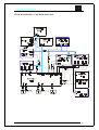
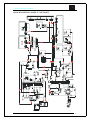
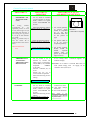
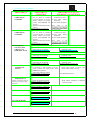
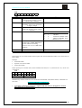
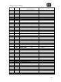
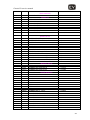
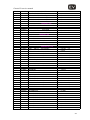
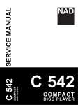
Chassis E9-service manual
V/2000
436551
CHASSIS E9
SERVICE MANUAL
•
•
Page
TECHNICAL SPECIFICATIONS TV SETS WITS CHASSIS E9…………….…………2
MODULES ARRANGEMENT ON CHASSIS……..……..……..……..……..…………….4
•
GENERAL INSTRUCTIONS……..……..……..…………...……..……..…5
X-RAY RADIATION……..……..……..……..……..……..……..……..…………………………5
SAFETY……..……..……..……..……..……..……..…………….……..……..……..……..……..5
MEASUREMENT CONDITIONS……..……..……..……..……..……..……..……..………….....6
• BLOCK DIAGRAM AND OPTIONS TABLES……..……..……..……..……..…………..7
• BLOCK DIAGRAM – CONTROL SIGNALS……..……..……….…..……..……..8
• BLOCK DIAGRAM - SUPPLY VOLTAGES……..……..……..……..……..……………..9
• SERVICE ADJUSTMENTS OF THE COLOUR TV WITH E9 CHASSIS………….....10
• ELECTRICAL DIAGRAM OF MAIN CHASSIS E9……..……..……..……..…………..23
• ELECTRICAL DIAGRAM OF MODULES FOR CHASSIS E9……..……..……….…..24
• OSCILLOGRAMS……..……..……..……..……..……..……..……..……..……..………..25
• MAIN CHASSIS - COMPONENT SIDE……..……..……..……..………..……..……..…26
• ELECTRICAL DIAGRAMS OF SEPARATE MODULES FOR CHASSIS E9……....27
• COMPONENT LOCATIONS ON SEPARATE MODULES OF CHASSIS E9 –
COMPONENT SIDE ……..……..……..……..……..……..……..……..……..……..……29
• LIST OF RECOMMENDED SPARE PARTS FOR CHASSIS AND MODULES …….34
1
Chassis E9-service manual
E9 CHASSIS - TECHNICAL SPECIFICATION – Rev.11
TVTEXT Version 1p
(SDA5252-2)
1. SCREEN
SIZE:
90° or 110°,
14”,20”,21”, 25”, 28”, 33”
(4:3).
2. AVAILABLE • PAL BG,
STANDARDS: • PAL I,H (opt.),
• PAL/SECAM BG (opt.),
• PAL/SECAM BG / DK
(opt.),
• NTSC through SCART
(opt.),
• SECAM L/L' (opt.).
HYPERBAND:
VHF 2-12,
3. TUNER:
UHF 21-69, S1-S41
Frequency synt. (125KHz
4. FEATURES:
search steps),
MENU oriented OSD (On
Screen Disp.)
100 programs,
Full function remote control,
Automatic switch off at the
end of the progr.
Off timer 0 - 120 min.,
Organise Program
Information System (OPIS)
with the following functions:
• Autostore
• Insert
• Delete
• Rename,
Hotel mode (opt.).
5. SOUND:
MONO/STEREO/DUAL
sound decoder,
Digital Stereo Sound
Processor,
Muting,
1 or 2 loudspeakers
(STEREO),
Audio music power output:
1x15W (MONO),
2x15W (STEREO),
STEREO through SCART
(opt.),
German STEREO + NICAM
(opt.),
TVTEXT Version 7p (SDA
5255-2)
TVTEXT Version Dolby 7p
(OTP)
90° or 110°,
21”, 25”, 28”, 33” (4:3),
28”, 32” (16:9).
• PAL BG,
• PAL I,H (opt.),
• PAL/SECAM BG (opt.),
• PAL/SECAM BG / DK (opt.),
• NTSC through SCART (opt.),
• SECAM L/L' (opt.).
90° or 110°,
21”, 25”, 28”, 33” (4:3),
28”, 32” (16:9).
• PAL BG,
• PAL I,H (opt.),
• PAL/SECAM BG (opt.),
• PAL/SECAM BG / DK (opt.),
• NTSC through SCART (opt.),
• SECAM L/L' (opt.).
HYPERBAND:
VHF 2-12,
UHF 21-69, S1-S41
Frequency synt. (125KHz search
steps),
MENU oriented OSD (On Screen
Disp.) Multilanguage MENU OSD,
100 programs,
Full function remote control,
Automatic switch off at the end of
the progr.
Off timer 0 - 120 min.,
Organise Program Information
System (OPIS) with the following
functions:
• Autostore with simple ATS:
Autostore,
Name, Order,
• Insert
• Delete
• Rename,
Copy funct. SCART2 to SCART1
(opt.),
Hotel mode (opt).
HYPERBAND:
VHF 2-12,
UHF 21-69, S1-S41
Frequency synt. (125KHz search
steps),
MENU oriented OSD (On Screen
Disp.)
Multilanguage MENU OSD,
100 programs,
Full function remote control,
Automatic switch off at the end of
the program
Off timer 0 - 120 min.,
Organise Program Information
System (OPIS) with the following
functions:
• Autostore with simple ATS:
Autostore, Name, Order,
• Insert
• Delete
• Rename,
Copy function SCART2 to SCART1
(opt.),
Hotel mode (opt.).
Dolby Surround Pro-Logic sound ,
MONO/STEREO/DUAL sound
decoder,
Digital Stereo Sound Processor,
Muting,
2 loudspeakers,
Additional 2 tweeter speakers
(opt.),
Built in additional Subwoofer
loudspeaker (Cabinet opt.),
Audio music power: 60W
(15W Left, 15W Right 15W Centre,
15W Surround)
German STEREO + NICAM (opt.),
Automatic volume levelling (opt),
Separate volume adj. on
Headphones.
MONO/STEREO/DUAL sound
decoder,
Digital Stereo Sound Processor,
Muting,
1 or 2 loudspeakers,
Audio music power:
1x15W (MONO),
2x15W (STEREO),
Additional 2 tweeter loudspeakers
(opt.),
Built in additional Subwoofer
loudspeaker with 30W music
power (Cabinet opt.),
STEREO through SCART (opt.),
German STEREO + NICAM
(opt.),
Automatic volume levelling
(opt.),
2
Chassis E9-service manual
Separate volume adj. on Headph.s
(opt.).
TVTEXT Version 1p
(SDA5252-2)
1 - page TTX with P26,
Westeuropean and
easteuropean language
support.
SCART I AV connector
7.
CONNECTIONS: (21 - pin)
video,
RGB,
SVHS,
HeadPhones Socket (opt.),
Antenna connection 75
ohms unbalanced.
6. TELETEXT:
8. ADDITIONAL
OPTIONS
1TPIP - 1 tuner picture in
picture (opt.),
9.VIDEO:
Black and Blue stretch,
Blue back when no video,
Automatic Colour limiting,
CTI (opt.),
ZOOM.
10.
≈65W for 90°
CONSUMPTION: ≈95W for 110°
POWER REQUIREMENTS:
Voltage/frequency:
230V/50Hz
rating (180V 250V)
24.12.1999
TVTEXT Version 7p (SDA
5255-2)
TVTEXT Version Dolby 7p
(OTP)
7 - page TTX with the TOP (opt.),
FLOF and P26,
Westeuropean and easteuropean
language support.
SCART I AV connector (21 - pin)
video, RGB and SVHS,
HeadPhones Socket (opt.),
SCART II (opt.),
MINI DIN SVHS connector with
chinch AV inputs (opt.), front or
backside AV - cabinet dependent,
External speakers connectors
(opt.),
Antenna connection 75 ohms
unbalanced,
1TPIP - 1 tuner picture in picture
(opt.),
2TPIP - 2 tuner picture in picture
(opt.) with the sound on the
headphones from 2nd tuner source.
Black and Blue stretch,
Blue back when no video,
Automatic Colour limiting,
Colour Temperature adjustment,
CTI (opt.),
ZOOM (4:3),
Linear picture zoom (16:9).
≈65W for 90°
≈95W for 110°
POWER REQUIREMENTS:
Voltage/frequency: 230V/50Hz
rating (180V - 250V)
7 - page TTX with the TOP (opt.),
FLOF and P26,
Westeuropean and easteuropean
language support.
SCART I AV connector (21 - pin)
video, RGB and SVHS,
HeadPhones Socket (opt.),
SCART II (opt.),
External speakers connectors (Front
L and R, Rear L and R
MINI DIN SVHS connector with AV
chinch inputs (opt.), front or
backside AV - cabinet dependent,
Antenna connection 75 ohms
unbalanced.
1TPIP - 1 tuner picture in picture
(opt.),
2TPIP - 2 tuner picture in picture
(opt.) with the sound on the
headphones from 2nd tuner source.
Black and Blue stretch,
Blue back when no video,
Automatic Colour limiting,
Colour Temperature adjustment,
CTI (opt.),
ZOOM (4:3),
Linear picture zoom (16:9).
≈65W for 90°
≈95W for 110°
POWER REQUIREMENTS:
Voltage/frequency: 230V/50Hz
Rating (180V - 250V)
3
MODULES ARRANGEMENT ON CHASSIS
12.12.1999
4
Chassis E9-service manual
GENERAL INSTRUCTIONS
X-RAY RADIATION
Picture tube is potential source of X-radiation of colour TV. Use exclusively original types of
replacement picture tubes, specified in technical documentation. Accelerating high voltage must not
exceed 30 kV. Supply voltage "B+" for horizontal output stage must be set according to the
specifications given in service manual.
SAFETY INSTRUCTIONS
Service interventions on colour TV can be performed by authorised and qualified personnel only,
considering the following instructions:
• During service interventions connect the TV set to mains voltage through separating (isolating)
transformer.
• During servicing procedures (replacement of individual components) disconnect the cord from mains
connector.
• After disconnection and before servicing wait about 30 sec. so that charged electrolytes and picture
tube are discharged.
• Provide for additional discharge of picture tube when replacing it and use protective means to
prevent injuries due to eventually broken glass.
• When changing modules or complete chassis, fix it with adequate elements (screws, latches, ...).
• Wires inside the TV set should not come in contact with sharp or hot areas.
• Integrated circuits and other semiconductors on chassis are sensitive to overvoltages and high
temperatures.
During service interventions they should be protected against too long heating with soldering iron (5
sec.), electrostatic discharges, short circuits between connectors etc. Therefore the following general
instructions should be followed:
• Use low impedance disconnecting transformer for connection of chassis to mains voltage.
• Use low voltage soldering irons with protective earthing.
• Chassis earthing should be equal to earthing of measuring and calibrating equipment and tools.
• When connecting instruments, first connect negative connector (mass, earth) and afterwards signal
connector.
• Voltages to be checked should be measured with suitable instruments. Do not use "short-circuit
methods" with pincets or screwdriver.
• Conductors under high voltage should not be placed near semiconductors on chassis.
• Installed IC’s, transistors and MOSFET’s are made in various semiconductor technologies (CMOS,
MOS, BIMOS or bipolar technology) and are more or less sensitive to exterior effects during
handling. All these elements should be handled in accordance with the requirements for
electrostatic protection. If these requirements are fulfilled, you prevent formation of undesired
electrostatic discharges which can destruct semiconductors or can activate destructive mechanisms,
which destroy circuit during operation.
Accumulated electrostatic charge is discharged through individual connectors of IC or transistor during
electrostatic discharges and current runs through semiconductor structure. Considering that thicknesses
of semiconductor substrate, used for IC, are very small, this current can cause damages to IC or destroy
it. For the protection of circuits the currents originating from discharges should be discharged under
control. This is obtained in the following ways:
• Staff handling the ICs should have earthed hands by means of a suitable wire and resistor.
• Working table should as well be earthed. Working surface should be made of conducting material
(conducting rubber), soldering irons and all required equipment should be earthed.
• Carrying and storing is permissible only in original packaging (antistatic tubes, conducting
sponges).
• If IC is mounted on a base, it should not be replaced under voltage.
5
Chassis E9-service manual
MEASUREMENT CONDITIONS
• HF input signal in antenna: 1mV, with ″Philips″ test signal
• Input video signal on SCART connector: 1 Vpp
• Input audio signal on SCART connector: 500 mVeff
• Brightness, contrast and colour of picture, volume of sound set to normal (near middle of scale)
• Measure DC voltages with digital voltmeter with 1% precision
• Measuring instrument (voltmeter or oscilloscope) connect to tuner ground during measuring on
secondary side of mains (SMPS) transformer and on primary side during measuring on primary side
SMPS supply circuit.
6
BLOCK DIAGRAM AND OPTIONS TABLES
HARDWARE OPTIONS FOR
PROCESSORS (IC901)
SOUN PROCESSOR TYPES
TYPE
TDA 3400
SOUN STANDARD
STEREO+AM(L/L')
(till 2xscart)
TDA 3410D STREO+NICAM
nd
(more like 2xscart, 2
tuner)
TDA 3401 G STEREO+VIRT.
DOLBY
TDA 3401
STEREO (till 2x
scart)
TDA 3415
STEREO+NICAM (till
2xscart)
SCART 2
J910
J911
9
ENABLE
9
DISABLE
SECAM L
J902
ENABLE
9
DISABLE
D/K
J906
ENABLE
9
DISABLE
COPY OPTION (what is
on AV1, or from AV2 ->
J905
to AV1)
ENABLE
9
DISABLE
PCB
ST/E6-E9
ST/E6-E9
ST/E6-E9
ST/E9
ST/E9
SL1-E9
TUNER SELECTION*:
TUNER SELECTION
J901
J912
SIEL
9
ALPS
9
TEMIC and SELTEKA
9
9
TEMIC and SELTEKA
*except SDA5255 A052 - only SIEL
7p
only
DOLBY PROLOGIC
APD-E9
K1303
K1301
Lext
K73
SUR1
TDA2616A
KD-E6
SUB
SIGNAL & DEFL.
PROCESSOR SEL.
TDA8840
TDA8842
TDA8843
TDA8844
7p
only
90°
90°
110°
110°
AP-E9
PAL
PAL/SECAM
PAL
PAL/SECAM
DZ1
K74B
K1301
TUNER2
FL2477/84
TDA884X
MSP34XX
TDA2545A
DPL3519A
SIGNAL AND
DEFL.
PROCESSOR
K-1201B K-1202B K1203B
K508A
K510A
AUDIO OUT
AUDIO-R
K92C
K508B
K404A
L,R
C,Y
L
K001C
K500A, K501A, K502A, K503A, K504A
RGB
K102A
SVHS-E9
K404B
TDA8540
SFTL-E9
K104B
K104C
K401B
K402B
K401A
K402A
EU-E9
K901B
IC1
PR- PR+
+
SDA5250
M
K901B
L,R
IC902
K751
K902A
K800B,K801B,K802B,K803B,K804B,K805B
K800A,K801A,K802A,K803A,K804A,K805A
PR- PR+
+
TP-E9
PR- PR+
M
K901B
+
M
POWER SUPPLY
TDA4605-2
BUZ90A
150V
33V
24V
12V
8V
5VA
5V
15VT
LZZ-E9
K752
SAA9288
TDA8310
CVBS_SC2
K901B K901A
MODULES VK IN PICTURE TUBES
K806B
PIP-E9
IC903
SDA525X
CVBS_SC1
OC-E9
a
a
R-626
K106A
b
K105A
SCART 2
K704B
K703A
K704A
H.DRIVE
EW DRIVE
H. FLY
EHT COMP
BU508A (110)
BU508D (90)
SCART 1
230V AC
PROCESSOR & EEPROM SELECTION
Text
IC901
pages
SDA5252-2 B001 EV E9 1P 17 99
SDA5255 B002 EV E9 1P 19 99
SDA5255 A052
SDA5255-2 B001 EV E9 7P 27 99
SDA5255 B003 EV E9 7P 29 99
Piggy back with SDA 5250
SDA545x OTP
K703B
HOR. OUT
b
1p
1p
7p
7p
7p
7p
1p/7p
R
G
B
TDA8351 (110)
TDA8356 (90)
IC901
TP-CG
K101B
VERT. OUT
VIDEO
SWITCH
TEA2014
K1
K2
K3
K4
CVBS int
CVBS_ext
VK-E9: 4:3
VK-E9T: 16:9
VK-E9M: minineck
TDA6107
TDA6108
V+
VGUARD
K403B
K104B
TDA7057A
S1-IN
K92B
Lext
R
K104A
K500B, K501B, K502B, K503B, K504B
K-1201A K-1202A K1203A
AUDIO-L
Rext
K72
TDA2616
NE5532
STEREO: ST-E9,ST-E6/9
DOLBY: STD-E9
K506A
K507
MONO: /
SAW
filter
TDA9800
K-1201B K-1202B K1203B
K92A
SRext
SLext
1p/7p
TUNER1
FL2477/84
(na poz. KD-E6)
VIDEO
Cext
K71
SAT-EU
K91
K51
K74
K104B
K104C
E9
S-VHS
Rext
SD1
IC902
IC903 Optional no.
Picture tube
Manufacturer
VK-E9 (4.3) basic for 90° in 110° pict. tubes
A48EAX13X01
Thomson
A48EEV13X01
Thomson
A51EBV13X01
Thomson
A51EAL30X01
Vista
A51EAL155X01
Philips
A51EJJ01X01
Ekranas
VK-E9T (16:9) for 16:9 pict. tubes
W66EHK50X06
Panasonic
W66EHK51X26
Panasonic
W76EGV23X115
Videocolor
W76EGX23X115
Videocolor
VK-E9T1 (16:9) for 16:9 pict. tubes
W76ESF031X14
Philips
VK-E9M (4:3) for minineck pict. tubes
A48JAN43X02
BPL
A51JAR70X05
BPL
10.12.1999
languaes
24C08
24C08
/
/
24C16
or
24C08AT
/
24C32
/
/
up to 1
up to 4
7
Chassis E9-service manual
BLOCK DIAGRAM – CONTROL SIGNALS
8
Chassis E9-service manual
BLOCK DIAGRAM - SUPPLY VOLTAGES
9
Chassis E9-service manual
SERVICE ADJUSTMENTS OF THE COLOUR TV WITH E9 CHASSIS
All necessary adjustments and settings are performed during manufacture of TV set and assure its
correct operation when connected to the mains voltage and antenna or external video or audio signal.
When TV set requires service intervention all settings should be checked and corrected, if necessary.
DEMAGNETISING OF PICTURE TUBE
Correctness of picture tube demagnetising is usually automatically checked. Magnetisation of picture
tube is presented as one or more colour "clouds", consequently colour reproduction of the picture is
not correct.
Each time the TV set is switched on with mains switch, demagnetising system is activated. For correct
demagnetising procedure disconnect the TV set with mains switch and leave it disconnected for about
15 minutes. Afterwards when you switch on the TV, demagnetising procedure is performed. In case
distortion of colour reproduction still persists, special demagnetising coil should be used.
ADJUSTMENT
1. SUPPLY VOLTAGE
FOR HORIZONTAL
OUTPT STAGE
»B+«
ADJUSTMENT
CONDITION
•
•
•
Connect the TV set to
supply
voltage
175…250VAC.
Switch it on and set it by
means
of
remote
controller to AV mode of
operation.
Connect DC voltmeter to
D-602 cathode.
ADJUSTMENT ACTIVITY
AND RESULT OF SETTINGS
With P-601 potentiometer set supply voltage for
horizontal output stage to:
• 90° CTV:
118V ±0,2V
• 110° CTV:
155V ±0,2V
• 110°/16:9 CTV: 155V ±0,2V
SWITCHING TO SERVICE MODE
All other service settings of TV set are made in so called service mode of TV set operation. To enter this mode of operation press
the keys in the following sequence: "TV", "I", and "STOP" in the period of 5 seconds from switching on the TV set to normal mode
of operation. When the TV set is switched over to service mode the following status line with service parameter and parameter value
appears on the screen:
SERVICE PARAM: XX VALUE: xx
The parameter to be set is selected with keys
(P+/P-), and selected parameter is set with keys
(volume+ /volume-). Each
) the value of preselected parameter is stored. Therefore when the last setting is
time you press the key for parameter selection (
performed you must press one of the two keys once again. Values of individual parameters are expressed in hexadecimal form due
to limited capacity of the memory. Values of individual parameters are variable from 0 to 3F, with the exception of parameters 11,
12 and 13 where values are changed from 0 to 7F and O1, O2, O3, O4, which have value range between 0 and FF.
When setting is finished it should obligatory be concluded with "STOP" key. After a few seconds the status line disappears and
service adjustment is accomplished.
NOTE: In case service adjustment is not ended in above specified mode (e.g. power supply breakdown), the
adjustment should be repeated.
2. VERTICAL
• To antenna connector of • With
remote
PICTURE
TV set, which is switched
controller set vertical
POSITION
on and operates in service
position
of
the
mode, connect VF signal
picture: beginning of
source with PHILIPS test
dark part of the 4:3
picture.
picture should be
exactly in the centre
• Select the following service
of the screen (two
setting on the screen:
bright points on left
SERVICE PARAM: VH VALUE: xx
and right side of the
16:9
screen).
10
Chassis E9-service manual
ADJUSTMENT
3.
VERTICAL
AMPLITUDE
ON TOP PART
OF SCREEN
ADJUSTMENT
CONDITION
• To antenna connector of TV
set, which is switched on
and operates in service
mode, connect VF signal
source with PHILIPS test
picture.
• Select the following service
setting on the screen:
ADJUSTMENT ACTIVITY
AND RESULT OF SETTINGS
•
With
remote
controller set vertical
amplitude of picture
on top, visible part of
the
screen.
The
beginning of test
picture should be at
the beginning of top
part of the screen.
SERVICE PARAM: VA VALUE: xx
4. VERTICAL
AMPLITUDE ON
BOTTOM PART OF
SCREEN
•
•
To antenna connector of
TV set, which is switched
on and operates in service
mode, connect VF signal
source with PHILIPS test
picture.
Select the following service
setting on the screen:
SERVICE PARAM: VS VALUE: xx
5. CORRECTION OF
"S" VERTICAL
PICTURE
DISTORTION
• To antenna connector of TV
set, which is switched on
and operates in service
mode, connect VF signal
source with PHILIPS test
picture.
• Select the following service
setting on the screen:
SERVICE PARAM: SC VALUE: xx
6. HORIZONTAL
PICTURE
POSITION
•
•
To antenna connector of
TV set, which is switched
on and operates in service
mode, connect VF signal
source with PHILIPS test
picture.
Select the following setting
on the screen:
4:3
16:9
•
With
remote
controller set vertical
amplitude of picture
on bottom part of the
screen. The lower
part of test picture
should be at the edge
of bottom part of the
screen. During this
setting the picture on
top part of the screen
should not change.
• With
remote
controller correct the
picture. The distances
between the two
horizontal lines of
test picture in the
centre of the screen
should be equal to the
distances on top and
bottom part of the
screen. If after this
setting
vertical
amplitude of picture
changes, see pos. 5
and 6.
• With
remote
controller set test
picture to the centre
of the screen (if
necessary first widen
the picture, see pos.
7).
4:3
16:9
4:3
16:9
4:3
SERVICE PARAM: HS VALUE: xx
16:9
11
Chassis E9-service manual
ADJUSTMENT
7.
HORIZONTAL
AMPLITUDE
OF PICTURE
ADJUST ONLY AT:
- 110°-4:3
16:9
ADJUSTMENT
CONDITION
• To antenna connector of TV
set, which is switched on
and operates in service
mode, connect VF signal
source with PHILIPS test
picture.
• Select the following service
setting on the screen:
ADJUSTMENT ACTIVITY
AND RESULT OF SETTINGS
•
With
remote
controller set picture
width. Edges of test
picture should be just
hidden behind the
edges of the screen.
SERVICE PARAM: EW VALUE: xx
7/A. HORIZONTAL
AMPLITUDE
OF PICTURE
FOR 90°°
ADJUST ONLY AT:
- 90°
8. CORRECTION OF
PICTURE
HORIZONTAL
PINCUSHION
DISTORTION
ADJUST ONLY AT:
- 110°-4:3
16:9
• To antenna connector of TV
set, which is switched on
and operates in service
mode, connect VF signal
source with PHILIPS test
picture.
• For CTV is not necessary to
be in service mode.
• To antenna connector of
TV set, which is switched
on and operates in service
mode, connect VF signal
source with PHILIPS test
picture.
• Select the following service
setting on the screen:
• With coil L702 set
picture width. Edges
of test picture should
be just hidden behind
the edges of the
screen.
•
SERVICE PARAM: PW VALUE: xx
With
remote
controller correct the
picture. On left and
right side of test
picture straight lines
should
appear
(especially in the
centre
of
the
picture).
4:3
16:9
9. CORRECTION OF
PICTURE
HORIZONTAL
PINCUSHION
DISTORTION IN
CORNERS OF THE
SCREEN
ADJUST ONLY AT:
- 110°-4:3
16:9
• To antenna connector of TV
set, which is switched on
and operates in service
mode, connect VF signal
source with PHILIPS test
picture.
• Select the following service
setting on the screen:
10. CORRECTION OF
PICTURE
TRAPEZIUM
DISTORTION
ADJUST ONLY AT:
- 110° -4:3
16:9
•
•
With
remote
controller correct the
picture. On left and
right part of test
picture straight lines
should appear also in
corners of the screen.
SERVICE PARAM: CP VALUE: xx
•
To antenna connector of
TV set, which is switched
on and operates in service
mode, connect VF signal
source with PHILIPS test
picture.
Select the following service
setting on the screen:
4:3
16:9
• With
remote
controller correct the
picture. On left and
right part of test
picture
perfectly
straight and vertical
lines should appear.
4:3
SERVICE PARAM: TC VALUE: xx
16:9
REMARK:
If after correcting pincushion and trapezoidal distortion, changes the horizontal amplitude of picture, is necessary to
correct also horizontal amplitude of picture according to explanation in point 7.
12
Chassis E9-service manual
ADJUSTMENT
ADJUSTMENT
CONDITION
11. HORIZONTAL
AMPLITUDE FOR
16:9 PICTURE
TUBES
•
ADJUST ONLY AT:
16:9
•
To antenna connector of
TV set, which is switched
on and operates in service
mode, connect VF signal
source with PHILIPS test
picture.
Select the following service
setting on the screen:
ADJUSTMENT ACTIVITY
AND RESULT OF SETTINGS
•
With
remote
controller set picture
width. Correct 4:3
picture
geometry
should be obtained.
SERVICE PARAM: EW VALUE: xx
12
ZOOM OF
PICTURE
GEOMETRY (4:3)
ADJUST ONLY AT:
4:3
•
•
To antenna connector of
TV set, which is switched
on and operates in service
mode, connect VF signal
source with PHILIPS test
picture.
Select the following setting:
SERVICE PARAM: X1 VALUE: xx
• Select the following setting:
SERVICE PARAM: E1 VALUE: xx
• Select the following setting:
SERVICE PARAM: S1 VALUE: xx
12/A.
»MOVIE
EXPAND« GEOMETRY
OF ZOOM PICTURE
(16:9)
REMARK:
The
setting
enables
reproduction
of 4:3
picture through entire 16:9
screen (with cut off edges
on top and bottom side)
and "letterbox" picture
without black edges. This
format
is
also
automatically selected if
WSS code is present
(PALplus).
ADJUST ONLY AT:
16:9
•
•
To antenna connector of
TV set, which is switched
on and operates in service
mode, connect VF signal
source with 16:9 "letterbox"
test picture.
Select the following setting:
SERVICE PARAM: X1 VALUE: xx
• Select the following setting:
SERVICE PARAM: E1 VALUE: xx
• Select the following setting:
SERVICE PARAM: S1 VALUE: xx
• Set vertical geometry
of
picture.
The
picture
should
expand up to first
horizontal white line
on test picture.
• Increase horizontal
amplitude of picture.
The picture should
be expanded up to
the first vertical
white line on test
picture.
• Set the picture to the
centre of the screen
(if necessary).
• Set vertical geometry
of the picture. The
picture should be
expanded up to the
edges of the test on
top and bottom side.
• Set
horizontal
amplitude of picture.
The picture should be
expanded up to the
edge of test.
• Set position of the
picture to the centre
of the screen.
hatched line: expand
(ZOOM) picture
4:3 picture
»letterbox picture«
13
Chassis E9-service manual
ADJUSTMENT
13.
PIP PICTURE
POSITION ON
LEFT SIDE
Adjust only at CTV with
PIP module.
ADJUSTMENT
CONDITION
•
To antenna connector of TV
set, which is switched on
and operates in service
mode, connect VF signal
source with PHILIPS test
picture.
•
Select the following setting:
ADJUSTMENT ACTIVITY
AND RESULT OF SETTINGS
•
With
remote
controller set desired
PIP position of
picture.
•
With
remote
controller set desired
PIP position of
picture.
•
With
remote
controller set desired
position
of
PIP
picture when picture
is expanded.
•
With
remote
controller set desired
position
of
PIP
picture when picture
is expanded..
SERVICE PARAM: P1 VALUE: xx
14.
PIP PICTURE
POSITION ON
RIGHT SIDE
Adjust only at CTV with
PIP module.
•
To antenna connector of
TV set, which is switched
on and operates in service
mode, connect VF signal
source with PHILIPS test
picture.
• Select the following setting:
SERVICE PARAM: P2 VALUE: xx
15.
PIP PICTURE
POSITION ON
LEFT SIDE
(ZOOM)
Adjust only at CTV with
PIP module.
•
To antenna connector of TV
set, which is switched on
and operates in service
mode, connect VF signal
source with PHILIPS test
picture.
• Select the following setting:
SERVICE PARAM: P3 VALUE: xx
16.
PIP PICTURE
POSITION ON
RIGHT SIDE
(ZOOM)
Adjust only at CTV with
PIP module.
• To antenna connector of TV
set, which is switched on
and operates in service
mode, connect VF signal
source with PHILIPS test
picture.
• Select the following setting:
SERVICE PARAM: P4 VALUE: xx
14
Chassis E9-service manual
ADJUSTMENT
17. »ZOOM1«
GEOMETRY OF
ZOOM PICTURE
(16:9)
The
setting
enables
reproduction
of
4:3
expanded picture on 16:9
screen (black edges on left
and right side decrease, a
part of picture at top and
bottom is cut off).
Setting is possible only
when colour TV is
configured
for
16:9
picture tubes).
ADJUST ONLY AT:
16:9
ADJUSTMENT
CONDITION
•
To antenna connector of
TV set, which is switched
on and operates in service
mode, connect VF signal
source with PHILIPS test
picture.
•
Select the following setting:
The setting enables correct
reproduction
of
»letterbox« picture on 4:3
screen (black edges on top
and bottom).
•
SERVICE PARAM: X2 VALUE: xx
Set vertical geometry
of picture which
should be expanded
up to the first
horizontal white line
on test picture of
page.
• Select the following setting:
•
Set picture width so
as to get correct 4:3
picture geometry.
• Select the following setting:
•
Set picture position
in the centre of the
screen.
•
Set vertical geometry
of picture as long as
circle get correct
round
form
in
letterbox test picture.
SERVICE PARAM: E2 VALUE: xx
SERVICE PARAM: S2 VALUE: xx
17/A. »ZOOM1«
GEOMETRY OF
ZOOM PICTURE
AT 4:3
ADJUSTMENT ACTIVITY
AND RESULT OF SETTINGS
•
To antenna connector of
TV set, which is switched
on and operates in service
mode, connect VF signal
source with letterbox 16:9
test picture.
•
Select the following setting:
SERVICE PARAM: X2 VALUE: xx
• Select the following setting:
SERVICE PARAM: E2 VALUE: xx
• Select the following setting:
SERVICE PARAM: S2 VALUE: xx
.
•
•
Set picture width as
long as the edges of
test picture should
be
just
hidden
behind the edges of
the screen.
»ZOOM1«
»Letterbox« on 4:3
picture tube
Set picture position
in the centre of the
screen.
15
Chassis E9-service manual
ADJUSTMENT
18.
»ZOOM2«
GEOMETRY OF
ZOOM PICTURE
(16:9)
The
setting
enables
reproduction of
4:3
expanded picture on 16:9
screen (black edges on left
and right side decrease, a
part of top part of picture
is cut off so that subtitles
are visible.
Setting is possible only in
case the colour TV is
configured for 16:9 picture
tubes.
ADJUSTMENT
CONDITION
•
To antenna connector of
TV set, which is switched
on and operates in service
mode, connect VF signal
source with PHILIPS test
picture.
•
Select the following setting:
ADJUSTMENT ACTIVITY
AND RESULT OF SETTINGS
•
SERVICE PARAM: X3 VALUE: xx
• Select the following setting:
•
ADJUST ONLY AT:
16:9
• Select the following setting:
•
19. OPERATING
THRESHOLD OF
AUTOMATIC
AMPLIFICATION
REGULATION
•
SERVICE PARAM: E3 VALUE: xx
SERVICE PARAM: S3 VALUE: xx
•
•
•
To antenna connector of
TV set, which is set to
channel 12, connect VF
signal source of frequency
224,25 MHz (C12) with RF
amplitude
60dB/uV
(1mV/75E).
Connect voltmeter, dc, on
C107.
Switch the TV set to
service mode of operation.
Select the following service
setting:
Set vertical geometry
of picture which
should be expanded
up to the first
horizontal white line
on test picture of
page.
»ZOOM2«
(»Titled Movie Expand)
Set picture width so
as to get correct
4:3picture geometry.
Set picture position.
Picture should be
shifted
upwards
(bottom edge of
picture up to bottom
edge of screen).
• With remote controller keep changing the value
of AC setting until 7.5V±0,5V appears on
voltmeter display.
REMARK: If in chassis is inserted WW form of
tuner (small casing), with 5V supply, set on
voltmeter value 2,8V±0,1V.
SERVICE PARAM: AC VALUE: xx
20. RED COMPONENT
OF WHITE
•
•
To antenna connector of
TV set, which is switched
on and operates in service
mode, connect VF signal
source with PHILIPS test
picture.
Select the following service
setting:
SERVICE PARAM: R VALUE: xx
• With
remote
controller set value:
1F: Pict. Tube Philips,
Panasonic.
1F: Pict. Tube Thomson.
This
value
is
for
orientation and depends
of picture tube.
16
Chassis E9-service manual
ADJUSTMENT
21. GREEN
COMPONENT
OF WHITE
ADJUSTMENT
CONDITION
•
•
To antenna connector of
TV set, which is switched
on and operates in service
mode, connect VF signal
source with PHILIPS test
picture.
Select the following service
setting:
SERVICE PARAM: G VALUE: xx
22. BLUE
COMPONENT
OF WHITE
•
•
To antenna connector of
TV set, which is switched
on and operates in service
mode, connect VF signal
source with PHILIPS test
picture.
Select the following service
setting:
SERVICE PARAM: B VALUE: xx
23. REFERENCE
OSCILLATING
CIRCUIT OF
DEMODULATOR
•
With remote controller
following service setting:
ADJUSTMENT ACTIVITY
AND RESULT OF SETTINGS
• With
remote
controller set value:
24: Pict. Tube Philips,
Panasonic.
28: Pict. Tube Thomson.
This
value
is
for
orientation and depends
of picture tube.
• With
remote
controller set value:
24: Pict. Tube Philips,
Panasonic.
20: Pict. Tube Thomson.
This
value
is
for
orientation and depends
of picture tube.
PAL /SECAM BG/L
select the • With keys for set value changing set
parameter value.
SERVICE PARAM: I1 VALUE: xx
PAL /SECAM /L'
• With remote controller
following service setting:
SERVICE PARAM: I1 VALUE:40
select
the
SERVICE PARAM: I2 VALUE: 00
PAL /SECAM /DK
• With remote controller
following service setting:
SERVICE PARAM: I2 VALUE: 00
the
• With keys for set value changing set
parameter value.
To antenna connector of TV set, which
is switched on and operates in service
mode, connect VF signal source with
PHILIPS test picture.
Select the following setting:
• With remote controller set such delay
select
SERVICE PARAM: I3 VALUE: 40
24. TIME DELAY OF
LUMINANCE
SIGNAL
•
•
25. MAX. VOLUME
FOR HOTEL TV
Setting is possible only for
colour TV configured for
hotel TV.
26. OPTION BYTE 1
• Select the following setting:
•
SERVICE PARAM: HM VALUE: xx
With remote controller set desired
value of volume.
• Select the following setting:
•
See option bytes.
• Select the following setting:
•
See option bytes.
• Select the following setting:
•
See option bytes.
• Select the following setting:
•
See option bytes.
SERVICE PARAM: O3 VALUE: xx
29. OPTION BYTE 4
setting that signals of colour and
black - white picture overlap.
Recommended value: D
SERVICE PARAM: O2 VALUE: xx
28. OPTION BYTE 3
SERVICE PARAM: I3 VALUE: 40
SERVICE PARAM: YD VALUE:xx
SERVICE PARAM: O1 VALUE: xx
27. OPTION BYTE 2
• With keys for set value changing set
parameter value.
SERVICE PARAM: O4 VALUE: xx
17
Chassis E9-service manual
ADJUSTMENT
30. VOLTAGE FOR
PICTURE TUBE
BEAM FOCUSING
ADJUSTMENT
CONDITION
Switch the colour TV with
STOP key on remote
controller to normal mode
of operation.
Connect signal with Philips
test picture to antenna
connector.
•
With potentiometer for focusing voltage
adjustment on HV transformer set such value of
voltage, that gives sharp picture on entire surface
of the screen. Sharpness should be equal in
corners and in centre of the screen.
Required instruments:
• oscilloscope,
• oscilloscope probe 100:1;
• Cp=2,5pF
(oscilloscope
setting 0,5V/div; 5ms/div:
ext. actuation with vertical
time basis of TV set).
Procedure:
• To
antenna
connector
connect signal with Philips
test picture.
• With oscilloscope probe
search on video output
stage for the cathode of
picture tube on which video
signal has highest voltage
level of black (oscilloscope
setting: 0,5V/div; 20 us/div:
int. triggering). The probe
should remain connected to
this cathode.
• Change the setting of
oscilloscope to 5ms/div and
ext. Triggering with vertical
time basis of TV set and on
oscillogram search for
measuring "ABS" impulse
(automatic black point
stabilisation).
•
With potentiometer
for second grid
voltage adjustment
on HV transformer
set such value of
»ABS« pulse to
voltage 130±2 V.
•
•
•
•
31.
32.
VOLTAGE OF
SECOND GRID OF
UG2 PICTURE
TUBE
REFERENCE
OSCILLATING
CIRCUIT OF
SOUND
DEMODULATOR
Applies to stereo version of
TV set.
ADJUSTMENT ACTIVITY
AND RESULT OF SETTINGS
To antenna connector of TV
set, which is switched on
and operates in service
mode, connect VF signal
source with PHILIPS test
picture and with 1kHz
modulated sound carrier.
ABS pulse
130V
0V
Connect oscilloscope
probe
IC525
to
connector 12.
•
Rotating the core of
L521 coil set min.
content of video
signal.
18
Chassis E9-service manual
OPTION BYTES
Option bytes enable programme configuration of colour TV set. Changing individual bites of a
byte modifies the characteristics of TV set.
O1:
7
6
5
4
BIT
0
1
2
3
2
1
0
1
NTSC ENABLE
BLUE BACK ENABLE
DYNAMIC SCIN CORRECTION
ANGLE 123º
DYNAMIC SCIN CONTROL
ENABLE
BLUE STRATCH ENABLE
BLACK STRATCH ENABLE
HOTEL MODE ENABLE
COMB FILTER ENABLE
3
4
5
6
7
0
NTSC DISABLE
BLUE BACK DISABLE
DYNAMIC SCIN CORRECTION
ANGLE 118º
DYNAMIC SCIN CONTROL
DISABLE
BLUE STRATCH DISABLE
BLACK STRATCH DISABLE
HOTEL MODE DISABLE
COMB FILTER DISABLE
O2:
7
6
5
4
BIT
0
1
3
2
1
0
1
PAL I ENABLE
MULTISTANDARD ENABLE
(BG/DK- if option jumper not
insert; I- if bit PAL I enable)
HBL bit ENABLE
OPTION LANGUAGE ENABLE
16:9
TOP ENABLE
USER SET 38
HEADPHONE MENU DISABLE
2
3
4
5
6
7
0
PAL I DISABLE
MULTISTANDARD DISABLE (if
PAL I enable - only PAL I; BG/DK if option jumper DK not insert)
HBL bit DISABLE
OPTION LANGUAGE DISABLE
4:3
TOP DISABLE
USER SET 06
HEADPHONE MENU ENABLE
O3:
7
6
BIT
0
1
2
3
4
5
6
7
5
4
3
2
1
0
1
0
CTI ENABLE
CTI DISABLE
WELCOME MESSAGE ENABLE
WELCOME MESSAGE DISABLE
MSP 3401 ENABLE
MSP3401 DISABLE
AUTOMATIC SWITCH ON (B SEC) 8 SEC. DELAYED SWITCH ON
AVL OPTION ENABLE
AVL DISABLE
HBL & TXT OFF (110 chassis)
HBL & TXT ON (ONLY pure TXT not in UPDATE or MIX)
- 90 chassis – always ON
ZOOM is DISABLE (only 4:3)
ZOOM is ENABLE
ITALIAN CHANNELS (C13-C20) ITALIAN CHANNELS DISABLE
ENABLE
19
Chassis E9-service manual
O4:
7
6
5
BIT
0
4
3
2
1
0
1
LOW STANDBY ENABLE (save
and read Zoom_settings at switch
off and anew switch on)
AUTO ON ENABLE (for
automatic switch on at connection
to supply voltage)
ZET CORRECTION ENABLE
(additional menu for setting rotation
of picture)
VIRTUAL OPTION
1
2
3&4
5
DK ALTERNATE SOUND
6.5Mhz and 5.74MHz (RED button
in menu ADJUST switching
between 6.25 in 5.74 at DK sound
standard)
0
LOW STANDBY DISABLE
AUTO ON DISABLE
ZET CORRECTION DISABLE
bit 4
0
0
1
1
bit 3
0
1
0
1
FUNCTION
SPACE effect
3D effect
VIRTUAL DOLBY effect
VIRTUAL DOLBY, but in
MENU text 3D
DK SOUND 6.5MHz and 6.25MHz
6
7
Option bytes are set so that besides selected option byte also hexadecimal number is set on the basis of
above tables.
Example:
• blue back-enable
• dynamic scin control enable
• blue stratch enable
Select option byte O1 and for items, which should be activated, set “1” (other bites are “0”). In our case
is as follows:
O1:
7
0
6
0
5
0
1
4
1
3
1
2
0
1
1
0
0
A
Shaded binary number should now be converted to hexadecimal value (darker frame). Afterwards set
this value.
SERVICE PARAM: O1 VALUE: 1A
•
CAUTION: Option bytes are Factory adjusted and must NOT be changed later, because
they change TV set characteristics.
20
Chassis E9-service manual
For conversion from binary to hexadecimal help us next table:
0
0
0
0
0
0
0
0
1
1
1
1
1
1
1
1
BIN
0
0
0
0
0
1
0
1
1
0
1
0
1
1
1
1
0
0
0
0
0
1
0
1
1
0
1
0
1
1
1
1
0
1
0
1
0
1
0
1
0
1
0
1
0
1
0
1
HEX
0
1
2
3
4
5
6
7
8
9
A
B
C
D
E
F
33. INFORMATION MENU ABOUT INTEGRIRATED CIRCUITS, CONNECTED TO I2CBUS
If you press i key (info) on remote control when the TV set is in service mode, you will get on the
screen information about the version of current software (e.g.: VER:E9F1.6) and devices connected on I2C
bus:
SERVICE
VER: E9F1.6
VIDEO PR. OK TDA8843
MSP 34XX OK
SDA9288
XX
TUNER2
XX
TDA 8540
TDA8425
Video processor:
MSP 34XX:
SDA 9288:
TUNER2:
TDA 8540:
TDA 8425:
WD:00
SP:FF
Bus controlled TV processor for video and audio signal
Digital stereo sound processor
PIP processor
Second tuner for PIP picture
SVHS video matrix switch
HI-FI Stereo audio processor for stereo through SCART connector
If device is installed and properly connected on I2C bus it will respond with “OK” beside the name of
device, otherwise there will be “XX” on this place.
21
ELECTRICAL DIAGRAM OF MAIN CHASSIS E9
23
ELECTRICAL DIAGRAM OF MODULES FOR CHASSIS E9
24
Chassis E9-service manual
OSCILLOGRAMS
25
MAIN CHASSIS – COMPONENT SIDE
26
Chassis E9-service manual
ELECTRICAL DIAGRAMS OF SEPARATE MODULES OF CHASSIS E9
27
Chassis E9-service manual
28
Chassis E9-service manual
COMPONENT LOCATIONS ON SEPARATE MODULES OF CHASSIS E9 –
COMPONENT SIDE
VK-E9T1
VK-E9
VK-E9T
VK-E9M
29
Chassis E9-service manual
PIP-E9
SOLDER SIDE
COMPONENT SIDE
30
Chassis E9-service manual
ST-E9
S1-IN
APD-E9
SVHS-E9
AP-E9
31
Chassis E9-service manual
SFTL-E9
OC-E9
TP-CG
TP-E9
LZZ-E9
32
Chassis E9-service manual
STD-E6 (module Dolby surround)
ST-E6 (module stereo)
33
Chassis E9-service manual
LIST OF RECOMMENDED SPARE PARTS FOR CHASSIS AND MODULES
INDEX
110
90
CODE
412499
414653
415949
338557
414794
415947
415032
412517
W, 90
414655
110, W28<< 413778
W-PH
415881
110-PH
429359
110-34«
433921
413782
W-32«
425838
110-34«
433920
90-EK
316792
110
338584
90-VC
412924
90-PH
413777
90-PH
415688
W-28«
425986
415936
W-32«
428781
110
415936
W-28«
425986
415937
429609
429610
429611
313551
313551
300874
51666
51666
51666
51666
51666
51666
51666
51666
51666
51666
51666
51666
51666
412464
VALUE
MAIN CHASSIS
220U M400V
C/EL
C/EL
100U M400V
C/EL
PR 5,0 2U2 M350V
C/EL
PR 5,0 10U T250V
C/EL
PR 5,0 47U M160V
C/EL TR 5,0
1U0 M250V
C/EL TR 5,0
2U2 M250V
C/K/KO/Z/2E4 *
2N2M250VAC
C/MPP PR *
U47 J 250V
C/MPP PR *
U33 J 250V
C/MPP PR *
U39 J 250V
MODULE CAP-E9 PH1
MODULE CAP-E9 34
C/MPP PR *
U68 M 250V
C/PP PR *
U015 J 1,6KV
MODULE CAP-E9 34
C/PP PR* 7800P J 1,6KV
C/PP PR*
U011 J 1,6KV
C/PP PR* 6800P J 1,6KV
C/PP PR* 8200P J 1,6KV
C/PP PR* 8500P J 1,6KV
C/PP PR*
U012 J 1,6KV
C/PP PR*
U033 K 630V
C/PP PR*
U015 J 1KV
C/PP PR*
U033 K 630V
C/PP PR*
U012 J 1,6KV
C/PP PR15,0 220P J 1,6KV
C/X2 PR*
U47 M 275VAC
C/X2 PR15,0 U10 M 275VAC
C/X2 PR22,5 U22 M 275VAC
D/SI/1N4001
TA
D/SI/1N4001
TA
D/SI/1N4003
TA
D/SI/1N4148
TA
D/SI/1N4148
TA
D/SI/1N4148
TA
D/SI/1N4148
TA
D/SI/1N4148
TA
D/SI/1N4148
TA
D/SI/1N4148
TA
D/SI/1N4148
TA
D/SI/1N4148
TA
D/SI/1N4148
TA
D/SI/1N4148
TA
D/SI/1N4148
TA
D/SI/1N4148
TA
D/SI/BAT85
TA
POSITION
C-9642
- // C-9709
C-9606
C-9605
C-9714
C-9202
C-9645
C-9707
- // - // - // - // C-9715
C-9711
- // - // - // - // - // - // - // C-9627
C-9713
- // - // C-9625
C-9641
C-9646
C-9636
D-9701
D-9702
D-9205
D-9104
D-9105
D-9106
D-9109
D-9601
D-9606
D-9705
D-9710
D-9902
D-9904
D-9906
D-9911
D-9912
D-9108
5,0
5,0
5,0
5,0
5,0
22,5
22,5
15,0
15,0
22,5
12,5
12,5
12,5
10,0
10,0
10,0
12,5
12,5
12,5
12,5
12,5
10,0
10,0
10,0
12,5
12,5
17,5
34
Chassis E9-service manual
INDEX
110
90
110
90
110-P
90-P
90-PS
110-PS
EURO
CODE
324669
410680
410680
410680
410680
410680
410680
424580
424580
424580
424580
424580
424279
415931
415931
415931
415931
417320
417320
68571
325626
304326
416865
416961
429960
415922
415922
322956
415923
430695
415921
419821
425757
425758
427444
427442
427443
427445
366430
423189
431379
426141
426141
423429
423427
424019
424019
423988
423989
VALUE
MAIN CHASSIS
TA
TA
TA
TA
TA
TA
TA
D/SI/BY228
D/SI/BY399
D/SI/BY399
D/SI/BY399
D/SI/BY399
D/SI/BY399
D/SI/BY399
D/SI/BYT52G
D/SI/BYT52G
D/SI/BYT52G
D/SI/BYT52G
D/SI/BYT52G
D/SI/BYT52M
TA
D/SI/BYW54
TA
D/SI/BYW54
TA
D/SI/BYW54
TA
D/SI/BYW54
TA
D/SI/BYW76
TA
D/SI/BYW76
TA
DIODE Z/ 2,7V/C/0,5W
DIODE Z/ 3,9V/C/0,5W TA
DIODE Z/33 V/C/0,5W TA
MAINS CHOKE 2X70 MH
MAINS CHOKE 2X33 MH
IC AT24C08-10 PC
IC LM317T
IC LM317T
IC MC7805CT
IC MC7808T
IC SDA545XOTP-B 13
IC TDA4605-2
IC TDA7057AQ
IC TDA8351
IC TDA8356/N5
IC TDA8843/N2C
IC TDA8840/N2C
IC TDA8842/N2C
IC TDA8844/N2C
IC VIDEO SWITCH
TUNER FDL2473/84A
TUNER EL2787-84
CONNECTOR M / 7/2,5 90647-1007
CONNECTOR M / 7/2,5 90647-1007
CONNECTOR M/ / 2/2,5 MKS1951
CONNECTOR M/ / 4/2,5 MKS1954
CONNECTOR M/ 3/2,5 90647-1003
CONNECTOR M/ 3/2,5 90647-1003
CONNECTOR M/4/2,5 90647-1004
CONNECTOR M/ 5/2,5 90647-1005
POSITION
D-9706
D-9708
D-9605
D-9605
D-9607
D-9609
D-9614
D-9302
D-9604
D-9703
D-9704
D-9709
D-9608
D-9610
D-9611
D-9612
D-9613
D-9602
D-9707
D-9711
D-9910
D-9603
DU-9602
- // IC-9902
IC-9602
IC-9604
IC-9605
IC-9603
IC-9901
IC-9601
IC-9102
IC-9301
- // IC-9101
- // - // - // IC-9104
TUN-9102
20,0/H10
20,0/H10
15,0/H10
15,0/H10
15,0/H10
15,0/H10
15,0/H10
12,5
12,5
12,5
12,5
12,5
12,5
12,5
12,5
12,5
12,5
15,0/H10
15,0/H5
10,0
10,0
12,5
K-9102A
K-9901A
K-9103A
K-9701
K-9001A
K-9301A
K-9702A
K-9104A
35
Chassis E9-service manual
INDEX
CODE
319045
431081
316831
316831
316831
421055
79039
420919
410208
410208
338708
410208
68503
68503
419741
338569
415965
68152
52777
372123
372123
372123
372123
372123
421131
421131
411567
415009
411572
411574
411574
419823
330380
330380
313601
429553
419824
419824
419825
416940
433776
316701
420920
420920
429521
419822
416508
415953
415952
VALUE
MAIN CHASSIS
CRYSTAL 4,4 MHz
CRYSTAL 6 MHz
FUSE HOLDER
FUSE HOLDER
FUSE HOLDER
METAL SHIELD E6/E7
PASTE SILICON P12
WASHER CRT B10-301ST 0330770023
MICA WASHER
MICA WASHER
MICA WASHER
MICA WASHER
IC SOCKET 8
IC SOCKET 8
R/NTC B57234-S709-M
R/PL TA
R47 J 0,5 W
R/PL TA
5K1 J 0,33 W
R/PL TA
100K J 0,25 W
R/PL TA
120K J 0,25 W
R/PL/VR TA 2R2 J 0,33W
R/PL/VR TA 2R2 J 0,33W
R/PL/VR TA 2R2 J 0,33W
R/PL/VR TA 2R2 J 0,33W
R/PL/VR TA 2R2 J 0,33W
R/PL/VR TA 47R J 0,33W
R/PL/VR TA 47R J 0,33W
R/PL/VR TA 120R J 0,75W
R/PL/VR/NG TA 1K0 J 0,5 W
R/PL/VR/VT TA
R15 K 0,75W
R/PL/VR/VT TA
R22 K 0,4 W
R/PL/VR/VT TA
R22 K 0,4 W
R/PLK 0204 TA 2K05 F 0,25 W
R/PLK 0204 TA 3K F 0,25 W
R/PLK 0204 TA 3K F 0,25 W
R/PLK 0204 TA 10K F 0,25 W
R/PLK 0204 TA 39K F 0,25 W
R/PLK 0204 TA 243R F 0,25 W
R/PLK 0204 TA 243R F 0,25 W
R/PLK 0204 TA 715R F 0,25 W
R/PLK/VN TA 220K J 1 kV
R/PLK/VN TA 820K J 1,6KV
R/PLKO
TA R82 J 1W
R/PLKO
TA 1R0 J 1W
R/PLKO
TA 1R0 J 1W
R/PLKO
TA 2R7 J 4W
R/PLKO
TA 10R J 2W
R/PLKO
TA 22K J 2W
R/PLKO
TA 27K K 6W
R/PLKO
TA 47K J 1,5W
POSITION
Q-9101
Q-9901
FOR VA-9601
FOR VA-9602
FOR VA-9603
MP-9101
FOR HEATSINK 318695
PD-9201
FOR IC-9602
FOR IC-9604
FOR T-9602
FOR T-9705
FOR IC-9902
FOR IC-9903
R-9629
R-9703 15,0
R-9610 10,0
R-9615 IN SER. W. R120K
R-9615 IN SER. W. R100K
R-9121 15,0/H10
R-9156 15,0/H10
R-9715 15,0/H10
R-9953 12,5
R-9977 12,5
R-9304 15,0/H10
R-9609 15,0/H10
R-9210 20,0/H10
R-9707 15,0/H10
R-9622 15,0/H10
R-9710 15,0/H15
R-9713 15,0/H15
R-9618 12,5
R-9118 10,0
R-9308 12,5
R-9909 10,0
R-9122 12,5
R-9616 12,5
R-9623 12,5
R-9625 12,5
R-9701 12,5
R-9613 12,5
R-9702 15,0
R-9207 15,0/H10
R-9306 20,0/H10
R-9714 20,0/H15
R-9725 20,0/H20
R-9603 20,0/H15
R-9624 35,0/H20
R-9606 20,0/H10
36
Chassis E9-service manual
INDEX
110, W
90
D, SW
ST
90
W
110
90
110
90
W-32«
W-28«
110-34«
CODE
429522
417319
430531
338709
338709
338709
338709
338709
338709
422699
423137
338580
411262
411262
411262
411262
411262
411262
411262
411262
411262
411262
411262
411262
411262
415900
413787
415928
415928
411261
411261
411261
411261
414036
420389
425763
425764
427975
425765
425766
378773
339150
413801
429470
429703
433863
427974
21108
21108
VALUE
MAIN CHASSIS
R/PLKO
TA 75K J 4 W
R/PLKO
TA 120R K4 W
R/PTC 16:9 T209
CLIP IC
CLIP IC
CLIP IC
CLIP IC
CLIP IC
CLIP IC
CLIP IC
T/FET/BUZ90A
T/NPN/AF/BC639
TR
T/NPN/BC547B
TR
T/NPN/BC547B
TR
T/NPN/BC547B
TR
T/NPN/BC547B
TR
T/NPN/BC547B
TR
T/NPN/BC547B
TR
T/NPN/BC547B
TR
T/NPN/BC547B
TR
T/NPN/BC547B
TR
T/NPN/BC547B
TR
T/NPN/BC547B
TR
T/NPN/BC547B
TR
T/NPN/BC547B
TR
T/NPN/BU508AF
T/NPN/BU508D/BU508DF/BU508DR
T/NPN/PH2369
TR
T/NPN/PH2369
TR
T/PNP/BC212B/BC557B
TR
T/PNP/BC212B/BC557B
TR
T/PNP/BC212B/BC557B
TR
T/PNP/BC212B/BC557B
TR
T/PNP/BD242
TRANSFORM. SMPS E6
TRANSFORM. SMPS E9 110
TRANSFORM. SMPS E9 90
TRANSFORM.HV E9 16:9
TRANSFORM.HV E9
TRANSFORM.HV E9 90
TRANSFORM. DRIVER G2/E5
LINEARITY COIL 12-25
LINEARITY COIL G4/E5
LINEARITY COIL EKM 12-126
LINEARITY COIL EKM 12-127
LINEARITY COIL EKM 12-134
COIL EW E9
FUSE T 1,25 A L 250V
FUSE T 1,25 A L 250V
POSITION
R-9604
20,0/H15
R-9305
20,0/1-110
R-9628
FOR IC-9102
FOR IC-9301
FOR IC-9602
FOR IC-9604
FOR T-9602
FOR T-9701
FOR T-9705
T-9602
T-9703
T-9104
T-9105
T-9106
T-9108
T-9601
T-9603
T-9702
T-9706
T-9902
T-9904
T-9905
T-9906
T-9908
T-9701
- // T-9109
T-9903
T-9107
T-9110
T-9704
T-9911
T-9705
TR-9601
- // - // TR-9701
- // - // TR-9702
L-9701
- // - // - // - // L-9703
VA-9601
VA-9602
37
Chassis E9-service manual
INDEX
CODE
431998
D
D
ST
427639
428383
429975
430836
433983
431365
52819
413802
419135
423180
416507
420732
420735
423179
413792
51900
411262
411262
411261
419731
427631
420734
423419
D
D
N
419734
425590
420187
425622
433927
378782
422733
419728
338638
420735
420734
420736
423419
423419
423417
423991
420188
424135
VALUE
MAIN CHASSIS
FUSE T2A E 250V
MODULES
MODULE KD-E6/9
MODULE SVHS-E9
MODULE APD-E9
MODULE STD-E6/9 II
MODULE ST E-6/9
MODULE ST E-9
MODULE PIP2 E9/1 S2
MODULE LZZ-E9/1
MODULE KD
FILTER CER.SFE 5,5 MHz 5,5MC
FILTER CER.TRAP TPS 5,5 MB
FILTER OFW G 1968
IC TDA9800
TUNER FL 2477/84
CONNECTOR Z/32/ 3/2,54
CONNECTOR Z/32/ 4/2,54
REFEREN. COIL 77,8MHZ
CONTACT HEADER / 2/2,5
P/PL/NA/LIN/V
25K 0,05W
T/NPN/BC547B
TR
T/NPN/BC547B
TR
T/PNP/BC212B/BC557B
TR
MODULE SVHS
IC TDA8540
CONNECTOR Z/32/13/2,54
CONNECTOR Z/32/ 5/2,54
CONNECTOR M/ / 3/2,5 MKS2953
STERO MODULE
DIODE Z/ 8,2V/C/0,5W TA
IC DPL3519A
IC MSP3400
IC MSP3410D
IC MSP3401G
IC TDA2545A
IC TDA4445B
IC TDA7050
CONNECTOR Z/ /3/2,5
CONNECTOR Z/32/ 4/2,54
CONNECTOR Z/32/ 5/2,54
CONNECTOR Z/32/11/2,54
CONNECTOR M/ / 3/2,5 MKS2953
CONNECTOR M/ / 3/2,5 MKS2953
CONNECTOR M/ / 7/2,5 MKS2957
CONNECTOR M/ 3/2,5 90649-1003
CRYSTAL 18,432MHZ 4730006848
REFEREN. COIL 38,9MHZ KZS-73
POSITION
VA-9603
K-1201 - K-1203
K-401 - K402
K-001
K-500 - K-504
- // - // K-800 - K-805
K-703, K-704
Q-1204
Q-1202
F-1201
IC-1201
TUN-1201
K-1202B
K-1201 B
L-1201
K-1203B
P-1201
T-1201
T-1203
T-1202
IC-401
K-401 B
K-402B
K-404B
D-521
12,5
IC-523
IC-521
- // - // IC-523
IC-524
IC-522
K-506B
K-501 B
K-504B
K-502B
K-506A
K-508A
K-507A
K-51 OA
Q-521
L-521
38
Chassis E9-service manual
INDEX
CODE
413792
414955
411262
411262
411262
419754
419736
330418
338577
411262
424406
423425
424019
338709
411262
415949
427971
414037
51666
51666
51666
424580
415923
423987
415009
419485
419485
314862
431359
412710
412710
412710
51666
51666
412464
420773
425756
366430
427630
420732
420734
420734
427631
423418
319045
420070
VALUE
CONTACT HEADER 2/2,5
R/PL/VR/VT TA 10R K 0,4 W
T/NPN/BC547B
TR
T/NPN/BC547B
TR
T/NPN/BC547B
TR
MODULE OC
DIODE Z/130 V/C/2W TA
IC SFH617
P/PL/NA/LIN/H
1K 0,05W
R/PLK/VN TA 10M K 10 kV
T/NPN/BC547B
TR
MODULE AP
IC TDA2616Q
CONNECTOR M/ / 7/2,5 MKS1957
CONNECTOR M/ 3/2,5 90647-1003
CLIP IC
T/NPN/BC547B
TR
MODULE LZZ
C/EL
PR 5,0 2U2 M350V
C/MPP PR22,5 1U0 J 400V
C/PP PR * 2200P J 1,6KV
D/SI/1N4148
TA
D/SI/1N4148
TA
D/SI/1N4148
TA
D/SI/BYT52G
IC MC7808T
CONNECTOR M/ 2/2,5 90647-1002
R/PL/VR/NG TA 1 KO J 0,5 W
T/NPN/337
T/NPN/337
T/PNP/BC327
BRIDGE COIL E9/2
MODULE PIP
C/ELB TR 5,0 10U M 40V
C/ELB TR 5,0 10U M 40V
C/ELB TR 5,0 10U M 40V
D/SI/1N4148
TA
D/SI/1N4148
TA
D/SI/BAT85
TA
IC SDA9288
IC TDA8310A
IC VIDEO SWITCH
CONNECTOR Z/32/ 2/2,54
CONNECTOR Z/32/ 3/2,54
CONNECTOR Z/32/ 5/2,54
CONNECTOR Z/32/ 5/2,54
CONNECTOR Z/32/13/2,54
CONNECTOR M/ / 4/2,5 MKS2954
CRYSTAL 4,4 MHz
CRYSTAL 20,48MHZ
POSITION
K-503B
R-555
T-523
T-524
T-525
D-661
IC-661
P-661
R-665
T-661
12,5
12,5
22,5
IC-91302
K-91301
K-91303
FOR IC-91302
T-91301
C-9752
C-9751
C-9753
D-9752
D-9753
D-9754
D-9751
IC-9751
K-9751
R-9751
T-9751
T-9753
T-9752
L-9751
C-9834
C-9845
C-9846
D-9800
D-9802
D-9801
IC-9802
IC-9801
IC-9803
K-9803A
K-9801 B
K-9802B
K-9805B
K-9804B
K-9806B
Q-9801
Q-9802
5,0
22,5
12,5
12,5
12,5
15,0/H10
15,0/H10
5,0
5,0
5,0
12,5
12,5
12,5
39
Chassis E9-service manual
INDEX
LEGEND:
CODE
413792
426647
420581
420580
420580
426571
372123
372123
415206
415206
415206
415206
415206
415206
427809
411261
414025
VALUE
CONTACT HEADER / 2/2,5
CONTACT HEADER 36/ 2/2,54
CONTACT HEADER 36/ 3/2,54
CONTACT HEADER 36/ 5/2,54
CONTACT HEADER 36/ 5/2,54
CONTACT HEADER 36/13/2,54
R/PL/VR
TA 2R2 J 0,33W
R/PL/VR
TA 2R2 J 0,33W
T/NPN/SMD BC847B T
T/NPN/SMD BC847B T
T/NPN/SMD BC847B T
T/NPN/SMD BC847B T
T/NPN/SMD BC847B T
T/NPN/SMD BC847B T
T/NPN/SMD PMBT2369
T/PNP/BC212B/BC557B
TR
T/PNP/SMD BC857 T
110............110 picture tube
W..............16:9 picture tube
PH............. PHILIPS
D............... DOLBY
SW............ SUBWOOFER
POSITION
K-9800B
K-9803A
K-9801A
K-9802A
K-9805A
K-9804A
R-9817 10,0/H10
R-9826 12,5
T-9801
T-9807
T-9808
T-9810
T-9811
T-9812
T-9804
T-9809
T-9806
90..............90 picture tube
W-28«.........28<<, 16:9 picture tube
EK.............. EKRANAS
S............... STEREO
40
Chassis E9-service manual
NOTES:
41