1
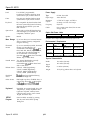
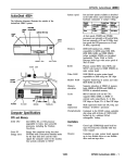
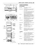
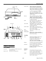
Epson EL 4S/33
System speed
hard disk or diskette
drive bay
To select low speed, press the Ctrl, Alt,
and - keys simultaneously. To select
high speed, press the Ctrl, Alt, and + keys
simultaneously. (Use the - or + key on the
numeric keypad.)
power
button
reset
button
Memory
2MB or 4MB RAM standard on SIMMs;
expandable using 256KB, 1MB, or 4MB
SIMMs to 16MB (maximum); SIMMs must
be 30-pin, fast-page mode type with 70ns
(or faster) access speed
ROM
Phoenix BIOS A386 V1.03; 64KB system
BIOS, video BIOS, and SETUP code
located in EPROM on main system board
Video RAM
256KB DRAM on main system board,
expandable to 512KB or 1MB using 70ns
or 80ns 44256 DIP chips
Shadow RAM
32KB or 64KB, 0 or 1 wait state access
speed; system ROM BIOS and video ROM
can be copied into RAM
Math
coprocessor
Socket for Cyrix Cx83S87-33 math
coprocessor
Clock/calendar
Real-time clock, calendar, and CMOS
RAM socketed on main system board with
built-in battery backup
I
diskette drive
harddisk ‘ght
access light
monitor cable
option
Card
slots
High and low speeds available; high
speed is 33 MHz, low speed is 8 MHz;
speed selection through SETUP program
and keyboard commands; 0 or 1 wait state
memory access selectable through SETUP
Controllers
/
AC inlet
\
Kd I I
I “AA \
I
I
I
COM1 COM2 Parallel
AC outlet
Video
Trident VGA controller on main system
board; provides standard VGA
resolutions with 256KB memory and
extended VGA resolutions up to
1024 x 768 in 16 colors with 512KB
memory and 256 colors with 1MB memory
Diskette
Controller on main system board supports
up to two diskette drives, maximum
Hard disk
Interface on main system board supports
up to two IDE hard disk drives,
maximum, with built-in controllers on the
hard disk drive itself
\
Game
Computer Specifications
CPU and Memory
32-bit CPU
Cyrix Cx486SLC, 33 MHz microprocessor
with 16-bit data bus
Internal cache
1KB built into microprocessor
Interfaces
9/93
Monitor
VGA interface built into main system
board for analog or multifrequency VGA
monitor; 15-pin, D-shell connector
Parallel
One standard B-bit parallel, unidirectional
interface built into main system board;
25-pin, D-shell connector
Epson EL 4S/33-1
Epson EL 4S/33
Serial
Game
Keyboard
Option slots
Two RS-232C, programmable,
asynchronous interfaces built into main
system board; 9-pin, D-shell connectors
Power Supply
Type
65 Watt, fan cooled
One game port interface built into main
system board; 15-pin, D-shell connector
Input ranges
100 to 240 VAC
PS/2 compatible keyboard interface built
into main system board; num lock setting
selectable through SETUP; 6-pin, mini
DIN connector
Maximum
outputs
+5 VDC at 7.5 Amps, +12 VDC at
2.0 Amps, -12 VDC at 0.3 Amps
Frequency
50/60 Hz
Cables
Three 16-bit (or 8-bit) full-length and two
8-bit half-length I/O expansion slots, ISA
compatible, 8 MHz bus speed
One to main system board; four to mass
storage devices
Option Slot Power Limits
Speaker
Internal
Mass Storage
Up to four drives (two horizontal mounts
and two internal mounts), configurable
using the following:
Horizontal
mounts
Internal mount
Maximum current
For all slots
Hard disk
drives
31&nch form factor hard disk drive(s),
third- or half-height size
Other devices
Half-height tape drive, CD-ROM drive, or
other storage device; S!&nch form factor
or 3%~inch form factor with S%nch
mounting frames attached
Keyboard
Detachable, two-position height; 101 or 102
sculpted keys; country-dependent main
typewriter keyboard; numeric/cursor
control keypad; four-key cursor control
keypad; 12 function keys
SETUP
Program
Stored in ROM; accessible by pressing
Ctrl, Alt, and S at the SETUP prompt
during boot
Epson EL 4S/33-2
-12 volts
0.3 Amps
Environmental Requirements
1 Non-operating
1 Operating
range
range
-4° to 140° F
Temperature 41° to 90° F
(-20° to 60° C)
(5° to 32° C)
10% to 90%
20% to 90%
Humidity
(noncondensing)
Altitude
-330 to 9,900 ft
-330 to 39,600 ft
(-100 to 3,000m) (-100 to 12,000m)
Condition
Storage range
-4° to 140° F
(-20° to 60° C)
10% to 90%
-330 to 39,600 ft
(-100 to 12400m)
Physical Characteristics
Two internal third-height (one-inch)
horizontal mounts; bays can
accommodate 3%~inch form factor hard
disk or other drives
5.25-inch, 1.2MB (high-density)
3.5-inch, 1.44MB (highdensity)
5.25-inch, 360KB (double-density)
3.5-inch, 720KB (doubledensity)
+12 volts
1.8 Amps
This system does not support older option cards that may require -5 volts.
Up to two externally-accessible, horizontal
mounts; one horizontal bay can
accommodate a half-height S%inch form
factor hard disk, diskette, tape, CD-ROM,
or other drive; the other horizontal bay
can accommodate one third-height
(one-inch) 3%-inch form factor hard disk,
diskette, tape, or other device
Diskette drives
+5 volts
4.6 Amps
9/93
Width
15.6 inches (396 mm)
Depth
Height
14.5 inches (368 mm)
4.1 inches (104 mm)
Weight
15 lb (6.8 kg) without drives or keyboard
Epson EL 4S/33
Serial Port Connectors (CN4 and CN5)
Major Subassemblies
Serial Port Connector Pin Assignments
Keyboard Connector (CON1)
pin6
pin 5
pin4-w- pin3
pin 2
pin 1
Keyboard Connector Pin Assignments
Pin
1
2
3
Connector Pin Assignments
pin 25
Pin
4
5
6
Signal
+5 VDC
clock
Reserved
VGA Port Connector (CN2)
Parallel Port Connector (CN3)
pin 13
Signal
Data
Reserved
Ground
pin 1
pin 14
VGA Port Connector Pin Assignments
Parallel Port Connector Pin Assignments
‘Active low logic
9/93
Epson EL 4S/33-3
Epson EL 4S/33
Game Port Connector (CN1)
pin 6
System Memory Map
pin 1
000FFFFFFh
System BIOS ROM: 64KB
Duplicated from 0F0000h
pin 15
000FF0000h
pin 9
Reserved for system board: 64KB
Duplicated from 0E0000h
Game Port Connector Pin Assignments
000FE0000h
DMA Assignments
16MB
[Maximum
system
Memory)
Extended memory
00100000h
1MB
System BIOS ROM: 64KB
Default Shadow RAM duplicated at FF0000h
000F0000h
Hardware Interrupts
Unused or I/O expansion ROM: 160KB
Resewed for ROM on I/O adapters
000C8000h
000C0000h
VGA BIOS ROM: 32KB
Default Shadow RAM
000B8000h
VGA text
(color): 32KB
000B0000h
Unused or VGA text
(monochrome): 32KB
video memory: 64KB
Resewed for graphics display buffer
640KB
000A0000h
1 HDD controller
IRQ14
IRQ15 1 Avaiiabie
Conventional system memory: 640KB
Epson EL 4S/33-4
9/93
Epson EL 4S/33
System l/O Address Map
Jumper Settings
Port Jumper Settings
Jumper
number
J2
J10
J11
J15***
J27
off*
Non-interlaced mode
Enables diskette drive controller
Disables diskette drive controller
1-2*
2-3
* Factory setting
** DOS automatically reassigns parallel and serial ports. Check your DOS
manual for mom information.
“‘Two pin jumper
Drive Assignment Jumper Settings
Drive assignment
Upper drive is A
Lower drive is A
J17
2-3
1-2*
J18
2-3
1-2*
J19
2-3
1-2*
J20
2-3
1-2*
* Factory setting
Hard Disk Drive Controller Jumper Settings
Hard disk controller
Enable
Disable
J25
1-2’
2-3
J22**
On*
off
J36**
On*
Off
J37**
On*
Off
* Factory setting
** Two-pin jumper
Built-in VGA Jumper Settings
Built-in VGA
Enable
I Disable
* Factory setting
** Two-pin jumper
To use an external display adapter in an expansion slot, you
must disable the built-in VGA adapter.
9/93
Epson EL 4S/33-5
Epson EL 4S/33
Processor Chips
Hard Disk Drive Types
You can install a Cyrix Cx83S87-33 math coprocessor on the
main system board.
The table below lists types of hard disk drives you can use in
the computer. Check this table and your hard disk manual to
find the correct type number(s) for the hard disk drive(s)
installed in the computer. You need to enter the type
number(s) when you set the hard disk drive configuration in
the SETUP program.
SIMM Installation
The computer comes with 2MB or 4MB of memory installed
on SIMMS. To increase the amount of memory in the
computer up to 16MB, you can install 30-pin, fast-page mode
SIMMs that operate at an access speed of 70ns or faster, with
a capacity of 256KB, 1MB, or 4MB.
Hard Disk Drive Types
The following table shows the possible SIMM configurations;
do not install memory in any other configuration. Make sure
that all SIMMs operate at the same speed.
SIMM Configurations
Video Memory
Your computer has 256KB of video memory. You can install
four or six video DRAM, 20-pin, 70ns or 80ns, 44256 DIP
(Dual Inline Package) chips to increase the video memory to
512KB or 1MB. The following table lists possible video
memory configurations.
Video Memo y Chip Configuration
Bank 0
Soldered
soldered
1 Soldered
Bank 1
Filed
1 Filed
Bank 2
1 Filed
Bank 3
1 Filled
Total
memory
256KB*
512KB
1 1024KB
I
* Standard video memory
Video Memo y and Supported Resolutions
* Actual formatted size may be slightly different than size on drive label.
Epson EL 4S/33-6
9193
Epson EL 4S/33
Software Problems
If the computer has an Epson-supplied hard disk drive,
select a user-defined drive type and enter the appropriate
information from the table below using the SETUP program.
When installing a copy-protected software package, first
try the installation at high speed. If this does not work
properly, select low speed by pressing the Ctrl and Alt
keys and the - key on the numeric keypad
simultaneously. Try loading the program at low speed
and then switching to high speed, if possible.
Epson-supplied Hard Disk Drive Types
Epson drive options
lcyi
IHeadsIRecomplLZ
When using a software package that uses a key disk as its
copy-protection method, try loading it at high speed. If
this does not work, load it at low speed.
Installing Option Cards
Although the EL 4S/33 will support most full-length option
cards, option cards with an I/F connector on the back may
not fit into the option slot.
* Actual formatted size may be slightly different than size on drive label.
Installation/Support Tips
Note that the EL 4S/33 system does not support older option
cards requiring -5 VDC.
Installing Diskette Drives
COM Port Assignment
Make sure that the drive type has been correctly selected in
the SETUP program.
If you want to assign COM1 as COM3, you must set jumper
J10 to position 2-3. You also need to install a special driver
available from Epson technical support.
Installing Hard Disk Drives
It is recommended that a 16-bit, AT-type hard disk
controller be used if you are installing a drive that cannot
use the embedded IDE interface. If you install a non-IDE
hard disk drive and controller card, you need to disable
the built-in IDE hard disk drive interface by moving
jumpers J25 to position 2-3 and J22 to the Off position.
Using IBM 3270/PC 3270 Emulation
If you are using the IBM 3270/PC 3270 Emulation Entry
software, version 2.2, you may see only half the font when
you switch from a terminal emulation session to DOS. Install
the patch program available from the Epson Bulletin Board
at (310) 782-4531.
When installing a hard disk drive, see the hard disk drive
type tables on page 7 and use the SETUP program to
select the correct type number for the drive. You can
select a type number that matches the parameters for the
drive or a type number with parameters having lesser
values, as long as they do not exceed the maximum
capacity (in MB) of the drive. If there is no match for the
drive, you can select a user-defined drive type (48 or 49)
and enter the drive’s exact parameters.
Game Port Problems
Some joysticks may not calibrate properly with certain game
software applications that accept joystick input. If the
joystick connected to the built-in game port does not work
with the game software you are using, try repositioning the
trim knobs on the joystick. If that doesn’t work, you may
want to purchase a joystick option card. If you do, make sure
you set jumper J4 to position 2-3 to disable the built-in game
port.
If you are going to install NetWare 286, version 2.2, install
the IDE.OBJ and IDE.DSK drivers contained within the
IDE286.ZIP file available from Netwire on CompuServe.@
Alternatively, assign the pre-defined hard disk drive type
that most closely matches the drive you are installing
rather than assigning a user-defined drive type.
If you are installing an ESDI hard disk drive, make sure
you disable the built-in IDE hard disk drive interface by
moving jumpers J25 to position 2-3 and J22 to the Off
position. Also be sure to remove the hard disk drive
ribbon connector from the system board.
If you install two hard disk drives in the internal drive
bays, you must use flat-head screws (#6-32UNC x8
FH,M,+) to secure the top drive to the mounting bracket.
You must also replace the existing 65 Watt power supply
with an 85 Watt power supply.
9/93
Epson EL 4S/33-7
Epson EL 4S/33
Information Reference List
Engineering Change Notices
None.
Technical Information Bulletins
None.
Product Support Bulletins
None.
Related Documentation
400251400
TM-EL3/4S33
PL-EL4S33
EPSON EL 4S/33 User’s Guide
EPSON EL 3S/33 and EL 4S/33 Service
Manual
EPSONEL 4S/33 Parts Price List
Epson EL 4S/33-8
9/93