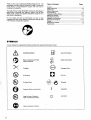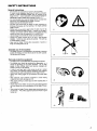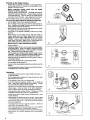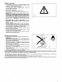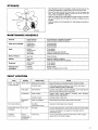
1
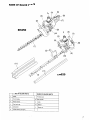
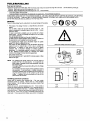
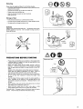
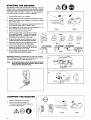
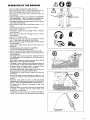
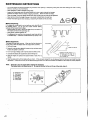
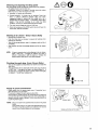
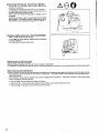
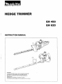
HEDGE TRIMMER
EH 450
EH 620
INSTRUCTION MANUAL
. WARNING:
To reduce the RISK of injury, user must read and understand
the instruction manual before using the Hedge Trimmer.
. Manufacturer reserves the right to change specifications
without notice.
Specifications may differ from country to country.
Do only hand over the Hedge Trimmer together with this manual.
Thank you very much for selecting the MAKITA Hedge Trimmer. We
are pleased to be able to offer you the MAKITA Hedge Trimmer which
is the result of a long development program and many ears of
knowledge and experience.
The Hedge Trimmer models EH450/620 combines the advantages of
state-of-the-art technology with ergonomic design, they are light
weight, handy, compact and represent professional equipment for a
great variety of applications.
For your safety and best tool performance, be sure to read,
understand and follow all the safety and operating procedures listed
in the instruction manual before operation.
Table of Contents
Page
Symbols .......................................................................................... 2
Safety instructions ........................................ !............................... 3-6
Specification ....................................................................................
6
7
Name of major parts ........................................................................
Fuels/Refuelling ...........................................................................8-9
Precautions before starting.........................................................
9-10
Starting the machine ..................................................................... 10
Stopping the machine .......................................................
............. 10
Operation of the machine .................... ........................................... 11
Maintenance instuctions ............................................. ..............12-14
Storage ......................................................................................... 15
Maintenance schedule ............................. ..................................... 15
Fault location .................................................................................
15
SYMBOLS
It is very important to understand the following symbols when reading this instructions manual.
WARN I NG/DANG E R
Fuel and Oil Mixture
Read, Understand and Follow
Instruction Manual
Engine-manual Start
Forbidden
Emergency Stop
No Smoking
First Aid
No Open Flame
Recycling
Protective Gloves must be Worn
Keep the Area of Operation
Clear of All Persons and Pets
Wear Eye and Ear Protection
,
2
I
0
0NETART
OFF/STOP
General Instructions
- This machine can c a u s e serious injuries if used incorrectly.
-
-
TO ensure correct operation, users have to read this instruction
manual to make themselves familliar with the handling of the
Hedge Trimmer. Users insufficiently informed will risk danger to
themselves as well as others d u e to improper handling. (1)
It is recommended only to loan the Hedge Trimmer to people who
have proven to b e experienced with Hedge Trimmers.
Always hand over the instruction manual.
First-time users should ask the dealer for basic instructions to
familiarise themselves with the handling of a n engine powered
Hedge Trimmer.
Children and young persons aged under 18 years must not be
allowed to operate the Hedge Trimmer. Persons over the a g e of
16 years may however u s e the device for the purpose of being
trained only while under the supervision of a qualified trainer.
Use the Hedge Trimmer with the utmost care and attention.
Operate the Hedge Trimmer only if you are in good physical
condition. Perform all work calmly and carefully. The user has
to accept liability for others.
Never u s e the Hedge Trimmer after consumption of alcohol or
drugs, or if feeling tired or ill. (2)
Intended u s e of t h e machine
-
The Hedge Trimmer is only designed for the purpose of trimming
bushes and hedges, and must not be used for any other purpose.
Do Not a b u s e the Trimmer.
Personal protective equipment
-
The blade cover must b e fitted when transporting the machine.
The clothing worn should be functional and appropriate, i.e. it
should b e tight-fitting but not c a u s e hindrance. Do not wear
jewelry or loose clothing which could become entangled with
bushes or shrubs, or the machine.
- In order to avoid eye, hand or foot injuries as well as to protect
your hearing, the following protective equipment and protective
clothing must be used during operation of the Hedge Trimmer.
- Always wear safety goggles for e y e protection that meets ANSI
287.1.
- Wear adequate noise protection equipment to avoid hearing
impairment, e a r muffs, ear plugs, etc. (3)
- Wear proper clothing to protect legs and other exposed parts of
(3)
your body. (4)
- Gloves m a d e of thick leather are part of the prescribed equipment
and must always b e worn during operation of the Hedge Trimmer.
(4)
- When using the Hedge Trimmer, always wear sturdy s h o e s with a
non-slip sole. This protects against injuries and ensures a good
footing. (4)
3
Starting up the Hedge Trimmer
Please make sure that there are children or other people within a
working range of 50 feet or 15 meters (5),also pay attention to any
-
animals in the working vicinity
Before operating, always c h e c k that t h e Hedge
Trimmer is s a f e for operation:
Check the security of the throttle lever. The throttle lever should be
checked for smooth and easy action. Check for proper functioning
of the throttle lever lock. Check for clean and dry handles and test
the function of the STOP switch. Keep handles free of oil and fuel.
Start t h e Hedge Trimmer only in accordance with the instructions.
Do not u s e any other methods for starting the engine (6)l
Use the Hedge Trimmer only for applications specified.
Start the Hedge Trimmer enjine only after the entire assembly is
done. Operation of the Hedge Trimmer is permitted only after all
t h e appropriate accessories a r e attached!
Before starting, make sure that the cutter blade will not contact
any objects such as branches, stones, elc.
T h e engine is to b e stopped immediately if there a r e any engine
problems.
When working with the Hedge Trimmer, keep both hands on
handles always wrap your fingers tightly around the handle,
keeping the control handle cradled between your thumb and
forefinger, Keep your hand in this position to have your machine
under control a t all times. Make sure your control handle is in
good condition and free of moisture, pitch, oil or grease.
Always e n s u r e a safe, well-balanced footing
Only use outdoors.
Operate the Hedge Trimmer in such a manner as to avoid inhalation
of the exhaust gases. Never run the engine in enclosed rooms (risk
of suffocation and gas poisoning). Carbon monoxide is a n odorless
gas. Always ensure there is adequate ventilation.
Stop the engine when resting and when leaving the Hedge Trimmer
unattended. Place it in a safe location to prevent danger to others,
setting fire to combustible materials or damage to the machine.
- Never lay down the hot Hedge Trimmer onto dry grass or onto any
combustible materials.
Never operate the engine with a faulty exhaust muffler.
- Stop the engine during transport (7).
Secure the tool properly before transporting in vehicle to avoid fuel
leakage.
W h e n transporting the Hedge Trimmer ensure that the fuel tank is
completely empty to avoid fuel leakage.
-
-
I
-
-
_
_
_
-
-
-
-
-
-
Refuelling
- To reduce t h e risk of fire and bum injury; handle fuel with care. It
is highly flammable.
- Stop the engine before refuelling (7), keep well away from open
flame (8) and do not smoke.
- Do not attempt to refuel a hot or a running engine.
- Avoid skin contact with petroleum products. Do not inhale fuel
-
-
-
vapor. Always wear protective gloves during refuelling. Change
and clean protective clothing at regular intervals.
Take care not to spill either fuel or oil always wipe unit dry before
starting engine. Allow wet cloths to dry before disposing in
proper, covered container to prevent spontaneous combustion.
Avoid any fuel contact with your clothing. Change your clothing
immediately if fuel h a s been spilled on it (danger hazard).
Inspect the fuel c a p at regular intervals making sure that it stays
securely fastened.
Carefully tighten the locking screw of the fuel tank. Move at lease
10 ft (3meters) away from the refuelling point before starting engine.
Never refuel in closed rooms. Fuel vapors accumulate a t ground
level (risk of explosions).
Only transport and store fuel in approved containers. Make sure
stored fuel is not accessible to children.
When mixing gasoline with two-cycle engine oil, use only gasoline
which contains no ethanol or methanol (types of alcohol).
This will help to prevent damage to fuel lines and other engine parts.
Make sure the unit is properly assembled and in good operating
condition.
,
4
'-
'
0
STOP
Resting
Transporting
Refuelling
Maintenance
Tool Replacement
(7)
n-1\
w
I
'I
I
Method of operation
- Use the Hedge Trimmer only in good
light and visibility. During
cold s e a s o n s beware of slippery or wet areas, ice and snow (risk
of slipping). Always ensure a safe footing.
Do not overreach or stand on unstable support. Keep good
footing and balance a t all times.
- Keep both feet on the ground.
- Never stand on a ladder and the Hedge Trimmer.
- Never climb up into trees to perform cutting operation with the
Hedge Trimmer.
- DANGER-CUT HAZAARD-KEEP HANDS AWAY FROM BLADES.
Don’t feed twigs or other material to b e cut into the blade with your
hands or reach over the moving blade to pick up clippings. Never
grasp the exposed cutting blades or cutting edges when picking up
or holding the tool. CAUTION-Blade may coast after its turned
-
-
Off.
KEEP HANDS AND ALL PARTS OF BODY AWAY from blade.
The e d g e s are sharp and can c a u s e injury even when the tool is
“OFF
- BEFORE TRIMMING, inspect a r e a s for wires, cords, glass or
other foreign objects which could c o m e in contact with the blade.
- Keep both hands on the handles when operating a Hedge Trimmer,
Never grasp exposed cutting blades of Hedge Trimmer.
- Make sure engine is stopped and blades have stopped moving
before clearing jammed material.
- Be aware of any and all electric lines and electric fences. Check
all a r e a s for electrical lines before cutting.
- To reduce the risk of stumbling and loss of control, do not walk
backward while operating the machine.
Maintenance instructions
Always stop the engine before cleaning or servicing the unit or
-
replacing parts.
- MAINTAIN TOOL WITH CARE. Keep cutting edges sharp and
clean for best and safest performance. Follow instructions for
lubricating and proper maintenance.
- Be kind to the environment. Operate the Hedge Trimmer with as
little noise and pollution as possible. In particular check the
correct adjustment of the carburetor.
- Clean the Hedge Trimmer at regular intervals and check that all
screws and nuts are securely tightened.
- Never service or store the Hedge Trimmer in the vicinity of open
flames, sparks, etc. (11).
- Always store the Hedge Trimmer in a well-ventilated locked room
and with a n emptied fuel tank out of reach of children.
Observe and follow all relevant accident prevention instructions issued by the trade associations safety boad and by insurance companies.
Do not perform any modific;rtions to the Hedge Trimmer a s this will risk your safety.
The performance of maintenance or repair work by the user is limited to those activities as described in this instruction manual. All other work is
to be done by Makita authorized or Factory Service Centers.
Use only genuine spare parts and accessories supplied by MAKITA authorized or factory service centers.
Use of non-approved accessories and tools means increased risk of accidents and injuries. MAKITA will not accept any liability for accidents or
damage caused by the use of any non-approved accessories.
First aid
In case of a n accident make sure that a well-stocked first-aid kit
according to DIN 13164, is available in the vicinitv of the cuttina
operations.
Immediately replace any item taken from the first aid kit.
-
I
Packaging
The MAKITA Hedge Trimmer is delivered in a protective cardboard
box to prevent shipping damage. Cardboard is.a basic raw material
and is therefore consequently reusable or suitable for recycling
(waste paper recycling).
SPECIFICATION
Model
Dimensions (L x W x H)
mm
Mass (with blade cover)
kg
EH450
EH620
964 x 244 x 218
1,063 x 288 x 218
4.4
4.5
Volume (fuel tank)
cm3
0.4
Engine displacement
cm3
20.0
Cutting length
mm
Maximum engine performance
Maximum blade speed
620
450
kw
0.61
mls
1.8
Idling speed
llmin
3,000
Clutch engagement speed
llmin
4,000
~
Carburetor type
type
WALBRO WYL
Ignition system
type
Solid ignition system
Spark plug
Electrode g a p
type
mm
.
0.3
0.7
Mixture ratio (fuel : MAKITA 2-stroke oil)
50 : 1
Gear ratio
8 : 34
1) T h e data takes equally into account idling and racing speed operating modes.
,
6
-
NGK-BM4A
I
'-
NAME OF MAJOR PARTS
EH450
EH620
NAME OF MAJOR PARTS
NAME OF MAJOR PARTS
1
Blade
7
Throttle lever
2
Front handle
8
Rear handle
3
Recoil starter
9
Muffler
Fuel tank cap
10
Gearbox
5
Carburetor
11
Blade cover
6
STOP Switch (ON-OFF)
4
..
7
FUELSIREFUELLING
Fuel and oil mirture
Inspect the fuel tank and fill with clean, fresh fuel of the proper mixture to assure the longer life of the tool. Use the following mixed gas.
Gasoline : Makita genuine two-stroke engine oil = 50 : 1 or
Gasoline : Other manufacturer’s two-stroke engine oil = 25 : 1 recommended
FOR CALIFORNIA REGULATION :
THIS EQUIPMENT IS CERTIFIED TO OPERATE ON GASOLINE + TWO-STROKE ENGINE OIL
WHEN MIXING GASOLINE WITH TWO-STROKE ENGINE OIL, USE ONLY GASOLINE WHICH CONTAINS NO ETHANOL OR METHANOL
V P E S O F ALCOHOL). THIS WILL HELP TO AVOID POSSIBLE DAMAGE TO ENGINE FUEL LINES AND OTHER ENGINE PARTS.
DO NOT MIX GASOLINE AND OIL DIRECTLY IN THE FUEL TANK.
IMPORTANT:
Failure to follow proper fuel mix instructions may cause damage to the engine.
-
-
-
The engine of the hedge Trimmer is a high-efficiency two-stroke
engine.
It is run with a mixture of fuel and two-stroke engine oil. The
engine is designed for unleaded regular fuel with a min. -octane
value of 91 ROZ.
In case no such fuel is available, you can use fuel with a higher
octane value. This will not damage the engine, but may cause
poor operating behaviour.
A similar situation will arise from the use of leaded fuel.
To obtain optimum engine operation and to protect your health and
the environment, only unleaded fuel should be used!
For lubricating the engine u s e a two-stroke engine oil (quality
grade:TC-3), which is added to the fuel.
The engine has been designed for use with MAKITA two-stroke
engine oil and a mixture ratio of 50:l only to protect the
environment. In addition, a long service life and a reliable
operation with a minumum emission of exhaust g a s e s is
guaranteed. It is absolutely essential to observe a mixture ratio
of 50:l (MAKITA 2-stroke engine oil), otherwise the reliable
function of the Hedge Trimmer cannot be guaranteed.
The correct mixture ratio:
Mix 50 parts gasoline with 1 part MAKITA 2-stroke engine oil (See
table on the right)
NOTE
For preparing the fuel-oil mixture, first mix the entire oil
quantity with half o the fuel required. In a n approved can
which meets of exceeds all local code standards, then add
the remaining fuel.
Thoroughly shake the mixture before filling it into the Hedge
Trimmer’s tank.
It is not wise to add more engine oil than specified to ensure
safe operation. It will only result in a higher production of
combustion residues which will pollute the environment and
clog the exhaust channel in the cylinder as well as the
muffler. In addition, the fuel consumption will rise and the
performance will decrease.
Handling petroleum products
Utmost care is required when handling fuel. Fuel may contain
substances similar to solvents. Refuel either in a well ventilated
area or outdoors. Do not inhale fuel vapors, avoid any contact of fuel
or oil with your skin.
Mineral oil, fuel, etc., product degrease your skin. If skin comes in
contact with these substances repeatedly or for an extended period of
time, various skin diseases may result. In addition, allergic reactions
are known to occur. Eyes can be irritated by contact with oil, fuel etc.
If oil, fuel, etc., comes into your eyes, immediately wash them with
clear water. If your eyes are still irritated, see a doctor immediately!
8
I
A
Observe the Safety Instructions on page 4
Gasoline
50:1
1 GAL
2.6 OZ
2 GAL
6.4 OZ
1
Refuelling
Always stop the engine and allow it to cool before refuelling.
- Thoroughly clean the around the fuel filler cap to prevent dirt from
getting into the fuel tank.
- Unscrew the fuel filler c a p and fill the tank with fuel.
- Tightly screw on the fuel filler cap.
- Clean the fuel filler c a p and tank after refuelling!
Wipe up any fuel
Storage of fuel
- Fuel cannot be stored for a n unlimited period of time.
- Purchase only the quantity required for a 4 week operation period.
- Use approved fuel storage containers only.
WARNING!
Gasoline is a n extremely flammable fuel. Use extreme caution when
handling gasoline or fuel mix. Do not smoke or bring any fire or
flame near the fuel.
I
I
PRECAUTIONS BEFORE STARTING
- Please make sure that there a r e no children or other people within
a working range of 15 meters or 50 feet, also pay attention to any
animals in the working vicinity.
- Before u s e always check that the Hedge Trimmer is safe for
operation. Check the cutting device is not damaged, the control
lever for e a s y action and check for proper function of the STOP
switch.
Rotation of the cutting device during idling speed is not allowed.
Check with your dealer for adjustment if in doubt. Check for
clean and dry handles and test function of the STOP switch.
- Start the Hedge Trimmer only in accordance with the instructions.
Do not u s e any other methods for starting the engine. (See
Starting)
- Start the hedge Trimmer engine'only after the entire assembly is
done. Operation of the engine is only permitted after all the
appropriate accessories are attached. Otherwise there is a risk
of injury.
- Before starting, make sure that the cutting device h a s no contact
with objects such as branches, stones, etc.
- Before trimming, inspect a r e a for wires, cords, glass, or other
foreigh objects which could c o m e in contact with the blade.
Electrical shock. Be aware of any and all electric lines and electric
fences. Check all areas for electrical lines before cutting.
-
Diagrammatic figure
,'
I
360"
-:
15 meters
(50 feet)
I
--___--
Q -I
&%-e
9
STARTING THE MACHINE
Move a t least 3 meters away from the place of refuelling. Place the
Hedge Trimmer on a clean a r e a of ground make sure that the cutting
tool d o e s not c o m e into contact with the ground or any other objects.
Cold starting (When t h e engine is cold or it h a s been stopped for
more than 5 minutes or when fuel is added to the engine.
1. Push the STOP switch (1) to "I" position.
2. Squeeze first the lock lever A and then the throttle lever B. (fig.1)
3. Keeping the throttle lever B depressed, then press the throttle
lock C inward. (fig. 2)
4. Keeping throttle lock C depressed, release the throttle lever B.
this will lock the throttle lever B in position. (fig. 3)
5. Give a gentle push o n the primer pump (2) repeatedly (7 to 10
times) until fuel c o m e s into the primer pump.
6. Move the choke lever (3)to position(1-1).
7. Hold the unit down firmly so you will not lose control
while cranking the engine. If not held down properly,
the engine could pull you off balance or swing the
cutting blade into a n obstruction or your body.
8. Slowly pull the starter grip until resistance is felt and
continue with smart pull until initial ignition a r e heard.
9. Depress the choke lever (3)to the position (I I ) and
pull the starter rope again until the engine starts.
10. As soon as the engine starts, immidiately tap and
release the throttle, thus releasing the half-throttle
rock so that the engine can run in idle.
11. Run the engine for approximately one minute at a
moderate speed before aplying full speed.
I
a/
Do not pull the starter rope to its full extent and do not
allow the starter grip to be retracted without control,
ensure that it is retracted slowly.
1. Release the throttle lever completely.
2. Push the 1-0switch (on/off switch) to
"0"position, the engine rotation will become
low and the engine will stop.
in
EH450
(fig. 1)
Hot staring: (Restarting immediately after the engine h a s stopped)
When restarting a hot engine, first try the above procedure: 1, 5 , 7 , 8 .
If the engine d o e s not start, repeat above s t e p s 1-11.
STOPPING THE MACHINE
s@
EH620
,
(fig. 2)
+
Note:
EH450
G
l
(fig. 3)
OPERATION OF THE MACHINE
-
Be sure to carefully read and follow safety instructions.
- Keep hands away from blades. Never grasp the exposed cutting
blade or cutting edges, when picking up or holding the tool.
- Never touch the cutting device when starting the engine and
-
-
-
-
-
-
during operation.
Operate the Hedge Trimmer in such a manner as to avoid inhalation
of the exhaust gases. Never run the engine in enclosed rooms
(Risk of g a s poisoning). Carbon monoxide is a n odorless gas.
All protective installations and guards supplied with the machine
must be used during operation.
Never operate the engine with a faulty exhaust muffler or if it is
missing.
Use the Hedge Trimmer only in good light and visibility.
Always ensure a safe footing.
Never stand on a ladder and run the Hedge Trimmer. Keep both
feet on the ground.
Never climb up the trees with the Hedge Trimmer to perform
cutting operation.
Never work on unstable surfaces.
Remove sand, stone, nails, wire, etc. found within the working
area. Foreign objects may damage the cutting blades.
Before commencing cutting, the cutting blades must have reached
full working speed.
Always hold the Hedge Trimmer firmly with both hands on the
handles only.
The right hand grips the front handle of model EH620.
This is the way to safely operate the machine.
Use a firm grip with thumbs and fingers encircling the handles.
When you release the throttle, it takes a few moments before the
cutting blades stop.
The Hedge Trimmer must not b e used for cutting with fast idle.
The cutting speed cannot b e adjusted with the throttle control in
fast idle position.
When cutting a hedge, the machine should be held so that the
blades form a 15-30" angle with the cutting line.
If the Hedge Trimmer is used with circular movements against the
e d g e of the hedge, the twigs will be thrown directly to the ground.
At vertical cutting, the Hedge Trimmer is used with circular
pendulation, swinging up and down close to the hedge.
Pay special attention when cutting hedges which a r e laid out a
long a wire-fence and have grown through the fence.
The blade must not contact the fence, otherwise the blades may
be destroyed.
Do not u s e the Hedge Trimmer continuously for a long time. It is
normal to take a break of 10 to 2 0 minutes after every 50 minutes
operation.
Should the cutting blades hit stones or other hard objects,
immediately switch off the engine and inspect the cutting blades for
damage. Replace damaged blades before re-commencing work.
T h e engine must be switched off immediately in case of any
engine problems.
Operate the Hedge Trimmer with as little noise and contamination
as possible. In particular check the correct setting of the
carburetor and the fuel/oil ratio.
Do Not attempt to remove jammed cut material when blades are
running. Put unit down, turn it off, and remove necessary cuttings.
h
77
MAINTENANCE INSTRUCTIONS
-
-
Turn off the engine and remove the spark plug connector when replacing or sharpening cutting tools, also when cleaning the cutter or cutting
device or carrying out any maintenance.
Never straighten or weld a damaged cutting blade.
Inspect the cutting blades with the engine switched off at short, regular intervals for damage.
(Detection of hairline cracks by means of tapping-noise test.) Beware the teeth are sharp.
Clean the Hedge Trimmer at regular intervals and check that all screw and nuts are well tightened.
Never service or store the Hedge Trimmer in the vicinity of naked flames to avoid fires.
Always wear leather gloves when handling or sharpening the blades as they are sharp.
Blade sharpening
If the e d g e s are rounded and do not cut well any more, grind off only
the shaded portions. Do not grind the contact surfaces (sliding
surfaces) of the top and bottom edges.
Before grinding, be sure to secure the blade firmly and switch off
-
-
the engine and remove the spark plug cap.
Wear gloves, protective glasses, etc.
An edge ground too much at a time or ground many times will lose
its hardened layer. It becomes rounded and dull very quickly in use.
Blade adjustment
The blades will wear with long use. When you find that trimming is
not as good as when the blades were new, adjust them as follows
1. Turn nut Q loose.
2. Screw Q in with the driver lightly till it stops turning, and then screw
it back one quarter to a half turn.
3. Turn nut Q tight, holding screw Q at the s a m e time with a driver.
Holding :he dirk grinder at a
4. Lubricate the blades after adjustments above with light oil.
45' angle. grind :he edge off
to rho dotted line to sharpen
5. Start the engine and operate the engine throttle on and off for a
the rounded :ip.
minute.
6. Stop the engine and touch the blades with your hand . If they are warm enough for you to keep your hand on, then you have made the proper
adjustment. If they are too hot for you to keep touching, give screw .Q a little more turnback and repeat 5 to see if they are properly adjusted.
NOTE
Never fail to stop the engine before maklng the adjustment.
The blades have a slot around screw Q. In case you find dust In the end of any of the slots, clean it.
Q Hexagonal U nut
Q Trussscrew
0 Flat washer
8 Blade guide
0 Upper Blade
8 Lower blade
12
Checking and adjusting t h e idling s p e e d
The cutting blade should not when the control lever is fully released.
- Idle speed should be s e t to 2,600 rpm.
If necessary, correct it by means of the idle screw (the cutting
blade must not run when the engine is on idle).
Clockwise : for faster rate of revolution
Counter-clockwise : for slower rate of revolution Check that
there is sufficient difference between idling and clutch
engagement speed to ensure that the cutting tool is at a
standstill while the engine is idling. (If necessary, reduce idling
speed.) If the tool still continues to run under the idling
conditions, consult your nearest authorized service agent.
The clutch should engage at minimum 3,250 rpm.
Check the functioning of the STOP switch, the lock-off lever, the
control lever, and the lock button.
-
Cleaning of air cleaner Every 8 hours (Daily)
Remove the air cleaner cover.
-
-
Push the choke lever up (arrow), to prevent dirt particles from
entering the carburetor.
Take out the sponge element, wash it in lukewarm water and dry it
completely.
After cleaning, put back the sponge element and the air cleaner
cover.
NOTE
If there is excessive dust or dirt adhering to the air cleaner,
clean it every day. A clogged air cleaner may make it
difficult or impossible to start the engine or increase the
.
engine rotation speed which could c a u s e damage.
-
Checking the spark plug Every 8 hours (Daily)
- Only u s e the supplied universal wrench to remove or to install the
spark plug.
- The g a p between the two electrodes of the spark plug should be
0.6 to 0.7mm. If the g a p is too wide or too narrow, adjust it. If
the spark plug is clogged with carbon or fouled, clean it thoroughly
or replace it. Use a n exact replacement.
0,6 - 0,7 mm
Supply of g r e a s e and lubricant
- Supply grease from the grease nipple every 15 operating hours.
(Shell Alvania No.3 or equivalent)
The amount of grease for each supply is about 20cc.
(Once grease is supplied regularly as mentioned above, grease will
come out from the end of the gear case (root of the cutting edge) in
operation just after supply of grease. Confirm this phenomenon as
a guide to grease supply.)
NOTE: Be sure to observe the specified time and amount of grease
supply.
If the grease supply is not made at the specified interval or if
the amount of grease supplied is not sufficient, the machine
may fall into a trouble because of lack of grease.
An\
Grease will come out from here.
7 .?
-
Suction head in the fuel tank Every 50 hours (Monthly)
The felt filter (1) of the suction head is used to filter the fuel
-
-
required by the carburetor.
A periodical visual inspection of the felt filter is to be conducted.
For that purpose, open the tank cap, u s e a wire hook and pull out
the suction head through the tank opening.
Filters found to have hardened, been polluted or clogged up are to
be replaced.
Insufficientfuel supply can result in the admissible maximum speed
being exceeded. It is therefore important to replace the felt filter at
least quarterly to ensure satisfactory fuel supply to the carburetor.
-
Cleaning of muffler exhaust port Every 50 houR 0
-
Check of muffler exhaust port (2) regularly.
If it is clogged by carbon deposits, carefully scratch the deposits
out with a suitable tool.
Do not allow carbon to fall into engine ports.
Replace fuel lines: Every 200 hours (yearly)
Overhaul engine: Every 200 hours (yearly)
Replace packings and gaskets with new ones: Every time engine is reassembled.
Any maintenance or adjustment work that h a s not been included and described in this manual is only to be performed by Authorized Service Agent.
Daily c h e c k u p and m a i n t e n a n c e
To ensure a long service life and to avoid any d a m a g e to the equipment, the following servicing operations should be performed a t regular intervals.
- Before operation, check the machine for loose screws or missing parts. Pay particular attention to the tightness of the cutter blade screws. Every 8 hours (Daily)
- Before operation, always check for clogging of the cooling air passage and the cylinder fins. Clean them if necessary. - Every 8 hours (Daily)
- Perform the following work daily after use:
Clean the Hedge Trimmer externally and inspect for damage.
Clean the air filter. When working under extremely dusty conditions, clean the filter several times a day.
Check the blades for d a m a g e and make sure they a r e firmly mounted.
14
STORAGE
n
I
- When keeping the machine in storage for a long,time, drain fuel from the
fuel tank and carburetor, as follows: Drain all fuel from the fuel tank.
- Remove the spark plug and add a few drops of oil into the spark plug
hole. Then, pull the starter gently to confirm that oil film covers the
engine inside and tighten the spark plug.
- Clear dirt or dust from the cutter blade and outside of engine, wipe them
with a oil-immersed cloth and keep the machine a t a place as dry as
possible.
- Abide by Federal and Local regulations for safe storage and handling of
gasoline.
1
MAINTENANCE SCHEDULE
I
General
Engine assembly,
screws and nuts
1
Visual inspection for damage and tightness
Check for general condition and security
After e a c h refuelling
Throttle lever
Safety lock key
STOP switch
Functional check
Functional check
Functional check
Daily
Air filter
Cooling air duct
Cutting tool
Idling speed
To be cleaned
To be cleaned
Check for damage and sharpness
Inspection (cutting tool must not move)
Every 15 hours
Weekly
Quarterly
Shuting down
procedure
I
I
r
Gearcase
Spark plug
Muffler
I
1
Suction head
Fuel tank
supply of grease
Inspection, replace if necessary
Check and if necessary clean the oDenina
To be replaced
To be cleaned
Empty fuel tank
Operate until engine runs out of fuel
Fuel tank
Carburetor
FAULT LOCATION
Fault
System
Engine not starting
or under difficulties
Ignition system
0bservat ion
Cause
Ignition spark is present
Faulty fuel supply or compression system, mechanical defect
No ignition spark
STOP-switch operated, wiring fault or short circuit, spark plug or
connector defective, ignition module faulty
Fuel supply
Fuel tank filled
Incorrect choke position, carburetor defective, suction head (gas line
filter) dirty, fuel supply line bent or interrupted
Compression
Inside of engine
Cylinder bottom gasket defective, crankshaft seals damaged,
cvlinder or Diston rinas defective
I Outside of engine
Mechanical
fault
Warm start problems
Engine starts but dies
immediately
Fuel supply
Insufficient
performance
Several
systems may
simultaneously
be affected
I
~~
Improper sealing of spark plug
Starter not engaging
Broken starter spring, broken parts inside of the engine
Tank filled
Ignition spark existing
Carburetor contaminated, have it cleaned
Tank filled
Incorrect idling adjustment, suction head or carburetor contaminated
-
Engine idling
Fuel tank vent defective, fuel supply line interrupted, cable or
STOP-switch faulty
Air filter contaminated, carburetor contaminated, muffler clogged,
exhaust duct in the cylinder clogged
I
1
California Emission Control Warranty Statement
[This warranty d o e s not apply in any other state.]
YOUR WARRANTY RIGHTS AND OBLIGATIONS
The CaliforniaAir Resources Board and Makita U.S.A., Inc. are pleased to explain
the emission control warranty on your 7995 and later utility and/or lawn and garden
equipment engine. In California,new utility and lawn and garden equipment engine
must be designed, built and equipped to meet the State’s stringent anti-smog
standards. Makita U.S.A., Inc. must warrant the emission control system on your
utility and/or lawn and garden equipment engine for the periods of time listed below
provided there has been no abuse, neglect or improper maintenance of your utility
and/or lawn and garden equipment engine.
Your emission control system includes parts such as the carburetor or fuel injection
systems, the ignition system and the catalytic converter. Also included are the
hoses and connectors and other emission-related assemblies.
Where a warrantable condition exists, Makita U.S.A., Inc. will repair your utility
and/or lawn and garden equipment at no cost to you including diagnosis, parts and
labor.
MANUFACTURER’S WARRANTY COVERAGE:
The 7 995 and later utility and/or lawn and garden equipment engines are warranted
for two years. I f any emission-related part on your engine is defective, the part will
be repaired or replaced by Makita U.S.A., Inc.
OWNER’S WARRANTY RESPONSIBILITIES:
As the utility and lawn and garden equipment engine owner, you are responsible for
the performance of the required maintenance listed in your owner’s manual.
Makita U.S.A., Inc. recommends that you retain all receipts covering maintenance
on your utility and/or lawn and garden equipment engine, but Makita U.S.A., Inc.
cannot deny warranty solely for the lack of receipts or for your failure to ensure the
performance of all scheduled maintenance.
As the utility and/or lawn and garden equipment engine owner, you should be
aware, however, that Makita U.S.A., Inc. may deny you warranty coverage if your
utility and/or lawn and garden equipment engine or a part has failed due to abuse,
neglect, improper maintenance or unapproved modifications.
Your are responsible for presenting your utility and/or lawn and garden equipment
engine to a Makita U.S.A., Inc. service center as a problem exists. The warranty
repairs should be completed in a reasonable time, not to exceed 30 days.
I f you have any questions regarding your warranty rights and responsibilities, you
should contact a Makita Factory Service Center Manager nearest you. A list of the
Factory Service Center locations and phone numbers is provided on page 20 for
your convenience.
LIMITED WARRANTY
California Only
-
-
Makita U.S.A., Inc. a distributor of utility and lawn and garden equipment in the U.S.,
warrants to the owner of 1995 and later utility and/or lawn and garden equipment
engines that the engine (1) h a s been designed, built, a n d equipped a t the time of
manufacture so as to conform with the applicable regulations of the California Air
Resources Board, and (2) is free from defects in materials and workmanship which
may c a u s e it to fail to conform with those regulations as applicable according to the
terms and conditions stated below.
WARRANTY PERIOD
The warranty period begins on the date which the utilrty and/or lawn and garden
equipment engine is delivered to the original retail purchaser and ends two years after
that date. During this two year period Makita U.S.A., Inc. warrants to the original retail
purchaser and each subsequent purchaser that the engine is free from defect in material
and workmanship that can cause the failure of a warranted emission-related part.
WHAT IS COVERED UNDER THIS WARRANTY
Repair and/or replacement of any warranted emission-related part will be performed
a t no charge provided the work is performed a t a n authorized warranty station. There
will also be no charge for any diagnostic labor performed a t a n authorized warranty
station which leads to the determination that a warranted emission-related part is
defective.
Any warranted part which is not scheduled for replacement as required maintenance,
or which is scheduled only for regular inspection to the effect of “repair or replace as
necessary” shall b e warranted for the warranty period. Any warranted part which is
scheduled for replacement as required maintenance shall be warranted for the period
of time up to the first scheduled replacement of the part. This warranty shall apply
only towards the repair, replacement, and/or adjustment of the component parts listed
below.
EMISSION-RELATED PARTS COVERED UNDER THIS WARRANTY
Fuel Metering Systems
(a) Carburetor a n d its internal parts
(b) Air cleaner plate
(c) Air cleaner case
(d) Air cleaner element
(e) Fuel filter
2. Ignition Systems
(a) Spark Plug
(b) Flywheel Magneto
(c) Ignition Coil
3. Other Miscellaneous Items Used in Above Systems
(a) Fuel Hoses
(b) Sealing Gaskets
If it is determined by a n authorized warranty station that other engine components have
been damaged due to the failure of a warranted emission-related part during the warranty
period, Makita U.S.A., Inc. will repair and/or replace the necessary components.
I.
,
’
WHAT IS NOT COVERED UNDER THIS WARRANTY
This warranty does not cover any emission-related part which malfunctions, fails, or
is damaged d u e to alterations and/or modifications such as changing, adding, or
removing parts.
When a n engine is being serviced under warranty, Makita U.S.A., Inc. and a n y of its
authorized dealers, distributors, or warranty stations shall not be liable for any loss
of u s e of the engine, for any damage to goods, or loss of time or inconvenience.
This limited warranty also does not apply to any emission-related part which
malfunctions, fails, or is damaged d u e to failure to follow the maintenance and
operating instructions specified in the 1995 and later Owner’s Manual including:
(a) Improper or inadequate maintenance of any warranted emission-related part.
(b) Improper installation, adjustment, or repair of the engine or any warranted
emission-related part unless performed by a factory authorized warranty station.
(c) Failure to u s e recommended fuel as specified in the 1995 and later Owner’s
Manual.
(d) Repairs and diagnosis performed outside of a n authorized warranty station.
(e) Use of parts which are not authorized by Makita U.S.A., Inc.
MAINTENANCE SCHEDULE
The engine owner is responsible for having all scheduled inspection a n d
maintenance services performed at the intervals specified in the 1995 and later
Owner’s Manual a n d to retain records of t h e s e services as having been performed.
These records should be transferred to each subsequent owner of the engine.
Makita U.S.A., Inc., cannot deny a claim solely because there a r e no records of
scheduled maintenance; however, a warranty claim may be denied if the failure to
perform the scheduled maintenance and inspection resulted in the failure of a
warranted emission-related part. As a minimum, the engine owner is responsible
for t h e scheduled inspection and maintenance described below which a r e based on
the procedures described in the Owner’s Manual.
INTERVAL
(a)Check all nuts and bolts and tighten as necessary
Every 8 hours of use or daily.
(b) Check air passages and engine cylinder fins for clogging. Every 8 hours of use or daily.
PROCEDURE
-
Remove all obstructions as necessary.
(c) Clean air cleaner.
(d) Check the spark plug. Clean and adjust it if necessary.
(e)Check the muffler exhaust port. Clean it if necessary.
(9 Check the fuel filter. If clogged, replace it with new filter.
(9) Replace fuel lines.
(h) Overhaul the engine.
(i) Replace the packings and gaskets.
,
IQ
Every 8 hours of use or daily.
Every 8 hours of use or daily.
Every 50 hours of use or monthly.
Every 50 hours of use or monthly.
Every 200 hours of use or annually.
Every 200 hours of use or annually.
Every time the engine is reassem bled.
REPAIR AND REPLACEMENT OF EMISSION-RELATED PARTS
It is recommended that only engine replacement parts which have been authorized
a n d approved by Makita U.S.A., Inc. should be used in the performance of any
warranty maintenance or repairs of emission-related parts. T h e s e replacement
parts will b e provided a t no charge if the part is still under warranty.
HOW TO FILE A WARRANTY CLAIM
AND WHERE TO GET WARRANTY SERVICES
Contact the nearest Makita Factory Service Center Manager to determine the appropriate
location where the required warranty services are to be performed. A list of the Factory
Service Center locations and phone numbers are provided below for your convenience.
14930 Northam Street
La Mirada, CA 90638-5753
(714) 522-8088
41 850 Christy Street
Fremont, CA 94538-5107
(510) 657-9881
Clovis Ave., Ste. 112
Fresno, CA 93727
(209) 252-5166
7674 Clairemont Mesa Blvd.
S a n Diego, CA 921 11
(619) 278-4471
1440 South “E” Street
S a n Bernardino, CA 92408
(909) 885-1289
1714 E McFadden Ave., Unit M
S a n t a Ana, CA 92705
(714) 667-5066
16735 Saticoy St., Ste. 105
Van Nuys, CA 91406
(818) 782-2440
1565 Winchester Blvd.
Campbell, CA 95008-0501
(408) 379-0377
1421N.
1970 Fulton Avenue
Sacramento, CA 95825
(916) 482-5197
FEDERAL EMISSION COMPONENT DEFECT WARRANTY
EMISSION COMPONENT DEFECT WARRANTY COVERAGE - This emission
warranty is applicable in all States, except the State of California
Makita U.S.A., Inc., La Mirada, California, (herein “MAKITA) warrant to the initial retail
purchaser and each subsequent owner, that this utility equipment engine (herein
“engine”) w a s designed, built, and equipped to conform at the time of initial sale to all
applicable regulations of the U.S. Environmental Protection Agency (EPA), and that the
engine is free of defects in materials and workmanship which would c a u s e this engine
to fail to conform with EPA regulations during its warranty period.
For the components listed under PARTS COVERED, Makita Factory Service Center or
service center authorized by MAKITA will, a t no cost to you, make the necessary
diagnosis, repair, or replacement necessary to ensure that the engine complies with
applicable U S . EPA regulations.
EMISSION COMPONENT DEFECT WARRANTY PERIOD
The warranty period for this engine begins on the date of sale to the initial purchaser
and continues for a period of 2 years.
PARTS COVERED
Listed below are the parts covered by the Emission Component Defect Warranty.
S o m e of the parts listed below may require scheduled maintenance and are warranted
up to the first scheduled replacement point for that part.
1) Fuel Metering System
(i) Carburetor and internal parts
(ii) Fuel filter, if applicable
(iii) Throttle stopper, if applicable
(iv) Choke System, if applicable
2) Air Induction System
(i) Air cleaner plate
(ii) Air cleaner case
(iii) Air cleaner element
3) Ignition System
(i) Spark plug
(ii) Flywheel Magneto
(iii) Ignition Coil
4) Miscellaneous Items Used in Above Systems
(i) Fuel hoses. clamps and sealing gaskets
*
OBTAl N I NG WARRANTY SERVICE
To obtain warranty service, take your engine to the nearest Makita Factory Service
Center or Service Center authorized by MAKITA. Bring your sales receipts indicating
date of purchase for this engine. The dealer or service center authorized by MAKITA will
perform the necessary repairs or adjustments within a reasonable amount of time and
furnish you with a copy of the repair order. All parts and accessories replaced under
this warranty become the property of MAKITA.
WHAT IS NOT COVERED
resulting from tampering, misuse, improper adjustment (unless they were
made by the dealer or service center authorized by MAKITA during a warranty repair),
alteration, accident, failure to use the recommended fuel and oil, or not performing
required maintenance services.
* Conditions
* The replacement parts
used for required maintenance services.
* Consequential damages such as loss of time, inconvenience, loss of use
of equipment, etc.
* Diagnosis and
performed.
of the engine
inspection charges that do not result in warranty-eligible service being
non-authorized replacement part, or malfunction of authorized parts due to use of
non-authorized parts.
* Any
OWNER’S WARRANTY RESPONSIBILIT1ES
As the engine owner, you are responsible for the performance of the required
mainfenance listed in your owner’s manual, MAKITA recommends that you retain all
receipts covering maintenance on your engine, but MAKITA can not deny warranty
solely for the lack of receipts or for your failure to ensure the performance of all
scheduled maintenance.
A s the engine owner, you should however be aware that the MAKITA may deny your
warranty coverage if your engine or a part has failed due to abuse, neglect, improper
maintenance or unapproved modifications.
You are responsible for presenting your engine to the nearest Makita Factory Service
Center or service center authorized by MAKITA when a problem exists.
If you have any questions regarding your warranty rights and responsibilities, you
should contact the Makita Warranty Service Department at 1-800-4-MAKITAfor the .
information.
21
THINGS YOU SHOULD KNOW ABOUT THE EMISSION CONTROLL SYSTEM
WARRANTY
MAINTENANCE AND REPAIRS
You are responsible for the proper use and maintenance of the engine. You should
keep all receipts and maintenance records covering the performance of regular
maintenance in the event questions arise. T h e s e receipts and maintenance records
should b e transferred to each subsequent owner of the engine. MAKITA reserves the
rights to deny warranty coverage if the engine h a s not been properly maintained.
Warranty claims will not b e denied, however, solely because of the lack of required
maintenance or failure to keep maintenance records.
MAINTENANCE, REPLACEMENT OR REPAIR OF EMISSION CONTROL
DEVICES AND SYSTEMS MAY BE PERFORMED BY ANY REPAIR
ESTABLISHMENT OR INDIVIDUAL; HOWEVER, WARRANTY REPAIRS
MUST BE PERFORMED BY MAKITA FACTORY SERVICE CENTER OR
SERVICE CENTER AUTHORIZED BY MAKITA. THE USE OF PARTS THAT
ARE NOT EQUIVALENT IN PERFORMANCE AND DURABILITY T O
AUTHORIZED PARTS MAY IMPAIR THE EFFECTIVENESS O F THE
EMISSION CONTROL SYSTEM AND MAY HAVE A BEARING ON THE
OUTCOME OF WARRANTY CLAIM.
If other than the parts authorized by MAKITA are used for maintenance replacements
or for the repair of components affecting emission control, you should assure yourself
that such parts are warranted by their manufacturer to be equivalent to the parts
authorized by MAKITA in their performance and durability.
HOW TO MAKE A CLAIM
All repairs qualifying under this limited warranty must be performed by Makita Factory
Service Center or service center authorized by MAKITA. In the event that any
emission-related part is found to be defective during the warranty period, you shall
notify Makita Warranty Service Department a t 1-800-4-MAKITA and you will b e given
the appropriate warranty service facilities where the warranty repair can be performed.
22
MEMO
.....................................................................................................................................................................
......................................................................................................................................................
.....
............
.....................................................................................................................................................................
.................................................................................................................................................................
.....
........
...........................................................................................................................................................................
..........................................................................................................................................................................
............................................................................................................................................................................
............................................................................................................................................................................
............................................................................................................................................................................
...........................................................................................................................................................................
............................................................................................................................................................................
............................................................................................................................................................................
............................................................................................................................................................................
..........................................................................................................................................................................
f
...........................................................................................................................................................................
..........................................................................................................................................................................
.......................................................................................................................................................................
..........................................................................................................................................................................
............................................................................................................................................................................
............................................................................................................................................................................
...........................................................................................................................................................................
............................................................................................................................................................................
............................................................................................................................................................................
............................................................................................................................................................................
........................................................................................................................................................................
.........................................................................................................................................................................
................................................................................................................................................................
...................................................................................................................................................................
.................................................................................................................................................................
........................................................................................................................................................
. . . . . . . . . . . . . . . . . . . . . . . . . . . . . . . . . . . . . . . . . . . . . . . . . . . . . . . . . . . . . . . . . . . . . . . . . .
-~
.
.
.
.
.
.
...............................
. . . . . . . . . . . . . . . . . . . . . . . . . . . . . . . . . . . . . . . . . . . . . . . . . . . . . . . . . . . . . . . . . . . . . . . . . . . . . . . . . . . . . . . . . . . . . . . . . . . . .
A
WARNING:
The Engine Exhaust from this product contains chemicals
known to the state of California to c a u s e cancer, birth defects or other
reproductive harm.
Makita Corporation
3-11-8, Sumiyoshi-cho,
Anjo, Aichi 446-8502, Japan
5199501700 99.5