1
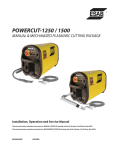
POWERCUT-1250 / 1500 MAINTENANCE TROUBLESHOOTING SCHEMATIC DIAGRAMS REPLACEMENT PARTS 449 450 section 4 maintenance 4.0 General If this equipment does not operate properly, stop work immediately and investigate the cause of the malfunction. Maintenance work must be performed by an experienced person, and electrical work by a trained electrician. Do not permit untrained persons to inspect, clean, or repair this equipment. Use only recommended replacement parts. Be sure that the wall disconnect switch or wall circuit breaker is open before attempting any inspection or work inside of the Powercut. 4.1Inspection and Cleaning Frequent inspection and cleaning of the PowerCut is recommended for safety and proper operation. Some suggestions for inspecting and cleaning are as follows: A. B. C. D. E. F. G. Check work cable for secured connection to workpiece. Check safety earth ground at workpiece and at power source chassis. Check heat shield on torch. It should be replaced if damaged. Check the torch electrode and cutting nozzle for wear on a daily basis. Remove spatter or replace if necessary. Make sure cable and hoses are not damaged or kinked. Make sure all plugs, fittings, and ground connections are tight. With all input power disconnected, and wearing proper eye and face protection, blow out the inside of the Powercut using low-pressure dry compressed air. Water or oil occasionally accumulates in compressed air lines. Be sure to direct the first blast of air away from the equipment to avoid damage to the Powercut. H. Occasionally, bleed all water from the filter beneath the air filter-regulator. 451 section 4 maintenance 4.2COMMON CUTTING PROBLEMS Listed below are common cutting problems followed by the probable cause of each. If problems are determined to be caused by the PowerCut, refer to the maintenance section of this manual. If the problem is not corrected after referring to the maintenance section, contact your ESAB distributor. A.Insufficient Penetration. 1. Current too low. 2. Cutting speed too fast. 3. Damaged cutting nozzle. 4. Improper air pressure. 5. Low air flow rate. B.Main Arc Extinguishes. 1. Cutting speed too slow. 2. Worn electrode. C.Dross Formation. (In some materials and thicknesses, it may be impossible to get dross-free cuts.) 1. Current too low. 2. Cutting speed too fast or too slow. 3. Improper air pressure. 4. Faulty nozzle or electrode. 5. Low air flow rate. D.Double Arcing. (Damaged Nozzle Orifice.) 1. Low air pressure. 2. Damaged cutting nozzle. 3. Loose cutting nozzle. 4. Heavy spatter accumulation on nozzle. E. Uneven Arc. 1. Damaged cutting nozzle or worn electrode. F. Unstable Cutting Conditions. 1. Incorrect cutting speed. 2. Loose cable or hose connections. 3. Electrode and/or cutting nozzle in poor condition. G.Main Arc Does Not Strike. 1. Worn electrode. 2. Loose connections. 3. Work cable not attached. H. Poor Consumable Life. 1. Improper gas pressure. 2. Contaminated air supply. 3. Low air flow rate. 452 section 4 maintenance 4.3IGBT KIT PC-1250/1500 handling and replacement p/n 0558008966 part number IGBT Handling 0558006151 38224 05S12020 05W01055 64302920 0558003084 qty DESCRIPTION 2 IGBT dual 150a 600v 1pcb igbt driver 4 screw skt hex m5 x 20 blk 4 washer flat m5 4 washer lock #10 1 compound heatsink aos - white Since IGBT gates are insulated from any other conducting region, care should be taken to prevent static build up, which could possibly damage gate oxides. All IGBT modules are shipped from the factory with conductive foam contacting the gate and emitter sense pins. Always ground parts touching gate pins during installation. In general, standard ESD precautions should be followed. Other handling precautions that should also be observed are as follows: • Use grounded work station with grounded floors and grounded wrist straps when handling devices. • Use a 100Ω resistor in series with the gate when performing curve tracer tests. • Never install devices into systems with power connected to the system. Module Replacement When mounting modules on a heatsink, certain precautions should be taken to prevent any damage against a sudden torque. If a sudden torque (“one-sided tightening”) is applied at only one mounting terminal the ceramic insulation plate or silicon chip inside the module may get damaged. The mounting screws are to be fastened in the order shown. Also, care must be taken to achieve maximum contact (i.e. minimum contact thermal resistance) for the best heat dissipation. A torque wrench should be used. Tighten mounting and terminal screws per Torque Requirements shown in illustration below. If device is over-torqued, the device can be damaged like the above “one-sided tightening”. Application of a Thermal Compound or Thermal Pad on the contact surface is required to properly remove heat from the device. It is recommended that a unit manufactured with a thermal pad use thermal compound for replacement. Thermal compound may always be used as a replacement for a pad. Never use both compound and a pad. Thoroughly remove any residual material from the mating surfaces. Use supplied Heat Sink Compound or equivalent. Apply a thin layer (.005” nominal) between mating surfaces. 36 in/lbs (4.1 newton meters) Two-Point Mounting Type Initial tightening Final tightening 36 in/lbs (4.1 newton meters) Screw Fastening Order and Torque 453 section 4 maintenance 454 section 5 troubleshooting 5.0Troubleshooting ELECTRIC SHOCK CAN KILL! Be sure that all primary power to the machine has been externally disconnected. Open the line (wall) disconnect switch or circuit breaker before attempting inspection or work inside of the power source. Check the problem against the symptoms in the following troubleshooting guide. The remedy may be quite simple. If the cause cannot be quickly located, shut off the input power, open up the unit, and perform a simple visual inspection of all the components and wiring. Check for secure terminal connections, loose or burned wiring or components, bulged or leaking capacitors, or any other sign of damage or discoloration. The cause of control malfunctions can be found by referring to the sequence of operations and electrical schematic diagram and checking the various components. A volt-ohmmeter will be necessary for some of these checks. Voltages in plasma cutting equipment are high enough to cause serious injury or possibly death. Be particularly careful around equipment when the covers are removed. NOTE: Before checking voltages in the circuit, disconnect the power from the high frequency PC Board (PCB-2, Connector J2) to avoid damaging your voltmeter. 455 section 5 troubleshooting 5.1Troubleshooting GUIDE A. Power Light does not come on. 1.Visually inspect the machine for any damage. 2. Check following: a. Check if the machine power cord is plugged into the input power receptacle. b. Measure the input power at the receptacle. If not present, then check the wall disconnect switch and it’s fuses. c. Check Fuse (F1). 3. If above items check OK , the problem is internal. Send unit to an Authorized Repair Station for repair. a. Ensure that ribbon cable is connected to main PCB-1 and front panel PCB-3 b. Measure voltage between pins P7-5 and P7-6 of the control board. If there is no voltage, then replace Control Transformer (T6). c. If the voltage is present, then the pilot light may be burnt out. B. No Air Flow 1. Check air inlet supply. Unit requires 350 cfh at 80psig (165.1 l/m @ 5.5 bars). 2. Check air hose and connections. Tighten if leaking. 3. Does air flow when “air test” switch is in test position? a. If not, check torch consumables, replace if necessary. b. If above items check OK , the problem is internal. Take unit to an Authorized Repair Station for repair. C.The Power light is on, but nothing happens when the torch switch is depressed. Fault light does not activate. NOTE: Unplug high frequency connection before attempting to work on this problem. 1. With the machine power on, depress the torch switch. On the control board the LED 1 should be lit as long as the switch is depressed. If not then check: a. Turn power off to the machine. Unplug Control board. Put an ohmmeter across J3-3 and J3-4 to take resistance reading. Depress torch switch. Meter should read a short. If not, then one of the following is not working properly: b. Torch switch or the leads. Unplug the torch switch leads at the machine. Put a meter across the two plug pins. Meter should read a short when the torch switch is depressed. If not, then either there are broken switch leads or a malfunctioning switch. 456 section 5 troubleshooting 2. Check transformer secondary voltages at the output diode modules. Refer to system schematic. Replace the transformer module if the correct secondary voltages are not present. 3. If everything above checks out all right, then the PCB1 Control Board should be replaced. D. Fault light activates when torch switch is closed. The machine monitors conditions necessary for the safe operation of the Powercut. The fault lights will glow under the following conditions and operations will come to a stop. 1. High/Low line voltage. The "AC LINE" light will blink to indicate that the input voltage is outside the +/- 15% range of the nominal voltage. 2. Gas Flow indicator - The fault light will blink to indicate that the air flow is low or that the torch is not providing any back pressure. a. Check the air pressure at the machine regulator. It should be adjusted to 80 psig (5.5 bars). If no air pressure, check the air at the supply point. Also, check for any obstructions in the air hose. b. Air flow may be blocked at the torch tip. Check the torch consumables (see Figure 3.4). Also check for any obstructions in the torch leads. NOTE: If above items check OK , the problem is internal. Send unit to an Authorized Repair Station for repair. c. Put the ‘Air Check’ switch to On position. Air should flow through torch. If not, and air pressure is set at required 80 psig (5.5 bars), check gas Solenoid (SOL1) for proper operation. d. Air Check switch may also be malfunctioning if the air is flowing continuously or putting in the On position does not turn air on. 3.Over Temperature indicator . The fault light will blink to indicate that the machine has overheated. This generally indicates that the air flow has been blocked. Clear blockage and allow the power source to cool before operating. a. Thermal Switch (TS1) may be open. It will open if the heat sink temperature reaches 80°C. With the machine power off, check the continuity between P6-7 and P6-8 of the control board. If the switch is OK, then the ohmmeter should read a direct short. If not, then it should read open. b. If the switch is malfunctioning, replace it. Clean the surface of the heat sink before installing the switch. 4. Fault Indicator. When this light blinks, either the system failed to initiate a pilot arc after a number of attempts, or there has been an over-current event within the system. a. If the light blinks for 10 seconds and then stops, then the problem is pilot arc initiation. Check the consumables in the torch. b. If the light continues to blink, and the system does not reset, then the fault is an over-current event. One likely source of an over-current fault is a nozzle to electrode short. Turn off the machine and inspect the torch and its consumables. Replace the consumables as needed. Turn the machine back on. If the problem occurs again, the machine may require service. 457 section 5 troubleshooting c. To check if the output is shorted, measure the resistance by putting the ohmmeter leads across the output. Put the black lead to the "work" terminal and the red lead to the torch electrode terminal. The reading should be about 2K OHMs. b. If the resistance reading is different than above, check the torch, the output bridge and Start-up Board (PCB-6). E.Air is On but nothing happens when torch switch is operated. 1. Check the torch. Make sure that the valve pin is installed and the heat shield is very tight. 2. Check to assure high frequency is present at the torch. Disconnect HI FREQUENCY leads. Check for 575 volt supply to the high frequency unit between P2A-1 & P2A-3 of the High Frequency Board (PCB2) with torch switch closed. 3. With HI FREQUENCY leads disconnected, measure open circuit voltage. It should be 320 VDC between “Work” and “Torch” terminals. If it is not present then any one of the following may not be working properly: a. Check the operation of the Thermal Switch (TS1). See D.3.a. above. b. Check Air Check switch operation. It might be stuck in On position. Pilot arc will not initiate if this switch is in the ON position. (safety reasons) c. Check air flow switch. There may be internal short. See D.2.c above. d. Measure voltage across C5 or C6 capacitor. It should be as follows: approx. 325 VDC with 230 V supplied to the 230/460 volt unit. approx. 294 VDC with 208 V supplied to the 230/460 volt unit. approx. 325 VDC with 460 V supplied to the 230/460 volt unit. approx. 282 VDC with 400 V supplied to the 400 volt unit. approx. 400 VDC with 575 V supplied to the 575 volt unit. If not, one of following could be malfunctioning: 1). Check the capacitors C5 and C6 for any damage. 2.) Check input bridge/SCR Module (BR1) This can be checked without taking it out of the circuit using an volt/ohmeter. Replace it if found malfunctioning. Follow bridge installation instructions. 3.) Check Inrush current resistor (R1), located on the Input Bridge Heatsink and SCR (Q1). Replace if malfunctioning. e. IGBTs may be damaged. See IGBT installation procedure. Before replacing IGBTs, make sure to check the zener diodes and pico fuses on the IGBT driver boards. 458 section 5 troubleshooting F. High Frequency and Pilot Arc are on but Main Arc does not transfer. 1. Make sure work clamp is connected to work material. 2. Check the torch. Replace consumables if necessary. G. Poor Cutting Performance. 1. Check air supply regulator . It should be adjusted to 80 psig (5.5 bars). 2. The air supplied to the torch should be free of oil and water. 3. Make sure the consumables in the torch are acceptable. 4. Check open circuit voltage. See E.3 above. 5. Check the output. Use a calibrated current probe capable of measuring 100 amps in the presence of high frequency. H. Air does not shut off. 1. Check air test, the gas solenoid valve is energized when the switch is in the “on” position. 2. Does air flow stop when the torch switch is unplugged? If yes, check and repair the torch. If not, send unit to an Authorized Repair Station for repair. a. Check voltage to solenoid coil, if present when torch switch is unplugged, replace PCB1. If voltage is “0”, replace solenoid valve. I.Main arc is difficult to start. 1. 2. 3. 4. 5. The most common reason is worn or missing consumables. Check and replace if necessary. Input air must be clean and dry. Input air pressure must be at least 85 psig (5.7 bars). Torch connections must be tight. Work cable and clamp must be in good condition and must make a good electrical connection to the material to be cut. 6. If above items check OK , the problem is internal. Send unit to an Authorized Repair Station for repair. a. Missing or weak pilot arc. Check pilot arc fuse, open circuit voltage and pilot arc wiring. b. Inoperative Start-up Board (PCB-6). 459 section 5 troubleshooting 5.2Reference Voltage Checks A.Control Board Assembly (PCB1) 1. LED’s LED- (D9) - LED- (D4) - LED- (D1) - Torch Switch Pilot Arc Relay Gas Solenoid Valve 2. Voltage Test Points Tests are made with power on - no arc. Disable High Frequency by disconnecting blue wire with black sleeve TP-1- Torch trigger signal TP-4- IGBT’s driving signal - switching frequency = 18.5 KHz TP-5- IGBT’s driving signal - switching frequency = 18.5 KHz TP-7- +5 vdc TP-8- +15 vdc TP-9- -15 vdc TP-10 - Ground 54 µs 13vdc 0 13vdc Figure 5.1 IGBT Gating Signal 460 section 5 5.3 troubleshooting Sequence of Operation A. TRIGGER LOCK “UNLOCK” position (Applies to PT-21AMX and PT-32EH Torches) TORCH SWITCH GAS SOLENOID VALVE PUSH RELEASE OPEN 2 SEC. PREFLOW 20 SEC Postflow FLOW SWITCH FAULT OVERLOAD LIGHT HF CIRCUIT CLOSE CLOSE OPEN ENERGIZE PILOT ARC INVERTER CUTTING ARC (CURRENT) NOTES: 1. When the torch switch is pushed during postflow period, the postflow and preflow times are canceled, and the HF is energized immediately. 2. When the red fault light comes on, cutting operation should be stopped. The postflow time starts from the moment the torch switch is released. 461 section 5 troubleshooting B. TRIGGER LOCK "LOCK" position (Manual Cutting Only with PT-32EH Torch) TORCH SWITCH PUSH RELEASE PUSH GAS SOLENOID VALVE OPEN RELEASE CLOSE PREFLOW 2 SEC. 20 SEC CLOSE FLOW SWITCH POSTFLOW Postflow OPEN FAULT LIGHT ENERGIZE HF CIRCUIT PILOT ARC INVERTER CUTTING ARC (CURRENT) NOTES: 1. When the torch switch is pushed during postflow period, the postflow time is reset, the preflow time is canceled, and the HF is energized immediately. 2. When the red fault light comes on, cutting operation should be stopped. The postflow time starts from the moment the torch switch is released. 3. FAULT light is on during second "turn-off" trigger only. This does not affect performance in any way. 462 section 5 troubleshooting NOTE: Schematics and Wiring Diagrams on 279.4mm x 431.8mm (11” x 17”) paper are included inside the back cover of this manual. 463 section 5 troubleshooting 464 section 5 troubleshooting 465 section 5 troubleshooting 466 section 6 replacement parts 6.0Replacement Parts 6.1 General Always provide the serial number of the unit on which the parts will be used. The serial number is stamped on the unit nameplate. 6.2Ordering To ensure proper operation, it is recommended that only genuine ESAB parts and products be used with this equipment. The use of non-ESAB parts may void your warranty. Replacement parts may be ordered from your ESAB Distributor. Be sure to indicate any special shipping instructions when ordering replacement parts. Refer to the Communications Guide located on the back page of this manual for a list of customer service phone numbers. Note Bill of material items that have blank part numbers are provided for customer information only. Hardware items should be available through local sources. 6.3IGBT KIT PC-1250/1500 replacement p/n 0558008966 part number 0558006151 38224 05S12020 05W01055 64302920 0558003084 qty DESCRIPTION 2 IGBT dual 150a 600v 1pcb igbt driver 4 screw skt hex m5 x 20 blk 4 washer flat m5 4 washer lock #10 1 compound heatsink aos - white 467 section 6 replacement parts 468 revision history 1. 2. 3. 4. Original release of this manual is 05/2003. Revision of 11/2003 changed panel views to show updated voltage switch. Revision of 04/2004 - Updated schematic diagram on page 66 per change notice 043018. Revision of 05/2004: In the Replacement Parts Section - changed bom item # 42 from: 38131 to: 0558038276. See DNECO # 043086. 5. Revision of 10/2004 - Updated schematics on Pages 65 and 67 per change notice 043236. 6. Revision of 12/2004: Schematics moved to 11 x 17 pages in back of manual. 7. Revision of 01/2005: Changed main transformer module from 0558003377 to 0558005313. (CN# 053002) 8. Revision - 06/2005 - added Air Line Filter Regulator p/n 0558005394 note in Replacement Parts section per CN #053013. 9. Revision 08/2005 - In replacement parts section, updated finger guard from: p/n 0558002994 to: p/n 0558005659 & cover torch connection from: p/n 0558002464M to: 0558005658 per CN-053103. 10. Revision 12/2005: Updated front & rear views. In replacement parts section p/n table #2, item 32, chgd p/n from: 951800 to: 0558005462. Removed Air Line Filter Regulator p/n 0558005394 note in Replacement Parts section. 11. Revision 01/2006: Changed p/n 0558003075 to p/n 0558001379 per DNECO #053179. 12. Revsion 03/2006: Added Estonian and Latvian languages per Alaaeldin Assal request. Added 0555001935F to the "Console" list in Subsection 1.2.1. Added 0558005902 and 0558005903 to the "Ordering Information" list in Subsection 1.2.2. Added 0558003517 and 0558005900 to the "Console" list in Subsection 1.2.2. Added 0558005331 and 0558005900 to the BOM charts in Section 6, Replacement Parts, refer to ECN #063042 and PA #6900-05-24 13. Revision 05/2006: Updated P/Ns in Replacement Parts Tables per ECN #063080. 14. Revision 12/2006: Changed Torch Holder Assy p/n from: 16V83 (0558004250) to: 0558005926 and updated picture. 15. Revision 07/2007: Changed content for "CE" spare parts kits (in manual cutting section) to include drag heat shield p/n 0558004206. 16. Revision 12/2007: Added 400V harmonics info to PC-1500 pages. Updated Replacement Parts Section. 17. Revision 03/2008: Updated Replacement Parts Section per ECN #083042. 18. Revision 04/2009: Updated replacement parts section per ECN #093066 and updated IGBT info. 469 ESAB subsidiaries and representative offices Europe AUSTRIA ESAB Ges.m.b.H Vienna--Liesing Tel: +43 1 888 25 11 Fax: +43 1 888 25 11 85 BELGIUM S.A. ESAB N.V. Brussels Tel: +32 2 745 11 00 Fax: +32 2 726 80 05 THE CZECH REPUBLIC ESAB VAMBERK s.r.o. Prague Tel: +420 2 819 40 885 Fax: +420 2 819 40 120 DENMARK Aktieselskabet ESAB Copenhagen--Valby Tel: +45 36 30 01 11 Fax: +45 36 30 40 03 FINLAND ESAB Oy Helsinki Tel: +358 9 547 761 Fax: +358 9 547 77 71 FRANCE ESAB France S.A. Cergy Pontoise Tel: +33 1 30 75 55 00 Fax: +33 1 30 75 55 24 GERMANY ESAB GmbH Solingen Tel: +49 212 298 0 Fax: +49 212 298 204 GREAT BRITAIN ESAB Group (UK) Ltd Waltham Cross Tel: +44 1992 76 85 15 Fax: +44 1992 71 58 03 ESAB Automation Ltd Andover Tel: +44 1264 33 22 33 Fax: +44 1264 33 20 74 HUNGARY ESAB Kft Budapest Tel: +36 1 20 44 182 Fax: +36 1 20 44 186 ITALY ESAB Saldatura S.p.A. Mesero (Mi) Tel: +39 02 97 96 81 Fax: +39 02 97 28 91 81 THE NETHERLANDS ESAB Nederland B.V. Utrecht Tel: +31 30 248 59 22 Fax: +31 30 248 52 60 NORWAY AS ESAB Larvik Tel: +47 33 12 10 00 Fax: +47 33 11 52 03 POLAND ESAB Sp.z.o.o Warszaw Tel: +48 22 813 99 63 Fax: +48 22 813 98 81 PORTUGAL ESAB Lda Lisbon Tel: +351 1 837 1527 Fax: +351 1 859 1277 SLOVAKIA ESAB Slovakia s.r.o. Bratislava Tel: +421 7 44 88 24 26 Fax: +421 7 44 88 87 41 SPAIN ESAB Ibérica S.A. Alcobendas (Madrid) Tel: +34 91 623 11 00 Fax: +34 91 661 51 83 SWEDEN ESAB Sverige AB Gothenburg Tel: +46 31 50 95 00 Fax: +46 31 50 92 22 ESAB International AB Gothenburg Tel: +46 31 50 90 00 Fax: +46 31 50 93 60 SWITZERLAND ESAB AG Dietikon Tel: +41 1 741 25 25 Fax: +41 1 740 30 55 North and South America ARGENTINA CONARCO Buenos Aires Tel: +54 11 4 753 4039 Fax: +54 11 4 753 6313 Asia/Pacific AUSTRALIA ESAB Australia Pty Ltd Ermington Tel: +61 2 9647 1232 Fax: +61 2 9748 1685 CHINA Shanghai ESAB A/P Shanghai Tel: +86 21 6539 7124 Fax: +86 21 6543 6622 INDIA ESAB India Ltd Calcutta Tel: +91 33 478 45 17 Fax: +91 33 468 18 80 INDONESIA P.T. Esabindo Pratama Jakarta Tel: +62 21 460 01 88 Fax: +62 21 461 29 29 MALAYSIA ESAB (Malaysia) Snd Bhd Selangor Tel: +60 3 703 36 15 Fax: +60 3 703 35 52 SINGAPORE ESAB Singapore Pte Ltd Singapore Tel: +65 861 43 22 Fax: +65 861 31 95 Representative offices BULGARIA ESAB Representative Office Sofia Tel/Fax: +359 2 974 42 88 EGYPT ESAB Egypt Dokki--Cairo Tel: +20 2 390 96 69 Fax: +20 2 393 32 13 ROMANIA ESAB Representative Office Bucharest Tel/Fax: +40 1 322 36 74 RUSSIA-- CIS ESAB Representative Office Moscow Tel: +7 095 937 98 20 Fax: +7 095 937 95 80 ESAB Representative Office St Petersburg Tel: +7 812 325 43 62 Fax: +7 812 325 66 85 Distributors For addresses and phone numbers to our distributors in other countries, please visit our home page www.esab.com ESAB Asia/Pacific Pte Ltd Singapore Tel: +65 861 74 42 Fax: +65 863 08 39 SOUTH KOREA ESAB SeAH Corporation Kyung--Nam Tel: +82 551 289 81 11 Fax: +82 551 289 88 63 UNITED ARAB EMIRATES ESAB Middle East Dubai Tel: +971 4 338 88 29 Fax: +971 4 338 87 29 BRAZIL ESAB S.A. Contagem--MG Tel: +55 31 333 43 33 Fax: +55 31 361 31 51 CANADA ESAB Group Canada Inc. Missisauga, Ontario Tel: +1 905 670 02 20 Fax: +1 905 670 48 79 MEXICO ESAB Mexico S.A. Monterrey Tel: +52 8 350 5959 Fax: +52 8 350 7554 USA ESAB Welding & Cutting Products Florence, SC Tel: +1 843 669 44 11 Fax: +1 843 664 44 58 ESAB AB SE-- 695 81 LAXÅ SWEDEN Phone +46 584 81 000 Fax +46 584 123 08 www.esab.com 0558004232 04/2009