1
Owner's manual & Installation manual
Mode d'emploi et manuel d'installation
Manual de usario e instalaci6n
eMS 1
MARINE MECHANISM-LESS SOURCE UNIT
UNITE DE SOURCE MARINE SANS MECANISME
UNlOAD FUENTE MARINA SIN MECANISMO
(~-<'-~'~-CLARION-;RODUCT REGiSTiiAilONlNi=oRMATioN-~"'-'--\)
i
I
I
I
I
I;
For USA an~ Canada only
I
www.clarlon.com
Dear Customer:
Congratulations on your purchase of a Clarion mobile electronic product. We are
confident that you'll enjoy your Clarion experience.
!
There are many benefits to registering your product. We invite you to visit our website at
www.clarion.com to register your Clarion product.
I'
I!.'
,
We have made product registration simple with our easy to use website. The registration
form is short and easy to complete. Once you're registered, we can keep you informed of
important product information.
, Register at www.clarion.com - it's easy to keep your Clarion product up to date.
~_
• • I!I
.
_DIna·.,.
__
_
~
J
Contents
1. FEATURES .....•........................................................................................................... 3
2. PRECAUTIONS .......•...............................•.................................................................. 3
3. CAUTIONS ON HANDLING
3
4. CONTROLS..............................................•.................................................................. 4
About the Registered Marks, etc
4
Name of Buttons and Their Functions
5
6
5. OPERATIONS
Radio (AM/FM) Operation
7
Weather Band Operation
7
Sirius Radio Operation
8
iPod Mode Operation
9
USB Mode Operation
9
6. TROUBLESHOOTING
10
7. SPECIFICATIONS ...•.............•..•..............•......................................................•........... 11
INSTALLATION AND WIRE CONNECTION MANUAL
12
2
CMS1
1. FEATURES
• Rear USB Connector
• 40W x 4 Built-In Amplifier
• Compatible with iPod®
• Sirius Radio Ready
• Weather Band Radio
• Watertight & Corrosion Proof
•
_ . _Pla.:Y5 _--1
D
'. . Windows
.'M Media'M
@J
Madefor
iPod
,",.3 usn
SIRIUS"
READYe3t ID3TAG
2. PRECAUTIONS
A
WARNING
• For your safety, while boating, keep the volume to a level at which external
sounds can be heard.
1. This unit has precision parts inside. Even
in the event that trouble arises, never open
the case, disassemble the unit, or lubricate
the parts.
2. This equipment has been tested and found to
comply with the limits for a Class B digital
device, pursuant to Part 15 of the FCC Rules.
These limits are designed to provide
reasonable protection against harmful
interference in a residential installation. This
equipment generates, uses, and can radiate
radio frequency energy and, if not installed
and used in accordance with the instructions,
may cause harmful interference to radio
communications. However, there is no
guarantee that interference will not occur in a
particular installation. If this equipment does
cause harmful interference to radio or
television reception, which can be determined
by turning the equipment off and on, the user
is encouraged to consult the dealer or an
experienced radiolTV technician for help.
INFORMATION FOR USERS:
CHANGES OR MODIFICATIONS TO THIS
PRODUCT NOT APPROVED BY THE
MANUFACTURER WILL VOID THE
WARRANTY AND WILL VIOLATE FCC
APPROVAL.
( E=MO=OEL'----=C:.:..M5=-=-I_---=cla=rIOfl=
USA: AMS30-1710kHz. FM 87.9-107.9MHz
12ve GROUND EUROPE: AM522·1620kHz, FM87.S.10B.OMHz
This product includes technology owned by Microsoft Corporation and cannot
be used or distributed without a license from MSLGP.
This device complies wnh Pafl 15 of Ihe FCC rules. Ope/ahan IS subject to the
following two condiTiOns: (1) this device may not cause harmful interference, and
(2)lhis device must accepl any Interference received.Ii'lCILJOinglntertefencethal
may cause undesired operation.
THIS PRODUCTION COMPLIES WITH DHHS RULES 21 CFR SUBCHAPTER J
APPLICABLE AT DATE OF MANUFACTURE
CLARION CORPORATION OF AMERICA
6200 GATEWAY DRIVE, CYPRESS. CALIFORNIA 90630. USA
MANUFACTURED:
I' - - - - - - - - - - - - - - - - '
MANUFACTURER:
SMX
SERIAL NO.
MADE IN CHINA
• Protect product from water. Do not submerge or expose the product directly to
water, as this can cause electrical shorts, fire or other damages.
• Protect from high temperature. Expose to direct sunlight for an extended period of
time can produce very high temperature in your vessel. Cool down the interior
before starting the playback.
CMS1
3
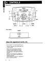
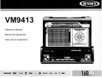
4. CONTROLS
Source Unit
Clarion
Ft 1 ICI8.CII]
l
[<!)]
£CMP3:::J-"IPODUSB@l~(ARTISTltL
8EI3~
~cwMA:::J7IsAT~(ALBUMIITITLEI I\CH!'f
SRC
~/II ]
[ ENTER
[MUTE]
[ADJ]
lOP]
Tuner Module
RESET
I
[000)
(r
RESET
About the registered marks, etc.
• Windows Media™ and the Windows® logo are
trademarks, or registered trademarks of
Microsoft Corporation in the United States and/
or other countries.
• "Made for iPod" means that an electronic
accessory has been designed to connect
specifically to iPod and has been certified
by the developer to meet Apple performance
standards.
Apple is not responsible for the operation of
this device or its compliance with safety and
regulatory standards.
iPod is a trademark of Apple Inc., registered in
the U.S. and other countries.
4
CMS1
[DISP]
Name of Buttons and their Functions
Note:
Be sure to read this chapter while referring
to the front diagram in chapter "4. CONTROLS"
SOURCE UNIT
[<!>] Power Button
• Press the button to turn power on or off.
[voL] [V9 L ] Volume Button
• Press VOL+ button to increase the volume.
• Press VOL- button to decrease the volume.
The maximum volume level is "46".
[MUTE] Button
• Press this button to mute the audio output.
• Press it again to restore the audio output.
[SRC] Source Button
• Press SRC button to switch modes among FM,
AM, Weather Band, Sirius, USB, iPod and
AUX In (Optional Auxiliary Input).
[ADJ] Adjust Button
• Press ADJ to access the adjust menu.
Bass Level
Use the VOLUME buttons to adjust the Bass
level range from "-6" to "+6".
Default setting is "0".
Treble Level
Use the VOLUME buttons to adjust the Treble
level range from "-6" to "+6".
Default setting is "0".
Balance
Use the VOLUME buttons to adjust the Balance
between the left and right speakers from
"L12" (full left) to R12 (full right).
Default setting is COO.
Fader
Use the VOLUME buttons to adjust the Fader
between the rear and front speakers from
"R12" (full rear) to F12 (full front).
Default setting is COO.
Loud
Use the VOLUME buttons to select Loudness
between ON and OFF. Default setting is OFF.
Contrast
Use the VOLUME buttons to see LCD contrast
from 01-08. Default setting is 03.
Beep
Use the VOLUME buttons to select Beep tone
between ON and OFF. Default setting is ON
Reset yes
Press ENTER button to return the EEPROM to
factory default set up values.
[DISP] Display Button
• Press this button to switch the display
indication.
• Press and hold the button to scroll display.
[OP] Option Button
• Press option button to access option
menu items for necessary functions in
every mode.
• In different modes, the option menu items
are different. Please see the operation
introduction of every mode for more details.
[~~~~] Play/Pause/Enter Button
• Press this button for 2 seconds to Play
or Pause.
• Press this button to confirm operations
in Tuner Mode, Weather Band Mode,
Sirius Radio mode, iPod mode and
USB mode.
[~] [~]
Tuning Down, Tuning Up Buttons
• Use these buttons for tuning up and down
in Tuner Mode, Weather Band Mode,
Sirius Radio mode, iPod mode and
USB mode.
[...] [...] Search Up, Search Down Buttons
• Use these buttons for search up and down
in Tuner Mode, Weather Band Mode,
Sirius Radio mode, iPod mode and
USB mode.
TUNER MODULE
[RESET] Button
• Press RESET button with a ball point
pin to:
1. Initiate installation after all wiring is
completed.
2. Function buttons do not operate.
3. Error symbol on display.
CMS1
5
·
5. OPERATIONS
.
.
Basic Operations
Note:
• Be sure to read this chapter referring to the chapter
"4. CONTROLS".
ACAUTION
When the unit is turned on, starting and
stopping the engine with its volume raised to
the maximum level may harm your hearings.
Be careful about adjusting the volume.
Turning on and off the power
Note:
• Start the engine before using this unit.
• Be careful about using this unit for a long time
without running the engine. If you drain the vessel
battery too far, you may not be able to start the
engine and this can reduce the service life of the
battery.
1. Start the engine. The power button / knob
illumination on the unit will light up.
~
EngineON
~ position
2. Press the [<!>] power button to turn On or
Off the power.
Selecting a mode
1. Press [SRC] button to display source
menu.
* External equipment not connected to this unit
is not displayed.
2. Press the [ENTER] button to select desired
mode.
Adjusting the volume
1. Press VOL+ button to increase the volume.
2. Press VOL- button to decrease the volume.
ACAUTION
While boating, keep the volume level at
which external sound can be heard.
6
CMS1
Mute
Press the [MUTE] button to turn the mute On
and Off.
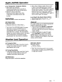
Radio (AM/FM) Operation
[.] [~] Tuning Down, Tuning Up Buttons
1. Auto Seek tuning Up/Down:
Press this button less than 2 seconds to
automatically seek the next strong section.
2. Manual Tuning Up and Down:
Press and hold this button more than
2 seconds to seek stations down step
by step.
[ENTER] Button
Press this button to confirm the operation.
[OP] Option Button
Radio Mode Options:
CNormal~Auto Store-Manu Store J
1. Auto Store: Press OPTION button to access
Auto Store, then press ENTER button to
automatically select six strong stations and
store them into six presets. The new stations
replace any stations already stored in the band.
The unit will pause for 5 seconds at each
preset station after Auto Store is completed.
2. Manu Store: Select a station that you want
to store. Press OPTION button to access
Manual Store. Press ENTER button to go into
manual store interface. The preset number is
flashing. Press up or down key to select a
preset number. Press ENTER button again to
store current station into preset.
[.] [...] Search Up, Search Down Buttons
1. Recall Preset Down: P6-P5-P4- .... P1
2. Recall Preset Up: P1-P2-.... P5-P6
Area set
This option allows you to select the appropriate
frequency spacing for your area.
1. Press and hold the [MUTE] and [ADJUST]
buttons at the same time for more than 2
seconds to get into the world tuner frequency
/region setting.
2. Use [.] or [~] button to select the region.
Press [ENTER] to confirm the selection.
NOTE: Default is USA frequency. Once the
region is changed, all the stations in the preset
memory will be erased.
Weather Band Operation
[~ ]
Tuning Up Button
1. Press and hold this button more than 2 sec's,
to seek the available among all 7 weather
. band stations step by step.
[.] Tuning Down Button
1. Press and hold this button more than 2 sec's,
to seek the available stations among all 7
weather band stations step by step.
[OP] Option Button
WB Mode options:
Normal~ Scan 1
r
1. Scan: the unit will pause for 5 sec's at each
strong station circularly, press ENTER button
to stop scan function.
[ENTER] Button
Press this button to confirm the operation.
CMS1
7
Sirius Radio Operation
Channel Up
[~]
IDown [<il] Operation
1. Channel Up/Down tuning:
Press this button less than 2 seconds to
search for a channel.
2. Fast Search Channel Up and Down:
Press and hold this button more than
2 seconds to fast search.
[ENTER] Button
Press this button to confirm the operation.
Category Tuning Up [ .... ] and Down [T ]
Category tuning:
1. Press Up or Down to access Category
search. LCD will display "Category" for
1 second, then display category name.
2. While in the Category, press Up or
Down button to view category name.
3. Press ENTER or press Right button to
choose desired channel in that category.
4. Press Up or Down button to select a
channel within chosen category.
5. Press ENTER to confirm channel selection.
Note: When selecting channel, press Left [<il J
to return to last selected category.
lOP] Option Button
Sirius Mode Options:
rNormal-+Call Preset -+ Manu Store]
1. Call Preset: Press OPTION button to access
Recall Presets and then press ENTER button
into Recall Preset mode. Press Up/Down
button to choose preset among P1-P18.
Press ENTER button to exit Recall Preset
mode or it will automatically exit Recall Preset
mode after 10 seconds if there is no operation.
2. Manu store: Select a channel which you
want to store, then press OPTION button to
access Manual Store. Press ENTER button
to go into manual store interface, the preset
number is flashing. Press Up or Down button
to select a preset number. Press ENTER
button again to store current channel into
preset.
8
CMS1
[DISP] Display button
Press this button to check the channel info
like Artist name, song title, category, channel
name.
Note: This unit doesn't support Skip/Lock
function. If a channel is locked/skipped in
the Sirius Tuner, then connected to this
unit, the channels will remain locked/
skipped.
To unlock or unskip the channels, you need
to put the Sirius Tuner back into another
dock that is available for unlocking or
unskipping channels.
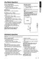
iPod Mode Operation
[~] Up / [<il] Down Buttons
1. Press this button less than 2 seconds 'to
play next/previous track.
2. Press and hold this button more than
2 seconds to fast forward/backward the song.
lOP] Option Button
iPod Mode Options:
Normal-+Repeat Song-+ Random AII-+
_ -. Random Folder ~
C
[DISP] Display button
[ENTER] Button
Press this button to check iPod information.
Press this button to confirm the operation.
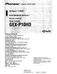
Note:
This unit does not support iPod direct
connection to USB port.
The iPod must be connected to tuner
module (white color) thru 8-pin Din
extension cable.
iPod Search [ ... ] Up /
[~]
Down
1. Press Up/Down button to enter iPod search
mode.
2. Press Up/Down button to select
among Play lists-+Artists-+Albums-+Genres-+
Songs-+Composers.
3. Press ENTER key or RIGHT button to confirm
selecting Play lists or Artists or Albums or Genres
or Songs or Composers.
4. When LCD display the desired Play list or Artist
or Album or Genre or Composer, press ENTER,
then the Music file will be displayed on LCD.
5. Press Up/Down button to select File.
6. Press ENTER key to confirm wanted File.
7. Play the file.
Note: When selecting file, press Left
button to return last layer (Album).
0
0
~!1W_
0
0
iPod
UJ
l-
DEl
@
~
@
'--'"
x',
I
a-pin DIN
Connector
~
USB Mode Operation
NOTE: CMS1 does not support removable hard drive.
[~]
Up / [<il] Down Buttons
1. Press this button less than 2 seconds to
play next/previous track.
2. Press and hold this button more than
2 seconds to fast forward/backward the song.
4. Display file (Song)
5. Press [... ] Up/ [~] Down button to select
File.
6. Press ENTER key to confirm wanted File
7. Play the File.
[ENTER] Button
Note: When selecting file, press Left
button to return last layer (Folder).
When under normal playing status, it works as
Play/Pause function. When entering into ADJ
menu or OPTION menu it works as Enter function.
Navigate Search [ ...] Up / [ ~] Down
1. Press Up/Down button to enter Navigate
mode. LCD will display "Navigate" for 1 second.
Then it will display the Folder or File name.
2. Press Up/Down button to select Folder.
3. Press ENTER key to confirm wanted Folder,
or press Right [ ~ ] button to go directly to wanted
Folder.
[OP] Option Button
USB Mode Options:
Normal-+ Repeat Song -+ Repeat
Folder-+lntro AII-+ Intro Folder-+
Random AII-+ Random Folder
1. Press OP button to access Option menu.
2. Press OP button to select the Option items.
3. Press ENTER button to proceed the
selected Option item.
[DISP] Display button
Check MP3 information.
CMS1
9
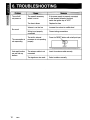
6. TROUBLESHOOTING
The vessel's accessory
switch is not on
If the power supply is properly connected
to the vessel's accessory terminal,
switch the ignition key to "ACC"
The fuse is blown
Replace the fuse
Volume is set too low
Increase the volume to audible level
Wiring is not properly
connected
Correct wiring connections
The built-in internal
processor is not operating
properly
Press the RESET button with a ball point pen
No sound
The commander is
not responding
RESET
Auto seek function
can not find any
stations
10
CMS1
The antenna cable is not
connected
Insert the antenna cable securely
The signals are too weak
Select a station manually
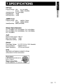
7. SPECIFICATIONS
FMTuner
Frequency Range: USA
87.9-107.9MHz
Europe FM87.5-108.0MHz
Usable Sensitivity: 4~V (S/N=30dB)
Image Rejection:
>45dB
Stereo Separation: >25dB
AMIMWTuner
Frequency Range: USA
AM530-1710kHz
Europe AM522-1620kHz
Usable Sensitivity: 36dB (S/N=20dB)
Weather Band Selection
CH.1 162.400MHz CH.2 162.425MHz CH.3 162.450MHz
CH.4 162.475MHz CH.5 162.500MHz CH.6 162.525MHz
CH.7162.550MHz
Audio
Maximum Power Output: 40W x 4
Bass Control (100Hz):
±10dB
Treble Control (10kHz): ±10dB
General
Power Supply Voltage:
Grounding System:
Speaker Impedance:
14.4V DC (10.8 to 15.6V allowable)
Negative Ground
4-8 ohms per channel
NOTE:
Specifications and design are subject to change
without notice for further improvement.
Power Output:
16W RMS x 4 Channels at 40
and 1% THD+N
Signal to Noise Ratio:
74 dBA (reference: 1 W into 4 0)
CMS1
11
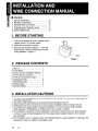
• Contents
1. BEFORE STARTING
2. PACKAGE CONTENTS
3. INSTALLATION CAUTIONS
4. MAIN UNIT INSTALLATION
5. TUNER MODULE INSTALLATION
6. WIRE CONNECTION
12
12
12
13
14
15
1. BEFORE STARTING
1. This set is exclusively for use in vessels with a
negative ground 12 V power supply.
2. Read these instructions carefully.
3. Be sure to disconnect the battery" - " terminal
before starting. This is to prevent short circuits
during installation. (Figure 1)
Battery
Figure 1
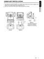
2. PACKAGE CONTENTS
1. Main Unit
1
2. Tuner Module
1
3. Owner' manual & Installation Manual .. 1
4. 12-Pin Molex fm connector
1
5. 8-Pin DIN 10' Extension Cable
1
6. Tapping Screw M4
8
7. Machine Screw M4
2
8. Rubber Stopper
4
9. Mounting Bracket..
1
3. INSTALLATION CAUTIONS
1. In order to avoid any interference, do not install the tuner module or control unit in the proximity of
the engine compartment.
2. The use of unauthorized parts can cause permanent damage to the unit.
3. Always check your wire connections to ensure proper installation before turning on the unit.
4. Consult with your nearest dealer for proper installation or if common parts need to be used.
Seek assistance if modifications or drilling holes to your vessel is needed.
5. Do not install the unit where it will be subjected to excessive moisture, dust, dirt, foreign particles
or vibration. Areas of high temperature from the engine, direct sunlight, heater or hot air should
also be avoided.
6. Do not install the unit in a location where it will interfere with the vessel operation, or it will injure the
passengers if there is a sudden or emergency stop.
12
CMS1
4. MAIN UNIT INSTALLA TION
1. The control unit should be mounted to a dry, clean and flat surface. Ensure the rear gasket is fully
sealed to the mounting surface without distorting the unit.
2. Select one of the three recommended methods that best fit your vessel.
I
I
oo~o
o~o
t:
M4 Tapp;n9:j
Screw
4 Pes
Mounting
Bracket
Method 3
This method requires the
purchase of the optional
Gimbal mount accessory.
o
0'-------'0
Method 1
Method 2
CMS1
13
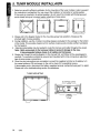
5. TUNER MODULE INSTALLAION
1. Select an area with sufficient ventilation for the mounting of the tuner module in order to prevent
the module from overheating. You may mount the module in a horizontal or vertical position.
If the module is mounted in a vertical position, do not mount the module with the harness exit
points directly facing up to prevent water collecting in these areas.
0
0
0
J
)
I
0
0
I
~
0
0
0
0
0
~
~
0
0
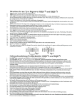
2. Please refer to the diagram below for the mounting screw hole positions. Always use the
shortest len!:')th of screw possible.
3. During installation, use the 4 rubber mounting stoppers (included in the package) for the bottom
of the module. This provides clearance from surface moisture and provides sufficient ventilation
for the heat sink.
4. Extension wires/cables may be needed to route the harness and cable throughout the vessel.
Note: Retain some slack in the harness! cables to prevent damage to the wires.
It is recommended relieve stress in all cables and harnesses.
5. Always read through the wiring diagram in this manual first, and follow all the wiring diagrams
carefully. The connections should be secured and insulated with crimp connectors or electrical
tape to ensure proper connections.
6. Once the wiring connections are completed, connect the negative terminal on the battery, turn
the vessel accessory ON and power on the unit to check if it is operating correctly.
If abnormalities occur, disconnect the battery negative terminal, recheck all wiring and try again.
Please refer to the troubleshooting section for assistance.
TUNER MOUNTING
•
•
•
•
M4 TAPPING SCREW
SCREW HOLE
Dgf~-~ll
RUBBER STOPPER
4PCS
14
CMS1
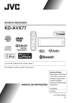
6. WIRE CONNECTION
'i=:::==:::::l~t:==r~~
RESET BUTTON
TUNER MODULE
o
o
o
o
ANTENNA
ORIENTATION
~¥
10 ~ +~ 01
~1
lJl
3 2 1
6 5 4
9 8 7
1 0
i;j1;a
SECTION A-A
PIN NO.
WIRE COLOR
jo
B!
~
12·Pin Molex Connector
Wire Code
SECTION B-B
WIRE DEFINITION
AWG
GREEN
SPEAKER REAR LEFT (+)
20
GREEN/BLACK
SPEAKER REAR LEFT (-)
20
RED
ACC(+'2V)
16
WHITE
SPEAKER FRONT LEFT (+)
20
WHITE/BLACK
SPEAKER FRONT LEFT H
20
ORANGElWHITE
ILLUMINATION
20
GREY
SPEAKER FRONT RIGHT (+)
20
e
GREYIBLACK
SPEAKER FRONT RIGHT (-)
20
9
BLUElWHITE
REMOTE(+)
20
10
PURPLE
SPEAKER REAR RIGHT (+)
11
PURPLEIBLACK
SPEAKER REAR RIGHT
12
BLACK
GROUND(-)
H
RI '~K
.RFD
P
.GREENIBLACK
PIIRPI F
r;RFFN
RIIlF/WHIT
G
CK
GRAY
lwi:trrE.
-A~3048mm('D')~
20
20
ool--~~
16
MALE
FEMALE
8 DIN CABLE
MALE
CMS1
15
Clarion Corporation of America
05/2009
All Rights Reserved. Copyright © 2009: Clarion Corporation of America
Printed in China / Imprime au Chine / Impreso en China
CMS1