1
SITE TECHNICAL DOCUMENTATION
myC2-3
Doc. No. : MTB DTS 8
Version : B
Date : February 21 2006
Produced by SAGEM COMMUNICATION GROUPE SAFRAN
ZI NORD Chemin de Baillot, BP 357, 82003 Montauban cedex, France
Tel (33) 5 63 21 21 21 - Fax (33) 5 63 21 21 54
Copyright 2006
SAGEM
Montauban, France
Contents
REF MTB DTS 8- Indice B - February 21 2006
Page 1
Site technical documentation myC2-3
Contents
REF MTB DTS 8- Indice B - February 21 2006
Page 2
Site technical documentation myC2-3
CONFIDENTIALITY
This document is SAGEM's limited company property. It can not be reproduced or communicated without the
written license.
Contents
REF MTB DTS 8- Indice B - February 21 2006
Page 3
Site technical documentation myC2-3
Contents
CHAPTER 1 - FOREWORD
1-1 HOW TO USE THE SITE TECHNICAL DOCUMENTATION
1-1-1 Use
1-2 ABREVIATIONS
1-3 COMMENTS SHEET
CHAPTER 2 - DESCRIPTION - OPERATION
2-1 REMINDERS ABOUT THE GENERAL CHARACTERISTICS OF GSM AND PCS NETWORKS
2-2 REMINDERS ABOUT THE HAND SET CHARACTERISTICS
2-3 IN & OUT CONNECTOR
2-3-1 Connector description
2-3-2 Signal description
2-4 IDENTIFICATION
2-4-1 Illustration
2-4-2 Description
2-4-3 Description after reparation
2-5 PHONE BLOCK DIAGRAMS
2-5-1 Block diagram
2-5-2 Standards and environment
2-6 EQUIPMENTS
2-6-1 Battery packs
2-6-1-1 Charactéristics
2-6-1-2 Description
2-6-1-3 Charging time
2-6-2 Mains modules
2-6-2-1 Description
2-6-2-2 Travel mains modules
2-6-2-3 Simple mains modules
CHAPTER 3 - SYMPTOMS
3-1 GENERAL
3-2 LIST OF REPORTED DEFECTS
3-3 ERROR MESSAGES DURING START UP
3-4 OTHER ERROR MESSAGES
3-5 LIST OF OBSERVED DEFECTS
3-6 INFORMATION ABOUT NEW NOTICED FAULTS
SYMPTOM SHEETS
CHAPTER 4 - TESTS AND CHECKS
4-1 GENERAL ABOUT TESTS
4-2 TEST TOOLS
4-3 INSTALLING ON A WORKSTATION (SMT STATION)
4-3-1 Minimum required configuration
4-3-2 Installing the cra downloading kit
4-3-3 Smt functions
Contents
REF MTB DTS 8- Indice B - February 21 2006
Page 4
Site technical documentation myC2-3
TEST SHEETS
CHAPTER 5 - MAINTENANCE PROCEDURES
5-1 TECHNICAL WORK LEVELS
5-2 SHORT LOOP PROCESS
5-3 MAINTENANCE TOOLS
PROCEDURE SHEETS
CHAPTER 6 - ACCESSORIES
6-1 PEDESTRIAN HANDSFREE KIT
6-1-1 Description
6-1-2 Charactéristics
CHAPTER 7 - TECHNICAL INFORMATION BULLETIN
7-1 PURPOSE
7-2 APPLICATION
CHAPTER 8 - ILLUSTRATED PARTS CATALOG
8-1 SPARE PARTS
APPENDIX
Appendix1
INDEX
Contents
REF MTB DTS 8- Indice B - February 21 2006
Page 5
Site technical documentation myC2-3
CHAPTER 1 - FOREWORD
This document is common to all myC2-3 phones in the SAGEM. It is composed of independent
sheets:
-Symptom sheets = Symp Sheet XX
-Test and check sheet= Test Sheet XX
-Maintenance procedure sheet= Proc Sheet X XX
The applicability of a procedure is indicated in the independent sheets title block.
These sheets are updated from time to time in Technical Information Bulletins (TIB).
The information contained in this document is non-contractual, since phone characteristics can
change.
Phones are managed based on SAGEM handset codes; any order for spare parts must refer to
these codes (typical code 25 xxx xxx-x).
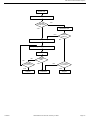
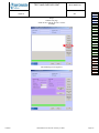
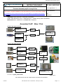
1.1 HOW TO USE THE SITE TECHNICAL DOCUMENTATION
This is a modular document. Each sheet is single and independent. In some cases several sheets
may have to be used in order to determine the complete procedure to be applied.
A troubleshooting chapter (chapter 3) is provided and is sorted according to the type of reported
fault, to determine the maintenance procedure to be carried out.
These sheets describe the procedure to be followed. They refer to test sheets or removal and
replacement maintenance sheets. Maintenance ,executed by the repair center, terminates either by
returning the product to the customer, or by dispatching it to level 3 maintenance (return to factory).
The procedure sheets have a number but not systematically consecutive but always in a growing
order.
Customers
Symptoms
level 3
Symp Sheet (Chap. 3)
Tests
Test Sheet (Chap. 4)
Maintenance
Proc Sheet (Chap. 5)
level 0-1-2
Checks
Test Sheet (Chap. 4)
Return to SAGEM
All sheets include illustrations to make it easier to read the procedure.
Chapter 1: Foreword, describes general data about this document.
Contents
REF MTB DTS 8- Indice B - February 21 2006
Page 1-1
Site technical documentation myC2-3
Chapter 2: Description - Operation, describes general data and options available in the myC2-3.
Chapter 3: Symptoms, contains troubleshooting procedures to be carried out on equipment.
Chapter 4: Tests and checks, contains tests and check procedures to be performed on the
equipment.
Chapter 5: Maintenance procedures, contains level 0 to 2 maintenance procedures to be carried out
on the equipment, and the procedure to return to SAGEM level 3.
Chapter 6: Accessories, describes the characteristics of accessories for myC2-3 phones.
Chapter 7: Technical Information Bulletins, contains the various modifications made to this
documentation.
Chapter 8: Illustrated Parts Catalogue, contains the various reference for spare parts.
1.1.1 Use
The DTS can be used by means of computer or by paper medium
-For circulation on the DTS one can use the contents which consists of bonds hypertext, and in
bottom of each page, one finds a bond which makes it possible to return until the contents.
-For the paper use an index east provides on last page which indicates the numbers of pages of
each heading.
1.2 ABREVIATIONS
AAC
Advanced Audio Codeur
ADPCM Adaptive Differential Pulse Codec Modulation
ALS
Alternative Line Services
AOC
Advice Of Charge
CCD
Charged Coupled Device
CLI
Calling Line Identification
CLIP
Calling Line Identification Presentation
CSTN
Colored Super Twisted Nematic
DCS
Digital Cellular System
EFR
Enhanced Full Rate
EMS
Enhanced Message Service
FDN
Fixe dial number
GPRS
General Packet Radio Service
GSM
Global System for Mobile
IMEI
Internationnal Mobile Equipment Identity
ISO
International Standard Organisation
LCD
Liquid Crystal Display
LU
Livret d'Utilisation
MMS
Multimedia Message Service
PCS
Personnal Communication Service
PIN
Personal Identity Number
Contents
REF MTB DTS 8- Indice B - February 21 2006
Page 1-2
Site technical documentation myC2-3
PUK
PIN Unlocking key
RF
Radio Frequence
SAR
Specific Absortion Rate
SIM
Subscriber Identity Module
SMS
Short Message Service
SMS CB Short Message Service Cell Broadcast
SMT
Sagem Mobile Tools
TFT
Thin Film Transistor
USSD
Unstructured Supplementary Service Data
VGA
Video Graphics Array
WAP
Wireless Application Protocol
WiFi
Wireless Fidelity
WSP
Wireless Session Protocol
1.3COMMENTS SHEET
Broad experience is very beneficial in several respects. Please let us know your comments so that
we can improve the contents and presentation of this document.
Your suggestions will be read carefully by :
-the design laboratory,
-production,
-the purchasing department,
-the after sales service,
-all users of this document.
All your suggestions are valuable, they will help us to better satisfy you.
Please photocopy and fill in the sheet 1-4.
Contents
REF MTB DTS 8- Indice B - February 21 2006
Page 1-3
Site technical documentation myC2-3
Document title:6LWH7HFKQLFDO'RFXPHQW
Reference :
Date :
Please fill in the following table :
([FHOOHQW
*RRG
)DLUO\JRRG
3DVVDEOH
Easy to find the required information
Clarity of information provided
Quality and accuracy of information given
Document outline
Document presentation and appearance
Quality of illustrations
General satisfaction
Do you think this document could be improved ? if so, how ? :
Improve the overall view
Improve the table of contents
Improve the structure
Add illustrations
Add details
Add information
Comments : __________________________________________________________________
____________________________________________________________________________
_____________________________________________________________
Would you like to discuss the problems mentioned in this questionnaire? If so, state :
Name of the person
: ________________
to
be
contacted
: ________________________
Phone
Company
: _____________________________________________
: _________________
Date
Address : ________________________________________________________________
7+$1.<28)253$57,&,3$7,1*,17+,6(148,5<<285&200(176:,//+(/386
&217,18(72,03529(7+(48$/,7<2)285'2&80(17$7,21$1'7+86%(77(5
6$7,6)<<2851(('6
When you have filled in this questionnaire, please send it :
-
by mail, to
6$*(06$
&+(0,1'(%$,//27%3
0217$8%$1&('(;
)5$1&(
<28&$1&217$&78621FUDPRELOH#VDJHPFRP
Contents
REF MTB DTS 8- Indice B - February 21 2006
Page 1-4
Site technical documentation myC2-3
CHAPTER 2 - DESCRIPTION - OPERATION
2.1 REMINDERS ABOUT THE GENERAL CHARACTERISTICS OF GSM 900, DCS 1800 and PCS
1900
Table 1 below gives the characteristics of the radio interface for the GSM 900, DCS 1800 and
PCS 1900 systems :
Frequency Band (MHz)
*60
'&6
880 - 915
925 - 960
1710 - 1785
1805 - 1880
Number of time intervals per TDMA
frame
8
Width 2 x W simplex (MHz)
Duplex spacing (MHz)
2 x 25
2 x 75
45
95
Modulation speed (kbit/s)
271
Speech throughput (kbit/s)
13 (5,6)
Maximum data throughput (kbit/s)
12
Multiple access
Multiplexage fréquentiel et temporel /
duplexage fréquentiel
Cell radius (km)
0,3 à 30
0,1 à 4
2
1
SAGEM terminal power (W)
7DEOHDX,QWHUIDFH5DGLR
Table 2 shows powers as a function of the network:
*60
'&6
Class
number
Maximum
nominal power
(W)
Allowable
interval (W)
Maximum
nominal
power (W)
Allowable
interval (W)
1
-
-
1
[0,63 ; 1,6]
2
8
[5,0 ; 12,7]
0,25
[0,16 ; 0,4]
3
5
[3,2 ; 7,9]
4
[2,5 ; 6,3]
4
2
[1,3 ; 3,2]
5
0,8
[0,5 ; 1,3]
7DEOHDX&ODVVHGHVSXLVVDQFHVGHVWHUPLQDX[
Table 3 shows power classes :
Class 1
Class 2
Class 3
Class 4
Class 5
GSM 900
43 dBm
39 dBm
37 dBm
33 dBm
29 dBm
DCS 1800
30 dBm
24 dBm
36 dBm
-
-
7DEOHDX&ODVVHVGHSXLVVDQFH5)
Contents
REF MTB DTS 8- Indice B - February 21 2006
Page 2-1
Site technical documentation myC2-3
2.2 REMINDERS ABOUT THE CHARACTERISTICS AND OPTIONS
General characteristics
Name
Name
myC2-3
Size
Dimensions
73x42x21
Weight
75
Volume
70
Power management
Battery type
Li-Ion 650mAh
Connector type
Clam
Charging time
3h
Talk time
Standby time
upto3h(TW09targeted)
up to 240h (TW09 targeted)
User interface
Screen type
CSTN
Specific keys
Colours
4,096 colo
Number of lines
upto 8 lines
Screen size
29x22
Screen resolution
101 x 80
Backlight
yes, blue
Sub LCD
no
Customisation
Handset colours
Silver for body and Blue for flap déco
Interchangeable covers
Contents
no
REF MTB DTS 8- Indice B - February 21 2006
Page 2-2
Site technical documentation myC2-3
Radio
Type GSM
biband
GSM Band
900/1800MHz
Voice codecs
FR HR EFR AMR
Operating system
Operating System
nucleus
Connectivity
Radio
GPRS
no
EDGE
no
UMTS
no
Internet
Browser
WAP v1.2
Push
yes
Fax modem
yes
Data transfer
Serial
no
SynchML
IrDA
no
Bluetooth
no
USB
yes, data cable with USB connector as ac
Wifi
no
PC synchronisation
no
Multimedia
Messaging
SMS
mo mt cb
Notification
Contents
REF MTB DTS 8- Indice B - February 21 2006
Page 2-3
Site technical documentation myC2-3
EMS
yes v5
MMS
no
E mail
no
IMPS
no
Predictive text input
T9
Video & images
Camera
no
Image features
no
Video Player
no
Image Format
nc
Audio
Audio player
no
Audio Recorder
no
FM radio
no
Polyphonic ringtones
16
Audio formats
imelody midi wav
Entertainement
Wallpaper
yes
Screensaver
no
Clock display
yes
Icons
yes
Skins
yes
Ringtone
yes
Boot up and shut down sequences
yes
Bookmarks inserted in Games menu
no
Embedded Games
yes
Downloaded application
no
Contents
REF MTB DTS 8- Indice B - February 21 2006
Page 2-4
Site technical documentation myC2-3
JAVA
JAVA
no
OTA dowload
Protocol supported
ems wsp-get wap save as
Wallpapers
yes
Animation
yes
Menu icon
nc
Download skins
yes
Games
nc
Ringtones
yes
Java application
no
Reproduction dossier
nc
Real time dowload
Flux audio
nc
Flux video
nc
Special features
nc
Call management
Voice features
Mute mode
yes
Numerotation vocale
no
Integrated handsfree mode
yes
Adress book features
Call group
yes
Ringtone and Icone customisation
no
Personal information management
no
Contents
REF MTB DTS 8- Indice B - February 21 2006
Page 2-5
Site technical documentation myC2-3
Advanced features
Conference call
yes
Anonymus mode
yes
Call wait
yes
Call forwarding
yes
Automatic redial
yes
SIM toolkit
yes
Vibrate mode
yes
Speed dialing
yes
Call list
yes
Caller ID
yes
Any key answer
no
Automatic hang up
yes
Special features
Keyboard features
Scroll key
yes
Programable key
yes
Side key
no
Direct access key
yes , WAP key
Keypad lock
Silent key
no
yes, available via long press on *
International access key
nc
Menu key
no
Personnal management features
Calculator
yes
Alarm Clock
yes
Timer
yes
Organizer
yes
To do
no
Contents
REF MTB DTS 8- Indice B - February 21 2006
Page 2-6
Site technical documentation myC2-3
Voice recorder
no
Currency converter
yes
Languages
up to 4 languages embedded
Memory
Memory
Internal phone book
up to 100
Memoire message
up to 20
Redial List
upto 20
Additional multimedia memory
Embedded memory
Contents
no
upto240ko
REF MTB DTS 8- Indice B - February 21 2006
Page 2-7
Site technical documentation myC2-3
2.3 IN & OUT CONNECTOR
2.3.1 Connector description
This connector is located at the bottom of the transmission module and enables the connection to various
accessories. It comprises power supply pins and signals.
2.3.2 Signal description
Symbol
Pin connector
Signal fonction
HSCMICIP
1
Differential inpout for external microphone
HSCMICN
2
Differential inpout for external microphone
HSOL
3
STEREO AND MONO AUDIO OUTPUT
HSOR
4
STEREO AND MONO AUDIO OUTPUT
VBAT
5
INTI2C
6
Interrupt signal reserved for sagem specific accessories
CTS
7
Link v24 suit for accessory data
RTS
8
Link v24 suit for accessory data
DSR
9
Link v24 suit for accessory data
DTR
10
Link v24 suit for accessory data
TXD1
11
Link V24 suit for accessory data
Chargeur
12
Phone set power ON and power supply signal
GND
13
ZERO VOLT
RXD1
14
Link V24 suit for accessory data
R1
15
Complete V24 tie for data accessories
DCD
16
Complete V24 tie for data accessories
RXD2
17
Application input serial n°2
Chargeur
18
Phone set power ON and power supply signal
Contents
POWER SUPPLY IMAGE VOLTAGE, connect this
signal to "CHARGER" (pin n°1) to switch the module on.
REF MTB DTS 8- Indice B - February 21 2006
Page 2-8
Site technical documentation myC2-3
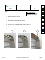
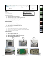
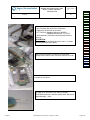
2.4 IDENTIFICATION
All phones are identified with an identification label sticked on the antenna.
2.4.1 Illustration
$
$
%
%
'
&
2.4.2 Desrcription
a1 : IMEI (Bar Code)
a2 : IMEI (15 characters) / Description card SIM
b1 : Reference of product ( Bar Code )
b2 : Reference of product / Aesthetics ( 9 caractères)
c1 : Production date (date code) / Production Level – Geographic indication of manufacture
Ex : F274/02 = (F) fabrication area ( F : Fougères ), (274) days of year, (02) last digit of hear(02®2002).
d1 : Logo and agreement.
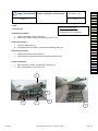
2.4.3 Description after repair
A new sticker is positioned by the Repair Center on the antenna:
This extra line will appear if the mobile has already been repaired.
- CRA XXX -> N° de CRA.
- 260/03 -> Date of repair (260), repairing day (03), last digit of year (03->2003).
Contents
REF MTB DTS 8- Indice B - February 21 2006
Page 2-9
Site technical documentation myC2-3
2.5 PHONE BLOCK DIAGRAM
2.5.1 block diagram
2.5.2Standards and environment
The phone complies with the following standards.
Directive EEC 1999 / 5 / CE
Safety (security) EN 60950
CEM EN 301 489-1 / EN 301 489-7
Voltage 73 / 23 / EEC
Network 3GPP TS 51.010-1 v 5.2.0 with included GCF-CC V 3.10.0
Requirements GT01 v 4.7.0 / TBR 19 edition 5 / TBR 20 edition 3
TBR 31 edition 2 / TBR 32 edition 2 / EN 301 419-1 / EN 301511
Health EN 50360 / EN 50361
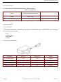
2.6 EQUIPEMENTS
The description and operation of SAGEM myC2-3 are given in the "User’s handbook" supplied with the handset. This
chapter only describes equipment that operates with the myC2-3 handset.
2.6.1 Battery packs
Contents
REF MTB DTS 8- Indice B - February 21 2006
Page 2-10
Site technical documentation myC2-3
2.6.1.1 Charactéristics
Designation
Technology
Weight
Voltage
Capacity
2.6.1.2Description
Li-ion type batteries are used. They are rechargeable using:
- mains power supply module.
Batteries caution use:
·Store the batteries in a dry and cool place (excessive cold and heat damage the batteries reliability).
·They must never be stored in bulk, even the rejects, to avoid any short circuits.
·Do not dismantle the battery packs. (Li-Ion regulations).
·Only use original mains power supply module.
Contents
REF MTB DTS 8- Indice B - February 21 2006
Page 2-11
Site technical documentation myC2-3
2.6.1.3Charging time
The following table shows typical charging times for different batteries.
Battery : Li-Ion 650mAh
Charger
simple unregulated chargers 230
Voltage
230 V (110V)
Charging times
2h
1h 45
2.6.2 Mains modules
2.6.2.1 Description
These mains power supply modules accept large dynamic variations in the power supply network. They are available
for a number of connector types:
- E.E.C,
- United Kingdom
- United States,
- Australia.
2.6.2.2 Travel mains modules
Designation
Weight (g)
Volume (cm3)
Voltage
US Power supply
125
65
110/230 V
UK Power supply
110
90
110/230 V
AUS Power supply
100
75
110/230 V
EEC Power supply
100
75
110/203 V
Contents
REF MTB DTS 8- Indice B - February 21 2006
Page 2-12
Site technical documentation myC2-3
2.6.2.2 Simple mains modules
Designation
Weight (g)
Volume (cm3)
Voltage
AUS Main module
190
105
230 V
CE Main module
180
85
230 V
charger block angled
180
85
240v
UK Main module
180
120
230 V
US Main module
210
105
110 V
Contents
REF MTB DTS 8- Indice B - February 21 2006
Page 2-13
Site technical documentation myC2-3
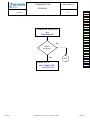
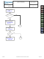
CHAPTER 3 - SYMPTOMS
3.1 GENERAL
After you have received the customer return sheet (Proc Sheet 3 02), carry out the troubleshooting
procedure.
This chapter will help you to identify the defective element(s), using the troubleshooting table.
It contains flow charts broken down by fault type. Each flow chart describes the procedure to be
followed and contains cross references to tests or maintenance.
These flow charts should be followed in full. After a reference to a removal/replacement sheet or to a
test to be carried out, you should return to the initial flow chart and continue the search until
reaching a final conclusion.
The conclusion of each troubleshooting procedure is :
·Return to SAGEM =The Return to the SAGEM centre can concern either the card, or the
radiotelephone according to instructions given to the Centres of repair.
·Delivery to the customer
The mobiles will not be refurbished without a special and wtitten authorisation .
Contents
REF MTB DTS 8- Indice B - February 21 2006
Page 3-1
Site technical documentation myC2-3
Visual test
Customer fault verification
Default
confirmed?
No
Yes
Standard test
Yes
Software inspection - Update
Default
found ?
No
Repairing => symptom sheet
Standard test
No
No
Default
> Level 2 ?
Mobile
OK?
No
Yes
Yes
Return to
Sagem
Contents
> 1 return
no found ?
Yes
Delivery to
customer
REF MTB DTS 8- Indice B - February 21 2006
Return to
Sagem
Page 3-2
Site technical documentation myC2-3
Visual test :
-Connector condition (in / out connector, battery, SIM)
-keypad concdition (elastomer,inscription)
-Pane condition
-Plug and position of battery
-SIM card position
-Oxidation
-Charger test
Standard test :
-Display test : Hot Line menu
-Contrast control
-All keypad keys test (check bips keys)
-Audio and radio test
-Battery charge test
-Vibrating device test : Hot Line menu
Software inspection :
For all mobiles to repair, the checking by SMT is mandatory (Test Sheet 01).
Contents
REF MTB DTS 8- Indice B - February 21 2006
Page 3-3
Site technical documentation myC2-3
3.2LIST OF REPORTED DEFECTS
The following is a list of defects that may be reported :
Default
Anomaly
Procédure
A1
No power up
Symp sheet 04
A2
No display up
Symp sheet 04
A3
Freezes up
Symp sheet 04
A5
Broken LCD
Proc sheet 2 02
A6
Line or digit missing
Symp sheet 04
A10
broken or missing antenna
Proc sheet 1 02
B1
Defective contact battery
Symp sheet 01
B4
Defective charge icon display
Symp sheet 01
B7
Autonomy
Symp sheet 01
B8
Electrically defective battery
Symp sheet 01
Mechanical problem on lock
B9
Proc sheet 0 01
battery
B10
Broken battery
Test sheet 03
B11
Defective charger
Test sheet 02
B12
Broken charger
Test sheet 02
B13
Intermittent cut with reboot
Symp sheet 02
B14
Contents
Intermittent cut without reboot
Symp sheet 02
C1
Not functioning keyboard
Symp sheet 05
C2
Lateral key problem
Symp sheet 05
D7
Post code
Test sheet 01
D9
Unknown battery
Test sheet 03
E1
Defective loudspeaker (hails)
Symp sheet 08
REF MTB DTS 8- Indice B - February 21 2006
Page 3-4
Site technical documentation myC2-3
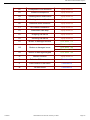
Contents
E2
Loudspeaker voice distortion
Symp sheet 08
E3
Defective microphone
Symp sheet 08
E4
Vibrating device malfunction
Symp sheet 08
E5
Vibrating device malfunction
Symp sheet 07
E6
Defective audio connector
Symp sheet 08
F1
No network localisation
Symp sheet 02
F2
Intermittent calls drop
Symp sheet 02
F5
Outgoing call failure
Symp sheet 02
F6
Incoming call failure
Symp sheet 02
G1
Broken or damaged window
Proc sheet 1 12
G2
Broken or damaged cover
Proc sheet 1 01
Proc sheet 1 06
Proc sheet 1 10
G5
Broken or damaged keypad
Proc sheet 1 04
I3
Monetic function
Symp sheet 03
I5
Defective SIM connector
Test sheet 01
I7
Lack function in the menu
Test sheet 01
I8
No fault found
Test sheet 01
REF MTB DTS 8- Indice B - February 21 2006
Page 3-5
Site technical documentation myC2-3
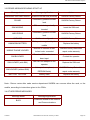
3.3 ERROR MESSAGES DURING START UP
Message drawn
Message signification
WARNING UNTUNED RADIO Invalid EEPROM field (SAGEM)
Action
SAGEM Factory Return
Consistency problem at IMEI
PB IMEI
SAGEM Factory Return
level
SIM card missing or badly
SIM MISSING
Insert the SIM card
inserted
Consistency problem at IMEI
IMEI ERROR
SAGEM Factory Return
level
UNTUNED
Mobile not configured
SAGEM Factory Return
Battery not recognised by the
UNKNOWN BATTERY
Replace the battery
mobile
Number of seizures of sim
SAGEM Factory ReturnNot
locked code exceeded
repair under warranty
MOBILE PHONE LOCKED
Three bad PIN codes have
SIM BLOCKED
Contact the operator
been input
SIM card not adapted to the
SIM LOCKED (with SIM)
Replace the SIM card
operator
Attempt of corruption (
SAGEM Factory ReturnNot
EEPROM fields)
repair under warranty
Battery state
Replace the battery
SIM LOCKED (without SIM)
BATTERY TOO LOW
Nota : Return centre after sales service department SAGEM can concern either the card, or the
mobile, according to instructions given to the CRAs.
3.4 OTHER ERROR MESSAGES
Message drawn
Message signification
Problems related to the network
BUSY
and Communications
Contents
REF MTB DTS 8- Indice B - February 21 2006
Page 3-6
Site technical documentation myC2-3
K.PAD LOCKED PRESS *OK
Keypad locked
Menu not available for this
OPTION NOT AVAILABLE
product version
PROG.KEY NOT VALID
Input Problems
Calculation error with the
ERROR!!
calculator (division by zero)
NOT AVAIL
Not available
PIN ERROR
PIN input problems
PIN2 BLOCKED
Following input errors
PUK ERROR
Following input errors
PUK2 BLOCKED
Following input errors
The phone code input for locking
CODE ERROR
the mobile is incorrect
Call forwarding if the mobile is not
NOT REACHABLE
reachable
Service not implemented in the
NOT AVAIL
network
Contents
REF MTB DTS 8- Indice B - February 21 2006
Page 3-7
Site technical documentation myC2-3
3.5 LIST OF OBSERVED DEFECTS
A SAGEM code is assigned to each confirmed defect. This code should be entered on Proc Sheet 3
01, SAGEM Factory Return, if the phone to be repaired is returned to SAGEM (see chapter 5).
3.6 INFORMATION ABOUT NEW NOTICED FAULTS
Detection by the repair center of new fault shall induce to respect the following procedure
a) The concerned technician fills a precise report using the document NPD report SAV GSM 277 V1
b) Then, this document is transmitted by email to the concerned Area Manager or Support
Engineers for approval. Accordingly, 2 ways are possible :
- The problem is already known by SAGEM, then the mobile have to follow the normal process in
ARC with eventual additional data given by AM or SE
- Return of mobile to MTB is requested.
c) In that second case, the ARC will have to request a specific RMA number for this mobile in order
to facilitate the treatment when arriving in SAGEM.
d) This mobile returned to SAGEM will be swapped following ARCs habitual process for MTB return
but will be MANDATORY linked to a paper version of the document filled by the technician.
e) The treatment will have to be reproduced on the daily report and will be considered as level 3.
Specified fault code will be then the technically closest one of the noted one, in the grid given by
SAGEM
Contents
REF MTB DTS 8- Indice B - February 21 2006
Page 3-8
Site technical documentation myC2-3
SYMPTOM SHEETS
Contents
REF MTB DTS 8- Indice B - February 21 2006
Page 3-9
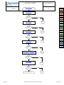
ENDURANCE BATTERY
SYMP SHEET 01
AND CHARGER PROBLEM
myC2-3
1/1
Test the charger
7HVW6KHHW
No
Replace the
charger
Ok ?
yes
Test the consumption
7HVW6KHHW
No
Return to SAV
)LFKH3URF
RX3URF
Ok ?
yes
Symptom
Symp 01
Symp 02
Symp 03
Symp 04
Symp 05
Symp 06
Symp 07
Symp 08
Symp 10
Procédure
Proc 0 01
Proc 1 01
Proc 1 02
Proc 1 03
Proc 1 04
Proc 1 05
Proc 1 06
Proc 1 07
Proc 1 08
Proc 1 09
Proc 1 10
Proc 1 11
Proc 1 12
Proc 2 02
Proc 3 01
Proc 3 02
Proc 4 01
Test
Test 01
Test 02
Test 03
Test 04
Test 05
Test 06
Test the battery
)LFKH7HVW
No
Ok ?
Change the battery
)LFKH3URF
yes
End
Contents
REF MTB DTS 8- Indice B - February 21 2006
Page 3-10
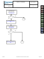
COMMUNICATION
SYMP SHEET 02
PROBLEM
myC2-3
1/1
Realise the WAVETEK
test
7HVW6KHHW
No
Radio
problem ?
Non
Yes
Return to SAV
3URF6KHHW
RX3URF
Contents
REF MTB DTS 8- Indice B - February 21 2006
end
Symptom
Symp 01
Symp 02
Symp 03
Symp 04
Symp 05
Symp 06
Symp 07
Symp 08
Symp 10
Procédure
Proc 0 01
Proc 1 01
Proc 1 02
Proc 1 03
Proc 1 04
Proc 1 05
Proc 1 06
Proc 1 07
Proc 1 08
Proc 1 09
Proc 1 10
Proc 1 11
Proc 1 12
Proc 2 02
Proc 3 01
Proc 3 02
Proc 4 01
Test
Test 01
Test 02
Test 03
Test 04
Test 05
Test 06
Page 3-11
NO FAULT GIVEN
SYMP SHEET 03
Complete function by SMT
myC2-3
1/1
7HVW 6KHHW
Test the charger
7HVW6KHHW
Found
defect ?
Yes
No
Test the Battery
End
7HVW6KHHW
Found
defect ?
Yes
No
Test the consumption
End
7HVW6KHHW
Found
defect ?
Yes
No
Test the display( menu
HOTLINE)
End
7HVW6KHHW
Found
defect ?
Yes
Symptom
Symp 01
Symp 02
Symp 03
Symp 04
Symp 05
Symp 06
Symp 07
Symp 08
Symp 10
Procédure
Proc 0 01
Proc 1 01
Proc 1 02
Proc 1 03
Proc 1 04
Proc 1 05
Proc 1 06
Proc 1 07
Proc 1 08
Proc 1 09
Proc 1 10
Proc 1 11
Proc 1 12
Proc 2 02
Proc 3 01
Proc 3 02
Proc 4 01
Test
Test 01
Test 02
Test 03
Test 04
Test 05
Test 06
No
Test the video/photos functions
End
7HVW6KHHW7HVWVKHHW
Found
defect
Yes
No
Test the radio
End
7HVW6KHHW
Found
defect
Yes
No
Return to the client
Contents
End
REF MTB DTS 8- Indice B - February 21 2006
Page 3-12
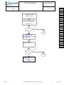
DISPLAY PROBLEM
myC2-3
SYMP SHEET 04
1/1
Test the display with the
Hot Line menu
Black/color screen
7HVW6KHHW
yes
Ok ?
No
end
Change the display
3URF6KHHWRU
Test the display with the
Hot Line menu
7HVW6KHHW
yes
Ok ?
Symptom
Symp 01
Symp 02
Symp 03
Symp 04
Symp 05
Symp 06
Symp 07
Symp 08
Symp 10
Procédure
Proc 0 01
Proc 1 01
Proc 1 02
Proc 1 03
Proc 1 04
Proc 1 05
Proc 1 06
Proc 1 07
Proc 1 08
Proc 1 09
Proc 1 10
Proc 1 11
Proc 1 12
Proc 2 02
Proc 3 01
Proc 3 02
Proc 4 01
Test
Test 01
Test 02
Test 03
Test 04
Test 05
Test 06
No
Return to SAGEM SAV
3URF6KHHWRU
Contents
en
d
REF MTB DTS 8- Indice B - February 21 2006
Page 3-13
KEYPAD PROBLEM
SYMP SHEET 05
myC2-3
1/1
Activate the « Bip
touch » function
Test the keypad listening
the « BIP touch
yes
Ok ?
No
end
Change
the dome métal
3URF6KHHWRU
RURU
Retest the keypad
Symptom
Symp 01
Symp 02
Symp 03
Symp 04
Symp 05
Symp 06
Symp 07
Symp 08
Symp 10
Procédure
Proc 0 01
Proc 1 01
Proc 1 02
Proc 1 03
Proc 1 04
Proc 1 05
Proc 1 06
Proc 1 07
Proc 1 08
Proc 1 09
Proc 1 10
Proc 1 11
Proc 1 12
Proc 2 02
Proc 3 01
Proc 3 02
Proc 4 01
Test
Test 01
Test 02
Test 03
Test 04
Test 05
Test 06
yes
Ok ?
No
end
Return to SAV
3URF6KHHW
RU
Contents
REF MTB DTS 8- Indice B - February 21 2006
Page 3-14
RING TONES PROBLEM
SYMP SHEET 06
myC2-3
1/1
Select a ringtone in the Menu
6HWWLQJVRXQGVULQJWRQHVFDOO
yes
Ringtone Ok ?
end
No
Change the speaker
3URF6KHHW
yes
Ringtone Ok ?
No
Return to SAGEM
)LFKH3URF
RX3URF
Contents
REF MTB DTS 8- Indice B - February 21 2006
end
Symptom
Symp 01
Symp 02
Symp 03
Symp 04
Symp 05
Symp 06
Symp 07
Symp 08
Symp 10
Procédure
Proc 0 01
Proc 1 01
Proc 1 02
Proc 1 03
Proc 1 04
Proc 1 05
Proc 1 06
Proc 1 07
Proc 1 08
Proc 1 09
Proc 1 10
Proc 1 11
Proc 1 12
Proc 2 02
Proc 3 01
Proc 3 02
Proc 4 01
Test
Test 01
Test 02
Test 03
Test 04
Test 05
Test 06
Page 3-15
VIBRATING DEVICE
SYMP SHEET 07
PROBLEM
myC2-3
1/1
Test the vibrating device
With the HOT LINE
7HVW6KHHW
yes
Ok ?
No
end
Change the vibrating device
3URF6KHHWRU
Test the vibrating device
With the HOT LINE
menu
7HVW6KHHW
Symptom
Symp 01
Symp 02
Symp 03
Symp 04
Symp 05
Symp 06
Symp 07
Symp 08
Symp 10
Procédure
Proc 0 01
Proc 1 01
Proc 1 02
Proc 1 03
Proc 1 04
Proc 1 05
Proc 1 06
Proc 1 07
Proc 1 08
Proc 1 09
Proc 1 10
Proc 1 11
Proc 1 12
Proc 2 02
Proc 3 01
Proc 3 02
Proc 4 01
Test
Test 01
Test 02
Test 03
Test 04
Test 05
Test 06
yes
Ok ?
No
Return to SAV
)LFKH3URF
RX3URF
Contents
end
REF MTB DTS 8- Indice B - February 21 2006
Page 3-16
AUDIO PROBLEM
myC2-3
SYMP SHEET 08
1/1
Realise a Wavetek
Test
7HVW6KHHW
No
Audio problem?
yes
Replace the microphone
And / or the speaker
3URF6KHHW
3URF
end
Realise a Wavetek
Test
7HVW6KHHW
yes
Symptom
Symp 01
Symp 02
Symp 03
Symp 04
Symp 05
Symp 06
Symp 07
Symp 08
Symp 10
Procédure
Proc 0 01
Proc 1 01
Proc 1 02
Proc 1 03
Proc 1 04
Proc 1 05
Proc 1 06
Proc 1 07
Proc 1 08
Proc 1 09
Proc 1 10
Proc 1 11
Proc 1 12
Proc 2 02
Proc 3 01
Proc 3 02
Proc 4 01
Test
Test 01
Test 02
Test 03
Test 04
Test 05
Test 06
Ok ?
No
Return to SAV
3URF6KHHW
RU3URF
Contents
end
REF MTB DTS 8- Indice B - February 21 2006
Page 3-17
LOUDSPEAKER PROBLEM
myC2-3
SYMP SHEET 10
1/1
Do the wavetek Test
7HVW6KHHW
Replace the loudspeaker
352&6+((7
RU
Symptom
Symp 01
Symp 02
Symp 03
Symp 04
Symp 05
Symp 06
Symp 07
Symp 08
Symp 10
Procédure
Proc 0 01
Proc 1 01
Proc 1 02
Proc 1 03
Proc 1 04
Proc 1 05
Proc 1 06
Proc 1 07
Proc 1 08
Proc 1 09
Proc 1 10
Proc 1 11
Proc 1 12
Proc 2 02
Proc 3 01
Proc 3 02
Proc 4 01
Test
Test 01
Test 02
Test 03
Test 04
Test 05
Test 06
Do the Wavetek test
7(676+((7
Return to SAGEM
SAGEM
SAV
352&6+((7
3URF6KHHW
RU
Contents
REF MTB DTS 8- Indice B - February 21 2006
Page 3-18
Site technical documentation myC2-3
CHAPTER 4 - TESTS AND CHECKS
4.1 ABOUT TESTS
Tests and checks are made after the troubleshooting procedures (chapter 3) and before the
maintenance procedures (chapter 5).
They are broken down into modules and are sorted by types of confirmed faults. The user must be
equipped with special test tools in order to carry out the tests.
4.2 TEST TOOLS
The references of SAGEM tools, listed hereafter, are given in Appendix 1 : Composition table.
The following test tools are necessary :
-the ARC downloading kit, including the test case provided with:
·the data cable (to PC),
·the retrofit cable,
·the mains power supply module.
·Retrofit adapter
-the radio test bench, provided with:
·SIM card of test.
·myC2-3 calibration tool
·Adjustable regulate power supply 0-15V / 4A
·Wavetek 4107
-CADEX C7000 / C7200 / ASTRATEK with myC3-2 adapter
·Charger test kit
·Voltmeter (minimum impedance : 20 KW per Volt in DC)
·Ampermiter
-an IMEI labels printing station, including :
· Printer,
· Roll of labels,
· Connecting cable for PC (parallel printer cable),
· Printing software,
4.3 INSTALLING ON A WORKSTATION
4.3.1 Minimum required configuration
The minimum configuration of the workstation is :
- Processor 1Ghz,
- 128 Mbytes of RAM,
- Windows 2000, Windows XP,
- 2.1 Gbytes hard disk (1 Gbytes available),
- 1 parallel port and 2 serials port.
- USB port.
- Network card, sound card.
Contents
REF MTB DTS 8- Indice B - February 21 2006
Page 4-1
Site technical documentation myC2-3
4.3.2 Installing the ARC downloading kit
The ARC downloading kit interfaces the SMT software with the phone to be repaired.
-Connect the 9-pin SUB-D connector to the PC serial port (COM1).
-Connect the power supply module to the mains power outlet.
-Connect the phone to be repaired to the system connector.
4.3.3 SMT functions
The SMT maintenance software can:
-Download new software if needed
-Configure default values and checks them.
-Unblocked the " PHONE CODE "
-Delete the customer directory and SMS
-Print identification labels.
-Make a electronic board swap.
-Adjust the display contrast
-Read the Site Technical Documentation ( manual of repair)
-Select a test sequence
The procedures for using these functions are described in TEST Sheet 01.
Contents
REF MTB DTS 8- Indice B - February 21 2006
Page 4-2
Site technical documentation myC2-3
TEST SHEETS
Contents
REF MTB DTS 8- Indice B - February 21 2006
Page 4-3
TEST AND CHECK BY SMT
TEST SHEET 01
myC2-3
1/7
!
"
#
$
%
! "
(
1
#
2
)
$
#)*+,-
.
/-,)#0 &/
3
4
5
#
#)*+,-
&
%'
'
%
.
,- -! -
#
6
!7-
.
8,)
9 #
!7-
& %
-:+-
-
"
Test
Test 01
Test 02
Test 03
Test 04
Test 05
Test 06
Procédure
Proc 0 01
Proc 1 01
Proc 1 02
Proc 1 03
Proc 1 04
Proc 1 05
Proc 1 06
Proc 1 07
Proc 1 08
Proc 1 09
Proc 1 10
Proc 1 11
Proc 1 12
Proc 2 02
Proc 3 01
Proc 3 02
Proc 4 01
Symptom
Symp 01
Symp 02
Symp 03
Symp 04
Symp 05
Symp 06
Symp 07
Symp 08
Symp 10
'
.
%
%
!+
;
%
<
3
=
%
!8
" #
Contents
REF MTB DTS 8- Indice B - February 21 2006
Page 4-4
TEST AND CHECK BY SMT
TEST SHEET 01
myC2-3
2/7
!" #
3
3
=
%
=
3
=
3
%
%
%
"
3 >
%
3
?,
3
3
3 >
?
3 >
$
) -)
0
,
%
%
$
Test
Test 01
Test 02
Test 03
Test 04
Test 05
Test 06
Procedure
Proc 0 01
Proc 1 01
Proc 1 02
Proc 1 03
Proc 1 04
Proc 1 05
Proc 1 06
Proc 1 07
Proc 1 08
Proc 1 09
Proc 1 10
Proc 1 11
Proc 1 12
Proc 2 02
Proc 3 01
Proc 3 02
Proc 4 01
Symptom
Symp 01
Symp 02
Symp 03
Symp 04
Symp 05
Symp 06
Symp 07
Symp 08
Symp 10
$
(
1
2
4
Contents
REF MTB DTS 8- Indice B - February 21 2006
Page 4-5
TEST AND CHECK BY SMT
TEST SHEET 01
myC2-3
3/7
!
"
#
Contents
$
REF MTB DTS 8- Indice B - February 21 2006
Test
Test 01
Test 02
Test 03
Test 04
Test 05
Test 06
Procedure
Proc 0 01
Proc 1 01
Proc 1 02
Proc 1 03
Proc 1 04
Proc 1 05
Proc 1 06
Proc 1 07
Proc 1 08
Proc 1 09
Proc 1 10
Proc 1 11
Proc 1 12
Proc 2 02
Proc 3 01
Proc 3 02
Proc 4 01
Symptom
Symp 01
Symp 02
Symp 03
Symp 04
Symp 05
Symp 06
Symp 07
Symp 08
Symp 10
Page 4-6
TEST AND CHECK BY SMT
TEST SHEET 01
myC2-3
4/7
%
&
#
'
(
#
Contents
$
) !
*
REF MTB DTS 8- Indice B - February 21 2006
Test
Test 01
Test 02
Test 03
Test 04
Test 05
Test 06
Procedure
Proc 0 01
Proc 1 01
Proc 1 02
Proc 1 03
Proc 1 04
Proc 1 05
Proc 1 06
Proc 1 07
Proc 1 08
Proc 1 09
Proc 1 10
Proc 1 11
Proc 1 12
Proc 2 02
Proc 3 01
Proc 3 02
Proc 4 01
Symptom
Symp 01
Symp 02
Symp 03
Symp 04
Symp 05
Symp 06
Symp 07
Symp 08
Symp 10
Page 4-7
TEST AND CHECK BY SMT
TEST SHEET 01
myC2-3
5/7
(
+#
*
) !
(
,
Contents
#
-
#
REF MTB DTS 8- Indice B - February 21 2006
Test
Test 01
Test 02
Test 03
Test 04
Test 05
Test 06
Procedure
Proc 0 01
Proc 1 01
Proc 1 02
Proc 1 03
Proc 1 04
Proc 1 05
Proc 1 06
Proc 1 07
Proc 1 08
Proc 1 09
Proc 1 10
Proc 1 11
Proc 1 12
Proc 2 02
Proc 3 01
Proc 3 02
Proc 4 01
Symptom
Symp 01
Symp 02
Symp 03
Symp 04
Symp 05
Symp 06
Symp 07
Symp 08
Symp 10
Page 4-8
TEST AND CHECK BY SMT
TEST SHEET 01
myC2-3
6/7
.
*
/&
0
1
#
Contents
/230*
&
REF MTB DTS 8- Indice B - February 21 2006
#
#
'
%
Test
Test 01
Test 02
Test 03
Test 04
Test 05
Test 06
Procedure
Proc 0 01
Proc 1 01
Proc 1 02
Proc 1 03
Proc 1 04
Proc 1 05
Proc 1 06
Proc 1 07
Proc 1 08
Proc 1 09
Proc 1 10
Proc 1 11
Proc 1 12
Proc 2 02
Proc 3 01
Proc 3 02
Proc 4 01
Symptom
Symp 01
Symp 02
Symp 03
Symp 04
Symp 05
Symp 06
Symp 07
Symp 08
Symp 10
Page 4-9
TEST AND CHECK BY SMT
TEST SHEET 01
myC2-3
7/7
4
#
5
$
#
#
9
/
#
'
3+67 &
!
#
-
Contents
REF MTB DTS 8- Indice B - February 21 2006
08
Test
Test 01
Test 02
Test 03
Test 04
Test 05
Test 06
Procedure
Proc 0 01
Proc 1 01
Proc 1 02
Proc 1 03
Proc 1 04
Proc 1 05
Proc 1 06
Proc 1 07
Proc 1 08
Proc 1 09
Proc 1 10
Proc 1 11
Proc 1 12
Proc 2 02
Proc 3 01
Proc 3 02
Proc 4 01
Symptom
Symp 01
Symp 02
Symp 03
Symp 04
Symp 05
Symp 06
Symp 07
Symp 08
Symp 10
!
Page 4-10
CHARGER TEST
TEST SHEET 02
myC2-3
1/1
Ω
!
!
!
"
#
$
%
&
'
(
!
)
*
Test
Test 01
Test 02
Test 03
Test 04
Test 05
Test 06
Procédure
Proc 0 01
Proc 1 01
Proc 1 02
Proc 1 03
Proc 1 04
Proc 1 05
Proc 1 06
Proc 1 07
Proc 1 08
Proc 1 09
Proc 1 10
Proc 1 11
Proc 1 12
Proc 2 02
Proc 3 01
Proc 3 02
Proc 4 01
Symptom
Symp 01
Symp 02
Symp 03
Symp 04
Symp 05
Symp 06
Symp 07
Symp 08
Symp 10
+ !
!
,
-
.
!
0
1
/!
!
!
Contents
REF MTB DTS 8- Indice B - February 21 2006
!
Page 4-11
BATTERY TEST
TEST SHEET 03
myC2-3
1/1
!
"
"
#
"
*
*
$ %
&" # " " "
+#
# ""
,
# $%
/ 0+ #
"
#
1 2
#
#
%) +$
#
#
3
Ω
$
5 "#
#
#
#
%%
#1
# #1
%
#
&*
%
1
# "
#%
!
%
&/ 0 #) !
# "#
1
" )
#% 2 5
69 5
Contents
.
$ %
6 4( "
#
.+$
-
(
3(
#
&5!7()
)
Ω
1 24 !
#%
1
#
$ %
1
$
(
Ω
.
) +$
'Ω
#
,
)
#%
Test
Test 01
Test 02
Test 03
Test 04
Test 05
Test 06
Procédure
Proc 0 01
Proc 1 01
Proc 1 02
Proc 1 03
Proc 1 04
Proc 1 05
Proc 1 06
Proc 1 07
Proc 1 08
Proc 1 09
Proc 1 10
Proc 1 11
Proc 1 12
Proc 2 02
Proc 3 01
Proc 3 02
Proc 4 01
Symptom
Symp 01
Symp 02
Symp 03
Symp 04
Symp 05
Symp 06
Symp 07
Symp 08
Symp 10
"8 "
"8 "
REF MTB DTS 8- Indice B - February 21 2006
Page 4-12
CONSUMPTION TEST
myC2-3
!
#
1/1
"
$
"
&
'
(
)
!
+
!
,
$
'
%
'
'
' '
*
"
"
(
'
&
-
TEST SHEET 04
'
%
'
Test
Test 01
Test 02
Test 03
Test 04
Test 05
Test 06
Procédure
Proc 0 01
Proc 1 01
Proc 1 02
Proc 1 03
Proc 1 04
Proc 1 05
Proc 1 06
Proc 1 07
Proc 1 08
Proc 1 09
Proc 1 10
Proc 1 11
Proc 1 12
Proc 2 02
Proc 3 01
Proc 3 02
Proc 4 01
Symptom
Symp 01
Symp 02
Symp 03
Symp 04
Symp 05
Symp 06
Symp 07
Symp 08
Symp 10
'
' '
$
.
"
"
/
Contents
!
"
,0
*
REF MTB DTS 8- Indice B - February 21 2006
Page 4-13
HOTLINE MENU
TEST SHEET 05
myC2-3
1/1
!
"
#
$ "
$ " %
&!
#
%
&
#
'
(
•
$ "
)) *
)-
•
(
.
-0. #
+/
•
"
!
+, -
•
!
.
!
(
"
# !
!
*1
*1 .
%
2
&!
#
Test
Test 01
Test 02
Test 03
Test 04
Test 05
Test 06
Procédure
Proc 0 01
Proc 1 01
Proc 1 02
Proc 1 03
Proc 1 04
Proc 1 05
Proc 1 06
Proc 1 07
Proc 1 08
Proc 1 09
Proc 1 10
Proc 1 11
Proc 1 12
Proc 2 02
Proc 3 01
Proc 3 02
Proc 4 01
Symptom
Symp 01
Symp 02
Symp 03
Symp 04
Symp 05
Symp 06
Symp 07
Symp 08
Symp 10
*3
/
"
*1 .
4
$!
*-
- 3 *5-
*-
/ 6
*-
4
3- 65
7 -)
, /-
-3
" (
$
53 ,* .
3%(
Contents
.
/
#
(
!
!
&
REF MTB DTS 8- Indice B - February 21 2006
Page 4-14
RADIO TEST
TEST SHEET 06
myC2-3
Test
Test 01
Test 02
Test 03
Test 04
Test 05
Test 06
Procédure
Proc 0 01
Proc 1 01
Proc 1 02
Proc 1 03
Proc 1 04
Proc 1 05
Proc 1 06
Proc 1 07
Proc 1 08
Proc 1 09
Proc 1 10
Proc 1 11
Proc 1 12
Proc 2 02
Proc 3 01
Proc 3 02
Proc 4 01
Symptom
Symp 01
Symp 02
Symp 03
Symp 04
Symp 05
Symp 06
Symp 07
Symp 08
Symp 10
1/2
! "#
7
6 !"#
$
% &%
'()
&
$
*
#
"
/
+#, - .' +
+,$+
)
3 4
/
6
$
8
3
9
/
:
(
+0- 1+
2
2
5
2
+.1 .7+
5
%
56 ; &
<
0
%
2=
Contents
6&
5
5
2,
>
REF MTB DTS 8- Indice B %'#>.)
- February 21 2006
2 6 " 9 6<&
Page 4-15
RADIO TEST
TEST SHEET 06
myC2-3
2/2
$
% &%
'
+#, - .' +
*
"
$
6
3
&
%
/
&
+,$+
)
3 4
/
Contents
'
'()
+0- 1+
2)
2
5
2
+.1 .7+
%
REF MTB DTS 8- Indice B - February 21 2006
&
Test
Test 01
Test 02
Test 03
Test 04
Test 05
Test 06
Procedure
Proc 0 01
Proc 1 01
Proc 1 02
Proc 1 03
Proc 1 04
Proc 1 05
Proc 1 06
Proc 1 07
Proc 1 08
Proc 1 09
Proc 1 10
Proc 1 11
Proc 1 12
Proc 2 02
Proc 3 01
Proc 3 02
Proc 4 01
Symptom
Symp 01
Symp 02
Symp 03
Symp 04
Symp 05
Symp 06
Symp 07
Symp 08
Symp 10
Page 4-16
Site technical documentation myC2-3
CHAPTER 5 - MAINTENANCE PROCEDURES
5.1 TECHNICAL WORK LEVELS
There are four technical work levels:
-Level 0,
-Level 1,
-Level 2,
-Level 3.
Each level represents a maintenance degree that depends on which elements are to be removed.
Note: Presence or use on the radiotelephone of non genuine element (material and software) leads
automatically the exclusion from SAGEM warranty
5.2 SHORT LOOP PROCESS
1. Initialisation
From the communication by Sagem and the reception of the concerned products by the short loop
process, the Repair Centre shall comply with the above procedure. The application of the Short loop
process will end when received the authorisation of repairing given by Sagem.
2. Administrative checks to be done by the Repair Centre
- Authorisation from Sagem for treating the reference received (Part number)
- Process to be applied : short loop process or normal process (DTS, Normal, etc…). The Repair
Centre shall check if the product received has to be treated according to the short loop process.
- Controls on the warranty conditions and DOA conditions (if the Repair Centre is authorised)
communicated by Sagem.
3. Tests and controls :
- Checks if there are no external shocks or oxidation marks ( the covers shall be dismantled in case
of exchangeable covers)
- Checks and confirmation of the defect (real call with SIM, functional test keypad , display, vibrating
device, etc…)
- Check the concordance between the defect declared by the end-user and the defect observed
- Call back of the end-user or dealer (as far as possible) either in case of misunderstanding of the
defect declared by the end-user or in case of the non observation of the defect. (see the appendix
“Additional information about the No Fault Found –NFF-> at the end of this document allowing
according to the case to understand the return of the product)
If any doubts occurred concerning out of warranty products received, the Repair Centre shall send
to Sagem Montauban (with knowledge to the Area Manager and Support Engineer) the photo of the
defect.
N.B :
Contents
REF MTB DTS 8- Indice B - February 21 2006
Page 5-1
Site technical documentation myC2-3
-The handsets shall not be dismantled (by using screwdrivers) except previous request from
Sagem.
-The Repair Centre will not make any Repair (such as spare parts exchange or software
upgrade) except previous communication of Sagem. The exchanges of handsets or accessories are
the only intervention authorised.
4. Exchange by the Repair Centre
- The Repair Centre will use the products delivered for swap to the Repair Centre for exchanging the
products to the end-users (except particular process defined by Sagem).
- The under- warranty handsets and accessories received shall be exchanged to the end-user.
- The under- warranty handsets and accessories declared No Fault Found (NFF) shall be
exchanged to the end-users except previous communication of Sagem.
- The Out of warranty handsets and accessories (oxidation, shocks, …) will be repaired by the
Repair Centre after acceptation by the customer of an estimate according to the Sagem out of
warranty repair prices communicated.
- The under- warranty and out of warranty handsets shall be sent to Sagem Montauban.
- In the frame of the Short loop process, there is no level 1 (L1) intervention
5. Reports
An exchange of an handset and its accessories shall be codified Level 3 (L3)
An accessory exchange shall be codified Level 0 (L0).
The Repair Centre shall capture all the information required for issuing and sending the Repair
Reports and Status reports according to the Contractual frequency defined. The Reports shall
includes the products treated by the Repair Centre under- warranty or out of warranty.
6. Procedure
From the beginning date of the Short loop process application and minimum each week, the Repair
Centre shall ship the products (handsets and accessories) to Sagem Montauban.
6.1. Handsets :
- MRA Procedure for the after-Sales products ( one MRA number for the products concerned by the
short loop).
- MRA Procedure for DOA products ( one MRA DOA number for the products concerned by the
short loop) if the Repair Centre is authorised to treat the DOA products.
The MRA request shall be sent to Sagem Montauban (with knowledge to the Area Manager and
Support Engineer).
The shipment of products to Sagem Montauban shall comply with the MRA procedure. Furthermore
each products shall be sent with the Return Product Sheet filled in indicating the defect declared by
the end-user and the defect observed by the Repair Centre (Sagem Defect codes).
The NFF products sent to Sagem Montauban shall be identified by using separate package.
Furthermore this products shall be sent with the complete description of the defect declared by the
end-user ( not codified).
The accessories received by the Repair Centre shall be sent to Sagem Montauban sent back
Contents
REF MTB DTS 8- Indice B - February 21 2006
Page 5-2
Site technical documentation myC2-3
attached with the handset ( not connected to the handset).
6.2. Accessories :
For the accessories received without the handsets, the procedure is the following:
Accessories return procedure to Sagem Montauban to be used. The Repair Centre shall indicate on
the parcel Accessories + model (ex : myC 3-2) for the accessories received in the Repair Centre
without the handsets.
7. Sagem Montauban
Sagem Montauban will ship back to the Repair Centre the same quantity of handsets and
accessories as the quantity received.
8 Additional information about the no fault found
In any case: Ask to the end-user the frequency of the defect and the circumstances of its apparition
(during an incoming or out-going call, while playing, while downloading, etc.). Try to answer the
questions: Where? When? How?
· If the customer complains about a “Power supply / charging” failure : (shutting down of the
mobile, problem of booting, etc.);
o During which operation ? In which circumstances ?
o What is the state of the battery and the charger before shipment to the repair centre ?
If the mobile shuts down by itself, must he enter his code pin, adjust the date and the hour when
rebooting the phone?
·If the customer complains about a communication problem:
oWhat are his residence zone and the reception level of the mobile (Number of receipt bar);
oWhat is the state of the battery when the defect appears?
oIn case of loss of communication :
§With or without total extinction of the mobile?
§Does the loss of communication occur always in the same place and with the same person?
§Does the loss of communication occur while browsing in the menus, during the
communication, or during playing or downloading?
·If the customer complains about a problem of blockage of key of the keyboard:
oIn which circumstances does the problem occur?
oDid he activate the keypad locking ?
oDid he change or remove the upper cover ?
oWhich are the non functioning keys ?
5.3 MAINTENANCE TOOLS
The following tools are necessary to carry out maintenance operations :
Contents
REF MTB DTS 8- Indice B - February 21 2006
Page 5-3
Site technical documentation myC2-3
- Gloves
- Tweezers
- Soldering iron
Contents
REF MTB DTS 8- Indice B - February 21 2006
Page 5-4
Site technical documentation myC2-3
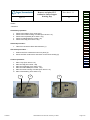
LEVEL 0 MAINTENANCE
Contents
REF MTB DTS 8- Indice B - February 21 2006
Page 5-5
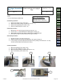
5HPRYHDQGSODFHWKHEDWWHU\
Proc sheet 0 01
myC2-3
1/1
7RROV
-Not applicable
3UHOLPLQDU\RSHUDWLRQ
-Swith off the mobile phone
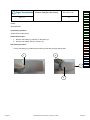
5HPRYDOSURFHGXUH
1. Remove the battery by pressing on the button (1).
2. Remove the battery with two notches (2)
3ODFHPHQWSURFHGXUH
1. Place the battery by positioning the bottom(3) first and press(4) until the blot.
Procedure
Proc 0 01
Proc 1 01
Proc 1 02
Proc 1 03
Proc 1 04
Proc 1 05
Proc 1 06
Proc 1 07
Proc 1 08
Proc 1 09
Proc 1 10
Proc 1 11
Proc 1 12
Proc 2 02
Proc 3 01
Proc 3 02
Proc 4 01
Symptom
Symp 01
Symp 02
Symp 03
Symp 04
Symp 05
Symp 06
Symp 07
Symp 08
Symp 10
Test
Test 01
Test 02
Test 03
Test 04
Test 05
Test 06
Contents
REF MTB DTS 8- Indice B - February 21 2006
Page 5-6
Site technical documentation myC2-3
LEVEL 1 MAINTENANCE
Contents
REF MTB DTS 8- Indice B - February 21 2006
Page 5-7
5HPRYHDQGSODFHWKHDVVHPEOHG
ORZHUKRXVLQJRIPRELOH
Procedure
Proc 0 01
Proc 1 01
Proc 1 02
Proc 1 03
Proc 1 04
Proc 1 05
Proc 1 06
Proc 1 07
Proc 1 08
Proc 1 09
Proc 1 10
Proc 1 11
Proc 1 12
Proc 2 02
Proc 3 01
Proc 3 02
Proc 4 01
Symptom
Symp 01
Symp 02
Symp 03
Symp 04
Symp 05
Symp 06
Symp 07
Symp 08
Symp 10
Test
Test 01
Test 02
Test 03
Test 04
Test 05
Test 06
Proc sheet 1 01
myC2-3
1/1
7RROV
-Cross shared screwing , Fixture for screwing
3UHOLPLQDU\RSHUDWLRQ
Remove the battery (Proc sheet 0 01)
5HPRYDOSURFHGXUH
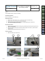
1.
2.
3.
4.
Remove the mask antenna screw (1) and remove the screw antenna (2).
Remove the 3 torx screw (3) on the lower housing (4).
Take apart delicately the assembled lower housing beginning by the bottom (5).
Take off the assembled lower housing.
3ODFHPHQWSURFpGXUH
1. Place the new assembled lower housing (4) by positioning at first the top then press on the
bottom for assembled.
2. Place the mobile on the tool and screw the antenna (torque of 0.08 N.m ). Add the mask
antenna screw.
3. Screw the 3 torx fixing screws (torque of 0.09 N.m ).
)XUWKHURSHUDWLRQV
1. Place the battery (Proc sheet 0 01).
Contents
REF MTB DTS 8- Indice B - February 21 2006
Page 5-8
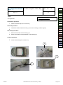
5HPRYHDQGSODFHWKHDQWHQQD
myC2-3
Proc sheet 1 02
1/1
7RROV
Risk of the procedure :
Warning the screwing (0.08 and 0.09N.m)
-Cross shaped screw
3UHOLPLQDU\RSHUDWLRQ
1. Remove of battery. (Proc sheet 0 01)
2. Remove of lower housing of mobile (Proc sheet 1 01).
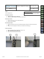
5HPRYDOSURFHGXUH
1. Remove the fixing screw (1) of the antenna (2).
2. Remove the antenna(2).
3ODFHPHQWSURFHGXUH
1. Position the antenna (2) in its slot carefully inserting correctly the contact of the antenna
(3).
2. Position and screw (torque of 0.08 N.m ) the antenna screw fixing (1).
)XUWKHURSHUDWLRQV
1. Place the lower housing of mobile (Proc sheet 1 01).
2. Place of the battery (Proc sheet 0 01)
3. Carry out the radio test (Test sheet 04).
Contents
REF MTB DTS 8- Indice B - February 21 2006
Procedure
Proc 0 01
Proc 1 01
Proc 1 02
Proc 1 03
Proc 1 04
Proc 1 05
Proc 1 06
Proc 1 07
Proc 1 08
Proc 1 09
Proc 1 10
Proc 1 11
Proc 1 12
Proc 2 02
Proc 3 01
Proc 3 02
Proc 4 01
Symptom
Symp 01
Symp 02
Symp 03
Symp 04
Symp 05
Symp 06
Symp 07
Symp 08
Symp 10
Test
Test 01
Test 02
Test 03
Test 04
Test 05
Test 06
Page 5-9
5HPRYHDQGSODFHWKH3OXJVKRFN
DEVRUEHU
myC2-3
Proc sheet 1 03
1/1
7RROV
-Tweezers
3UHOLPLQDU\RSHUDWLRQ
1. Remove of battery. (Proc sheet 0 01)
2. Remove of lower housing of mobile (Proc sheet 1 01).
Risk of the procedure :
Damage plug shock absorber.
Damage the lower housing
5HPRYDOSURFHGXUH
1. Remove the plug shock absorber (1) with tweezers.
3ODFHPHQWSURFHGXUH
1. Position the plug shock absorber (1) with tweezers.
2. Push the plug shock absorber with tweezers for good positioning (3).
)XUWKHURSHUDWLRQV
1. Place the lower housing of mobile (Proc sheet 1 01).
2. Place of the battery (Proc sheet 0 01)
Contents
REF MTB DTS 8- Indice B - February 21 2006
Procedure
Proc 0 01
Proc 1 01
Proc 1 02
Proc 1 03
Proc 1 04
Proc 1 05
Proc 1 06
Proc 1 07
Proc 1 08
Proc 1 09
Proc 1 10
Proc 1 11
Proc 1 12
Proc 2 02
Proc 3 01
Proc 3 02
Proc 4 01
Symptom
Symp 01
Symp 02
Symp 03
Symp 04
Symp 05
Symp 06
Symp 07
Symp 08
Symp 10
Test
Test 01
Test 02
Test 03
Test 04
Test 05
Test 06
Page 5-10
5HPRYHDQGSODFHWKHNH\ERDUG
myC2-3
Procedure
Proc 0 01
Proc 1 01
Proc 1 02
Proc 1 03
Proc 1 04
Proc 1 05
Proc 1 06
Proc 1 07
Proc 1 08
Proc 1 09
Proc 1 10
Proc 1 11
Proc 1 12
Proc 2 02
Proc 3 01
Proc 3 02
Proc 4 01
Symptom
Symp 01
Symp 02
Symp 03
Symp 04
Symp 05
Symp 06
Symp 07
Symp 08
Symp 10
Test
Test 01
Test 02
Test 03
Test 04
Test 05
Test 06
Proc sheet 1 04
1/1
7RROV
- Not applicable
3UHOLPLQDU\RSHUDWLRQ
1. Remove the battery (Proc sheet 0 01)
2. Remove the lower housing of mobile (Proc sheet 1 01).
Risk of the procedure :
Damage the MMI. board
Damage the flex (connector)
5HPRYDOSURFHGXUH
1. Lift up the MMI board (1).
2. Put upside down the mobile. Let the keyboard falling down (2)
3ODFHPHQWSURFHGXUH
1. Position the keyboard in its place (3).
2. Verify that the keyboard sits well on the locating points(4,5,6)
)XUWKHURSHUDWLRQV
1. Place the lower housing of mobile (Proc sheet 1 01).
2. Place of the battery (Proc sheet 0 01)
Contents
REF MTB DTS 8- Indice B - February 21 2006
Page 5-11
5HPRYHDQGSODFHWKHPLFUR
UXEEHU
myC2-3
Proc sheet 1 05
1/1
7RROV
Risk of the procedure :
Put the micro rubber back to front
-Tweezers
3UHOLPLQDU\RSHUDWLRQ
1. Remove the battery (Proc sheet 0 01)
2. Remove the lower housing of mobile (Proc sheet 1 01).
5HPRYDOSURFHGXUH
1. Take the micro rubber with the tweezers (1)
3ODFHPHQWSURFHGXUH
1. Put the micro rubber (1) set up the micro (2).
2. Chek the micro rubber is well positinned (3)
)XUWKHURSHUDWLRQV
1. Place the lower housing of mobile (Proc sheet 1 01).
2. Place of the battery (Proc sheet 0 01)
Contents
REF MTB DTS 8- Indice B - February 21 2006
Procedure
Proc 0 01
Proc 1 01
Proc 1 02
Proc 1 03
Proc 1 04
Proc 1 05
Proc 1 06
Proc 1 07
Proc 1 08
Proc 1 09
Proc 1 10
Proc 1 11
Proc 1 12
Proc 2 02
Proc 3 01
Proc 3 02
Proc 4 01
Symptom
Symp 01
Symp 02
Symp 03
Symp 04
Symp 05
Symp 06
Symp 07
Symp 08
Symp 10
Test
Test 01
Test 02
Test 03
Test 04
Test 05
Test 06
Page 5-12
5HPRYHDQGSODFHRI)SF
FRQGXFWLYHIRDP
Proc sheet 1 06
myC2-3
1/1
7RROV
-Tweezers
3UHOLPLQDU\RSHUDWLRQ
1. Remove the battery (Proc sheet 0 01)
2. Remove the lower housing of mobile (Proc sheet 1 01).
5HPRYDOSURFHGXUH
1. Take the Fpc conductive foam with the tweezers (1)
3ODFHPHQWSURFHGXUH
1. Position the Fpc conductive foam in its place (2).
2. Check the Fpc conductive foam is well positioned on the lower housing (3)
)XUWKHURSHUDWLRQV
1. Place the lower housing of mobile (Proc sheet 1 01).
2. Place of the battery (Proc sheet 0 01)
Contents
REF MTB DTS 8- Indice B - February 21 2006
Procedure
Proc 0 01
Proc 1 01
Proc 1 02
Proc 1 03
Proc 1 04
Proc 1 05
Proc 1 06
Proc 1 07
Proc 1 08
Proc 1 09
Proc 1 10
Proc 1 11
Proc 1 12
Proc 2 02
Proc 3 01
Proc 3 02
Proc 4 01
Symptom
Symp 01
Symp 02
Symp 03
Symp 04
Symp 05
Symp 06
Symp 07
Symp 08
Symp 10
Test
Test 01
Test 02
Test 03
Test 04
Test 05
Test 06
Page 5-13
5HPRYHDQGSODFHWKH00L
ERDUG
myC2-3
Proc sheet 1 07
1/1
7RROV
-Tweezers , Gloves
Risk of the procedure :
Damage the components o MMI boar
3UHOLPLQDU\RSHUDWLRQ
1. Remove the battery (Proc sheet 0 01)
2. Remove the lower housing of mobile (Proc sheet 1 01).
5HPRYDOSURFHGXUH
This procedure must be performed by a technician with gloves.
1. Make control lever with the tweezers to disconnect the FPC connective ( 1 ) and care of
not damaging components.
2. Loosen the Fpc (2).
3. Remove the MMI board of the lower housing.
3ODFHPHQWSURFHGXUH
1. Position the MMI board (3) in the lower housing. Warning to the correctly positioning of
keyboard (Fiche Prod 1 04).
2. Position and connect the FPC (2).
)XUWKHURSHUDWLRQV
1. Place the lower housing of mobile (Proc sheet 1 01).
2. Place of the battery (Proc sheet 0 01)
Contents
REF MTB DTS 8- Indice B - February 21 2006
Procedure
Proc 0 01
Proc 1 01
Proc 1 02
Proc 1 03
Proc 1 04
Proc 1 05
Proc 1 06
Proc 1 07
Proc 1 08
Proc 1 09
Proc 1 10
Proc 1 11
Proc 1 12
Proc 2 02
Proc 3 01
Proc 3 02
Proc 4 01
Symptom
Symp 01
Symp 02
Symp 03
Symp 04
Symp 05
Symp 06
Symp 07
Symp 08
Symp 10
Test
Test 01
Test 02
Test 03
Test 04
Test 05
Test 06
Page 5-14
5HPRYHDQGSODFHPHWDOGRPH
myC2-3
Proc sheet 1 08
1/1
2XWLOODJHV
-Tweezers , Gloves , Fixture Metal dome (252254450)
Risk of the procédure :
Damage the component of MMI board
3UHOLPLQDU\RSHUDWLRQ
1. Remove the battery (Proc sheet 0 01).
2. Remove the lower housing of mobile (Proc sheet 1 01).
3. Remove MMI board (Proc sheet 1 07).
5HPRYDOSURFHGXUH
This procedure must be performed by a technician with gloves.
1. Take care of the component metal dome (1) with a tweezers.
2. Put the board upside down (2), take the metal dome (3).
3. Carefully check there is no spot cleft on the board (4).
3ODFHPHQWSURFHGXUH
:DUQLQJ The metal dome is not reusable, it must be replaced by a new metal dome.
1. Position the MMI board in the tool of metal dome (252254450.)
2. Position the metal dome on the MMI board.
3. Take off the board of the tool , put the board upside down and puss part (5)
)XUWKHURSHUDWLRQ
1. Place the keyboard ( Proc sheet 1 04)
2. Place the board MMI (Proc sheet 1 07)
3. Place the lower housing of mobile (Proc sheet 1 01).
4. Place of the battery (Proc sheet 0 01)
Procedure
Proc 0 01
Proc 1 01
Proc 1 02
Proc 1 03
Proc 1 04
Proc 1 05
Proc 1 06
Proc 1 07
Proc 1 08
Proc 1 09
Proc 1 10
Proc 1 11
Proc 1 12
Proc 2 02
Proc 3 01
Proc 3 02
Proc 4 01
Symptom
Symp 01
Symp 02
Symp 03
Symp 04
Symp 05
Symp 06
Symp 07
Symp 08
Symp 10
Test
Test 01
Test 02
Test 03
Test 04
Test 05
Test 06
Contents
REF MTB DTS 8- Indice B - February 21 2006
Page 5-15
5HPRYHDQGSODFHWKHHTXLSSHG
IODS
myC2-3
Fiche Proc 1 09
1/1
7RROV
Risk of the procédure :
Damage the FPC
Damage plastic component
- Tool of retreat hinge (252081336)
3UHOLPLQDU\RSHUDWLRQ
1. Remove the battery (Proc sheet 0 01).
2. Remove the lower housing of mobile (Proc sheet 1 01).
3. Remove the keyboard (Proc sheet 1 04))
4. Remove MMI board (Proc sheet 1 07).
5HPRYDOSURFHGXUH
1.
2.
3.
4.
Maintain the flap and the upper housing in about 90 ° (1).
Use the tool ( 2 ) code 252081336 to disengage the hinge ( 3 ).
Take off the connector from FPC( 4 ) take care of not damaging him
Now flap and hinge are dissociate from the upper housing.
3ODFHPHQWSURFpGXUH
1. Engage the FPC in the upper housing (4).
2. Position the flap and his hinge equipped (5) in the upper housing (3).
3. Lock the hinge. Check the flap well opens and locks by testing it several times. You way
not find any difficulties while opening or locking.
)XUWKHURSHUDWLRQV
1. Place the keyboard ( Proc sheet 1 04).
2. Place the board MMI (Proc sheet 1 07).
3. Place the lower housing of mobile (Proc sheet 1 01).
4. Place of the battery (Proc sheet 0 01)
Procedure
Proc 0 01
Proc 1 01
Proc 1 02
Proc 1 03
Proc 1 04
Proc 1 05
Proc 1 06
Proc 1 07
Proc 1 08
Proc 1 09
Proc 1 10
Proc 1 11
Proc 1 12
Proc 2 02
Proc 3 01
Proc 3 02
Proc 4 01
Symptom
Symp 01
Symp 02
Symp 03
Symp 04
Symp 05
Symp 06
Symp 07
Symp 08
Symp 10
Test
Test 01
Test 02
Test 03
Test 04
Test 05
Test 06
Contents
REF MTB DTS 8- Indice B - February 21 2006
Page 5-16
5HPRYHDQGSODFHRIKRXVLQJIODS
HTXLSSHG
myC2-3
Proc sheet 1 10
1/1
7RROV
Risk of the procedude:
Damage the FPC
Damage plastic component
-Tweezers
- Cross shaped screw
3UpOLPLQDU\RSHUDWLRQ
1. Remove the battery (Proc sheet 0 01).
2. Remove the lower housing of mobile (Proc sheet 1 01).
3. Remove the keyboard (Proc sheet 1 04))
4. Remove MMI board (Proc sheet 1 07).
5. Remove the flap (Proc sheet 1 09).
5HPRYDOSURFpGXUH
1.
2.
3.
4.
Remove the 4 mask screw (1,2).
Fall and remove the 4 screw (3).
Open the flap beginning by the hinge (4).
lower housing flap (5) et upper housing (6)
3ODFHPHQWSURFHGXUH
1. Lock the lower housing and upper flap housing together(5,6).
2. Position and screw (torque of 0.07 N.m) the 4 flap screw fixing (3).
3. Position the 4 mask screw (1,2).
)XUWKHURSHUDWLRQV
1. Place the flap (Proc sheet 1 09)
2. Place the keyboard ( Proc sheet 1 04).
3. Place the board MMI (Proc sheet 1 07).
4. Place the lower housing of mobile (Proc sheet 1 01).
5. Place of the battery (Proc sheet 0 01)
Contents
Procedure
Proc 0 01
Proc 1 01
Proc 1 02
Proc 1 03
Proc 1 04
Proc 1 05
Proc 1 06
Proc 1 07
Proc 1 08
Proc 1 09
Proc 1 10
Proc 1 11
Proc 1 12
Proc 2 02
Proc 3 01
Proc 3 02
Proc 4 01
Symptom
Symp 01
Symp 02
Symp 03
Symp 04
Symp 05
Symp 06
Symp 07
Symp 08
Symp 10
Test
Test 01
Test 02
Test 03
Test 04
Test 05
Test 06
REF MTB DTS 8- Indice B - February 21 2006
Page 5-17
myC2-3
5HPRYHDQGSODFH)3&
FRQGXFWLYHIRDPRIXSSHU
KRXVLQJIODS
Proc sheet 1 11
1/1
7RROV
-Tweezers
3UpOLPLQDU\RSHUDWLRQ
1. Remove the battery (Proc sheet 0 01).
2. Remove the lower housing of mobile (Proc sheet 1 01).
3. Remove the keyboard (Proc sheet 1 04))
4. Remove MMI board (Proc sheet 1 07).
5. Remove the flap (Proc sheet 1 09).
5HPRYDOSURFHGXUH
1. Take FPC conductive foam with tweezers (1)
3ODFHPHQWSURFHGXUH
1. Position the FPC conductive foam on it place (2).
2. Check the FPC conductive is well stuck on the lower housing (3)
)XUWKHURSHUDWLRQV
1. Place Flap (Proc sheet 1 10)
2. Place the flap (Proc sheet 1 09)
3. Place the keyboard ( Proc sheet 1 04).
4. Place the board MMI (Proc sheet 1 07).
5. Place the lower housing of mobile (Proc sheet 1 01).
6. Place of the battery (Proc sheet 0 01)
Contents
Procedure
Proc 0 01
Proc 1 01
Proc 1 02
Proc 1 03
Proc 1 04
Proc 1 05
Proc 1 06
Proc 1 07
Proc 1 08
Proc 1 09
Proc 1 10
Proc 1 11
Proc 1 12
Proc 2 02
Proc 3 01
Proc 3 02
Proc 4 01
Symptom
Symp 01
Symp 02
Symp 03
Symp 04
Symp 05
Symp 06
Symp 07
Symp 08
Symp 10
Test
Test 01
Test 02
Test 03
Test 04
Test 05
Test 06
REF MTB DTS 8- Indice B - February 21 2006
Page 5-18
5HPRYHDQGSODFHZLQGRZIODS
Procedure
Proc 0 01
Proc 1 01
Proc 1 02
Proc 1 03
Proc 1 04
Proc 1 05
Proc 1 06
Proc 1 07
Proc 1 08
Proc 1 09
Proc 1 10
Proc 1 11
Proc 1 12
Proc 2 02
Proc 3 01
Proc 3 02
Proc 4 01
Symptom
Symp 01
Symp 02
Symp 03
Symp 04
Symp 05
Symp 06
Symp 07
Symp 08
Symp 10
Test
Test 01
Test 02
Test 03
Test 04
Test 05
Test 06
Proc sheet 1 12
myC2-3
1/1
7RROV
Risk of the procedure :
Damage plastic.
-Not applicable
3UpOLPLQDLUHRSHUDWLRQ
1. Remove element flap (Proc sheet 2 01)
5HPRYDOSURFHGXUH
1. unstick the window with the thumb (1). clean the housing (residue of glue)
2.
3ODFHPHQWSURFHGXUH
1. Position the window on the housing. (2).
2. Check the window is well positioned on the housing (3)
)XUWKHURSHUDWLRQV
1. Place element flap (Proc sheet 2 01)
Contents
REF MTB DTS 8- Indice B - February 21 2006
Page 5-19
Site technical documentation myC2-3
LEVEL 2 MAINTENANCE
Contents
REF MTB DTS 8- Indice B - February 21 2006
Page 5-20
5HPRYHDQGSODFHKSYLEUDWRU
)3&/&'IODS
Procedure
Proc 0 01
Proc 1 01
Proc 1 02
Proc 1 03
Proc 1 04
Proc 1 05
Proc 1 06
Proc 1 07
Proc 1 08
Proc 1 09
Proc 1 10
Proc 1 11
Proc 1 12
Proc 2 02
Proc 3 01
Proc 3 02
Proc 4 01
Symptom
Symp 01
Symp 02
Symp 03
Symp 04
Symp 05
Symp 06
Symp 07
Symp 08
Symp 10
Test
Test 01
Test 02
Test 03
Test 04
Test 05
Test 06
Proc sheet 2 02
myC2-3
1/1
7RROV
Risk of the procedure :
Damage LCD, FPC, Hp, vibreur
-Tweezers
- Iron has to weld
3UpOLPLQDLUHRSHUDWLRQ
1. Remove the battery (Proc sheet 0 01).
2. Remove the lower housing of mobile (Proc sheet 1 01).
3. Remove the keyboard (Proc sheet 1 04))
4. Remove MMI board (Proc sheet 1 07).
5. Remove the flap (Proc sheet 1 09).
6. Remove housing Flap (Proc sheet 1 10).
5HPRYDOSURFHGXUH
1.
2.
3.
4.
Unsolder the 2 threads of the HP ( 1 ), then extract the HP ( 3 ).
Unsolder the 2 threads of the vibreur (2), then extract the vibrator (4).
Disassemble ciu/lcd of upper housing flap.
Unsolder the FPC, Disconnect of connect BTB.(5), To extract the FPC.
3ODFHPHQWSURFHGXUH
1. Position the FPC. Solder Mass plan (6).
2. Position the vibrator. Solder the 2 threads (red and black) (7).
3. Position the HP. Solder the 2 threads (white and black) (7).
)XUWKHURSHUDWLRQV
1. Place the flap (Proc sheet 1 09)
2. Place the keyboard ( Proc sheet 1 04).
3. Place the board MMI (Proc sheet 1 07).
4. Place the lower housing of mobile (Proc sheet 1 01).
5. Place of the battery (Proc sheet 0 01)
Thread white Hp
Thread black Hp
Thread black vibreur
Thread red vibreur
Contents
REF MTB DTS 8- Indice B - February 21 2006
Page 5-21
Site technical documentation myC2-3
LEVEL 3 MAINTENANCE
Contents
REF MTB DTS 8- Indice B - February 21 2006
Page 5-22
Site technical documentation myC2-3
,03257$17
0RELOHSDFNDJLQJVHQWWR6$*(0&20081,&$7,21*5283(6$)5$1
Follow the Proc Sheet 1 20
3DFNDJLQJIRUVZDSRUPRELOHFRPSRQHQWVVWRUDJH
The swap and the mobile components must be stored with a particular care especially for the most sensible
component ( Display, loudspeaker etc …..)
Contents
REF MTB DTS 8- Indice B - February 21 2006
Page 5-23
5(7851726$*(0)$&725<
Proc Sheet 3 01
0DQGDWRU\
This form must attached around the defective mobile or the ESD bag containing the defective board:
it must not be put inside the ESD bag.
$5&,1)250$7,21
ARC Name ……………….…...
ARC Adress………………...….
ARC Country…………………..
ARC Phone nr…………………
352'8&7,1)250$7,21
Warranty……………………….
Product name…………………..
Product reference………………
IMEI…………………………...
YES
_______________
_______________
NO
Date of purchase……………….
…../…../………
Incoming date in ARC…………
…../…../………
Last swap date (if applicable, <3 month) …../…../………
Procedure
Proc 0 01
Proc 1 01
Proc 1 02
Proc 1 03
Proc 1 04
Proc 1 05
Proc 1 06
Proc 1 07
Proc 1 08
Proc 1 09
Proc 1 10
Proc 1 11
Proc 1 12
Proc 2 02
Proc 3 01
Proc 3 02
Proc 4 01
Symptom
Symp 01
Symp 02
Symp 03
Symp 04
Symp 05
Symp 06
Symp 07
Symp 08
Symp 10
Test
Test 01
Test 02
Test 03
Test 04
Test 05
Test 06
Defect code found by ARC……
Second NFF Return …...……….
Contents
YES
NO
REF MTB DTS 8- Indice B - February 21 2006
Page 5-24
5(7851726$*(0)$&725<
Code S AGE M
T ype de défauts
T ype of fault
P R OB L E M E D ’ A F F I CHA GE
D I S P L A Y P R OB L E M
A1
PAS D’AF F ICHAGE - LCD INT ER NE DEF ECT UEU X
NO POWER U P - DEF ECT IVE INT ER NAL LCD
A3
B LOCAGE DE L AF F ICHAGE LCD INT ER NE
F R EEZ ES UP INT ER NAL LCD
A5
AF F ICHEU R CAS SE LCD INT ER NE
B R OKEN INT ER NAL LCD
A6
LIGNE, DIGIT OU PIX EL MANQU ANT , CONT R AS T E, COU LEUR LCD INT ER NE
MIS SING LINE, DIGIT or PIX EL, CONT R AS T , COLOR INT ER NAL LCD
A7
PB R ET R OECLAIR AGE LCD INT ER NE
B ACKLIGHT S PR OB LEM INT ER NAL LCD
A11
PAS D AF F ICHAGE LCD EX T ER NE DEF ECT U EU X
NO POWER U P - DEF ECT IVE EX T ER NAL LCD
A13
B LOCAGE DE L AF F ICHAGE LCD EX T ER NE
F R EEZ ES UP EX T ER NAL LCD
A14
AF F ICHEU R CAS SE LCD EX T ER NE
B R OKEN EX T ER NAL
A15
LIGNE, DIGIT OU PIX EL MANQU ANT , CONT R AS T E, COU LEUR LCD EX T ER NE
MIS SING LINE, DIGIT or PIX EL, CONT R AS T , COLOR EX T ER NAL LCD
A16
PB R ET R OECLAIR AGE LCD EX T ER NE
B ACKLIGHT S PR OB LEM EX T ER NAL LCD
A10
ANT ENNE CAS S EE / AB S ENT E
B1
CONT ACT B AT T ER IE DU M OB ILE DEF ECT U EU X
DEF ECT IVE MOB ILE B AT T ER Y CONT ACT
B2
CONNECT EU R DE CHAR GE DU M OB ILE DEF ECT U EU X
DEF ECT IVE MOB ILE CHAR GER CONNECT OR
B3
ALIMENT AT ION CAR T E DEF ECT UEU S E
DEF ECT IVE POWER S UPPLY OF T HE B OAR D
B4
AF F ICHAGE CHAR GE DEF ECT UEU X
DEF ECT IVE CHAR GE ICON DIS PLAY
B5
CONS OM MAT ION MODE ET EINT
CU R R ENT CONS UM PT ION WIT H PHONE OF F
B7
PR OB LEME D’AU T ONOMIE
INS U F F ICIENT B AT T ER Y DU R AT ION
B8
B AT T ER IE DEF ECT UEU S E
ELECT R ICALLY DEF ECT IVE B AT T ER Y
B9
T ENU E M ECANIQU E B AT T ER IE
MECHANICAL LOCK PR OB LEM ON B AT T ER Y
B 10
B AT T ER IE CAS S EE
B R OKEN B AT T ER Y
B 11
CHAR GEU R DEF ECT U EU X
DEF ECT IVE CHAR GER
B 12
CHAR GEU R CAS SE
B R OKEN CHAR GER
B 13
COU PUR E INT ER M IT T ENT E AVEC R EDEMAR R AGE
INT ER MIT T ENT S WIT CH OF F WIT H R EB OOT
B 14
COU PUR E INT ER M IT T ENT E S ANS R EDEMAR R AGE
INT ER MIT T ENT S WIT CH OF F WIT HOU T R EB OOT
P R OB L E M E D ’ A N T E N N E
A N T E N N A P R OB L E M
B R OKEN / MIS S ING ANT ENNA
P R OB L E M E D ’A L IM E N T A T I ON / C HA R GE U R
P OW E R S U P P L Y / C HA R GIN G P R OB L E M
P R OB L E M E D E CL A V IE R
K E Y B OA R D P R OB L E M
C1
CLAVIER INOPER ANT COR PS PR INCIPAL
NOT F UNCT IONING B ODY KEY B OAR D
C2
PR OB LEME T OU CHE LAT ER ALE
S IDE KEY PR OB LEM
C3
CLAVIER INOPER ANT F LAP/S LIDE
NOT F UNCT IONING F LIP OR S LIDE KEY B OAR D
M E S S A GE D ’ E R R E U R
E R R OR M E S S A GE
D1
SIM AB S ENT E
S IM MIS S ING
D2
AU T R ES MES S AGES
OT HER MES S AGES
D4
MOB ILE NON R EGLE
UNT U NED MOB ILE
D6
SIM VER R OU
S IM VER R OU
D7
CODE POS T E
POS T CODE B LOCKED
D8
R ET OUR S AV
S AV R ET U R N
P R OB L E M E A U D I O
A U D IO P R OB L E M
E1
HP DEF ECT U EUX
DEF ECT IVE LOU DS PEAKER (hails )
E3
MICR O DEF ECT U EU X
DEF ECT IVE MICR OPHONE
E5
PR OB LEME DE VIB R EU R
VIB R AT ING DEVICE PR OB LEM
E6
CONNECT EU R AUDIO DEF ECT U EUX
Procedure
Proc 0 01
Proc 1 01
Proc 1 02
Proc 1 03
Proc 1 04
Proc 1 05
Proc 1 06
Proc 1 07
Proc 1 08
Proc 1 09
Proc 1 10
Proc 1 11
Proc 1 12
Proc 2 02
Proc 3 01
Proc 3 02
Proc 4 01
Symptom
Symp 01
Symp 02
Symp 03
Symp 04
Symp 05
Symp 06
Symp 07
Symp 08
Symp 10
Test
Test 01
Test 02
Test 03
Test 04
Test 05
Test 06
DEF ECT IVE AU DIO CONNECT OR
P R OB L E M E D E C OM M U N I CA T I ON
C OM M U N I CA T ION P R OB L E M
F1
PAS DE LOCALIS AT ION R ESEAU
NO NET WOR K R ET R IEVAL
F2
COU PUR E DE COMM UNICAT ION
INT ER MIT T ENT CALLS DR OP
F4
T ES T R ADIO NON OK
T ES T R ADIO NO OK
F5
ECHEC APPEL S OR T ANT
OU T GOING CALL F AILUR E
F6
ECHEC APPEL ENT R ANT
INCOM ING CALL F AILU R E
F7
PER T E T EM POR AIR E DE R ES EAU
NET WOR K T EM POR AR Y DR OP
P R OB L E M E COS M E T IQU E / D E F A U T V I S U E L
COS M E T IC P R OB L E M
G1
VIT R E CAS S EE OU AB IMEE COR PS PR INCIPAL
B R OKEN OR DAM AGED B ODY GLAS S
G2
COQUE CAS S EE OU AB IM EE
B R OKEN OR DAM AGED COVER
G3
F LAP CAS S E OU AB IME
B R OKEN OR DAM AGED F LIP
G5
CLAVIER CAS S E OU AB IM E COR PS PR INCIPAL
B R OKEN OR DAM AGED B ODY KEY B OAR D
G6
B OU T ON VER R OU DEF ECT UEU X
DEF ECT IVE LOCK B U T T ON
G7
VIT R E CAS S EE OU AB IMEE F LAP/S LIDE
B R OKEN OR DAM AGED GLAS S F LIP/S LIDE
G8
CLAVIER CAS S E OU AB IM E F LAP/S LIDE
B R OKEN OR DAM AGED F LIP/S LIDE KEY B OAR D
A U T R E S P R OB L E M E S
OT HE R P R OB L E M
H1
KIT ACCESS OIR ES HS (KIT PIET ON CLAS S IQUE, KIT S B LU ET OOT H…)
B R OKEN OR DAM AGED ACCES S OR Y (PEDES T R IAN HEADS ET , B LU ET OOT H KIT S …)
H2
F ONCT ION F M (MOB ILE) OU M P3
F M OR MP3 F U NCT ION (Mobile)
I1
T R ACE D OX Y DAT ION
OX Y DAT ION MAR KS
I3
PAS DE DEF AU T CONS T AT E
NO F AU LT F OU ND
I10
PAS DE DEF AU T CONS T AT E S ECOND R ET OU R (s auf pendant la boucle courte)
NO F AU LT F OU ND S ECOND R ET U R N (except ed dur i ng s ho r t l o op pr o ces s )
I5
MANQU E F ONCT ION DANS M ENU
LACK F UNCT ION IN T HE MENU
I6
CONNECT EU R S IM DEF ECT U EU X
DEF ECT IVE S IM CONNECT OR
I7
DY S F ONCT IONNEM ENT D'U NE F ONCT ION DU MENU
MALF U NCT ION OF T HE MENU
I8
R ECONF IGU R AT ION DU MOB ILE
MOB ILE R ET R OF IT
I9
B LACK LIS T E
B LACK LIS T
P R OB L E M E M U L T IM E D I A
Contents
Proc Sheet 3 01
M U L T IM E D IA P R OB L E M
K2
F ONCT ION VIDEO
VIDEO F U NCT ION
K4
F ONCT ION WAP
WAP F U NCT ION
K5
F ONCT ION GPR S
GPR S F UNCT ION
K6
F ONCT ION S MS , EM S, MMS .
S MS , EMS , M MS F U NCT ION
K7
NE COMM UNIQU E PAS AVEC U N PC
NO COMM UNICAT ION WIT H A PC
K8
NE COMM UNIQU E PAS AVEC U N POCKET PC OU PALM
NO COMM UNICAT ION WIT H A POCKET PC or PALM
K9
LIAISON DAT A (M ES SAGE " AU CUNE POR T EUS E DET ECT EE" )
DAT A ( M ESS AGE " NO CAR R IER DET ECT ED" )
K10
T ELECHAR GEMENT JEUX
DOWNLOADING GAM E
K11
T ELECHAR GEMENT IMAGE / S ON / ECONOMIS EU R D'ECR AN
DOWNLOADING PICT U R E / R INGT ONE / S CR EEN S AVER
K12
PB DAT A S ANS F IL (IR DA, B LU ET OOT H…)
WIR ELES S DAT A F U NCT ION PB (IR DA, B LU ET OOT H…)
K13
PB CONNECT IQU E S LOT I/O (S D/M MC)
S LOT I/O PB (S D/MMC)
REF MTB DTS 8- Indice B - February 21 2006
Page 5-25
5(7851727+(&/,(17
Vodafone Simply
& DFK HWG X 9 HQ G HX U' HDOHU
V6 WDP S N om du produit/product :
D ate d’achat/D ate of purchase
* DUDQ WLH: DUUDQ W\
G arantie standard/Standard w arranty :
D éjà réparé/préviously repaired :
C ode S AG E M
T ype de défaut
Procedure
Proc 0 01
Proc 1 01
Proc 1 02
Proc 1 03
Proc 1 04
Proc 1 05
Proc 1 06
Proc 1 07
Proc 1 08
Proc 1 09
Proc 1 10
Proc 1 11
Proc 1 12
Proc 2 02
Proc 3 01
Proc 3 02
Proc 4 01
Symptom
Symp 01
Symp 02
Symp 03
Symp 04
Symp 05
Symp 06
Symp 07
Symp 08
Symp 10
Test
Test 01
Test 02
Test 03
Test 04
Test 05
Test 06
Proc Sheet 3 02
1/1
,Q IR UP DWLR Q V& OLHQ W,Q IR UP DWLR Q N om /N am e :
R ue /Street :
Ville / C ity :
C ode postal /Postcode :
Pays/C ountry
T elephone /Phone :
N ° S érie/Sérial n° :
N ° IM E I :
+ R UVJ DUDQ WLH2 X WR IZ DUUDQ W\
G arantie expirée /E xpired w arranty :
M auvaise utilisation / M issuse
Kind of fault
A0
A FFIC H A G E D EFE C TU E U X
D IS P LA Y M A LFU N C TIO N
A 10
A N TE N N E C A SS E E / A B SE N TE
A N TE N N A B R O K E N / M IS SING
B0
A LIM EN TA TIO N /C H AR G E
P O W E R S U P PL Y / N O C H A R G E
B7
P R O B LE M E D ’A U TO N O M IE
A U TO N O M Y
B8
B ATTE R IE D E FEC TU E US E
B R O K E N BA TTE R Y
B 11
C H A R G E U R D EFE C TU E U X
C H A R G E R M AL FU N C TIO N
C0
P R O B LE M E C LA V IE R
K E Y BO AR D M A LFU N C TIO N
C2
P R O B LE M E TO U C H E LA TE R A LE
L ATE R AL TO UC H PR O BL EM
D0
M E S S AG E D ’E R R E U R
E R R O R M E SS A G E
D1
S IM AB S E N TE
S IM M ISS IN G
D7
C O D E P O S TE
P O S T C O D E B LO C K E D
E0
P R O B LE M E A U D IO
A U D IO PR O B L EM
E3
M IC R O D E FE C TU E U X
M IC R O P H O N E M A LFU N C TIO N
E5
P R O B LE M E D E V IB R E UR
V IB R A TIN G D EV IC E M A LFU N C TIO N
F0
P R O B LE M E D E C O M M U N IC A TIO N
C O M M U N ICA TIO N M A LFU N C TIO N
G1
V ITR E C A S S EE O U AB IM E E
B R O C K E N G LA S S
G2
C O Q U E C A S S EE O U AB IM E E
BROCKEN COVER
G3
FL AP C A S S E O U A B IM E
B R O K E N FL IP
G5
C LA V IE R C A SS E O U A B IM E
B R O C K E N K EY B O A R D
G6
B O U TO N V ER R O U D EFE C TU E U X
D E FE C TIV E LO C K B U TTO N
K2
FO N C TIO N VID EO
V ID E O FU N C TIO N
K3
FO N C TIO N IN FR A R O U G E (IR D A )
IN FR A R ED FU N C TIO N (IRD A )
K4
FO N C TIO N W AP
W A P FUN C TIO N
K5
FO N C TIO N G P R S
G P R S FU N C TIO N
K6
FO N C TIO N SM S , E M S , M M S .
S M S , EM S , M M S FU N C TIO N
K7
N E C O M M U N IQ U E P A S A VE C U N P C
N O C O M M U N IC A TIO N W ITH A PC
K8
N E C O M M U N IQ U E P A S A VE C U N P O C K E T P C O U P AL M
N O C O M M U N IC A TIO N W ITH A PO C KE T PC or PA LM
K9
LIA IS O N D A TA (M ES S A G E "A U C U N E P O R TE U S E D ETE C TE E ")
D A TA ( M E S S A G E "N O CA R R IE R D E TEC TE D")
K 10
TE LE C H A R G E M E N T JE U X
D O W N L O A D IN G G AM E
K 11
TE LE C H A R G E M E N T IM A G E / S O N / E C O N O M IS E U R D ’EC R A N
D O W N L O A D IN G P IC TU R E / R IN G TO N E / S C R E E N SA V E
H1
K IT AC C E S S O IR E S H S
B R O C K E N A C C ES S O R IE S
H2
H3
I5
I7
I8
I0
FO N C TIO N FM (M O B ILE )
FO N C TIO N M O N E TIQ U E
M A N Q U E FO N C TIO N D A N S M E N U
D Y SFO N C TIO N N E M E N T D ’U N E FO N C TIO N D U M EN U
R E C O N FIG U R ATIO N D U M O B IL E
A U TR E S D E FA U TS A P R E SIC ER
FM FU N C TIO N
M O N E TIC FU N C TIO N
L AC K FU N C TIO N IN THE M E N U
M AL FU N C TIO N O F TH E M E N U
M O B ILE R E TR O FIT
O TH E R S / TO B E PR E C IS E D
Contents
REF MTB DTS 8- Indice B - February 21 2006
Page 5-26
Site technical documentation myC2-3
OUT OF WARRANTY INTERVENTION
Contents
REF MTB DTS 8- Indice B - February 21 2006
Page 5-27
5(029,1*5(3/$&,1*7+('$7$
$8',2&+$5*(&211(&725
M 2005
Proc Sheet 4
01
1/3
1RWLFH The handsets requiring the replacement of system connectors cannot be repaired under
Sagem warranty.
The eventual deterioration of the board due to a bad replacement of the connector falls under the
Repair Centre responsibility.
5HSODFHPHQWSURFHGXUHRI'$7$$8',2&+$5*(FRQQHFWRU
1-Disassemble the handset
2-Replace the defective connector (see below) 5HI
3 - Replace the electronic board in the mobile phone Proc 1 11
4 -To test the replacement of the connector, it is necessary to:
a) Connect the mobile phone on SMT maintenance software (test Sheet 01)
b) Make real calls with a pedestrian handfree Kit 5HIHUHQFH
c) Test the charge of mobile phone
5 - Standard test after repair
Procedure
Proc 0 01
Proc 1 01
Proc 1 02
Proc 1 03
Proc 1 04
Proc 1 05
Proc 1 06
Proc 1 07
Proc 1 08
Proc 1 09
Proc 1 10
Proc 1 11
Proc 1 12
Proc 2 02
Proc 3 01
Proc 3 02
Proc 4 01
Symptom
Symp 01
Symp 02
Symp 03
Symp 04
Symp 05
Symp 06
Symp 07
Symp 08
Symp 10
Test
Test 01
Test 02
Test 03
Test 04
Test 05
Test 06
Contents
REF MTB DTS 8- Indice B - February 21 2006
Page 5-28
5(029,1*5(3/$&,1*7+(
'$7$$8',2&+$5*(
&211(&725
Proc Sheet 4
01
M 2005
2/3
- Maintain the electronic board
- flux Correctly the pins of the connector.
- Reference of the flux to be used:
- LITTON flux -Supplier reference 952-D6
-SAGEM reference18 775 103-7
- With tweezers, hold the connector and heat the
pins up.
$77(17,21:
-Do not pull the connector but let it come , in order
to avoid destroying the pads
After having removed the connector, uncork rather
quickly the four holes of the connector while the tin is still
Procedure
Proc 0 01
Proc 1 01
Proc 1 02
Proc 1 03
Proc 1 04
Proc 1 05
Proc 1 06
Proc 1 07
Proc 1 08
Proc 1 09
Proc 1 10
Proc 1 11
Proc 1 12
Proc 2 02
Proc 3 01
Proc 3 02
Proc 4 01
Symptom
Symp 01
Symp 02
Symp 03
Symp 04
Symp 05
Symp 06
Symp 07
Symp 08
Symp 10
Test
Test 01
Test 02
Test 03
Test 04
Test 05
Test 06
Flux and heat the pads in place of the connector to
equalise the foot prints
In order to tin the pins of the DATA/ AUDIO/
CHARGE connector, load the solder wick with tin on
approximately 1 inch.
Contents
REF MTB DTS 8- Indice B - February 21 2006
Page 5-29
5(03/$&(0(17&211(&7(85
)21''(3267(
Fiche Proc 4
01
M 2005
3/3
Before any operation,
-flux correctly the pins of the connector.
-with the solder wick loaded with tin , tin the pins
of the DATA/ AUDIO/ CHARGE connector by
positioning it straight ahead (pads upward), and
by heating the solder wick which is in touch with
pins.
$WWHQWLRQ
- At the end of the operation , verify that there is
no short circuit between pads.
-Start soldering the connector pins.
-Flux the place of the connector and position the
DATA/ AUDIO/ CHARGE connector.
-Verify that the pins of the DATA/ AUDIO/
CHARGE connector are well centred on pads.
-Heat pins with an air blow device while
maintaining the connector with tweezers
9HULI\WKDWWKHUHLVQRVKRUWFLUFXLWWKDW
VROGHUVDUHVKLQ\DQGWKDWWKH\FRYHUZHOOWKH
SLQV
Procedure
Proc 0 01
Proc 1 01
Proc 1 02
Proc 1 03
Proc 1 04
Proc 1 05
Proc 1 06
Proc 1 07
Proc 1 08
Proc 1 09
Proc 1 10
Proc 1 11
Proc 1 12
Proc 2 02
Proc 3 01
Proc 3 02
Proc 4 01
Symptom
Symp 01
Symp 02
Symp 03
Symp 04
Symp 05
Symp 06
Symp 07
Symp 08
Symp 10
Test
Test 01
Test 02
Test 03
Test 04
Test 05
Test 06
At last, solder the 4 pins crossing the
Contents
REF MTB DTS 8- Indice B - February 21 2006
Page 5-30
Site technical documentation myC2-3
CHAPTER 6 - ACCESSORIES
6.1 PEDESTRIAN HANDSFREE KIT
6.1.1 Description
Ear support with microphone on the cable for handsfree conversation
6.1.2 Caractéristiques
Comment :
Length: 1.25 m Dist. micro/loudspeaker: 25 cm
Contents
REF MTB DTS 8- Indice B - February 21 2006
Page 6-1
Site technical documentation myC2-3
CHAPTER 7 - TECHNICAL INFORMATION BULLETIN
7.1 PURPOSE
The purpose of the Technical Information Bulletin (TIB) is to complete the maintenance operations
described in this document. They give to the repair centers the complementary technical
informations and the corrective procedures to be applied to maintain the product following it's
evolution.
7.2 APPLICATION
The Technical Information Bulletin (TIB) are reference and must be applied by the repair centers.
The Technical Information Bulletin (TIB) will be sent only to the concerned repair centers. The
Technical Data Bulletin will not be received by the repair centers with a reference number in
sequence.
The follow up of the Technical Information Bulletin (TIB) and the action being to be performed are
under the responsibility of the repair centers.
Contents
REF MTB DTS 8- Indice B - February 21 2006
Page 7-1
Site technical documentation myC2-3
CHAPTER 8 - ILLUSTRATED PARTS CATALOG
8-1 SPARE PARTS myC2-3
ASSEMBLY
Quantity
Designation
5
1
Lower cover
10
1
Upper cover
15
1
Keypad
20
1
Antenna
25
1
FPC
35
1
Flap screw
40
1
Assembled loudspeaker
45
1
Antenna Screw
50
1
Battery
60
1
Spacer & metal dome
65
1
LCD pane
70
1
Screw protection
80
1
Flap upper housing
85
1
Main board
90
1
Flap stop
95
1
Body Screw
100
1
Microphone rubber
145
1
Vibrating device
175
1
Screw
185
1
Lock
250
1
Flap lower housing
255
1
Hinge
260
1
screw cover circle
265
1
magnet
270
1
Flip deco
275
1
Conductive foam lower housing
280
1
conductive foam lower housing flap
285
1
conductive foam upper housing flap
Contents
REF MTB DTS 8- Indice B - February 21 2006
Page 8-1
Site technical documentation myC2-3
290
Contents
1
screw cover antenna
REF MTB DTS 8- Indice B - February 21 2006
Page 8-2
Site technical documentation myC2-3
Contents
REF MTB DTS 8- Indice B - February 21 2006
Page 8-3
Site technical documentation myC2-3
APPENDIX
Contents
REF MTB DTS 8- Indication B - February 21 2006
Site technical documentation myC2-3
,16758&7,216+((7
),B6$9B%
3URFHVV$VVHPEO\P\&HWP\&P
N° of appendices : 0
7KH3ULVPDFRPSXWHUGDWDEDVHLVWKHILQDODXWKRULW\LQWHUPVRIGRFXPHQWYDOLGLW\
The distributors of the printed documents are responsible for the update of the printing.
Form distributed :
______________
By :
Signature :
$VVHPEO\7RROV :252254447, 252254468, 252254489.
7RROV : Capt 188192274 (cruci) + 189007528 (torx) , médiator duniop .88mm 252462846
0pWDOGRPH7RRO : 252254450/FGVROGHUWRRO: 252254471
$VVHPEO\)/$3%OXH3LQN
3UHSDUHIODSXSSHUKRXVLQJ
287054153
Ac2005 flip up cond.
287063959
Flip déco blue
Stick
287057258
LCD up housing
Stick
287064097
Flip déco Pink
3UHSDUHIODSORZHUKRXVLQJ
252147684
Speaker
Solder
252148160
Vibrator
Solder
287053974
Fpc
287054377
Lcd foam ( 26)
287063941
Lcd window
Solder
287057109
Lcd
Put
Stick
Stick
287057266
Lcd down hous assy
Document :),B6$9B%
3DJHVXU
Form DTM 20.901.649-4 D / Reproduction and disclosure prohibited
Contents
REF MTB SSC DTS 8- Indication B - February 21 2006
Page A 1 - 1
Site technical documentation myC2-3
287054145
Fpc conductive foam
287000311
Magnet
,16758&7,216+((7
Stick
Put
287057266
Lcd down hous assy
)LQDOIODSDVVHPEO\
Prepare flap upper housing
Prepare flap lower housing
Put and fix
251427195
Flip screw
Screw
287057646
Smal flip screw cover
Stick
287057287
Flip screw cover
Stick
3UHSDUHXSSHUKRXVLQJ
287057659
Stop rubber
fix
Fix of the stop rubber: Use a tweezers. Check they are both well positioned and
fixed.
Document :),B6$9B%
287057216
Upper housing
3DJHVXU
Form DTM 20.901.649-4 D / Reproduction and disclosure prohibited
Contents
REF MTB SSC DTS 8- Indication B - February 21 2006
Page A 1 - 2
Site technical documentation myC2-3
,16758&7,216+((7
3UHSDUHXSSHUKRXVLQJIODSH[
See list page 5 Insert
lock
252021616
Hinge (21)
Prepare lower
housing
Prepare Flap
3UHSDUHORZHUKRXVLQJ
252021489 (9)
screw with threadlocker
287057089
Antenna (6)
287055197 (8)
B2B Conductive foam
stick
287055168
Sim lock (38)
fix
screw
287057224 (7)
Lower housing
287000246 (3)
Battery spring
287057691
Battery lock (2)
Document :),B6$9B%
fix
3DJHVXU
Form DTM 20.901.649-4 D / Reproduction and disclosure prohibited
Contents
REF MTB SSC DTS 8- Indication B - February 21 2006
Page A 1 - 3
Site technical documentation myC2-3
,16758&7,216+((7
Prepare Mmi board II (See list page 5 )
287053953
Métal dome
Put and
stick
287053945 MMI board II myc2-3
287053255
Shielding cover
3UHSDUHILQDOP\&
Put
287057625
Flip stop
287057555
Flap + housing assy
287053945
Put
287050415
Keypad myC2-3
latin
Put and fix the BTB of flap
Put
Prepare MMI board
Put
Put and fix
252217791
Prepare lower
housing
287043618
Vis torx
287055176
Micro rubber
251864398
Battery myC2-3
251427195
Near antenna
screw
287057638
Lower housing
screw cover
'RQ¶WIRUJHWWKHPLFURUXEEHUDQGIOLSVWRSEHIRUHIL[LQJWKHORZHUKRXVLQJ
Document :),B6$9B%
3DJHVXU
Form DTM 20.901.649-4 D / Reproduction and disclosure prohibited
Contents
REF MTB SSC DTS 8- Indication B - February 21 2006
Page A 1 - 4
Site technical documentation myC2-3
,16758&7,216+((7
Appropriate (6(IODS , 00,, IOLSGHFR/FGZLQGRZNH\SDG ) According to the various products.
&(
'pVLJQDWLRQ
251889014 AC2005 myC2-3 BLUE GEN FR
251893667 myC2-3 BLUE GEN ENGLISH
252195809 myC2-3 SFR OPE
252226667 MYC2-3 BLUE MTN
252246151 MYC2-3 BLUE SRR
252251355 MYC2-3 BLUE TMO DE
252251475 MYC2-3 BLUE TMO NL
252251524 MYC2-3 BLUE TMO UK
252260193 MYC2-3 BLUE ERA PL
252252013 MYC2-3 BLUE TMO AU
252251420 MYC2-3 BLUE TMO CZ
252285504 MYC2-3 BLUE PLUS
252299488 MYC2-3 BLUE TELSTRA
252244529 MYC2-3 BLUE MTN
252270186 AC2005 myC2-3 BLUE CONNEX RO
252252055 AC2005 myC2-3 BLUE HR T-MOBILE
251893498 myC2-3 PINK GEN FRENCH
252287470 myC2-3 BLUE DIST ARAB
251893617 MYC2-3 BLUE DIST RUSSIA
251893646 MYC2-3 PINK DIST RUSSIA
252278603 MYC2-3 RED DIGICEL JAMAICA
252031886 AC2005 myC2-3m BLUE GEN FRENCH
252285059 MYC2-3m BLUE VODAFONE HU
252237772 AC2005 myC2-3m MOVISTAR
252238667 MYC2-3m BLUE VODAFONE IT
)ODS
00,
&RTXHVXS
287057555 287053945
287057555 287053945
287057555 287053945
287057555 287053945
287057555 287053945
287057555 287053945
287057555 287053945
287057555 287053945
287057555 287053945
287057555 287053945
287057555 287053945
287057555 287053945
287057555 287053945
287057555 287053945
287057555 287053945
287057555 287053945
287064373 287053945
287061059 287061038
287061059 287061038
287064427 287061038
252289862
287057753 287057766
287057753 287057766
287066335 287057766
287066905 287063371
)OLS'HFR
287063959
287063959
287063959
287063959
287063959
287063959
287063959
287063959
287063959
287063959
287063959
287063959
287063959
287063959
287063959
287063959
287064097
287063959
287063959
287064097
/&'
.H\SDG
:LQGRZ
287063941 287050415
287063941 287050415
287063941 287050415
287063941 287050415
287063941 287050415
287063941 287050415
287063941 287050415
287063941 287050415
287063941 287050415
287063941 287050415
287063941 287050415
287063941 287050415
287063941 287050415
287063941 287050415
287063941 287050415
287063941 287050415
287063941 287050415
287063941 287061299
287063941 287057097
287063941 287057097
287063959
287063959
287063959
287063959
287064878 287050415
287064878 287050415
287065672 287050415
287066830 287050415
Document :),B6$9B%
3DJHVXU
Form DTM 20.901.649-4 D / Reproduction and disclosure prohibited
Contents
REF MTB SSC DTS 8- Indication B - February 21 2006
Page A 1 - 5
Site technical documentation myC2-3
,16758&7,216+((7
3DUWLFXODUSRLQWV
Logo Flip deco
Logo window
2OGORJR
1HZORJR
Logo Flip deco
Logo Flip deco
Logo window
Logo window
You can meet 2 different kind of logo in after sales (see old logo on the left , new logo on the right).
Broth are allowed but do not mix them :
Old Logo : Flip deco : 287048043 with window 287050449 .
New Logo : Flip deco : 287063959 with window 287063941.
Document :),B6$9B%
3DJHVXU
Form DTM 20.901.649-4 D / Reproduction and disclosure prohibited
Contents
REF MTB SSC DTS 8- Indication B - February 21 2006
Page A 1 - 6
Site technical documentation myC2-3
Index
CHAPTER 1 - FOREWORD
1-1 HOW TO USE THE SITE TECHNICAL DOCUMENTATION
1-1
1-1-1 USE
1-2
1-2 ABREVIATIONS
1-2
1-3 COMMENTS SHEET
1-3
CHAPTER 2 - DESCRIPTION - OPERATION
2-1 REMINDERS ABOUT THE GENERAL CHARACTERISTICS OF GSM AND PCS
NETWORKS
2-1
2-2 REMINDERS ABOUT THE HAND SET CHARACTERISTICS
2-2
2-3 IN & OUT CONNECTOR
2-8
2-3-1 CONNECTOR DESCRIPTION
2-8
2-3-2 SIGNAL DESCRIPTION
2-8
2-4 IDENTIFICATION
2-9
2-4-1 ILLUSTRATION
2-9
2-4-2 DESCRIPTION
2-9
2-4-3 DESCRIPTION AFTER REPARATION
2-9
2-5 PHONE BLOCK DIAGRAMS
2-10
2-5-1 BLOCK DIAGRAM
2-10
2-5-2 STANDARDS AND ENVIRONMENT
2-10
2-6 EQUIPMENTS
2-10
2-6-1 BATTERY PACKS
2-10
2-6-1-1 CHARACTÉRISTICS
2-10
2-6-1-2 DESCRIPTION
2-11
2-6-1-3 CHARGING TIME
2-12
2-6-2 MAINS MODULES
2-12
2-6-2-1 DESCRIPTION
2-12
2-6-2-2 TRAVEL MAINS MODULES
2-12
2-6-2-3 SIMPLE MAINS MODULES
2-13
Contents
REF MTB DTS 8- Indice B - February 21 2006
Page INDEX-1
Site technical documentation myC2-3
CHAPTER 3 - SYMPTOMS
3-1 GENERAL
3-1
3-2 LIST OF REPORTED DEFECTS
3-4
3-3 ERROR MESSAGES DURING START UP
3-6
3-4 OTHER ERROR MESSAGES
3-6
3-5 LIST OF OBSERVED DEFECTS
3-8
3-6 INFORMATION ABOUT NEW NOTICED FAULTS
3-8
SYMPTOM SHEETS
3-9
Symp sheet 01 - Endurance battery and charger problem
3-10
Symp sheet 02 - communication problem
3-11
Symp Sheet 03 - no fault given
3-12
Symp Sheet 04 - DISPLAY PROBLEM
3-13
Symp Sheet 05 - Keypad problem
3-14
Symp Sheet 06 - Ring tones problem
3-15
Symp Sheet 07 - vibrating device problem
3-16
Symp Sheet 08 - Audio problem
3-17
Symp Sheet 10 - LOUDSPEAKER PROBLEM
3-18
CHAPTER 4 - TESTS AND CHECKS
4-1 GENERAL ABOUT TESTS
4-1
4-2 TEST TOOLS
4-1
4-3 INSTALLING ON A WORKSTATION (SMT STATION)
4-1
4-3-1 MINIMUM REQUIRED CONFIGURATION
4-1
4-3-2 INSTALLING THE CRA DOWNLOADING KIT
4-1
4-3-3 SMT FUNCTIONS
4-2
TEST SHEETS
4-3
Test Sheet 01 - TEST AND CHECK BY SMT
4-4
Test Sheet 02 - CHARGER TEST
4-11
Test Sheet 03 - BATTERY TEST
4-12
Contents
REF MTB DTS 8- Indice B - February 21 2006
Page INDEX-2
Site technical documentation myC2-3
Test Sheet 04 - CONSUMPTION TEST
4-13
Test Sheet 05 - HOTLINE MENU
4-14
Test Sheet 06 - RADIO TEST
4-15
CHAPTER 5 - MAINTENANCE PROCEDURES
5-2 SHORT LOOP PROCESS
5-1
5-1 TECHNICAL WORK LEVELS
5-3
5-2 SHORT LOOP PROCESS
5-3
5-3 MAINTENANCE TOOLS
5-3
LEVEL 0 MAINTENANCE
5-5
Proc sheet 0 01 - Remove and place the battery
5-6
LEVEL 1 MAINTENANCE
5-7
Proc sheet 1 01 - Remove and place the lower housing of mobile
5-8
Proc sheet 1 02 - Remove and place the antena
5-9
Proc sheet 1 03 - Remove and place the Plug shock absorber
5-10
Proc sheet 1 04 - Remove and place the keyboard
5-11
Proc sheet 1 05 - Remove and place the micro rubber
5-12
Proc sheet 1 06 - Remove and place of Fpc conductive foam
5-13
Proc sheet 1 07 - Remove and place the MMI board
5-14
Proc sheet 1 08 - Remove and place the metal dome
5-15
Proc sheet 1 09 - Remove and place the equipped Flap
5-16
Proc sheet 1 10 - Remove and place of lower equipped
5-17
Proc sheet 1 11 - Remove and place FPC conductive foam of upper housing flap
5-18
Proc sheet 1 12 - Remove and place window flap
5-19
LEVEL 2 MAINTENANCE
5-20
Proc sheet 2 02 - Remove and place the HP,Vibrator, FPC, Lcd flap
5-21
LEVEL 3 MAINTENANCE
5-23
Proc sheet 3 01 - Return to Sagem factory
5-24
Proc Sheet 3 02 - return to the client
5-26
OUT OF WARRANTY INTERVENTION
5-27
Proc Sheet 4 01 - REMOVING REPLACING THE DATA AUDIO CHARGE CONNECTOR
5-28
Contents
REF MTB DTS 8- Indice B - February 21 2006
Page INDEX-3
Site technical documentation myC2-3
CHAPTER 6 - ACCESSORIES
6-1 PEDESTRIAN HANDSFREE KIT
6-1
6-1-1 DESCRIPTION
6-1
6-1-2 CHARACTÉRISTICS
6-1
CHAPTER 7 - TECHNICAL INFORMATION BULLETIN
7-1 PURPOSE
7-1
7-2 APPLICATION
7-1
CHAPTER 8 - ILLUSTRATED PARTS CATALOG
8-1 SPARE PARTS
8-1
ANNEXES
Annexe 1
Contents
A1
REF MTB DTS 8- Indice B - February 21 2006
Page INDEX-4