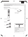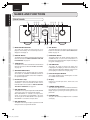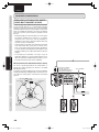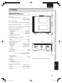
1
Model PM-11S2 User Guide
Integrated Amplifier
CAUTION
RISK OF ELECTRIC SHOCK DO NOT OPEN
CAUTION: TO REDUCE THE RISK OF ELECTRIC SHOCK,
DO NOT REMOVE COVER (OR BACK) NO USER-SERVICEABLE
PARTS INSIDE REFER SERVICING TO QUALIFIED
SERVICE PERSONNEL
The lightning flash with arrowhead symbol within an equilateral triangle is intended to alert the user to the presence
of uninsulated “dangerous voltage” within the product’s enclosure that may be of sufficient magnitude to constitute a
risk of electric shock to persons.
The exclamation point within an equilateral triangle is intended to alert the user to the presence of important
operating and maintenance (servicing) instructions in the literature accompanying the product.
WARNING
TO REDUCE THE RISK OF FIRE OR ELECTRIC SHOCK, DO NOT EXPOSE THIS APPLIANCE TO
RAIN OR MOISTURE.
CAUTION:
TO PREVENT ELECTRIC SHOCK, MATCH WIDE BLADE OF PLUG TO WIDE SLOT, FULLY
INSERT.
ATTENTION: POUR EVITER LES CHOCS ELECTRIQUES, INTRODUIRE LA LAME LA PLUS LARGE DE LA
FICHE DANS LA BORNE CORRESPON-DANTE DE LA PRISE ET POUSSER JUSQU’AU FOND.
PM-11S2_UN_00_cover etc.indd Sec1:1
08.8.7 6:49:50 PM
IMPORTANT SAFETY INSTRUCTIONS
READ BEFORE OPERATING EQUIPMENT
This product was designed and manufactured to meet strict quality and safety standards.
There are, however, some installation and operation precautions which you should be particularly aware of.
1. Read these instructions.
2. Keep these instructions.
3. Heed all warnings.
4. Follow all instructions.
5. Do not use this apparatus near water.
6. Clean only with dry cloth.
7. Do not block any ventilation openings. Install in accordance with the manufacture's instructions.
8. Do not install near any heat sources such as radiators, heat registers, stoves, or other apparatus (including amplifiers) that
produce heat.
9. Do not defeat the safety purpose of the polarized or grounding-type plug. A polarized plug has two blades with one wider
than the other. A grounding type plug has two blades and a third grounding prong. The wide blade or the third prong are
provided for your safety. If the provided plug does not fit into your outlet, consult an electrician for replacement of the
obsolete outlet.
10. Protect the power cord from being walked on or pinched particularly at plugs, convenience receptacles, and the point where
they exit from the apparatus.
11. Only use attachments/accessories specified by the manufacturer.
12. Use only with the cart, stand, tripod, bracket, or table specified by the manufacturer, or sold with the apparatus. When a cart
is used, use caution when moving the cart/apparatus combination to avoid injury from tip-over.
13. Unplug this apparatus during lightning storms or when unused for long periods of time.
14. Refer all servicing to qualified service personnel. Servicing is required when the apparatus has been damaged in any
way, such as power-supply cord or plug is damaged, liquid has been spilled or objects have fallen into the apparatus, the
apparatus has been exposed to rain or moisture, does not operate normally, or has been dropped.
Additional Safety Information!
• This product should not be placed in a built-in installation such as a bookcase or rack unless proper ventilation is provided or
the manufacturer’s instructions have been adhered to.
• Apparatus shall not be exposed to dripping or splashing and that no objects filled with liquids, such as vases, shall be placed
on the apparatus.
• When the switch is in the OFF position, the apparatus isn’t completely switched-off from the MAINS.
• The equipment shall be installed near the power supply so that the power supply is easily accessible.
• Do not touch hot areas, especially around the “hot surface mark” during and immediately after use.
• During and immediately after use, this product is hot in areas other than the controls and rear panel connection jacks. Do not
touch hot areas, especially around the “hot surface mark” and the top panel. Contact with hot areas can cause burns.
Hot surface mark
• Do not expose the unit and batteries to excessive heat such as direct sunlight, fire or the like.
• Make a space of about 8 inchs (0.2 m) around the unit.
PM-11S2_UN_00_cover etc.indd Sec1:2
AMP_080708U2
08.8.7 6:49:51 PM
ENGLISH
WARRANTY
For warranty information, contact your local Marantz distributor.
RETAIN YOUR PURCHASE RECEIPT
Your purchase receipt is your permanent record of a valuable purchase.
It should be kept in a safe place to be referred to as necessary for
insurance purposes or when corresponding with Marantz.
IMPORTANT
When seeking warranty service, it is the responsibility of the consumer to
establish proof and date of purchase. Your purchase receipt or invoice is
adequate for such proof.
FOR U.K. ONLY
This undertaking is in addition to a consumer's statutory rights and
does not affect those rights in any way.
NEDERLANDS
GARANTIE
Voor inlichtingen omtrent garantie dient u zich tot uw plaatselijke
Marantz.
UW KWITANTIE, KASSABON E.D. BEWAREN
Uw kwitantie, kassabon e.d. vormen uw bewijs van aankoop van
een waardevol artikel en dienen op een veilige plaats bewaard te
worden voor evt, verwijzing bijv, in verbend met verzekering of bij
correspondentie met Marantz.
BELANGRIJK
Bij een evt, beroep op de garantie is het de verantwoordelijkheid van de
consument een gedateerd bewijs van aankoop te tonen. Uw kassabon
of factuurzijn voldoende bewijs.
ITALIANO
FRANÇAIS
GARANTIE
Pour des informations sur la garantie, contacter le distributeur local
Marantz.
CONSERVER L'ATTESTATION D'ACHAT
L'attestation d'achat est la preuve permanente d'un achat de valeur.
La conserver en lieu sur pour s'y reporter aux fins d'obtention d'une
couverture d'assurance ou dans le cadre de correspondances avec
Marantz.
IMPORTANT
Pour l'obtention d'un service couvert par la garantie, il incombe au
client d'établir la preuve de l'achat et d'en corroborer la date. Le reçu
ou la facture constituent des preuves suffisantes.
DEUTSCH
GARANTIE
Bei Garantiefragen wenden Sie sich bitte an Ihren Marantz-Händler.
GARANZIA
L’apparecchio è coperto da una garanzia di buon funzionamento della
durata di un anno, o del periodo previsto dalla legge, a partire dalla
data di acquisto comprovata da un documento attestante il nominativo
del Rivenditore e la data di vendita. La garanzia sarà prestata con la
sostituzione o la riparazione gratuita delle parti difettose.
Non sono coperti da garanzia difetti derivanti da uso improprio, errata
installazione, manutenzione effettuata da personale non autorizzato
o, comunque, da circostanze che non possano riferirsi a difetti di
funzionamento dell’apparecchio. Sono inoltre esclusi dalla garanzia
gli interventi inerenti l’installazione e l’allacciamento agli impianti di
alimentazione.
Gli apparecchi verranno riparati presso i nostri Centri di Assistenza
Autorizzati. Le spese ed i rischi di trasporto sono a carico del cliente.
La casa costruttrice declina ogni responsabilità per danni diretti o indiretti
provocati dalla inosservanza delle prescrizioni di installazione, uso e
manutenzione dettagliate nel presente manuale o per guasti dovuti ad uso
continuato a fini professionali.
HEBEN SIE IHRE QUITTING GUT AUF
Die Quittung dient Ihnen als bleibende Unterlage für Ihren wertvollen
Einkauf Das Aufbewahren der Quittung ist wichtig, da die darin
enthaltenen Angaben für Versicherungswecke oder bei Korrespondenz
mit Marantz angeführt werden müssen.
WICHTIG!
Bei Garantiefragen muß der Kunde eine Kaufunterlage mit
Kaufdatum vorlegen. Ihren Quittung oder Rechnung ist als Unterlage
ausreichend.
PM-11S2_UN_00_cover etc.indd Sec1:3
08.8.7 6:49:51 PM
CE MARKING
English
The PM-11S2 is in conformity with the EMC directive and low-voltage directive.
Français
Le PM-11S2 est conforme à la directive EMC et à la directive sur les basses tensions.
Deutsch
Das Modell PM-11S2 entspricht den EMC-Richtlinien und den Richtlinien für Niederspannungsgeräte.
Nederlands
De PM-11S2 voldoet aan de EMC eisen en de vereisten voor laag-voltage.
Italiano
Il PM-11S2 è conforme alle direttive CEE ed a quelle per i bassi voltaggi.
English
-
-
Français
WARNINGS
Do not expose the equipment to rain, moisture, dripping or
splashing.
Do not remove the cover from the equipment.
Do not insert anything into the equipment through the ventilation
holes.
Do not handle the mains cord with wet hands.
Do not cover the ventilation with any items such as tablecloths,
newspapers, curtains, etc.
No naked flame sources, such as lighted candles, should be placed
on the equipment.
When disposing of used batteries, please comply with governmental
regulations or environmental public instruction’s rules that apply in
your country or area.
Make a space of about 0.2 meter around the unit.
No objects filled with liquids, such as vases, shall be placed on the
equipment.
When the switch is in the OFF position, the equipment is not
completely switched off from MAINS.
The equipment shall be installed near the power supply so that the
power supply is easily accessible.
- Do not touch hot areas, especially around the “hot surface mark”
during and immediately after use.
- During and immediately after use, this product is hot in areas other
than the controls and rear panel connection jacks. Do not touch hot
areas, especially around the “hot surface mark” and the top panel.
Contact with hot areas can cause burns.
AVERTISSEMENTS
- Ne pas exposer l’appareil à la pluie, à l’humidité, à l’égouttement ou
aux éclaboussures.
- Ne pas essayer de retirer le boîtier de l’appareil.
- Ne rien insérer dans l’appareil par les orifices de ventilation.
- Ne pas manipuler le cordon d’alimentation avec les mains
mouillées.
- Ne pas recouvrir les ouïes de ventilation avec un objet quelconque
comme une nappe, un journal, un rideau, etc.
- Ne placer aucune source de flamme nue, comme une bougie
allumée, sur l'appareil.
- Pour mettre au rebut les piles usées, respecter les lois
gouvernementales ou les règlements officiels concernant
l’environnement qui s'appliquent à votre pays ou région.
- Veiller à ce qu’aucun objet ne soit à moins de 0,2 mètre des côtés
de l'appareil.
- Aucun objet rempli de liquide, un vase par exemple, ne doit être
placé sur l'appareil.
- Lorsque l'interrupteur est sur la position OFF, l'appareil n'est pas
complètement déconnecté du SECTEUR (MAINS).
- L'appareil sera installé près de la source d'alimentation, de sorte que
cette dernière soit facilement accessible.
- Ne pas toucher aux zones chaudes, notamment celles se trouvant
autour du « signal zone chaude » pendant et immédiatement après
l’utilisation.
- Pendant l’utilisation et immédiatement après, cet appareil est chaud
en dehors des commandes et des prises de raccordement arrière.
Ne pas toucher aux zones chaudes, notamment celles se trouvant
autour du « signal zone chaude » et le panneau supérieur, pour
éviter tout risque de brûlure.
Hot surface mark
- Do not expose the unit and batteries to excessive heat such as direct
sunlight, fire or the like.
Signal zone chaude
- N'exposez pas l'appareil et les piles à une chaleur excessive,
comme par exemple aux rayons directs du soleil, au feu, etc.
PM-11S2_UN_00_cover etc.indd Sec1:4
08.8.7 6:49:51 PM
Deutsch
-
Italiano
WARNHINWEISE
Das Gerät nicht Regen, Feuchtigkeit, Tropf- oder Spritzwasser
aussetzen.
Die Abdeckung nicht vom Gerät abnehmen.
Keine Gegenstände durch die Belüftungsschlitze stecken.
Das Netzkabel nicht mit feuchten oder nassen Händen anfassen.
Decken Sie die Lüftungsöffnungen nicht mit einem Tischtuch, einer
Zeitung, einem Vorhang usw. ab.
Es dürfen keine Gegenstände mit offener Flamme, wie etwa
brennende Kerzen, auf dem Gerät aufgestellt werden.
Beachten Sie bei der Entsorgung der verbrauchten Batterien alle
geltenden lokalen und überregionalen Regelungen.
Auf allen Geräteseiten muß ein Zwischenraum von ungefähr 0,2
meter vorhanden sein.
Auf das Gerät dürfen keine mit Flüssigkeiten gefüllte Behälter, wie
etwa eine Vase, gestellt werden.
Wenn der Schalter ausgeschaltet ist (OFF-Position), ist das Gerät
nicht vollständig vom Stromnetz (MAINS) abgetrennt.
Das Gerät sollte in der Nähe einer Netzsteckdose aufgestellt
werden, damit es leicht an das Stromnetz angeschlossen werden
kann.
- Berühren Sie während oder unmittelbar nach dem Gebrauch keine
heißen Stellen des Gerätes, insbesondere nicht im Bereich des
Warnsymbols "Vorsicht, heiße Oberfläche".
- Während oder unmittelbar nach dem Gebrauch ist dieses Gerät mit
Ausnahme der Bedienelemente und der Anschlussbuchsen auf der
Rückseite heiß. Berühren Sie die heißen Stellen und insbesondere
den Bereich um das Warnsymbol “Vorsicht, heiße Oberfläche” nicht.
Der Kontakt mit heißen Flächen kann zu Verbrennungen führen.
Warnsymbol “Vorsicht,
heiße Oberfläche”
- Setzen Sie das Gerät und die Batterien keiner übermäßigen Wärme
aus, z.B. durch Aufstellung in direkter Sonneneinstrahlung, in der
Nähe eines offenen Feuers usw.
AVVERTENZE
- Non esporre l’apparecchio alla pioggia, all’umidità, al gocciolamento
o agli spruzzi.
- Non rimuovere il coperchio dell’apparecchio.
- Non introdurre oggetti all’interno dell’apparecchio attraverso i fori di
ventilazione.
- Non toccare il cavo di alimentazione con le mani bagnate.
- Non coprire le fessure di ventilazione con tovaglie, giornali, tende od
oggetti analoghi.
- Non posare sull'apparecchio sorgenti di fiamme scoperte quali
candele accese.
- Smaltire le pile usate in conformità alle norme governative o
disposizioni ambientali vigenti nel proprio paese o zona.
- Lasciare 0,2 metro liberi tutto intorno l'unità.
- Non mettere sull'apparecchiatura alcun contenitore di liquido, come
ad esempio dei vasi.
- Quando l'interruttore è nella posizione OFF, l'apparecchiatura non è
completamente scollegata da MAINS.
- L’apparecchio va installato in prossimità della fonte di alimentazione,
in modo che quest’ultima sia facilmente accessibile.
- Non toccare le parti calde, né durante, soprattutto se contrassegnate
dal “simbolo di superficie calda”, né immediatamente dopo l'uso.
- Durante, e subito dopo l’utilizzo, l’unità risulta essere molto calda
in alcune sue parti come ad esempio I connettori del pannello
posteriore. Non toccare le parti calde, soprattutto se contrassegnate
dal “simbolo di superficie calda” e specialmente la superficie del
pannello. Il contatto con parti calde può provocare ustioni.
Simbolo di
superficie calda
- Non esporre l'unità e le batterie a calore eccessivo come la luce
diretta del sole, il fuoco o così via.
Nederlands
-
-
WAARSCHUWINGEN
Stel het apparaat niet bloot aan regen, vocht, druppels of spetters.
Verwijder de afdekplaat van het apparaat niet.
Duw niets door de ventilatieopeningen in het apparaat.
Raak het netsnoer niet met natte handen aan.
Bedek de ventilatieopeningen niet met enige voorwerpen, zoals
tafelkleden, kranten, gordijnen, enz.
Plaats geen brandende voorwerpen, zoals kaarsen, op het
apparaat.
Volg bij het weggooien van verbruikte batterijen de overheidswetgeving
of milieuvoorschriften op die van kracht zijn in het land of de regio
waarin u zich bevindt.
Zorg dat er 0,2 meter vrije ruimte rond het toestel is.
Plaats geen voorwerpen met een vloeistof erin, zoals een
bloemenvaas, op het apparaat.
Als de schakelaar op OFF staat, is het apparaat niet volledig
losgekoppeld van de netspanning (MAINS).
De apparatuur wordt in de buurt van het stopcontact geïnstalleerd,
zodat dit altijd gemakkelijk toegankelijk is.
- Raak hete gedeelten van het apparaat, vooral rond de “markering
warm oppervlak”, niet aan tijdens en onmiddellijk na het gebruik.
- Tijdens en onmiddellijk na het gebruik is dit apparaat heet, behalve
in de omgeving van de bedieningstoetsen en de aansluitingen op
het achterpaneel. Raak hete gedeelten van het apparaat, vooral
rond de "markering warm oppervlak" en het bovenpaneel, niet aan.
Contact met hete plekken kan brandwonden veroorzaken.
Markering warm
oppervlak
- Stel het apparaat en de batterijen niet bloot aan grote warmte, zoals
direct zonlicht, vuur en dergelijke.
PM-11S2_UN_00_cover etc.indd Sec1:5
AMP_080708N1
08.8.7 6:49:51 PM
Thank you for selecting the Marantz PM-11S2 Integrated amplifier for your Audio system.
Please read these operating instructions carefully. We recommend that you read the entire user guide before
you attempt to connect or operate the player.
After you have reviewed the contents of this manual, we suggest that you make all system connections before
you attempt to operate the unit.
7 Checking the accessories
NAMES AND FUNCTIONS
ENGLISH
• Remote controller
BASIC CONNECTIONS
After opening the cover of the packing box, check that the following accessories are included.
• User Guide
OPEN/
CLOSE
SOUND
MODE
PHONO
BALANCED
CD
RECORDER 1
LINE 1
RECORDER 2
LINE 2
TRIM
EXIT
TONE
+
L
R
DISPLAY
-
ATT
BASIC OPERATIONS
ENTER
• Warranty Card (U.S.A)
(U.S.A. x 1, Canada x 1)
RANDOM
SCAN
REPEAT
TOP MENU
RETURN
MENU
AM/A
FM/B
ADVANCED CONNECTIONS
VOLUME
ADVANCED OPERATIONS
• Size “AAA” batteries x 2
• AC Power cord
PM-11S2 (U.S.A.)
TROUBLESHOOTING
A NOTE ABOUT RECYCLING
PM-11S2 (Europe)
OTHERS
This product’s packaging materials are recyclable
and can be reused. This product and the accessories
packed together are the applicable product to the WEEE
directive except batteries.
Please dispose of any materials in accordance with your
local recycling regulations.
When discarding the unit, comply with your local rules
or regulations.
Batteries should never be thrown away or incinerated
but disposed of in accordance with your local regulations
concerning chemical wastes.
1
PM-11S2_UN_01_Eng.indd 1
08.8.7 6:42:16 PM
ENGLISH
NAMES AND FUNCTIONS
CONTENTS
FEATURES ..................................................................................................................3
BEFORE USING ..........................................................................................................4
EQUIPMENT MAINS WORKING SETTING.......................................................................................4
COPYRIGHT ......................................................................................................................................4
BASIC CONNECTIONS
INAPPROPRIATE PLACES FOR INSTALLATION .............................................................................4
USAGE OF REMOTE CONTROLLER ...............................................................................................5
NAMES AND FUNCTIONS .........................................................................................6
FRONT PANEL...................................................................................................................................6
DISPLAY ............................................................................................................................................7
BASIC OPERATIONS
REMOTE CONTROLLER ..................................................................................................................8
REAR PANEL .....................................................................................................................................9
BASIC CONNECTIONS ............................................................................................10
CONNECTING AUDIO COMPONENTS ..........................................................................................10
BALANCED JACKS .........................................................................................................................11
ADVANCED CONNECTIONS
CONNECTING SPEAKER SYSTEMS .............................................................................................12
WIRING SPEAKER CABLE .............................................................................................................13
CONNECTING OF AC POWER CABLE ..........................................................................................13
BASIC OPERATIONS ...............................................................................................14
PLAYBACK .......................................................................................................................................14
ADVANCED OPERATIONS
REMOTE CONTROL OPERATION ..................................................................................................15
ADVANCED CONNECTIONS....................................................................................16
BI-WIRING CONNECTION ..............................................................................................................16
STEREO COMPLETE BI-AMP CONNECTION ..............................................................................17
SPEAKER POSITIONING FOR SUPER AUDIO MULTI-CHANNEL SOUND ..................................18
BASIC CONNECTION FOR 5.1 MULTI-CHANNEL PLAYBACK .....................................................19
TROUBLESHOOTING
F.C.B.S. ............................................................................................................................................20
ADVANCED OPERATIONS.......................................................................................21
HOW TO SET ID NUMBERS ..........................................................................................................21
BI-AMP MODE .................................................................................................................................21
TRIMMING .......................................................................................................................................22
ATT. (ATTENUATION) ......................................................................................................................24
OTHERS
HOW TO OPERATE THE SIDE ILLUMINATION .............................................................................24
TROUBLESHOOTING ...............................................................................................25
OTHERS ....................................................................................................................27
SPECIFICATIONS & DIMENSIONAL DRAWINGS ..........................................................................27
2
PM-11S2_UN_01_Eng.indd 2
08.8.7 6:42:17 PM
ENGLISH
DISPLAY
NAMES AND FUNCTIONS
FEATURES
ATT.
TONE
PRE OUT
OPERATE
SPEAKER
A
REC OUT
INPUT
SELECTOR
VOLUME
Input Amplifier Section
¶
Constant Current Feedback Phono Equalizer
The Constant Current Feedback Phono Equalizer of the highergrade SC-11S1 model is also provided with this model.
This equalizer, developed by Marantz, has the advantages of
both NF-type and CR-type phono equalizers, and it supports
both MM and MC cartridges.
¶
Current Feedback Balance Buffer Amplifier
The Current Feedback Balance Buffer Amplifier, which
incorporates the HDAM®SA3 amp module, is provided with
this unit, in order to faithfully convey signals from Super Audio
CD players and D/A converters that have high-quality balanced
output.
¶
Dedicated Input Buffers for All Line Input
Jacks
Each CD, LINE 1, LINE 2, RECORDER 1, and RECORDER 2
input jack has its own input buffer amplifier that incorporates an
HDAM®SA3. Those buffer amplifiers prevent mutual interference
among input sources, for faithful transmission of signals from
input sources.
Preamplifier Section
¶
Linear Control Volume
The Linear Control Volume based on the design concept for
the SC-7S2 is incorporated. For better S/N ratio, the WM8816
from Wolfson and the HDAM®SA3 have been combined, which
enables smooth adjustment in the range of 0 to -100 dB in units
of ±0.5 dB.
Power Amplifier Section
¶
Dual-Amplifier Structure
Following the design concept of the MA-9S2, this unit was
developed with the dual structure of a voltage amplifier and
power buffer amplifier. This dual structure enables the power
buffer amplifier to drive the speakers powerfully, preventing
influence from the back electromagnetic force from the speakers.
The voltage amplifier drives the power buffer with superlow
distortion.
Power Circuit
¶
Choke Input Power Supply Circuit
This unit incorporates a choke input power circuit that uses
a large-capacity smoothing capacitor, in order to thoroughly
eliminate high-frequency noise from the rectifier circuit and
external sources. The choke input power circuit supplies clean
power to the input amplifier and preamplifier sections.
Functions
¶
BI-AMP Mode
Complete bi-amp connection proposed by Marantz enables a
level of reproduction of the acoustic field never before achieved.
That complete bi-amp connection is available with the PM-11S2.
Synchronized operation of two PM-11S2 units is made possible
by F.C.B.S. connection, with each PM-11S2 in Bi-Amp mode
working as a monaural integrated amplifier.
¶
F.C.B.S.
A Floating Control Bus System (F.C.B.S.) enables the user
to connect up to four PM-11S2 units, making a diversity of
applications possible with complete bi-amp and multichannel
connections. Moreover, a ground loop is not formed among
multiple PM-11S2 units connected; therefore, sound quality is
not adversely affected.
¶
BASIC OPERATIONS
The latest HDAM®SA3, featured in the higher-grade SC-11S1/
SM-11S1, is provided with this model. Compared with the
previous HDAM®SA2, the HDAM®SA3 has further improved
temperature stability and substantially higher-speed processing.
The HDAM®SA3 is incorporated into many components, such
as the current feedback phono equalizer, balance buffer, and
input buffer.
The electronic tone control amplifier is provided for adjustment
of bass (low frequency) and treble (high frequency) sound in
units of 2 dB in the range of -8 to +8 dB. Adjustment can be
separately performed for the L and R channels, using the remote
control unit.
ADVANCED CONNECTIONS
HDAM®SA3
Tone Control Amplifier
ADVANCED OPERATIONS
¶
¶
TROUBLESHOOTING
This is an integrated amplifier based on the SC-7S2/MA-9S2
flagship models from Marantz, using leading-edge technologies
developed for the higher-grade SC-11S1/SM-11S1 models.
PHONO
MC
OTHERS
PHONES
BASIC CONNECTIONS
POWER ON/OFF
SPEAKER
B
Display
This unit adopts an LCD (Liquid Crystal Display) to display the
input source and volume level. Compared with other types of
display panels, an LCD requires less drive power and generates
less radiation noise, which minimizes any adverse effect on
sound quality.
3
PM-11S2_UN_01_Eng.indd 3
08.8.7 6:42:17 PM
ENGLISH
NAMES AND FUNCTIONS
BEFORE USING
This section must be read before any connection is made to
the mains supply.
BASIC CONNECTIONS
EQUIPMENT MAINS WORKING
SETTING
Your Marantz product has been prepared to comply with the
household power and safety requirements that exist in your area.
— Power requirements (U.S.A.) ....................AC 120V 60Hz
— Power requirements (Europe) ..............AC 230V 50/60Hz
COPYRIGHT
BASIC OPERATIONS
Recording and playback of any material may require consent.
For further information refer to the following:
— Copyright Act 1956
INAPPROPRIATE PLACES FOR
INSTALLATION
To keep your amplifier in perfect working order for the longest
possible time, avoid installing the unit in the following locations.
• Wherever it will be exposed to direct sunlight
• Wherever it will be close to a heater or other heat-radiating
appliance
• Wherever the humidity is high or ventilation is poor
• Wherever it is very dusty
• Wherever it will be subject to vibration
• On top of a rickety stand or in an unstable location which is
tilted at an angle
• In an audio rack with little space at the top and bottom or other
location where the heat dissipation will be obstructed
To ensure proper heat dissipation, install the unit while
leaving clearances between the unit and wall or other
components, as shown in the figure below.
— Dramatic and Musical Performers Act 1958
— Performers Protection Acts 1963 and 1972
— Any subsequent statutory enactments and orders
Above 7-7/8 ins.
(0.2 m) or more
ADVANCED CONNECTIONS
Left 7-7/8 ins.
(0.2 m) or more
Right 7-7/8 ins.
(0.2 m) or more
DISPLAY
ATT.
TONE
PRE OUT
OPERATE
SPEAKER
A
REC OUT
INPUT
SELECTOR
VOLUME
POWER ON/OFF
SPEAKER
B
PHONES
PHONO
MC
ADVANCED OPERATIONS
Rear 7-7/8 ins.
(0.2 m) or more
TROUBLESHOOTING
7 Do not place objects on top
• Refrain from placing any objects on top of the unit.
7 Cautions on handling power cord
OTHERS
• Do not touch the power cord with wet hands.
• When disconnecting the power cord, always make sure that
you take hold of the plug. Yanking out or bending the cord
can damage it and/or cause electric shocks or a fire.
• Get into the habit of disconnecting the power plug before
leaving home.
4
PM-11S2_UN_01_Eng.indd 4
08.8.7 6:42:17 PM
BEFORE USING
Operate the unit with the remote controller within the range of
the illustration below.
BASIC CONNECTIONS
Before using the remote controller for the first time, load the
batteries in the remote controller. The batteries provided are
used to verify the operations of the remote controller only.
1. Remove the battery cover.
BASIC OPERATIONS
Approx. 5m
2. Insert the batteries with correct +/– orientation.
Two AAA-size (R03) batteries
Remote controller
Precautions
3. Close the battery cover until it clicks shut.
• Do not allow direct sunlight, an inverter fluorescent light or
other strong source of light to shine onto the player’s infrared
signal reception window (remote sensor). Otherwise, the
operation of the remote control unit may be disabled.
• Bear in mind that operating the remote control unit may cause
other devices operated by infrared rays to be operated by
mistake.
• The remote control unit cannot be operated if the space
between the controller and the player’s remote sensor is
obstructed.
• Do not place any objects on top of the remote control unit.
Doing so may cause one or more buttons to be held down
which will cause the batteries to run down.
Cautions on handling batteries
OTHERS
TROUBLESHOOTING
Misuse of the batteries can result in electrolyte leakage,
rupturing, corrosion, etc.
Bear in mind the following points when using batteries.
• Remove the batteries from the remote control unit if the unit
is not going to be used for a prolonged period (a month or
more).
• Do not use an old battery together with a new one.
• Insert the batteries while ensuring that their ª and · poles
are properly aligned with the corresponding markings on the
remote control unit.
• Batteries with the same shape may have different voltages.
Do not use different types of batteries together.
• If electrolyte has leaked, thoroughly wipe the inside of the
battery compartment, and then insert new batteries.
• When batteries which are no longer required are to be
discarded, follow the directions (regulations) laid down by the
local authorities in the area concerned for their disposal.
ADVANCED CONNECTIONS
7 Loading batteries
7 Operational range
ADVANCED OPERATIONS
USAGE OF REMOTE CONTROLLER
NAMES AND FUNCTIONS
ENGLISH
5
PM-11S2_UN_01_Eng.indd 5
08.8.7 6:42:18 PM
ENGLISH
NAMES AND FUNCTIONS
NAMES AND FUNCTIONS
FRONT PANEL
q
wer
t
y ui
o
BASIC CONNECTIONS
DISPLAY
ATT.
TONE
PRE OUT
!0
OPERATE
SPEAKER
A
REC OUT
INPUT
SELECTOR
VOLUME
POWER ON/OFF
SPEAKER
B
PHONES
BASIC OPERATIONS
!4
q INPUT SELECTOR Knob
ADVANCED CONNECTIONS
This knob is for selecting the input source to use in
playback and recording. The selected input source is
displayed in the display !2.
w DISPLAY Button
This button turns the display and side illumination ON and
OFF. For instructions on HOW TO OPERATE THE SIDE
ILLUMINATION, see page. 24.
PHONO
MC
!3 !2
!1
i ATT. Button
This button attenuates the volume with one press of the
button. For instructions on How to Set the Attenuation
Level, see page. 24.
o PHONO MC Button
This button switches the phono equalizer between MC
and MM. When MC is set, the center of the button is lit a
blue color. Set the phono equalizer amplifier according to
the type of cartridge you use.
e TONE Button
ADVANCED OPERATIONS
This button turns the bass and treble tone control ON and
OFF. For instructions on How to Trim Bass and Treble,
see page. 23.
r SPEAKER A/B Buttons
These buttons turn the speaker output to the speakers
connected to the SPEAKER SYSTEM A/B terminals on
the rear panel ON and OFF. To listen with headphones,
turn speaker output OFF.
TROUBLESHOOTING
t Illumination Lamp
The illumination lamp casts a blue light over the switches
and buttons. It can be turned ON and OFF with the
DISPLAY button. For instructions on HOW TO OPERATE
THE SIDE ILLUMINATION, see page. 24.
y REC OUT Button
OTHERS
This button turns the signals output from the RECORDER
1 and 2 OUT jacks on the rear panel ON and OFF.
When RECORDER 1 is selected as the input source,
signals are not output to the RECORDER 1 OUT jack.
The same goes for the RECORDER 2 OUT jack when
RECORDER 2 is selected as the input source.
!0 VOLUME Knob
This knob is for setting the volume. The volume level
is displayed on the display !2. When turned slowly, the
volume can be fine-adjusted in 0.5dB steps, whereas when
turned rapidly, the volume level changes greatly.
!1 Infrared Receptor Window
This receptor window receives control signals sent from
the included remote controller.
!2 Display
Indicate the selected input source, volume level, and
setting status.
!3 POWER ON/OFF Switch
This switch turns power to the unit ON and OFF. When
pressed, power is activated and the blue indicator in the
display !2 lights up. Pressing the switch again turns the
power OFF.
!4 PHONES Jack
This jack is for connecting headphones with a standard
stereo plug.
u PRE OUT Button
This button is for turning the output signal from the PRE
OUT jacks on the rear panel ON and OFF.
6
PM-11S2_UN_01_Eng.indd 6
08.8.7 6:42:18 PM
ENGLISH
VOLUME Indicator Volume Display
Max
!5
Turn the VOLUME knob on the
unit to the right, or press the
VOLUME 5 button on the remote
controller.
!6
OPERATE
!7
BASIC CONNECTIONS
DISPLAY
NAMES AND FUNCTIONS
NAMES AND FUNCTIONS
!6 Display Panel
Approximately 3 seconds after the power to the unit is
activated, the ID number is displayed here.
After that, the top line displays the selected input source,
and the bottom line displays the volume level. The volume
attenuation (dB units) is displayed.
Min
The display also displays the setting values when adjusting
the left-right level balance. For instructions on How to
Trim Volume Level, see page. 22. Other messages that
correspond to various operations are also displayed.
!7 OPERATE Indicator
OTHERS
This indicator flashes the operating status of the unit.
When the ID is set to “0” for standalone operation, it is lit
a red color. When multiple amplifiers are connected by
F.C.B.S., only ID number “1” for the master is lit red color.
The slave amplifier whose indicator does not light a red
color cannot be used to operate other units in sync.
For more information on F.C.B.S., see page. 20.
The indicator flashes red if a protective circuit trips.
ADVANCED CONNECTIONS
Turn the VOLUME knob on the
unit to the left, or press the
VOLUME ∞ button on the remote
controller.
ADVANCED OPERATIONS
This indicator is lit a blue color while power to the unit is
ON.
TROUBLESHOOTING
!5 Power Indicator
BASIC OPERATIONS
0.5dB Steps
7
PM-11S2_UN_01_Eng.indd 7
08.8.7 6:42:18 PM
ENGLISH
NAMES AND FUNCTIONS
NAMES AND FUNCTIONS
REMOTE CONTROLLER
BASIC CONNECTIONS
This remote controller can be used to control the PM-11S2 and
Marantz Super Audio CD players or DVD players that have a
remote control receptor. The operations possible by remote
control may differ with each component, therefore see the
instruction manual that came with the component.
OPEN/
CLOSE
SOUND
MODE
z Input Selector Buttons
These buttons are for selecting the input source to use
in playback.
x TRIM Button
This button starts the various trim adjustments.
(Page. 22)
When multiple units are connected by F.C.B.S., this button
selects the unit with which to perform trimming.
c EXIT Button
This button ends the trimming mode when trimming is
finished.
PHONO
BALANCED
CD
BASIC OPERATIONS
RECORDER 1
LINE 1
RECORDER 2
LINE 2
TRIM
EXIT
v TONE Button
This button turns tone (bass /treble) control ON and
OFF.
TONE
b ATT Button
+
L
R
This button attenuates volume level with one press.
(page. 24)
ENTER
ADVANCED CONNECTIONS
n Volume Buttons
DISPLAY
-
ATT
3 : This button increases the volume level.
4 : This button decreases the volume level.
m DISPLAY Button
VOLUME
This button turns the display ON and OFF.
, Cursor Buttons
ADVANCED OPERATIONS
RANDOM
SCAN
REPEAT
TOP MENU
RETURN
MENU
AM/A
FM/B
TROUBLESHOOTING
In the Trimming Mode
These buttons are for selecting the channel to trim and
the trimming level.
ENTER : This button selects the trim mode
(LEVEL/BASS/TREBLE).
2 / R : This button selects the R channel for
trimming.
1/L
: This button selects the L channel for trimming.
3 / + : This button increases the trimming level.
4/–
: This button decreases the trimming level.
Other than the Trimming Mode
2, 1, 3, 4 and ENTER: These buttons are for selecting
settings items on menu displays of Marantz DVD players,
etc. For operations of supported Marantz products, see
the tables on the 15 page and the instruction manual of
the Marantz component.
. Component Operating Buttons
OTHERS
These buttons are for operating Marantz Super Audio CD
players, DVD players, etc. For operations of supported
Marantz products, see the tables on the 15 page and the
instruction manual of the Marantz component.
8
PM-11S2_UN_01_Eng.indd 8
08.8.7 6:42:18 PM
ENGLISH
NAMES AND FUNCTIONS
NAMES AND FUNCTIONS
REAR PANEL
!2
AC IN
3
1
2
1
!1
q LINE 1/2 Input Jacks
These jacks are for connecting to the output jacks of a
tuner, DVD player, etc.
w CD Input Jacks
These jacks are for connecting to the output jacks of a
Super Audio CD player, etc.
e PHONO GND Terminal
Connect the grounding wire from an analog record player
here.
r PHONO Input Jacks
These jacks are for connecting to an analog record player.
Both MC and MM cartridges can be used, therefore set
the PHONO MC button on the front panel according to the
type of cartridge you are using.
t BALANCED Jacks
These jacks are for connecting to the balanced output
jacks of a Super Audio CD player, etc.
y PRE OUT Jacks
!0
o
BASIC OPERATIONS
3
2
u
BASIC CONNECTIONS
y
i
i AC IN Power Cable Connection Socket
Connect this socket to the power outlet using the included
power cord.
o F.C.B.S. IN/OUT Jacks
These jacks are used to connect and synchronize up to
four amplifiers. For instructions on use and connections,
see F.C.B.S. (page. 20).
!0 SPEAKER SYSTEMS Output Terminals
You can connect 2 speaker systems to the PM-11S2.
Speaker output can be turned ON/OFF from the SPEAKER
A and B buttons on the front panel.
!1 RECORDER 1/2 Output Jacks
These jacks are for connecting to the recording input jacks
of a tape deck etc.
Output signals can be turned ON/OFF from the REC OUT
button on the front panel.
!2 RECORDER 1/2 Input Jacks
These jacks are for connecting to the output jacks of a
tape deck or other type of recording device.
These jacks are for connecting to the input jacks of another
main amplifier or active subwoofer. Output signals can be
turned ON/OFF from the PRE OUT button on the front
panel.
OTHERS
u AMP MODE Switch
ADVANCED CONNECTIONS
t
ADVANCED OPERATIONS
r
TROUBLESHOOTING
qw e
STEREO: Set to use this unit as a normal two-channel
stereo amplifier.
BI-AMP: Set to use this unit in complete bi-amp
connection.
For more information on BI-AMP MODE, see page. 21.
9
PM-11S2_UN_01_Eng.indd 9
08.8.7 6:42:19 PM
ENGLISH
NAMES AND FUNCTIONS
BASIC CONNECTIONS
CONNECTING AUDIO COMPONENTS
CD player, etc.
Record player
To BALANCED LINE OUT jack
SUPER AUDIO CD PLAYER SA-11S1
OPEN/
CLOSE
PLAY
BASIC CONNECTIONS
STOP
DISPLAY OFF
SOUND
MODE
CD Player
POWER ON/OFF
PAUSE
To LINE OUT jack
SUPER AUDIO CD PLAYER SA-11S1
OPEN/
CLOSE
PLAY
BASIC OPERATIONS
STOP
DISPLAY OFF
SOUND
MODE
POWER ON/OFF
PAUSE
3
2
2
1
To LINE OUT jack
Tuner, etc.
ADVANCED CONNECTIONS
DVD Player, etc.
DVD PLAYER DV-12S1
VIDEO ON/OFF
DIMMER
3
1
OPEN/CLOSE
PLAY
To LINE OUT jack
STOP
PAUSE
RANDOM
V-PART
GRP
TITLE
POWER
DVD
AUDIO
192kHz
96kHz TRK
DIG OFF CHP
STANDBY
LAST MEMO
CONDITION
DOWN MIX
PROGRESSIVE
DOLBY D
TEMAIN
TOTAL VIDEO OFF
L
LS
C R
LFE
S RS
FL OFF
ADVANCED OPERATIONS
To LINE OUT jack
CD-R, etc.
To LINE IN jack
TROUBLESHOOTING
To LINE OUT jack
Tape deck, etc.
To LINE IN jack
OTHERS
10
PM-11S2_UN_01_Eng.indd 10
08.8.7 6:42:19 PM
• Insert the plugs of the connections cords firmly into the
connecting jacks. Incorrect insertion may cause noise.
• Connect the wires correctly to the L (left) and R (right)
channels. The red jack is the R (right) channel, and the
white jack is the L (left) channel.
• Make sure that input and output are connected correctly.
• Refer also to the instruction manuals of components to
connect equipment correctly.
BALANCED JACKS
q The BALANCED jacks on this unit are equipped with XLR
connectors that are widely used on professional equipment.
Their features are listed below.
• The 3 pin construction enables the musical signal to be
transmitted as a balanced signal, with little effect from
external noise
• The detachable locking mechanism minimizes connector
play and enhances connection reliability.
w The XLR connector for professional use is internally wired
in either of the following two systems.
COLD
2
1
BASIC OPERATIONS
1. USA system (Pin w = COLD, Pin e = HOT)
GND
3
HOT
2. European system (Pin w = HOT, Pin e = COLD)
HOT
2
1
GND
3
COLD
e This unit uses the 1. USA system.
If a product that employs the European system is connected
with this unit via a balanced cable, the reproduced signal
may be phase-inverted.
OTHERS
TROUBLESHOOTING
In this case, refer to “ANALOG OUTPUT CONNECTOR
PHASE SWITCHING”, and set so that the correct phase
is used.
ADVANCED CONNECTIONS
• Do not connect the power cord of this unit or any of the
other components to the power supply until all of the
connections are completed.
ADVANCED OPERATIONS
Notes:
BASIC CONNECTIONS
BASIC CONNECTIONS
NAMES AND FUNCTIONS
ENGLISH
11
PM-11S2_UN_01_Eng.indd 11
08.8.7 6:42:19 PM
ENGLISH
NAMES AND FUNCTIONS
BASIC CONNECTIONS
CONNECTING SPEAKER SYSTEMS
BASIC CONNECTIONS
• If using an active subwoofer, set the PRE OUT button on the front panel to ON.
• Your speaker system needs to meet the following requirements. If speakers that do not meet the following requirements are used,
the amplifier protective circuit may trip, and sounds will not playback correctly. In certain cases, damage may also be caused to
the amplifier and speaker system.
• If using 1 set of speakers, total speaker impedance must be 4Ω or more.
• If using 2 sets of speakers, total speaker impedance must be 8Ω or more.
Set to “STEREO”
BASIC OPERATIONS
3
2
AC IN
3
1
2
1
ADVANCED CONNECTIONS
ADVANCED OPERATIONS
TROUBLESHOOTING
To LINE IN jacks
Active subwoofer, etc.
L CH speaker
R CH speaker
OTHERS
12
PM-11S2_UN_01_Eng.indd 12
08.8.7 6:42:19 PM
BASIC CONNECTIONS
• Peel off the coating of speaker cable as shown below.
1. Plug the supplied AC power cable to the AC IN socket on
Peel off the edge
of cable.
BASIC CONNECTIONS
the rear panel of the main unit.
Approx. 1 cm
Cut the coating
of cable.
CONNECTING OF AC POWER CABLE
Twist conductors.
AC IN
Insert conductor
of cable.
Turn clockwise to
tighten.
• Wiring with “Y” style terminal
Turn counterclockwise to loosen.
Insert conductor.
2. Plug the power cable into an AC outlet.
Connect the player so that the power cord can be
removed easily as a precaution against possible
accidents.
Turn clockwise to
tighten.
ADVANCED OPERATIONS
Turn counterclockwise to loosen.
BASIC OPERATIONS
• Wiring with speaker cable.
ADVANCED CONNECTIONS
WIRING SPEAKER CABLE
NAMES AND FUNCTIONS
ENGLISH
Notes:
TROUBLESHOOTING
• To prevent damage to circuitry, do not let the bare speaker
wires touch each other and do not let them touch any metal
part of this unit.
• Do not touch the speaker terminals when the power is on.
It may cause you to receive an electric shocks.
OTHERS
• Be sure to connect the positive and negative cables for
the speaker properly. If they are miss-connected, the
signal phase will be reversed and the signal quality will
be corrupted.
13
PM-11S2_UN_01_Eng.indd 13
08.8.7 6:42:19 PM
ENGLISH
NAMES AND FUNCTIONS
BASIC OPERATIONS
PLAYBACK
To explain how to play back input sources, representative
examples are given with an Super Audio CD player and analog
record player. Before starting either procedure, check the
component is correctly connected to the PM-11S2.
BASIC CONNECTIONS
7 Disc Playback on an Super Audio CD
Player
1. Press the power ON/OFF switch of the Super Audio CD
player to activate power to it.
2. Press the POWER ON/OFF switch !3 of the PM-11S2
6. Adjust the volume level from the VOLUME knob !0 on the
PM-11S2 or the VOLUME 3/4 buttons n of the remote
controller.
7. Adjust bass/treble as desired from the TONE button e
on the PM-11S2 or the TONE button v of the remote
controller. For instructions on how to adjust bass and treble,
see “How to Trim Bass” and “How to Trim Treble” on pg.
23.
8. You can turn the display and side illumination ON/OFF as
suited for the room environment. Press the DISPLAY button
w on the PM-11S2 or the DISPLAY button m of the remote
controller.
BASIC OPERATIONS
to activate power to it. When using multiple PM-11S2s
connected by F.C.B.S., turn power ON in the order of lowest
to highest ID number, starting from ID 1.
3. Select the input source from the INPUT SELECTOR knob
q on the PM-11S2 or the input selector buttons z of the
remote controller.
q
wer
o !0
4. To use the speakers connected to the SPEAKER A
terminals, press the SPEAKER A button r on the PM11S2.
DISPLAY
ATT.
ADVANCED CONNECTIONS
PRE OUT
TONE
5. Load a disc into the Super Audio CD player and press the
play button to start playback.
OPERATE
SPEAKER
A
REC OUT
INPUT
SELECTOR
VOLUME
POWER ON/OFF
6. Adjust the volume level from the VOLUME knob !0 on the
SPEAKER
B
PHONES
PHONO
MC
PM-11S2 or the VOLUME 3/4 buttons n of the remote
controller.
!3
7. Adjust bass/treble as desired from the TONE button e
ADVANCED OPERATIONS
on the PM-11S2 or the TONE button v of the remote
controller. For instructions on how to adjust bass and treble,
see “How to Trim Bass” and “How to Trim Treble” on pg.
23.
OPEN/
CLOSE
SOUND
MODE
PHONO
BALANCED
CD
8. You can turn the display and side illumination ON/OFF as
RECORDER 1
suited for the room environment. Press the DISPLAY button
w on the PM-11S2 or the DISPLAY button m of the remote
controller.
LINE 1
RECORDER 2
TRIM
LINE 2
EXIT
TONE
+
7 Disc Playback on an Analog Record
L
R
TROUBLESHOOTING
ENTER
Player
1. Press the POWER ON/OFF switch !3 of the PM-11S2
DISPLAY
to activate power to it. When using multiple PM-11S2s
connected by F.C.B.S., turn power ON in the order of lowest
to highest ID number, starting from ID 1.
-
ATT
VOLUME
2. Select “PHONO” as the input source from the INPUT
OTHERS
SELECTOR knob q on the PM-11S2 or the input selector
buttons z of the remote controller. To prevent unexpected
accidents, it is recommended to set the volume level to –∞
(mute) by turning the VOLUME knob !0 until muting the
volume level.
3. Set the PHONO MC button o on the PM-11S2 to MC or
RANDOM
SCAN
REPEAT
TOP MENU
RETURN
MENU
AM/A
FM/B
MM according to the cartridge you are using.
4. To use the speakers connected to the SPEAKER A
terminals, press the SPEAKER A button r on the PM11S2.
5. Set a record on the analog record player and play it.
14
PM-11S2_UN_01_Eng.indd 14
08.8.7 6:42:20 PM
PHONO
BALANCED
RECORDER 1
LINE 1
RECORDER 2
TRIM
CD
LINE 2
EXIT
TONE
+
L
R
ENTER
DISPLAY
-
ATT
Function
Open/Closes disc tray.
Selects Super Audio CD sound mode.
SOUND MODE
Selects Super Audio CD/CD.
3
Play
Track skip
4
(Returns to track beginning/previous track.)
¢
Track skip (Advances to next track.)
1
Rewind search
¡
Forward search
8
Pause
7
Stop
RANDAM
Random play
SCAN
AMS (Automatic Music Scan) play
REPEAT
Repeat play
TOP MENU/AM/A Not available for use
RETURN/FM/B
Not available for use
MENU 1 2
Sets quick replay.
ENTER
Starts quick replay.
3 /+
Not available for use
4 /–
Not available for use
1/L
Not available for use
2/R
Not available for use
VOLUME
¶
RANDOM
SCAN
REPEAT
TOP MENU
RETURN
MENU
AM/A
FM/B
Remote Controller Operation for Marantz DVD
Players
When the LINE 2 button is pressed, the buttons in groups ,
and . function as indicated in the below table. These buttons
can be used only when a Marantz DVD player is connected to
the LINE 2 input jacks.
Button
OPEN/CLOSE
SOUND MODE
3
Function
Open/Closes disc tray.
Changes sound mode.
Play
Track skip
4
(Returns to track beginning/previous track.)
¢
Track skip (Advances to next track.)
1
Rewind search
¡
Forward search
8
Pause
7
Stop
RANDAM
Random play
SCAN
Selects search mode.
REPEAT
Repeat play
TOP MENU/AM/A Displays top menu.
RETURN/FM/B
Returns to previous menu
MENU 1 2
Displays menu screen.
ENTER
Sets selected item.
3 /+
Moves cursor upward.
4 /–
Moves cursor downward.
1/L
Moves cursor to left.
2/R
Moves cursor to right.
BASIC CONNECTIONS
Button
OPEN/CLOSE
BASIC OPERATIONS
SOUND
MODE
When the CD button is pressed, the buttons in groups , and
. function as indicated in the table below. These buttons
can be used only when a Marantz Super Audio CD player is
connected to the CD input jacks.
ADVANCED CONNECTIONS
OPEN/
CLOSE
Remote Controller Operation for Marantz
Super Audio CD Players
ADVANCED OPERATIONS
The buttons in groups , and . are for operating Marantz
products other than the PM-11S2, such as Super Audio CD
players or DVD players.
The function of each button changes to match the component
selected as the input source from the INPUT SELECT buttons
z.
¶
TROUBLESHOOTING
REMOTE CONTROL OPERATION
OTHERS
BASIC OPERATIONS
NAMES AND FUNCTIONS
ENGLISH
15
PM-11S2_UN_01_Eng.indd 15
08.8.7 6:42:20 PM
ENGLISH
NAMES AND FUNCTIONS
ADVANCED CONNECTIONS
BI-WIRING CONNECTION
BASIC CONNECTIONS
A bi-wiring connection separately connects the low and mid/high jacks of the speaker to the amplifier using separate speaker
cables. Because separate cables are used for low and mid/high sounds, the return current generated in the low speaker causes
little interference with the mid/high speaker.
• If speakers that do not support bi-wiring connection are used, connect them to either the SPEAKER A or B terminals.
• If using speakers that do not support a bi-wiring connection, connect them to either the SPEAKER SYSTEM A or B terminals.
CD Player
To balanced
output jacks
SUPER AUDIO CD PLAYER SA-11S1
OPEN/
CLOSE
PLAY
STOP
DISPLAY OFF
SOUND
MODE
POWER ON/OFF
PAUSE
BASIC OPERATIONS
Set to “STEREO”.
3
2
AC IN
3
1
2
1
ADVANCED CONNECTIONS
ADVANCED OPERATIONS
TROUBLESHOOTING
OTHERS
Remove shorting bar.
MF / HF
MF / HF
LF
LF
L CH
speaker
Remove shorting bar.
R CH
speaker
Remove shorting
bar.
16
PM-11S2_UN_01_Eng.indd 16
08.8.7 6:42:20 PM
STEREO COMPLETE BI-AMP CONNECTION
q The two amplifiers are connected by F.C.B.S. for synchronized use. For F.C.B.S. connection, connect with commercially available
monaural ⇔ monaural miniplugs or stereo ⇔ stereo miniplugs as described in F.C.B.S. (page. 20).
w Set the ID numbers as explained in HOW TO SET ID NUMBERS (page. 21). When the ID1 amplifier is operated, the ID 2
amplifier will operate in sync.
e Connect the analog output of the CD player etc. to the L ch input jacks of both pre-amps.
As both pre-amps operate as monaural pre-amps in BI-AMP mode, do not use the R channel of the input jacks on these units.
¶
About Complete Bi-Amp
Proposed by Marantz, the complete bi-amp connection is an advanced technique that enhances sound quality. The low and mid/high
amplifiers are separated and independent of the preamplifier, therefore interference between low and mid/high sounds is reduced
to a minimum. As a result, a wide sound environment can be reproduced.
BASIC CONNECTIONS
ADVANCED CONNECTIONS
NAMES AND FUNCTIONS
ENGLISH
Speaker systems connected using complete bi-amp connections must support bi-amp connections. Before connecting your
speakers, check in the instruction manual that came with the speakers or contact the manufacturer to confirm whether they
support bi-amp connection.
SUPER AUDIO CD PLAYER SA-11S1
OPEN/
CLOSE
PLAY
BASIC OPERATIONS
Note:
STOP
DISPLAY OFF
POWER ON/OFF
Set PM-11S2 for L
CH to ID 1.
3
2
AC IN
3
1
2
Set SPEAKER
A button on front
panel in ON
position.
1
Set to “BI-AMP”.
Set PM-11S2 for R
CH to ID 2.
3
2
AC IN
3
1
2
1
To power outlet
Remove shorting bar.
To power
outlet
MF / HF
MF / HF
LF
LF
L CH speaker
Remove shorting bar.
ADVANCED OPERATIONS
Set to “BI-AMP”.
Remove shorting bar.
R CH speaker
OTHERS
Set SPEAKER
A button on front
panel in ON
position.
ADVANCED CONNECTIONS
PAUSE
TROUBLESHOOTING
SOUND
MODE
Remove shorting bar.
17
PM-11S2_UN_01_Eng.indd 17
08.8.7 6:42:21 PM
ENGLISH
NAMES AND FUNCTIONS
ADVANCED CONNECTIONS
SPEAKER POSITIONING FOR SUPER
AUDIO MULTI-CHANNEL SOUND
BASIC CONNECTIONS
BASIC OPERATIONS
ADVANCED CONNECTIONS
In order to enjoy Super Audio CD multi-channel sound with
the best possible acoustics, it is recommended to position
speakers as specified in ITU-R BS.775-1 of the International
Telecommunication Union (ITU). Super Audio CD multi-channel
discs are recorded and mixed so as to achieve the optimum
effect with a speaker system laid out as specified in ITU-R
BS.775-1.
• With Super Audio CD multi-channel discs, the music signals
are basically recorded using 5 channels (3 - 6 channels
sometimes), but in some cases, LFE (for subwoofer) is
recorded as a sixth channel. Each disc indicates how many
channels have been recorded on it.
• The basic layout is 3 speakers in the front and 2 in the back
since multi-channel discs usually have 5 channels. The 2
front, 1 center and 2 surround (rear) speakers should be set
in a circle around the listening point as shown below. If using
speakers of differing sizes, adjust volume balance from the
amplifier.
• The location of the subwoofer in the figure is just for
explanatory purposes. It can be located anywhere in the
room. For connection and positioning instructions, see the
instruction manual that came with the subwoofer.
¶
ITU (International Telecommunication Union)
ADVANCED OPERATIONS
The ITU is a special organization of the United Nations. It
consists of a number of organs, one of which is the Radio
Broadcasting Section.
ITU-R BS in the recommendation which consists of standards
relating to broadcasting (audio) operations, one of which is the
ITU-R BS.775-1 which governs “multi-channel stereo sound
systems.”
For front L/R speakers
Set PM-11S2 to ID 1.
Set SPEAKER A button on
front panel in ON position.
3
2
Set to “STEREO”.
AC IN
3
1
2
1
Center
speaker
Sub-woofer
Front speaker
(Right)
Front speaker
(Left)
TROUBLESHOOTING
To power outlet
60°
approx. 110°
approx. 110°
Reference listening
position
OTHERS
Rear speaker
(Left Surround)
Rear speaker
(Right Surround)
L CH
front speaker
R CH
front speaker
18
PM-11S2_UN_01_Eng.indd 18
08.8.7 6:42:21 PM
BASIC CONNECTION FOR 5.1 MULTI-CHANNEL PLAYBACK
q The three units are connected using F.C.B.S. For the F.C.B.S connection, prepare 3 audio connection cables, and refer to
F.C.B.S. on page 20.
w Set the ID numbers for the three amplifiers as explained in HOW TO SET ID NUMBERS (page. 21).
When the ID 1 unit is operated, ID 2 and ID 3 units will operate in sync.
e Connect the outputs of players that have 5.1 channel analog outputs to each of the three units.
r If using an active subwoofer, see the instruction manual that came with the subwoofer for further instructions.
MULTI CHANNEL AUDIO OUT
SURROUND R SURROUND L SUB-WOOFER
For center speaker or subwoofer
Set PM-11S2 to ID 2.
Set SPEAKER A button on front
Set to “STEREO”.
panel in ON position.
Set PRE OUT button on front
panel in ON position.
3
2
2
For surround speakers
Set PM-11S2 to ID 3.
Set SPEAKER A button on
front panel in ON position.
AC IN
3
1
CENTER
1
3
2
Set to “STEREO”.
AC IN
3
1
2
ADVANCED OPERATIONS
FRONT L
1
To power outlet
To power outlet
TROUBLESHOOTING
FRONT R
ADVANCED CONNECTIONS
BASIC OPERATIONS
SACD multi-channel player, etc.
BASIC CONNECTIONS
ADVANCED CONNECTIONS
NAMES AND FUNCTIONS
ENGLISH
OTHERS
To line input jack
Active
subwoofer
Front center
speaker
L CH
surround
speaker
R CH
surround
speaker
19
PM-11S2_UN_01_Eng.indd 19
08.8.7 6:42:21 PM
ENGLISH
NAMES AND FUNCTIONS
ADVANCED CONNECTIONS
F.C.B.S.
BASIC CONNECTIONS
F.C.B.S. (Floating Control Bus System) is a communication
system that connects up to four PM-11S2s over a dedicated
bus line so as to enable synchronized operations amongst
them via 2-way data communications.
Prepare the correct number of portable audio connection
cables for the number of units to be connected. Either of the
following types of connection cables are adequate.
¶ Monaural miniplug ⇔ monaural miniplug connecting
cable
BASIC OPERATIONS
¶ Stereo miniplug ⇔ stereo miniplug connecting cable
The figure below shows an example of four PM-11S2s
connected by F.C.B.S. The top unit is the master unit with ID
1 and controls the three slave units with ID 2~4. When the
master unit is operated, the input source, volume level, ATT
feature, display and tone control ON/OFF feature of the slave
units are operated in sync with the master unit.
This function can be applied to various usages such as
complete bi-amp with 2 PM-11S2s (page. 17), and 5.1ch multichannel with 3 PM-11S2s (page. 19).
Note:
The PM-11S2 F.C.B.S. function is only valid between the
same PM-11S2 models. This function may not operate
correctly if other Marantz models (PM-11S1, PM-15S1 etc)
are connected.
Note:
Do not use connecting cables that contain resistance.
ADVANCED CONNECTIONS
To turn the power of multiple F.C.B.S.-connected units ON/OFF, switch the power ON in order of lowest to highest ID
number, and switch the power OFF in order of highest to lowest ID number.
PM-11S2
ADVANCED OPERATIONS
ID 1 Master
PM-11S2
TROUBLESHOOTING
ID 2 Slave
PM-11S2
ID 3 Slave
OTHERS
PM-11S2
ID 4 Slave
20
PM-11S2_UN_01_Eng.indd 20
08.8.7 6:42:21 PM
If using this unit by itself as a stereo amplifier, set the ID number
to “0” (Default setting is “0”).
Note:
If the ID number is set to a number other than “0”, this unit
cannot be used for standalone operation.
The ID number of the unit appears on the display for about 3
seconds after the power is activated.
When multiple PM-11S2s are connected, a unique ID number
must be set of each one in order to distinguish between
them.
The unit that centrally controls the other units takes ID 1.
The unit with ID1 is called the “Master”. The other units that
synchronize with the master are called “slaves” and take IDs
“2” ~ “4”.
This unit is equipped with a bi-amp mode to enable a complete
bi-amp connection using two PM-11S2s. This complete
bi-amp connection is a high-end technique for enhancing
sound quality, proposed by Marantz. Using this system, the
bi-amp supporting speaker system is separated from the
preamplifiers that separately drive the low and high speakers.
(For more information, see STEREO COMPLETE BI-AMP
CONNECTION (page.17).)
The bi-amp mode is engaged by setting the operating mode
switch on the rear panel to “BI-AMP”. In the bi-amp mode, the
signals input to the L channel are split by the input selector and
sent to the left and right volume amplifiers, and are then output
to the PRE OUT terminals. The figures below show example
displays in the stereo and bi-amp modes.
Stereo mode
Bi-amp mode
INPUT SELECTOR
Knob
DISPLAY button
ATT.
Notes:
PRE OUT
TONE
OPERATE
SPEAKER
A
REC OUT
INPUT
SELECTOR
VOLUME
• When in bi-amp mode, the R channel input jacks cannot
be used.
POWER ON/OFF
PHONES
PHONO
MC
POWER ON/OFF Switch
Set ID numbers as follows.
1. While pressing and holding the DISPLAY button, press the
POWER ON/OFF switch.
• When in bi-amp mode, the signals input into the L channel
are output from both channels. Therefore, the same
signals are output from the L channel and R channel in
RECORDER OUT, PRE OUT, PHONES OUT.
• Always turn the power to the unit OFF before changing
the operating mode switch setting. Turning the power ON
again activates the new setting.
TROUBLESHOOTING
SPEAKER
B
ADVANCED OPERATIONS
DISPLAY
BASIC CONNECTIONS
BI-AMP MODE
ADVANCED CONNECTIONS
HOW TO SET ID NUMBERS
BASIC OPERATIONS
ADVANCED OPERATIONS
NAMES AND FUNCTIONS
ENGLISH
2. Turn the INPUT SELECTOR knob to the desired ID
number.
OTHERS
After finishing setting the ID number, turn power to the unit
OFF.
The setting is stored in memory and becomes active the next
time power to the unit is switched ON.
21
PM-11S2_UN_01_Eng.indd 21
08.8.7 6:42:22 PM
ENGLISH
NAMES AND FUNCTIONS
ADVANCED OPERATIONS
7 How to Trim Volume Level
TRIMMING
BASIC CONNECTIONS
There are three trimming modes.
• LEVEL trimming that adjusts the volume level on left and
right channels
• BASS trimming that adjusts the bass on left and right
channels
• TREBLE trimming that adjusts the treble on left and right
channels
The volume level of the left and right channels can be trimmed
in 0.5dB steps across a 0.0 – 9.0dB range. When the unit
is shipped from the factory, the volume level is set to 0.0dB
(maximum).
1. Press the TRIM button once to access the LEVEL trimming
mode.
Note:
Trimming is performed from the remote controller.
2. The flashing “0.0” on the left indicates that trimming is
BASIC OPERATIONS
ADVANCED CONNECTIONS
TRIM : This button starts trimming. When multiple PM-11S2s
are connected, this button selects the amplifier with
which to perform trimming. In such case, trimming
is performed in the order of the lowest to highest ID
number.
EXIT : This button ends trimming.
3 : This button increases the trimming level.
4 : This button decreases the trimming level.
2 : This button selects the R channel for trimming.
1 : This button selects the L channel for trimming.
ENTER : This button selects the trim mode (LEVEL, BASS
or TREBLE).
OPEN/
CLOSE
PHONO
BALANCED
When the right side “0.0” starts flashing, trimming is
activated for the right channel volume level. Press the 3 and
4 buttons to set the volume level of the right channel.
ADVANCED OPERATIONS
TRIM button again and set the volume level as in steps
1~3. After that, pressing the TRIM button again allows you
to trim the volume level for the “ID 3” unit and so forth.
CD
LINE 1
RECORDER 2
TRIM
3. Press the 2 button to set the right channel volume level.
4. To trim the volume level of the ID 2 (slave) unit, press the
SOUND
MODE
RECORDER 1
activated for the left channel volume level. Press the 3 and
4 buttons to set the volume level of the left channel.
LINE 2
EXIT
5. When finished with volume level trimming, press the EXIT
TONE
button.
TRIM
EXIT
+
L
R
3, 4, 2, 1
ENTER
DISPLAY
-
ATT
TROUBLESHOOTING
VOLUME
RANDOM
SCAN
REPEAT
TOP MENU
RETURN
MENU
AM/A
FM/B
OTHERS
22
PM-11S2_UN_01_Eng.indd 22
08.8.7 6:42:22 PM
1. Press the TRIM button once to access the LEVEL trimming
mode.
2. Press the ENTER button once to access the BASS trimming
mode.
mode.
2. Press the ENTER button twice to access the TREBLE
trimming mode.
3. The flashing “0” on the left indicates that trimming is
3. The flashing “0” on the left indicates that trimming is
activated for the left channel bass level. Press the 3 and
4 buttons to set the bass level of the left channel.
activated for the left channel treble level. Press the 3 and
4 buttons to set the treble level of the left channel.
4. Press the 2 button to start the “0” on the right side flashing.
4. Press the 2 button to start the “0” on the right side flashing.
When the right side “0” starts flashing, trimming is activated
for the right channel bass level. Press the 3 and 4 buttons
to set the bass level of the right channel.
When the right side “0” starts flashing, trimming is activated
for the right channel treble level. Press the 3 and 4 buttons
to set the treble level of the right channel.
5. To trim the bass level of the ID 2 (slave) unit, press the
5. To trim the treble level of the ID 2 (slave) unit, press the
TRIM button again and set the bass level as in steps 2-4.
After that, pressing the TRIM button again allows you to
trim the bass level for the “ID 3” unit and so forth.
TRIM button again and set the treble level as in steps 2-4.
After that, pressing the TRIM button again allows you to
trim the treble level for the “ID 3” unit and so forth.
6. When finished with bass level trimming, press the EXIT
6. When finished with treble level trimming, press the EXIT
button.
OTHERS
button.
BASIC CONNECTIONS
1. Press the TRIM button once to access the LEVEL trimming
BASIC OPERATIONS
The treble level of the left and right channels can be trimmed
in 2dB steps across a –8.0 – +8.0dB range. When this unit is
shipped from the factory, the bass level is set to 0 dB. To trim
the treble level, active tone control by pressing the TONE button
on either the unit or the remote controller.
ADVANCED CONNECTIONS
7 How to Trim Treble
The bass level of the left and right channels can be trimmed
in 2dB steps across a –8.0 – +8.0dB range. When this unit is
shipped from the factory, the bass level is set to 0 dB. To trim
the bass level, active tone control by pressing the TONE button
on either the unit or the remote controller.
ADVANCED OPERATIONS
7 How to Trim Bass
TROUBLESHOOTING
ADVANCED OPERATIONS
NAMES AND FUNCTIONS
ENGLISH
23
PM-11S2_UN_01_Eng.indd 23
08.8.7 6:42:22 PM
ENGLISH
NAMES AND FUNCTIONS
ADVANCED OPERATIONS
HOW TO OPERATE THE SIDE
ILLUMINATION
ATT. (ATTENUATION)
ATT. button
Illumination Lamp
DISPLAY button
DISPLAY
ATT.
BASIC CONNECTIONS
PRE OUT
TONE
DISPLAY
ATT.
OPERATE
SPEAKER
A
REC OUT
PRE OUT
TONE
INPUT
SELECTOR
VOLUME
OPERATE
POWER ON/OFF
SPEAKER
B
PHONES
PHONO
MC
SPEAKER
A
REC OUT
INPUT
SELECTOR
VOLUME
POWER ON/OFF
SPEAKER
B
ATT is a one-touch feature for reducing the volume level. When
the ATT button on either the unit or remote controller is pressed,
the volume level is attenuated.
BASIC OPERATIONS
1. When the ATT button on either the unit or the remote
controller is pressed, “ATT” flashes on the display and the
volume level is reduced.
When the ATT button is pressed again or the volume
is increased/decreased using the controls, the mode is
canceled and the original volume level is restored.
PHONES
PHONO
MC
The illumination lamp has an always-ON mode (factory setting)
and an always-OFF mode.
In the always-ON mode, the illumination lamp turns ON/OFF
in sync with the display.
1. With the illumination lamp lit, press and hold the DISPLAY
button for 3 seconds or longer. The illumination lamp goes
out, and the always-OFF mode is engaged.
ADVANCED CONNECTIONS
2. To cancel the always-OFF mode and turn the illumination
lamp ON, press and hold the DISPLAY button for 3 seconds
or longer.
2. When the ATT button is pressed with the volume level at
-∞(muted), the display will change as it is shown below
appears for about 3 seconds, and attenuation is not
applied.
ADVANCED OPERATIONS
7 How to Set Attenuation Level
Attenuation level can only be set using the ATT button on the
unit. The attenuation level can be set at –20dB, -40dB, or -∞.
The factory default setting is -20dB.
1. Press and hold the ATT button on the unit for 2 seconds or
longer. The attenuation level will appear on the display.
TROUBLESHOOTING
2. The attenuation level setting value changes with each press
of the ATT button on the unit.
3. When the desired attenuation level setting appears on the
display, leave it unchanged for 2 seconds or longer to enter
the setting. Once entered, the display returns to the volume
level indication.
OTHERS
24
PM-11S2_UN_01_Eng.indd 24
08.8.7 6:42:23 PM
Power is not supplied.
The protection circuit is activated.
Speaker connection is incomplete.
Input cable connection is incomplete.
Use of the connected player is wrong.
Power is supplied, but no sound is
heard from the speakers.
Sound is heard from the left or right
speakers only. Or, the volume from
the right and left speakers differs.
Left and r ight channels are
reversed.
Sound is monaural.
Noise occurs during record
playing.
Or, no sound is heard.
Howling occurs when sound volume
is increased during record playing.
Check the power cord connection.
If the OPERATE indicator is flashing, turn the
power OFF then back ON again after 1 minute
or more.
Check the speaker cable connection.
Check the input cable connection.
Confirm the operation methods, referring to
the instruction manual of the player.
The INPUT SELECTOR knob is not set
Set the INPUT SELECTOR knob properly.
correctly.
Turn the VOLUME knob to set the proper
The VOLUME knob is set to minimum.
level.
Set the SPEAKER A/B buttons properly,
The SPEAKER buttons are set to OFF.
according to the SPEAKER terminals to which
the speakers are connected.
If “ATT” is displayed on the display, press the
ATT. button on the main unit or remote control
The ATT. muting function is activated.
unit, or increase/decrease the volume level, in
order to cancel the attenuation function.
The protection circuit has been activated, and
Adjust the volume again.
the volume has been automatically muted.
Set the ID number properly, referring to the
An error message is displayed.
table in “ERROR MESSAGES”, on page 26.
Speaker connection is incomplete.
Check the speaker cable connection.
The set values for the volume (LEVEL
TRIM) and sound quality (BASS/TREBLE)
Perform trimming again.
adjustments for the left and right channels
are different.
Connection of left and right speaker cables or
Make connections properly.
input cables is reversed.
The MODE switch on the rear panel is set to Turn the unit off, set the MODE switch to
“BI-AMP”.
STEREO, then turn the unit back on.
Grounding connection from the record player Check the connections to the PHONO GND
is improper.
terminal.
Connection to the PHONO input jacks is C h e c k t h e P H O N O i n p u t t e r m i n a l
incomplete.
connection.
A TV set, etc. placed too close to the record Place the TV set or record player in another
player may affect the sound.
position.
The PHONO MC button on the front panel is
Set the PHONO MC button properly.
not set properly for the cartridge used.
The record player and speakers are placed Place the speakers as far away from the record
too close.
player as possible.
If an insulating pad is not supplied with the
The record player is placed on a rack or floor
record player, use an insulating pad available
prone to vibration.
on the market.
BASIC CONNECTIONS
The power cord is disconnected.
Actions
BASIC OPERATIONS
Cause
ADVANCED CONNECTIONS
Phenomenon
ADVANCED OPERATIONS
In case of trouble with this component, first check the following before calling for service.
What seems to be a serious malfunction is often due to a simple operation mistake.
If the trouble is not fixed after making the following checks, contact the place of purchase, your nearest Marantz dealer, our customer
service center, or our repair service center.
TROUBLESHOOTING
7 Before considering it as a failure
OTHERS
TROUBLESHOOTING
NAMES AND FUNCTIONS
ENGLISH
25
PM-11S2_UN_01_Eng.indd 25
08.8.7 6:42:23 PM
ENGLISH
NAMES AND FUNCTIONS
TROUBLESHOOTING
7 About the protection circuit
BASIC CONNECTIONS
This unit is equipped with a protection circuit to protect the
amplifier circuits and speaker system from damage.
If the protection circuit is activated, the sound is instantly muted.
In this case, the message “PROTECT” flashes on the display
panel, and the OPERATE indicator also flashes.
To deactivate the protection circuit, turn the unit off then back
on again after about 1 minute or more.
¶
At power on
For about 8 seconds after the power is turned on, the protection
circuit is activated, muting the sound to give the amplifier
circuits time to stabilize. Once the amplifier circuits stabilize,
the protection circuit is released, and audio is enabled.
BASIC OPERATIONS
¶
ADVANCED CONNECTIONS
ADVANCED OPERATIONS
If excessive ultrabass signals are input
TROUBLESHOOTING
The protection circuit is also activated if ultrabass signals are
input. In such a case, the OPERATE indicator flashes, and
the volume is automatically reduced. After approximately 8
seconds, the protection circuit is released. Therefore, the
volume needs readjusting to continue normal use. If excessive
ultrabass signal input continues or if DC voltage is detected
owing to trouble with the amplifier, the amplifier shuts itself
OFF, and the OPERATE indicator flashes.
To deactivate the protection circuit, turn the unit off then back
on again after about 1 minute or more.
¶
¶
In the event of amplifier trouble
The protection circuit is activated, and the power is automatically
shut OFF, if an abnormality is detected in the power circuit. The
same happens if the main fuse inside the amplifier blows. In
such cases, the OPERATE indicator flashes.
Turn the unit off then after several minutes turn it on again.
If the display does not light up, and the OPERATE indicator
remains flashing after the unit is turned on again, the unit may
be in failure.
In the event of overcurrent
The protection circuit is activated if current exceeding a certain
level is detected, which can happen if excessive signal flow is
input to the amplifier or if the unit is connected to a speaker
system of less than 4 Ω impedance. The protection circuit is
also activated if a speaker cable shorts.
In such cases, the message “PROTECT” flashes on the display,
and the volume is automatically reduced. After approximately
8 seconds, the protection circuit is released. Therefore, the
volume needs readjusting to continue normal use.
If the overcurrent continues, the amplifier shuts itself OFF, and
the OPERATE indicator flashes.
To deactivate the protection circuit, turn the unit off then back
on again after about 1 minute or more.
¶
If the temperature does not sufficiently fall within a certain
amount of time after the protection circuit activation, the
amplifier shuts itself OFF, and the OPERATE indicator
flashes.
To deactivate the protection circuit, turn the unit off, let it stand
until it cools down, then turn it ON again.
If the main-amplifier overheats
7 Error messages
When multiple amplifiers are connected by F.C.B.S., the error
messages described in the table below may be displayed on
the display. In such a case, ID number setting or remote cable
connection may be in failure. Check the ID number or remote
cable connection, referring to the table below. For details on
ID number setting, see “HOW TO SET ID NUMBERS”, on
page 21.
Indication
Meaning
Measures to be taken
Multiple amplifiers
take ID No. 2.
Assign different
Multiple amplifiers
ERROR 03
I D nu m b e r s t o t h e
take ID No. 3.
amplifiers.
Multiple amplifiers
ERROR 04
take ID No. 4.
If the amplifier with ID
The amplifiers with
No. 1 is not on, turn
ID Nos. 2-4 cannot
it ON.
ERROR 11 communicate with
Check that the remote
the amplifier with
cable is properly
ID No. 1.
connected.
If multiple amplifiers
The amplifier with
take ID No. 1, set ID
ID No. 1 cannot
numbers properly.
ERROR 12 communicate with
Check that the remote
the amplifiers with
cable is properly
ID Nos. 2-4.
connected.
1 ERROR 02
2
3
4
5
OTHERS
The protection circuit is activated if the temperature of the mainamplifier section rises above a certain level, which can happen
if the amplifier is continuously used with excessive signal flow
being input to it. The protection circuit is also activated when
the specified operating temperature is exceeded, which can
happen if the vents on top of the amplifier are covered or if
the amplifier is installed on a cramped audio rack. In such
a case, the OPERATE indicator flashes, and the volume is
automatically reduced. After approximately 8 seconds, the
protection circuit is released. Therefore, the volume needs
readjusting to continue normal use.
26
PM-11S2_UN_01_Eng.indd 26
08.8.7 6:42:24 PM
ENGLISH
Power output
(20 Hz – 20 kHz simultaneous drive of both channels)
.....................................................100W x 2 (8Ω load)
.....................................................200W x 2 (4Ω load)
15-3/4 (400)
17-1/2 (444)
Total frequency distortion
(20Hz – 20kHz simultaneous drive of both channels, 8Ω load)
..........................................................................0.01%
Output band width (8Ω load, 0.05%) .................. 5Hz ~50kHz
Frequency response (CD, 1W, 8Ω load) ..5Hz ~ 120kHz±3dB
BASIC OPERATIONS
Dumping factor (8Ω load, 20Hz – 20kHz) .........................100
DISPLAY
ATT.
TONE
PRE OUT
OPERATE
SPEAKER
A
REC OUT
INPUT
SELECTOR
VOLUME
POWER ON/OFF
PHONES
PHONO
MC
3/4 (18)
SPEAKER
B
Power requirement
...............................................AC 120V 60Hz (U.S.A.)
........................................ AC 230V 50/60Hz (Europe)
Power consumption
(EN60065 7th Ed.) .................................................. 300W
(UL60065) ............................................................... 300W
Accessories
Remote controller ...........................................................1
AAA batteries ..................................................................2
Detachable AC power cable............................................1
Unit: inch (mm)
Specifications subject to change without prior notice.
OTHERS
Maximum outer dimensions (Amp)
Width ................................................ 17-3/8 ins. (440 mm)
Height ................................................ 6-5/8 ins. (168 mm)
Depth ............................................... 17-1/2 ins. (444 mm)
ADVANCED OPERATIONS
17-3/8 (440)
S/N (IHF-A, 1W, 8Ω load)
PHONO (MC) .....................................76dB (0.5mV input)
PHONO (MM) .......................................90dB (5mV input)
BALANCED .............................................95dB (1V input)
CD/LINE ............................................96dB (500mV input)
5-3/4 (146)
6-5/8 (168)
3/16 (4)
Maximum allowed PHONO input (1kHz)
MC .......................................................................... 12mV
MM ........................................................................ 130mV
RIAA deviation (20Hz ~ 20kHz) ............................ ±0.5dB
TROUBLESHOOTING
Output voltage/Output impedance
PRE OUT ........................................................1.9 V/220Ω
ADVANCED CONNECTIONS
3/4 (19)
Input sensitivity/Input impedance
PHONO (MC) ................................................270µV/100Ω
PHONO (MM) ..................................................3mV/47kΩ
BALANCED .................................................480mV/20kΩ
CD/LINE .......................................................240mV/20kΩ
Tone control
Bass (50Hz) ............................................................. ±8dB
Treble (20kHz).......................................................... ±8dB
BASIC CONNECTIONS
1
(25)
SPECIFICATIONS &
DIMENSIONAL DRAWINGS
NAMES AND FUNCTIONS
OTHERS
Weight (Amp) .............................................. 58.6 lbs (26.6 kg)
27
PM-11S2_UN_01_Eng.indd 27
08.8.7 6:42:24 PM
ENGLISH
NAMES AND FUNCTIONS
OTHERS
BASIC CONNECTIONS
BASIC OPERATIONS
7 Cleaning of equipment external surfaces
7 Repairs
The exterior finish of your unit will last indefinitely with
proper care and cleaning, Never use scouring pads, steel
wool, scourging powders or harsh chemical agents (e.g., lye
solution), alcohol, thinner, benzine, insecticide or other volatile
substances as these will mar the finish of the equipment.
Likewise, never use cloths containing chemical substances.
If the equipment get dirty, wipe the external surfaces with a
soft, lint-free cloth.
If the equipment becomes heavily soiled:
• dilute some washing up liquid in water, in a ratio of one part
detergent to six parts water.
• dip a soft, lint free in the solution and wring the it is damp.
• wipe the equipment with the damp cloth.
• dry the equipment by wiping it with a dry cloth.
Only the most competent and qualified service technicians
should be allowed to service the factory-trained warranty
station personnel have the knowledge and special facilities
needed for repair and calibration of this precision equipment.
After the warranty period has expired, repairs will be performed
for a charge if the equipment can be returned to normal
operation.
In the event of difficulty, refer to your dealer or write directly
to the nearest location to you that is listed on the Marantz
Authorized Service Station list. If writing, please include the
model and serial number of the equipment together with a full
description of what you think is abnormal about the equipment’s
behaviour.
ADVANCED CONNECTIONS
7 Using headphones
If the volume in the headphones is too high, it may injure your
ears. Do not set the sound volume too high.
ADVANCED OPERATIONS
TROUBLESHOOTING
OTHERS
28
PM-11S2_UN_01_Eng.indd 28
08.8.7 6:42:24 PM
www.marantz.com
You can find your nearest authorized distributor or dealer on our website.
is a registered trademark.
Printed in Japan
PM-11S2_UN_00_cover etc.indd 2
08/2008 541110120036M mzh-g
08.8.7 6:49:50 PM