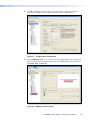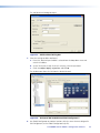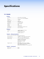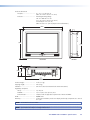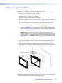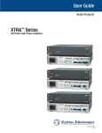
1
User Guide
TouchLink™
TLP 1000MV and TLP 1000TV
TouchLink Touchpanels
68-1909-01 Rev. B
01 12
Safety Instructions • English
This symbol is intended to alert the user of important operating and
maintenance (servicing) instructions in the literature provided with the
equipment.
This symbol is intended to alert the user of the presence of uninsulated
dangerous voltage within the product enclosure that may present a risk of
electric shock.
Warning
Power sources • This equipment should be operated only from the power source indicated on the product. This
equipment is intended to be used with a main power system with a grounded (neutral) conductor. The third
(grounding) pin is a safety feature, do not attempt to bypass or disable it.
Power disconnection • To remove power from the equipment safely, remove all power cords from the rear of the
equipment, or the desktop power module (if detachable), or from the power source receptacle (wall plug).
Power cord protection • Power cords should be routed so that they are not likely to be stepped on or pinched by
items placed upon or against them.
Caution
Servicing • Refer all servicing to qualified service personnel. There are no user-serviceable parts inside. To prevent
the risk of shock, do not attempt to service this equipment yourself because opening or removing covers may
expose you to dangerous voltage or other hazards.
Retain Instructions • The safety instructions should be kept for future reference.
Slots and openings • If the equipment has slots or holes in the enclosure, these are provided to prevent
overheating of sensitive components inside. These openings must never be blocked by other objects.
Read Instructions • Read and understand all safety and operating instructions before using the equipment.
Follow Warnings • Follow all warnings and instructions marked on the equipment or in the user information.
Avoid Attachments • Do not use tools or attachments that are not recommended by the equipment
manufacturer because they may be hazardous.
Consignes de Sécurité • Français
Ce symbole sert à avertir l’utilisateur que la documentation fournie avec le
matériel contient des instructions importantes concernant l’exploitation et la
maintenance (réparation).
Ce symbole sert à avertir l’utilisateur de la présence dans le boîtier
de l’appareil de  tensions dangereuses non isolées posant des risques
d’électrocution.
Attention
Lire les instructions• Prendre connaissance de toutes les consignes de sécurité et d’exploitation avant d’utiliser
le matériel.
Conserver les instructions• Ranger les consignes de sécurité afin de pouvoir les consulter à l’avenir.
Respecter les avertissements • Observer tous les avertissements et consignes marqués sur le matériel ou
présentés dans la documentation utilisateur.
Eviter les pièces de fixation • Ne pas utiliser de pièces de fixation ni d’outils non recommandés par le fabricant
du matériel car cela risquerait de poser certains dangers.
Sicherheitsanleitungen • Deutsch
Lithium battery • There is a danger of explosion if battery is incorrectly replaced. Replace it only with the same or
equivalent type recommended by the manufacturer. Dispose of used batteries according to the instructions of
the manufacturer.
Avertissement
Alimentations • Ne faire fonctionner ce matériel qu’avec la source d’alimentation indiquée sur l’appareil. Ce
matériel doit être utilisé avec une alimentation principale comportant un fil de terre (neutre). Le troisième
contact (de mise à la terre) constitue un dispositif de sécurité : n’essayez pas de la contourner ni de la
désactiver.
Déconnexion de l’alimentation• Pour mettre le matériel hors tension sans danger, déconnectez tous les cordons
d’alimentation de l’arrière de l’appareil ou du module d’alimentation de bureau (s’il est amovible) ou encore de
la prise secteur.
Protection du cordon d’alimentation • Acheminer les cordons d’alimentation de manière à ce que personne ne
risque de marcher dessus et à ce qu’ils ne soient pas écrasés ou pincés par des objets.
Réparation-maintenance • Faire exécuter toutes les interventions de réparation-maintenance par un technicien
qualifié. Aucun des éléments internes ne peut être réparé par l’utilisateur. Afin d’éviter tout danger
d’électrocution, l’utilisateur ne doit pas essayer de procéder lui-même à ces opérations car l’ouverture ou le
retrait des couvercles risquent de l’exposer à de hautes tensions et autres dangers.
Fentes et orifices • Si le boîtier de l’appareil comporte des fentes ou des orifices, ceux-ci servent à empêcher les
composants internes sensibles de surchauffer. Ces ouvertures ne doivent jamais être bloquées par des objets.
Lithium Batterie • Il a danger d’explosion s’il y a remplacment incorrect de la batterie. Remplacer uniquement
avec une batterie du meme type ou d’un type equivalent recommande par le constructeur. Mettre au reut les
batteries usagees conformement aux instructions du fabricant.
Vorsicht
Dieses Symbol soll dem Benutzer in der im Lieferumfang enthaltenen
Dokumentation besonders wichtige Hinweise zur Bedienung und Wartung
(Instandhaltung) geben.
Stromquellen • Dieses Gerät sollte nur über die auf dem Produkt angegebene Stromquelle betrieben werden.
Dieses Gerät wurde für eine Verwendung mit einer Hauptstromleitung mit einem geerdeten (neutralen) Leiter
konzipiert. Der dritte Kontakt ist für einen Erdanschluß, und stellt eine Sicherheitsfunktion dar. Diese sollte nicht
umgangen oder außer Betrieb gesetzt werden.
Dieses Symbol soll den Benutzer darauf aufmerksam machen, daß im Inneren
des Gehäuses dieses Produktes gefährliche Spannungen, die nicht isoliert sind
und die einen elektrischen Schock verursachen können, herrschen.
Stromunterbrechung • Um das Gerät auf sichere Weise vom Netz zu trennen, sollten Sie alle Netzkabel aus der
Rückseite des Gerätes, aus der externen Stomversorgung (falls dies möglich ist) oder aus der Wandsteckdose
ziehen.
Achtung
Lesen der Anleitungen • Bevor Sie das Gerät zum ersten Mal verwenden, sollten Sie alle Sicherheits-und
Bedienungsanleitungen genau durchlesen und verstehen.
Aufbewahren der Anleitungen • Die Hinweise zur elektrischen Sicherheit des Produktes sollten Sie
aufbewahren, damit Sie im Bedarfsfall darauf zurückgreifen können.
Befolgen der Warnhinweise • Befolgen Sie alle Warnhinweise und Anleitungen auf dem Gerät oder in der
Benutzerdokumentation.
Keine Zusatzgeräte • Verwenden Sie keine Werkzeuge oder Zusatzgeräte, die nicht ausdrücklich vom Hersteller
empfohlen wurden, da diese eine Gefahrenquelle darstellen können.
Instrucciones de seguridad • Español
Este símbolo se utiliza para advertir al usuario sobre instrucciones
importantes de operación y mantenimiento (o cambio de partes) que se
desean destacar en el contenido de la documentación suministrada con los
equipos.
Este símbolo se utiliza para advertir al usuario sobre la presencia de
elementos con voltaje peligroso sin protección aislante, que puedan
encontrarse dentro de la caja o alojamiento del producto, y que puedan
representar riesgo de electrocución.
Precaucion
Leer las instrucciones • Leer y analizar todas las instrucciones de operación y seguridad, antes de usar el
equipo.
Conservar las instrucciones • Conservar las instrucciones de seguridad para futura consulta.
Obedecer las advertencias • Todas las advertencias e instrucciones marcadas en el equipo o en la
documentación del usuario, deben ser obedecidas.
Evitar el uso de accesorios • No usar herramientas o accesorios que no sean especificamente recomendados
por el fabricante, ya que podrian implicar riesgos.
安全须知 • 中文
这个符号提示用户该设备用户手册中有重要的操作和维护说明。
这个符号警告用户该设备机壳内有暴露的危险电压,有触电危险。
注意
阅读说明书
保存说明书
遵守警告 •
避免追加 •
• 用户使用该设备前必须阅读并理解所有安全和使用说明。
• 用 户应保存安全说明书以备将来使用。
用户应遵守产品和用户指南上的所有安全和操作说明。
不要使用该产品厂商没有推荐的工具或追加设备,以避免危险。
Schutz des Netzkabels • Netzkabel sollten stets so verlegt werden, daß sie nicht im Weg liegen und niemand
darauf treten kann oder Objekte darauf- oder unmittelbar dagegengestellt werden können.
Wartung • Alle Wartungsmaßnahmen sollten nur von qualifiziertem Servicepersonal durchgeführt werden. Die
internen Komponenten des Gerätes sind wartungsfrei. Zur Vermeidung eines elektrischen Schocks versuchen
Sie in keinem Fall, dieses Gerät selbst öffnen, da beim Entfernen der Abdeckungen die Gefahr eines
elektrischen Schlags und/oder andere Gefahren bestehen.
Schlitze und Öffnungen • Wenn das Gerät Schlitze oder Löcher im Gehäuse aufweist, dienen diese zur
Vermeidung einer Überhitzung der empfindlichen Teile im Inneren. Diese Öffnungen dürfen niemals von
anderen Objekten blockiert werden.
Litium-Batterie • Explosionsgefahr, falls die Batterie nicht richtig ersetzt wird. Ersetzen Sie verbrauchte Batterien nur
durch den gleichen oder einen vergleichbaren Batterietyp, der auch vom Hersteller empfohlen wird. Entsorgen
Sie verbrauchte Batterien bitte gemäß den Herstelleranweisungen.
Advertencia
Alimentación eléctrica • Este equipo debe conectarse únicamente a la fuente/tipo de alimentación eléctrica
indicada en el mismo. La alimentación eléctrica de este equipo debe provenir de un sistema de distribución
general con conductor neutro a tierra. La tercera pata (puesta a tierra) es una medida de seguridad, no
puentearia ni eliminaria.
Desconexión de alimentación eléctrica • Para desconectar con seguridad la acometida de alimentación eléctrica
al equipo, desenchufar todos los cables de alimentación en el panel trasero del equipo, o desenchufar el
módulo de alimentación (si fuera independiente), o desenchufar el cable del receptáculo de la pared.
Protección del cables de alimentación • Los cables de alimentación eléctrica se deben instalar en lugares donde
no sean pisados ni apretados por objetos que se puedan apoyar sobre ellos.
Reparaciones/mantenimiento • Solicitar siempre los servicios técnicos de personal calificado. En el interior no
hay partes a las que el usuario deba acceder. Para evitar riesgo de electrocución, no intentar personalmente la
reparación/mantenimiento de este equipo, ya que al abrir o extraer las tapas puede quedar expuesto a voltajes
peligrosos u otros riesgos.
Ranuras y aberturas • Si el equipo posee ranuras o orificios en su caja/alojamiento, es para evitar el
sobrecalientamiento de componentes internos sensibles. Estas aberturas nunca se deben obstruir con otros
objetos.
Batería de litio • Existe riesgo de explosión si esta batería se coloca en la posición incorrecta. Cambiar esta batería
únicamente con el mismo tipo (o su equivalente) recomendado por el fabricante. Desachar las baterías usadas
siguiendo las instrucciones del fabricante.
警告
电源 • 该设备只能使用产品上标明的电源。 设备必须使用有地线的供电系统供电。 第三条线(
地线)是安全设施,不能不用或跳过 。
拔掉电源 • 为安全地从设备拔掉电源,请拔掉所有设备后或桌面电源的电源线,或任何接到市电
系统的电源线。
电源线保护 • 妥善布线, 避免被踩踏,或重物挤压。
维护 • 所有维修必须由认证的维修人员进行。 设备内部没有用户可以更换的零件。为避免出现触
电危险不要自己试图打开设备盖子维修该设备。
通风孔 • 有些设备机壳上有通风槽或孔,它们是用来防止机内敏感元件过热。 不要用任何东西
挡住通风孔。
锂电池 • 不正确的更换电池会有爆炸的危险。必须使用与厂家推荐的相同或相近型号的电池。按
照生产厂的建议处理废弃电池。
FCC Class A Notice
This equipment has been tested and found to comply with the limits for a Class A digital device, pursuant to part 15
of the FCC Rules. Operation is subject to the following two conditions:
1. This device may not cause harmful interference.
2. This device must accept any interference received, including interference that may cause undesired operation.
The Class A limits are designed to provide reasonable protection against harmful interference when the equipment is
operated in a commercial environment. This equipment generates, uses, and can radiate radio frequency energy and,
if not installed and used in accordance with the user guide, may cause harmful interference to radio communications.
Operation of this equipment in a residential area is likely to cause harmful interference, in which case the user will be
required to correct the interference at his own expense.
NOTE: This unit was tested with shielded cables on the peripheral devices. Shielded cables must be used with
the unit to ensure compliance with FCC emissions limits.
For more information on safety guidelines, regulatory compliances, EMI/EMF compliance, accessibility, and
related topics, click here.
Conventions Used in this Guide
In this user guide, the following are used:
CAUTION: A caution indicates a potential hazard to equipment or data.
NOTE: A note draws attention to important information.
TIP:
A tip provides a suggestion to make working with the application easier.
WARNING: A warning warns of things or actions that might cause injury, death, or
other severe consequences.
Commands are written in the fonts shown here:
^AR Merge Scene,,Op1 scene 1,1 ^B 51 ^W^C
[01] R 0004 00300 00400 00800 00600 [02] 35 [17] [03]
E X! *X1& *X2) *X2# * X2! CE}
NOTE: For commands and examples of computer or device responses mentioned
in this guide, the character “0” is used for the number zero and “O”
represents the capital letter “o.”
Computer responses and directory paths that do not have variables are written in the
font shown here:
Reply from 208.132.180.48: bytes=32 times=2ms TTL=32
C:\Program Files\Extron
Variables are written in slanted form as shown here:
ping xxx.xxx.xxx.xxx —t
SOH R Data STX Command ETB ETX
Selectable items, such as menu names, menu options, buttons, tabs, and field names are
written in the font shown here:
From the File menu, select New.
Click the OK button.
Copyright
© 2012 Extron Electronics. All rights reserved.
Trademarks
All trademarks mentioned in this guide are the properties of their respective owners
Contents
Introduction............................................................ 1
About the TLP 1000MV and TLP 1000TV............. 1
Features............................................................... 1
Requirements....................................................... 3
Computer Software and Hardware................... 3
Other Hardware............................................... 3
Specifications........................................................ 34
Accessories and Part Numbers.......................... 40
Included Parts................................................ 40
Optional Parts................................................ 40
Panel Features......................................................... 4
Mounting............................................................... 41
TLP 1000MV Front and Top Panel
Features and Operations..................................... 4
Reset Buttons and LED..................................... 5
TLP 1000MV Rear Panel
Features and Connections................................... 6
TLP 1000TV Front Panel
Features and Operations..................................... 9
TLP 1000TV Rear Panel
Features and Connections................................. 10
Rack Mounting the TLP 1000MV....................... 41
Underwriters Laboratories Guidelines for
Rack Mounting............................................. 41
Rack Mounting the TLP 1000MV.................... 41
Wall Mounting the TLP 1000MV........................ 42
Furniture Mounting the TLP 1000MV................. 43
Wall Mounting the TLP 1000MV with
a Wall Box........................................................ 44
Desktop Mounting the TLP 1000TV................... 44
Freestanding.................................................. 44
Swivel Mount Adapter................................... 44
Removing the TLP 1000TV Base for VESA
Mounting......................................................... 45
VESA Mounting the TLP 1000TV........................ 46
Initial Calibration................................................. 14
How to Access the Internal On-screen Menus.... 14
Main Screen....................................................... 14
Volume Screen................................................... 15
Time Screen....................................................... 16
Network Screen................................................. 16
Video Screen...................................................... 17
Touch Calibration Screen.................................... 17
Reset Modes.......................................................... 47
Configuration Software..................................... 18
The Configuration Software............................... 18
Installing the Software....................................... 18
GUI Configurator and Global Configurator
Installation.................................................... 18
Using the TouchLink Panel Web Pages................ 19
Updating the Firmware...................................... 21
Updating Firmware Using Extron Firmware
Loader.......................................................... 21
Updating Firmware Using GUI Configurator... 22
Updating Firmware From a Web Browser....... 23
Using GUI Configurator..................................... 24
Using Global Configurator................................. 29
TLP 1000MV and TLP 1000TV • Contents
v
TLP 1000MV and TLP 1000TV • Contents
vi
Introduction
This guide describes the function, installation and operation of the TouchLink™
TLP 1000MV and TLP 1000TV panels. Unless otherwise stated, the terms “TLP 1000
Series,” “TLP 1000,” “touchpanel,” and “TouchLink panel” refer to both models. The
guide also provides information about optional accessories that are available from Extron
for both panels.
This section provides information:
•
About the TLP 1000MV and TLP 1000TV
•
Features of the TLP 1000MV and TLP 1000TV
•
Computer Software and Hardware Requirements
•
Other Hardware Requirements
About the TLP 1000MV and TLP 1000TV
Both units have a 10.1 inch widescreen display with a resolution of 1024x600. The screen
displays graphic objects and text, which are associated with user-defined functions. The
touch overlay allows the user to initiate or activate functions by touching the objects on
the screen.
The screen layout is designed with the Extron GUI Configurator software. Functions are
assigned to the screen objects with the Extron Global Configurator software. The user can
define the graphics and the functions associated with those graphics, providing versatility
and adaptability to the configuration and control of an AV system.
A motion sensor, light sensor, and two speakers provide sleep mode, auto dimming, and
audible feedback.
The TLP 1000MV is intended to be wall or rack mounted.
The TLP 1000TV comes with a stand that allows it to be placed on a desktop. If the stand
is removed, the unit can be mounted on a wall or furniture, using the Extron LPVM‑1
VESA® mount kit (part number 60-1099-02).
Features
10.1-inch LCD screen — displays a range of graphic objects and text on a 1024x600 pixel
screen.
Touch screen overlay — provides simple and intuitive control over a range of functions
by touching the icons displayed on the screen.
Video preview — allows video preview with an MTP input.
GUI Configurator and Global Configurator Software — allows the user to design a
custom graphical user interface and associate a range of different functions with objects in
that display. No programming knowledge is needed.
Easy configuration and flexibility — on-screen graphics and text, as well as the
functions associated with them, can be easily changed to adapt the control panel to the
evolving needs of the system, avoiding the need for additional control modules.
TLP 1000MV and TLP 1000TV • Introduction
1
Ethernet connection — provides an inexpensive, easily installed, cabling option for
connecting products located anywhere else on the network.
Power over the Ethernet (PoE) — twisted pair cable carries network information and
48 VDC from the power supply to the touchpanel.
Compatibility with most Extron IP Link® products — allows easy integration into
existing systems.
TCP/IP
Network
Extron
IPL 250
Motion
Detector
IP Link-Ethernet
Control Interface
Ext
Contact
Closure
Extron
IN1508
RE
1
M
CO
RX
TX
1
G
S
S
G
RE
3
Extron
TLP 1000MV
LAY4
IR 4
RX
M
CO
RX
TX
N
LA
1
2
M1 SC TS
CO RT
TX
Scaling Presentation
Switcher
3
3
UT
INP 4
3
2
S
G
S
G
R
WE
PO
12VmA
500X
MA
RS-232
UT
TP
RS-
OU
10" TouchLink
Panel
232
A
B
L
R
L
6
5
UT
DIO3
INP
4
8
ron
LAY2
IR 2
R
7
AU
2
1
UT
L
RGB
, R-Y
B-Y
R
TP
Extron
XPA 1002
OU
D
LISTE
1T23
U S I.T.E.
C
Y,
6
8
DVI
RGB
Power Amplifier
7
RGB
3 YC
R-Y
1 VID
B-Y
I
Hz
50-60
40V
100-2
N
T
Y
VID
P
U
5
4
2
XPA
DVD
Player
1002
Extron
SI 28
IR Control
to DVD
Surface-mount
Speakers
CT
1
OVER
TEMP
2
/PROTE
LIMITER
SIGNAL
Relay
RS-232
Laptop
Extron
IR Emitter
Relay
Projector
Lighting
System
Screen
Control
PC
DVI Output
IR Control
from IPL 250
Figure 1. TLP 1000MV Application Diagram
Programmable LEDs — provide feedback about various system states, as defined by the
user.
Light sensor — adjusts LCD screen backlighting to compensate for ambient lighting.
Motion sensor — When no motion is detected for a user-defined period of time, the
unit enters sleep mode to conserve power. When a user approaches the screen, the panel
detects motion and is reactivated.
Loudspeaker — provides audible feedback in response to events triggered by the user.
Kensington lock support — allows the touchpanel to be locked to a table or other flat
surface.
Multiple mounting options — The TLP 1000MV can be wall-mounted, rack-mounted,
or furniture‑mounted.
The TLP 1000TV comes with a stand that allows it to stand on a desktop or be mounted
on the Extron swivel mount adapter (SMA-1). If the stand is removed, the unit can be
VESA‑mounted on a wall or furniture using the Extron LPVM-1.
See the list of optional parts on page 40 for the part numbers.
Choice of colors for TLP 1000MV — The TLP 1000MV is available in
•
black (part number 60-1105-02)
•
white (part number 60-1105-03)
TLP 1000MV and TLP 1000TV • Introduction
2
Requirements
Computer Software and Hardware
The latest system requirements for running the configuration software can be found on the
Extron Website:
zz
GUI Configurator
zz
Global Configurator
Other Hardware
An Extron IP Link control processor must also be connected to the same network domain
as the TouchLink panel. Suggested models include:
•
IPL T S series (for example IPL T S4)
•
IPL 250
•
IPL T CR48
•
IPL T SFI244
•
IPCP 305
•
IPCP 505
See the Extron Website (www.extron.com) for further information about these products.
TLP 1000MV and TLP 1000TV • Introduction
3
Panel Features
This section describes:
TLP 1000MV Front Panel Features and Operations
TLP 1000MV Rear Panel Features and Connections
TLP 1000TV Front Panel Features and Operations
TLP 1000TV Rear Panel Features and Connections
TLP 1000MV Front and Top Panel Features and Operations
d
d
e
a
b
c
f
Figure 2. TLP 1000MV Front Panel
a Motion sensor — is capped with a small Fresnel lens that focuses light onto the
sensor. When no motion has been detected for a user-defined period of time, the
unit enters sleep mode. When motion is detected by the sensor, the screen display is
restored and active.
b Microphone — is located below the LCD screen.
c Connection status LED — is unlit during normal operation. Blinks red if the
connection to the IP Link controller is lost.
d Configurable LEDs (2) — two LEDs on the top corners of the panel can be
programmed by the user to provide information about the system. The LEDs can be
programmed to light red or green and have two rates (blinking and always on).
TLP 1000MV and TLP 1000TV • Panel Features
4
e LCD screen — has a 1024x600 resolution with a touch overlay. A graphical user
interface, designed using the Extron GUI Configurator software (see page 24),
displays buttons, text, or icons on the screen. These are configured for a range of
user‑defined functions, using the Extron Global Configurator software (see
page 29).
f Speakers — two speakers located under the screen, on either side of the panel,
provide audible feedback for the user.
g
Figure 3.
TLP 1000MV Top View
g Light sensor — mounted on top of the display frame. The sensor monitors the level
of ambient light and adjusts the screen brightness and button backlighting. The
sensor can only be viewed from above the panel.
Reset Buttons and LED
There are two buttons and an LED recessed behind the faceplate.
h
ij
Figure 4. TLP 1000MV Front Panel with the Bezel Removed
h Menu button — activates the on-screen menus for calibrating the unit (see
page 14).
i Reset button — allows the unit to be reset in any of four different modes. For further
information see “Reset Modes” on page 47.
j Reset LED — provides feedback about the reset status when the user presses the
reset button. For further information see “Reset Modes” on page 47.
TLP 1000MV and TLP 1000TV • Panel Features
5
TLP 1000MV Rear Panel Features and Connections
k
l m
n
Figure 5. TLP 1000MV Rear Panel Features
k MTP signal adjustment controls — use a small screwdriver to adjust these three
MTP signal variables: S-video luminance gain (VID/Y), S-video chrominance gain (C),
and sharpness (S). For composite video signals, the gain is controlled by the VID/Y
adjustment.
l MTP input — connect a twisted pair cable, terminated with an RJ‑45 connector, to
provide video and audio input from an Extron MTP transmitter.
CAUTION: Connect the MTP transmitter to the MTP socket and the network
connector to the network socket. Although both use RJ-45
connectors, the MTP socket (on the left) must be connected to an
MTP transmitter and the network socket (on the right) must be
connected to a LAN. The wires on each connector use different
voltages and inputting the wrong voltages into a socket will damage
the TLP 1000MV.
TLP 1000MV and TLP 1000TV • Panel Features
6
m Network and Power over Ethernet connector — the
LAN
TLP 1000MV connects to a network using a twisted pair cable,
terminated with an RJ‑45 connector.
RJ-45 Port
Link LED
The network port has two LEDs. The green LED lights solid to
Activity LED
indicate that the touchpanel is connected correctly to a network.
The yellow LED flashes to indicate that data is being passed to or from the touchpanel.
An Extron IP Link control processor must also be connected to the same network
domain. Suggested models are listed on page 3.
Use a straight-through Ethernet cable to connect the panel to a switch or router. Use a
crossover cable to connect the panel directly to a computer.
Extron recommends using a Power over Ethernet (PoE) power supply. Use a
straight‑through Ethernet cable to connect the power supply to a switch or router.
This cable carries network information from the switch or router to the power supply
input. Connect a second straight-through cable to carry the network information and
48 VDC from the power supply to the TLP 1000MV. Connect the IEC power cord from
the PoE power supply to a convenient 100 VAC to 240 VAC, 50-60 Hz power source.
Power over Ethernet (PoE) Power Supply
PWR LAN-OUT
To TLP 1000MV
Figure 6.
LAN-IN
To Network Switch
Connecting the Power over Ethernet Power Supply
CAUTIONS: • The TLP 1000MV and TLP 1000TV are intended for connection to
a Power over Ethernet circuit for intrabuilding use only and are
considered a Network Environment 0 per IEC TR62101.
•Always use a power supply supplied or specified by Extron. Use
of an unauthorized power supply voids all regulatory compliance
certification and may damage the supply and end product.
• Extron power supplies are certified to UL/CSA 60950-1 and
are classified as LPS (Limited Power Source). Use of a non-LPS
or unlisted power supply will void all regulatory compliance
certification.
• Unless otherwise stated, the AC/DC adapters are not suitable for
use in air handling spaces or in wall cavities. The power supply is
to be located within the same vicinity as the Extron AV processing
equipment in an ordinary location, Pollution Degree 2, secured to
the equipment rack within the dedicated closet, podium or desk.
Power over Ethernet (PoE) is intended for indoor use only. No part
of the network that uses PoE can be routed outdoors.
• The installation must always be in accordance with the applicable
provisions of National Electrical Code ANSI/NFPA 70, article 75 and
the Canadian Electrical Code part 1, section 16. The power supply
shall not be permanently fixed to building structure or similar
structure.
TLP 1000MV and TLP 1000TV • Panel Features
7
n Power connector — connect the two pole, 3.5 mm captive screw connector from
the 12 VDC, 1.0 A power supply (not provided) to the power supply socket on the
rear panel. Ensure the connections have the correct polarity as shown below.
NOTES: • Extron recommends using the Power over Ethernet power supply.
This 12 VDC, 1.0 A power supply should be used only for setup or
troubleshooting.
•If both power supplies are connected to the TLP 1000MV, the PoE power
supply takes precedence.
Smooth
Ridges
A
Power Receptacle
A
SECTION A–A
Power Supply
Output Cord
DC Power Cord
Captive Screw Connector
3/16"
(5 mm) Max.
Ground
+12 VDC
External
Power Supply
(12 VDC, 1 A )
AC Power Cord
Figure 7.
Power Supply Connection
CAUTIONS: • Always use a power supply supplied by or specified by Extron. Use
of an unauthorized power supply voids all regulatory compliance
certification and may cause damage to the supply and the end
product.
• Unless otherwise stated, the AC/DC adapters are not suitable for
use in air handling spaces or in wall cavities. The power supply is
to be located within the same vicinity as the Extron AV processing
equipment in an ordinary location, Pollution Degree 2, secured to
the equipment rack within the dedicated closet, podium or desk.
• The installation must always be in accordance with the applicable
provisions of National Electrical Code ANSI/NFPA 70, article 75 and
the Canadian Electrical Code part 1, section 16. The power supply
shall not be permanently fixed to building structure or similar
structure.
NOTES: • The length of the exposed wires in the stripping process is critical. The
ideal length is 3/16 inches (5 mm). Any longer and the exposed wires
may touch, causing a short circuit between them. Any shorter and the
wires can be easily pulled out even if tightly fastened by the captive
screws.
• Do not tin the wires. Tinned wire does not hold its shape and can
become loose over time.
TLP 1000MV and TLP 1000TV • Panel Features
8
TLP 1000TV Front Panel Features and Operations
d
d
e
a
f
b
c
Figure 8. TLP 1000TV Front Panel Features
a Motion sensor — is capped with a small Fresnel lens that focuses light onto the
sensor. When no motion has been detected for a user-defined period of time, the
unit enters sleep mode. When motion is detected by the sensor, the screen display is
restored and active.
b Microphone — is located below the LCD screen.
c Connection status LED — is unlit during normal operation. Blinks red if the
connection to the IP Link controller is lost.
d Configurable LEDs (2) — on the top corners of the panel can be programmed by the
user to provide information about the system. The LEDs can be programmed to light
red or green and have two rates (blinking and always on).
e LCD screen — has a 1024x600 resolution with a touch overlay. A graphical user
interface, designed using the Extron GUI Configurator software (see page 24),
displays buttons, text, or icons on the screen (page 24). These are configured for a
range of user‑defined functions, using the
Extron Global Configurator software
(see page 29).
f Speakers — two speakers located under
7
the screen, on either side of the panel,
provide audible feedback for the user.
g Light sensor — (see the figure to the
right) mounted on top of the display frame.
The sensor monitors the level of ambient
light and adjusts the screen brightness and
button backlighting. The sensor can only
be viewed from above the panel.
TLP 1000MV and TLP 1000TV • Panel Features
9
TLP 1000TV Rear Panel Features and Connections
The TLP 1000TV has a stand that allows it to be placed on desktop. The stand can be
removed to VESA mount the unit. Both the stand and the touchpanel have removable
covers that conceal the rear panel features and protect cables that are attached to the
TLP 1000TV.
The rear and base covers can be removed using the Extron removal tool (see page 45).
n
k
h
i
j
l
m
o
p
Figure 9. TLP 1000TV Rear Features
The following features and connections are available on the back panel.
h Menu button — activates the on-screen menus for calibrating the unit (see
page 14).
i Reset button — allows the unit to be reset in any of four different modes (see
“Reset Modes” on page 47).
j Reset LED — provides feedback about the reset status when the user presses the
reset button (see “Reset Modes” on page 47).
k MTP signal adjustment controls — three MTP signal adjustments are available for
S-video luminance gain (VID/Y), S-video chrominance gain (C), and sharpness (S). For
composite video signals, the gain is controlled by the VID/Y adjustment.
TLP 1000MV and TLP 1000TV • Panel Features
10
l MTP input — a twisted pair cable, terminated with an RJ‑45 connector, provides
video and audio input from an Extron MTP transmitter. The MTP port is in the top
surface of the recessed area (see the red arrow in figure 9).
CAUTION: Connect the MTP transmitter to the MTP socket and the network
connector to the network socket. Although both use RJ-45
connectors, the MTP socket (on the left) must be connected to an
MTP transmitter and the network socket (on the right) must be
connected to a LAN. The wires on each connector use different
voltages and inputting the wrong voltages into a socket will damage
the TLP 1000TV.
m Network and Power over Ethernet connector — the TLP 1000TV connects to a
network using a twisted pair cable, terminated with an RJ‑45 connector. The LAN port
is in the top surface of the recessed area (see the blue arrow in figure 9).
The LAN port has two LEDs. The green LED lights solid to
indicate that the touchpanel is connected correctly to a network.
The yellow LED flashes to indicate that data is being passed to
or from the touchpanel.
LAN
An Extron IP Link control processor must also be connected to
the same network domain. Suggested models are listed on page 3.
RJ-45 Port
Link LED
Activity LED
Use a straight-through Ethernet cable to connect the panel to a switch or router. Use a
crossover cable to connect the panel directly to a computer.
Extron recommends using a Power over Ethernet (PoE) power supply. Use a
straight‑through Ethernet cable to connect the power supply to a switch or router.
This cable carries network information from the switch or router to the power supply
input. Connect a second straight-through cable to carry the network information and
48 VDC from the power supply to the TLP 1000TV. Connect the IEC power cord from
the PoE power supply to a convenient 100 VAC to 240 VAC, 50-60 Hz power source.
Power over Ethernet (PoE) Power Supply
PWR LAN-OUT
To TLP 1000MV
LAN-IN
To Network Switch
Figure 10. Connecting the Power over Ethernet Power Supply
CAUTION: See the cautions on page 7 for important information about using a
Power over Ethernet power supply.
NOTE: The twisted pair cable providing the MTP and network connections should
be secured together and to both the back panel and base using zip-ties
(see figure 11, on the next page).
TLP 1000MV and TLP 1000TV • Panel Features
11
LAN Connector
MTP Connector
Zip-tie Holder
Cable Runway
Zip-tie Holder
Figure 11. Connecting and Securing Cables
n Power connector — connect the two pole, 3.5 mm captive screw connector from
the 12 VDC, 1.0 A power supply (not provided) to the power supply socket on the
rear panel. Ensure the connections have the correct polarity as shown below.
NOTES: • Extron recommends using the Power over Ethernet power supply.
The 12 VDC, 1.0 A power supply should be used only for setup or
troubleshooting.
•If both power supplies are connected to the TLP 1000TV, the PoE power
supply takes precedence.
Smooth
Ridges
A
A
SECTION A–A
Power Receptacle
Power Supply
Output Cord
DC Power Cord
Captive Screw Connector
3/16"
(5 mm) Max.
Ground
+12 VDC
AC Power Cord
External
Power Supply
(12 VDC, 1 A )
Figure 12. Power Supply Connection
CAUTION: See the cautions on page 8 for important information about power
supplies.
NOTE: See the notes on page 8 for important information about wiring captive
screw connectors.
TLP 1000MV and TLP 1000TV • Panel Features
12
o VESA mounting holes (4) — for wall mounting, use these four holes, arranged in
a pattern that is in accordance with the VESA FDMI standard, type D 75 mm (see
“VESA mounting the TLP 1000TV” on page 46).
p Kensington Security Slot — allows the touchpanel to be locked to a table or other
flat surface. The lock is not provided and must be purchased separately.
TLP 1000MV and TLP 1000TV • Panel Features
13
Initial
Configuration
and Calibration
This section describes:
•
How to Access the Internal On-screen Menus
•
The Main, Volume, Time, Network, and Video screens
•
The Screen Touch Calibration Screen
How to Access the Internal On-screen Menus
When the TouchLink panel first has power applied, the unit boots up and displays the
opening screen. To access the on-screen menus, press the Menu button (see page 5 for
the TLP 1000MV or page 10 for the TLP 1000TV).
The menus open at the Main screen. There are five different screens (Main, Volume,
Time, Network, and Video) that can be selected by pressing the appropriate button at
the left side of the screen.
There is also an Exit button at the bottom left corner of the screen. Pressing this button
applies and saves any changes and leaves the menu screens.
Main Screen
Main
Volume
Sleep timer: 300 Sec
Down
Up
Auto Backlight
PoE
Active
On
Time
Network
Video
Backlight: 073%
Down
Up
Wake on Motion
On
Exit
Figure 13.Main Screen
Values can be changed by pressing the buttons to highlight them. Press the Down or Up
buttons to adjust the values or press the Auto Backlight or Wake on Motion buttons to
toggle between Off and On. The current setting is shown above the buttons.
TLP 1000MV and TLP 1000TV • Initial Configuration and Calibration
14
The sleep timer determines how long the panel will be inactive before it enters Sleep
mode, when the screen goes dark to save power. The time can be changed from 0 to
50,000 seconds (in 10‑second increments). The time that is currently selected is shown
above the buttons.
The screen may need a high level of backlighting for readability when ambient lighting is
high. With low ambient lighting, the backlighting should be low.
Auto Backlight provides a suitable amount of backlighting that is automatically
calculated from the amount of ambient light detected by the light detector.
The Backlight control sets the backlighting manually from 0 to 100 percent, when Auto
Backlight is set to Off.
NOTE: When Auto Backlight is set to On, changing the percentage of Backlight does
not affect the amount of backlighting.
Wake on Motion activates the panel from Sleep mode when motion is detected near the
unit. Use the on-screen buttons to toggle the Auto Backlight or Wake on Motion options
between Off and On.
Volume Screen
Master: 120
Main
Down
Volume
Up
Click: 120
Time
Down
Network
Up
Sounds: 120
Video
Down
Up
Line In: 120
Down
Exit
Up
Figure 14.Volume Screen
Press the Down or Up buttons to highlight one of the adjustable audio features. Use the
Down and Up buttons to adjust the following settings:
•
Master volume (between 0 and 255; default 120) sets the maximum volume for
all the other sound volume settings. For example, if the master volume is set to 200
(approximately 80 percent of maximum), even when the Line In volume is set to 255
(maximum), it will only be equivalent to 80 percent of maximum.
•
Click (between 0 and 255; default 120) sets the volume for audible feedback that
accompanies events such as a screen button being pressed.
•
Sounds (between 0 and 255; default 120) sets the volume of audio from any audio
file playback.
•
Line In (between 0 and 255; default 120) sets the volume of the audio signal received
through the line in from an Extron MTP transmitter.
TLP 1000MV and TLP 1000TV • Initial Configuration and Calibration
15
Time Screen
Main
Volume
Month: 07
Down
Up
Hours: 13
Down
Up
Time
Day: 06
Minutes: 32
Network
Down
Up
Down
Up
Video
Year: 2009
Down
Up
Exit
Figure 15.Time Screen
Use the Down or Up buttons to adjust the Month, Day, Year, Hours, and Minutes.
NOTE: The Hours value uses the 24‑hour clock. For 10 am, set hours to 10; for
10 pm, set hours to 22.
Network Screen
MAC: 00-05-A6-07-3A-55
Main
Volume
IP Address
192.168.254.254
1
2
3
4
5
6
7
8
9
.
0
Clear
Time
Subnet Mask
Network
Video
255.255.0.0
DHCP
Off
Exit
Figure 16.Network Screen
To set the IP address or subnet mask, press the appropriate button. When one of the
buttons is selected, an on‑screen keypad appears that allows the user to select “Clear,”
or digits between 0 and 9, and “.” (dot).
NOTE: The factory default IP address for both the TLP 1000MV and TLP 1000TV is
192.168.254.254. The default subnet mask is 255.255.0.0. Consult with
your IT department to ensure these addresses are correctly assigned.
Toggle between On and Off to enable or disable Dynamic Host Configuration Protocol
(DHCP). This determines whether the unit will have a permanent IP address or will have
one provided by the network, when required. The default setting is Off.
TLP 1000MV and TLP 1000TV • Initial Configuration and Calibration
16
Video Screen
Main
Volume
Time
Network
Contrast: 064
Down
Up
Color: 064
Down
Brightness: 128
Down
Up
Up
Tint: 128
Down
Up
Video
Exit
Figure 17.Video Screen
When a video input is connected to the MTP input, the video can be previewed in the
small gray rectangle on the screen. The preview allows you to adjust the following video
properties, using the appropriate Down or Up buttons:
•
Contrast between 0 and 127 (default, 64)
•
Color between 0 and 127 (default, 64)
•
Brightness between 0 and 255 (default, 128)
•
Tint between 0 and 255 (default, 128)
Touch Calibration Screen
After setting the Main, Volume, Time, Network, and Video values, press the Menu
button a second time to begin calibrating the touch area of the touchpanel.
+
+
Press and Hold
Highlighted Box
Until Color Changes
+
+
Figure 18.Touch Calibration Screen
Press on the green box until the color reverts to gray with a white border and a second
box is highlighted. Repeat until all four boxes have been pressed and calibrated. At that
point the screen automatically returns to the Main screen (see page 14).
Exit the on-screen menus, by pressing the Exit button in the bottom left corner of the
menu screens.
TLP 1000MV and TLP 1000TV • Initial Configuration and Calibration
17
Configuration
Software
This section of the user guide provides information about:
•
The Configuration Software
•
Installing the Software
•
Using the TouchLink Panel Web Pages
•
Updating the Firmware
•
Using GUI Configurator
•
Using Global Configurator
The Configuration Software
Create a graphical user interface (GUI) for the TouchLink panel in two steps:
1. Design the layout of the text and graphics using GUI Configurator.
2. Assign functions to the text and graphics using Global Configurator.
The GUI Configurator software is a Windows-based application. The interface is designed
either by customizing an existing template or by designing an entirely new interface. GUI
Configurator offers several templates to manage control system devices.
After the GUI has been designed on a PC, the project is saved, built, and uploaded to
the TouchLink panel to verify what it looks like on the screen. It is then imported from
the TLP unit to Global Configurator where control functions are assigned to the text and
graphic items in the layout. After assigning the control functions, the project is rebuilt and
uploaded to the controller.
These two programs provide versatility and adaptability for configuration and control of an
AV system as it grows and evolves.
Installing the Software
GUI Configurator and Global Configurator Installation
NOTE: You must use Global Configurator 3.1 or a later version and
GUI Configurator 1.2 or a later version to configure the TLP 1000MV or
TLP 1000TV.
Insert the disc provided into the DVD-ROM drive of the computer. If the setup program
does not start automatically, run Launch.exe from the DVD-ROM directory in Windows
My Computer. Select the Software tab, locate the GUI Configurator program and click
Install. Follow the on-screen instructions.
By default, the Installer program creates and places the GUI Configurator program in the
C:\Program Files\Extron\GUI Configurator folder. An icon may also be placed on
the Windows desktop.
TLP 1000MV and TLP 1000TV • Configuration Software
18
If required, locate the Global Configurator program on the disc or website and install that
also. By default, the Installer program creates and places the Global Configurator program
in the C:\Program Files\Extron\GCx.x folder, where x.x represents the version of the
Global Configurator program. During installation, there is an option to place an icon on
the Windows desktop.
Both programs can be downloaded from the Extron website (www.extron.com). Select
the Download tab and click the Software option in the sidebar at the left. Navigate to
GUI Configurator or Global Configurator and click Download next to the program. Follow
the on‑screen instructions to complete installation. A folder is created on the C:\ drive and
an icon may be placed on the desktop.
Using the TouchLink Panel Web Pages
Both the TouchLink panels have default web pages that can be used to read and change
the current settings of the panels. The web pages can be accessed as follows:
1. Open your browser and type the IP address of the TLP 1000 unit into the address field.
The browser opens the TouchLink panel Status page, which is read-only and provides
basic information about the model, date and time, and IP settings.
Figure 19. System Status Page
TLP 1000MV and TLP 1000TV • Configuration Software
19
2. Click the Configuration tab and select System Settings, which allows the user
to modify the IP settings and the date and time settings. These correspond to the
network settings (see page 16) and time settings (see page 16) in the on‑screen
menus.
Figure 20. System Settings Page
3. Selecting Passwords allows the user to set passwords for an administrator and a user.
To set a password, follow the instructions at the top of the page.
Figure 21. Passwords Page
4. To upgrade the firmware, select Firmware Upgrade. More detailed instructions are
found in the “Updating Firmware from a Web Browser” section on page 23.
TLP 1000MV and TLP 1000TV • Configuration Software
20
5. Click the Touchpanel tab to open the Touchpanel Configuration page, which allows
the user to alter the touchpanel and volume settings. These correspond to the main
settings (see page 14) and volume settings (see page 15) in the on-screen menus.
Figure 22. Touchpanel Configuration Page
Updating the Firmware
Firmware for both touchpanels can be upgraded using the Extron Firmware Loader,
using the TLP 1000 default web page, or using GUI Configurator. Before starting,
consult your IT team and ensure that the touchpanel has a unique IP address.
Updating Firmware Using Extron Firmware Loader
1. Power on a computer that is connected to the same network as the touchpanel.
2. Install the Extron Firmware Loader utility onto the computer if it is not already present.
This is on the software disc that ships with unit or can be downloaded, free of charge,
from the Extron website (www.extron.com).
To install from the disc, insert the disc into the DVD-ROM drive of the computer and
follow the same procedure as for installing the GUI Configurator and Global
Configurator programs (see page 18).
To install from the Extron website (www.extron.com), select the Download tab and
click the Software tab. Locate the Firmware Loader and click Download. Follow the
on-screen instructions to complete installation.
TLP 1000MV and TLP 1000TV • Configuration Software
21
3. From the same site, download the firmware for the TouchLink panel. Click the
Download tab on the Extron home page and select the Firmware option.
Figure 23. Extron Web Page — Download Center
4. Navigate to the TLP 1000MV or TLP 1000TV firmware and click Download.
This downloads the firmware to your computer. Note the folder in which the firmware
file is saved.
5. Open the Extron Firmware Loader by clicking on the desktop icon.
6. Select TLP 1000MV or TLP 1000TV from the Device drop-down menu.
7. Select TCP/IP from the Connection Method drop-down menu.
8. Enter the IP address for the TLP 1000, a Telnet port number (this will usually be 23),
and a password. Click Connect.
9. In the New Firmware File “Path” pane, navigate to the file that was saved in step 4.
Click the Add button. The main Firmware Loader screen opens with the TLP 1000MV
or TLP 1000TV listed in the device pane.
10.Click Begin. The firmware transfer begins and takes approximately three minutes.
When the Total Progress bar shows “Completed”, select Exit from the File menu to
exit Firmware Loader.
Updating Firmware Using GUI Configurator
1. Set up the computer and touchpanel as described in steps 1 and 2 in the previous
section (“Updating firmware using Extron Firmware Loader“). If necessary,
install the Extron Firmware Loader utility onto the computer (see “Installing the
Software”).
2. Find the firmware on the Extron website and download it to your computer, as
described in steps 4 and 5 in the previous section.
3. Open GUI Configurator. Open Firmware Loader by clicking on Firmware Update
Manager... in the Tools menu.
Figure 24. Opening Firmware Loader from GUI Configurator
4. Follow steps 7 to 10 from the previous section, “Updating Firmware Using Extron
Firmware Loader”.
TLP 1000MV and TLP 1000TV • Configuration Software
22
Updating Firmware From a Web Browser
1. Power on a computer that is connected to the same network as the TLP 1000.
2. From the Extron website (www.extron.com), download the firmware for the
touchpanel. Click the Download tab on the Extron home page and select the
Firmware option (see figure 23).
3. Navigate to the touchpanel firmware and click Download.
4. This downloads the firmware to your computer. Note the folder in which the firmware
file is saved.
5. Open your browser and type the IP address of the TLP 1000 unit into the address box.
The browser opens the TouchLink panel web pages (see page 19).
Figure 25. Firmware Upgrade Web Page
6. Click the Configuration tab at the top of the page and then select
Firmware Upgrade from the bar on the left.
7. Use the Browse button to navigate to and select the firmware file that was saved in
step 4.
8. Click Upload. The Touchpanel screen shows the message “Firmware Uploading...
Please Wait...”. When the firmware is uploaded, the screen shows the message
“Restarting...”. Once the firmware is installed, the panel can be calibrated using the
on‑screen menus (see page 14) or the TouchLink panel web pages (see page 19).
TLP 1000MV and TLP 1000TV • Configuration Software
23
Using GUI Configurator
This section provides an overview of the GUI Configurator program. For complete
information about the program, consult the GUI Configurator help file (select Contents in
the Help menu or press the <F1> key while within the program).
NOTE: To configure the touchpanel, use GUI Configurator version 1.2 or later.
To use the GUI Configurator program, follow these instructions:
1. Double-click the desktop icon. A splash screen appears momentarily and then the
program opens at the main screen behind the GUI Configurator Start Options dialog
box.
Figure 26. Opening GUI Configurator
Figure 27. GUI Configurator Start Options Dialog Box
TLP 1000MV and TLP 1000TV • Configuration Software
24
2. You can choose to:
•
Start a New Project — Clicking OK opens a dialog box that offers a choice of
project options.
Figure 28. GUI Configurator New Project Dialog Box
A series of icons offer you the choice of creating a project with a template
or without a template and allow you to select the size and type of Touchlink
panel. If you are creating a project from an existing template, you can use the
factory created templates or you can select a template that you have previously
created.
•
Open an Existing Project — Clicking OK opens a dialog box that allows you
to navigate to an existing project for modification.
Figure 29. GUI Configurator Dialog Box to Open an Existing Project
TLP 1000MV and TLP 1000TV • Configuration Software
25
Navigate to the existing file and select it. A preview with information about the
file appears in the pane on the right.
If you are working on the project, leave the Open as read-only box unchecked.
Click Open to open the file. The project opens in GUI Configurator.
•
Download an Existing Project from a Panel — Clicking OK opens a dialog
box that allows you to download a file that has been uploaded to a panel.
Figure 30.GUI Configurator Download Project Dialog Box
In the dialog box that opens, enter the IP address of the panel and use the
Browse button to navigate to a folder where the file will be saved.
Check Open the project and Close Download Manager.
Click OK. The project is downloaded to your computer and opens in
GUI Configurator.
TLP 1000MV and TLP 1000TV • Configuration Software
26
3. Depending on which option was selected in step 2, GUI Configurator opens to a new
or existing project. The initial screen is divided into a series of panes offering a range
of tools that can be used to design or modify the project. For full details on how to
use these tools, consult the help file (in the Help menu click Contents, or press the
<F1> key while within the program).
Figure 31. GUI Configurator Main Screen
4. To save the project, select Save Project from the File menu. The project file is
saved. If this is the first time saving the project file, the Save As dialog box appears. If
the Save As dialog box appears:
a. Browse for the location where the project file is to be saved.
b. Enter a file name for the project.
c. Click Save.
TLP 1000MV and TLP 1000TV • Configuration Software
27
5. The project can be uploaded to one or more TouchLink panels. To add a panel:
a. From the Project menu, select Add > Panel:
Figure 32.Add a TouchLink Panel
The Panel Manager dialog box opens:
Figure 33.Panel Manager Dialog Box
b. Click the Add Panel icon (shown to the right) to add a new panel to
the left pane.
c. Highlight the name of the panel in the left pane to display the
properties of that panel in the right pane.
d. The default IP address (192.168.254.254) is assigned to any new panel that is
added. To change the IP address, highlight the address property in the right pane
and type in the correct IP address. Update any other properties, as required.
e. Repeat steps 5b - 5d to add further panels, if required.
6. To upload a project to a TouchLink panel:
a. From the Project menu, select Upload to Selected Panels. The Build
Manager dialog box opens, showing the build progress. After the build is
complete, this dialog box closes and the File Upload Manager screen opens. The
upload begins automatically.
b. Select Close this dialog when upload completes check box in the
Automatic Settings section so that the File Upload Manager screen closes
automatically when the upload completes. This option can be set before or during
the upload.
TLP 1000MV and TLP 1000TV • Configuration Software
28
If this project has been uploaded to the TouchLink panel before, you can choose to
upload only the changes that have been made since the previous upload. You can also
choose to upload the new version to some, specified touchpanels or all the TouchLink
panels on the list found within the Devices section of the File Upload Manager screen
during the upload process.
Using Global Configurator
NOTE: To configure the touchpanel, use Global Configurator version 3.1 or later.
This section provides an overview of the Global Configurator program. For complete
information about the program, consult the Global Configurator help file (click Contents
in the Help menu or press the <F1> key while within the program).
This section describes how to set up Global Configurator project with an IPL 250. Setting
up a project with another IP Link product is similar but you should consult the Global
Configurator help file for exact information about the product you are using.
1. Double-click the GC3 desktop icon. The Global Configurator 3 Start Options box
opens.
Figure 34. Global Configurator 3 Start Options
TLP 1000MV and TLP 1000TV • Configuration Software
29
2. Select Create A New Project and click OK. The dialog box closes, leaving the
Project Settings screen.
Figure 35. Global Configurator Project Settings
3. Configure the device settings:
a. Enter the IP address for the IP Link control processor.
b. The default Telnet connection is port 23 and HTTP is port 80, so these values do
not usually need to be changed.
c. If necessary, set administrator and user passwords.
d. If required, set the date and time.
e. Checking the Set Device as GlobalViewer Host box is optional. For more
information about what a GlobalViewer host is, see the Global Configurator help
file.
TLP 1000MV and TLP 1000TV • Configuration Software
30
4. Click OK. The Project Settings screen closes and is replaced by the Add Device dialog
box:
Figure 36. Global Configurator Add Device Dialog Box
To see all the options, click the Advanced >>> button. The button name changes to
Basic <<< (as shown in the figure above).
a. Select the IP Link device from the drop-down menu. In figure 36, above, an
IPL 250 controller is added.
b. Enter the IP address of the IP Link control processor. The default value is
192.168.254.254, but this may have been changed. Check with your IT
department to verify the address.
c. Enter a display name into the text box. This is what the device will be known as in
the Global Configurator project.
d. Checking the Make this device a GlobalViewer Host check box is optional.
e. Set the Telnet port (usually 23) and the web port (usually 80).
f. If the controller is password protected, enter the password now.
g. In the right pane, set up a GlobalViewer tree, (see the Global Configurator help
file).
TLP 1000MV and TLP 1000TV • Configuration Software
31
5. Click OK. The Add Device screen closes. The start-up screen, which was behind it, is
now visible, showing the IP Link control processor and the available ports:
Figure 37. Configuring an IP Link Device
6. Select TouchPanel Port 1. The screen shows the available options for the TouchLink
panel. To add the GUI Configurator project that was uploaded to the TouchLink panel,
click Click here to add one.
Figure 38. Adding a TouchLink Panel
TLP 1000MV and TLP 1000TV • Configuration Software
32
The Add TouchPanel dialog box opens.
Figure 39. Add TouchPanel Dialog Box
7. Select the settings to add a touchpanel.
a. Ensure the TouchLink panel model is selected from the drop-down menu and
enter the IP address.
b. Set the Telnet port (usually 23) and, if necessary, enter the password.
c. Check the Import/Apply Layout box and click OK.
The window now shows the GUI from the TouchLink panel.
Figure 40. Touchpanel GUI Loaded Onto Global Configurator 3
8. Use Global Configurator to associate functions with the screen elements designed in
GUI Configurator (see the Global Configurator help file).
TLP 1000MV and TLP 1000TV • Configuration Software
33
Specifications
TLP 1000MV
Display
Screen type������������������������������������ Active matrix TFT color display
Size������������������������������������������������ 10.1" (25.7 cm), measured diagonally
Resolution�������������������������������������� 1024x600
Dot/pixel pitch�������������������������������� 118 dpi
Aspect ratio������������������������������������ Widescreen
Color depth������������������������������������ 18 bit, 256k colors
Transparency���������������������������������� 8 bit alpha channel
Brightness�������������������������������������� 200 nits (cd/m2)
Contrast����������������������������������������� 500:1
Backlight���������������������������������������� High bright LED
Viewing angle�������������������������������� ±70° horizontal, +50°/-60° vertical
Touch screen���������������������������������� Resistive membrane
Memory
SDRAM������������������������������������������ 128 MB for graphics processing
8 MB for system use
Flash���������������������������������������������� 32 MB for project storage
16 MB for system use
Control — Ethernet interface
Ethernet control/communications port
1 RJ-45 female connector
Ethernet data rate�������������������������� 10/100Base-T, half/full duplex with autodetect
Ethernet protocol��������������������������� ICMP, IP, TCP (control), UDP, DHCP, Telnet
Default settings������������������������������ Link speed and duplex level: autodetected
IP address = 192.168.254.254
Subnet mask = 255.255.0.0
Default gateway = 0.0.0.0
DHCP = off
Program control����������������������������� Extron Global Configurator v3.1 or higher
GUI Configurator v1.2 or higher for Windows®
Extron Simple Instruction Set (SIS™)
Microsoft® Internet Explorer® ver. 6 or higher, Telnet
Control — touchpanel
Motion sensor�������������������������������� On/off
Light sensor������������������������������������ On/off
TLP 1000MV and TLP 1000TV • Specifications
34
Video input — see S-video or composite video MTP transmitters' specifications
Number/signal type������������������������ 1 proprietary analog signal from an Extron MTP AV transmitter
Connectors������������������������������������ 1 female RJ-45
Standards��������������������������������������� NTSC, PAL
Audio input — see S-video or composite video MTP transmitters' specifications
Number/signal type������������������������ 1 stereo, balanced/unbalanced, line level, as part of a set of proprietary signals
from an Extron MTP
Connector�������������������������������������� 1 female RJ-45 (shared with video input)
Audio output
Speaker output������������������������������ 2 mono, 86 dB SPL, 0.1 watt, 0.1 m, half space
Frequency response������������������������ 750 Hz to 20 kHz, ±5 dB
Playback format(s)�������������������������� WAV files: 8 bit PCM, mono, 8 kHz sampling
General
Power�������������������������������������������� Supplied by an included power over Ethernet (PoE) adapter or by an optional
external 12 VDC, 1 A power supply
Power supply���������������������������������� External
Input: 100-240 VAC, 50-60 Hz
Output: PoE 802.3af compliant, 48 VDC, 0.35 A, 16.8 watts
Power consumption
Device������������������������������������� 12.7 watts, 48 VDC (PoE)
Device and power supply��������� 15.3 watts, 100-240 VAC, 50-60 Hz
Power over Ethernet (PoE) input requirements
Complies with PoE 802.3af, class 3
Temperature/humidity�������������������� Storage: -4 to +140 °F (-20 to +60 °C) / 10% to 90%, noncondensing
Operating: +32 to +122 °F (0 to +50 °C) / 10% to 90%, noncondensing
Cooling������������������������������������������ Convection, vents on top and bottom
Thermal dissipation
Device������������������������������������� 43.5 BTU/hr
Device and power supply��������� 52.3 BTU/hr
Mounting
Rack mount����������������������������� With optional kit
Furniture or wall mount����������� With included hardware or optional accessores
Enclosure type�������������������������������� Plastic
TLP 1000MV and TLP 1000TV • Specifications
35
Enclosure dimensions
Faceplate��������������������������������� 8.1" H x 11.2" W x 0.5" D
(20.6 cm H x 28.5 cm W x 1.3 cm D)
Enclosure��������������������������������� Excluding mounting flange:
7.0" H x 10.0" W x 2.3" D*
(17.7 cm H x 25.3 cm W x 5.8 cm D*)
*In-wall depth: 2.3" (5.8 cm)
(Allow at least 2.75" [7.0 cm] depth in the wall/furniture.)
11.20"
(28.46 cm)
8.11"
(20.61 cm)
6.96"
(17.69 cm)
SIDE VIEW
FRONT VIEW
0.50"
(1.27 cm)
2.76"
(7.02 cm)
2.26"
(5.75 cm)
9.96"
(25.30 cm)
BOTTOM VIEW
Product weight������������������������������� 2.7 lbs (1.2 kg)
Shipping weight����������������������������� 6 lbs (3 kg)
Vibration���������������������������������������� ISTA 1A in carton (International Safe Transit Association)
Regulatory compliance
Safety�������������������������������������� CE, c-UL, UL
EMI/EMC��������������������������������� CE, C-tick,FCC Class A, ICES, VCCI
Environmental�������������������������� Complies with the applicable requirements of RoHS and WEEE.
MTBF��������������������������������������������� 30,000 hours
Warranty���������������������������������������� 3 years parts and labor; touchscreen display and overlay components are covered
for 1 year
NOTE: All nominal levels are at ±10%.
NOTE: Specifications are subject to change without notice.
TLP 1000MV and TLP 1000TV • Specifications
36
TLP 1000TV
Display
Screen type������������������������������������ Active matrix TFT color display
Size������������������������������������������������ 10.1" (25.7 cm), measured diagonally
Resolution�������������������������������������� 1024x600
Dot/pixel pitch�������������������������������� 118 dpi
Aspect ratio������������������������������������ Widescreen
Color depth������������������������������������ 18 bit, 256k colors
Transparency���������������������������������� 8 bit alpha channel
Brightness�������������������������������������� 200 nits (cd/m2)
Contrast����������������������������������������� 500:1
Backlight���������������������������������������� High bright LED
Viewing angle�������������������������������� ±70° horizontal, +50°/-60° vertical
Touch screen���������������������������������� Resistive membrane
Memory
SDRAM������������������������������������������ 128 MB for graphics processing
8 MB for system use
Flash���������������������������������������������� 32 MB for project storage
16 MB for system use
Control — Ethernet interface
Ethernet control/communications port
1 female RJ-45 connector
Ethernet data rate�������������������������� 10/100Base-T, half/full duplex with autodetect
Ethernet protocol��������������������������� ICMP, IP, TCP (control), UDP, DHCP, Telnet
Default settings������������������������������ Link speed and duplex level: autodetected
IP address = 192.168.254.254
Subnet mask = 255.255.0.0
Default gateway = 0.0.0.0
DHCP = off
Program control����������������������������� Extron Global Configurator v3.1 or higher
GUI Configurator v1.2 or higher for Windows®
Extron Simple Instruction Set (SIS™)
Microsoft® Internet Explorer® ver. 6 or higher, Telnet
Control — touchpanel
Motion sensor�������������������������������� On/off
Light sensor������������������������������������ On/off
Video input — see S-video or composite video MTP transmitters' specifications
Number/signal type������������������������ 1 proprietary analog signal from an Extron MTP AV transmitter
Connectors������������������������������������ 1 female RJ-45
Standards��������������������������������������� NTSC, PAL
Audio input — see S-video or composite video MTP transmitters' specifications
Number/signal type������������������������ 1 stereo, balanced/unbalanced, line level, as part of a set of proprietary signals
from an Extron MTP
Connector�������������������������������������� 1 female RJ-45 (shared with video input)
TLP 1000MV and TLP 1000TV • Specifications
37
Audio output
Speaker output������������������������������ 2 mono, 86 dB SPL, 0.1 watt, 0.1 m, half space
Frequency response������������������������ 750 Hz to 20 kHz, ±5 dB
Playback format(s)�������������������������� WAV files: 8 bit PCM, mono, 8 kHz sampling
General
Power�������������������������������������������� Supplied by an included power over Ethernet (PoE) adapter or by an optional
external 12 VDC, 1 A power supply
Power supply���������������������������������� External
Input: 100-240 VAC, 50-60 Hz
Output: PoE 802.3af compliant, 48 VDC, 0.35 A, 16.8 watts
Power consumption
Device������������������������������������� 12.7 watts, 48 VDC (PoE)
Device and power supply��������� 15.3 watts, 100-240 VAC, 50-60 Hz
Power over Ethernet (PoE) input requirements
Complies with PoE 802.3af, class 3
Temperature/humidity�������������������� Storage: -4 to +140 °F (-20 to +60 °C) / 10% to 90%, noncondensing
Operating: +32 to +122 °F (0 to +50 °C) / 10% to 90%, noncondensing
Cooling������������������������������������������ Convection, vents on top rear
Thermal dissipation
Device������������������������������������� 43.5 BTU/hr
Device and power supply��������� 52.3 BTU/hr
Mounting
Furniture or wall mount����������� Set on tabletop or mount to optional VESA D 75 mm panel mount kit
Adjustment ranges������������������������� Tilts through a 45° range
Enclosure type�������������������������������� Plastic
TLP 1000MV and TLP 1000TV • Specifications
38
Enclosure dimensions��������������������� 7.2" H x 10.0" W x 7.3" D
(18.2 cm H x 25.4 cm W x 18.6 cm D)
(Includes base. Total height depends on screen tilt. See the following diagrams.)
TLP 1000TV
10.00"
(25.40 cm)
75° Min. Tilt
7.18"
(18.23 cm)
7.18"
(18.24 cm)
5.94"
(15.08 cm)
7.3"
(18.57 cm)
FRONT VIEW
SIDE VIEW
3.07"
(7.80 cm)
2.48"
(6.31 cm)
4.96"
(12.60 cm)
30° Max. Tilt
7.3"
(18.57 cm)
BOTTOM VIEW
SIDE VIEW
Product weight������������������������������� 5.2 lbs (2.4 kg)
Shipping weight����������������������������� 8 lbs (4 kg)
Vibration���������������������������������������� ISTA 1A in carton (International Safe Transit Association)
Regulatory compliance
Safety�������������������������������������� CE, c-UL, UL
EMI/EMC��������������������������������� CE, C-tick, FCC Class A, ICES, VCCI
Environmental�������������������������� Complies with the applicable requirements of RoHS and WEEE.
MTBF��������������������������������������������� 30,000 hours
Warranty���������������������������������������� 3 years parts and labor; touchscreen display and overlay components are covered
for 1 year
NOTE: All nominal levels are at ±10%.
NOTE: Specifications are subject to change without notice.
TLP 1000MV and TLP 1000TV • Specifications
39
Accessories and
Part Numbers
Included Parts
Description
Part Number
TLP 1000MV TouchLink panel (wall mount, black)
60-1105-02
TLP 1000MV TouchLink panel (wall mount, white)
60-1105-03
TLP 1000TV TouchLink panel (desk top or VESA mount)
60-1104-02
Power over Ethernet power supply
70-828-01
Extron removal tool
Extron Software Products DVD
Cut-out Template (TLP 1000MV only)
TLP 1000MV Setup Guide or TLP 1000TV Setup Guide
Optional Parts
Description
Part Number
RM 1000M rack mounting kit for TLP 1000MV
70-886-01
BB 1000M back box for TLP 1000MV
70-887-01
EWB 1000 external wall box for TLP 1000MV (black)
70-950-02
EWB 1000 external wall box for TLP 1000MV (white)
70-950-03
LPVM-1 VESA mounting kit for TLP 1000TV
60-1099-02
SMA-1 swivel mount adapter for TLP 1000TV
70-747-01
#6 Spanner head screwdriver
100-710-01LF
PS 1210 C 12 VDC, 1.0 A desktop power supply with captive screw
connector
70-775-01
IPL T S1 IP Link Control Processor
60-801-81
IPL T S2 IP Link Control Processor
60-544-81
IPL T S4 IP Link Control Processor
60-544-83
IPL T S6 IP Link Control Processor
60-544-84
IPL 250 IP Link Control Processor
60-1026-81
IPL T CR48 IP Link Control Processor
60-544-85
IPL T SFI244 IP Link Control Processor
60-544-86
IPCP 305 IP Link Control Processor
60-1072-02
IPCP 505 IP Link Control Processor
60-1071-02
TLP 1000MV and TLP 1000TV • Specifications
40
Mounting
This section outlines the various options for:
•
Rack Mounting the TLP 1000MV
•
Wall Mounting the TLP 1000MV
•
Surface Mounting the TLP 1000MV
•
Wall Mounting the TLP 1000MV with a Wallbox
•
Desktop Mounting the TLP 1000TV
•
Removing the TLP 1000TV base for VESA Mounting
•
VESA mounting the TLP 1000TV
Rack Mounting the TLP 1000MV
Underwriters Laboratories Guidelines for Rack Mounting
The following Underwriters Laboratories (UL) guidelines are relevant to the safe installation
of these products in a rack:
Elevated operating ambient temperature — If the unit is installed in a closed or
multi-unit rack assembly, the operating ambient temperature of the rack environment
may be greater than room ambient temperature. Therefore, install the equipment in an
environment compatible with the maximum ambient temperature (Tma: +122 °F, +50 °C)
specified by Extron.
Reduced air flow — Install the equipment in the rack so that the equipment gets
adequate air flow for safe operation.
Mechanical loading — Mount the equipment in the rack so that uneven mechanical
loading does not create a hazardous condition.
Circuit overloading — Connect the equipment to the supply circuit and consider the
effect that circuit overloading might have on overcurrent protection and supply wiring.
Give appropriate consideration to the equipment nameplate ratings when addressing this
concern.
Reliable earthing (grounding) — Maintain reliable grounding of rack-mounted
equipment. Pay particular attention to supply connections other than direct connections to
the branch circuit (such as the use of power strips).
Rack Mounting the TLP 1000MV
The TLP 1000MV can be mounted in any standard 19-inch equipment rack, using the
optional Extron RM 1000M rack mounting kit (part number 70-886-01). Follow the
instructions provided with the kit.
TLP 1000MV and TLP 1000TV • Mounting
41
Wall Mounting the TLP 1000MV
The TLP 1000MV can be mounted in the wall or through furniture.
To mount the TLP 1000MV directly into a wall, follow these steps.
1. Determine the best location for the TLP 1000MV.
2. Use the template provided to mark the wall and then cut a hole 10.22 inches
(25.96 cm) wide x 7.16 inches (18.2 cm) high.
3. Unpack the TLP 1000MV and remove the faceplate.
4. Ensure all the locking arms are flush with the unit and check that the TLP 1000MV can
fit into the hole. If necessary, use a rasp or a coarse file to enlarge the hole.
5. Run the network cable and video connectors inside the wall to the hole, leaving
enough slack in the cables to connect them to the back of the TLP 1000MV.
6. Plug the cables into the rear panel connectors (see pages 6 - 8).
•
Connect the LAN port to the network with a straight-through cable, providing
both a network connection and power from a Power over Ethernet power supply.
•
Connect an S-video or composite video source to the RJ-45 MTP input.
•
Optional: Extron recommends using the Power over Ethernet power supply
provided. However, you may use the LAN port only as a network connection and
connect a 12 VDC, 1.0 A power supply (not provided) to the 2-pole captive screw
power input. See the cautions on page 7 for very important information about
power supplies.
7. Push excess cables into the wall cavity.
8. Ensure the five locking arms (three at the top and two at the bottom) are flush with
top and bottom of the TLP 1000MV and fit the touchpanel into the hole.
9. Using a Phillips head screwdriver, tighten the screws for the locking arms. As the
screws tighten, the locking arms rotate behind the wall and hold the unit in place. Do
not overtighten the screws as this can damage the locking arms or the wall.
Faceplate snaps to unit
(4 places on each side).
Locking Arms
(3 on top edge,
2 on bottom edge)
Tighten screws to
rotate locking arms.
Figure 41. Securing the TLP 1000MV to a Wall with Locking Arms
10.If required, perform the initial calibration (see page 14).
11.Replace the faceplate by pressing the catches on the faceplate into the corresponding
holes on the front of the panel (four places on each side).
TLP 1000MV and TLP 1000TV • Mounting
42
Furniture Mounting the TLP 1000MV
The TLP 1000MV can be mounted into the surface of a lectern as follows.
1. Determine the best location for the TLP 1000MV.
2. Use the template provided to mark the lectern and then cut a hole 10.22 inches
(25.96 cm) wide x 7.16 inches (18.2 cm) high.
3. Unpack the TLP 1000MV and remove the faceplate.
4. Ensure all the locking arms are flush with the unit and check that the TLP 1000MV can
fit into the hole. If necessary, use a rasp or a coarse file to enlarge the hole.
5. With the TLP 1000MV in position, mark four holes for screws, where the unit will be
secured to the lectern.
6. Remove the TLP 1000MV and, if necessary, drill four pilot holes into the lectern.
7. Run the network cable and video connectors to the lectern, leaving enough slack to
connect them to the back of the TLP 1000MV.
8. Plug the cables into the rear panel connectors (see pages 6 - 8).
•
Connect the LAN port to the network with a straight-through cable, providing
both a network connection and power from a Power over Ethernet power supply.
•
Connect an S-video or composite video source to the RJ-45 MTP input.
•
Optional: Extron recommends using the Power over Ethernet power supply
provided. However, you may use the LAN port only as a network connection and
connect a 12 VDC, 1.0 A power supply (not provided) to the 2-pole captive screw
power input. See the cautions on page 7 for very important information about
power supplies.
9. Push excess cables into the lectern.
10.Ensure the five locking arms (three at the top and two at the bottom) are flush with
top and bottom of the TLP 1000MV, and then fit the touchpanel into the hole.
11.Secure the touchpanel to the lectern with four #4 screws (not provided), using the
pilot holes drilled in step 6.
12.Replace the faceplate by pressing the catches on the faceplate into the corresponding
holes on the front of the panel (four places on each side).
Faceplate snaps to unit
(4 places on each side)
12
Drill holes for
mounting screws (4).
6
11
2
Cut hole for
mounting the unit.
Secure unit with
mounting screws (4).
Figure 42. Mounting the TLP 1000MV in a Lectern
TLP 1000MV and TLP 1000TV • Mounting
43
Wall Mounting the TLP 1000MV with a Wall Box
The TLP 1000MV can be wall mounted using the Extron BB 1000M back box (part number
70‑887‑01) or the Extron EWB 1000M external wall box (part number 70-950-0x). Follow
the instructions provided with the appropriate wall box.
Desktop Mounting the TLP 1000TV
Freestanding
The TLP 1000TV comes assembled with a stand that allows it to be placed on a desktop.
If required, use two screws through the two holes in the base to secure the unit to the
desktop.
Mounting Holes (2)
Figure 43.TLP 1000TV Base, Showing Mounting Holes
1. Drill two holes through the desktop from underneath. The two holes must be
3.07 inches (78 mm) apart.
2. Fasten the base to the desktop with two #8 wood screws through the desktop from
underneath into the two holes in the base.
Swivel Mount Adapter
The TLP 1000TV can be mounted with the Extron SMA-1 swivel mount adapter. This
allows the unit to be mounted permanently yet swivel up to 180° in either direction.
1. Remove the back cover and base cover, using the Extron removal tool, as described in
“Removing the TLP 1000TV Base for VESA Mounting“ on the next page.
2. Set the TLP 1000TV on its back on a flat surface and remove the screw holding the
locking plate at the bottom of the base. This releases the weight, which can be
removed, leaving the mounting hole that will fit over the conduit of the SMA-1.
Locking Plate
Locking Screw
Figure 44. TLP 1000TV Base, Showing Locking Plate and Screw
3. Attach the conduit, insulation disk, and swivel disk and configure the set screws to
allow for the degree of swivel that is required (see the SMA-1 Swivel Mount Adapter
Kit User Guide, available at www.extron.com).
4. Place the mounting hole in the base over the conduit of the SMA-1.
5. Secure the touchpanel to the SMA-1 with the backing plate and locking nut (see the
SMA-1 Swivel Mount Adapter Kit User Guide).
TLP 1000MV and TLP 1000TV • Mounting
44
Removing the TLP 1000TV Base for VESA Mounting
Notch to Remove
Back Cover
Notch to Remove
Base Cover
Figure 45.Removing the Back and Base Covers
1. Remove the back cover by inserting the Extron removal tool (provided) into the
notches on each side.
2. Remove the base cover by inserting the Extron removal tool into the notches on the
base.
VESA Mounting Holes (4)
Spanner Drive
Security Screws
(2 for each Hinge)
Hinges (2)
Cable Runway
Figure 46.TLP 1000TV with the Base and Back Covers Removed
TLP 1000MV and TLP 1000TV • Mounting
45
3. If necessary, cut the zip tie holding the twisted pair cables to the TLP 1000TV base.
4. If necessary, remove the cables from the cable runway in the base.
5. Remove the four screws holding the hinges to the touchpanel.
NOTE: The spanner drive screws holding the hinges require a #6 spanner bit or
#6 spanner head screwdriver, which are not provided.
VESA Mounting the TLP 1000TV
1. Before attaching the VESA mounting kit, remove the base and back of the
TLP 1000TV, as described in the previous section.
2. If necessary, connect the cables and fasten them to the back of the touchpanel with
zip ties.
3. Attach the small back cover (provided). Fit the bottom catches into the slots on the
bottom of the panel and snap the side catches into place.
4. Once the base and back have been removed,VESA mount the TLP 1000TV by securing
plate 2 of the Extron LPVM-1 (part number 60-1099-02) to the four VESA mounting
holes (see the figure below). Follow the instructions provided with the mounting kit.
LPVM-1 Plate 2
Security Screws (4)
Small Back Cover
Figure 47. VESA Mounting the TLP 1000TV with the LPVM-1
TLP 1000MV and TLP 1000TV • Mounting
46
Reset Modes
The TLP 1000MV and TLP 1000TV have four reset modes that correspond to four of the
five reset modes for the IP Link controllers. The modes are initiated by pressing the Reset
button.
To access the Reset button on the TLP 1000MV, remove the faceplate. See page 5 to
locate the Reset button on the TLP 1000MV. The Reset button on the TLP 1000TV is on
the back panel (see page 10).
TLP 1000MV and TLP 1000TV Reset Mode Summary
Mode Activation
Run/Stop
Events
Use Factory
Firmware
1
Purpose/Notes
The TLP 1000 reverts to the factory default
firmware. Event scripting does not start if the
TLP 1000 is powered on in this mode. All user files
and settings (drivers, adjustments, IP settings, etc.)
are maintained.
NOTE: If you do not want to update firmware, or
you performed a mode 1 reset by mistake, cycle
power to the TLP 1000 to return to the
firmware version that was running prior to the
mode 1 reset. Use the 0Q SIS command to
confirm that the factory default firmware is no
longer running (look for asterisks following the
version number).
This mode reverts to
the factory default
firmware version if
incompatibility
issues arise with
user-loaded
firmware.
NOTE:
User-defined web
pages may not
work correctly if
using an earlier
firmware version.
Hold down the Reset button for
about 3 seconds until the Reset LED
blinks once, then release and press
Reset momentarily (<1 second) within
1 second.
This mode turns events on or off.
This mode is useful
for troubleshooting.
Hold down the Reset button for
about 6 seconds until the Reset LED
blinks twice (once at 3 seconds, again
at 6 seconds). Then release and press
Reset momentarily (for <1 second)
within 1 second.
This mode:
• Enables ARP capability.
• Sets the IP address back to factory default
(192.168.254.254).
• Sets the subnet back to factory default.
• Sets the default gateway address to the factory
default.
• Sets port mapping back to factory default.
• Turns DHCP off.
• Turns events off.
This mode enables
you to set IP address
information using
ARP and the MAC
address.
This mode performs a complete reset to
factory defaults (except the firmware).
• Does everything mode 4 does.
• Removes button/touchpanel configurations.
• Resets all IP options.
• Removes scheduling settings.
• Removes/clears all files from TLP 1000.
This mode is useful
if you want to start
over with
configuration and
uploading, and also
to replace events.
Hold down the recessed Reset
button while applying power to the
TLP 1000.
NOTE: After a mode 1 reset is
performed, update the TLP 1000
firmware to the latest version. Do
not operate the firmware version
that results from this mode reset.
If you want to use the factory
default firmware, you must upload
that version again. See page 21 for
details on uploading firmware.
3
Reset all
IP Settings
4
Reset to
Factory Defaults
Result
NOTE: Nothing happens if the
momentary press does not occur
within 1 second.
5
Hold down the Reset button for
about 9 seconds until the Reset LED
blinks three times (once at 3
seconds, again at 6 seconds, again at
9 seconds). Then release and press
Reset momentarily (for <1 second)
within 1 second.
NOTE: Nothing happens if the
momentary press does not occur
within 1 second.
NOTE: Nothing happens if the momentary press
does not occur within 1 second.
TLP 1000MV and TLP 1000TV • Reset Modes
47
Extron Warranty
Extron Electronics warrants this product against defects in materials and workmanship for a period of three years from
the date of purchase; touchscreen display and overlay components are covered for 1 year. In the event of malfunction
during the warranty period attributable directly to faulty workmanship and/or materials, Extron Electronics will, at
its option, repair or replace said products or components, to whatever extent it shall deem necessary to restore said
product to proper operating condition, provided that it is returned within the warranty period, with proof of purchase
and description of malfunction to:
USA, Canada, South America,
and Central America:
Extron Electronics
1001 East Ball Road
Anaheim, CA 92805
U.S.A.
Japan:
Extron Electronics, Japan
Kyodo Building, 16 Ichibancho
Chiyoda-ku, Tokyo 102-0082
Japan
Europe, Africa, and the Middle
East:
Extron Europe
Hanzeboulevard 10
3825 PH Amersfoort
The Netherlands
China:
Extron China
686 Ronghua Road
Songjiang District
Shanghai 201611
China
Asia:
Extron Asia
135 Joo Seng Road, #04-01
PM Industrial Bldg.
Singapore 368363
Singapore
Middle East:
Extron Middle East
Dubai Airport Free Zone
F12, PO Box 293666
United Arab Emirates, Dubai
This Limited Warranty does not apply if the fault has been caused by misuse, improper handling care, electrical or
mechanical abuse, abnormal operating conditions, or if modifications were made to the product that were not
authorized by Extron.
NOTE: If a product is defective, please call Extron and ask for an Application Engineer to receive an RA (Return
Authorization) number. This will begin the repair process.
USA: (714) 491-1500
Asia:65.6383.4400
Europe:31.33.453.4040
Japan:
81.3.3511.7655
Units must be returned insured, with shipping charges prepaid. If not insured, you assume the risk of loss or damage
during shipment. Returned units must include the serial number and a description of the problem, as well as the
name of the person to contact in case there are any questions.
Extron Electronics makes no further warranties either expressed or implied with respect to the product and its quality,
performance, merchantability, or fitness for any particular use. In no event will Extron Electronics be liable for direct,
indirect, or consequential damages resulting from any defect in this product even if Extron Electronics has been
advised of such damage.
Please note that laws vary from state to state and country to country, and that some provisions of this warranty may
not apply to you.
Extron USA - West
Headquarters
Extron USA - East
Extron Europe
Extron Asia
Extron Japan
Extron China
+800.633.9876
Inside USA/Canada
Only
+800.633.9876
Inside USA/Canada
Only
+800.3987.6673
Inside Europe Only
+800.7339.8766
Inside Asia Only
+81.3.3511.7655
+4000.EXTRON
+4000.398766
Inside China Only
+1.714.491.1500
FAX:
+1.714.491.1517
+1.919.863.1794
FAX:
+1.919.863.1797
+31.33.453.4040
FAX:
+31.33.453.4050
+65.6383.4400
FAX:
+65.6383.4664
FAX:
+81.3.3511.7656
+86.21.3760.1568
FAX:
+86.21.3760.1566
Extron
Middle East
Extron Korea
Extron India
1800.3070.3777
Inside India Only
+971.4.2991800
FAX:
+971.4.2991880
© 2011 Extron Electronics All rights reserved. www.extron.com
+82.2.3444.1571
FAX:
+82.2.3444.1575
+91-80-3055.3777
FAX:
+91 80 3055 3737