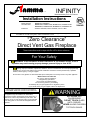
1
Fiamma
INFINITY
LLC.
Manufactured by R-Co for Fiamma
Installation Instructions
Model Numbers:
Stock Numbers:
MQRB5143, MQRB6961
MQRB5143N, MQRB5143NE, MQRB5143LP, MQRB5143LPE
MQRB6961N, MQRB6961NE, MQRB6961LP, MQRB6961LPE
Certified to:
ANSI Z21.50b-2009, CSA 2.22b-2009, CGA 2.17-M91
This appliance is only for use with the type of gas indicated on the rating plate. This appliance is not
convertible for use with other gases, unless a certified kit is used.
“Zero Clearance”
Direct Vent Gas Fireplace
Read this complete manual before beginning installation.
These instructions must be kept with the unit for future reference.
For Your Safety
WARNING: If the information in these instructions is not followed exactly, a fire or
explosion may result causing property damage, personal injury or loss of life.
Warning: Improper installation, adjustment, alteration, service or maintenance can cause property damage,
personal injury or loss of life. Refer to this manual. Installation and service must be performed by a qualified
installer, service agency or the gas supplier.
Do not store or use gasoline or other flammable vapors and liquids in the vicinity of this or any other appliance.
What To Do If You Smell Gas
Do not try to light any appliance.
Extinguish any open flame.
Do not touch any electrical switch.
Do not use any phone in your building.
Immediately call your gas supplier from a neighbour’s phone.
If you cannot reach your gas supplier, call the fire department.
INSTALLER: Leave this manual with the appliance.
CONSUMER: Retain this manual for future reference.
This appliance may be installed in an aftermarket,
permanently located, manufactured home (USA only) or
mobile home, where not prohibited by local codes. This
appliance is only for use with the type(s) of gas indicated
on the rating plate. A conversion kit is supplied with the
appliance.
WARNING
HOT GLASS WILL
CAUSE BURNS
DO NOT TOUCH GLASS
UNTIL COOLED.
NEVER ALLOW CHILDREN
TO TOUCH GLASS.
Table of Contents
Table of Contents ................................................................................................................................................................................... 2
Pre-Installation Questions and Answers................................................................................................................................................. 5
Why does my fireplace or stove give off odour?................................................................................................................................. 5
About the Curing of Paint ................................................................................................................................................................... 5
Noise Coming from the Fireplace? ..................................................................................................................................................... 5
Operating Instructions ............................................................................................................................................................................ 5
Mobile Home/Manufactured Housing Installation ................................................................................................................................... 6
Warnings, Installations and Operations .................................................................................................................................................. 7
Installation Regulations ...................................................................................................................................................................... 7
Operations and Maintenance Instructions .............................................................................................................................................. 8
Installation Requirements for the Commonwealth of Massachusetts ..................................................................................................... 8
MQRB5143: Framing Your Gas Fireplace.............................................................................................................................................. 9
Stand-off Locations ............................................................................................................................................................................ 9
MQRB5143 Locating Your Appliance ................................................................................................................................................... 10
MQRB5143 Fireplace Dimensions ....................................................................................................................................................... 10
MQRB5143 / MQRB6961 Nailing Tab Guide ....................................................................................................................................... 11
MQRB5143 -See Thru Framing............................................................................................................................................................ 12
MQRB5143 Single Sided Framing ....................................................................................................................................................... 14
MQRB5143 Combustible Enclosure Heights........................................................................................................................................ 16
Surround Dimensions MQRB5143 ....................................................................................................................................................... 17
Surround Clearances MQRB5143........................................................................................................................................................ 17
MQRB5143 Facing Material Requirements .......................................................................................................................................... 18
MQRB5143 Mantel Clearances............................................................................................................................................................ 19
Clearance to Combustibles
MQRB5143.................................................................................................................................... 19
MQRB6961: Framing Your Gas Fireplace............................................................................................................................................ 20
Stand-off Locations .......................................................................................................................................................................... 20
MQRB6961 Locating Your Appliance ................................................................................................................................................... 21
MQRB6961 Fireplace Dimensions ....................................................................................................................................................... 21
MQRB5143 / MQRB6961 Nailing Tab Guide ....................................................................................................................................... 22
MQRB6961 See Thru Framing............................................................................................................................................................. 23
MQRB6961 Single Sided Framing ....................................................................................................................................................... 25
MQRB6961 Combustible Enclosure Heights........................................................................................................................................ 27
Surround Dimensions MQRB6961 ....................................................................................................................................................... 28
Surround Clearances MQRB6961........................................................................................................................................................ 28
MQRB6961 Facing Material Requirements .......................................................................................................................................... 29
MQRB6961 Mantel Clearances............................................................................................................................................................ 30
Clearance to Combustibles
MQRB6961................................................................................................................................... 30
MQRB5143BK / MQRB6961BK Back Shield Kit –Single View............................................................................................................ 31
Heat Shield & Firebox Cover ............................................................................................................................................................ 31
Back Liner, False Bottom, and End Panel Installation: ..................................................................................................................... 32
MQRB5143SK / MQRB6961SK (See Thru Kit) Installation ................................................................................................................. 33
MQRB5143 & MQRB6961 Finishing Options ...................................................................................................................................... 34
2
Using Side Fillers ............................................................................................................................................................................. 34
Using other Non-Combustible Materials as Side Fillers (Brick, Tile, Marble, etc.)............................................................................ 34
Using the Optional Surrounds .......................................................................................................................................................... 34
MQRB5143 / MQRB6961 Surround Installation .................................................................................................................................. 35
Optional Additional Screws: Stainless Steel Surrounds ....................................................................................................................... 36
Optional Glass Ember Installation ........................................................................................................................................................ 37
Optional Driftwood & Rock Installation ................................................................................................................................................. 38
Door and Glass Information.................................................................................................................................................................. 39
Glass Cleaning ................................................................................................................................................................................. 39
Glass Replacement .......................................................................................................................................................................... 39
Removal of the Glass Door .............................................................................................................................................................. 39
Spring Replacement ......................................................................................................................................................................... 39
Valve Access Cover Removal .............................................................................................................................................................. 40
MQRB5143 / MQRB6961 Removable Lower Face Panel .................................................................................................................... 40
Installers Note: ................................................................................................................................................................................. 40
Gas Line Installation............................................................................................................................................................................. 41
Gas Specifications............................................................................................................................................................................ 41
Millivolt System, Lighting, and Burner Control ...................................................................................................................................... 42
Troubleshooting the Millivolt Gas Control System ................................................................................................................................ 43
Burner System Maintenance ................................................................................................................................................................ 43
Gas Conversion for Top Convertible Pilot (Series 019065X)................................................................................................................ 44
MQRB5143 Burner Section: Gas Conversion ..................................................................................................................................... 45
MQRB5143 Burner Tube Removal....................................................................................................................................................... 46
MQRB5143 Burner System Removal/Installation Guide ...................................................................................................................... 46
MQRB5143 Moving Valve to Other Side of Fireplace .......................................................................................................................... 47
MQRB6961 Burner Section: Gas Conversion ...................................................................................................................................... 48
MQRB6961 Burner Tube Removal....................................................................................................................................................... 49
MQRB6961 Burner System Removal/Installation Guide ...................................................................................................................... 49
MQRB6961 Moving Valve to Other Side of Fireplace .......................................................................................................................... 50
IPI Electronic Ignition System............................................................................................................................................................... 51
SYSTEM NOTE................................................................................................................................................................................ 51
Remote Receiver Location ................................................................................................................................................................... 51
Electronic Ignition Lighting Instructions ................................................................................................................................................ 52
IPI Electronic Ignition Parts List – Standard System ............................................................................................................................ 53
LK2 Halogen Lamp Kit (MQRB5143) ................................................................................................................................................... 55
LK3 Halogen Lamp Kit (MQRB6961) ................................................................................................................................................... 56
IPI Photos............................................................................................................................................................................................. 57
Bottom of Unit with IPI Module ......................................................................................................................................................... 57
Light Module &IPI Valve ................................................................................................................................................................... 57
Close up View of IPI Module ............................................................................................................................................................ 58
Inside of IPI Module.......................................................................................................................................................................... 58
IPI Valve ........................................................................................................................................................................................... 59
IPI Valve ........................................................................................................................................................................................... 59
3
Millivolt Valve & Light Module........................................................................................................................................................... 60
Millivolt Valve.................................................................................................................................................................................... 60
Venting ................................................................................................................................................................................................. 61
General Vent Installation Information ................................................................................................................................................... 62
Simpson Dura-vent, AmeriVent, and Selkirk Direct Temp ................................................................................................................ 62
Flex Pipe Venting ............................................................................................................................................................................. 62
Termination ...................................................................................................................................................................................... 62
Venting Routes and Components..................................................................................................................................................... 63
Horizontal Vent Table ........................................................................................................................................................................... 64
MQRB5143 Venting Examples............................................................................................................................................................. 65
Wall Thimble and Roof Support........................................................................................................................................................ 65
Installation of Side Wall Venting ........................................................................................................................................................... 66
Venting Straight Up Through Roof ....................................................................................................................................................... 67
Using Flex Bends ............................................................................................................................................................................. 67
Roof Flashing ................................................................................................................................................................................... 67
Flue Restrictor Adjustment ................................................................................................................................................................... 68
MQRB5143 -Parts List.......................................................................................................................................................................... 70
Choose Your View Kit: (Required for each unit) ............................................................................................................................... 70
Infinite Wall Surround-(Covers 50-1/4”W X 19") ............................................................................................................................... 70
Infinite Wall Surround-(Covers 55-3/4"W X 24") ............................................................................................................................... 70
Infinite Porcelain Liners .................................................................................................................................................................... 70
Rocks & Logs ................................................................................................................................................................................... 70
Door Glass ....................................................................................................................................................................................... 70
Replacement Burner Assembly ........................................................................................................................................................ 71
Conversion Kit .................................................................................................................................................................................. 71
Venting Accessories ......................................................................................................................................................................... 71
MQRB6961 -Parts List.......................................................................................................................................................................... 72
Choose Your View Kit: (Required for each unit) ............................................................................................................................... 72
Infinite Wall Surround-(Covers 69-1/8”W X 19") ............................................................................................................................... 72
Infinite Wall Surround-(Covers 74-7/8"W X 24") ............................................................................................................................... 72
Infinite Porcelain Liners .................................................................................................................................................................... 72
Rocks & Logs ................................................................................................................................................................................... 72
Door Glass ....................................................................................................................................................................................... 72
Replacement Burner Assembly ........................................................................................................................................................ 73
Conversion Kit .................................................................................................................................................................................. 73
Venting Accessories ......................................................................................................................................................................... 73
Common Parts for MQRB5143 and MQRB6961 .................................................................................................................................. 74
Accessories ...................................................................................................................................................................................... 74
Millivolt Remotes .............................................................................................................................................................................. 74
IPI Remotes...................................................................................................................................................................................... 74
Valve System Parts .......................................................................................................................................................................... 74
Miscellaneous Parts ......................................................................................................................................................................... 74
4
Pre-Installation Questions and Answers
Why does my fireplace or stove give off odour?
It is normal for your fireplace to give off some odour. This is due to the curing of paint, adhesives, silicones and any
undetected oil from the manufacturing process as well as the finishing materials used with the installation (e.g. marble, tile
and the adhesives used to adhere these products to the walls can react with heat and cause odours).
It is recommended that you burn your gas fireplace or stove for a minimum of four hours at a time with the fan off after the
curing of the paint has been completed. These odours can last upward to 40 hours of burn time. Keep burning at a minimum
of four hours per use until odours dissipate.
About the Curing of Paint
Your stove or fireplace has been painted with the highest quality silicone stove paint .This paint dries quickly (15-20
minutes) when first applied at the factory. However, due to the high temperature silicone components, the paint will cure
when heat is applied to the appliance as it is first used.
The following information applies to the curing process to get the paint fully hard and durable:
Fire the appliance four successive times for 10 minutes each firing and a 5 minute cool down between each. Be aware
during log and firebox paint curing that a white deposit may be developing on the inside of the glass doors. It is important to
remove this white deposit from the glass doors with an appropriate cleaner (such as Windex or a commercial fireplace glass
cleaner) to prevent build-up.
•
Babies, small children, pregnant women, and pets should leave the area during the cure phase.
•
Ventilate well, open doors and windows.
•
Do not touch during curing.
Noise Coming from the Fireplace?
•
Noise caused by metal expanding and contracting as it heats up and cools down, similar to the sound produced by a
furnace or heating duct. This noise does not affect the operation or longevity of your fireplace.
Operating Instructions
1.
Be sure to read and understand all the instructions in this manual before operation of appliance.
2.
Ensure all wiring is correct and properly enclosed to prevent possible shock.
3.
Check for gas leaks.
4.
Make sure the glass door is properly installed before operation. Never operate the appliance with the glass door removed.
5.
Make sure venting and termination cap are installed and unobstructed.
6.
If brick or porcelain liners are used, ensure they are installed.
7.
Verify that the pilot can be seen when lighting the appliance. If not, the log or rock placement is incorrect.
8.
If the unit is turned off, you must wait a minimum of 60 seconds before re-lighting it.
5
Mobile Home/Manufactured Housing Installation
This Direct Vent System Appliance must be installed in accordance with the manufacturer’s installation instructions and the
Manufactured Home Construction and Safety Standard Title 24 CFR, Part 3280, or the current Standard for Fire Safety
Criteria for Manufactured Home Installations, Sites, and Communities ANSI/NFPA 501A, and with CAN/CSA Z240 MH
Mobile Home Standard in Canada.
Figure 1 - Mobile Home Installation.
THE MQRB5143N, MQRB5143LP, MQRB6961N, AND MQRB6961LP MAY BE INSTALLED IN MANUFACTURED
(MOBILE) HOMES AFTER FIRST SALE IN THE USA. IN CANADA THE MQRB5143N, MQRB5143LP, MQRB6961N,
AND MQRB6961LP MAY BE INSTALLED IN MANUFACTURED (MOBILE) HOMES.
Please follow the current ANSI/NFPA 70 National Electrical Code in the USA and CAN/CSA C22.1 Canadian National
Electrical Code in Canada.
An appliance must be grounded to the steel chassis of the home with 8ga copper wire using a serrated or star washer to
penetrate paint or protective coating to insure grounding.
Use carriage bolt at the attachment point (see diagram above) to secure the appliance to the floor.
Warning: Do not compromise the structural integrity of the manufactured home
wall floor or ceiling during installation of appliance or venting.
For required venting components see venting installation in appropriate section of this manual.
Certified for installation in a bedroom or bedsitting room. In Canada must be installed
with listed millivolt thermostat. In USA see local codes.
6
Warnings, Installations and Operations
Installation Regulations
This gas appliance must be installed by a qualified installer in accordance with local building codes, or in the absence of
local codes, with the current CAN/CGA-B149.1 or .2 Installation Code (in Canada) or the current National Fuel Gas Code
Z223.1 when installed in the United States.
This appliance, when installed, must be electrically connected and grounded in accordance with local codes, or in the
absence of local codes, with the current CSA C22.1 Canadian Electrical Code or with the national Electrical Code;
ANSI/NFPA 70-1987 when installed in the United States.
WARNING
FOR SAFE INSTALLATION AND OPERATION OF YOUR GAS FIREPLACE PLEASE NOTE THE FOLLOWING:
1.
2.
3.
4.
5.
6.
7.
8.
9.
10.
11.
12.
13.
14.
15.
16.
17.
18.
19.
20.
21.
22.
23.
24.
25.
Do not clean when the glass is hot.
Do not use abrasive cleaners.
Using a substitute glass will void all product
warranties.
HOT GLASS WILL
For safe operation, glass doors must be
closed.
CAUSE BURNS
When purging the gas line, the glass front
DO NOT TOUCH GLASS
must be removed.
UNTIL COOLED.
Do not strike or abuse glass. Take care to
NEVER ALLOW CHILDREN
avoid breakage.
TO TOUCH GLASS.
Do not alter gas orifice.
No substitute materials may be used other
than factory supplied components.
This appliance gives off high temperatures and should be located out of heavy traffic areas and away from furniture and
draperies.
Children and adults should be alerted to the hazards of the high surface temperatures of this appliance and should stay
away to avoid burns or ignition of clothing.
Young children should be carefully supervised when they are in the same room as the appliance. Toddlers, young children
and others may be susceptible to accidental contact burns. A physical barrier is recommended if there are at risk individuals
in the house. To restrict access to a fireplace or stove, install an adjustable safety gate to keep toddlers, young children and
other at risk individuals out of the room and away from hot surfaces.
Under no circumstances should any solid fuels (wood, paper) be used in this appliance.
Under no circumstances should this appliance be modified. Any parts that have to be removed for servicing should be
replaced prior to operating this appliance.
Any safety screen or guard removed for servicing an appliance must be replaced prior to operating the appliance.
Installation and repair should be done by a qualified service person. The appliance should be inspected before use and at
least annually by a professional service person. More frequent cleaning may be required due to excessive lint from
carpeting, bedding material, et cetera. It is imperative that control compartments, burners and circulating air passageways of
the appliance be kept clean. Make sure that the gas valve and pilot light are turned off before you attempt to clean this unit.
Clothing or other flammable material should not be placed on or near the appliance. This appliance should not be used as a
drying rack for clothing nor should Christmas stockings or decorations be hung from it.
Do not use this heater if any part has been under water. Immediately call a qualified service technician to inspect the heater
and to replace any part of the control system and any gas control which has been under water.
Do not operate appliance unless completely installed as per installation instructions.
Failure to position the parts in accordance with these diagrams or failure to use only parts specifically approved with this
appliance may result in property damage or personal injury.
Do not operate appliance with the glass front removed, cracked or broken. Replacement of the glass should be done by a
licensed or qualified service person.
The front of the fireplace gives off high temperatures that could ignite combustible material which is kept close to the front of
the unit.
Ensure that power to the Fireplace is turned off before servicing.
Do not operate this Fireplace without the glass front or with a broken glass.
Improper installation, adjustment, alteration, service or maintenance can cause injury or property damage. Refer to the
owner’s information manual provided with this appliance. For assistance or additional information consult a qualified
installer, service agency, or the gas supplier.
Operation of this appliance when not connected to a properly installed and maintained venting system or tampering with the
blocked vent shutoff system can result in carbon monoxide (CO) poisoning and possible death.
WARNING
7
•
Gas fired appliances may be used only for supplemental heat and/or decorative purposes and under no circumstances shall they
provide a primary heat source.
•
This appliance must not be connected to a chimney flue serving a separate solid-fuel burning appliance.
NOTE: It is recommended that a Carbon Monoxide (CO) Detector be installed in or near bedrooms and on all levels of your
home. Place a detector about 15ft [4.5m] outside the room that houses your gas appliance.
Certified for installation in a bedroom or bed/sitting room. In Canada must be installed with listed millivolt thermostat. In USA see
local codes.
Operations and Maintenance Instructions
•
•
•
•
For safe installation and operation note the following:
The Burner/Log Assembly has been engineered and permanently adjusted for proper flame control.
Periodically remove the logs from the grate assembly and vacuum any loose particles from the grate and burner areas. See Log
Placement page to remove logs. Vacuum burner parts and replace logs.
Never use your gas fireplace as a cooking device.
Label all wires prior to disconnection when servicing controls. Wiring errors can cause improper and dangerous operation. Verify
proper operation after servicing.
Installation Requirements for the Commonwealth of Massachusetts
1.
2.
In the Commonwealth of Massachusetts, the installer or service agent shall be a plumber or gas fitter licensed by the
Commonwealth.
When installed in the Commonwealth of Massachusetts or where applicable codes; the unit shall be installed with a CO
detector per the requirements listed below.
For direct-vent appliances, mechanical-vent heating appliances or domestic hot water equipment, where the bottom of the vent
terminal and the air intake is installed below four feet above grade the following requirements must be satisfied:
A. If there is not one already present, on each floor level where there are bedroom(s), a carbon monoxide detector and
alarm shall be placed in the living area outside the bedroom(s). The carbon monoxide detector shall comply with NFPA
720 (2005 Edition).
B. A carbon monoxide detector shall be located in the room that houses the appliance or equipment and shall:
•
Be powered by the same electrical circuit as the appliance or equipment such that only one service switch services
both the appliance and the carbon monoxide detector;
•
Have battery back-up power;
•
Meet ANSI./UL 2034 Standards and comply with NFPA 720 (2005 Edition); and
•
Have been approved and listed by a Nationally Recognized Testing Laboratory as recognized under 527 CMR.
C.
A Product-approved vent terminal must be used, and if applicable, a Product-approved air intake must be used.
Installation shall be in strict compliance with the manufacturer’s instructions. A copy of the installation instructions shall
remain with the appliance or equipment at the completion of the installation.
D.
A metal or plastic identification plate shall be mounted at the exterior of the building, four feet directly above the location
of vent terminal. The plate shall be of sufficient size to be easily read from a distance of eight feet away, and read “Gas
Vent Directly Below”.
For direct-vent appliances, mechanical-vent heating appliances or domestic hot water equipment where the bottom of the vent
terminal and the air intake is installed above four feet above grade the following requirements must be satisfied:
A.
If there is not one already present, on each floor level where there are bedroom(s), a carbon monoxide detector and
alarm shall be placed in the living area outside the bedroom(s). The carbon monoxide detector shall comply with NFPA
720 (2005 Edition).
B. A carbon monoxide detector shall:
•
Be located in the room that houses the appliance or equipment;
•
•
Be either hard-wired or battery powered or both; and
Shall comply with NFPA 720 (2005 Edition).
A Product-approved vent terminal must be used, and if applicable, a Product-approved air intake must be used. Installation
shall be in strict compliance with the manufacturer instructions. A copy of the installation instructions shall remain with the
appliance or equipment at the completion of the installation.
For the state of Massachusetts a T-handle gas shut-off valve must be used on a gas appliance. This T-handle gas shut-off valve must be
listed and approved by the state of Massachusetts. This is in reference to the state of Massachusetts state code CMR238.
8
MQRB5143:
Framing Your Gas Fireplace
This section is intended for qualified installers only. Before beginning, make note of where the gas and electrical accesses
are located on the unit. This will streamline the construction process. Furthermore, familiarize yourself with the venting and
clearance requirements (see Venting section) for this appliance. Failure to comply with those requirements can seriously
compromise the safety and operation of the fireplace.
Specifications
1. Cold climate installation recommendation: When installing this fireplace against non insulated exterior wall or chase,
it is recommended that the outer walls be insulated to conform to applicable insulation codes. Drywall & vapor barrier
must be installed over insulation to prevent contact of insulation and unit.
2. Choose fireplace location and frame in accordance with the fireplace framing dimensions specified (see framing
diagrams).
3. Drywall or other combustible material can extend up to the Drywall Stops located on the sides of the unit, and up to
the bottom and top.
4. When installing horizontal with a 90 degree bend, maintain a minimum of five inches [5"] above the bend with the
Wall Thimble Shield [Z57WTS] in enclosures below seventy-two inches [72”]. See MQRB5143 Combustible
Enclosure Heights page.
5. A Hearth is not required for this unit.
Vertical Venting in Cold Climates
In cold climate conditions where temperatures go below -10 degrees Celsius or 14 degrees Fahrenheit, we recommend
that the chase be insulated and where the vent pipe enters into the attic space that the pipe be wrapped with an
insulated Mylar sleeve. This will increase the temperature of the vent and help the appliance to vent properly in cold
weather conditions.
It is also important in vertical vented direct vent appliances that the appliance be operated daily during the winter months
as this will help stop the termination from freezing up. We recommend using a thermostat set at room temperature to
allow the unit to cycle.
For IPI models it may be necessary to set the appliance to Standing Pilot mode to maintain heat in the cavity. The
purpose of this procedure is to prevent cold air from penetrating the chimney and then onto the living space. Therefore,
when the internal temperature is slightly elevated the fireplace is able to freely exhaust its combustion and hence making
it easier to startup.
Certified for installation in a bedroom or bedsitting room. In Canada must be installed
with listed millivolt thermostat. In USA see local codes.
Stand-off Locations
Make note of where the stand-off locations are. These stand-offs are provided as indicators to illustrate the
boundaries for framing. Therefore, no framing material is permitted to extend beyond these stand-offs.
9
MQRB5143 Locating Your Appliance
All units are Factory Set for a Left Hand Burner System. Right Hand Burner System Requires Valve to be relocated to right
side of unit.
MQRB5143 Fireplace Dimensions
10
MQRB5143 / MQRB6961 Nailing Tab Guide
[Qty] 2 Nailing Tabs are
located on each corner of the
fireplace.
The Nailing Tabs on the MQRB5143 or MQRB6961 can be used in two ways:
Framing Flush with Face of Fireplace -Fireplace to be covered
with Non-Combustibles (e.g. Concrete Board) for Flat Wall
appearance.
1/2” Drywall Flush with Face of Fireplace –Fireplace and
Combustible Wall to be covered with Non-Combustible
Materials (e.g. Tile around Fireplace).
Note: If using Optional Surround, Maximum Thickness for
Non-Combustible Material is 3/4”.
Note: If using Optional Surround, Maximum Thickness for NonCombustible Material is 3/4”.
[Steel Stud Framing Shown.]
11
MQRB5143 -See Thru Framing
An MQRB5143SK Kit is required for a See Thru Installation.
Before you begin Framing- Determine for both sides whether the Wall Surface will be flush with the face of the
fireplace (Fireplace and wall to be covered with Non-Combustibles, such as tile), or the
Framing will be flush with the face of the fireplace (Flat Wall appearance).
Note: If using Optional Surround, Maximum Thickness for Non-Combustible Material is 3/4”.
Framing Style shown is for illustration purposes only.
This structure is NOT load bearing.
*15-3/8” Dimension is for Wall Surface Flush with Unit on Both Sides.
Add 1/2” to this Dimension for each side where a non-combustible wall
surface will cover the unit (See Nailing Tab Guide Page Also).
15-3/8”*
(Continued)
12
Wall Surface Flush With Face of Fireplace
Framing Flush With Face of Fireplace
Note: If using Optional Surround, Maximum Thickness for Non-Combustible Material is 3/4”.
[Steel Stud Framing Shown.]
*See the “Nailing Tab Guide” and “MQRB5143SK / MQRB6961SK” pages before placing unit into the framed opening.*
13
MQRB5143 Single Sided Framing
An MQRB5143BK Kit is required for a Single Sided Installation.
Before you begin Framing- Determine whether the Wall Surface will be flush with the face of the fireplace (Fireplace
and wall to be covered with Non-Combustibles, such as tile), or the Framing will be flush
with the face of the fireplace (Flat Wall appearance).
Note: If using optional surround, maximum thickness for non-combustible material is 3/4”.
Framing Style shown is for illustration purposes only.
This structure is NOT load bearing.
* 17” Min. Dimension is for Wall Surface Flush with fireplace.
Add 1/2” to this Dimension where a non-combustible wall surface will
cover the unit (See Nailing Tab Guide Page also).
17” Min. *
(Continued)
14
Wall Surface Flush With Face of Fireplace
Framing Flush With Face of Fireplace
Note: If using Optional Surround, Maximum Thickness for Non-Combustible Material is 3/4”.
[Steel Stud Framing Shown.]
See the “Nailing Tab Guide” and “MQRB5143BK / MQRB6961BK” pages before placing unit into the framed opening.
15
MQRB5143 Combustible Enclosure Heights
Cold Climate Recommendation
When installing this fireplace against an exterior wall or chase, it is recommended that the outer walls be
insulated to conform to applicable insulation codes. Drywall must be installed over vapor barrier and
insulation material to prevent direct contact with the appliance.
See Thru or Single Sided Installation
[Steel Stud Framing Shown.]
Single Side Installation Only
[Steel Stud Framing Shown.]
MQRB5143
The Wall Thimble Shield Z57WTS is required in
All Enclosures below 72” [Seventy-Two Inches].
Place Wall Thimble Shield Z57WTS against the
Wall Thimble Immediately above the Vent. Install
the Wall Thimble Shield using [3] DT Screws.
16
Surround Dimensions MQRB5143
•
•
•
The Surround Frames are 1” thick, with a 3/4” space behind the frame.
When using Surrounds, Maximum Thickness for Non-Combustible Facing Materials is 3/4”.
The Fireplace may be covered up to within 1/2” of the Fireplace Opening with non-combustible materials.
Surround Clearances MQRB5143
17
MQRB5143 Facing Material Requirements
These specifications are the same for all Models (5143N, 5143NE, 5143LP, 5143LPE).
Note: If using Optional Surround, See Surround Clearances Section.
[Steel Stud Framing Shown.]
Note: Do not drive excessively long screws into the face of the unit as internal parts may be damaged.
Steel Stud Framing Shown.
18
MQRB5143 Mantel Clearances
Before installing any mantels it is important to determine the combustibility of its
material(s). There are two types of mantels to consider: Combustible and NonCombustible.
A Combustible Mantel is one that consists of material(s) that may discolor,
combust, or lose its integrity in the presence of heat. These types of mantels
must strictly conform to the dimensional requirements shown below.
-Combustible Objects on NonCombustible Mantel WarningCombustible objects must not be placed
on a Non-combustible Mantel unless the
mantel meets the dimensional
requirements for a Combustible Mantel.
Refer below to determine whether your
mantel conforms to the requirements of
a Combustible Mantel.
Conversely, a Non-Combustible Mantel is one that is constructed with material(s)
that will not combust. Check your local codes and regulations to determine whether your mantel is Combustible or Non-Combustible.
The advantage to Non-Combustible Mantels is that it may extend right up to the tile lip of the fireplace. Combustible mantels must
adhere to the dimensional restrictions shown below.
[Steel Stud Framing Shown.]
Mantel Dimensions are
from front face or NonCombustible Facing
Materials covering
fireplace.
Clearance to Combustibles
MQRB5143
Back
0” [0cm]
Side (from Stand-offs)
0” [0cm]
Floor*
0” [0cm]
Minimum Ceiling Height (from bottom of fireplace)
60”
Top (from Stand-offs)
Top of 90° Bend under 72” Enclosure
0” [0cm]
5” (With Wall Thimble Shield
[Z57WTS]) All Vent Systems
Top of 90° Bend over 72” Enclosure
4” All Vent Systems
Top of Horizontal Pipe
2” All Vent Systems
Side & Bottom of Horizontal Pipe
1” All Vent Systems
Vertical Vent Pipe
1” All Vent Systems
Vertical Vent Pipe
1” Simpson / AmeriVent
*Note: If appliance is installed
directly on carpeting or other
combustible material other than
wood flooring, a metal or wood
panel extending the full width
and depth of the appliance must
be used. Carpet may extend 1
inch above the floor of the
appliance.
/ Selkirk Direct Temp Systems
19
MQRB6961: Framing Your Gas Fireplace
This section is intended for qualified installers only. Before beginning, make note of where the gas and electrical accesses
are located on the unit. This will streamline the construction process. Furthermore, familiarize yourself with the venting and
clearance requirements (see Venting section) for this appliance. Failure to comply with those requirements can seriously
compromise the safety and operation of the fireplace.
1.
2.
3.
4.
5.
Specifications
Cold climate installation recommendation: When installing this fireplace against non insulated exterior wall or chase,
it is recommended that the outer walls be insulated to conform to applicable insulation codes. Drywall & vapor
barrier must be installed over insulation to prevent contact of insulation and unit.
Choose fireplace location and frame in accordance with the fireplace framing dimensions specified (see framing
diagrams).
Drywall or other combustible material can extend up to the Drywall Stops located on the sides of the unit, and up to
the bottom and top.
When installing horizontal with a 90 degree bend maintain a minimum of six and one half inches [6-1/2”] for
MQRB6961 above the bend with the Wall Thimble Shield [Z57WTS] in enclosures below seventy-eight inches [78”].
See MQRB6961 Combustible Enclosure Heights page.
A Hearth is not required for this unit.
Vertical Venting in Cold Climates
In cold climate conditions where temperatures go below -10 degrees Celsius or 14 degrees Fahrenheit, we recommend
that the chase be insulated and where the vent pipe enters into the attic space that the pipe be wrapped with an
insulated Mylar sleeve. This will increase the temperature of the vent and help the appliance to vent properly in cold
weather conditions.
It is also important in vertical vented direct vent appliances that the appliance be operated daily during the winter months
as this will help stop the termination from freezing up. We recommend using a thermostat set at room temperature to
allow the unit to cycle.
For IPI models it may be necessary to set the appliance to Standing Pilot mode to maintain heat in the cavity. The
purpose of this procedure is to prevent cold air from penetrating the chimney and then onto the living space. Therefore,
when the internal temperature is slightly elevated the fireplace is able to freely exhaust its combustion and hence making
it easier to startup.
Certified for installation in a bedroom or bedsitting room. In Canada must be installed
with listed millivolt thermostat. In USA see local codes.
Stand-off Locations
Make note of where the stand-off locations are. These stand-offs are provided as indicators to illustrate the
boundaries for framing. Therefore, no framing material is permitted to extend beyond these stand-offs.
20
MQRB6961 Locating Your Appliance
All units are Factory Set for a Left Hand Burner System. Right Hand Burner System Requires Valve to be relocated to right
side of unit.
MQRB6961 Fireplace Dimensions
21
MQRB5143 / MQRB6961 Nailing Tab Guide
[Qty] 2 Nailing Tabs are
located on each corner of the
fireplace.
The Nailing Tabs on the MQRB5143 or MQRB6961 can be used in two ways:
Framing Flush with Face of Fireplace -Fireplace to be covered
with Non-Combustibles (e.g. Concrete Board) for Flat Wall
appearance.
1/2” Drywall Flush with Face of Fireplace –Fireplace and
Combustible Wall to be covered with Non-Combustible
Materials (e.g. Tile around Fireplace).
Note: If using Optional Surround, Maximum Thickness for
Non-Combustible Material is 3/4”.
Note: If using Optional Surround, Maximum Thickness for NonCombustible Material is 3/4”.
[Steel Stud Framing Shown.]
22
MQRB6961 See Thru Framing
MQRB6961SK Kit is required for a See Thru Installation.
Before you begin Framing- Determine whether the Wall Surface will be flush with the face of the fireplace (Fireplace
and wall to be covered with Non-Combustibles, such as tile), or the Framing will be flush
with the face of the fireplace (Flat Wall appearance).
Note: If using optional surround, maximum thickness for non-combustible material is 3/4”.
Framed Opening 71-1/2” x 45-1/2”
Framing style shown is for illustration purposes only.
This structure is NOT load bearing.
Fireplace vent MUST maintain min. 1” clearance from combustible (Wood) framing.
However, if steel stud framing is used, 1” vent clearance is not required.
Also refer to these sections:
Clearance to Combustibles
Enclosure Heights
Venting
(Continued)
23
Wall Surface Flush With Face of Fireplace
Framing Flush With Face of Fireplace
20-3/8”
19-3/8”
Note: If using Optional Surround, Maximum Thickness for Non-Combustible Material is 3/4”.
[Steel Stud Framing Shown.]
See the “Nailing Tab Guide” and “MQRB5143SK / MQRB6961SK” pages before placing unit into the framed opening.
24
MQRB6961 Single Sided Framing
An MQRB6961BK Kit is required for a Single Sided Installation.
Before you begin Framing- Determine whether the Wall Surface will be flush with the face of the fireplace (Fireplace
and wall to be covered with Non-Combustibles, such as tile), or the Framing will be flush
with the face of the fireplace (Flat Wall appearance).
Note: If using optional surround, maximum thickness for non-combustible material is 3/4”.
Framed Opening 71-1/2” x 45-1/2”
Framing Style shown is for illustration purposes only.
This structure is NOT load bearing.
*21” Min. Dimension is for Wall Surface Flush with fireplace.
Add 1/2” to this Dimension where a non-combustible wall surface will
cover the unit (See Nailing Tab Guide Page also).
21” Min.*
Fireplace vent MUST maintain min. 1” clearance from combustible (Wood) framing.
However, if steel stud framing is used, 1” vent clearance is not required.
Also refer to these sections:
Clearance to Combustibles
Enclosure Heights
Venting
(Continued)
25
Wall Surface Flush With Face of Fireplace
Framing Flush With Face of Fireplace
21-1/4”
20-3/4”
Note: If using Optional Surround, Maximum Thickness for Non-Combustible Material is 3/4”.
[Steel Stud Framing Shown.]
*See the “Nailing Tab Guide” and “MQRB5143BK / MQRB6961BK” pages before placing unit into the framed opening.*
26
MQRB6961 Combustible Enclosure Heights
Cold Climate Recommendation
When installing this fireplace against an exterior wall or chase, it is recommended that the outer walls be
insulated to conform to applicable insulation codes. Drywall must be installed over vapor barrier and
insulation material to prevent direct contact with the appliance.
See Thru or Single Sided Installation
[Steel Stud Framing Shown.]
Single Side Installation Only
[Steel Stud Framing Shown.]
MQRB6961:
The Wall Thimble Shield Z57WTS is required in
All Enclosures below 78” [Seventy-Eight Inches].
Place Wall Thimble Shield Z57WTS against the
Wall Thimble Immediately above the Vent. Install
the Wall Thimble Shield using [3] DT Screws.
27
Surround Dimensions MQRB6961
•
•
•
The Surround Frames are 1” thick, with a 3/4” space behind the frame.
When using Surrounds, Maximum Thickness for Non-Combustible Facing Materials is 3/4”.
The Fireplace may be covered up to within 1/2” of the Fireplace Opening with non-combustible materials.
Surround Clearances MQRB6961
28
MQRB6961 Facing Material Requirements
These specifications are the same for all Models (6961N, 6961NE, 6961LP, 6961LPE).
Note: If using Optional Surround, MQRB6961 See Surround Clearances Section.
[Steel Stud Framing Shown.]
Note: Do not drive excessively long screws into the face of the unit as internal parts may be damaged.
Steel Stud Framing Shown.
29
MQRB6961 Mantel Clearances
Before installing any mantels it is important to determine the combustibility of its
material(s). There are two types of mantels to consider: Combustible and NonCombustible.
A Combustible Mantel is one that consists of material(s) that may discolor,
combust, or lose its integrity in the presence of heat. These types of mantels
must strictly conform to the dimensional requirements shown below.
-Combustible Objects on NonCombustible Mantel WarningCombustible objects must not be placed
on a Non-combustible Mantel unless the
mantel meets the dimensional
requirements for a Combustible Mantel.
Refer below to determine whether your
mantel conforms to the requirements of
a Combustible Mantel.
Conversely, a Non-Combustible Mantel is one that is constructed with material(s)
that will not combust. Check your local codes and regulations to determine whether your mantel is Combustible or Non-Combustible.
The advantage to Non-Combustible Mantels is that it may extend right up to the tile lip of the fireplace. Combustible mantels must
adhere to the dimensional restrictions shown below.
[Steel Stud Framing Shown.]
Mantel Dimensions are
from front face or NonCombustible Facing
Materials covering
fireplace.
Clearance to Combustibles
MQRB6961
Back
Side (from Stand-offs)
Floor*
Minimum Ceiling Height (from bottom of fireplace)
Top (from Stand-offs)
Top of 90° Bend under 78” Enclosure
Top of 90° Bend over 78” Enclosure
Top of Horizontal Pipe
Side & Bottom of Horizontal Pipe
Vertical Vent Pipe
Vertical Vent Pipe
0” [0cm]
0” [0cm]
0” [0cm]
64”Vertical
68”Horizontal (See MQRB6961
Combustible Enclosure Heights page)
0” [0cm]
6-1/2” (With Wall Thimble Shield
[Z57WTS]) All Vent Systems
6-1/2” All Vent Systems
2” All Vent Systems
1” All Vent Systems
1” All Vent Systems
1” Simpson / AmeriVent
/ Selkirk Direct Temp Systems
*Note: If appliance is installed directly on carpeting or other combustible material other than wood flooring, a metal or
wood panel extending the full width and depth of the appliance must be used. Carpet may extend 1 inch above the
floor of the appliance.
30
MQRB5143BK / MQRB6961BK Back Shield Kit –Single View
*This Kit must be opened before unit is installed into Framing (See “Single Sided Framing” pages of this Manual).
Warning: Failure to position the parts in accordance with these diagrams or failure to use only parts
specifically approved with this appliance may result in property damage or personal injury.
•
•
•
•
•
•
Contents of Kit:
Firebox Cover
Heat Shield Assembly
Back Liner
False Bottom
Small Tube Millpac
(Qty)45- DT Screws
Heat Shield & Firebox Cover
Before placing fireplace into framed
opening, you must install the Firebox
Cover and the Heat Shield Assembly
onto the back of the unit. The
remaining parts of this kit can be
installed after the fireplace is installed
into the framed opening.
Do Not Overtighten or Strip Screws!
Apply a small bead of Millpac to
Firebox Cover Gasket before
Installation.
(Continued…)
31
Back Liner, False
Bottom, and End
Panel Installation:
1.
Remove Liner Clips from
the inside of the Firebox.
2.
Place the Back Liner into
the Firebox with bends
facing the Rear Firebox
Cover.
3.
Next install the False
Bottom with larger
Dimension to Front Glass
Opening (See Right),
and secure it using DT
screws into the mounting
tabs on the Burner Tube.
4.
Place End Panels on top
of the False Bottom and
tilt into place at either end
of the Firebox. Replace
the Liner Clips.
5.
Place the bottom of the
door into the door
retainer slot, and then
secure the door with the
top latches (See Door
and Glass Information in
manual if more
information is required).
6.
To locate Valve Access
Cover, engage the tabs
into the slots in the
Access Panel Brackets
on the Fireplace.
MQRB5143 Dimensions
MQRB6961 Dimensions
Smaller Dimension goes
Behind the Burner Tube.
Larger Dimension goes
to Front Glass Opening.
32
MQRB5143SK / MQRB6961SK (See Thru Kit) Installation
This basic Kit is required for See Thru installations.
Note: To cover the Side Fillers with non-combustible materials, they must be installed before Facing materials are applied.
Warning: Failure to position the parts in accordance with these diagrams or failure to use only parts
specifically approved with this appliance may result in property damage or personal injury.
Components:
[2ea.] Side Fillers
Valve Access Cover
Glass Door c/w Glass
See Thru False Bottom
[4ea.] #6 Black Screws
[8ea.] ¼” DT Screws
13-1/8” for MQRB6961
Installation Procedure:
1.
Side Fillers
Place Side Filler onto Side of
Fireplace opening. Attach with [2]
#6 Screws provided. Repeat for
the other side.
2.
False Bottom
Insert False Bottom into Fireplace.
Fasten the False Bottom to the
Burner Assembly using the DT
Screws provided.
3.
End Panels
Remove the Liner Retainer Clips
in the Firebox Top. Place End
Panels into Firebox on top of the
False Bottom and tilt into place at
either end of the Firebox. Replace
the Liner Retainer Clips.
13-1/8” for MQRB6961
4.
Door
Place the bottom of the door into
the door retainer slot, and then
secure the door with the top
latches (See Door and Glass
Information in manual if more
information is required).
5.
Valve Access Cover
To locate Valve Access Cover,
engage the tabs into the slots in
the Access Panel Brackets on the
Fireplace.
33
MQRB5143 & MQRB6961 Finishing Options
Using Side
Fillers
The Side Fillers are
located at each side of
the door. They are
provided to give a
continuous surface up
to the opening of the
fireplace door.
Using other Non-Combustible Materials as Side Fillers (Brick, Tile, Marble, etc.)
Non-Combustible
facing materials, such
as brick or tile may be
used in place of the
Side Fillers- so long as
the total amount of
material applied is not
thicker than 1-1/2” on
the inside of the
fireplace opening. This
will allow for removal of
the Glass Door &
Access Panel.
Using the Optional Surrounds
The Surround Frames are
1-1/2” & 4” wide and 1”
thick, with a ¾” space
behind the frame.
The Fireplace may be
covered up to within ½”
of the opening with noncombustible materials up
to ¾” thick.
The Surround Side Fillers
taper in toward the door
opening. The Surround
Access Panel is tapered to
match the angle of the Side
Fillers.
34
MQRB5143 / MQRB6961 Surround Installation
The Surround Kits for the MQRB5143 are available in 3 different finishes:
MQRB5143
Surround Kits:
MQRB6961
Small [1-1/2”]
Large [4”]
Small [1-1/2”]
Large [4”]
MQRB5019SBL
MQRB5019SSS
MQRB5019SPW
MQRB5624SBL
MQRB5624SSS
MQRB5624SPW
MQRB6919SBL
MQRB6919SSS
MQRB6919SPW
MQRB6924SBL
MQRB6924SSS
MQRB6924SPW
-Black
-Stainless Steel
-Pewter
Each kit contains:
(Qty-1) Surround Frame
(Qty-2) Surround Side Fillers
(Qty-1) Surround Access Cover
(Qty-8) #6 Self Tapping Screws
The Surround Frames are 1” thick, with a ¾” space behind the frame. The Fireplace may be covered
up to within ½” of the opening with non-combustible materials.
Surround Installation:
1.
Note: Original Side Fillers & Valve
Access Cover will not be used.
2.
The Lower Front Face Panel must
be installed on the fireplace before
surround can be installed.
3.
Remove Glass Door from
fireplace.
4.
Hook lower ledge of Surround
Frame onto the Lower Front Face
Panel of the fireplace. With top of
Frame tilted outward, slide Side
Fillers behind Surround Frame.
5.
Push Surround Frame into place
and install using the existing screw
holes in the tile lip. Front Edge of
the Side Filler must rest between
Surround Frame and Fireplace
[see fig.2].
6.
Fasten the Side Fillers to the
fireplace using the two [2] existing
holes on either side of the firebox
opening.
7.
Replace the Glass Door and put
the new Valve Access Cover into
place with angled ends to match
Side Fillers.
*For Stainless Steel Surrounds see next page.
NOTES: Cotton gloves must be worn to protect the finish during installation and handling.
All hand and finger marks must be cleaned off with a soft cloth and light detergent prior to applying heat to the unit.
Stainless panels may discolor a little during normal operation. This is normal and should not be considered a defect.
35
Optional Additional Screws: Stainless Steel Surrounds
Two additional screws may be added to MQRB5019SS and MQRB5624SS to counteract heat distortion.
Directions:
1. Install Surround normally as per Instructions.
2. Drill a pilot hole through the unused slot in each corner of the inner top of the surround.
3. Insert Screw.
36
Optional Glass Ember Installation
If you wish to use this media evenly spread the glass embers onto the false bottom and burner.
Ensure the glass embers do not excessively overlap as this will affect the flame pattern.
Use care when placing glass embers near the pilot area so as not block or have the glass fall over the
crossover holes from the pilot to the burner, as delayed ignition can occur.
The following types of glass are approved (Use of any other type other than listed below can alter the
performance of the unit and is not covered under warranty.):
Note: Use only 1/2” glass material on the burner.
• ½” Ember Glass Material from American Fireglass.
Maximum amount for MQRB5143: Natural Gas is 10 lbs, Propane units 5 lbs.
Maximum amount for MQRB6961: Natural Gas is 20 lbs, Propane units 10 lbs.
• Liquid Glass from Firegear.
Maximum amount for MQRB5143: Natural gas is 10 lbs, not recommended for Propane appliances.
Maximum amount for MQRB6961: Natural gas is 20 lbs, not recommended for Propane appliances.
Discoloration of glass media may occur if placed on the burner, this is not covered under warranty.
37
Optional Driftwood & Rock Installation
The following Driftwood and Decorative Rock kits are available for the Infinite Series.
Model
MQRB5143
MQRB6961
MQRB5143 or MQRB6961
MQRB5143 or MQRB6961
Part Number
MQRBD1
MQRBD2
MQRock2
MQRock3
Description
Drift Wood (x4) and Rocks (x4)
Driftwood and Rocks
30pc Rock Set- Contemporary Collection- Natural
30pc Rock Set- Contemporary Collection- Multi-Colored
MQRBD1
Or
MQRBD2
MQRock2
Or
MQRock3
MQRBD1 or MQRBD2 Driftwood and Rock KitPlace rocks and logs onto False Bottom randomly as shown.
Be careful not to cover any part of the Burner Tube as sooting may occur.
MQ Rock2 or 3- 30pc Rock SetPlace rocks randomly onto False Bottom as shown.
Be careful not to cover any part of the Burner Tube as sooting may occur.
Burner Tube & Pilot Area Must Not Be Covered.
38
Door and Glass Information
Glass Cleaning
It will be necessary to clean the glass periodically. During startup, condensation, which is normal, forms on the inside of the glass,
and causes dust, lint etc. to cling to the glass surface.
Also, initial paint curing can deposit a slight film on the glass. It is therefore recommended that initially the glass be cleaned two or
three times with non abrasive common household glass cleansers and warm water. After that, the glass should be cleaned two or
three times a season depending on the circumstances.
Cautions and Warnings
• Do not clean when the glass is hot.
• The use of substitute glass will void all product warranties (see Glass Replacement in this section).
• Care must be taken to avoid breakage of the glass.
• Do not operate this fireplace without the glass front or with a broken glass front.
• Do not strike or abuse the glass.
Glass Replacement
Only Robax ceramic or coated Neoceram glass may be used for replacement for Models MQRB5143 and MQRB6169. Glass must
be minimum 5mm thick.
To replace glass, clean all materials from the door frame. Scrape off old silicone all the way down to the metal. Using high-temp
silicone [rated up to 500°F (260°C)] apply a continuous bead of approximately 1/8”-3/16” to all four [4] sides of the frame. With the
frame resting on a flat surface, insert the new glass with a new gasket. Gently press the glass into the silicone. Be careful not to use
excessive force on the glass. Let the silicone dry for approximately 15-20minutes.
Use caution when removing broken glass. Wear gloves.
Removal of the Glass Door
1.
2.
3.
Remove the door by unlatching the 2 top latches. Simply place 2 fingers in the grooves, and pull and lift upward slightly.
Once the top of the door is unlatched, tilt the door forward and lift upward to release the bottom.
When re-installing the door, place the bottom of the door into the door retainer slot and then secure the door with the top latches.
Spring Replacement
1.
2.
3.
*Over time, the door latch spring (Part#36HB-123) may need to be replaced if tension is lost.
To replace latch spring, remove the 2 hex screws (located in the firebox) that secure the latch assembly in place.
Once the screws are removed the latches will slide out of place.
Remove the locknut from the latch assembly and replace the spring. Re-tighten the locknut until 2 thread turns are beyond the
locknut. This is critical for proper tension. Replace latch assembly.
39
Valve Access Cover Removal
Remove Valve Access Cover in order to access igniter and valve controls. To remove Valve Access Cover, simply insert
fingers into holes in Access Panel and lift out. When replacing Access Panel, engage Tabs into Slots in Bracket.
MQRB5143 / MQRB6961 Removable Lower Face Panel
Installers Note:
Once the installation is complete attach the Lower Face Panel. Insert two [2] screws on each side and seven [7] screws at
the bottom of the Lower Face Panel. Place on the Valve Access Cover.
The Lower Face Panel must be on the unit Before Facing Materials are applied.
Lower Ledge of Lower Face Panel Must be Under the Fireplace. Surround will not fit otherwise.
Note: Once Facing Materials are applied, removal of the Lower Face Panel will not be possible.
40