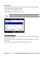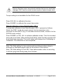
1
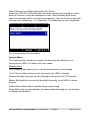
UMC-4
Universal Motor Controller
U S E R
th
M A N U A L
Date: 9 February 2015
Page 2 of 54
Universal Motor Controller UMC-4 – User Manual – V 02/2015
Imprint
Copyright © 2014 Arnold & Richter Cine Technik GmbH & Co. Betriebs KG.
All rights reserved. No portions of this document may be reproduced
without prior written consent of Arnold & Richter Cine Technik GmbH & Co.
Betriebs KG. Specifications are subject to change without notice. Errors,
ommissions, and modifications excepted. ARRI, ALEXA, LDS and LENS
DATA SYSTEM are trademarks or registered trademarks of Arnold &
Richter Cine Technik GmbH & Co. Betriebs KG. All other brands or
products are trademarks or registered trademarks of their respective
holders and should be treated as such. Original version.
For further assistance:
ARRI Cine + Video Geräte Gesellschaft m.b.H.
Pottendorferstraße 25-27/3/1
A-1120 Vienna
Austria
E-mail: [email protected]
www.arri.com
Scope
This instruction manual applies to the following product: Universal Motor
Controller UMC-4 with Software Update Package (SUP) 1.1
Document Information
Version
Document No.
Date
01
K5.0003467
28.08.2014
02
K5.0003467
09.02.2015
Universal Motor Controller UMC-4 – User Manual – V 02/2015
Page 3 of 54
Table of Contents
Disclaimer ................................................................................................... 6 For Your Safety .......................................................................................... 9 Risk Levels and Alert Symbols .......................................................... 9 Vital Precautions .............................................................................. 10 General Precautions ........................................................................ 10 Audience and Intended Use ............................................................. 10 Introduction .............................................................................................. 11 How to Use This Manual .................................................................. 12 Scope of Delivery ............................................................................. 12 System Requirements ...................................................................... 12 QUICK START GUIDE .............................................................................. 12 Mounting on Camera ....................................................................... 13 Powering up ..................................................................................... 13 Setting Time and Date ..................................................................... 13 Setting up Motors ............................................................................. 13 Connecting to Hand Unit .................................................................. 15 Selecting a Lens File ........................................................................ 15 Interfaces .................................................................................................. 17 Optional Connector Modules ........................................................... 20 Control Panel ............................................................................................ 21 Soft Buttons ..................................................................................... 21 Menu Navigation .............................................................................. 22 POWER/LOCK Button ..................................................................... 22 HOME Button ................................................................................... 22 USER Button .................................................................................... 22 MENU Button ................................................................................... 22 Page 4 of 54
Universal Motor Controller UMC-4 – User Manual – V 02/2015
HOME ........................................................................................................ 23 HOME>RADIO ................................................................................. 23 HOME>LENS ................................................................................... 23 HOME>INFO.................................................................................... 23 HOME>FOCUS................................................................................ 24 HOME>IRIS ..................................................................................... 24 HOME>ZOOM ................................................................................. 24 Info Area .......................................................................................... 24 MENU ......................................................................................................... 25 Motors Menu .................................................................................... 26 Radio Menu ...................................................................................... 28 Lens Menu ....................................................................................... 28 Metadata Menu ................................................................................ 30 Focus/Zoom Demands Menu ........................................................... 32 System Menu ................................................................................... 33 USER ......................................................................................................... 38 Web Interface ............................................................................................ 39 VNC Viewer ..................................................................................... 40 Metadata .................................................................................................... 41 Appendix ................................................................................................... 43 Antenna Connector .......................................................................... 43 Cables and Accessories .................................................................. 43 Compatible Products ........................................................................ 44 Connector Pinouts ........................................................................... 45 Dimensions and Weight ................................................................... 49 Electrical Data .................................................................................. 50 Radio System ................................................................................... 50 Troubleshooting ............................................................................... 51 ARRI Service Contacts .................................................................... 51 International Declarations and Certifications ................................... 52 Universal Motor Controller UMC-4 – User Manual – V 02/2015
Page 5 of 54
Disclaimer
Before using the products described in this manual be sure to read and
understand all respective instruction.
The ARRI Universal Motor Controller UMC-4 is only available to
commercial customers. The customer grants by utilization that the UMC-4
or other components of the system are deployed for commercial use.
Otherwise the customer has the obligation to contact ARRI preceding the
utilization.
While ARRI endeavors to enhance the quality, reliability and safety of their
products, customers agree and acknowledge that the possibility of defects
thereof cannot be eliminated entirely. To minimize risk of damage to
property or injury (including death) to persons arising from defects in the
products, customers must incorporate sufficient safety measures in their
work with the system and have to heed the stated canonic use.
ARRI or its subsidiaries do not assume any responsibility for incurred
losses due to improper handling or configuration of the UMC-4 or other
system components.
ARRI assumes no responsibility for any errors that may appear in this
document. The information is subject to change without notice.
For product specification changes since this manual was published, refer to
the latest publications of ARRI data sheets or data books, etc., for the most
up-to-date specifications. Not all products and/or types are available in
every country. Please check with an ARRI sales representative for
availability and additional information.
Neither ARRI nor its subsidiaries assume any liability for infringement of
patents, copyrights or other intellectual property rights of third parties by or
arising from the use of ARRI products or any other liability arising from the
use of such products. No license, express, implied or otherwise, is granted
under any patents, copyrights or other intellectual property right of ARRI or
others.
ARRI or its subsidiaries expressly exclude any liability, warranty, demand
or other obligation for any claim, representation, or cause, or action, or
whatsoever, express or implied, whether in contract or tort, including
negligence, or incorporated in terms and conditions, whether by statue, law
or otherwise.
Page 6 of 54
Universal Motor Controller UMC-4 – User Manual – V 02/2015
In no event shall ARRI or its subsidiaries be liable for or have a remedy for
recovery of any special, direct, indirect, incidental, or consequential
damages, including, but not limited to lost profits, lost savings, lost
revenues or economic loss of any kind or for any claim by third party,
downtime, good-will, damage to or replacement of equipment or property,
any cost or recovering of any material or goods associated with the
assembly or use of our products, or any other damages or injury of the
persons and so on or under any other legal theory.
In the case one or all of the foregoing clauses are not allowed by applicable
law, the fullest extent permissible clauses by applicable law are validated.
cJSON library: Copyright (c) 2009 Dave Gamble.
Permission is hereby granted, free of charge, to any person obtaining a
copy of this software and associated documentation files (the "Software"),
to deal in the Software without restriction, including without limitation the
rights to use, copy, modify, merge, publish, distribute, sublicense, and/or
sell copies of the Software, and to permit persons to whom the Software is
furnished to do so, subject to the following conditions: The above copyright
notice and this permission notice shall be included in all copies or
substantial portions of the Software.
THE SOFTWARE IS PROVIDED "AS IS", WITHOUT WARRANTY OF
ANY KIND, EXPRESS OR IMPLIED, INCLUDING BUT NOT LIMITED TO
THE WARRANTIES OF MERCHANTABILITY, FITNESS FOR A
PARTICULAR PURPOSE AND NONINFRINGEMENT. IN NO EVENT
SHALL THE AUTHORS OR COPYRIGHT HOLDERS BE LIABLE FOR
ANY CLAIM, DAMAGES OR OTHER LIABILITY, WHETHER IN AN
ACTION OF CONTRACT, TORT OR OTHERWISE, ARISING FROM, OUT
OF OR IN CONNECTION WITH THE SOFTWARE OR THE USE OR
OTHER DEALINGS IN THE SOFTWARE.
lwIP TCP/IP stack: Copyright (c) 2001-2004 Swedish Institute of Computer
Science. All rights reserved. Redistribution and use in source and binary
forms, with or without modification, are permitted provided that the
following conditions are met:
Universal Motor Controller UMC-4 – User Manual – V 02/2015
Page 7 of 54
1. Redistributions of source code must retain the above copyright notice,
this list of conditions and the following disclaimer.
2. Redistributions in binary form must reproduce the above copyright
notice, this list of conditions and the following disclaimer in the
documentation and/or other materials provided with the distribution.
3. The name of the author may not be used to endorse or promote
products derived from this software without specific prior written
permission.
THIS SOFTWARE IS PROVIDED BY THE AUTHOR “AS IS” AND ANY
EXPRESS OR IMPLIED WARRANTIES, INCLUDING, BUT NOT LIMITED
TO, THE IMPLIED WARRANTIES OF MERCHANTABILITY AND
FITNESS FOR A PARTICULAR PURPOSE ARE DISCLAIMED. IN NO
EVENT SHALL THE AUTHOR BE LIABLE FOR ANY DIRECT, INDIRECT,
INCIDENTAL, SPECIAL, EXEMPLARY, OR CONSEQUENTIAL
DAMAGES (INCLUDING, BUT NOT LIMITED TO, PROCUREMENT OF
SUBSTITUTE GOODS OR SERVICES; LOSS OF USE, DATA, OR
PROFITS; OR BUSINESS INTERRUPTION) HOWEVER CAUSED AND
ON ANY THEORY OF LIABILITY, WHETHER IN CONTRACT, STRICT
LIABILITY, OR TORT (INCLUDING NEGLIGENCE OR OTHERWISE)
ARISING IN ANY WAY OUT OF THE USE OF THIS SOFTWARE, EVEN
IF ADVISED OF THE POSSIBILITY OF SUCH DAMAGE.
FreeRTOS V7.5.3 - Copyright (C) 2013 Real Time Engineers Ltd. All rights
reserved. http://www.FreeRTOS.org
VNC is a registered trademark of RealVNC Ltd. in the U.S. and in other
countries.
Page 8 of 54
Universal Motor Controller UMC-4 – User Manual – V 02/2015
For Your Safety
Always keep this document on hand. It should be read, understood and
observed by all persons using the Universal Motor Controller UMC-4. All
other products must be handled as prescribed by their manufacturers.
Risk Levels and Alert Symbols
Safety warnings, safety alert symbols, and signal words in these
instructions indicate different risk levels:
This symbol alerts you to personal injury hazards or damage to the
equipment. Obey all warnings that follow this symbol to avoid possible
injury or death or damage to the equipment.
This symbol alerts you to electrical hazards. Obey all warnings that
follow this symbol to avoid possible injury or death.
DANGER!
Indicates an imminent, hazardous situation which, if not avoided, will result
in death or serious injury.
NOTICE: Explains practices not related to physical injury. The safety alert
symbol is not used with this signal word.
Note: Provides additional information to clarify or simplify a procedure.
Universal Motor Controller UMC-4 – User Manual – V 02/2015
Page 9 of 54
Vital Precautions
NOTICE: Read and follow all instructions before using the product. Use the
product only as described therein. Never open it. Never insert objects.
Never attempt to repair the product: Always have it repaired and serviced
by authorized ARRI Service Centers.
Never remove or deactivate any product safety equipment (incl. guarantee
stickers).
Always protect the product from moisture, cold, heat, dirt, vibration, shock,
or aggressive substances.
General Precautions
Use only the tools, materials and procedures recommended in this
document. Unplug all cables during transport.
Do not store the UMC-4 in places where it may be subject to temperature
extremes, direct sunlight, high humidity, severe vibration, or strong
magnetic fields.
Audience and Intended Use
NOTICE: The product is solely and exclusively available for commercial
customers and shall be used by skilled personnel only. Always contact
ARRI preceding other uses. Every user should be trained according to
ARRI guidelines.
The UMC-4 is a motor controller solely and exclusively for iris, focus or
zoom control and lens data capture:
•
Wireless via ARRI white radio modem
• Wired via ARRI LCS connection, serial or Ethernet interfaces
Never use the product for any other purpose. Always follow the valid
instructions and system requirements for all equipment involved.
Page 10 of 54
Universal Motor Controller UMC-4 – User Manual – V 02/2015
Introduction
The Universal Motor Controller UMC-4 is an advanced 3-axis motor
controller. Up to three different hand units can connect to the UMC-4 at the
same time, controlling focus, iris and zoom on any camera. The intuitive
user interface helps to quickly setup the system and makes it easy to use.
The high-performance radio system offers reliable radio connectivity.
The UMC-4 incorporates the LDS Lens Data Archive and generates frameaccurate lens data with any lens. Lens data is used for lens mapping to
pre-marked focus rings and depth-of-field display on the WCU-4 hand unit.
It also enables focus tracking – setting the focus motor to continuously
follow a subject by using an ultrasonic distance measurer. For VFX tasks in
post, the UMC-4 records lens data with timecode and inclinometer data,
helping match the virtual lens to the recorded image.
The UMC-4 supports internal and external timecode that is recorded with
frame-accurate lens data onto SD card, making the lens data usable for
postproduction. The internal timecode clock can be jam-synced from
external devices, but can output LTC timecode as well.
The UMC-4 includes multiple interfaces for maximum flexibility on set. Two
serial interfaces connect peripheral equipment such as ARRI’s UDM-1
distance measure. Optional connector modules interface directly with focus
and zoom demands from Fujifilm and Canon. An Ethernet connector
integrates the UMC-4 with standard IT equipment.
The UMC-4 is splash-proof and embodies the reliability and durability for
which ARRI is famous. The worldwide ARRI Service network ensures rapid
second level support if needed. New firmware versions can be installed to
the unit by means of an SD card.
Visit www.arri.com/ecs/umc-4 for up-to-date product information and
software updates.
Universal Motor Controller UMC-4 – User Manual – V 02/2015
Page 11 of 54
How to Use This Manual
Connectors are written in all capital letters, for example, FOCUS.
Buttons are written in all capital letters, for example, USER button.
Menus and screens are written in italic letters, for example, Lens menu and
Home screen.
The appendix at the back of the manual contains useful reference material
including radio frequencies, spare parts and additional accessories,
connector pin-out diagrams and dimensional drawings.
Scope of Delivery
On delivery, please check if the package and its contents are intact. Never
accept a damaged/incomplete delivery. A complete delivery includes:
•
•
•
•
•
Universal Motor Controller UMC-4, including antenna
L-Bracket
SD card
Instruction manual
Original packaging
For scope of warranty, please ask your local ARRI representative. ARRI is
not liable for consequences from inadequate shipment, improper use, or
third-party products.
System Requirements
To tap the full potential of the device, have all connected units updated to a
firmware equal or higher to those listed below.
Product
Firmware
Wireless Compact Unit WCU-4
SUP 2.0
Page 12 of 54
Universal Motor Controller UMC-4 – User Manual – V 02/2015
Product
Firmware
Single Axis Unit SXU-1
SUP 1.0
Zoom Main Unit ZMU-3A
SUP 02G
Wireless Zoom Extension WZE-3
SUP 02A
QUICK START GUIDE
This quick start guide walks you through setting up the UMC-4 with one
hand unit and three motors for wireless lens control.
Mounting on Camera
Mount the UMC-4 on the camera, preferably in a vertical position by using
the L-Bracket, with the antenna pointing upwards and the motor connectors
pointing towards the lens. Such a position is necessary for the generation
of valid tilt and roll data from the built-in inclinometer.
Powering up
Connect the UMC-4 to a power source with one of the power cables listed
on pages 41 and 42. Power-up the unit by pressing the power button
momentarily.
Setting Time and Date
The time and date of the device are factory preset; however, they are set to
Central European Time, which might not be suitable for your location. To
set time and date, go to Menu>System>Date/Time>Set Date/Time.
Time and date are used in the naming of metadata files recorded to SD
card, as well as in the log file. The UMC-4 will keep time and date even if it
is disconnected from a power source, as it includes a built-in lithium battery
that normally lasts for more than five years.
Setting up Motors
Attach the motors for focus, iris and/or zoom to the lens. Make sure the
motors are properly mounted to their respective lens axes and will not
loosen up when operated.
Universal Motor Controller UMC-4 – User Manual – V 02/2015
Page 13 of 54
Connect the motor cables to their respective FOCUS, IRIS and ZOOM
connectors on the UMC-4.
Go to the Focus, Iris or Zoom sub-page of the Home screen and press
CAL. ALL to calibrate all motors.
Page 14 of 54
Universal Motor Controller UMC-4 – User Manual – V 02/2015
Set up the motor mounting side and torque (if applicable) in the Focus, Iris
and Zoom sub-page of the Home screen.
Side refers to the side of the lens the motor is mounted to (on standard
support rods underneath the lens).
Torque refers to the motor torque; a higher value means higher torque.
Connecting to Hand Unit
Set the radio channel on the UMC-4 in the Radio sub-page of the Home
screen. Make sure that the radio power is switched on and that the
selected radio channel is not already in use by another motor controller.
Set the hand unit to the same radio channel (see the hand unit’s user
manual for further instructions). Once connected, the UMC-4 status LED
will turn blue and the number of connected hand units will display on the
UMC-4 Home screen.
Selecting a Lens File
Select a lens table if you want to display lens data on the WCU-4 hand unit,
or use lens mapping to pre-marked focus rings and focus tracking with the
WCU-4 hand unit, or record lens data to SD card:
Go to the Lens sub-page of the Home screen.
Go to Add to Favorites and select the lens you want to use from the list.
Press ADD+USE to use the lens table and add it to your list of favorites.
You are now ready to shoot.
Universal Motor Controller UMC-4 – User Manual – V 02/2015
Page 15 of 54
Note: After connecting a lens motor to the UMC-4 and the lens, it must be
calibrated. The lens motor must be recalibrated under the following
conditions:
•
When the lens motor is detached from the lens
•
After changing lenses
•
After a change in motor position while powered down
Omitting motor calibration might lead to damage of the lens due
to the high level of motor torque!
Note: You can program a custom lens file through the ALEXA web
interface or with the Wireless Compact Unit WCU-4 (SUP 2.0 onwards)
Page 16 of 54
Universal Motor Controller UMC-4 – User Manual – V 02/2015
Interfaces
The UMC-4 includes multiple interfaces for maximum flexibility on set.
Antenna
SERIAL Interface
Module
Status LED
LCS
Connector
CAM
Connector
FOCUS Motor
Connector
RS IN
Connector
IRIS Motor
Connector
TC
Connector
ZOOM Motor
Connector
Universal Motor Controller UMC-4 – User Manual – V 02/2015
Page 17 of 54
3/8“ UNC-16
Mounting Point
M4 Mounting
Points
ETHERNET
SD Card Slot
Connector
Interface
Description
Antenna
Rugged outdoor antenna
SERIAL Interface
Module
Two serial interface connectors to attach peripheral
equipment like Ultrasonic Distance Measure UDM-1.
Note: Further protocols will be added with
subsequent software updates.
Optional modules:
UMC-4 connector module to Canon focus/zoom
demands CAN-1
UMC-4 connector module to Fujinon focus/zoom
demands FUJ-1
Page 18 of 54
Universal Motor Controller UMC-4 – User Manual – V 02/2015
Interface
Description
Status LED
Indicates controller status:
Blue = radio connection is established, motors are
calibrated, no warnings
Green = wired connection is established, motors are
calibrated, no warnings
Yellow = motors are calibrated, but no controlling
device connected
Yellow flashing = motors are currently calibrating
Red = motors are not calibrated, not ready to use for
lens control
LCS Connector
Connects to hand units via ARRI LCS cable, for
wired operation
CAM Connector
Multi-pin connector, offering a variety of protocols,
providing REC and tally control for most film and
digital cameras
FOCUS Motor
Connector
Connects to ARRI Controlled Lens Motor
RS IN Connector
Connects to power source (9.5-34 V), triggers REC
and receives tally status via camera RS interface
IRIS Motor
Connector
Connects to ARRI Controlled Lens Motor
TC Connector
LTC timecode input and output
ZOOM Motor
Connector
Connects to ARRI Controlled Lens Motor
ETHERNET
Connector
Connects to Ethernet and provides access to the
UMC-4 web interface
SD Card Slot
Mounts an SD card
3/8” UNC Mounting
Point
Mounting point for accessories like L-Bracket or VPlate
M4 Mounting
Points
Mounting point for accessories
Universal Motor Controller UMC-4 – User Manual – V 02/2015
Page 19 of 54
Optional Connector Modules
Two optional connector modules interface directly with broadcast-style
focus and zoom demands from Fujifilm and Canon. They replace the
standard SERIAL connector module that is delivered with the UMC-4.
The installation of the connector modules requires basic skills and
knowledge of electronics. Please follow the installation instructions
delivered with the modules or contact ARRI Service.
K2.0002043
Module to Fujifilm focus/zoom demands FUJ-1
K2.0002042
Module to Canon focus/zoom demands CAN-1
Page 20 of 54
Universal Motor Controller UMC-4 – User Manual – V 02/2015
Control Panel
The UMC-4 features a comfortable and comprehensive user interface with
backlit buttons enabling the user to quickly configure the system. The 2.4”
transflective LCD display shows vital status information and is easily
readable in any ambient light conditions.
Fig. 1: UMC-4 Control Panel
Soft Buttons
Six soft buttons are located above and below the display. They change
their behavior depending on the screen content. Two rows at the top and
the bottom of the screen show the function related to each button. Buttons
without a label have no function in that screen.
Universal Motor Controller UMC-4 – User Manual – V 02/2015
Page 21 of 54
Menu Navigation
To access a new menu level, press the SELECT soft button. To go one
level back up, press the BACK soft button.
Use the up/down arrow soft buttons to navigate through the menu.
A parameter has its value displayed on the right hand of the screen. Edit it
with the CHANGE soft button. Cancel an edit action by pressing the BACK
(or depending on the context, the CANCEL) soft button.
POWER/LOCK Button
Press and release to switch the UMC-4 on; to switch off the UMC-4, the
button must be pressed for three seconds, and a countdown is displayed. If
the button is released before the countdown has elapsed, the UMC-4 does
not shut down.
Press and release the POWER/LOCK button twice to lock or unlock the
user interface. A lock or unlock status symbol will be displayed.
HOME Button
Press the HOME button to enter the Home screen.
USER Button
Press the USER button to enter the User screen, providing user-definable
function shortcuts.
MENU Button
Press the MENU button to enter the UMC-4 main menu. The main menu
includes sub menus for system setup, firmware updates, Lens Data
Archive, and more.
Page 22 of 54
Universal Motor Controller UMC-4 – User Manual – V 02/2015
HOME
The Home screen is the default screen. It shows the most important
parameters and gives quick access to changing them through the six soft
buttons:
HOME>RADIO
The RADIO soft button area displays the currently selected radio channel
and the number of connected hand units. The soft button is a shortcut to
Menu>Radio. The radio can be switched on or off and the radio channel
can be selected.
Radio Status
Radio status levels are:
•
Off: Radio modem is switched off.
•
Initialize…: Radio modem is initializing.
•
Ready: Radio modem is initialized and ready to connect to the
indicated radio channel.
•
Units 1-3: Radio is connected to between one and three hand
units.
•
Blocked: Another motor controller is already using the currently
selected radio channel. Select another radio channel!
HOME>LENS
The LENS soft button area displays the currently selected lens file.
The soft button is a shortcut to Menu>Lens. The Lens menu contains the
Lens Data Archive with pre-programmed lens tables for many common
lenses. Select a lens file to use lens data on the WCU-4 hand unit or if you
want to record lens data for postproduction.
HOME>INFO
The INFO soft button area displays warnings and errors. Press the soft
button to open the live info screen. The live info screen displays the UMC4’s current system state and current error messages, and provides the
following sub-screens:
Universal Motor Controller UMC-4 – User Manual – V 02/2015
Page 23 of 54
•
SYSTEM: Shows the UMC-4 firmware version, the device’s serial
number and the voltage level of the power supply
SD CARD: Shows the SD card capacity and the number of
recorded metadata clips
Press the CLEAR soft button to reset warning and error messages.
•
HOME>FOCUS
The FOCUS soft button area displays the motor type, the side the motor is
currently set on, and the motor status. The soft button is a shortcut to
Menu>Motors>Focus, where you can set the motor side and motor torque.
HOME>IRIS
The IRIS soft button area displays the motor type, the side the motor is
currently set on, and the motor status. The soft button is a shortcut to
Menu>Motors>Iris, where you can set the motor side and motor torque.
HOME>ZOOM
The ZOOM soft button area displays the motor type, the side the motor is
currently set on, and the motor status. The soft button is a shortcut to
Menu>Motors>Zoom, where you can set the motor side and motor torque.
Motor Status
Motor status levels are:
•
None: No motor connected
•
Calibrate!: Motor needs to be calibrated
•
Calibrating: Motor is currently calibrating
•
Idle: Motor is not assigned to hand unit
•
Ready: Motor is ready to use
Info Area
The info area in the center of the Home screen shows camera index
(if set), timecode (if active), the camera recording status and SD card
status.
Page 24 of 54
Universal Motor Controller UMC-4 – User Manual – V 02/2015
SD Card Status
The SD card status is indicated by the color of the SD card symbol on the
center right side of the HOME screen. The symbol will only show up if an
SD card is inserted.
•
White-colored symbol: SD card is inserted, write-protection is
disabled, and ready to record
•
Grey-colored symbol: SD card is inserted, but is write-protected
Red-colored symbol: Data is currently being recorded on the SD
card
The percentage value to the right of the SD card symbol indicates the free
capacity left on the SD card.
•
Note: Do not remove the SD card during recording!
MENU
The Menu contains parameters for the basic UMC-4 setup. It has a tree
structure and the current path in the menu is displayed in the top section of
every screen.
Fig. 2: UMC-4 Menu
Universal Motor Controller UMC-4 – User Manual – V 02/2015
Page 25 of 54
Motors Menu
The Motors menu lets you set up the focus, iris and zoom motor, calibrate
motors and select the calibration speed.
Press CAL ALL to calibrate all motors.
Press INFO to get a motor status overview.
Select Low calibration speed for mechanically delicate lenses.
Fig. 3: Motors Menu
Focus, Iris, Zoom Menu
The Focus, Iris and Zoom menu pages allow the setting of motor mounting
side and motor torque.
Side: Select the side on which the motor or lens data encoder is mounted
to the lens.
Torque: Set the torque level for CLM-3 and CLM-4 motors.
Page 26 of 54
Universal Motor Controller UMC-4 – User Manual – V 02/2015
Ensure that the motor torque level matches the lens to avoid lens
damage. Stiff, hard-to-move lenses require a higher torque level.
Torque setting is not available for the CLM-2 motor.
Press CAL ALL to calibrate all motors.
Press CALIBR. to calibrate the current lens motor.
Manual Calibration of Lens Data Encoder LDE-1
To manually calibrate a Lens Data Encoder LDE-1, proceed as follows:
Attach the LDE-1 to the lens and connect it to its respective motor
connector on the UMC-4 (e.g. if it encodes the focus scale, connect it to the
FOCUS motor socket).
Press CALIBR. or CAL. ALL to activate calibration mode. Turn the encoded
lens scale to its limits. After reaching both limits, leave the lens encoder still
for at least three seconds. The motor status will change from Calibrating to
Calibrated. The calibration is now completed.
Note: The Side setting for lens motors and lens data encoders refers to
mounting on standard support rods on the bottom of the camera.
Note: The Side setting for the LDE-1 lens data encoder refers to mounting
it with the tying knob facing away from the lens.
Universal Motor Controller UMC-4 – User Manual – V 02/2015
Page 27 of 54
Fig. 4: Focus Motor Menu
Radio Menu
The Radio menu lets you switch the radio on and off and select the radio
channel. Select the same channel both on the hand unit and the UMC-4.
Fig. 5: Radio Menu
Lens Menu
The Lens menu contains the Lens Data Archive with a set of pre-defined
lens tables, including ARRI/ZEISS Master Primes, Ultra Primes, Master
Anamorphics, Super Speeds, ARRI/FUJINON Alura Zooms and the ARRI
Ultra Wide Zoom. Commonly used lenses (e.g. during a specific job) can
be added to a user-generated Favorites list for quick access.
Press SHOW to display live lens data.
Page 28 of 54
Universal Motor Controller UMC-4 – User Manual – V 02/2015
Favorites
To add a lens table to the Favorites list, select Add to Favorites from the
Lens menu. This opens the Lens Data Archive including a library of predefined lens tables.
Select a lens type, then a lens model and, in case of Zeiss lenses, a lens
class. The lens class can be found on the lens barrel below the infinity
symbol of the focus scale.
To add the lens table to the Favorites list press ADD; to use it without
adding it to Favorites press USE; or to do both press ADD+USE.
Press REMOVE to delete the currently selected lens table from the
Favorites list. Press REM. ALL to delete all lens tables from the Favorites
list.
Copying Lens Tables from SD Card
Custom lens tables can be added to the Lens Data Archive’s Custom folder
via SD card. To add a new lens table to the UMC-4, place the lens table on
the SD card and insert the SD card into the UMC-4.
Go to Menu>Lens>Copy from SD Card. Navigate the SD card’s file system
until you reach the desired lens table, then press SELECT to select the
specific one lens table or press SEL. ALL to select all lens tables in the SD
card folder. A popup message will appear offering to instantly add the
selected lens table(s) to the favorites list as well. Press YES to add the
table(s) to the Favorites list, press NO to not add the table(s) to the
Favorites list or press CANCEL to cancel the whole operation.
Custom lens tables can be deleted in the Delete Custom Lens Tables
menu.
Note: You can program a custom lens file through the ALEXA web
interface or with the Wireless Compact Unit WCU-4 (SUP 2.0 onwards)
Universal Motor Controller UMC-4 – User Manual – V 02/2015
Page 29 of 54
Copying Lens Tables to SD Card
Lens tables located in the UMC-4 Custom folder of the Lens Data Archive
can be copied to the SD card.
Go to Menu>Lens>Copy from SD Card to copy all lens tables from the
Custom folder to the SD card’s /ARRI/ALEXA/LDA directory.
Fig. 6: Lens Menu
Metadata Menu
The Metadata menu handles the metadata that is recorded onto SD card.
Record Mode
Set Record Mode to Auto if you want metadata to be recorded to SD card
each time the UMC-4 gets a tally (recording) feedback from the camera it is
connected to.
Set to Manual if you want to start metadata recording to SD card manually.
Manual metadata recording can be activated by a USER button. Press the
USER button to enter the User screen and assign Record Metadata to one
of the USER buttons (see the USER menu section). Start manual recording
by pressing the assigned USER button.
We recommend using high quality SD cards with the
UMC-4. We also recommend formatting each card before use,
as this will avoid issues with excessive fragmentation on the
card’s file system.
Page 30 of 54
Universal Motor Controller UMC-4 – User Manual – V 02/2015
Timecode
The UMC-4 can sync to an external LTC timecode. The precise crystal
oscillator in the UMC-4 will count accurately with +/- 1 ppm stability. It is
recommended to jam-sync after every shooting break to avoid the risk of
losing timecode sync during a shot.
The Timecode menu allows the setup and display of timecode. Timecode is
recorded with the metadata onto SD card and can be used to synchronize
metadata with the images in postproduction.
Select Show in Home Screen to switch the timecode display in the info
area of the Home screen on and off.
Select Frame Rate to change the time base (23.97, 24, 25, 29.97,
29.97DF, 30, 30DF).
Select Jam to change the jam sync mode:
•
Off: Jam sync is not active. The UMC-4 continuously generates
timecode itself and functions as a timecode master clock.
•
Once: The UMC-4 synchronizes its timecode with the external LTC
source and continues counting on its own. After synchronization, a
pop-up will appear to indicate the operation was performed.
Cont.: The UMC-4 continuously reads the LTC-timecode signal at
the TC connector as long as it is present. Upon disconnection or
loss of signal, the UMC-4 continues counting on its own. When the
external signal is reconnected, the UMC-4 uses the values of the
external signal again.
Select Set Timecode to set the timecode. Use the arrow soft buttons to
navigate the timecode values. Press the OK soft button to set the
timecode. Press the CANCEL soft button to cancel the timecode setting.
•
Press the SHOW soft button to display the current timecode. Press any soft
button to return to the menu.
Note: It is recommended to jam-sync after every shooting break to avoid
the risk of losing timecode sync during a shot.
Note: The UMC-4 will keep its timecode for at least 30 minutes, even after
disconnection from the power source or if it is switched off.
Universal Motor Controller UMC-4 – User Manual – V 02/2015
Page 31 of 54
Camera ID
The Camera ID entry allows the selection of a camera ID. Use the selection
list to assign a letter from A to Z as per the setting of your camera. This
information will be shown on the Home screen and will be recorded in the
metadata file. By selecting “—“ the camera ID information will be disabled,
both from the Home screen and the metadata file.
Level
Shows the tilt and roll of the UMC-4 in degrees, as measured by the
internal inclinometer. This sensor can be reset if it appears to have an
offset. Press the RESET soft button to reset the sensor.
Note: Mount the UMC-4 on the camera in a defined position. If possible,
use the L-Bracket.
Note: The inclinometer can only be reset while both axes are within a
threshold of +/- 10 degrees around 0.
Fig. 7: Metadata Menu
Focus/Zoom Demands Menu
The Focus/Zoom Demands menu allows the calibration of the broadcaststyle focus and zoom demands.
To calibrate the limits for a demand, connect the demand to the UMC-4
and set the zoom speed control knob to the highest speed setting (‘Fast’ or
‘Max’).
Page 32 of 54
Universal Motor Controller UMC-4 – User Manual – V 02/2015
Select Menu>Focus/Zoom Demands>Set Limits.
Press the FOCUS or ZOOM button and start turning the demand’s control
knob to its limits to activate calibration mode. After reaching both limits,
leave the demand still for at least three seconds. The text on the screen will
change from Calibrating… to Calibrated. The calibration is now completed.
Fig. 8: Focus/Zoom Demands Menu
System Menu
The System menu contains a series of submenus that allows you to
configure the UMC-4 to better suit your needs.
Display Menu
The Display menu allows you to set the preferences for the display:
Color Theme offers various color themes for the UMC-4 display.
Display Backlight lets you set the backlight intensity for the LCD screen.
Button Backlight lets you set the backlight intensity for all UMC-4 control
buttons.
Select Enter Sleep After to set the sleep mode timing.
Sleep Mode lets you set whether the sleep mode will apply to only buttons
or display and buttons.
Universal Motor Controller UMC-4 – User Manual – V 02/2015
Page 33 of 54
Date/Time Menu
By selecting the Date/Time menu you can either show the current date and
time on the screen, or set the current date and time of the UMC-4:
Press the SHOW soft button to display the current time.
Press any soft button to return to the menu.
Enter the Set Time/Date submenu to set the current time and date. Use the
arrow soft buttons to navigate through the time and date settings. Press the
OK soft button to save your settings. Press the CANCEL soft button to
abort the setting and return back to the menu.
Network Menu
The network menu includes the following entries:
Show Parameters: All the relevant parameters of the network interface are
shown in this screen.
Configuration Source: Pressing this button toggles between DHCP and
Manual. If DHCP mode is selected, the UMC-4 will search for a DHCP
server on the LAN to provide all the required network parameters. If
Manual mode is selected, then the next menu Set Parameters will become
active and should be used to manually configure the network parameters.
Set Parameters: This menu is accessible only if the menu entry
Configuration Source is set on Manual. You can set here the IP Address,
the Network Mask, the Gateway Address and the DNS address. Use the
right and left arrows to select a specific parameter and the up and down
arrows to modify their values.
Note: The UMC-4 supports Apple’s Bonjour® protocol; its Bonjour name is
similar to “UMC4-####.local”, where “####” stands for the UMC-4 serial
number. For simple setups consisting of a PC and one or more UMC-4
units, connect the PC to the UMC-4 using a standard Ethernet cable. Make
sure that your PC supports Bonjour protocol (e.g. by installing Apple’s
Safari browser) and select in the Bonjour bookmarks, or type the Bonjour
name of the unit you want to access in the browser’s URL edit box. Set the
Configuration Source in UMC-4 to DHCP.
Page 34 of 54
Universal Motor Controller UMC-4 – User Manual – V 02/2015
Settings Menu
The Settings menu allows users to save the current settings of the UMC-4,
to load some previously saved settings or to load the factory default
settings.
Select the Save Settings menu to save the current settings onto the SD
card (a writable SD card must be inserted in the card slot). The settings file
will be saved in the directory /ARRI/UMC4/settings. If the directory does not
exist, it will be automatically created.
Select Load Settings and navigate to the previously saved settings on the
SD card (normally /ARRI/UMC4/settings). Select the settings file. The
settings in the file will replace the current settings in the UMC-4.
Select Factory Defaults to load the factory defaults into the UMC-4.
Note: The current settings in the UMC-4 will be lost after loading a settings
file!
Note: The current settings in the UMC-4 will be lost after loading the factory
defaults!
Firmware Update Menu
To keep your UMC-4 up-to-date, you may need to update its firmware.
Please check ARRI’s website for the latest firmware packages. To update
the device, proceed as follows:
1. Copy the firmware update package onto an SD card.
2. Insert the SD card in the SD card slot of the UMC-4.
3. Select Menu>System>Firmware Update, and navigate to the
update package on the SD card.
4. Select the package. A list of modules will be shown on the screen.
5. Press UPDATE. A new warning screen will be displayed. Proceed
by simultaneously pressing the two UPDATE buttons. The screen
will blackout and the status LED starts blinking red and green. The
unit is being updated. This can take up to 30 seconds.
Universal Motor Controller UMC-4 – User Manual – V 02/2015
Page 35 of 54
6. The UMC-4 will reboot after the update is completed. Depending
on the update package content, additional modules might need to
be updated after reboot; this is done automatically and is clearly
indicated on the screen of the device. The second phase of the
update procedure may take several minutes.
Do not switch power off and do not remove the SD card during
the update as this may damage the UMC-4! In case of problems,
see the troubleshooting section.
Save Log to SD Card Menu
Select the Save Log to SD Card menu if you want to save the log file to the
SD card. This may be required when you contact the ARRI support staff.
The log file will be saved immediately and can be found in the
/ARRI/UMC4/logs directory.
Format SD Card
Select Format SD Card to format the SD card and add the ARRI specific
directory structure:
/ARRI/UMC4 /Firmware
/Logs
/Metadata
/Settings
Note: All the data on the SD card will be lost after formatting the card!
System Info Menu
Select the System Info menu to identify the current firmware version, the
serial number, and the power source’s current voltage.
Page 36 of 54
Universal Motor Controller UMC-4 – User Manual – V 02/2015
Fig. 9: System Menu
Universal Motor Controller UMC-4 – User Manual – V 02/2015
Page 37 of 54
USER
Pressing the USER button opens the User screen, providing quick links to
important functions/settings. Pressing the USER button a second time will
switch to a configuration screen, where each button can be assigned to
one of the pre-defined functions.
On delivery the UMC-4 comes with factory-programmed functions on each
user button. To change them, enter the configuration screen by pressing
the USER button twice. Select the button from the list, and assign the
desired function. Proceed in a similar way for all user buttons you wish to
reconfigure.
USER assignable functions include:
• None
• Jam Timecode
• Select Lens
• Focus Tracking
• Show Lens Data
• Show Network
• Calibrate Motors
• Radio On/Off
• Set Display
• Record Metadata
• Show Timecode
• Level Sensor
Fig. 10: User Screen
Page 38 of 54
Universal Motor Controller UMC-4 – User Manual – V 02/2015
Web Interface
The UMC-4 includes an embedded web server that can be accessed
through a web browser using Apple’s Bonjour® protocol.
To access the UMC-4 web interface, connect the UMC-4 to a computer
with a standard Ethernet cable. Open the web browser on the computer.
Enter address umc4-####.local, with #### being the UMC-4 serial number.
The web interface displays the current lens data, as well as the current
motor, radio and timecode status. Further functions will become available
with subsequent software updates.
Fig. 11: UMC-4 Web Interface
Universal Motor Controller UMC-4 – User Manual – V 02/2015
Page 39 of 54
VNC Viewer
The UMC-4 includes a VNC® server that can be accessed through a VNC
Viewer. The UMC-4 screen can be remotely displayed and settings can be
remotely changed through the VNC Viewer.
There are many VNC clients for virtually all operating systems that can be
used with the UMC-4. As an example, the VNC Viewer can be downloaded
from https://www.realvnc.com/download/viewer/. Please follow the
installation instructions from the RealVNC website.
To access the UMC-4 VNC server, connect the UMC-4 to a computer with
a standard Ethernet cable. Open the VNC Viewer on the computer. Enter
address umc4-####.local, with #### being the UMC-4 serial number. Set
Encryption to “Let VNC Server choose”. Press the CONNECT button in the
VNC Viewer to connect with the UMC-4. The VNC Viewer will display the
UMC-4 screen.
Press M to enter the Menu.
Press U to enter the User screen.
Press H to return to the Home screen.
Use the cursor of the VNC viewer to push the virtual soft buttons or use the
up/down, left/right and ENTER keys on your computer keyboard.
Fig. 12: VNC Viewer
Page 40 of 54
Universal Motor Controller UMC-4 – User Manual – V 02/2015
Metadata
The UMC-4 records a metadata file when the camera is recording a clip as
long as the UMC-4 receives a tally signal from the camera.
Make sure to insert a write-enabled SD card with enough free
capacity into the UMC-4. Set the UMC-4 to automatic recording
mode (Menu>Metadata>Recording Mode>Auto) to trigger
metadata recording from the camera.
The metadata is recorded in a character-separated values (CSV) file to SD
card. The CSV values are separated by tab stops. The file name contains
the UMC-4 serial number and the date and time of clip generation (e.g.
UMC4-06001_201420140822T192628.csv).
The following metadata is being recorded:
Name
Description
Example
Index
Sequential number
1
Master TC
Timecode
10:08:56:23
Camera Index
Camera index
A
Lens
Lens being used
AZ45250_6045
Lens Distance Unit
Lens scale
Feet
Lens Focus Distance
Focus distance (in 1/1000 m/ft)
14.358
Lens Focal Length
Focal length (in 1/1000 mm)
50.000
Lens Iris
T-stop
T2.8+7/10
Lens Linear Iris
Linear iris value
3725
RawEncoderFocus
RawMotor
Encoder value of focus motor
11251
RawEncoderFocal
RawMotor
Encoder value of zoom motor
9436
Universal Motor Controller UMC-4 – User Manual – V 02/2015
Page 41 of 54
Name
Description
Example
RawEncoderIris
RawMotor
Encoder value of iris motor
4027
EncoderLimFocusMo
torMin
Minimum encoder limit of focus
motor
0
EncoderLimFocusMo
torMax
Maximum encoder limit of focus
motor
21122
EncoderLimFocalMot
orMin
Minimum encoder limit of zoom
motor
0
EncoderLimFocalMot
orMax
Maximum encoder limit of zoom
motor
21122
EncoderLimIrisMotor
Min
Minimum encoder limit of iris
motor
0
EncoderLimIrisMotor
Max
Maximum encoder limit of iris
motor
4585
UMC-4 Tilt
Tilt angle of UMC-4 (degree)
0.1
UMC-4 Roll
Roll angle of UMC-4 (degree)
0.1
Page 42 of 54
Universal Motor Controller UMC-4 – User Manual – V 02/2015
Appendix
Antenna Connector
The radio connection is established via the antenna connected to
the antenna connector. Do not leave the connector open during
operation or transport. The radio module inside could be
damaged by electrostatic discharge via the open connector. We
recommend using the originally supplied antenna only.
Cables and Accessories
The following accessories are compatible with the UMC-4:
K2.0001967
L-Bracket (supplied with UMC-4)
K2.0001758
V-Plate
K2.0002007
Outdoor Antenna (straight) for UMC-4 Motor Controller
(supplied with UMC-4)
K2.0001637
Cable UMC-4 RS IN to RS
K2.0002668
Cable UMC-4 RS IN to D-Tap
K2.0002672
Cable UMC-4 RS IN to PSC (additional PSC cable
required)
K2.0002674
Cable UMC-4 RS IN to open end
K2.0005951
Cable UMC-4 to ALEXA
K2.0001604
Cable UMC-4 to AMIRA (REC start/stop and tally with
AMIRA SUP 1.1 onwards)
K2.0002919
Cable UMC-4 to LANC (additional RS IN cable required)
K2.65205.0
Cable UMC-3/4 to Sony F35/PSC (additional PSC cable
required)
K2.0000321
Cable UMC-3/4 to Sony F55/PSC (additional PSC cable
required)
K2.0002620
Cable UMC-4 to F55 (additional RS IN cable required)
K2.0002656
Cable UMC-4 to F65 (additional RS IN cable required)
K2.65186.0
Cable UMC-3/4 to RED ONE/PSC (additional PSC cable
required)
Universal Motor Controller UMC-4 – User Manual – V 02/2015
Page 43 of 54
K2.0002855
Cable UMC-4 to EPIC (additional RS IN cable required)
K2.65235.0
Cable UMC-3/4 to Video-RS/PSC (additional PSC cable
required)
K2.65012.0
Cable UMC-3/4 to Cooke/i (supported with UMC-4 SUP
1.1)
K2.65063.0
Cable UMC-3/4 to Cine Tape Measure (coiled)
K2.0003252
Cable TC IN/OUT (Ambient)
K2.0003254
Cable TC OUT BNC (Ambient)
K2.0003253
Cable TC IN BNC (Ambient)
K2.0003255
Cable TC OUT for EPIC (Ambient)
K2.0002043
UMC-4 connector module to Fujifilm focus/zoom demands
FUJ-1
K2.0002042
UMC-4 connector module to Canon focus/zoom demands
CAN-1
K2.0002046
UMC-4 connector module with two serial connectors
(supplied with UMC-4)
Compatible Products
The UMC-4 supports the following products:
•
Wireless Compact Unit WCU-4
•
Single Axis Unit SXU-1
•
Zoom Main Unit ZMU-3A
•
Wireless Zoom Extension WZE-3
•
Wireless Compact Unit WCU-3
•
Wireless Main Unit WMU-3
•
Wireless Focus Unit WFU-3
Page 44 of 54
Universal Motor Controller UMC-4 – User Manual – V 02/2015
umc4_manual.pdf
1
27-02-15
16:26
•
Wireless Zoom Unit WZU-3
•
Controlled Lens Motor CLM-2
•
Controlled Lens Motor CLM-3
•
Controlled Lens Motor CLM-4
•
Lens Data Encoder LDE-1
•
Ultrasonic Distance Measure UDM-1
Note: Use only one lens motor per lens axis.
Note: Up to three hand units can be connected to one UMC-4 in parallel to
form a radio network.
C
Connector Pinouts
M
Serial
Y
CM
MY
CY
CMY
K
1
2
3
4
5
6
GND
+12V
TxD/Tx–
RxD/Rx+
Tx+
Rx–
Ground
12V output, max 200mA
RS232/RS485 – RS422
RS232/RS485 – RS422
RS422 line
RS422 line
Universal Motor Controller UMC-4 – User Manual – V 02/2015
Page 45 of 54
LCS
1
2
3
4
5
GND
n.c.
CAN-L
CAN-H
+V-BAT
Ground
1
2
3
4
5
GND
+V-BAT
CAM-TYPE
RxRUN-SW1
6
7
8
9
Tx+
CAN-L
n.c.
TALLY
Ground
9.5 V to 34 V DC IN
Camera type sense, analog input
RS422 line
Opto switch1 connects to pin 13 @REC (max.
100 mA/50 V)
RS422 line
CAN bus
CAN bus
CAN bus
Battery supply output
CAM
Page 46 of 54
Tally, analog input, active high (default value:
1.25 V transition level)
Universal Motor Controller UMC-4 – User Manual – V 02/2015
10
Tally, digital input, active low,
11
D-CAM
TALLY
DAC-CAM
12
13
R/S
RUN-SW2
ARRI R/S
Opto switch 2 connects to pin 5 @REC (max.
100 mA/50 V)
14
RxD/Rx+
RS232/RS485 – RS422 together with pins 4, 6,
15
15
16
TxD/TxCAN-H
RS232/RS485 – RS422 with pins 4, 6, 14
CAN bus
REC analog output, active high (default value
@REC: 3.3 V)
FOCUS/IRIS/ZOOM
1
2
3
4
5
6
7
8
9
10
11
12
GND
MTYPE-A
MTYPE-B
MTYPE-C
+5V
Encoder-A
Encoder-B
n.c.
n.c.
n.c.
Motor +
Motor –
Ground
Motor type sense
Motor type sense
Motor type sense
Encoder supply
Encoder input A
Encoder input B
Motor drive output
Motor drive output
Universal Motor Controller UMC-4 – User Manual – V 02/2015
Page 47 of 54
RS IN
1
2
3
GND
+V-BAT
R/S
Ground
9.5 V to 34 V DC IN
ARRI R/S
GND
LTC-IN
n.c.
n.c.
LTC-OUT
Ground
Timecode input
TC
1
2
3
4
5
Page 48 of 54
Timecode output
Universal Motor Controller UMC-4 – User Manual – V 02/2015
Dimensions and Weight
Weight (including antenna): 428 g
Universal Motor Controller UMC-4 – User Manual – V 02/2015
Page 49 of 54
Electrical Data
Supply Voltage:
9.5 V to 34 V DC (full motor speed)
Current Consumption:
135 mA@12 V (radio on/ready)
70 mA@24 V (radio on/ready)
Operating Temperature:
-20 to +50 °C (-4 to +122 °F)
Radio System
The UMC-4 contains a radio unit that enables wireless lens control and
lens data communication with a white coded radio module. A white ring at
the base of the antenna mount point identifies it. It offers 8 channels to
choose from:
Channel
Frequency
0
2.410 GHZ
1
2.415 GHZ
2
2.430 GHZ
3
2.435 GHZ
4
2.450 GHZ
5
2.455 GHZ
6
2.470 GHZ
7
2.475 GHZ
White radio and legacy yellow radio cannot be mixed in the same radio
network of camera and hand units. It is possible to use both systems in
parallel within different radio networks.
Page 50 of 54
Universal Motor Controller UMC-4 – User Manual – V 02/2015
Troubleshooting
Problem
Symptom
Remedy
Software update
failed
During the update, the
status LED ceases to
blink (is solid green), or
it blinks with a constant
duty cycle and the unit
does not re-start by
itself.
Restart the UMC-4 manually
by pressing the POWER
button for 6 seconds or
more, until the LED goes off;
wait 3 seconds and restart
the unit. If it still doesn’t
start, contact ARRI Service.
UMC-4 does not
power up
The UMC-4 does not
boot up after pressing
the POWER button.
The internal lithium battery
might be empty. Press the
power button for 3-5
seconds to power up the
UMC-4. Have the internal
battery replaced by ARRI
Service.
ARRI Service Contacts
Munich, Germany
Arnold & Richter Cine Technik
+49 89 3809 2121
[email protected]
Business hours:
Mo. - Fr. 9:00 - 17:00 (CET)
London, Great Britain
ARRI CT Limited
+44 1895 457 051
[email protected]
Business hours:
Mo. - Thu. 9:00 - 17:30 (GMT)
Fr. 9:00 - 17:00 (GMT)
Milan, Italy
ARRI Italia S.r.l.
+39 (02)262 271 75
[email protected]
Business hours:
Mo. - Fr. 9:00 - 18:00 (CET)
Burbank, USA
ARRI Inc. West Coast
+1 877 565 2774
[email protected]
Business hours:
Mo. - Fr. 8:15 - 17:00 (PST)
Universal Motor Controller UMC-4 – User Manual – V 02/2015
Page 51 of 54
New York, USA
ARRI Inc. East Coast
+1 877 565 2774
[email protected]
Business hours:
Mo. - Fr. 8:00 - 17:30 (EST)
Mississauga, Canada
ARRI Canada Limited
+1 416 255 3335
[email protected]
Business hours:
Mo. - Fr. 8:30 - 17:00 (EDT)
Hong Kong, China
ARRI Asia Limited
+852 2537 4266
[email protected]
Business hours:
Mo. - Fr. 10:00 - 18:30 (HKT)
Beijing, China
ARRI China Co. Limited
+86 10 5900 9680
[email protected]
Business hours:
Mo. - Fr. 9:00 - 18:00 (CST)
Sydney, Australia
ARRI Australia Pty Ltd
+61 2 9855 4305
[email protected]
Business hours:
Mo. - Fr. 8:00 - 18:00 (AEST)
International Declarations and Certifications
EC Declaration of Conformity
The product Universal Motor Controller UMC-4 conforms with the
specifications of the following European directives:
•
Directive 2014/30/EU of the European Parliament and the Council
of 26 February 2014 on the harmonization of the laws of the
Member States relating to electromagnetic compatibility
•
Directive 1999/5/EC of the European Parliament and the Council of
9 March 1999 on radio equipment and telecommunications
terminal equipment and the mutual recognition of their conformity
•
Directive 2011/65/EU of the European Parliament and the Council
of 8 June 2011 on the restriction of the use of certain hazardous
substances in electrical and electronic equipment
Page 52 of 54
Universal Motor Controller UMC-4 – User Manual – V 02/2015
The compliance with the requirements of the European Directives was
proved by the application of the following harmonized standards:
•
EN 55022; EN 55103-1; EN 55103-2; EN 301 489-1; EN 301 48917; EN 62479; EN 60950-1; DIN EN 50581
FCC Class A Statement:
Note: This equipment has been tested and found to comply with the limits
for a Class A digital device, pursuant to Part 15 of the FCC Rules. These
limits are designed to provide reasonable protection against harmful
interference when the equipment is operated in a commercial environment.
This equipment generates, uses, and can radiate radio frequency energy
and, if not installed and used in accordance with the instruction manual,
may cause harmful interference to radio communications. Operation of this
equipment in a residential area is likely to cause harmful interference in
which case the user will be required to correct the interference at his own
expense.
Contains Transceiver module FCC-ID: Y7N-EMIP100
Industry Canada Compliance Statement
Complies with the Canadian ICES-003 Class A specifications.
Cet appareil numérique de la Classe A est conforme à la norme NMB-003
du Canada.
This device complies with RSS 210 of Industry Canada. This Class A
device meets all the requirements of the Canadian interference-causing
equipment regulations.
Cet appareil numérique de la Classe A respecte toutes les exigences du
Réglement sur le matériel brouilleur du Canada.
Contains Transceiver Module IC-ID: 9482A-EMIP100
Please check local regulations for disposal of batteries. The
battery should never be placed in municipal waste. Use a battery
disposal facility if available.
Universal Motor Controller UMC-4 – User Manual – V 02/2015
Page 53 of 54
Page 54 of 54
Universal Motor Controller UMC-4 – User Manual – V 02/2015
Ident.-No.: K5.0003467 · Technical data subject to change without further notice. © ARRI/2015
Arnold & Richter Cine Technik GmbH & Co. Betriebs KG · Türkenstr. 89 · D-80799 Munich · Phone +49 (0)89 3809 0