1
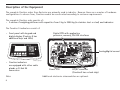
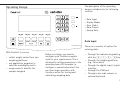
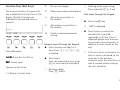
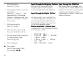
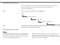
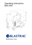
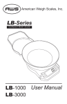
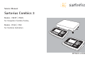
Service Manual
Sartorius Combics 3
Models CW3P | CW3S
for Complete Combics Scales,
Models CISL3 | CIS3
for Combics Indicators
WCI5003-e03082
2
Contents
04
04
04
05
05
06
07
07
08
09
09
10
10
10
11
11
12
12
13
13
14
16
16
16
16
Overview
Service Concept
General Information
Different to Combics1/2
Accompanying Literature
Description of the Equipment
Operating Design
Data Input
Keypad Input
Function Keys (Soft Keys)
Numeric Input Through the Keypad
Input Through the Weighing Platform
Input Through the Digital I/O Port
Input Through the COM Port
Activating the xBPI Protocol
Activating the Service Mode
Activating the Service Mode
Turn on the Combics
Open the menu
Exiting the Service mode
Service Menu
Configuring the Analog/Digital Converter
Purpose
Features
Note on Settings
17 Overview of the Setup Menu in Service Mode
17
Input of the service password
17
Setup - Device - WP1
18
WP1 - Internal - Calibration / Adjustment
19
Setup - Device - WP1 / COM1 / COM2
20
Setup-Menu for A/D Converter Configuration
(Page1)
21
Setup-Menu for A/D Converter Configuration
(Page2)
22 Type Designation
22
Complete Combics scale
22
Complete Combics stainless steel scale
3
Overview
General
Service Concept
Prerequisites for performing maintenance and repair work on Sartorius Combics
scales requires considerable experience with both indicators and weighing
platforms.
In case of defects, repairs are performed on site. Generally, the equipment is not
replaced.
General Information
– Do not connect or disconnect cables to or from the equipment; always
disconnect the power cable from the wall socket (mains supply) first!
– To ensure safety, an isolating transformer must be installed between the
indicator and the power supply before performing work that entails opening
the Combics indicator housing.
4
Different to Combics1/2
–
–
–
–
–
–
–
Important:
Indicator
Operating Concept
Activating the XBPI Protocol
Activating the Service Mode
Service Mode
A/D Converter Configuration
Additional Menus in Service Mode
Mechanical and electrical service or repair work on the complete Combics scale
requires considerable experience, and for this reason should be performed only
by Sartorius technicians trained at the factory. Any attempt to perform repair
work can result in damage to the equipment.
Accompanying Literature
Operating instructions for
“Complete Combics 3 Scales“
Operating instructions for
“Combics 3 Indicators“
Operating instructions for
“Basic Application Programs“
Service Manual
“Combics 1 | Combics 2“
WCW6002-e02101
98648-011-25
WCI6002-e02101
98648-011-20
WCI6003-e02101
98646-002-06
WCI5001-e02104
5
Description of the Equipment
The complete Combics scales from Sartorius are primarily used in industry. Because there are a number of hardware
configurations to choose from, Combics models are constructed according to customer requirements.
The complete Combics scale consists of:
– A choice of weighing platforms with capacities from 3 kg to 3000 kg (in stainless steel or steel) and indicators
The Combics 3-indicators consist of:
– Front panel with keypad and
digital display (Combics 2 has
additional keys and LEDs)
Digital PCB with application
processor, memory, RS-232 interfaces
combics_15_Kl.eps
Analog/digital converter
combics3_04.eps
– Combics indicators
are equipped with either cable
glands or D-Sub 25
connectors.
Note:
6
Power PCB
DC/DC converter
(Combics3 has a clock chip)
Additional electronic subassemblies are optional.
The description of the operating
design is divided into the following
sections:
Operating Design
– Data Input
– Display Modes
– Error Codes
– Data Output
– Saving Data
Data Input
65571-010-03.eps
With Combics 3 you can
– collect weight values from two
weighing platforms
– use application programs to
calculate and display results
– assign codes to identify the
samples weighed
Before you begin, you need to
configure your Combics complete
scale for your requirements. This is
achieved by setting parameters in the
operating menu (for example, to
configure a connected printer). You
can then begin operation, with
functions active for storing and
calculating weighing data.
There are a number of options for
entering data:
– Through the indicator keypad (e.g.,
with the 0, 1, 2... 9keys)
– Through the weighing platform
(e.g., tare values)
– Through the digital input |output
interface
– Through the COM port
– Through a bar code scanner or
external keyboard
7
Keypad Input
Labeled Keys
These keys always have the function
indicated by the label, but the
functions
might not be available at all times.
Whether a function is available at a
given time depends on the operating
state of the scale and the menu
settings active at that time. Some of
the keys have a second function,
activated by pressing and holding the
key for longer than 2 seconds.
e On/off
Turn the Combics on and off or
switch it to the standby mode.
In standby mode, the display shows
OFF.
n Toggle the display between
connected weighing platforms.
With two weighing platforms
connected, this key toggles the
display between the two readouts.
8
( – Zero the scale
– Cancel a calibration/
adjustment procedure
) – Press briefly (< 2 sec):
Tare the weighing platform
– Press and hold (> 2 sec ):
Activate calibration/adjustment
k Toggles the display between:
– first and second weight unit, or
– gross and net values, or
– normal and 10-fold higher
resolution, depending on your
settings in the operating menu.
p – Press briefly: Print
– Press and hold: Print GMP
footer
D Press and hold: Toggle to info
mode (only when an initialized
application is active)
M– Access to Setup program
– Exit the Setup program
c – Press briefly: Quit application
program, delete input character
– Press and hold: Delete entire
input string
0, 1, 2... 9, .
Enter numbers, letters and
other characters
a Toggle between numeric and
alphabetic input
Function Keys (Soft Keys)
o:
Go one level higher
The current function of a given soft
key is indicated in the last line on the
display (footer). Functions are
indicated by abbreviated texts or
symbols .
O:
Show items under selectedentry
Q:
Move up one position in
I/O window
Text Input Through the Keypad
q:
Move down one position in
I/O window
l:
Confirm selected parameter
setting
Softkeys.eps
Numeric Input Through the Keypad
Texts (Examples)
1st ID
ID: Store the first ID line
ESC
ESC: Cancel input
Symbols in the footer:
oo
Return to initial state
$ Deleting entire input string:
Press and hold c (> 2 sec)
§ Enter numbers one digit at a
time: Press 0, 1, 2... 9
as needed
§ Store input:
Press the required key (e.g., press
) to store manual tare input)
§ Press the a key
O
‘ABC’ is displayed
§ Press the key on which the
desired letter is printed
repeatedly, until that letter is
displayed (please note that keys
can activate other characters in
addition to those shown on the
key)
$ If the next letter or character you
wish to enter is activated by the
same key as the previous
character, press the l soft key or
wait 2 seconds before entering
the next character.
$ Deleting a digit:
Press c briefly
9
$ Entering a space:
Press the 0 key
$ Entering punctuation or special
characters:
Press the 1 key or . key
repeatedly until the desired
character is displayed, and then
press the l soft key to insert it
in the string.
$ Deleting characters:
Press c briefly
$ Deleting entire input string:
Press and hold c (> 2 sec)
$ Exit text input mode and return
to numeric input mode:
Press the a key
>
123 is displayed
§ Store input:
Press the required soft key
(for example, 1st ID
ID)
10
Input Through the Weighing Platform
You can store the weight on the
weighing platform; for example,
as a tare weight (press the ) key)
Input Through the Digital I/O Port
An input control line is available for
use with all application programs, for
connecting a remote hand switch or
foot switch. Configure this input line
in the Setup program, under
Device parameters - Control input
to assign one of the following functions
to the remote switch:
–
–
–
–
–
–
Print key
Print key - long
Tare key
Tare key - long
Fn key
WP toggle key
Input Through the COM Port
The Combics scale is equipped with
a simple ASCII interface (SBI) for data
transfer. The functions are described
in detail in the chapter entitled
„Operating the Combics“, under „Data
Output Functions“.
Activating the xBPI Protocol
Activate the xBPI protocol to perform adjustment with the service software
Sartocas software or Psion server without activating the BPI mode
through the SBI/BPI key.
Note:
This menu item is accessible in the standard menu.
Setup
Device parameters
COM 1 port
Data communications
Note:
XBPI-RS232
Under xBPI a submenu is opened for assigning addresses, but this function is only
available when using xBPI with RS-485.
Activating the Service Mode
Purpose
The Service mode allows access to an extended menu.
This mode must be activated before you can perform
calibration and adjustment work on the Combics and
on any connected weighing platform.
When the Service mode is active, an „S“ is shown on the
right-hand side of the header line in the Setup menu. To
deactivate the Service mode, restart the indicator (turn the
indicator off and back on again).
11
Activating the Service Mode
Turn on the Combics
The weighing instrument is currently in an application mode (such as Weighing or,
as in this example, Counting).
Enter the service password (see Appendix) and press M to confirm.
SuS001_d.bmp
Note:
The number shown in the illustration on the left is not the service password.
The device in now is Service mode. On the right-hand side of the Setup menu
header line,
an S is displayed.
SuS002_d.bmp
SuS003_d.bmp
12
In the Service mode, the Setup menu contains additional menu items that are not
available in the user Setup mode; for example, the highest menu level now
includes the option Factory settings: all parameters
parameters.
To view or change device parameters in Setup mode:
Select Device parameters
Open the menu.
The Device submenu is opened.
Select the desired menu item from the next level and open the next submenu.
Repeat this procedure until the desired menu item in the lowest menu level can be
opened.
Check the setting and change if necessary (press lto confirm) and then press the
o soft key
(repeatedly, as needed) until the highest level of the Setup menu is reached.
SuS004_d.bmp
Exiting the Service mode
Turn the Combics off and then on again. The scale is now in the normal
application mode.
If you exit the Setup menu without confirming changes by pressing the M or
oosoft key, the Service mode remains active. Press the M key to open the
Setup menu in Service mode again.
13
Service Menu
When the Service mode is activated, the service technician
can access additional menu items that are not visible when
the Service mode is deactivated.
The CAL key function and Activate ext. adj. submenus
of the „Calibration/Adjustment“ menu also contain additional menu items.
The following advanced functions are available:
If the COM1 or COM2 interface is configured for a second
weighing platform, „WP2“, the additions to the
„Calibration/Adjustment“ menu listed above for „WP1“
apply to the „WP2“ menu as well. Under certain conditions,
the „ADC Configuration“ menu is also available for WP2 (if
a weighing platform suitable for this purpose is connected
and a suitable transfer protocol is used).
In the highest menu level, the last item is now:
– Factory settings: all parameters
In the Device parameters menu, the following items are
added to the menu, below Code:
– Service (service date)
– Memory number (for a connected Alibi memory)
– Terminal data (serial number and model of the
indicator)
The first item of the Device Parameters menu for „WP1 Internal“ is now:
– ADC configuration.
The Calibration/ adjustment menu in the Device
Parameters menu for „WP1 - Internal“ now contains the
following additional submenus:
– Adjust without weights
– Geographical data.
14
In general, the software detects the parameters of the
connected load cell(s).
If the parameters of a given load cell cannot be detected
or cannot be changed, the parameters in question
might not be displayed. For example, in the „Calibration/
Adjustment“ menu, the „External calibration“ item is not
displayed if the connected weighing cell is not configured
for use in legal metrology; in other words, if it does not
have a „Legal metrology“ data record.
A diagram of the menu tree for the Setup menu in Service
mode is shown on the following pages. As mentioned
above, which menu items are shown depends on the
weighing platform(s) connected.
Note:
To configure the A/D converter and to enter or change
parameters in the „Calibration/Adjustment“ menu, set the
menu access switch to the „Accessible“ position. To do
this, move the switch to the right (towards the interface
connectors). For details, see „Configuring the Analog/
Digital Converter“ and „Calibration, Adjustment and
Linearization“ in this chapter, as well as the section
entitled „Calibration and Adjustment“ under
„Operating the Combics.“
15
Configuring the Analog/Digital Converter
– Available weight units
– Weight unit for calibration/adjustment
Purpose
To adapt the Combics for use with any commercially
available strain-gauge load cell or analog Sartorius CAPP,
CAPS, IU or IF weighing platform by selecting or entering
parameters in the Setup program. Access is restricted by a
special password (service password).
These parameters are not affected when you restore the
factory settings (menu item: Factory settings:
all parameters on the highest level of the Setup menu.
Parameters not listed above are not affected by your choice
of Standard or Trade configuration; the same
restrictions apply as for Sartorius weighing instruments that
do not offer a choice between the two configurations.
Features
With the menu access switch open, you can configure
most of the parameters affecting the following
specifications:
– Toggle between „Standard“ and
„Verifiable“ („Legal for trade“) mode
(configuration for use in legal
metrology)
–
–
–
–
–
–
16
Verification scale interval e
Scale interval d
Minimum load
Maximum load
Maximum load for a given range
Verification scale interval e for a given range
Note on Settings
The ADC configuration menu is opened from the Setup
menu, under Device parameters (weighing platform 1:
WP1
WP1; weighingplatform 2: COM1 or COM2
COM2, withs uitable
transfer protocol).
The menu is shown on page 19.
The A/D converter can be configured only in the Service
mode and only with the menu access switch open.
Overview of the Setup Menu in Service Mode
o = Factory setting
x = User-defined setting
Input of the
service password
Setup Device
(Device parameters)
Enter the service
password for access
Setup
WP1
Application parameters
Fn key function
Device parameters („Device parameters“ menu structure depicted below)
Info
Language
Factory settings: all parameters
Off
RS-232 1)
SBI Standard
SBI Verifiable
Internal
o IS-232
(see „WP1 - Internal“ menu2). Rather than A/D converter configuration,
the variant is selected here („Variant“).
ADC-232
(see „WP1 - Internal“ menu2)).
A/D converter
configuration
Calibration/
Adjustment
(see „WP1 - Internal - A/D converter configuration“ on the page after next).
CAL key function
Cal./adj. sequence
1
)
)
)
2
3
o Ext. cal./adjust.; factory-defined weight
Ext. cal./adjust.; user-defined weight
Ext. lineariz.; factory-def. wt.2)
Ext. lineariz.; user-defined weight
Set preload
Clear preload
Cal key blocked
Cal. then auto adjust
o Cal. then manual adjust
function will be made available in future
availability of menu items depends on the software and on the functionality of the connected weighing platform
menu item not available on scales verified for use in legal metrology
17
WP-1
Internal
Calibration/Adjustment
isoCAL function
o Off
Adjustment prompt
Activate ext.
adjustment3)
o Activated
Deactivated
Parameter for
external weight
Cal./adj. weight
Linearization weight 1
Linearization weight 2
Linearization weight 3
Linearization weight 4
Adjust without
weights
Input parameters
Nominal load
Resolution
Sensitivity for load cell 1
or mean value
for all load cells
Sensitivity for load cell 2
Sensitivity for load cell 3
Sensitivity for load cell 4
Save parameters
Geographical data
Input parameters
Geographical latitude
Elevation
Gravitational acceleration
Save parameters
For menu items „Adapt Filter“ through „Factory settings
for weighing parameters“:
Device parameters „COM1“ through „Terminal data“:
1
)
)
)
2
18
3
see „Operating Menu
Overview (Parameters)“
in „Configuring the Combics“
see next page
function will be made available in future
availability of menu items depends on the software and on the functionality of the connected weighing platform
menu item not available on scales verified for use in legal metrology
Setup
Device
(Device parameters)
Enter the service
password for access
WP1
see previous page
COM-1
COM2
o Off
WP2
o RS-232
Data communications
Printer 1
Printer 2
External Alibi memory
o Off
WP2
RS-232
SBI standard
SBI verifiable
o IS-232 3)
ADC-232 3)
}
(see „Operating Menu Overview (Parameters)“ in the chapter
entitled „Configuring the Combics“)
SBI standard
SBI verifiable
o IS-232 3)
ADC-232 3)
o IS-485
ADC-485
o RS-485
Data communications
Printer 1
Printer 2
External Alibi memory
External multi-I/O converter
UniCOM
Control input
Bar code
Config. printout
Operating parameters
Clock
Password
Service
Memory number
Terminal data
1
)
)
)
2
3
(see menu „WP1- RS-232- IS-232“).
(see menu „WP - Internal“ 2)).
}
}
(see menu „WP1- RS-232- IS-232“).
(see menu „WP - Internal“ 2)).
(see menu „WP1- RS-232- IS-232“).
(see „WP1 - Internal“ menu2)).
(see „Operating Menu Overview (Parameters)“ in the chapter
entitled „Configuring the Combics“)
(see „Operating Menu Overview (Parameters)“ in the chapter
entitled „Configuring the Combics“)
Service date
Memory no.
Serial no.
Model
function will be made available in future
availability of menu items depends on the software and on the functionality of the connected weighing platform
menu item not available on scales verified for use in legal metrology
19
Setup-Menu for A/D Converter Configuration
Page 1
Access Setup in
Service mode
WP1 Internal ADU configuration
Standardconfiguration
Ranges
Single range mode
Multiple -interval mode
Multiple range mode
Available units
calibration/
adjustment unit
Save parameters
20
User-definable /o
o Grams /g
o Kilograms /kg
o Carats /ct
...
o Mesghal /MS
o Tons /t
User-definable / o
Grams / g
o Kilograms /kg
Carats /ct
...
Mesghal /MS
Tons /t
Scale interval d
Max. cap.
Scale interval d
Range 1
Range 2
Range 3
Max. cap.
Scale interval d
Range 1
Range 2
Range 3
Max. cap.
Setup-Menu for A/D Converter Configuration
Page 2
WP1 - Intern ADU configuration
o Verifiable
Accuracy
class
o Class
å/ï
Ranges
Singel range mode
Verfication scale interval e
Min.cap
Max.cap
Multi-interval mode
Verfication scale interval e
Min. cap
Range 1
Range 2
Range 3
Max. cap
Verfication scale interval e
Min. cap
Range 1
Range 2
Range 3
Max. cap
Multiple range mode
Available
Calibration/
adjustment unit
User -definable /o
o Grams /g
o Kilograms /kg
...
o Tons /t
Grams /g
Kilograms /kg
Tons /t
Save parameters
21
Key to Model Designations
Here is an example of how to put together
order numbers. CW3P1-60 FE-LCE means
the following:
Complete Combics scale with indicator 1
With one load cell
A maximum, single-range weighing capacity
of 60 kg
A platform size of 500 + 400 mm
A resolution of 3,000 e for accuracy class l
(CW3P...);
(...1...);
With selectable application programs.
Indicator with 20 mm LCD, backlit; integrated
LEDs (red-green-yellow) for checkweighing
or classification; RS-232C interface port as
a standard feature; port for bar code scanner
or optional battery pack.
Applications: weighing; counting; checkweighing; classification into 3 or 5 classes;
totalizing; net-total formulation; filling;
weighing in percent; neutral measurement;
animal weighing. Indicator material: stainless
steel. Type of protection: IP 44.
(...60...);
(...FE...); and
(...LCE)
Complete Combics scale
CW3P
Applications
Material |
Design
Number of
load cells
CW3
P
1
22
-
Capacity (kg)
Platform size
mm | order code
60
FE
1
1
1
1
1
1
1
1
1
1
1
1
1
1
3 kg
6 kg
15 kg
30 kg
4
4
4
4
4
4
4
4
4
4
4
4
4
4
4
600 kg
60 kg
150 kg
300 kg
1,500 kg
3,000 kg
Resolution
-
LCE
300+240
300+240
300+240
400+300
500+400
400+300
500+400
650+500
800+600
500+400
650+500
800+600
650+500
800+600
(DC)
(DC)
(DC)
(ED)
(FE)
(ED)
(FE)
(GF)
(IG)
(FE)
(GF)
(IG)
(GF)
(IG)
L
15,000 d
1,000 +1,000
1,250 +1,000
1,500 +1,250
1,500 +1,500
2,000 +1,500
1,000+1,000
1,250 +1,000
1,500 +1,250
1,500+1,500
2,000 +1,500
1,000 +1,000
1,250 +1,000
1,500 +1,250
1,500 +1,500
2,000 +1,500
(LL)
(NL)
(RN)
(RR)
(WR)
(LL)
(NL)
(RN)
(RR)
(WR)
(LL)
(NL)
(RN)
(RR)
(WR)
NCE
2+3,000 e
(verification scale
intervals in
multiplerange
scales)
I
30,000 d
LCE
3,000 e
(verification scale
intervals)
CW3S4-1500RR-L, our example
of a complete, stainless steel scale,
means the following:
Complete Combics stainless steel scale
with indicator 2
With four load cells
A maximum, single-range weighing capacity
of 1,500kg
A platform size of 1,500+1,500 mm
A resolution of 15,000 digits
(CW3S…);
(…4…),
(…1500…);
(…RR…); and
(…L)
Complete Combics stainless steel scale
With selectable application programs.
Indicator with 20 mm LCD, backlit; integrated
LEDs (red-green-yellow) for checkweighing
or classification; RS-232C interface port as
a standard feature; port for bar code scanner
or optional battery pack.
CW3S
Applications
Material |
Design
Number of
load cells
CW3
S
4
1
1
1
1
1
1
1
1
1
1
4
4
4
4
4
4
4
4
4
4
4
4
4
4
4
4
4
4
4
4
-
Applications: weighing; counting; checkweighing; classification into 3 or 5 classes; totalizing;
net-total formulation; filling; weighing in percent; neutral measurement; animal weighing.
Indicator material: completely made of stainless steel. Type of protection: IP67.
Capacity (kg)
Platform size
mm | order code
1500
RR
3 kg
6 kg
15 kg
30 kg
60 kg
150 kg
300 kg
600 kg
1,500 kg
3,000 kg
Resolution
-
300+240
300+240
300+240
400+300
500+400
400+300
500+400
650+500
800+600
500+400
(DC)
(DC)
(DC)
(ED)
(FE)
(ED)
(FE)
(GF)
(IG)
(FE)
650+500
800+600
650+500
800+600
800+600
1,000 +1,000
1,250 +1,000
1,500 +1,250
1,500 +1,500
2,000 +1,500
1,000 +1,000
1,250 +1,000
1,500 +1,250
1,500 +1,500
2,000 +1,500
1,000 +1,000
1,250 +1,000
1,500 +1,250
1,500 +1,500
2,000+1,500
(GF)
(IG)
(GF)
(IG)
(IG)
(LL)
(NL)
(RN)
(RR)
(WR)
(LL)
(NL)
(RN)
(RR)
(WR)
(LL)
(NL)
(RN)
(RR)
(WR)
L
L
15,000 d
I
30,000 d
LCE
3,000 e
(verification scale
intervals)
NCE
2+3,000 e
(verification scale
intervals in
multiplerange
scales)
23
Sartorius AG
Weender Landstrasse 94–108
37075 Goettingen, Germany
Hotline +49.551.308-4440
Fax +49.551.308-4449
Internet: http://www.sartorius.com
E-mail: [email protected]
Copyright by Sartorius AG, Goettingen, Germany.
All rights reserved. No part of this publication
may be reprinted or translated in any form or by
any means without the prior written permission
of Sartorius AG.
The status of the information, specifications and
illustrations in this manual is indicated by the date
given below. Sartorius AG reserves the right to
make changes to the technology, features,
specifications, and design of the equipment
without notice.
Status: August 2003, Sartorius AG, Goettingen, Germany
Printed in Germany on paper that has been
bleached without any use of chlorine · K.T · I.K.
Publication No.: WCI5003-e03082