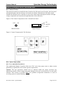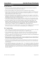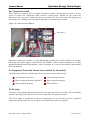
1
Quantum Energy Technologies Owners Manual WATER & POOL HEATERS OWNER’S MANUAL Including Installation Instructions and Warranty Information To Suit 67AC HEAT PUMP WATER, POOL & FLOOR HEATERS MODELS 67ACW2-134 67ACW2-134-C 67ACW-134 67ACW-134-C 67ACW-417 67ACW-417B 67ACP2-22 67ACP-407 67ACP-407-C 67ACP2-407 67ACB-407B 67ACB-417B Document Number: QDC0049PD-5 Date of Revision: July 2009 Document Number : QDC0049PD-5 Page 1 of 33 Owners Manual Quantum Energy Technologies Contents Section 1: APPLIANCE DETAILS ……………………………………………………..…..….….5 1a: Owner’s Details....................................................................................................................... 5 1b: Installer’s Details .................................................................................................................... 5 1c: Service History........................................................................................................................ 5 Section 2: INTRODUCTION ………………………………………………………………………6 2a: Model Code............................................................................................................................. 6 2b: General Description ................................................................................................................ 7 2c: Inspection on Delivery ............................................................................................................ 7 2d: Physical Data .......................................................................................................................... 7 2d.1: Physical Data Table........................................................................................................ 7 2d.2: Dimensions ..................................................................................................................... 8 Section 3: INSTALLATION ……………………………………………………………………….9 3a: Handling.................................................................................................................................. 9 3b: Location ................................................................................................................................ 10 3b.1: Unit Placement ............................................................................................................. 10 3b.2: Service Access.............................................................................................................. 10 3b.3: Clearances..................................................................................................................... 11 3b.4: Sound Isolation............................................................................................................. 11 3b.5: Vibration Isolation........................................................................................................ 11 3b. 6: Damper for Centrifugal Fan Models ........................................................................... 11 3c: Refrigerant Charge ................................................................................................................ 12 3d: Water System ........................................................................................................................ 12 3d.1: Water Piping................................................................................................................. 12 3d.2: Flow Switch.................................................................................................................. 13 3d.3: Water Connections ....................................................................................................... 13 3e: Condenser Water and Water Flow ........................................................................................ 13 3e.1: Water Flow ................................................................................................................... 13 3e.2: Water Heater Applications ........................................................................................... 13 3e.3: Pool Heater Applications.............................................................................................. 13 3e.4: Building Heater Applications ....................................................................................... 13 3f: Pool Heater ............................................................................................................................ 13 Document Number : QDC0049PD-5 Page 2 of 33 Owners Manual Quantum Energy Technologies 3g: Building Heating................................................................................................................... 14 3g.1: System Volume .................................................................................................................. 14 3g.2: Schematic of the heating system........................................................................................ 15 3h: Field Wiring .......................................................................................................................... 16 3h.1: Wire Sizing................................................................................................................... 16 3h.2: Electrical Data Table .................................................................................................... 16 3h.3: Wiring Diagram............................................................................................................ 17 Section 4: CONTROL LAYOUT AND OPERATION ……………………………………...…...19 4a: Control Centre....................................................................................................................... 19 4b: Control Operation ................................................................................................................. 19 4b.1: User Adjustable Parameters ......................................................................................... 19 4b.2. The Buttons ………………………………………………………………………...…20 4b.3. SET Button ……………………………………………………………………..….….20 4b.4: UP Button ………………………………………………………………………...…...20 4b.5: Down Button ……………………………………………………………………...…..20 4b.6 Programming Menu …………………………………………………………………...20 4b.7: Adjusting ……………………………………………………………………………...20 4b.8: Operating Principle……………………………………………………………………21 4b.9: Fault Codes …………………………………………………………………………...21 Section 5: OPERATION ……………………………………………………………………….....22 5a: Pre Start Up ........................................................................................................................... 22 5b: Commissioning ..................................................................................................................... 22 5c: Sequence of Operation .......................................................................................................... 23 5c.1: Start Up......................................................................................................................... 23 5c.2: Shut Down .................................................................................................................... 23 5d: Thermal Overload ................................................................................................................. 24 5e: Equipment Protection Alarms (not available for all models)................................................ 24 5f: De-icing ................................................................................................................................. 24 Section 6: MAINTENANCE……………………………………………………………………...25 6a: General .................................................................................................................................. 25 6b: Compressor ........................................................................................................................... 25 6b.1: Lubrication Oil ............................................................................................................. 25 6b.2: Operational Noise......................................................................................................... 25 6b.3: Frost on Sump .............................................................................................................. 25 Document Number : QDC0049PD-5 Page 3 of 33 Owners Manual Quantum Energy Technologies 6c: Refrigerant Sight Glass ......................................................................................................... 25 6d: Evaporator Fan...................................................................................................................... 26 6e: Electrical Terminals .............................................................................................................. 26 6f: Evaporator Coils .................................................................................................................... 26 6g: Operating Parameters............................................................................................................ 26 6h: Service Warnings .................................................................................................................. 27 6i: Thermostatic Expansion Valve.............................................................................................. 27 6j: Filter Drier ............................................................................................................................. 27 6k: Liquid Line Solenoid ............................................................................................................ 27 6l: Optional Controls................................................................................................................... 28 6l.1: Hot Gas Bypass (for 67ACW- 417 etc)......................................................................... 28 6m: Trouble Shooting ................................................................................................................. 28 6m.1: Trouble Shooting Chart ............................................................................................... 29 Section 7: WARRANTY DETAILS FOR 67AC HEATER UNITS……………………………...30 7a: Terms of Warranty ................................................................................................................ 30 7b: Items Not Covered By Warranty .......................................................................................... 31 7c: Before Phoning For Service .................................................................................................. 31 List of Figures Figure 1: Suggested Pushing Arrangement........................................................................................ 9 Figure 2: Suggested Lifting Arrangement ......................................................................................... 9 Figure 3: Clearance Requirements................................................................................................... 10 Figure 4: Typical in Field Condenser Water Piping ........................................................................ 12 Figure 5: Hydraulic Connection To Pool Heater ………………………………………………….13 Figure 6: The Schematic of the Heating System.............................................................................. 15 Figure 7a: Typical Field Wiring Diagram for Axial Fan ................................................................. 17 Figure 7b: Typical Field Wiring Diagram for Centrifugal Fan ....................................................... 17 Figure 8: The Control Components on the Left and Front Panel..................................................... 19 Figure 9: Control Components In The Enclosure ............................................................................ 19 Figure 10: Contactor Reset Button................................................................................................... 24 Figure 11: Sight Glass Moisture Indicator....................................................................................... 26 Document Number : QDC0049PD-5 Page 4 of 33 Owners Manual Quantum Energy Technologies Section 1: APPLIANCE DETAILS For future convenience, please fill in the following details and retain with your original invoice. 1a: Owner’s Details Surname : …………………………………… Given Name(s) : ….……………………….... Address : ……………………………………………………………………………...………… Town/Suburb : ……………………………………………………………………..…………… State/Territory : ……………………………… Postcode : …………………………………… Date of Purchase : .….……….……………… Purchased From : ………………………………………..………………………………….…… Model : ..…………………………………….. Serial Number : ………………..……………. Date of Manufacture: .……………………………………………………………….…………. (Details on Data Plate on water heater) 1b: Installer’s Details Date of Installation : ………………………… Installer’s Name : ………………………..….. Address : …………………………………….……………………………….…………….…… Installer’s Signature : …………………………………….………………….……………….…. 1c: Service History Date of Service : ............................................. Serviced By : …………….…………………. Work Carried Out : …………………….………………………………………………….……. Signature of Service Agent : .……………………………….………………………………….. Date of Service : ............................................. Serviced By : ……………….………………. Work Carried Out : …………………………………………………………….………………. Signature of Service Agent : .……………………………...……….………….……………….. Document Number : QDC0049PD-5 Page 5 of 33 Quantum Energy Technologies Owners Manual Section 2: INTRODUCTION Quantum Energy Technologies One of the World’s Most Energy Efficient Water Heating Methods We thank you for your decision to purchase a Quantum Energy Technologies Heat Pump Water Heaters, one of the most energy efficient water heaters available, which will reward you with many years of low energy hot water production. QUANTUM ENERGY TECHNOLOGIES Pty Ltd designs and manufactures energy efficient Heat Pump water heaters. The simple way to explain the advantage of this heater is that it saves energy in any weather, even at night. The heater may use 7kW of electrical energy; however, it is able to put up to 21kW of heat energy into the water @ 20°C ambient. The system can save up to 75% of conventional hot water energy utilisation; greatly assisting in the worldwide greenhouse gas reduction campaign. As the name indicates, a Heat Pump is a machine that pumps heat from a low temperature source to a high temperature reservoir. It has a cold side to absorb heat at low temperatures and a hot side to deliver heat at high temperatures. The Quantum system has an air coil as the cold side of the refrigeration circuit. This coil absorbs the heat from air that is forced through it by means of the fan. This is your assurance that you have purchased one of the highest quality water heaters on the market, one that will provide continuous hot water for all your needs - safely, economically, and for many years to come. Warranty Return Card Enclosed you will find a warranty card - please fill in the details and return immediately. This will ensure prompt service under warranty, if required. See section 7 for terms of warranty. 2a: Model Code 67 AC X -X-X B With Booster Fan type. Default for axial fan, and C for Centrifugal fan Refrigerant, e.g. R134a, R22, R407C and R417A, etc Heater and Heat exchanger type, e.g. W and W2 for Single and Double wall heat exchanger Water heaters respectively; P and P2 for Pool heaters without and with regulating valve, respectively; and B for Building heater Air Compact i.e. all in one – no split evaporator Compressor Nominal kW x 10 Document Number : QDC0049PD-5 Page 6 of 33 Quantum Energy Technologies Owners Manual 2b: General Description Quantum air compact water heaters are complete, self-contained automatic heat pump units. The units are completely assembled, factory wired, charged, and tested prior to delivery. Each unit consists of an air sourced fin coil evaporator, Copeland or equivalent scroll compressor, copper or Titanium condenser, and complete refrigeration piping. Liquid line components include filter/drier, sight-glass/moisture indicator, solenoid valve, and thermostatic or electronic expansion valve. Other features include de-icing device, compressor heater and liquid injection device(s) for overheat protection. The electrical control centre includes all equipment protection and operating controls necessary for automatic operation. Evaporator fan motors are started by their own contactors. They also have inherent overload protection. The compressor also has solid-state motor protection for inherent thermal overload protection. Protection: IPX4. 2c: Inspection on Delivery Check all items carefully against the bill of lading. Inspect all units for damage upon arrival. Report shipping damage or submit a claim to the carrier. Check the unit nameplate to be sure it agrees with the power supply available. Units are shipped FOB factory and Quantum is not responsible for physical damage after the unit leaves the factory. For unit shipping weights see section 2d.1: Physical Data Table. 2d: Physical Data 2d.1: Physical Data Table PHYSICAL DATA 67ACW2-134 67ACW2-134-C Compressor 67ACW-134 67ACW-134-C 67ACW-417 67ACW-417-C Copeland ZR108KCE-TFD or ZR108KC-TFD with oil recharge Nominal (kW) 6.7 kW Oil, Drain/Recharge (Litre) ICI EMKARATE RL 46H, 3.1/3.4 R134a Refrigerant Refrigerant Charge (kg) R417A 5.8 kg 4.6 kg Dimensions, WxDxH (mm) 5.8 kg 1250 x 1200 x 1510 mm Unit Shipping Weight (kg) 416 kg 442 kg 392 kg 408kg 392 kg 402 kg Optimal Water Flow (LPM) 70-90 70-90 80-100 80-100 80-120 80-120 DN40 Copper DN40 Copper DN40 Copper DN40 Copper DN40 Copper DN40 Copper 1725 kPa 1725 kPa 1725 kPa 1725 kPa Inlet/outlet Connections Max Water Pressure (kPa) 1725 kPa Duct Connection, WxD (mm) PHYSICAL DATA Compressor 600X500 mm 67ACP2-22 67ACP-407 ZR108KC-TFD 67ACP-407-C 67ACB-407B 67ACB-417B 6.7 kW Oil Drain/Recharge (Litre) Refrigerant Charge (kg) 67ACP2-407 600X500 mm Copeland ZR108KCE-TFD or ZR108KC-TFD with oil recharge Nominal (kW) Refrigerant 1725 kPa 600X500 mm ICI EMKARATE RL 32H, 3.1/3.4 R22 R407C R407C R417A 4.6 kg 4.6 kg 5.8 kg 5.8 kg 397 kg 397 kg Dimensions, WxDxH (mm) 1250 x 1200 x 1510 mm Unit Shipping Weight (kg) 382 kg Optimal Water Flow (LPM) 90-120 90-120 90-120 90-120 DN40 PVC DN40 PVC DN40 PVC DN40 PVC 1725 kPa 1725 kPa 1725 kPa 1725 kPa Inlet/outlet Connections Max Water Pressure (kPa) Duct Connection, WxD (mm) Document Number : QDC0049PD-5 380 kg 397 kg 382 kg 600X500 mm Page 7 of 33 Quantum Energy Technologies Owners Manual 2d.2: Dimensions 1121 1505 1425 Mo del No67ACW2-134-C Serial No SUZ0027 Date of MfgDec 2006 Hot Water Generating Rate542 l/h Heat ing C ap acit y22.10 kW Po wer In put (to tal)7.36 kW Typical Operatin g Amps15 Amps Max Amp s20 Amps Voltag e/H z/Phase 380- 420V / 50Hz /3Ph Co mpresso r6.70 kW ScrollCompressor OilICI EMKARATE RL 32H RefrigerantR134a Dimension ( Lengt hxDept hxHeight, mm) 1125x1120x1510mm Weig ht415 kgNote: Rated at 25oC amb ient,60oC. LIVE TERMINALS INSIDE TURE OFF POWER BEFORE OPENING COVER 1121 1225 360 1175 210 Models with Axial Fan 920 Clod Air Out Clod Air Out 1121 1505 1425 1500 Mo del No 67A CW2-134-C Serial No SUZ0027 Dat e o f Mfg Dec 2006 Hot Wat er G enerating Rate542 l/h Heating Capacity22.10 kW Po wer Inpu t ( tot al)7.36 kW Typical Operatin g Amps15 Amps Max Am ps20 Amps Volt age/Hz/Phase 380- 420V / 50Hz / 3Ph Co mpressor6.70 kW ScrollCompressor OilICI EMKARATE RL 32H RefrigerantR134a Dimensio n (L en gt hxDept hxHeight, mm) 1125x1120x1510mm Weight 415 kgNote: Rated at 25o C ambient,60oC. LIVE TERMINALS INSIDE TURE OFF POWER BEFORE OPENING COVER 1121 360 1225 1175 700 600 225 210 Models with Centrifugal Fan 600 920 Document Number : QDC0049PD-5 Page 8 of 33 Owners Manual Quantum Energy Technologies Section 3: INSTALLATION Trained, experienced personnel, who are familiar with local codes and regulations, especially concerning refrigerant release to the atmosphere, must perform installation. WARNING Sharp edges and coil surfaces can cause personal injury. Avoid contact with them. 3a: Handling Be careful to avoid rough handling of the unit. Do not push or pull the unit by anything other than the base. Block the pushing vehicle away from the unit to prevent damage to the sheet-metal cabinet and end frame (see Figure 1). To lift the unit, lifting slots are provided in the base of the unit. Arrange spreader bars and cables to prevent damage to the evaporator coils or cabinet (see Figure 2). Figure 1: Suggested Pushing Arrangement Blocking required across full width, 300mm Figure 2: Suggested Lifting Arrangement Spreader Bar (2) Pipe Slung Through Openings in Legs (2) Document Number : QDC0049PD-5 Page 9 of 33 Owners Manual 3b: Location Quantum Energy Technologies Figure 3: Clearance Requirements 3b.1: Unit Placement 1000mm Clearance for Air Inlet Units are for outdoor applications and can be mounted on a roof or at ground level. The location shall be dry and not subject to flooding at time. Set the unit on a solid and level foundation. For roof-mounted applications, install the unit on a steel channel or I-beam frame to support the unit above the roof. For ground level applications, install the unit on a substantial base that will not settle. A onepiece concrete slab with footings extending below the frost line is recommended. Additionally, the slab should not be tied to the main building foundations. Be sure the foundation is level (within 9 mm over its length and width). The foundation must support the weights listed in section 2d.1 Physical Data Table. It is preferable that the foundation has a 0.01 slope downward along the depth of the unit. 1200mm Clearance for Service Access 1200mm Clearance for Service Access 1000mm Clearance for Air Inlet The recommended minimum side clearance between two units is 2000mm. Since its operation is affected by wind, the unit should be located so that its length is parallel with the prevailing wind. If this is not practical, use field fabricated wind deflectors. 3b.2: Service Access Each end of the unit must be accessible after installation for periodic service. Compressor, filter drier, and liquid line solenoid valve are accessible from the side of the unit. Compressor, high-pressure, and low-pressure controls are from the front of the unit, and motor protector controls are on the compressor. Most operating, equipment protection, and starting controls are located in the unit control box. The fan deck with the evaporator fans and motors can be removed from the top of the unit. Document Number : QDC0049PD-5 Unit must not be installed in a pit or enclosure that is deeper or taller than the height of the unit unless extra space is provided. The minimum clearance on each side of the unit is 1200mm when installed in a pit. The pit cannot be deeper than the unit. The minimum clearance to a side wall or building taller than the unit is 2000mm provided no solid wall above 1800mm tall is closer than 3600mm to the opposite side of the unit. Page 10 of 33 Owners Manual Quantum Energy Technologies 3b.3: Clearances The flow of air to and from the evaporator coils must not be restricted. Restricting airflow or allowing air recirculation will result in a decrease in unit performance and efficiency and can lead to a malfunction. There must be no obstruction above the unit that would deflect discharge air downward where it could be re-circulated back to the inlet of the evaporator coil. The evaporator fan is a propeller type and will not operate with ductwork on the fan outlet. Install the unit with enough side clearance for air entrance to the coil and for servicing. Provide service access to the evaporator, compressor, electrical control panel and piping components as shown in Figure 3. Do not block access to the unit with piping or conduit. Do not block airflow from the top. Do not allow debris to accumulate near the unit. Air movement may draw debris into the evaporator coil causing air starvation. Give special consideration to low ambient operation where snow can accumulate. Keep evaporator coils and fan discharge free of snow or other obstructions to permit adequate airflow. 3b.4: Sound Isolation The sound level of the Quantum water heater is suitable for most applications. When additional sound reduction is necessary, locate the unit away from sound sensitive areas. Avoid locations beneath windows or between structures where normal operating sounds may be objectionable. Reduce structurally transmitted sound by isolating water lines, electrical conduit and the unit itself. Use wall sleeves and rubber isolated piping hangers to reduce transmission of water or pump noise into occupied spaces. Use flexible electrical conduit to isolate sound through electrical conduit. Spring isolators are effective in reducing the low amplitude sound transmission through the base for isolation in sound-sensitive areas (i.e. such as on the roof of a building). 3b.5: Vibration Isolation Vibration isolators are recommended for all roof-mounted installations or wherever vibration transmission is a concern. Installation of spring isolators requires flexible piping connections and at least one meter of flexible conduit to avoid straining the piping and transmitting vibration and noise. The unit should initially be placed on shims or blocks at the listed free height. When all piping, wiring, flushing, charging etc. is completed, the springs are adjusted upward to loosen the blocks or shims that are then removed. A rubber anti-skid pad under the unit can form part of the isolation. 3b.6: Damper for Centrifugal Fan Models Adjustable damper must be installed for each of the fan outlet for the centrifugal fan models to prevent the fan to be overloaded. Document Number : QDC0049PD-5 Page 11 of 33 Quantum Energy Technologies Owners Manual 3c: Refrigerant Charge All units are shipped with an operating refrigerant charge. The operating charge for each unit is shown in section 2d.1 Physical Data Table. 3d: Water System 3d.1: Water Piping Local authorities can advise the installer on the current building and safety codes required for proper installation. Install piping with a minimum of bends and changes in elevation to minimize pressure drop. Consider the following when installing water plumbing to the unit: 1. Vibration eliminators to reduce vibration and noise transmission to the building. 2. Shut off valves to isolate the unit from the plumbing system during unit servicing. 3. Manual or automatic air vents at the high points of the system. 4. Install drains at the lowest points in the system. 5. Maintaining adequate system water pressure to the water pump. 6. Temperature and pressure indicators located close to the unit to aid in unit servicing. 7. A strainer or other means of removing foreign matter from the water before it enters the pump. Place the strainer far enough upstream to prevent cavitations at the pump inlet. 8. A 40-mesh strainer is required just before the inlet of the condenser. This is important to prevent foreign material from entering and decreasing the performance of the condenser. 9. Flush the plumbing system thoroughly before the unit is connected. Perform regular water analysis and water treatment, as necessary, on the cold water line to the condenser. 10. Perform a preliminary leak check before insulating the plumbing pipe work and filling the system. Figure 4: Typical in Field Condenser Water Piping Air vent Outlet Condenser Isolation Service valve Inlet Strainer Service and Drain NOTES: 1. The by-pass valve and the dashed line is recommended for pool heating in case heater being isolated for servicing. 2. Support piping independently of the unit and install per local codes. Document Number : QDC0049PD-5 Page 12 of 33 Quantum Energy Technologies Owners Manual 3d.2: Flow Switch A flow switch is already installed on the water inlet line to shut down the unit if water flow is interrupted. The minimum flow rate required to close the switch is about 40LPM. 3d.3: Water Connections The inlet and outlet connections are copper, or PVC thread connections, respectively. The sizes of the connections are DN40mm. The water inlet and outlet are marked on the outside of the unit. 3e: Condenser Water and Water Flow 3e.1: Water Flow Condenser flow rate should fall between the minimum and maximum values shown in section 2d.1 Physical Data Table. Too high a flow rate outside of these limits will result in a lower temperature rise and a high pressure drop. Too low a flow rate will reduce the heat transfer and heat pump’s performance. 3e.2: Water Heater Applications It is imperative that the correct chemical balance be maintained in the water to be heated. As a guide the following parameters should be used: Calcium Hardness 70 - 150 mg/L 3e.3: Pool Heater Applications It is imperative that the correct chemical balance be maintained in your pool and/or spa water. Excessive sanitiser can damage your pool heater. As a guide the following parameters should be used: PH: Free Chlorine: 6.5 - 8.5 0.3 - 0.5 mg/L 3e.4: Building Heater Applications It is imperative that the correct chemical balance be maintained in your pool and/or spa water. As a guide the following parameters should be used: PH: Total Alkalinity: Calcium Hardness 7 - 10 80 - 120 p.p.m. 70 - 150 mg/L 3f: Pool Heater For the 67ACPX-X series (Pool Heater) although the units can also be installed directly into the existing filtration circuit, it is recommended to fit a by-pass circuit before the unit (see Figure 5). For pool heating, the heat exchanger MUST be installed before (up stream from) the sanitisation system not after (down stream) – see figures 5. This is to avoid high concentrations of sanitiser being passed through the heat exchanger, which may corrode it and void the warranty. Document Number : QDC0049PD-5 Page 13 of 33 Quantum Energy Technologies Owners Manual Figure 5: Hydraulic Connections To Pool Heater Showing shut-off by-pass valves (Optionally fitted by plumber to isolate the heater) Heated Water To Pool OUT Quantum Heater Unit CL Optional Shut-off By Pass IN FLT Cold Water From Pool All Pipes Are 40 mm PVC LEGEND Important Note Pool Heaters have an internal automatic by-pass system and do not require the external by-pass for operation. However, if desired, an external by-pass can be plumbed in for use if the heater is disconnected or to isolate it from the hydraulic circuit. In this way water would still flow but not through the heater unit. When the heater is in operation, this by-pass must not be used i.e. the 3 way valves must be set to channel the full flow through the heater unit and nothing via the external by-pass. Barrel Unions 3Way Isolating Valves (Optional) Water Circulation Pump Suggest 0.5 HP CL Chlorinator FLT Pool Filter 3g: Building Heating 3g.1: System Volume It is important to have adequate water volume in the system to provide an opportunity for the water heater to sense a load change, adjust to the change and stabilize. As the expected load change becomes more rapid, a greater water volume is needed. The system water volume is the Document Number : QDC0049PD-5 Page 14 of 33 Quantum Energy Technologies Owners Manual total amount of water in the condenser, air handling components (such as radiator panels or fan heater units) and associated piping. If the water volume is too low operational problems can occur including rapid compressor cycling, erratic refrigerant flow in the water heater, improper motor cooling, shortened equipment life and other undesirable symptoms. For normal comfortable heating, where the heating load changes relatively slowly, it is recommended a minimum system volume of five minutes times the flow rate (LPM). For example, if the design water heater flow rate is 120 LPM, a minimum system volume of 600 litres (120 LPM x 5 minutes). Since there are many other factors that can influence performance, systems may successfully operate below this suggestion. However, as the water volume decreases below this suggestion, the possibility of problems increases. 3g.2: Schematic of the heating system The Schematic of the heating system is shown in Fig 6. Figure 6: The Schematic of the heating system Expansion Tank Filling stop cock Water main Heat Pump Supply Check Valve Strainer Return Drain Water Pump Vibration isolator NOTES: 1. There must be a proper expansion tank in the system, and the bottom of the tank should be 500mm higher than the highest point of the hydraulic system. 2. The horizontal supply pipeline from the heater to the building must have 0.01 gradient to the heater, and at the highest point of the system, there must have an air vent (auto or manual). 3. The bottom edge of the expansion tank should be higher than the highest point of the hydraulic system by at least 500mm. 4. The volume of the expansion tank depends on the volume of the system. Roughly, for the 2.7kW and 6.7kW system, a normal 0.3m3 tank is required. 5. The expansion tank must be insulated properly unless it is fitted in the heated space. 6. If the water amount is not sufficient in the system, a storage tank could be required to prevent the short-cycle of the heat pump. Document Number : QDC0049PD-5 Page 15 of 33 Quantum Energy Technologies Owners Manual 3h: Field Wiring 3h.1: Wire Sizing Wiring must comply with all applicable codes and ordinances. Warranty is void if wiring is not in accordance with specifications. Copper wire is required for all power lead terminations at the unit. The units have single point power connection. A single field supplied fused disconnect is required. The control transformer is factory mounted. 3h.2: Electrical Data Table 67ACW-134/417 67ACW2-134 Single Point Power Supply Connection 67ACP-407 67ACP2-22 /407 Voltage Range (380-420V/50Hz/3Ph) Rated Load Amps (RLA) Locked Rotor Amps (LRA) 67ACW-417B 67ACW2-134-C 67ACB-407B 67ACP-407-C 67ACB-417B 342-456 342-456 342-456 24.2+ 24.2+ 36.4+ Recommended 30 30 45 Maximum 42 42 63 15.5 15.5 15.5 Minimum Circuit Amperage (MCA) Field Fuse Size or HACR Breaker Size 67ACW-134-C Compressor Fan 1.8 6.8 1.8 Compressor 111 111 111 Fan 6.5 24 6.5 NOTES: 1. Voltage within 10% of nameplate rating. 2. Phase imbalance within 3%. 3. Single conductors should be used for power connections. 4. Single point disconnect of electrical supply to the unit is required. This supply must be fused. 5. Field Fuse Size for recommended and maximum is based on the use of a time-delay fuse. 6. Compressor RLA values are for wire sizing purposes only and do not reflect normal operating current draw at rated capacity. 7. All terminal block connections must be made with copper (type THW) wire. 8. All field wire size values given in the table apply to 75°C rated wire. 9. Ampere correction factors must be applied for ambient temperatures in sizing the power lead wire. Refer to the local electrical code handbook. 10. For Heat Pumps fitted with optional Boosters, please refer to the equipment nameplate for maximum current draw, the circuit breaker, or similar device supplying the unit should be one current range above that of the equipment nameplate. Document Number : QDC0049PD-5 Page 16 of 33 Quantum Energy Technologies Owners Manual 3h.3: Wiring Diagram Figure 7a: Typical Field Wiring Diagram for Axial Fan Models FAN COMP 3N 50HZ/TN-S 380/220V PE QF1 L2 R S T KJ L1 KM2 FR1 L3 L1 KM1 N 16 Power(kW) Current(A) C 3~ V 3~ 7.06 0.48 1.8 24.22 De-ice RUN Neutral N YV Red14 N Red 13 EH DIV LIV COMP FAN WP Red 11 0 1 LP/HP 3~5A Current Sensor FUSE Line 5 FM1 FR1 Fan ST4 Comp QUANTUM ELECTRONIC CONTROL De-ice Liq-inj ST2 ST3 Red 12 7 8 9 Comp,Fan and LP/HP Protection Flow switch 4 Comp De-ice Air SET ST1 Booster 1 2 3 Sensors Water UP DOWN L 15 16 SB KJ L1 Red YV KM1 KM2 YV YV Black Document Number : QDC0049PD-5 Page 17 of 33 Quantum Energy Technologies Owners Manual Figure 7b: Typical Field Wiring Diagram for Centrifugal Fan Models FAN COMP 3N 50HZ/TN-S 380/220V PE QF1 L2 R S KJ L1 KM2 FR2 FR1 L3 L1 KM1 T 16 C 3~ Power(kW) Current(A) V 3~ 7.06 1.8 5.4 24.22 De-ice RUN Fan Comp Line 1 L d e R J K d e R 6 1 B 5S 1 d e R 4 1 3 1 2 1 N d e R L P W N Liq-inj P H / De-ice 3~5A Current Sensor FUSE N A F P M O C V I L V I D H E 4 5 Neutral P 7L 1 8F R 2 9F R Comp,Fan and LP/HP Protection Flow switch ST4 0 1 De-ice Air SET QUANTUM ELECTRONIC CONTROL Booster Comp 3 2 T 1 T T S S S 1 2 3 Sensors Water UP DOWN 2 M K 1 M K V Y V Y V Y k c a l B Document Number : QDC0049PD-5 Page 18 of 33 Quantum Energy Technologies Owners Manual Section 4: CONTROL LAYOUT AND OPERATION 4a: Control Centre The electrical controls are installed in three locations: the left panel (on/off switch), the front panel (the digital display) and the enclosure in side the unit cabinet. (Normally the left-hand section contains the microprocessor controller as well as the control input and output terminals. All high voltage components are located on the right hand side of the enclosure.) Figure 8: The Control Components on the Left and Front Panel OFF UP ON DOWN SET Manual Switch Digital Display Figure 9: Control Components In The Enclosure 4b: Control Operation 4b.1: User Adjustable Parameters The sophisticated Digital Controller allows the 67AC series heat pump owner to adjust certain parameters to optimise the unit for their specific requirements. Caution: The user parameters should only be adjusted within the ranges specified; any adjustments outside of these ranges may cause damage to the unit, and will not be covered under warranty. This section is provided ONLY for qualified refrigeration technicians to assist in servicing, repairs or trouble shooting. Document Number : QDC0049PD-5 Page 19 of 33 Owners Manual Quantum Energy Technologies 4b.2: The Buttons Use in conjunction with the Layout Diagram Fig 6 and Wiring Diagrams Fig 7&8. 4b.3: SET Button a) To enter the settings node, press the SET button 3 times; the display will show H60 (or H26) for water heaters (or pool heaters), this is the water temperature cut out set point. Pressing the UP or DOWN button will adjust the set point from 10°C to a maximum setting of 90°C for water heaters (or from 20°C to a maximum setting of 40°C for pool heaters or 55°C for building heaters). b) Press & hold SET button for 6 seconds to enter the de-icing mode. c) If display shows “OFF” press & hold the SET button for 6 seconds to cancel this mode. (Note this may cause system malfunction so avoid using). 4b.4: UP Button a) To raise a setting after selecting the required programming mode as in Section 4b.3. b) Press 3 times to display Axx (the discharge temperature). Push again to display bxx (evaporator temperature) or again for Cxx (ambient temperature). c) During the time delay start period, press & hold for 3 seconds to force a compressor start. When the compressor is running, press & hold for 3 seconds to force a compressor shutdown. 4b.5: DOWN Button a) To lower a setting after selecting the required programming mode as in Section 4b.3. b) Press & hold for 3 seconds to simultaneously open the de-ice valve and liquid injection valve; the valves will close 10 seconds later. c) When compressor is running, press 3 times to display the Amperage being drawn Cxx. 4b.6: Programming Menu To restore the digital controllers factory settings, press the SET button and hold while turning the power onto the system. To exit any level press the SET button to cycle through all menu items until the controller returns to the water temperature display once again. 4b.7: Adjusting To enter any menu, ¾ press the SET button to select the item to be adjusted. ¾ Press Up and Down to do the adjustment. ¾ After finishing the adjustment, press the SET button again to confirm. The screen flashes once to indicate the adjustment has been updated successfully. ¾ Press the SET button again to enter the next menu or return. Document Number : QDC0049PD-5 Page 20 of 33 Owners Manual Quantum Energy Technologies 4b.8: Operating Principle At power on the compressor will start after the 10 min time delay (1st Level t10). When the water temperature reaches 60°C the compressor will be de-activated. As the water temperature drops below 52C (H60d08) and the compressor has not been in operation for at least 10 min (1st Level P10), the compressor will be activated. During compressor operation, when the discharge temperature goes above 90°C (2nd Level P90), the liquid injection will be activated. When the compressor temperature (Axx) drops below 80°C (2nd Level b80), the liquid injection will be de-activated. If the compressor temperature (Axx) goes above 98°C (2nd Level H98), the compressor will be deactivated and the error code E05 will be displayed. When the compressor temperature drops below 85°C (2nd Level L85), and the compressor has not been in operation for at least 10 min (1st Level d10), the compressor will be reactivated. As the compressor temperature goes above 105°C, the compressor will be de-activated and the error code E06 will be displayed. A manual reset is required. Only if the temperature, measured by the evaporator sensor, is below 0°C will the de-icing function operates. When the compressor has been operating for 45 min (1st Level F45) and the evaporator temperature is 8°C’s lower than the ambient temperature and this temperature difference lasts for 5min, de-icing is activated. During the de-icing time, the fan stops. When the evaporator temperature rises to 8°C (2nd Level F08) or the de-icing time has been more than 10 min (1st Level E10), de-icing is de-activated. When the current draw is greater than the present value and lasts for 6 seconds, the compressor is de activated and the error code E04 will be displayed, 10 minutes later the compressor will be re activated. If the overload occurs again the system is de activated and the error cod E06 will be displayed. A manual reset will be required or the power to the unit can be switched off and then on again to reset the system. NOTE: If there is no display in the screen after the power is supplied to the unit, it means the phase order is not right. Swap the connections of any two line wirings. 4b.9: Fault Codes E01 Water temperature sensor open or short circuit. Auto reset. E02 Discharge temperature sensor open or short circuit. Auto reset. E03 Evaporator temperature sensor open or short circuit. Auto reset. E04 Compressor overload protection. Auto reset the first time, manual reset the second time. E05 Compressor overheat protection (exceeding 98°C setting). reset. E06 Compressor overheat protection (exceeding 105°C). Manual reset. E07 Dual pressure& overheat relay protection. Auto reset. E08 Ambient temperature sensor open or short circuit (Optional). Auto reset. E09 Water Flow Switch. Auto reset. Document Number : QDC0049PD-5 Page 21 of 33 Owners Manual Quantum Energy Technologies Section 5: OPERATION 5a: Pre Start Up 1. The hot-water system should be flushed and cleaned. Proper water treatment is required to prevent corrosion and scale formation on the condenser. 2. Inspect all water piping for flow direction and correct connections at the condenser. 3. Open all electric disconnects and check all electric connections for tightness. Check unit power supply wiring for proper amperage and a minimum insulation temperature of 75°C. Check for proper phasing using a phase sequence meter. 4. Verify water temperature sensor is installed in the exiting water line (supply to a water tank or building) for water heaters and building heaters, and the entering water line for pool heaters. On all Quantum units the sensors are factory mounted. 5. Check that the voltage of the power supply to the unit is within ±10% of the nameplate rating. Verify all mechanical and electrical inspections have been completed according to local codes. 6. Turn on the controller via the on/off switch mounted on the left panel of the cabinet. The Digital Controller will display the current water outlet temperature (for building heaters and water heaters) and the inlet temperature (for pool heaters). This will energize the system. (If crankcase heater is equipped, wait at least 24 hours before starting up the unit.) 7. Open all water flow valves and start the hot water pump. Check all piping for leaks and vent the air from the condenser as well as from the system plumbing for a building heater. 5b: Commissioning 1. If the controller calls for heating, the unit will begin the start-up sequence. Please be aware that there is a 10-minute time delay, after activation, prior to a compressor start. 2. After running the unit for a short time, check the rotation of fans, and flashing in refrigerant sight glass. The refrigerant sight glass should be clear with a solid column of liquid visible. 3. Allow the compressor to run a short time, but at the same time be ready to stop it immediately if any unusual noise or adverse conditions appear. 4. With an ammeter, verify that each phase of the compressor and the fan(s) are within the RLA as listed under Electrical Data. Adjust the damper for the centrifugal fan system to ensure that the electrical current for each fan is less than 4 amps. 5. Check the system operating parameters such as the head pressure and the water temperature as well as the suction pressure and the ambient temperature. The pressures can be measured with manifold gauges. 6. Verify superheat temperature is in the range of 4°C – 7°C at about 10°C ambient. The superheat may be large, at low ambient temperatures for a TX valve, and at high ambient temperature for an Electronic Expansion Valve. The superheat for an Electronic Expansion Valve is determined from the suction temperature and the suction pressure measured by the gauge, not directly read from the controller. Document Number : QDC0049PD-5 Page 22 of 33 Owners Manual Quantum Energy Technologies The superheat is calculated as the difference between the temperature of the suction refrigerant and the saturated temperature corresponding to the suction pressure, as illustrated below: Suction temperature (measured) t: _____________ °C Suction Pressure (measured): _____________ kPa Saturated temperature (property table) tg: _____________ °C Superheat (calculated) t-tg: _____________ °C 5c: Sequence of Operation The following sequence of operation is typical. It can vary depending upon options. 5c.1: Start Up With the control circuit supply on, 220-240V power is applied through the control circuit fuse to the compressor crankcase heater (if applicable), the compressor motor protection and the primary of the 24V control circuit transformer. The 24V transformer provides power to the microprocessor controller. When a remote time clock, manual switch or the unit controller turns on the hot water pump, the flow switch will close once satisfactory flow rate is achieved. If the hot water temperature is below the stage-on temperature, and all equipment protection devices are closed, the unit will start. The controller will operate the unit in response to the water temperature, any reset signals that may be present and any equipment protection signals that may occur. 5c.2: Shut Down When the controller senses that the correct water temperature has been reached, the liquid line solenoid valve will be de-energized. The compressor, liquid injection solenoid valve 1, and the fan will be de activated, and the machine will be in the hysteresis state. The compressor crankcase heater will energize when the compressor is shut down (if applicable). The Machine can also be turned off via the on/off switch mounted on the left side of the cabinet. The digital controllers display will be off. Please be aware that turning the on/off switch to the position OFF does not cut the power to the unit. Be sure to isolate the unit from the power supply should any work be required inside any enclosure of the unit. Document Number : QDC0049PD-5 Page 23 of 33 Owners Manual Quantum Energy Technologies 5d: Thermal Overload The compressor contactor has an integral Thermal Overload. The thermal overload is factory preset to protect the compressor from excessive current draw. Should for any reason the compressor draw excessive current, the thermal overload will “trip” and remove the supply from the compressor. “Pushing” the reset button manually resets the thermal overload. Figure 10: Contactor Reset Button Reset Button Should the compressor continue to “trip” the thermal overload, turn off the machine, de-energise and isolate the power supply at the POINT OF SUPPLY. Please contact Quantum or its duly appointed and authorised representative, who will arrange for a service technician to check and/or repair the machine. 5e: Equipment Protection Alarms (not available for all models) The following conditions will shut down the unit and activate the alarm circuit: No condenser water flow Low evaporator pressure Phase voltage protection (Optional) High evaporator pressure Motor protection system Sensor failures 5f: De-icing From time to time during the units operation the fan may stop, this is not a fault. The unit actually entered a de-icing mode, which will de-ice the evaporators for optimal operation. The de-ice mode is dependent on numerous parameters for its activation such as evaporator temperature and the time interval, and hence is automatically activate as required. Document Number : QDC0049PD-5 Page 24 of 33 Owners Manual Quantum Energy Technologies Section 6: MAINTENANCE 6a: General On initial start-up and periodically during operation, it will be necessary to perform certain routine service checks. WARNING If a system failure occurs due to improper maintenance during the warranty period, Quantum will not be liable for costs incurred to return the system to satisfactory operation. 6b: Compressor 6b.1: Lubrication Oil The Oil used in the compressor is clear in colour. If the oil colour darkens or exhibits a change in colour or there are any particles present, this may be an indication of contaminants in the refrigerant system. An oil sample should be taken and analysed. The colour of the oil may be seen from the refrigerant sight glass. If contaminants are present, the system must be cleaned. 6b.2: Operational Noise The system does produce noise during operation however any unusual compressor noise or heavy vibrations may indicate a potential problem. A qualified and experienced refrigeration technician should be familiar with normal compressor noise and would be able to advise if the noise being produced is abnormal. 6b.3: Frost on Sump No frost should be present on the sump of the compressor. 6c: Refrigerant Sight Glass Observe the refrigerant sight glass weekly. A clear glass of liquid indicates adequate sub cooled refrigerant charge in the system and proper feed through the expansion valve. Bubbling refrigerant in the sight glass indicates the system is short of refrigerant charge, and the system should have leak detection carried out to ascertain where the refrigerant is leaking from prior to recharging. Sub cooling should be verified to prevent overcharging. Refrigerant gas flashing in the sight glass could also indicate an excessive pressure drop in the line, possibly due to a clogged filter drier or a restriction elsewhere in the system. The sight glass will also indicate the moisture condition corresponding to the indicated colour. If the sight glass does not indicate a dry condition after about 12 hours of operation (shows yellow in the centre spot), the refrigerant or oil should be tested for moisture. If there is too much moisture in the system, the refrigerant must be vacuumed from the unit. The oil and the drier must also be changed, and then new refrigerant added. Document Number : QDC0049PD-5 Page 25 of 33 Quantum Energy Technologies Owners Manual Figure 11: Sight Glass Moisture Indicator SIGHT GLASS (“green” colour in centre indicating dry refrigerant) 6d: Evaporator Fan No routine lubrication is required of the fan motor. The fan motor bearings are of the permanently lubricated type and require no lubrication. But attention needs to be paid to any abnormal fan noise. 6e: Electrical Terminals WARNING Electric shock hazard. Disconnect & tag out all sources of Power to the unit before continuing with following service or severe personal injury or death can result. Normal heating and cooling of the wires will cause terminals to loosen. Retighten all electrical power terminals every six months. 6f: Evaporator Coils No maintenance is normally required except the occasional removal of dirt and debris from the outside surface of the fins. Clean as often as necessary to keep the coil free from foreign matter. For cleaning use locally purchased foaming evaporator coil cleaners. Evaporator cleaners may contain harmful chemicals, be careful when using such cleaners. Care should be taken not to damage the fins during cleaning. All chemical cleaners should be thoroughly rinsed from the coils. 6g: Operating Parameters Regular inspections of the system should be performed to ensure that the operating current, temperatures and pressures are within specifications, and that the operating controls are set to the correct settings. Refer to the Operation chapter of this manual. NOTE In case of repeated activation of one or more safety devices or alarms it is necessary to analyze the problem in depth, find the cause and eliminate it. Document Number : QDC0049PD-5 Page 26 of 33 Quantum Energy Technologies Owners Manual 6h: Service Warnings WARNING Disconnect and tag out all power sources to the unit before doing any service inside. Failure to do so can cause severe personal injury or death. CAUTION Service on this equipment is to be performed by qualified service personnel with particular regard to regulations concerning release of refrigerant to atmosphere. Note: Repeated tripping of equipment protection controls must be investigated and corrected. 6i: Thermostatic Expansion Valve The expansion valve is responsible for allowing the proper amount of refrigerant to enter the evaporator and maintaining a constant superheat. (Superheat is the difference between refrigerant temperature as it leaves the evaporator and the saturation temperature corresponding to the evaporator pressure.) Typically, superheat should run in the range of 4°C to 7°C). The superheat setting can be adjusted by removing the cap at the bottom of the valve to expose the adjustment screw. Turn the screw clockwise (when viewed from the adjustment screw end) to increase the superheat setting and counter clockwise to reduce superheat. Allow time (at least 15min) for the system to rebalance after each superheat adjustment. The expansion valve should not normally require replacement, but if it does, the unit must be pumped down by following the steps involved when changing a filter drier. If the problem can be traced to the power element only, unscrew the element from the valve body without removing the valve, but only after pumping the unit down. 6j: Filter Drier If the pressure drop across the filter drier is in the 40 to 70kPa range, it should be monitored and changed when the pressure drop reaches 70kPa. To change the liquid line sealed filter, de-energize the unit and pump out the refrigerant. After changing the filter drier, check for leaks before recharging and returning the unit to operation. 6k: Liquid Line Solenoid The liquid line solenoid valve does not normally require any maintenance. It may, however, require replacement of the solenoid coil. The solenoid coil may be removed from the valve body without opening the system, after disconnecting power to the unit. The coil can then be removed from the valve body by simply removing the nut or snap ring located at the top of the coil. Document Number : QDC0049PD-5 Page 27 of 33 Owners Manual Quantum Energy Technologies 6l: Optional Controls 6l.1: Hot Gas Bypass (for 67ACW- 417, 67ACP2-xxx, 67ACB-xxx) Hot gas bypass is a system for maintaining evaporator pressure at or above a minimum value. The purpose for doing this is to keep the velocity of the refrigerant, as it passes through the evaporator, high enough for proper oil return to the compressor when the ambient temperature is very low. The solenoid valve should be wired to open whenever the liquid line solenoid valve is energized. This can be accomplished by wiring the hot gas solenoid in parallel with the liquid line solenoid. The pressure control is factory set to begin opening at 200kPa. WARNING The hot gas line may become hot enough to cause injury in a very short time. Avoid contact during valve maintenance. 6m: Trouble Shooting WARNING Trouble shooting can present risks of severe personal injury or death from burns, cuts, electrocution, strangulation and asphyxiation. Troubleshooting must be done by trained, experienced technicians only. Document Number : QDC0049PD-5 Page 28 of 33 Quantum Energy Technologies Owners Manual 6m.1: Trouble Shooting Chart POSSIBLE CAUSES PROBLEM COMPRESSOR WILL NOT RUN COMPRESSOR NOISY OR VIBRATING EVAPORATOR COIL ICING UP COMPRESSOR THERMAL SWITCH OPEN HIGH DISCHARGE PRESSURE LOW SUCTION PRESSURE UNSTABLE SUCTION PRESSURE UNSTABLE DISCHARGE PRESSURE COMPRESSOR INTERVAL TOO SHORT MOTOR OVERLOAD RELAYS OPEN OR BLOWN FUSES POSSIBLE CORRECTIVE STEPS 1. Main switch open 2. Fuse blown, breakers open 1. 2. 3. 4. 5. 6. 7. 8. 9. Thermal overloads tripped Defective contactor or coil System off by protection device No heating required Liquid line solenoid will not open Motor electrical problem Loose wiring, faulty controller sensor / broken wire 10. Compressor failure 1. Refrigerant flooding compressor 2. Refrigerant overcharged 3. Improper line support 4. Worn compressor 1. Lack of refrigerant 2. Restricted air or cold air re-circulated 3. Expansion valve not opened sufficiently 4. Expansion valve power element leaks 5. De-ice interval too long for that particular site 6. Too much cold water to be heated 3. 4. 5. 6. 7. 8. 9. Close switch Check electrical circuits and motor windings for shorts. Check for overloads and loose connections. Replace fuse or reset breaker. Check unit when back on line, auto reset Repair or replace Determine cause and correct None, should start on call for heating Repair or replace coil Check motor for open or short circuit, or burnout Check all wire junctions. Tighten all terminals 10. 1. 2. 3. 4. 1. 2. 3. Replace compressor Check expansion valve setting and superheat Remove excess refrigerant Relocate or add supports Replace compressor Check for leaks. Repair and replace refrigerant. Proper clearance for air flow Check and adjust for proper superheat 4. Replace expansion valve 5. Shorten the de-ice interval 6. 1. Compressor loses oil owing to refrigerant flooding back 2. Compressor loses oil owing to refrigerant leaks 3. System contaminated, and/or Liquid injection capillary tube blocked 4. Suction superheat too high 5. Oil degrades owing to high temperature 1. 2. Reduce the amount of water or add a head pressure regulator to the machine Check and fix the flood back problem. Add oil if necessary Find and repair the leakage. Add oil if necessary 3. Purging the system and change oil and the filter/drier 4. 5. 6. 7. 1. 2. 3. 4. 5. 6. 1. 2. 3. 6. 7. 1. 2. 3. 4. 5. 6. 1. 2. 3. Adjust superheat Find and rectify the high discharge temperature. Change the oil (to the requirement amount!) purge the system and change the filter/drier Find and rectify the de-ice problem Replace crankcase heater Remove with authorized procedures Remove excess charge Check the settings Clean the tube Clean condenser Refer to ‘High Suction Pressure’ Check for leaks. Repair then replace refrigerant. Clean evaporator Replace filter drier 4. Check and change it 5. 1. 2. Check and adjust the de-icing setting if necessary. Check and close the valve for proper superheat Check and change the refrigerant and the drier 1. 2. Remove with authorized procedures Remove excess charge 1. Erratic water thermostat 2. Insufficient water flow 1. 2. Replace sensor Adjust flow 1. 2. 3. 4. 5. 6. 1. 2. 3. 4. 5. Check supply voltage Replace compressor Check all connections and tighten See steps for high discharge Too much refrigerant. Check the evaporator, the fan and the TX valve opening. Check voltage. Contact Power Company 4. 5. 1. 2. 1. 2. De-icing could not de-ice completely. Crankcase heater burned out Non condensibles in system Refrigerant overcharged Water temp cut-out setting too high Condenser water tube scaled Blocked condenser Higher suction pressure than normal Lack of refrigerant Evaporator dirty Clogged filter drier (pipe after the filter cold) Expansion valve malfunctioning (leakage phial/bulb) De-icing could not de-ice completely Expansive valve hunting Ice-blocking in the expansion valve (ice up in the Valve body) Non condensibles in system Refrigerant overcharged Low voltage during high loads Defective or grounded motor wiring Loose power wiring High evaporating temperature Liquid refrigerant flood back Unbalanced voltage 6. Document Number : QDC0049PD-5 Page 29 of 33 Owners Manual Quantum Energy Technologies Section 7: WARRANTY DETAILS FOR 67AC HEATER UNITS MANUFACTURED BY QUANTUM ENERGY TECHNOLOGIES PTY LTD 7a: Terms of Warranty QUANTUM ENERGY TECHNOLOGIES PTY LTD (the Company) WARRANTS “THIS QUANTUM ENERGY SYSTEM” (the unit) against faulty workmanship, materials and defects in manufacturing. THE 67AC HEATER CARRIES A TWO (2) YEAR LIMITED WARRANTY. Details as shown below. 1. Warranted for a period of two (2) years from the date of installation. This is limited to the evaporative fan coil and motor, heater cabinet, internal PVC piping and Unions. 2. Refrigeration pipe work, refrigeration valves, compressor, heat exchanger, electrical components including thermostats, solenoids, wiring and controls: - warranted for a period of two (2) years from date of installation. 3. Labour, delivery and / or transportation: - Where the Company considers it necessary to repair or replace any component part covered by the warranty, the consequential labour, delivery and / or transportation services will be provided free of charge to the owner within a fifty-kilometre radius from where the unit was purchased. Customers outside this area will be subject to freight and travelling charges incurred by the distributor carrying out the work. The date and time of the commencement of such warranty work will be at the discretion of the Company. Quantum does not warrant that such repair work will take place within any particular period. A call out fee applies to any warranty calls made outside normal QUANTUM business hours. The Company’s liability under this warranty shall be limited to the free replacement or repair of any defective component parts of the unit and shall not cover any consequential loss or damage arising out of any such defect. NOTE: Corrosion of the heat exchanger is caused by improper water quality / PH balance. Corrosion of this nature will void all warranties. THE WARRANTY SHALL NOT APPLY IN ANY OF THE FOLLOWING EVENTS: 1. 2. 3. 4. The Unit is installed by an installer not having adequate technical skills or training to perform the task; Where alterations, additions or repairs to the unit are carried out by persons unauthorised by the Company; Accident or in the opinion of the Company, misuse and / or abuse of the unit; Where the loss or damage is in the opinion of the Company due to the failure to install, operate and / or maintain the unit in accordance with any of the directions contained in the Owner’s Manual. THIS WARRANTY DOES NOT COVER LOSS OR DAMAGE TO THE UNIT OCCASIONED BY ANY OF THE FOLLOWING PERILS: 1. 2. 3. RIOT, CIVIL COMMOTION OR ANY CONSEQUENCE OF WAR OR INVASION. ACTS OF GOD. THEFT OR LARCENY. IMPORTANT This warranty is in addition to all other rights and remedies available to the consumer under the Trade Practices Act 1974 as amended and other relevant State and Territory laws and shall not be taken as applying to exclude, restrict or modify such rights or remedies in any manner whatsoever. Where the unit is of a kind not ordinarily acquired for personal, domestic or household use, then the liability of the Company for breach of any condition or warranty implied by the aforementioned statues (other than a condition or warranty implied by Section 69 of the Trade Practices Act or any corresponding Section on any other enactment in any State or Territory for the time being enforced) is limited to any one or more of the following as the Company decides: 1. 2. 3. 4. The replacement of the unit or the supply of an equivalent unit; The repair of the unit; The payment of the cost of replacing the unit or of acquiring an equivalent unit; The payment of the cost of having the unit replaced. Document Number : QDC0049PD-5 Page 30 of 33 Owners Manual Quantum Energy Technologies 7b: Items Not Covered By Warranty Service calls due to: • • • • • • Dirty Filters. Blown Fuses Incorrect Operation. Tripped Circuit Breakers. Main Isolator Switched Off. Blocked Drains (such as from the Evaporator etc). Failure to start due to voltage conditions or other damage due to inadequacy or interruption of electrical service. Damage caused by accident, misapplication, and abuse or tampering. Damage caused by use in a corrosive atmosphere (e.g. such as coastal regions). Filter cleaning and / or replacement, unless defective. Cleaning / maintenance of the water heater unit. Calls made to check the operation of a unit, which is found to be working satisfactorily. Remounting or relocating equipment due to ground subsidence. Modifications to system after installation due to changes in requirements. Relocation of equipment due to complaints of noise level or inappropriate location. No responsibility shall be accepted for damage to the system or property, if it is found that continued use of a faulty system has occurred. No responsibility shall be accepted for delays due to: • Unavailability of parts from suppliers. • Extreme delays due to unusually high demand for service. 7c: Before Phoning For Service Please check the following: • Have all the above mentioned items been checked and adhered to? • Have you read through all items in this manual? • Has the main isolation switch / circuit breaker / hot water switch been turned off? • Have any fuses in the switchboard blown? Warranty shall be carried out during normal business hours 08:00 hours (08:00 AM) to 16:30 hours (04:30 PM) Monday to Friday. Warranty covers travel within a 50-klm distance from the place of purchase, distributor or service agent’s premises. Any additional travel costs are at the expense of the customer. Document Number : QDC0049PD-5 Page 31 of 33 Owners Manual Quantum Energy Technologies Customer Notes: Document Number : QDC0049PD-5 Page 32 of 33 QUANTUM ENERGY TECHNOLOGIES PTY LTD 56-60 Bourke Road Alexandria NSW 2015 AUSTRALIA. A.B.N: 88 095 959 327 Phone: (+61 2) 9699 7444 Fax (61 2) 9699 5386 NOTE: While every care has been taken to ensure the accuracy in preparing this publication, No liability can be accepted for any consequences, which may arise as a result of its application. Quantum: A Hot Water Expert!