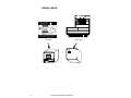
1
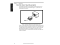
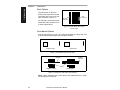
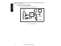
MS-520 Scan Head
User's Manual
P/N 83-000500 Rev E
Information and specifications in this manual are subject to change without notice.
Copyright © 2007
by Microscan Systems, Inc.,
1201 S.W. 7th Street, Renton, Washington, U.S.A. 98057
(425) 226-5700 FAX: (425) 226-8682
All rights reserved. The information contained herein is proprietary and is provided solely
for the purpose of allowing customers to operate and/or service Microscan manufactured
equipment and is not to be released, reproduced, or used for any other purpose without
written permission of Microscan.
Throughout this manual, trademarked names might be used. Rather than put a trademark (™) symbol in every occurrence of a trademarked name, we state herein that we
are using the names only in an editorial fashion, and to the benefit of the trademark
owner, with no intention of infringement.
Warranty Information
Microscan Systems, Inc. warrants products manufactured by it to be free from defects in
material or workmanship under normal use and service for a period of one year from date
of shipment.
This warranty is specifically limited to the replacement or repair of any such warrantable
defects, without charge, when the complete product is returned to Microscan Systems,
Inc., freight prepaid, at the address shown above. Contact the factory at the address
above for a Return Material Authorization (RMA) number before returning the product.
Microscan Systems, Inc. shall be the sole judge of the warrantability of alleged product
defects. Products that are returned for warranty examination and that are found to be
non-warrantable are chargeable and are returned freight collect. Upon request, an estimate will be provided before any chargeable repairs are attempted. A hard copy of a purchase order with the amount of the charge must be received by Microscan, either by mail
or by FAX, before any equipment is returned. Warrantable products are repaired or
replaced at no charge and returned freight prepaid.
THIS EXPRESS WARRANTY EXCLUDES ALL OTHER WARRANTIES, EXPRESS OR
IMPLIED, INCLUDING, BUT NOT LIMITED TO, IMPLIED WARRANTIES OF MERCHANTABILITY AND FITNESS FOR PURPOSE. MICROSCAN SYSTEMS, INC.,
SHALL NOT BE LIABLE FOR WARRANTY IN ANY AMOUNT EXCEEDING THE PURCHASE PRICE OF THE GOODS. MICROSCAN SYSTEMS, INC., SHALL NOT BE LIABLE FOR ANY SPECIAL, INCIDENTAL, OR CONSEQUENTIAL DAMAGES,
WHETHER IN CONTRACT, TORT, OR OTHERWISE.
The buyer acknowledges that he/she is not relying on the seller's skill or judgment to
select or furnish goods suitable for any particular purpose and that there are no warranties that extend beyond the description on the face hereof.
This warranty extends only to the original purchaser, and shall not apply to any products or
parts that have been subject to misuse, neglect, accident, or abnormal conditions or operations. Claims for damage in transit are directed to the freight carrier upon receipt.
ii
MS-520 Scan Head User’s Manual
Table of Contents
List of Illustrations .................................................................................. iv
List of Tables.......................................................................................... iv
About This Manual .................................................................................iv
Keystroke Entries ....................................................................................iv
Approvals ............................................................................................... v
Warning and Caution Summary ............................................................. v
Safety Labels .........................................................................................vi
Chapter 1
Introduction
MS-520 Scan Head Description........................................................... 1-2
FIS Options .......................................................................................... 1-3
Interfacing with Decoders .................................................................... 1-6
The Scanning System .......................................................................... 1-6
Chapter 2
Setup
Setup Goals ......................................................................................... 2-2
Label Orientation.................................................................................. 2-3
Tilt, Skew, and Pitch ............................................................................ 2-5
Object Detector Orientation ................................................................. 2-5
Read Ranges ....................................................................................... 2-6
Calculating the Number of Scans ........................................................ 2-8
Chapter 3
Installation
Mounting the Scan Head.......................................................... 3-2
Cabling ..................................................................................... 3-3
Operational Tips ....................................................................... 3-4
Appendices
Appendix A — Scan Head Specifications ............................................A-2
Appendix B — Optional Equipment .....................................................A-5
Appendix C — Glossary of Terms .......................................................A-7
Index ................................................................................................ I-1
MS-520 Scan Head User’s Manual
iii
List of Illustrations
Figure 1-1 Back View of MS-520 Scan Head Scanning a Label ............... 1-2
Figure 1-2 Laser Beam Spot Types (not to scale) ..................................... 1-4
Figure 1-3 Scan Beam Types, Side Views ................................................ 1-4
Figure 1-4 Single Line and Raster Scan Patterns ..................................... 1-4
Figure 1-5 Scan Head to Decoder Cabling ................................................ 1-6
Figure 1-6 System Diagram ....................................................................... 1-6
Figure 2-1 Ladder Orientation.................................................................... 2-3
Figure 2-2 Picket Fence Orientation .......................................................... 2-3
Figure 2-3 Angled Picket Fence Orientation .............................................. 2-4
Figure 2-4 Tilt, Skew, and Pitch Axes ........................................................ 2-5
Figure 2-5 MS-520 Scan Width and Range ............................................... 2-6
Figure 2-6 Label Dimensions ..................................................................... 2-8
Figure 2-7 Label Orientations .................................................................. 2-10
Figure 3-1 MS-520 Bottom Mounting Holes (full size) ............................... 3-2
Figure 3-2 Scan Head/Decoder Interface Cable ....................................... 3-3
Figure A-1 Mechanical Dimensions ........................................................... A-2
Figure A-2 MS-520 Bottom Mounting Plate (not full size) .......................... A-5
Figure A-3 Universal Stand......................................................................... A-6
List of Tables
Table 1-1 Available MS-520 Options (VLD)............................................... 1-3
Table 1-2 Available MS-525 Options (IR) .................................................. 1-3
Table 1-3 Raster Heights per Label Distance ............................................ 1-5
Table 2-1 MS-520 Read Ranges and Scan Widths ................................... 2-7
About This Manual
This manual provides complete information on setting up and installing the
MS-520 fixed-mount scan head.
Unless otherwise noted, this manual applies to the MS-525 infrared laser
beam scan head as well as the MS-520.
Keystroke Entries
Keystrokes to be entered from your terminal are highlighted in bold, as in
<D>, including a < left angle bracket symbol (unless redefined by Command
Start Character command) and followed by a > right angle bracket symbol.
iv
MS-520 Scan Head User’s Manual
Approvals
This equipment is approved for use by the following organizations:
• CDRH (Center for Devices & Radiological Health)
• UL (Underwriters Laboratories, Inc.)
• CSA (Canadian Standards Association)
• TüV (Technischer überwachungs-Verein) (MS-520 only)
Warning and Caution Summary
Note: The MS-520 scan head is designed to be connected to the MS-3000
decoder (single or dual). When installed, direct current power for the scan
head is provided by the deocder.
WARNING
Use of controls, adjustments, or performance of procedures
other than those specified herein may result in hazardous laser
light radiation exposure.
WARNING
Up to 5 mW of laser diode power can be present in the interior.
Avoid opening the scan head. Inspect housing to verify that
loose casings or panels do not allow access to laser light.
WARNING
The laser beam can be harmful to eyesight. Avoid direct eye
con tact with the laser beam. Never point the beam at other
people, or in a direction where people may be passing.
MS-520 Scan Head User’s Manual
v
Safety Labels
1201 S . W . 7th S t .
R enton, W A 98055
LIS TE D A C C E S S O R Y
R
U L 1 95 0
4K 68
CL AS S
FIS NU MB ER
SER IAL NU M BE R
M ANU FACT UR E D
M O DEL
P R O D U C T C O N F O R M S TO D H H S 2 1 C F R S U B C H A P TE R J.
U S E D W IT H M S - 30 00 D E C O D E R
+ 12V
50m A
P A T E N T N O . 5,2 39, 16 9
- 12V
35m A
+ 5V
240m A
11 -1 20 00 8 -0 1
Top Label
vi
MS-520 Scan Head User’s Manual
M A D E IN U S A
Back Label
Introduction
1
Chapter Contents
MS-520 Scan Head Description........................................................... 1-2
FIS Options .......................................................................................... 1-3
Interfacing with Decoders .................................................................... 1-6
The Scanning System .......................................................................... 1-6
Unless otherwise noted, this manual applies to the MS-525 scan head
(infrared laser beam) as well as the MS-520.
MS-520 Scan Head User’s Manual
1-1
1–Introduction
Chapter
1–Introduction
Chapter 1
Introduction
MS-520 Scan Head Description
The MS-520 scan heads use a high-speed, ten-sided spinning mirror to
direct laser beams across bar code labels (figure 1-1) and convert the
reflected light to waveforms.
To Microscan
decoder
Figure A-1 Back View of MS-520 Scan Head Scanning a Label
Figure 1-1 shows a MS-520 scan head in operation. Standard features of the
MS-520 include low power consumption, wide field of view, the ability to read
a complete range of code densities (from .0047 inch to .040 inch and larger,
depending on range option), at scan speeds of 330 scans per second.
Visible (MS-520 model) or infrared (MS-525 model) laser diode light wavelengths are available.
1-2
MS-520 Scan Head User’s Manual
FIS Options
FIS (Final Instruction Sheet) numbers are assigned to each customer order.
The MS-520 models are available in standard FIS options, listed in tables
1-1 and 1-2.
Table A-1 Available MS-520 Options (VLD)
Spot Type
Scan Beam
FIS-0520-0001
FIS #
Round
Single Line
Standard
Range
FIS-0520-0002
Round
Raster
Standard
FIS-0520-0003
Round
Single Line
UHDa
FIS-0520-0004
Round
Raster
UHD
FIS-0520-0009
Oval
Single Line
Standard
FIS-0520-0010
Oval
Raster
Standard
FIS-0520-0011
Oval
Single Line
UHD
FIS-0520-0012
Oval
Raster
UHD
a. Ultra High Density
Table A-2 Available MS-525 Options (IR)
FIS #
Spot Type
Scan Beam
Range
FIS-0525-0005
Round
Single Line
Standard
FIS-0525-0006
Round
Raster
Standard
FIS-0525-0007
Round
Single Line
UHD
FIS-0525-0008
Round
Raster
UHD
FIS-0525-0013
Oval
Single Line
Standard
FIS-0525-0014
Oval
Raster
Standard
FIS-0525-0015
Oval
Single Line
UHD
FIS-0525-0016
Oval
Raster
UHD
MS-520 Scan Head User’s Manual
1-3
1–Introduction
FIS Options
1–Introduction
Chapter 1
Introduction
Spot Options
The laser beam on the scan
head can be projected on the bar
code label as a round or an oval
spot, as shown in figure 1-2.
Oval
scan spot
Round
scan spot
An oval spot is recommended for
labels with voids, extraneous ink,
or other imperfections.
Figure A-2 Laser Beam Spot Types
(not to scale)
Scan Beam Options
Scan beams (figures 1-3 and 1-4) are projected either as a single line or as
a raster pattern, depending on the FIS option ordered.
Raster option
Single line option
Figure A-3 Scan Beam Types, Side Views
10 raster
scan lines
Scan line
Voids
Single line option
Raster option
Figure A-4 Single Line and Raster Scan Patterns
Note: Unless otherwise noted, laser beams are represented as a single
line throughout this manual.
1-4
MS-520 Scan Head User’s Manual
FIS Options
Scan beams projected across a label appear as a single scan line, as
shown on the left label in figure 1-4.
Raster Option
The raster option projects ten individual scan lines through 2 degrees of arc
with each rotation.
Table 1-3 shows estimated heights of raster images at selected scan
ranges, measured from the front of the scan head.
Table A-3 Raster Heights per Label Distance
Scan Range
Raster Height
2 inches (50.8 mm)
.10 inch (2.54 mm)
4 inches (101.6 mm)
.17 inch (4.32 mm)
6 inches (152.4 mm)
.24 inch (6.1 mm)
8 inches (203.2 mm)
.31 inch (7.87 mm)
10 inches (254 mm)
.38 inch (9.65 mm)
Range Options
All models are available in standard and ultra high density (UHD) optics.
See “Read Ranges” in chapter 2, “Setup” for specific range data.
Interfacing with Decoders
The MS-520 scan head consists of a scan head only. To decode and transmit bar code data, a separate series 3000 single (figure 1-5) or dual head
decoder is required (via an 8-pin modular cable). For information on configuration and decoder setup, see the decoder user's manual.
PWR
TRIG
SCAN
IND 1
IND 2
Figure A-5 Scan Head to Decoder Cabling
MS-520 Scan Head User’s Manual
1-5
1–Introduction
Single Line Option
1–Introduction
Chapter 1
Introduction
The Scanning System
Figure 1-6 shows a possible scanning system setup.
Bar-coded
item flow
Optional
monitor
MS-3000
or other
Microscan
decoder
Object
Detector
8-pin cable
To optional multidrop
concentrator
Power
pack
MS-520
Scan Head
Figure A-6 System Diagram
1-6
Host
MS-520 Scan Head User’s Manual
To 120/240 VAC
power supply
Chapter
Setup
2
2–Setup
Chapter Contents
Setup Goals ......................................................................................... 2-2
Label Orientation.................................................................................. 2-3
Ladder Orientation ....................................................................... 2-3
Picket Fence Orientation ..............................................................2-3
Angled Picket Fence Orientation ................................................. 2-4
Tilt, Skew, and Pitch............................................................................. 2-5
Object Detector Orientation.................................................................. 2-5
Read Ranges ....................................................................................... 2-6
Calculating the Number of Scans......................................................... 2-8
Ladder Calculation ....................................................................... 2-9
Picket Fence Calculation ............................................................. 2-9
Comparing Label Orientation Calculations ................................ 2-10
This chapter provides instructions for orienting the MS-520 scan head in
relation to labels, object detectors, read ranges, and ensuring a minimum
number of scans.
Careful evaluation of the specific application, including the number, type,
and location of scan heads, decoders, and object detectors, as required, is
a prerequisite to successful bar code scanning.
MS-520 Scan Head User’s Manual
2-1
Chapter 2
Setup
Setup Goals
To achieve the desired number of scans required by the application, scan
heads must be positioned so that the scan beam crosses a label within the
read range. To accomplish this, refer to the range table, bar code label orientations, scan calculations, and scan head orientation, as described in this
chapter.
In addition, a read rate test (see your decoder user’s manual) should be
performed to ensure that optimum scanning and decoding is occurring.
2–Setup
Determine the following before installation:
a. Label Orientation. Position the scan head and label so that the label
is given as many scans as possible. (Take into account, and adjust, if
necessary, label speed and/or the distance between bar-coded
objects.) Avoid angles that result in direct (specular) reflected light, or
blurring.
b. Object Detector Orientation. Position object detector (if used) so that
the detector senses the object before the scan head can read it, and
ensure that object detector light does not reflect back into the scan
head sensor.
c. Read Range. Position the scan head at a distance from the label that
is within the ranges specified by your application and verify ranges by
performing a read rate test.
d. Number of Scans. Ensure that each label receives the minimum
required number of scans for your application.
2-2
MS-520 Scan Head User’s Manual
Label Orientation
Label Orientation
If the bar code label bars are parallel to the direction of travel, as shown in
figure 1-1, the label is said to be in a ladder orientation; if the bars are perpendicular with the direction of travel, the label is said to be in a picket fence
orientation (figure 1-2).
Ladder Orientation,
Direction of label travel
2–Setup
In general, depending on label
size and speed, ladder orientation is preferable because different portions of the label are
scanned as the label goes by. In
addition label placement is not as
critical. As shown in figure 2-1, a
label can be can be successfully
read if placed anywhere within
the scan line.
Scan Line
Figure 2-1 Ladder Orientation
Picket Fence Orientation
Unlike ladder, picket fence
allows only a small portion of the
entire label to be scanned. As a
result, labels must be of good
quality since even slight label
imperfections such as extraneous ink, voids, etc., can cause
misreads or non-reads. (See figure 1-5 in chapter 1.)
Direction of label travel
Scan
Line
Figure 2-2 Picket Fence Orientation
Note: Either ladder or picket fence
can be rotated without losing its orientation, provided that the label’s direction
of travel does not change in relation to the scan line.
MS-520 Scan Head User’s Manual
2-3
Chapter 2
Setup
Angled Picket Fence Orientation
The problems associated with picket fence can be minimized by slightly tilting the scan line (figure 2-). This allows a larger portion of the label to be
scanned and increases the label placement area by “simulating” the ladder
orientation. This of course is impractical with a short bar code height.
2–Setup
Angled picket fence is recommended only where the bar
code is reasonably tall and the
label speed is not too fast in
relation to the scan field width,
since angling the label will
reduce the number of scans
on the label.
Direction of label travel
Scan Line
One advantage of the picket
fence over the ladder orientation is in the area of label
Figure 2-3 Angled Picket Fence Orientation
speed. In ladder mode, the
label travel distance is the
height of the bar code; in picket fence mode, the label can be read while it
travels the full distance of the scan width.
2-4
MS-520 Scan Head User’s Manual
Tilt, Skew, and Pitch
Tilt, Skew, and Pitch
Tilt refers to the label rotation,
relative to the scan head, as it
rotates on the tilt axis, as
shown in figure 2-4.
Skew Axis
Tilt
Axis
MS-520
Scan Head
Pitch
Axis
2–Setup
Skew refers to the angle of
the label, relative to the scan
head, as it rotates on the
skew axis, as shown in figure
2-4. MS-520 scan heads can
be skewed to a maximum of
±40 degrees from the centerline.
Bar Code
Label
Figure 2-4 Tilt, Skew, and Pitch Axes
Pitch refers to the position of
the label, relative to the scan head, as it rotates on the pitch axis. Maximum
pitch is ±50 degrees from the centerline. For the MS-520, pitch angles
between +3 and +5 degrees should be avoided since they may cause specular reflection, the return of direct, non-diffuse light.
Object Detector Orientation
Microscan products can be triggered from either a host or an object detector.
An object detector uses infrared light to detect the presence of a bar-coded
object and relays that information to the decoder, which will, if correctly configured, initiate a read cycle. Typically, a detector is positioned so that it will
detect the presence of an object before the object’s label can be scanned
by the scan head.
An object detector is mounted in any position relative to the object as long
as (1) the object passes within range of the detector and (2) direct or
reflected light from the detector beam does not interfere with the scan
head’s reception.
MS-520 Scan Head User’s Manual
2-5
Chapter 2
Setup
Read Ranges
A label must be within the read range—the zone, as measured from the
front of the scan head bezel, in which a label can be reliably read.
Scan Width
cm
15
in.
6
10
5
4
5
3
2
0
1
0
5
1
2
10
3
4
15
5
6
2–Setup
10
25
9
20
6
15
5
4
10
Infrared Laser
7
Visible Laser
8
3
2
5
1
MS-520
0
0
in.
cm
Range
Figure 2-5 MS-520 Scan Width and Range
Figure 1-5 shows the read ranges of visible and infrared MS-520 scan
heads. See table 1-4 for ranges and scan widths1 per label densities (narrow-bar-widths).
1. Scan Width is the distance across the scan beam in which a given label can be reliably read.
Scan width varies with read range. The greater the scan width, the longer a moving label will
be readable and the greater the number of expected scans.
2-6
MS-520 Scan Head User’s Manual
Read Ranges
Table 1-4 MS-520 Read Ranges and Scan Widths*
Maximum Scan
Width
Narrow-Bar-Width
Read Range
.0047” (.119 mm)
1.75–3” (45–76 mm)
3” (76 mm)
.0075” (.191 mm)
1–4” (25–102 mm)
4” (102 mm)
.0075” (.191 mm)
2–5” (51–127 mm)
4.75” (121 mm)
.010” (.254 mm)
1.5–6” (38–152 mm)
6” (152 mm)
.015” (.381 mm)
1–7” (25–178 mm)
7.5” (191 mm)
.020” (.508 mm)
1–9” (25–229 mm)
9.25” (235 mm)
.030” (.762 mm)
4–10” (102–254 mm)
9.5” (241 mm)
.040” (1.02 mm)
4–10” (102–254 mm)
9.5” (241 mm)
.050” (1.27 mm)
5–10” (127–254 mm)
9.75” (248 mm)
Visible Laser
UHD Range
Standard Range
UHD Range
Standard Range
*
.0047” (.119 mm)
1.75–3” (45–76 mm)
3” (76 mm)
.0075” (.191 mm)
1.25–3” (32–76 mm)
3.5” (89 mm)
.0075” (.191 mm)
2–4.5” (51–114 mm)
3.5” (89 mm)
.010” (.254 mm)
1.5–5” (38–127 mm)
4.75” (1.21 mm)
.015” (.381 mm)
1–6” (25–152 mm)
6” (152 mm)
.020” (.508 mm)
1–7” (25–178 mm)
7” (178 mm)
.030” (.762 mm)
4–9” (102–229 mm)
8.5” (216 mm)
.040” (1.02 mm)
4–9” (102–229 mm)
8.5” (216 mm)
.050” (1.27 mm)
5–9” (127–229 mm)
8.5” (216 mm)
Performance may vary slightly for raster units.
To achieve optimum performance with your application,
1. Configure the decoder for read rate mode.1
b. Temporarily position the scan head.
c. Map out a label placement area by manually moving your label in and
out and back and forth while observing read rates on the screen.
Read rates will vary due to differences in label quality, positioning, etc.
1. See the decoder user’s manual for read rate test information.
MS-520 Scan Head User’s Manual
2-7
2–Setup
Infrared Laser
Chapter 2
Setup
Calculating the Number of Scans
To ensure reliable scanning, it is recommended that a minimum of five
scans be applied to each label.
2–Setup
The number of scans that a given label will receive can be calculated by
formulas for both ladder and picket fence label orientations if the inputs
listed below are known.
• Scan Rate (SR) is the number
of scans per second that a
given scan head is capable of
Label length
emitting.
• Scan Width (SW) is the width
Label
across the scan beam, at a
height
given distance from the scan
head, in which a label can be
Quiet zones
read.
• Label Speed (LS) is the disFigure 2-6 Label Dimensions
tance per second that a label
moves as it travels through
the scan lines.
• Label Length (LL) (for picket fence formula only) is the length of the
longest printed label to be read plus the length of the quiet zones (figure
2-6).
• Label Height (LH) (for ladder formula only) is a measurement of the
height of individual bars (figure 2-6).
.
Note: Label length and label height are always measured as shown in figure
2-6, regardless of label orientation.
2-8
MS-520 Scan Head User’s Manual
Calculating the Number of Scans
Use the formula1 suitable for your application to predict the number of
scans each label will receive.
Ladder Calculation
(
LH x SR
LS
)
– 3 = number of complete scans
Example 1:
LH = 1 inch
2–Setup
LS = 10 inches per second
SR = 330 scans per second
(
1 x 330
10
)
– 3 = 30 complete scans
Picket Fence Calculation
(
(SW – LL) x SR
LS
Example 2:
)
– 3 = number of complete scans
LL = 1 inch (including quiet zones)
SW = 2 inches
LS = 10 inches per second
SR = 330 scans per second
(
(2 – 1) x 330
10
)
– 3 = 30 complete scans
Note: If the number of complete scans calculates out to less than the minimum required for your application, assign the desired value to the number of
complete scans and solve for any other parameter that can possibly be
changed, such as label length, scan width, or label speed.
1. The -3 component (in both formulas) is added to allow for the first and last scans, and an
AGC scan.
MS-520 Scan Head User’s Manual
2-9
Chapter 2
Setup
Comparing Label Orientation Calculations
When evaluating ladder versus picket fence orientations (figure 2-7), label
height, label length, and scan width are critical parameters.
Note that in both previous examples, a 1 inch square label yields the same
number of complete scans (30).
2–Setup
However, when label height or label
length are changed, the resulting number
of scans differs dramatically. For example, if both label height and label length
are decreased to 0.5 inch for both examples (figure 2-7), the ladder orientation
obtains 13 complete scans compared
with 46 scans in the picket fence orientation.
If label height and label length are both
increased to 1.5 inches, the ladder rate
goes up to 46 complete scans, compared
to 13 complete scans in picket fence.
Varying scan widths and label speeds will
also alter the number of scans.
Direction of Label Travel
Ladder
Orientation
Picket Fence
Orientation
Figure 2-7 Label Orientations
2-10
MS-520 Scan Head User’s Manual
Chapter
3
Installation
Chapter Contents
This chapter provides instructions for mounting the MS-520 scan head,
interfacing with a decoder, and initial operation.
Before permanently mounting the scan head, you should have read chapter 2, “Setup” and be confident that the scan head's mounting position
and orientation will allow it to read the application's labels at the maximum
read rate and with the desired number of scans.
MS-520 Scan Head User’s Manual
3-1
3–Installation
Mounting the Scan Head.......................................................... 3-2
Cabling ..................................................................................... 3-3
Operational Tips ....................................................................... 3-4
Chapter 3
Installation
Mounting the Scan Head
The MS-520 scan head can be mounted directly to a mounting surface of
your choice, or indirectly, via a mounting plate and a universal stand. (See
“Optional Equipment” on page A-5.)
To permanently mount the scan head:
1. Position the scan head in a dry place, devoid of sunlight, bright lights,
or light from other sources.
2. Before mounting, ensure sufficient clearance at the rear of the scan
head to allow for the 8-pin, RJ-45 connector and cable.
3–Installation
3. If not using the mounting plate, use the measurements provided in
figure 1-1 to locate centers of mounting holes and drill four 5/32 inch (4
mm) holes.
If using the mounting plate and a universal stand (see “Optional
Equipment” on page A-5), use the four perimeter holes for mounting
the plate and mount scan head directly to the four inner holes on the
plate.
4. Secure scan head with four 6-32 screws.
2.25" (57.15 mm)
1.40" (35.56 mm)
.43"
(10.92 mm)
.32"
(8.128 mm)
2.50"
(63.5 mm)
1.50"
(38.10 mm)
2.25"
(57.15 mm)
6-32 threads
(4 places)
Figure 3-1 MS-520 Bottom Mounting Holes (full size)
Caution: Do not allow the mounting screws to penetrate into the scan head
case more than .175 inch (4.4 mm) or damage to the scan head may result.
3-2
MS-520 Scan Head User’s Manual
Cabling
Cabling
The standard cable supplied with a MS-520 scan head is 6 feet (1.83 cm) in
length, wired with an 8-pin RJ-45 modular plug at each end.
1
1
8
8
Scan Head
+12 VDC in
-12 VDC in
Ground
+5 VDC in
Scan Sync out
Scan Head Disable in
Video (-) out
Video (+) out
Bare wire
3–Installation
1
2
3
4
5
6
7
9
Decoder
Figure 3-2 Scan Head/Decoder Interface Cable P/N: 61-130001-XX
Cables are also available in lengths from 1 to 15 feet, and are represented
by a cable part number. For example, if 01 is substituted for XX in part number (PN) 61-130001-XX in figure 1-2, then the cable length would equal 1
foot (30.5 cm).
To prevent voltage loss, cables between the decoder and scan head should
not exceed 15 feet (5.9 m) unless wire sizes exceed the minimum 26 AWG,
or power supply voltages at the scan head are verified to be within 8 percent.
MS-520 Scan Head User’s Manual
3-3
Chapter 3
Installation
Operational Tips
Do:
• Check the label for readability in the visible (670 nm) or infrared (780 nm)
range. If there is any question about the readability of the label, contact
your Microscan representative.
• Check inputs (label speed, length, height, etc.) to ensure the minimum
number of scans per label required for your application.
• As much as possible, avoid excessive tilt, pitch, and skew of the bar code
label.
• Test scan head readability with a label that is known to be good and log
the results.
• Clean the laser window on a regular basis with a clean, dry Q-tip or cotton
cloth, without using excessive force.
3–Installation
Do Not:
• Aim the scan head into sunlight, photo detectors, or other light-emitting
sources.
• Obstruct the laser window with mounting hardware or other objects.
• Connect chassis of scan heads, decoders, and host to different ground
potentials.
• Operate the scan head in excessive temperature environments (see
appendix A, “Scan Head Specifications”).
• Connect or disconnect scan head/decoder interface cable while decoder
power is ON.
3-4
MS-520 Scan Head User’s Manual
Appendices
Contents
Appendix A — Scan Head Specifications ............................................A-2
Appendix B — Optional Equipment .....................................................A-5
Appendix C — Glossary of Terms .......................................................A-7
Appendices
MS-520 Scan Head User’s Manual
A-1
Appendices
Appendix A — Scan Head Specifications
Except where otherwise noted,
the following specifications are
true for all MS-520 scan heads:
Physical
Length ............ 2.25 in. (57.15 mm)
Width............... 2.25 in. (57.15 mm)
Height.............. 2.25 in. (57.15 mm)
Cable Length... 6 ft. (183 cm) standard
Interface Connector RJ-45 8-pin
modular socket
Weight............. 8 oz. (227 g)
Scanning Parameters
Type ................ Rotating 10-sided
mirror
Scan Rate ....... Up to 330
scans per second
Scan Angle...... 60°
Pitch ................ ±50° maximum
Appendices
Skew ............... ±40° maximum
Figure A-1 Mechanical Dimensions
A-2
MS-520 Scan Head User’s Manual
Scan Head Specifications
Laser Light
Wavelength
Safety class
Operating life
Visible Laser
Infrared Laser
670 nm nominal
CDRH Class II
50,000 hrs. @ 25° C
780 nm nominal
CDRH Class I
400,000 hrs. @ 25° C
Optical
Composite read ranges for several Code 39 narrow-bar-width sizes at 2.5:1
wide-to-narrow bar ratios. See “Read Ranges” in chapter 2.
Operating Ranges
Visible
Standard
Range
UHD Range
1 to 10 in.
(2.54 to 25.4 cm)
1 to 4 in.
(2.54 to 10.16 cm)
Infrared
1 to 9 in.
(2.54 to 22.86 cm)
1.25 to 3 in.
(3.18 to 7.62 cm)
Scan Width ......................................8.5 inches at an 8-inch distance
Label Contrast:
Visible: 25% min. absolute dark/light differential at 670 nm
wavelength
Infrared: 40% min. absolute dark/light differential at 780
nm wavelength
Raster Image...................................10 raster scan lines over a 2-degree arc (or 0.24
inch raster at 6-inch distance)
(Compatible with Microscan series 3000 decoder.)
Port..................................................Socket for 8-pin RJ-45 modular
connector
Cabling ............................................6-foot cable standard, available in 1-foot increments to 15 feet
MS-520 Scan Head User’s Manual
A-3
Appendices
Decoder Interface
Appendices
Electrical
Power Requirements:
+12 VDC @ 50 mA maximum, 20 mV p-p maximum allowed ripple
-12 VDC @ 35 mA maximum, 20 mV p-p maximum allowed ripple
+5 VDC @ 240 mA maximum, 200 mV p-p maximum allowed ripple
Input Signals ................................... TTL high enable for laser-diode and motor (controlled by decoder software)
Output Signals:
Scan Sync: .... TTL level
Video Out: .... RS-422
Interface
8-pin RJ-45 modular connector
Pin Assignments:
Pin 1:
Pin 2:
Pin 3:
Pin 4:
Pin 5:
Pin 6:
Pin 7:
Pin 8:
+12 VDC in
–12 VDC in
Ground
+5 VDC in
Scan sync out
Scan Head Disable in
Video (–) out
Video (+) out
Environmental
Operating Temp.:
Visible:
Infrared:
32° to 104°F (0° to 40°C)
32° to 113°F (0° to 45°C)
Storage Temperature...................... –58° to 158° F (–50° to 70° C)
Appendices
Humidity .......................................... Up to 95% (non-condensing)
Ambient Light Immunity:
450 foot candles: ..... Indoor: fluorescent, incandescent,
mercury vapor, sodium vapor
2000 foot candles: ...... Soft outdoor
A-4
MS-520 Scan Head User’s Manual
Optional Equipment
Appendix B — Optional Equipment
Mounting Plate Kit
Part Number: 98-500002
To mount the scan head with the mounting plate, “pair up” the mounting
plate’s four inner screw holes to the scan head’s mounting holes (see figure
3-1 in chapter 3, “Installation”) and attach plate to scan head. Next, mount
entire assembly using the four outer holes on the plate.
3.3" (83.82 mm)
0.25" (6.35 mm)
2.1"
(53.34 mm)
Four countersunk holes, for
attaching plate to scan head
Four 0.156" (3.96 mm) Diameter
holes, used to mount plate to any
suitable surface
2.8" (71.12 mm)
Thickness of Plate =
0.1" (2.54 mm)
1.5"
(38.1 mm)
0.3"
(7.62 mm)
Appendices
Figure A-2 MS-520 Bottom Mounting Plate (not full size)
MS-520 Scan Head User’s Manual
A-5
Appendices
Universal Stand
The Microscan Universal Stand is available in 4-inch, 6-inch, and 10-inch
flex models as well as a 7-1/4" extension kit.
4-inch, knob adjustable handle
98-200008
6-inch, knob adjustable head and foot
98-200007
10-inch flax neck, adjustable head
98-200006
7-1/4-inch extension kit
98-200024
MS-520 Adapter plate
98-200011
4 inch Universal Stand
6 inch Universal Stand
10 inch Flex Neck
Universal Stand
Mates to adaptor plate
Ball joint
Adjust
knob
4"
10.16 cm
6"
15.24 cm
.25 "
.635 cm
10 "
25.40 cm
2"
5.080 cm
.190" DIA.
.483 cm DIA.
4 PL
2.5 "
6.350 cm
Appendices
.25 "
.635 cm
7-1/4-inch Universal
Extension Kit
Bottom
7.25"
18.42 cm
1.250 "
3.175 cm
1.125 "
2.858 cm
Figure A-3 Universal Stand
A-6
MS-520 Scan Head User’s Manual
.50 " DIA.1.270 cm
DIA. 3 Pl.
.20 " DIA.
.508 cm DIA.
3 PL
1.250 "
3.175 cm
C
L
1.125 "
2.858 cm
Glossary of Terms
Appendix C — Glossary of Terms
Bar Code. Data that has been encoded into an array of parallel bars and
spaces of varying widths.
Bar Code Density. Number of characters per inch or other unit of measure.
Decoder. A device that analyzes digital input provided by the scan head
and translates it into bar code information.
Focal Length. The distance measured from the scan head to the center of
the depth of field, or focal point.
Label Height. Regardless of orientation, the measurement taken along the
length of a bar.
Label Length. Regardless of orientation, the measurement taken across
the label's bars from one end to the other, including the quiet zone.
Label Speed. The rate in inches or centimeters per second that a label
moves through the scan beam.
Ladder Label Orientation. A bar code label in which the bars are parallel
to the direction of travel.
Mil. One thousandths of an inch or .0254 mm. In bar-coding, a measurement that identifies a bar code label by the width of its narrowest element.
Number of Scans Calculation. The number of times a bar code label is
scanned by the scan head during one pass through the laser beam.
Object Detector. A photo electric device used to sense the presence or
absence of an object.
Picket Fence Label Orientation. A bar code label in which the bars are
perpendicular to the direction of travel.
Pitch. Label (or scan head) rotation around the center of the pitch axis.
Port. An access point for data entry and exit.
Read Range. The distances in which a label can be reliably read, as measured from the front of the scan head.
Read Rate. The reading performance of the scan head for a given label
based on the percentage of good reads per a determined number of scans.
MS-520 Scan Head User’s Manual
A-7
Appendices
Oval Spot. An elongated laser beam involving custom optics that is
designed to project lengthwise with the label's bars and spaces.
Appendices
Round Spot. The standard laser beam as it appears on the label being
scanned, sometimes slightly ovalized.
Scan Head. The module that projects laser light on bar code labels and
receives reflected light back. This device changes the analog signal to a
digital representation of the bar code and outputs it to a decoder.
Scan Rate. Number of scan lines created by the scan head per second.
Scan Width. The measurement (inches or centimeters) of the scan beam
line at the readable scan range of a given application.
Skew. Label (or scan head) rotation around the center of the skew axis.
Specular Reflection. The direct, mirror-like reflection of laser light back to
the scan head, causing over-light saturation.
Tilt. Label (or scan head) rotation around the center of the tilt axis.
Trigger. A signal, either external or serial, that initiates the read cycle and
causes the decoder to expect label input.
Appendices
Wide-to-narrow Ratio. The ratio of the width of the widest (or wider) bar to
the narrowest bar of a given bar code symbology. For example, 2:1, 2.5:1,
3:1, and 4:1.
A-8
MS-520 Scan Head User’s Manual
Index
A
N
Ambient Light Immunity A-4
Angled Picket Fence Orientation 2-4
Approvals v
Number of Scans (setup objective) 2-2
C
Cable Length A-2
Cabling 1-6, 3-3
Calculating the Number of Scans 2-8
Caution Summary v
D
O
Object Detector Orientation 2-2, 2-5
Operating life A-3
Operating Ranges A-3
Operational Tips 3-4
Optional Equipment A-5
P
H
R
Height A-2
Humidity A-4
Installation 3-1
Interface Connector A-2
Interfacing with Decoders 1-6
Raster Height 1-5
Raster Image A-3
Raster Option 1-5
read cycle 2-5
Read Range (setup objective) 2-2
Read rate test 2-7
Reading Ranges and Scan Widths 2-7
L
S
Label Contrast A-3
Label Height 2-8
Label Length 2-8
Label Orientation 2-3
Label Speed 2-8
Ladder Orientation 2-3
Length A-2
Safety class A-3
Safety Labels vi
Scan Angle A-2
Scan Beam Options 1-4
Scan Rate 2-8, A-2
scan speed 1-2
Scan Width 2-8
Scanning System (diagram) 1-6
Setup Goals 2-2
Signals (input/output) A-4
Single Line Option 1-5
Skew 2-5, A-2
Skew (definition) A-8
specular reflection 2-5
F
I
M
Maximum pitch (±50) 2-5
Mounting Plate Kit A-5
Mounting the Scan Head 3-2
MS-520 Scanner User’s Manual
Index
FIS Options 1-3
Picket Fence Orientation 2-3
Pitch 2-5, A-2
Pitch (definition) A-7
Power Requirements A-4
Product Approvals. See Approvals
Decoder Interface A-3
I-1
Index
Spot Options 1-4
Standard features 1-2
T
Temperature A-4
Tilt 2-5
Tilt (definition) A-8
U
Universal Stand A-6
W
Index
Warning Summary v
Warranty Information ii
Wavelength A-3
Weight A-2
Width A-2
I-2
MS-520 Scanner User’s Manual