1
DG-BG4300N
300Mbps Wireless ADSL2/2+
Broadband Router
User Manual
V1.0
2011-12-01
As our product undergoes continuous development the specifications are subject to change without prior notice
DG-BG4300N User Manual
COPYRIGHT
Copyright © 2011 by this company. All rights reserved. No part of this publication may be
reproduced, transmitted, transcribed, stored in a retrieval system, or translated into any
language or computer language, in any form or by any means, electronic, mechanical,
magnetic, optical, chemical, manual or otherwise, without the prior written permission of this
company
This company makes no representations or warranties, either expressed or implied, with respect
to the contents hereof and specifically disclaims any warranties, merchantability or fitness for
any particular purpose. Any software described in this manual is sold or licensed "as is". Should
the programs prove defective following their purchase, the buyer (and not this company, its
distributor, or its dealer) assumes the entire cost of all necessary servicing, repair, and any
incidental or consequential damages resulting from any defect in the software. Further, this
company reserves the right to revise this publication and to make changes from time to time in
the contents thereof without obligation to notify any person of such revision or changes.
Trademarks:
DIGISOL™ is a trademark of Smartlink Network Systems Ltd. All other trademarks are the
property of the respective manufacturers.
DG-BG4300N User Manual
INDEX
1. Product Information ......................................................................................................... 6
1.1 Introduction and Safety Information .................................................................................. 6
1.2 Other features of the router .............................................................................................. 6
1.3 Safety Information ......................................................................................................... 7
1.4 System Requirements ..................................................................................................... 8
1.5 Package Contents ........................................................................................................... 8
1.6 Get Familiar with your new ADSL2+ Wireless broadband router ............................................ 9
2. System and Network Setup ............................................................................................. 11
2.1 Hardware Installation ................................................................................................... 11
3. Software Installation....................................................................................................... 13
4. Web Browser Configuration ............................................................................................. 22
5. Setup ............................................................................................................................ 27
5.1 WAN Configuration .................................................................................................... 27
5.1.1 ATM Settings ...................................................................................................... 29
5.1.2 ADSL Settings ..................................................................................................... 30
5.2 LAN Configuration ..................................................................................................... 32
5.2.1 LAN Interface Setup ............................................................................................ 32
5.2.2 DHCP Mode ........................................................................................................ 33
5.2.2.1 DHCP Server Configuration ........................................................................... 33
5.2.2.2 DHCP Relay Configuration ............................................................................ 34
5.2.3 DHCP Static Configuration ................................................................................... 35
5.2.4 LAN IPV6 Configuration ....................................................................................... 36
5.3 Wireless Configuration ............................................................................................... 40
5.3.1 Basic Setting ....................................................................................................... 40
5.3.2 Wireless Security Setup ....................................................................................... 41
5.3.3 Wireless Multiple BSSID Setup ............................................................................. 43
5.3.4 Wireless Access Control ....................................................................................... 44
5.3.5 Wireless Advanced Settings ................................................................................. 45
5.3.6 WPS ( Wi-Fi Pprotected Setup) ............................................................................ 48
6. Advanced Setup ............................................................................................................. 50
6.1 Route Setup .............................................................................................................. 51
6.1.1 Static Route Setup .............................................................................................. 51
6.1.2 IPv6 Routing Configuration .................................................................................. 52
6.1.3 RIP Configuration ............................................................................................... 53
6.2 NAT Configuration ..................................................................................................... 54
6.2.1 DMZ Setup ......................................................................................................... 54
6.2.2 Virtual Server ...................................................................................................... 55
6.2.3 NAT Forwarding Setup ......................................................................................... 58
6.2.4 NAT ALG and Pass-Through ................................................................................. 59
6.2.5 NAT EXCLUDE IP Setup ....................................................................................... 60
6.2.6 NAT Port Trigger ................................................................................................. 60
6.2.7 FTP ALG Configuration ........................................................................................ 61
6.2.8 NAT IP MAPPING ................................................................................................ 62
DG-BG4300N User Manual
6.3 QoS .......................................................................................................................... 63
6.3.1 IP QoS ............................................................................................................... 63
6.4 CWMP Setup ............................................................................................................. 65
6.4.1 TR-069 Configuration .......................................................................................... 65
6.5 Port Mapping Setup ................................................................................................... 67
6.5.1 Port Mapping Configuration ................................................................................. 68
6.6 Others ...................................................................................................................... 69
6.6.1 Bridge Setting ..................................................................................................... 69
6.6.2 Client Limit Configuration .................................................................................... 70
6.6.3 Tunnel Configuration ........................................................................................... 71
6.6.4 Other Advanced Configuration ............................................................................. 72
7. Service Setup ................................................................................................................ 73
7.1 IGMP Configuration ................................................................................................... 73
7.1.1 IGMP Proxy Configuration .................................................................................... 74
7.1.2 MLD Configuration .............................................................................................. 75
7.2 UPnP Setup ............................................................................................................... 77
7.2.1 UPnP Configuration ............................................................................................. 77
7.3 SNMP Setup .............................................................................................................. 78
7.3.1 SNMP Protocol Configuration ............................................................................... 78
7.4 DNS Setup ................................................................................................................ 79
7.4.1 DNS Configuration............................................................................................... 79
7.4.2 IPv6 DNS ............................................................................................................ 80
7.5 Dynamic DNS ............................................................................................................ 81
7.5.1 Dynamic DNS ( DDNS) Configuration .................................................................... 81
8. Firewall Setup ................................................................................................................ 83
8.1 MAC Filtering ............................................................................................................ 83
8.2 IP/Port Filtering Setup ............................................................................................... 84
8.2.1 IP/Port Filtering .................................................................................................. 84
8.2.2 IPv6/ Port Filtering .............................................................................................. 86
8.3 URL Filter ................................................................................................................. 87
8.3.1 URL Blocking Configuration ................................................................................. 87
8.4 ACL Setup................................................................................................................. 88
8.4.1 ACL Configuration ............................................................................................... 88
8.4.2 IPv6 ACL Configuration ....................................................................................... 89
8.5 DoS Setting .............................................................................................................. 90
9. Maintenance Setup ........................................................................................................ 91
9.1 Upgrade ................................................................................................................... 91
9.1.1 Upgrade Firmware .............................................................................................. 91
9.1.2 Backup/Restore Settings ...................................................................................... 92
9.2 Password .................................................................................................................. 94
9.2.1 User Account Configuration ................................................................................. 94
9.3 Reboot ..................................................................................................................... 95
9.3.1 Commit/Reboot ................................................................................................... 95
9.4 Time Setup ............................................................................................................... 96
9.4.1 System Time Configuration .................................................................................. 96
9.5 Log Setup ................................................................................................................. 97
9.5.1 Log Setting ......................................................................................................... 97
DG-BG4300N User Manual
9.6 Diagnostic Setup ....................................................................................................... 98
9.6.1 Ping Diagnostic ................................................................................................... 98
9.6.2 Ping6 Diagnostic ................................................................................................. 98
9.6.3 Traceroute Diagnostic .......................................................................................... 99
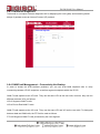
9.6.4 OAM Fault Management – Connectivity Verification ............................................... 99
9.6.5 ADSL Diagnostic................................................................................................ 100
9.6.6 Diagnostic Test ................................................................................................. 101
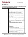
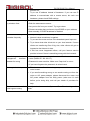
Troubleshooting ............................................................................................................... 102
DG-BG4300N User Manual
1. Product Information
1.1 Introduction and Safety Information
The DG-BG4300N supports Annex A mode. It provides four 10/100 Base-T Ethernet ports for user. The
device provides high-speed ADSL2+ broadband connection to the Internet or Intranet for high-end users,
such as net bars and office users.
It provides high performance access to the Internet, downstream up to 24 Mbps and upstream up to 1
Mbps. The device supports WLAN access to the Internet, such as WLAN AP or WLAN device. It
complies with IEEE 802.11b/g, IEEE 802.11n specifications, WEP, WPA, and WPA2 security
specifications.
You can configure the router by running the Setup Wizard in the CD-ROM provided in the package. The
wizard provides quick setup for Internet and Wireless connection. When you start the Setup Wizard,
Please follow the easy steps in Quick Installation Guide.
1.2 Other features of the router
High Internet Access throughput. Downstream at 24 Mbps and Upstream at 1 Mbps.
Wireless speed up to 300Mbps.
Allows multiple users to share a single xDSL internet connection.
Access private LAN servers from the internet.
Four wired LAN ports (10/100M) and one WAN port (RJ-11).
Works with IEEE 802.11b/g/n wireless LAN devices.
Supports IPv6.
Supports DHCP (Server/Client) for easy IP-address setup.
DG-BG4300N User Manual
1.3 Safety Information
In order to keep the safety of users and your properties, please follow the safety instructions as
mentioned below:
1. This router is designed for indoor use only; DO NOT place this router outdoor.
2. DO NOT place this router close to a hot or humid area, like kitchen or bathroom. Also, do not leave
this router in the car during summer.
3. DO NOT pull any connected cable with force; disconnect it from the router first.
4. If you want to place this Router at a height or mount on the wall, please make sure it is firmly secured.
Falling from a height would damage the router and its accessories and warranty will be void.
5. Accessories of this router, like antenna and power supply, are dangerous to small children.
KEEP THIS ROUTER OUT OF THE REACH OF CHILDREN.
6. The Router will get heated up when used for long time (This is normal and is not a malfunction). DO
NOT put this Access Point on paper, cloth, or other flammable materials.
7. There’s no user-serviceable part inside the router. If you find that the router is not working properly,
please contact your dealer of purchase and ask for help. DO NOT disassemble the router, warranty
will be void.
8. If the router falls into water when it’s powered, DO NOT use your hands to pick it up. Switch the
electrical power off before you do anything, or contact an experienced electrical technician for help.
9. If you smell something strange, or even see some smoke coming out from the router or power supply,
remove the power supply or switch the electrical power off immediately, and call dealer of purchase for
help.
DG-BG4300N User Manual
1.4 System Requirements
Notebook or desktop computer with network adapter (wired/wireless)
Internet connection, provided by xDSL or cable modem with a RJ-45 Ethernet port.
Web browser (Microsoft Internet Explorer 4.0 or above, Netscape Navigator 4.7 or above, Opera
web browser, or Safari web browser).
An available AC power socket (100 – 240V, 50/60Hz)
1.5 Package Contents
Before you start using this router, please check if there’s anything missing in the package, and contact
your dealer of purchase to claim for missing items:
DG-BG4300N ADSL2+ Wireless Broadband Router
Switching power adapter (9V DC, 1A)
Rubber feet (4 Nos.)
Quick Installation Guide
Installation software CD (includes User Manual, Utility)
Patch chord (1 No.)
DG-BG4300N User Manual
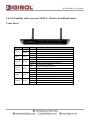
1.6 Get Familiar with your new ADSL2+ Wireless broadband router
Front Panel
LED
Power
Color
Red
Green
WPS
Green
WLAN
Green
LAN
(1~4)
Green
ADSL
Green
Internet
Green
Status
ON
OFF
ON
Blinking
OFF
ON
Blinking
OFF
ON
Blinking
OFF
ON
Blinking
OFF
ON
Blinking
OFF
Description
Device is initializing or initialization is failed
Power is OFF
Power is ON
WPS negotiation is enabled, waiting for the clients
WPS negotiation is not enabled on the device.
WLAN connection is normal.
Data is being transmitted or received.
Wireless is not enabled
LAN connection is normal.
Physical link is UP.
LAN port is not in use.
Physical link is UP.
ADSL handshaking process is ON.
No ADSL signal is being detected.
Internet connection is established.
Data is being transmitted or received.
Device is not connected to Internet.
DG-BG4300N User Manual
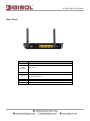
Rear Panel
Interfaces
Antenna
Radio
ON/OFF
WPS
Reset
LAN (1~4)
Line (WAN)
Power
Description
It is a 2dBi dipole antenna.
Switch the button to activate or deactivate the wireless
functions.
Press this button for less then 5 seconds to start WPS function.
Press this button and hold for 10 seconds to restore all settings
to factory defaults.
Local Area Network (LAN) ports 1 to 4.
(WAN / Internet) port. Connect ISP line to the Line port.
Power connector, connects to A/C power adapter.
DG-BG4300N User Manual
2. System and Network Setup
2.1 Hardware Installation
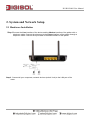
Step 1 Connect the Line interface of the device and the Modem interface of the splitter with a
telephone cable. Connect the phone set to the Phone interface of the splitter through a
telephone cable. Connect the input cable to the Line interface of the splitter.
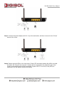
Step 2 Connect all your computers, network devices (switch / hub) to the LAN port of the
router.
DG-BG4300N User Manual
Step 3 Connect the power adapter (9V DC / 1A) to the wall socket, and then connect it to the ‘Power’
socket of the router.
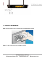
Step 4 Please check all LEDs on the front panel. Power LED ‘should be steadily ON, ADSL and LAN
should be ON. Check if the computer / network device connected to the respective port of the
router is powered ON and correctly connected. If power LED ‘P’ is not ON, or any LED you
expected is not ON, please recheck the cabling.
DG-BG4300N User Manual
3. Software Installation
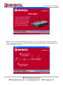
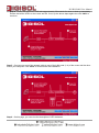
Step 1: Insert the Setup CD into your CD-ROM drive of notebook/desktop computer.
Step 2 : You will see the Autorun utilit. Click ‘Start’ to continue.
DG-BG4300N User Manual
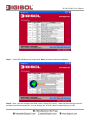
Step 3 : Connect one end of the telephone cable RJ-11 into the ADSL port provided on the splitter
from the service provider and connect other telephone cable from the splitter to the LINE port on the
router. Click ‘Next’ to continue.
DG-BG4300N User Manual
Step 4 : Power ON the router. It will take approximately 30 seconds for router to boot up completely.
Ensure that all the LED’s on the router are ON. If not, try the above steps again else click ‘Next’ to
continue.
Step 5 : Connect one end of the network cable to one of the LAN ports (1~4) of the router and the other
end to your computer. Click ‘Next’ to continue with the installation.
Step 6 : On this page, you can view the description of LED indicators.
DG-BG4300N User Manual
Step 7 : If the LED indications are proper click ‘Next’ to continue with the installation.
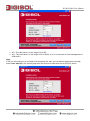
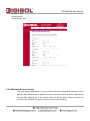
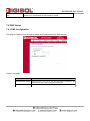
Step 8 : Here, you can configure the ADSL router. Select the Country : India and then select the service
provider from the drop-down list. You can change the VPI/VCI value as instructed by your ISP.
DG-BG4300N User Manual
VPI : The valid value is in the range of 0 to 255
VCI : The valid value is in the range of 32 to 65535. (0 to 31 is reserved for local management of
ATM traffic).
Note :
If ISP you are looking for is not listed in the dropdown list, then you can add the parameters manually,
select ‘User defined’ in the Country and enter the Service Provider with correct VPI/VCI values.
DG-BG4300N User Manual
Step 9 : Click ‘Next’ to continue with the installation.
You can select LLC or VC-Mux as the encapsulation mode according to the uplink equipment or use the
default setting.
1483 Bridged : If you select 1483 Bridged as the WAN protocol, you must use the third party
Dial-up software or Windows New Connection Wizard to configure the Internet dial-up access.
1483 MER : If you select 1483 MER as the WAN protocol, the router obtains an IP address
automatically.
1483 Routed : If you select 1483 Routed as the WAN protocol, you can not use the DHCP
service. You need to enter the IP address, subnet mask, default gateway and DNS that is
provided by your ISP.
PPPoE /PPPoA : If you select PPPoE or PPPoA as the WAN protocol, click Next, and the
following page appears.
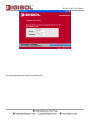
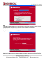
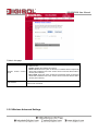
Step 10 : In this page, enter the correct user ID and password that is provided by your ISP.
After settings, click ‘Next’ to continue with the installation.
DG-BG4300N User Manual
Following page appears showing the WAN status.
DG-BG4300N User Manual
Note:
If the WAN IP address appears 0.0.0.0, then click Retry for retrying the connection to Internet. If a valid
IP address appears, other than 0.0.0.0, then click Finish to complete the configuration.
Click ‘Next’ to continue with the installation.
Step 11 : In this page, you can set the SSID for wireless network.
Step 12 : Click ‘Next’ and the following page appears. In this page, you can select WEP or WPA-PSK
/WPA2-PSK as the security mode. Enter 5 characters for WEP key. And enter 8~63 characters for WPA-
DG-BG4300N User Manual
PSK key. For more information about wireless security, refer to the user manual.
Step 13 : Click ‘Next’ and the following page appears. In this page, you can view the
configuration summary.
Step 14 : Click ‘Finish’ to save your settings and reboot the router.
DG-BG4300N User Manual
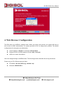
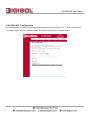
4. Web Browser Configuration
The DSL device is an ADSL2+ wireless router. When you power on the device, the system will boot up
and connect to ADSL automatically. The system provides a PVC for bridge test by default. The default
configurations for the system are listed below.
LAN IP address: 192.168.1.1, Netmask: 255.255.255.0
Default VPI/VCI for ATM (maximum 8 sets): 0/32, 1/32, 0/35
ADSL Line mode: Auto-detect.
User can change settings via WEB browser. The following sections describe the set up procedures.
Please set your PC’s Ethernet port as follow:
IP address: 192.168.1.XXX (e.g. 192.168.1.10)
Netmask: 255.255.255.0
DG-BG4300N User Manual
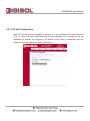
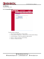
Access the Web Console:
Start your web browser.
Type the Ethernet IP address of the modem/router on the address bar of the browser. Default
IP address is 192.168.1.1.
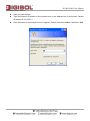
Enter Password in the dialog box when it appears. Default Username: admin Password: 1234
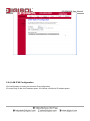
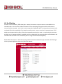
DG-BG4300N User Manual
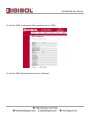
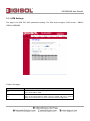
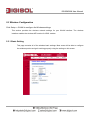
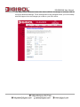
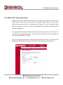
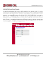
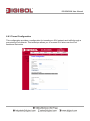
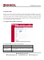
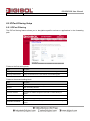
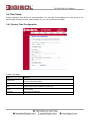
Once you have connected to ADSL2+ router. You will see the status page.
This page displays the ADSL modem/router’s current status and settings. This information is read-only
except for the PPPoE/PPPoA channel for which user can connect/disconnect the channel on demand.
Click the “Refresh” button to update the status
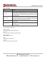
Function buttons in this page:
Connect / Disconnect
The two buttons take effect only when PVC is configured as PPPoE/PPPoA mode. Click
Connect/Disconnect button to connect/disconnect the PPP dial up link.
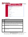
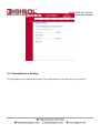
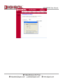
DG-BG4300N User Manual
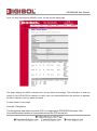
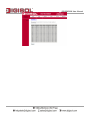
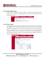
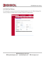
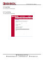
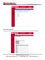
To view the ADSL Configuration Status please click on “ADSL”.
To view the ADSL Statistics please click on “Statistics”.
DG-BG4300N User Manual
DG-BG4300N User Manual
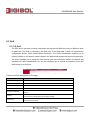
5. Setup
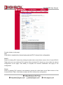
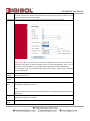
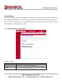
5.1 WAN Configuration
There are three sub-menu for WAN configuration: [Channel Config], [ATM Settings], and [ADSL
Settings].
Channel Config
ADSL modem/router supports 8 ATM Permanent Virtual Channels (PVCs). There are mainly three
operations for each of the PVC channels: add, delete and modify. And there are several channel modes
to be selected for each PVC channel. For each of the channel modes, the setting is quite different
accordingly. Please refer to the section – Channel Mode Configuration for further details.
DG-BG4300N User Manual
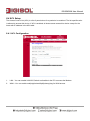
Function buttons in this page:
Add
Click Add to complete the channel setup and add PVC channel into configuration.
Modify
Select an existing PVC channel by clicking the radio button at the Select column of the Current ATM VC
Table before we can modify the PVC channel. After selecting PVC channel, we can modify the channel
configuration at this page. Click Modify to complete the channel modification and apply to the
configuration.
Delete
Select an existing PVC channel to be deleted by clicking the radio button at the Select column of the
Current ATM VC Table. Click Delete to delete this PVC channel from configuration.
DG-BG4300N User Manual
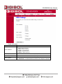
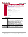
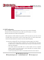
5.1.1 ATM Settings
The page is for ATM PVC QoS parameters setting. The DSL device support 4 QoS mode —CBR/rtVBR/nrt-VBR/UBR.
Fields in this page:
Field
Description
VPI
Virtual Path Identifier. This is read-only field and is selected on the Select column
in the Current ATM VC Table.
VCI
Virtual Channel Identifier. This is read-only field and is selected on the Select
column in the Current ATM VC Table. The VCI, together with VPI, is used to
identify the next destination of a cell as it passes through the ATM switch.
DG-BG4300N User Manual
QoS
Quality of Service, a characteristic of data transmission that measures how
accurately and how quickly a message or data is transferred from a source host
to a destination host over a network. The four QoS options are:
UBR (Unspecified Bit Rate): When UBR is selected, the SCR and MBS fields are
disabled.
CBR (Constant Bit Rate): When CBR is selected, the SCR and MBS fields are
disabled.
nrt-VBR (non-real-time Variable Bit Rate): When nrt-VBR is selected, the SCR
and MBS fields are enabled.
rt-VBR (real-time Variable Bit Rate): When rt-VBR is selected, the SCR and MBS
fields are enabled.
PCR
Peak Cell Rate, measured in cells/sec, is the cell rate which the source may
never exceed.
SCR
Sustained Cell Rate, measured in cells/sec, is the average cell rate over the
duration of the connection.
MBS
Maximum Burst Size, a traffic parameter that specifies the maximum number of
cells that can be transmitted at the peak cell rate.
Function buttons in this page:
Apply Changes
Set new PVC OoS mode for the selected PVC. New parameters will take effect after saving into flash
memory and reboot the system. See section “Admin” for save details.
Undo
Discard your settings.
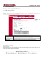
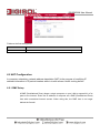
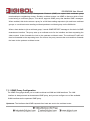
5.1.2 ADSL Settings
The ADSL setting page allows you to select any combination of DSL training modes.
DG-BG4300N User Manual
Fields in this page:
Field
Description
ADSL modulation
Choose prefered xdsl standard protocols.
G.lite : G.992.2 Annex A
G.dmt : G.992.1 Annex A
T1.413 : T1.413 issue #2
ADSL2 : G.992.3 Annex A
ADSL2+ : G.992.5 Annex A
AnnexL Option
Enable/Disable ADSL2/ADSL2+ Annex L capability.
AnnexM Option
Enable/Disable ADSL2/ADSL2+ Annex M capability.
ADSL Capability
“Bitswap Enable” : Enable/Disable bitswap capability.
“SRA Enable” : Enable/Disable SRA (seamless rate adaptation) capability.
DG-BG4300N User Manual
5.2 LAN Configuration
Click Setup -> LAN to configure the LAN Settings.
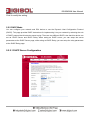
5.2.1 LAN Interface Setup
Following page shows the current setting of LAN interface. You can set IP address, subnet mask, and
IGMP Snooping for LAN interface in this page.
Fields in this
page:
Field
Description
IP Address
The IP address your LAN hosts use to identify the device’s LAN port.
Subnet Mask
LAN subnet mask.
IGMP Snooping
Enable/disable the IGMP snooping function for the multiple bridged LAN ports.
Function buttons in this page:
Apply Changes
Click to save the setting. New parameters will take effect after saving into flash memory and reboot the
system. See section “Admin” for save details.
DG-BG4300N User Manual
Modify
Click to modify the setting.
5.2.2 DHCP Mode
You can configure your network and DSL device to use the Dynamic Host Configuration Protocol
(DHCP). This page provides DHCP instructions for implementing it on your network by selecting the role
of DHCP protocol that this device wants to play. There are two different DHCP roles that this device can
act as: DHCP Server and DHCP Relay. When acting as DHCP server, you can setup the server
parameters at the DHCP Server page; while acting as DHCP Relay, you can setup the relay parameters
at the DHCP Relay page.
5.2.2.1 DHCP Server Configuration
DG-BG4300N User Manual
Fields in this page:
Field
Description
IP Pool Range
Specify the lowest and highest addresses in the pool.
Max Lease Time
The Lease Time is the amount of time that a network user is allowed to maintain
a network connection to the device using the current dynamic IP address. At the
end of the Lease Time, the lease is either renewed or a new IP is issued by the
DHCP server. The amount of time is in units of seconds. The default value is
86400 seconds (1 day). The value –1 stands for the infinite lease.
Domain Name
A user-friendly name that refers to the group of hosts (subnet) that will be
assigned addresses from this pool.
Subnet mask
A mask used to determine what subnet an IP address belongs to.
Default gateway
On a typical small home or office LAN, the existing routes that set up the default
gateway for your LAN hosts and for the DSL device provide the most appropriate
path for all your Internet traffic
DNS server
It is used to select the way to obtain the IP addresses of the DNS servers.
5.2.2.2 DHCP Relay Configuration
Some ISPs perform the DHCP server function for their customers’ home/small office
network. In this case, you can configure this device to act as a DHCP relay agent. When a
host on your network requests Internet access, the device contacts your ISP to obtain the
IP configuration, and then forward that information to the host. You should set the DHCP
mode to act as a DHCP relay.
DG-BG4300N User Manual
Fields in this page:
Field
Description
Relay Server
If you are using the other DHCP server to assign IP address to your hosts on the
LAN. You can set the DHCP server ip address.
5.2.
3 DHCP Static Configuration
Static DHCP is as useful feature which makes the DHCP server on your router always assign
the same IP address to a unique MAC address assigned to NIC.
Static IP is a manual way of obtaining an IP address for your computer, where the IP address is
pre-determined and always the same.
DG-BG4300N User Manual
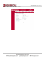
5.2.4 LAN IPV6 Configuration
IPv6 configuration is mostly the same as IPv4 configuration.
IPv4 uses only 32 bits for IP address space. IPv6 allows 128 bits for IP address space.
DG-BG4300N User Manual
Fields in this page:
Field
Description
Global
Address
Specify the IPv6 global address and prefix for the LAN interface.
Enable
Enable or disable the RA (Router Advertisement) function on the LAN side.
M Flag
Specify the “Managed address configuration” flag on Router Advertisement message. When set,
it indicates that addresses are available via Dynamic Host Configuration Protocol (DHCPv6).
O Flag
Specify the “Other configuration” flag on Router Advertisement message. When set, it indicates
that the other configuration information is available via DHCPv6. Example of such information is
DNS-related information or information on other servers within the network.
Max
The maximum time allowed between sending unsolicited multicast Router Advertisements from
Interval
the interface, in seconds.
Note:
The Max Interval must not be less than 4 seconds and not greater than 1800 seconds.
Min Interval The minimum time allowed between sending unsolicited multicast Router Advertisements from
the interface, in seconds.
Note:
The Min Interval must not be less than 3 seconds and not greater than 0.75 * Max Interval.
DG-BG4300N User Manual
The router will choose a random interval between max interval and minimum interval to send
unsolicited multicast Router Advertisement.
Prefix Mode Specify the prefix mode of the RA function. It can be set to either “Auto” or “Manual”.
When it set to “Auto”, the router will use the prefixes obtained from PD options for DHCPv6 on
WAN side to be placed in Prefix Information option in Router Advertisement; when it set to
“Manual”, the router will use the user specified prefix configuration in Router Advertisement.
On the “Manual” mode, user should also specify the “Prefix Address”, “Prefix Length”, “Preferred
Time” and “Valid Time”.
Prefix
Specify one prefix address for the router to advertise via Router Advertisement. The link-local
Address
prefix should not be set.
Prefix
Specify the prefix length of the prefix address.
Length
Preferred
Specify the preferred lifetime for this prefix address in the Prefix Information option on Router
Time
Advertisement message, in seconds.
Note:
The value of this field must not exceed the valid lifetime to avoid preferring addresses that are no
longer valid.
Valid Time
Specify the valid lifetime for this prefix address in the Prefix Information option on Router
Advertisement message, in seconds.
DHCP6
Mode
Specify the mode of the DHCPv6 server function. It can be set to “None”, “Auto” or “Manual”.
DG-BG4300N User Manual
When it set to “None”, the DHCPv6 Server function will be disabled on LAN side; when it set to
“Auto”, the router will use the prefixes and DNS obtained from PD options for DHCPv6 on WAN
side to generate the address pool; when it set to “Manual”, the router will use the user specified
pool prefix and DNS configurations.
On the “Manual” mode, user should also specify the “IPv6 Address Pool”, “Prefix Length”,
“Preferred Time”, “Valid Time” and “DNS Servers”.
IPv6
Specify the DHCPv6 address pool. It can be either a pool range or a single address.
Address
Pool
Prefix
Specify the prefix length of the addresses pool.
Length
Preferred
Specify the preferred lifetime for this prefix address, in seconds.
Time
Valid Time
Specify the valid lifetime for this prefix address, in seconds.
DNS
Specify the IPv6 address for the DNS servers.
Servers
DG-BG4300N User Manual
5.3 Wireless Configuration
Click Setup -> WLAN to configure the Wireless settings.
This section provides the wireless network settings for your WLAN interface. The wireless
interface enables the wireless AP function for ADSL modem.
5.3.1 Basic Setting
This page contains all of the wireless basic settings. Most users will be able to configure
the wireless portion and get it working properly using the setting on this screen.
DG-BG4300N User Manual
Fields in this page:
Field
Description
Disable Wireless LAN Interface
Check it to disable the wireless function for ADSL modem.
Band
Select the appropriate band from the list provided to correspond with your
network setting.
Mode
The selections are: AP
SSID
The Service Set Identifier (SSID) or network name. It is case sensitive and
must not exceed 32 characters, which may be any keyboard character.
The mobile wireless stations shall select the same SSID to be able to
communicate with your ADSL modem (or AP).
Channel Number
Select the appropriate channel from the list provided to correspond with
your network settings. You shall assign a different channel for each AP to
avoid signal interference.
Radio Power (mW)
The maximum output power: 15mW, 30mW or 60mW.
Channel Width
20MHz bandwidth : maximum Data rates = 150Mbps,
40MHz bandwidth : maximum Data rates = 300Mbps.
Associated Clients
It will show the Wireless clients currently associated with the ADSL modem
5.3.2 Wireless Security Setup
This screen allows you to setup the wireless security. Turn on WEP or WPA by using
encryption keys to prevent any unauthorized access to your WLAN.
DG-BG4300N User Manual
Fields in this page:
Field
Description
There are 4 types of security to be selected. To secure your WLAN, it’s strongly
recommended to enable this feature.
WEP: Make sure that all wireless devices on your network are using the
same encryption level and key. Click Set WEP Key button to set the
encryption key.
WPA (TKIP): WPA uses Temporal Key Integrity Protocol (TKIP) for data
encryption. TKIP utilized a stronger encryption method and incorporates
Encryption
Message Integrity Code (MIC) to provide protection against hackers.
WPA2 (AES):
WPA2, also known as 802.11i, uses Advanced
Encryption Standard (AES) for data encryption. AES utilized a symmetric
128-bit block data encryption.
WAP2 Mixed: The AP supports WPA (TKIP) and WPA2 (AES) for data
encryption. The actual selection of the encryption methods will depend on
the clients.
Check it to enable 802.1x authentication. This option is selectable only when the
“Encryption” is choose to either None or WEP. If the “Encryption” is WEP, you
Use 802.1x Authentication
need to further select the WEP key length to be either WEP 64bits or WEP
128bits.
DG-BG4300N User Manual
WPA Authentication Mode
There are 2 types of authentication mode for WPA.
WPA-RADIUS: WPA RADIUS uses an external RADIUS server to perform
user authentication. To use WPA RADIUS, enter the IP address of the
RADIUS server, the RADIUS port (default is 1812) and the shared secret
from the RADIUS server. Please refer to “Authentication RADIUS Server”
setting below for RADIUS setting. The WPA algorithm is selected between
TKIP and AES, please refer to “WPA cipher Suite” below.
Pre-Shared Key: Pre-Shared Key authentication is based on a shared
secret that is known only by the parties involved. To use WPA Pre-Shared
Key, select key format and enter a password in the “Pre-Shared Key Format”
and “Pre-Shared Key” setting respectively. Please refer to “Pre-Shared Key
Format” and “Pre-Shared Key” setting below.
PassPhrase: Select this to enter the Pre-Shared Key secret as user-friendly
textual secret.
Hex (64 characters): Select this to enter the Pre-Shared Key secret as
hexadecimal secret.
Pre-Shared Key Format
Pre-Shared Key
Specify the shared secret used by this Pre-Shared Key. If the “Pre-Shared Key
Format” is specified as PassPhrase, then it indicates a passphrase of 8 to 63
bytes long; or if the “Pre-Shared Key Format” is specified as Hex(64 characters),
then it indicates a 64-hexadecimal number.
Authentication
Server
RADIUS If the WPA-RADIUS is selected at “WPA Authentication Mode”, the port (default is
1812), IP address and password of external RADIUS server are specified here.
Function buttons in this page:
Apply Changes
Change the settings. New parameters will take effect after saving current config into flash
memory and reboot the system.
5.3.3 Wireless Multiple BSSID Setup
The SSID is a unique identifier that wireless networking devices use to establish and maintain
wireless connectivity. You can configure up to 4 SSIDs on your AP router and assign different
configuration settings to each SSID. All the SSIDs are active at the same time; that is, client
devices can associate to the access point using any of the SSIDs. These are the settings you can
assign to each SSID:
Enable VAP0~4
SSID
DG-BG4300N User Manual
broadcast SSID
Relay Blocking
Authentication Type
5.3.4 Wireless Access Control
This page allows administrator to have access control by entering MAC address of client
stations. MAC address can be added into access control list and only those clients whose
wireless MAC address are in the access control list will be either allowed or denied to
connect to the wireless AP as per the Access Control policy defined.
DG-BG4300N User Manual
Fields in this page:
Field
Wireless Access
Mode
MAC Address
Description
The Selections are:
Disable: Disable the wireless ACL feature.
Allow Listed: When this option is selected, no wireless clients except those
Control
whose MAC addresses are in the current access control list will be able to
connect (to this device).
Deny Listed: When this option is selected, all wireless clients except those
whose MAC addresses are in the current access control list will be able to
connect (to this device).
Enter client MAC address and press “Add” button to add client MAC address into
current access control list.
5.3.5 Wireless Advanced Settings
DG-BG4300N User Manual
This page allows advanced users who have sufficient knowledge of wireless LAN to
configure advanced settings. These setting shall not be changed unless you know exactly
what will happen from the changes you made on your DSL device.
DG-BG4300N User Manual
Fields in this page:
This value should remain at its default setting of 2346. It specifies the maximum size for a
packet before data is fragmented into multiple packets. If you experience a high packet error
rate, you may slightly increases the “Fragment Threshold” value within the value range of
256 to 2346. Setting this value too low may result in poor network performance. Only minor
modifications of this value are recommended.
Fragment
Threshold
This value should remain at its default setting of 2347. If you encounter inconsistent data
flow, only minor modifications are recommended. If a network packet is smaller than the
preset “RTS threshold” size, the RTS/CTS mechanism will not be enabled. The ADSL
RTS Threshold
modem (or AP) sends Request to Send (RTS) frames to a particular receiving station and
negotiates the sending of a data frame. After receiving an RTS, the wireless station
responds with a Clear to Send (CTS) frame to acknowledge the right to begin transmission.
Beacon
Interval
The Beacon Interval value indicates the frequency interval of the beacon. Enter a value
between 20 and 1024. A beacon is a packet broadcast by the ADSL modem (or AP) to
synchronize the wireless network. The default is 100.
Data Rate
The rate of data transmission should be set depending on the speed of your wireless
network. You should select from a range of transmission speeds, or you can select Auto to
have the ADSL modem (or AP) automatically use the fastest possible data rate and enable
the Auto-Fallback feature. Auto-Fallback will negotiate the best possible connection speed
between the AP and a wireless client. The default setting is Auto.
The Preamble Type defines the length of the CRC (Cyclic Redundancy Check) block for
communication between the AP and mobile wireless stations. Make sure to select the
Preamble Type
appropriate preamble type. Note that high network traffic areas should use the short
preamble type. CRC is a common technique for detecting data transmission errors.
Broadcast
SSID
If this option is enabled, clients can see the wireless network. This feature is intended to
allow clients to dynamically discover and roam between WLANs; if this option is disabled,
the device will hide its SSID. When this is done, the station cannot directly discover its
WLAN and MUST be configured with the SSID. Note that in a home Wi-Fi network, roaming
is largely unnecessary and the SSID broadcast feature serves no useful purpose. You
should disable this feature to improve the security of your WLAN.
Relay Blocking
When Relay Blocking is enabled, wireless clients will not associate with other wireless
clients.
Ethernet
Wireless
Blocking
When enabled, traffic between Ethernet and wireless interfaces are not allowed.
to
The DTIM Interval determines the number of AP beacons between each Delivery Traffic
Indication Message (DTIM). This informs clients of the next window for listening to broadcast
DTIM Interval and multicast messages. When the AP has buffered broadcast or multicast messages for
associated clients, it sends the next DTIM with a DTIM Interval value. Clients for that AP
hear beacons and awaken to receive the broadcast and multicast messages
For unicast transmissions, 802.11 implements layer2 acknowledgments and
WIFI Multicast
error checking to ensure frame delivery. Multicast traffic, on the other hand, has no link layer
to Unicast
error or loss management in the 802.11 standard.
Aggregation
Frame aggregation is a process of packing multiple MSDUs or MPDUs together to reduce the
overheads and average them over multiple frames, thus increasing the user level data rate.
Short GI
Guard Intervals (GI) are used to ensure that distinct transmissions do not interfere with one
another. Short GI enable = 400ns, disable = 800ns.
DG-BG4300N User Manual
5.3.6 WPS ( Wi-Fi Pprotected Setup)
Although home Wi-Fi networks have become more and more popular, users still have
trouble with the initial set up of network. This obstacle forces users to use the open
security and increases the risk of eavesdropping. Therefore, The Wi-Fi Protected Setup
(WPS) is designed to ease set up of security-enabled Wi-Fi networks and subsequently
network management.
The largest difference between WPS-enabled devices and legacy devices is that users do
not need the knowledge about SSID, channel and security settings, but they could still surf
in a security-enabled Wi-Fi network.
This device supports Push Button method and PIN method for WPS. The following subparagraphs will describe the function of each item. The webpage is shown below.
DG-BG4300N User Manual
Fields in this page:
Field
Description
Disable WPS
Check to disable the Wi-Fi protected Setup.
WPS Status
When AP’s settings are factory default (out of box), it is set to open security and
un-configured state. “WPS Status” will display it as “UnConfigured”. If it already
shows “Configured”, some registrars such as Vista WCN will not configure AP.
Users will need to go to the “Backup/Restore” page and click “Reset” to reload
factory default settings.
Self-PIN Number
“Self-PIN Number” is AP’s PIN. Whenever users want to change AP’s PIN, they
could click “Regenerate PIN” and then click “ Apply Changes”. Moreover, if users
want to make their own PIN, they could enter four-digit PIN without checksum
and then click “ Apply Changes”. However, this would not be recommended since
the registrar side needs to be supported with four-digit PIN.
Push Button Configuration
Clicking this button will invoke the PBC method of WPS. It is only used when AP
acts as a registrar.
Client PIN Number
It is only used when users want their station to join AP’s network. The length of
PIN is limited to four or eight numeric digits. If users enter eight-digit PIN with
checksum error, there will be a warning message popping up. If users insist on
this PIN, AP will take it.
Function buttons in this page:
Regenerate PIN
Click to regenerate the Self-PIN Number.
Start PBC
Click to start the Push Button method of WPS.
Apply Changes
Click to commit changes.
Reset
It restores the original values.
Start PIN
Click to start the PIN method of WPS.
DG-BG4300N User Manual
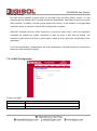
6. Advanced Setup
The end user can configure the Advance Setup
Route Configuration
The Routing page enables you to define specific route for your Internet and network data.
Most users do not need to define routes. On a typical small home or office LAN, the
existing routes that set up the default gateways for your LAN hosts and for the DSL device
provide the most appropriate path for all your Internet traffic.
On your LAN hosts, a default gateway directs all Internet traffic to the LAN port(s) on the
DSL device. Your LAN hosts know their default gateway either because you assigned it to
them when you modified your TCP/IP properties, or because you configured them to
receive the information dynamically from a server whenever they access the Internet.
On the DSL device itself, a default gateway is defined to direct all outbound Internet traffic
to a route at your ISP. The default gateway is assigned either automatically by your ISP
whenever the device negotiates an Internet access, or manually by user to setup through
the configuration.
DG-BG4300N User Manual
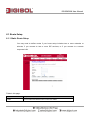
6.1 Route Setup
6.1.1 Static Route Setup
You may need to define routes if your home setup includes two or more networks or
subnets, if you connect to two or more ISP services, or if you connect to a remote
corporate LAN.
Fields in this page:
Field
Description
Enable
Check to enable the selected route or route to be added.
DG-BG4300N User Manual
Destination
The network IP address of the subnet. The destination can be specified as the IP
address of a subnet or a specific host in the subnet. It can also be specified as all
zeros to indicate that this route should be used for all destinations for which no
other route is defined (this is the route that creates the default gateway).
Subnet Mask
The network mask of the destination subnet. The default gateway uses a mask of
0.0.0.0.
Next Hop
The IP address of the next hop through which traffic will flow towards the
destination subnet.
Metric
Defines the number of hops between network nodes that data packets travel. The
default value is 0, which means that the subnet is directly one hop away on the
local LAN network.
Interface
The WAN interface to which a static routing subnet is to be applied.
Function buttons in this page:
Add Route
Add a user-defined destination route.
Update
Update the selected destination route under the Static Route Table.
Delete Selected
Delete a selected destination route under the Static Route Table.
Show Routes
Click this button to view the DSL device’s routing table.
6.1.2 IPv6 Routing Configuration
IPv6 configuration is mostly the same as IPv4 configuration (please refer to 6.1 Static Route
Setup). IPv4 uses only 32 bits for IP address space, IPv6 allows 128 bits for IP address space.
DG-BG4300N User Manual
6.1.3 RIP Configuration
RIP is an dynamic routing Internet protocol. Here you can set up to share routing table
information with other routing devices on your LAN, at your ISP’s location, or on remote
networks connected to your network via the ADSL line.
Most small home or office networks do not need to use RIP; they have only one router, such as
the ADSL Router, and one path to an ISP. In these cases, there is no need to share routes,
because all Internet data from the network is sent to the same ISP gateway.
You may want to configure RIP if any of the following circumstances apply to your network:
o
Your home network setup includes an additional router or RIP-enabled router (other than
the ADSL Router). The ADSL Router and the router will need to communicate via RIP to
share their routing tables.
o
Your network connects via the ADSL line to a remote network, such as a corporate
network. In order for your LAN to learn the routes used within your corporate network,
they should both be configured with RIP.
o
Your ISP requests that you run RIP for communication with devices on their network.
DG-BG4300N User Manual
Fields on the first setting block:
Field
Description
RIP
Enable/Disable RIP feature.
6.2 NAT Configuration
In computer networking, network address translation (NAT) is the process of modifying IP
address information in IP packet headers while in transit across a traffic routing device.
6.2.1 DMZ Setup
A DMZ (Demilitarized Zone) allows a single computer on your LAN to expose ALL of its
ports to the Internet. Enter the IP address of computer as a DMZ (Demilitarized Zone)
host with unrestricted Internet access. When doing this, the DMZ host is no longer
behind the firewall.
DG-BG4300N User Manual
Fields in this page:
Field
Description
Enable DMZ
Check this item to enable the DMZ feature.
DMZ Host IP Address
IP address of the local host. This feature sets a local host to be exposed
to the Internet.
6.2.2 Virtual Server
Firewall keeps unwanted traffic from the Internet away from your LAN computers.
Add a Virtual Server entry will create a tunnel through your firewall so that the
computers on the Internet can communicate to one of the computers on your
LAN on a single port.
DG-BG4300N User Manual
Fields in this page:
Field
Description
Service Type
Select a service from pull-down menu or User-defined Service Name.
Protocol
There are 2 options available: TCP, UDP.
WAN Setting
There are 2 options available: create rules by interface or by IP address
WAN Interface
Select the WAN interface on which the Virtual Server rule is to be
applied.
WAN Port
The destination port number that is made open for this application on
the WAN-side
Local IP Address
IP address of your local server that will be accessed by Internet.
LAN Open Port
The destination port number that is made open for this application on
the LAN-side.
Function buttons for the setting block:
Apply Changes
Click to save the rule entry to the configuration.
DG-BG4300N User Manual
Function buttons for the Current Table:
Delete Selected
Delete the selected rules from the table. You can click Delete button from the Current virtual serve
forwarding table.
Disable
Without deleting the rule you can make specific virtual server entry in the table as inactive. You can click
Disable to de-activate the entry.
DG-BG4300N User Manual
6.2.3 NAT Forwarding Setup
Entries in this table allow you to automatically redirect common network services to a specific machine
behind the NAT firewall. These settings are only necessary if you wish to host some sort of server like a
web server or mail server on the private local network behind your Gateway's NAT firewall.
DG-BG4300N User Manual
6.2.4 NAT ALG and Pass-Through
An application-level gateway (also known as ALG or application layer gateway) consists of a security
component that augments a firewall or NAT employed in a computer network. It allows customized NAT
traversal filters to be plugged into the gateway to support address and port translation for certain
application layer "control/data" protocols such as IPSec, L2TP, PPTP, FTP, SIP, RTSP etc. In order for
these protocols to work through NAT or a firewall, either the application has to know about an
address/port number combination that allows incoming packets, or the NAT has to monitor the control
traffic and open up port mappings (firewall pinhole) dynamically as required. Legitimate application data
can thus be passed through the security checks of the firewall or NAT that would have otherwise
restricted the traffic for not meeting its limited filter criteria.
DG-BG4300N User Manual
6.2.5 NAT EXCLUDE IP Setup
The purpose is to exclude certain flows of traffic from translation. Any packets (going from
inside or outside) matching the NAT EXCLUDE IP do not require NAT translation entries to be
permitted by the router.
6.2.6 NAT Port Trigger
Port triggering is a way to automate port forwarding in which outbound traffic on predetermined
ports ('triggering ports') causes inbound traffic to specific incoming ports to be dynamically
forwarded to the initiating host, while the outbound ports are in use. This allows computers
behind a NAT-enabled router on a local network to provide services that would normally
require the computer to have a fixed address on the local network. Port triggering triggers can
open an incoming port when a client on the local network makes an outgoing connection on a
predetermined port or range of ports.
DG-BG4300N User Manual
6.2.7 FTP ALG Configuration
Most FTP servers allow the capability of listening on a non standard control port other than
TCP 21. When the policy associated with this non standard port is configured with the
application ftp qualifier, as configured in the solution to this recipe, it dynamically open the
pinholes for the data channel for such FTP sessions.
DG-BG4300N User Manual
6.2.8 NAT IP MAPPING
Advanced users can use this feature for outgoing traffic, creating "NAT IP MAPPING" rules that
divert all traffic that is destined for a certain IP address to a different IP address.
Entries in this table allows you to configure one Global IP Pool for specified Local IP address
from LAN.
DG-BG4300N User Manual
6.3 QoS
6.3.1 IP QoS
The DSL device provides a control mechanism that can provide different priority to different users
or data flows. The QoS is enforced by the QoS rules in the QoS table. A QoS rule contains two
configuration blocks: Traffic Classification and Action. The Traffic Classification enables you to
classify packets on the basis of various fields in the packet and perhaps the physical ingress port.
The Action enables you to assign the strict priority level and mark some fields in the packet that
matches the Traffic Classification rule. You can configure any or all field as needed in these two
QoS blocks for a QoS rule.
Fields on the first setting block of this page:
Field
Description
IP QoS
Enable/Disable the IP QoS function.
Source IP
The IP address of the traffic source.
Source Netmask
The source IP Netmask. This field is required if the source IP has been entered.
Destination IP
The IP address of the traffic destination.
Destination Netmask
The destination IP Netmask. This field is required if the destination IP has been
entered.
Protocol
The selections are TCP, UDP, ICMP and the blank for none. This field is required if
the source port or destination port has been entered.
Source Port
The source port of the selected protocol. You cannot configure this field without
entering the protocol first.
DG-BG4300N User Manual
Destination Port
The destination port of the selected protocol. You cannot configure this field without
entering the protocol first.
Physical Port
The incoming ports. The selections include LAN ports, wireless port, and the blank
for not applicable.
Fields on the second setting block of this page:
Field
Description
Outbound Priority
The priority level for the traffic that matches this classification rule. The possible
selections are (in the descending priority): p0, p1, p2, p3.
IP Precedence
Select this field to mark the IP precedence bits in the packet that match this
classification rule.
IP Type of Service
Select this field to mark the IP TOS bits in the packet that match this classification
rule.
802.1p
Select this field to mark the 3-bit user-priority field in the 802.1p header of the
packet that matches this classification rule. Note that this 802.1p marking is
workable on a given PVC channel only if the VLAN tag is enabled in this PVC
channel.
DG-BG4300N User Manual
6.4 CWMP Setup
6.4.1 TR-069 Configuration
TR-069 is a protocol for communication between a CPE and Auto-Configuration Server
(ACS). The CPE TR-069 configuration should be well defined to be able to communicate
with the remote ACS.
DG-BG4300N User Manual
Fields in this page:
ACS Field
Description
URL
ACS URL. For example, http://10.0.0.1:80 https://10.0.0.1:443
User Name
The username the DSL device should use when connecting to the ACS.
Password
The password the DSL device should use when connecting to the ACS.
Periodic Inform Enable
When this field is enabled, the DSL device will send an Inform RPC to the ACS
server at the system startup, and will continue to send it periodically at an
interval defined in Periodic Inform Interval field; When this field is disabled, the
DSL device will only send Inform RPC to the ACS server once at the system
startup.
Periodic Inform Interval
Time interval in second to send Inform RPC.
Connection Request Field
Description
User Name
The username the remote ACS should use when connecting to this device.
Password
The password the remote ACS should use when connecting to this device.
DG-BG4300N User Manual
Path
The path of the device ConnectionRequestURL. The device
ConnectionRequestURL should be configured based on the Device_IP, Path
and Port as follows: http://Device_IP:Port/Path
Port
The port of the device ConnectionRequestURL.
6.5 Port Mapping Setup
The DSL device provides multiple interface groups. Up to five interface groups are supported
including one default group. The LAN and WAN interfaces could be included. Traffic coming from
one interface of a group can only be flowed to the interfaces in the same interface group. Thus, the
DG-BG4300N User Manual
DSL device can isolate traffic from group to group for some application. By default, all the
interfaces (LAN and WAN) belong to the default group, and the other four groups are all empty. It is
possible to assign any interface to any group but only one group.
6.5.1 Port Mapping Configuration
Fields in this page:
Field
Description
Enabled/Disabled
Radio buttons to enable/disable the interface group feature. If disabled, all
interfaces belong to the default group.
DG-BG4300N User Manual
“Interface groups
To manipulate a mapping group:
Select a group from the table.
Select interfaces from the available/grouped interface list and add it to the
grouped/available interface list using the arrow buttons to manipulate the
required mapping of the ports.
Click “Apply Changes” button to save the changes.
6.6 Others
6.6.1 Bridge Setting
You can enable/disable Spanning Tree Protocol and set MAC address aging time in this page.
Fields in this page:
Field
Description
DG-BG4300N User Manual
Ageing Time
Set the Ethernet address ageing time, in seconds. After [Ageing Time] seconds of
not having seen a frame coming from a certain address, the bridge will time out
(delete) that address from Forwarding DataBase (fdb).
802.1d Spanning Tree
Enable/disable the spanning tree protocol
6.6.2 Client Limit Configuration
This page is used to configure the capability of force how many devices can access to Internet!
DG-BG4300N User Manual
6.6.3 Tunnel Configuration
This configuration provides a configuration for tunneling an IPv6 network and traffic through a
pre-existing IPv4 network. This technique allows you to connect IPv6 sites over the IPv4
backbone that exists.
DG-BG4300N User Manual
6.6.4 Other Advanced Configuration
Here you can set other miscellaneous advanced settings.
Half Bridge:
When the PPP Half Bridge is enabled the WAN IP address from the ISP is passed straight through the
modem to the local client PC. Only one PC is able to access the Internet using half bridge mode as NAT
is disabled. Half bridge mode can only be used when a single IP address has been assigned by the ISP,
it is not suitable for services that provide multiple IP addresses. Half bridge mode is used when the use
of NAT or NAPT is not desired and there is a single computer attached to the modem. When the halfbridged modem is used in conjunction with a router handling DHCP, only then multiple computers can
connect to the Internet.
DG-BG4300N User Manual
7. Service Setup
7.1 IGMP Configuration
Multicasting is useful when the same data needs to be sent to more than one hosts. Using
multicasting as opposed to sending the same data to the individual hosts uses less network
bandwidth. The multicast feature also enables you to receive multicast video stream from multicast
servers.
DG-BG4300N User Manual
IP hosts use Internet Group Management Protocol (IGMP) to report their multicast group
memberships to neighboring routers. Similarly, multicast routers use IGMP to discover which of their
hosts belong to multicast groups. This device supports IGMP proxy that handles IGMP messages.
When enabled, this device acts as a proxy for a LAN host making requests to join and leave multicast
groups, or a multicast router sending multicast packets to multicast group on the WAN side.
When a host wishes to join a multicast group, it sends IGMP REPORT message to the device’s IGMP
downstream interface. The proxy sets up a multicast route for the interface and host requesting the
video content. It then forwards the Join to the upstream multicast router. The multicast IP traffic will
then be forwarded to the requesting host. On a leave, the proxy removes the route and then forwards
the leave to the upstream multicast router.
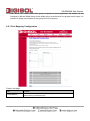
7.1.1 IGMP Proxy Configuration
The IGMP Proxy page allows you to enable multicast on WAN and LAN interfaces. The LAN
interface is always served as downstream IGMP proxy, and you can configure one of the available
WAN interfaces as the upstream IGMP proxy.
Upstream: The interfaces that IGMP requests from hosts are sent to the multicast router.
DG-BG4300N User Manual
Downstream: The interface data from the multicast router are sent to hosts in the multicast group
database.
Fields in this page:
Field
Description
IGMP Proxy
Enable/Disable IGMP proxy feature
Proxy Interface
The upstream WAN interface is selected here.
7.1.2 MLD Configuration
Multicast Listener Discovery (MLD) is a component of the Internet Protocol Version 6 (IPv6) suite. MLD
is used by IPv6 routers for discovering multicast listeners on a directly attached link, much like IGMP is
used in IPv4. The protocol is embedded in ICMPv6 instead of using a separate protocol. MLDv1 is
DG-BG4300N User Manual
similar to IGMPv2 and MLDv2 similar to IGMPv3.
DG-BG4300N User Manual
7.2 UPnP Setup
The DSL device supports a control point for Universal Plug and Play (UPnP) version 1.0, and
supports two key features: NAT Traversal and Device Identification. This feature requires one active
WAN interface. In addition, the host should support this feature. In the presence of multiple WAN
interfaces, select an interface on which the incoming traffic is present.
With NAT Traversal, when an UPnP command is received to open ports in NAT, the application
translates the request into system commands to open the ports in NAT and the firewall. The
interface to open the ports is given to UPnP when it starts up and is part of the configuration of the
application.
For Device Identification, the application will send a description of the DSL device as a control point
back to the host making the request.
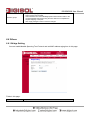
7.2.1 UPnP Configuration
Fields in this page:
Field
Description
UPnP Daemon
Enable/Disable UPnP feature.
Binded WAN Interface
Select WAN interface that will use UPnP from the drop-down lists.
DG-BG4300N User Manual
7.3 SNMP Setup
Simple Network Management Protocol (SNMP) is a troubleshooting and management protocol that
uses the UDP protocol on port 161 to communicate between clients and servers. The DSL device
can be managed locally or remotely by SNMP protocol.
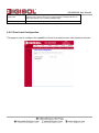
7.3.1 SNMP Protocol Configuration
Fields in this page:
Field
Description
System Description
System description of the DSL device.
System Contact
Contact person and/or contact information for the DSL device.
System Name
An administratively assigned name for the DSL device.
System Location
The physical location of the DSL device.
System Object ID
Vendor objects identifier. The vendor’s authoritative identification of the network
management subsystem contained in the entity.
Trap IP Address
Destination IP address of the SNMP trap.
Community name (readonly)
Name of the read-only community. This read-only community allows read operation
to all objects in the MIB.
DG-BG4300N User Manual
Community name (writeonly)
Name of the write-only community. This write-only community allows write
operation to the objects defines as read-writable in the MIB.
7.4 DNS Setup
7.4.1 DNS Configuration
This page is used to select the way to obtain the IP addresses of the DNS servers.
Fields in this page:
Field
Description
Attain DNS Automatically
Select this item if you want to use the DNS servers obtained by the
WAN interface via the auto-configuration mechanism.
Set DNS Manually
Select this item to configure up to three DNS IP addresses.
DG-BG4300N User Manual
7.4.2 IPv6 DNS
IPv6 configuration is mostly the same as IPv4 configuration (please refer to 6.4.1 DNS Configuration).
IPv4 uses only 32 bits for IP address space, IPv6 allows 128 bits for IP address space.
DG-BG4300N User Manual
7.5 Dynamic DNS
Each time your device connects to the Internet, your ISP assigns a different IP address to your device.
In order for you or other users to access your device from the WAN-side, you need to manually track
the IP that is currently used. The Dynamic DNS feature allows you to register your device with a DNS
server and access your device each time using the same host name. The Dynamic DNS page allows
you to enable/disable the Dynamic DNS feature.
7.5.1 Dynamic DNS ( DDNS) Configuration
On the Dynamic DNS page, configure the following fields:
Field
Description
Enable
Check this item to enable this registration account for the DNS server.
DDNS provider
There are two DDNS providers to be selected in order to register your
device with: DynDNS and TZO. A charge may occur depends on the
service you select.
Hostname
Domain name to be registered with the DDNS server.
DG-BG4300N User Manual
Interface
This field defaults to your device’s WAN interface over which your
device will be accessed.
Username
User-name assigned by the DDNS service provider.
Password
Password assigned by the DDNS service provider.
DG-BG4300N User Manual
8. Firewall Setup
Firewall contains several features that are used to deny or allow traffic from passing through the device.
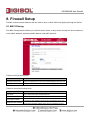
8.1 MAC Filtering
The MAC filtering feature allows you to define rules to allow or deny frames through the device based on
source MAC address, destination MAC address, and traffic direction.
Fields on the first setting block:
Field
Description
Outgoing Default Action
Specify the default action on the LAN to WAN bridging/forwarding path.
Incoming Default Action
Specify the default action on the WAN to LAN bridging/forwarding path.
Fields on the second setting block:
Field
Description
Rule Action
Deny or allow traffic when matching this rule.
Direction
Traffic bridging/forwarding direction.
The source MAC address. It must be xxxxxxxxxxxx format. Blanks can
be used in the MAC address space and are considered as don’t care.
The destination MAC address. It must be xxxxxxxxxxxx format. Blanks
Destination MAC Address
can be used in the MAC address space and are considered as don’t
Source MAC Address
DG-BG4300N User Manual
care.
8.2 IP/Port Filtering Setup
8.2.1 IP/Port Filtering
The IP/Port filtering feature allows you to deny/allow specific services or applications in the forwarding
path.
Fields on the first setting block:
Field
Description
Outgoing Default Action
Specify the default action on the LAN to WAN forwarding path.
Incoming Default Action
Specify the default action on the WAN to LAN forwarding path.
Fields on the second setting block:
Field
Description
Rule Action
Deny or allow traffic when matching this rule.
Direction
Traffic forwarding direction.
Protocol
There are 3 options available: TCP, UDP and ICMP.
Source IP Address
The source IP address assigned to the traffic on which filtering is
applied.
Source Subnet Mask
Subnet-mask of the source IP.
Source Port
Starting and ending source port numbers.
Destination IP Address
The destination IP address assigned to the traffic on which filtering is
applied.
DG-BG4300N User Manual
Destination Subnet Mask Subnet-mask of the destination IP.
Destination Port
Starting and ending destination port numbers.
DG-BG4300N User Manual
8.2.2 IPv6/ Port Filtering
IPv6 configuration is mostly the same as IPv4 configuration (please refer to 8.2.1IP/Port Filtering). IPv4
uses only 32 bits for IP address space. IPv6 allows 128 bits for IP address space.
DG-BG4300N User Manual
8.3 URL Filter
The URL Blocking is the web filtering solution. The firewall has the ability to block access to specific web
URLs based on string matches. This can allow large numbers of URLs to be blocked by specifying only a
FQDN (such as tw.yahoo.com). The URL Blocking enforces a Web usage policy to control content
downloaded from, and uploaded to the Web.
8.3.1 URL Blocking Configuration
Fields in this page:
Field
Description
URL Blocking capability
Check this item to enable the URL Blocking feature.
Keyword
The filtered keyword such as yahoo. If the URL includes this keyword,
the yahoo URL’s will be blocked to access.
DG-BG4300N User Manual
8.4 ACL Setup
The Access Control List (ACL) is a list of permissions for a packet to be matched. The list specifies who
is allowed to access this device. If ACL is enabled, all hosts cannot access this device except for the
hosts with IP address in the ACL table.
8.4.1 ACL Configuration
1.
LAN – You can enable LAN ACS Switch to allow/block the PC to access the Modem.
2.
WAN – You can enable web(http)/telenet/ftp/tftp/snmp/ping for WAN access.
DG-BG4300N User Manual
8.4.2 IPv6 ACL Configuration
IPv6 configuration is mostly the same as IPv4 configuration (please refer to 7.4.1 ACL Configuration).
IPv4 uses only 32 bits for IP address space; IPv6 allows 128 bits for IP address space.
DG-BG4300N User Manual
8.5 DoS Setting
A denial-of-service attack (DoS attack) is an attempt to make a computer resource unavailable to its
intended users. One common method of attack involves saturating the target machine with external
communications requests, such that it cannot respond to legitimate traffic, or responds so slowly as to be
rendered effectively unavailable. Such attacks usually lead to a server overload. In general terms, DoS
attacks are implemented by either forcing the targeted computer(s) to reset, or consuming its resources
so that it can no longer provide its intended service or obstructing the communication media between the
intended users and the victim so that they can no longer communicate adequately.
Enable DoS Prevention to detect and prevent denial of service attacks through automatic rate filtering or
rules to protect legitimate users during the DoS attacks.
DG-BG4300N User Manual
9. Maintenance Setup
9.1 Upgrade
9.1.1 Upgrade Firmware
To upgrade the firmware on the DSL device:
Click the Browse button to select the firmware file.
Confirm your selection.
Click the Upload button to start upgrading.
IMPORTANT!
Do not turn off your DSL device or press the Reset button while this procedure is in
progress.
DG-BG4300N User Manual
9.1.2 Backup/Restore Settings
This page allows you to backup and restore your configuration into and from file on your host PC.
DG-BG4300N User Manual
DG-BG4300N User Manual
9.2 Password
The first time you log into the system, you use the default password. There are two-level for login: admin
and user. The admin and user password configuration allows you to change the password for
administrator and user.
9.2.1 User Account Configuration
Fields in this page:
Field
Description
User Name
Selection of user levels are: admin and user.
Old Password
Enter the old password for this selected login.
New Password
Enter the new password here.
Confirmed Password
Enter the new password here again to confirm.
Privilege
Selection of privilege levels are: root or user.
DG-BG4300N User Manual
9.3 Reboot
Restart the ADSL router.
9.3.1 Commit/Reboot
Function buttons in this page:
1. Save Current Configuration >> Save changes.
2. Factory Default Configuration >> Restore router to factory default settings.
3. Commit Changes >> Save the changes into flash memory.
4. Reset >> Clear the changes from the setting.
5. Reboot >> Restart the modem.
DG-BG4300N User Manual
9.4 Time Setup
Select a Network Time Server for synchronization. You can type in the address of a time server. If you
have trouble using one server, enter another. Or, you can set the time manually.
9.4.1 System Time Configuration
Fields in this page:
Field
Description
System Time
The current time of the specified time zone. You can set the current time by
yourself or configured by SNTP.
Time Zone Select
The time zone in which the DSL device resides.
State
Enable the SNTP client to update the system clock.
Server
The IP address or the host name of the SNTP server. You can select from the list
or set it manually.
NTP Start
Start to check the GMT time
DG-BG4300N User Manual
9.5 Log Setup
You can setup the system log file.
9.5.1 Log Setting
This page shows the system log.
DG-BG4300N User Manual
9.6 Diagnostic Setup
The DSL device supports some useful diagnostic tools.
9.6.1 Ping Diagnostic
Ping operates by sending Internet Control Message Protocol (ICMP) echo request packets to the target
host and waiting for an ICMP response. In the process it measures the time from transmission to
reception (round-trip time) and records any packet loss.
9.6.2 Ping6 Diagnostic
IPv6 configuration is mostly the same as IPv4 configuration (please refer to 9.6.1 Ping Diagnostic). IPv4
uses only 32 bits for IP address space; IPv6 allows 128 bits for IP address space.
DG-BG4300N User Manual
9.6.3 Traceroute Diagnostic
Traceroute is a computer network diagnostic tool for displaying the route (path) and measuring transit
delays of packets across an Internet Protocol (IP) network.
9.6.4 OAM Fault Management – Connectivity Verification
In order to isolate the ATM interface problems, you can use ATM OAM loopback cells to verify
connectivity between VP/VC endpoints, as well as segment endpoints within the VP/VC.
OAM F4 cells operate at the VP level. They use the same VPI as the user cells, however, they use two
different reserved VCIs, as follows:
VCI=3 Segment OAM F4 cells.
VCI=4 End-to-End OAM F4 cells.
OAM F5 cells operate at the VC level. They use the same VPI and VCI as the user cells. To distinguish
between data and OAM cells, the PTI field is used as follows:
PTI=100 Segment OAM F5 cells processed by the next segment.
DG-BG4300N User Manual
PTI=101 End-to-End OAM F5 cells which are only processed by end stations terminating an ATM link.
9.6.5 ADSL Diagnostic
This page shows the ADSL diagnostic result. Click “Start” button to start the ADSL diagnostic.
DG-BG4300N User Manual
9.6.6 Diagnostic Test
The Diagnostic Test page shows the test results for the connectivity of the physical layer and protocol
layer for both LAN and WAN sides.
Fields in this page:
Field
Description
Select the Internet
Connection
The available WAN side interfaces are listed. You have to select one for the WAN
interface configured and run the Diagnostic test.
DG-BG4300N User Manual
Troubleshooting
If you find that the router is not working properly or stops responding don’t panic! Before you contact your
dealer of purchase for help, please read this troubleshooting first.
Scenario
Unable
Solution
to
access
the a. Please check the power cord connection and network cable of
router through web page
this router. All cords and cables should be correctly and firmly
inserted into the router.
b. If all LED’s on the router are off, please check the status of A/C
power adapter, and make sure it’s correctly powered.
c. You must use the same IP address subnet as the router uses.
d. Are you using MAC or IP address filter? Try to connect the router
by another computer and see if it works; if not, please restore
your router to factory default settings (pressing ‘reset’ button for
over 10 seconds).
e. Set your computer to obtain an IP address automatically (DHCP),
and see if your computer can get an IP address.
f.
If you did a firmware upgrade and this happens, contact your
dealer of purchase for help.
g. If all above solutions don’t work, contact the dealer of purchase
for help.
h. Clear your Internet browser history and cache memory.
Can’t get connected to a. Go to ‘Status’ -> ‘Internet Connection’ menu, and check Internet
Internet
connection status.
b. Please be patient, sometimes Internet is just that slow.
c. Bypass the router and verify whether you can get connected to
internet as before.
d. Check PPPoE user ID and password again.
e. Call your Internet service provider and check if there’s something
wrong with their service.
f.
If you just can’t connect to one or more websites, but you can still
use other internet services, please check URL/Keyword filter.
g. Try to reset the router and try again.
h. Verify the line with device provided by your Internet service
DG-BG4300N User Manual
provider too.
i.
Try to use IP address instead of hostname. If you can use IP
address to communicate with a remote server, but can’t use
hostname, please check DNS settings.
I can’t locate my router by a. ‘Broadcast ESSID’ set to off?
my wireless client
b. Both the antennas are secure.
c. Are you too far from your router? Try to get closer.
d. Please remember that you have to input ESSID on your wireless
client manually, if ESSID broadcast is disabled.
File download is very slow a. Are you using QoS function? Try to disable it and try again.
or breaks frequently
b. Internet is slow sometimes, be patient.
c. Try to reset the router and see if the download speed improves.
d. Try to know what other clients do on your local network. If some
clients are transferring files of big size, other clients will get an
impression that Internet is slow.
e. If this has never happened before, call your Internet service
provider to know if there is something wrong with their network.
I
can’t
log
management
onto
web a. Make sure you’re connecting to the correct IP address of the
interface:
password is wrong
router (Default IP: 192.168.1.1).
b. Password is case-sensitive. Make sure ‘Caps lock’ is not on.
c. If you have forgotten the password, do a hard reset.
Router gets heated up
a. This is not a malfunction as long as you are able to touch the
router’s case.
b. If you smell something wrong or see smoke coming out from the
router or A/C power adapter, please disconnect the router and
A/C power adapter from the utility power (make sure it’s safe
before you’re doing this), and call your dealer of purchase for
help.
The date and time of all a. Adjust the time zone in ‘System > Time Zone’ settings of the
event logs are wrong
router.