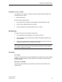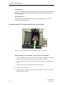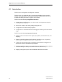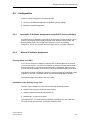
1
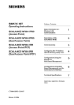
SIMATIC NET Preface, Contents Industrial Ethernet Electrical Lean Switch Introduction 1 Functions 2 Network Topologies 3 Ports and Displays 4 Installation 5 Diagnostics over Industrial Ethernet 6 Technical Specifications 7 Further Support 8 Notes on the CE Mark 9 Glossary 10 Index 11 References 12 Installation Instructions Release 12/2002 A5E00152007 Classification of Safety-Related Notices This document contains notices which you should observe to ensure your own personal safety, as well as to protect the product and connected equipment. These notices are highlighted in the manual by a warning triangle and are marked as follows according to the level of danger: ! Danger indicates that death or severe personal injury will result if proper precautions are not taken. ! Warning indicates that death or severe personal injury can result if proper precautions are not taken. ! Caution with warning triangle indicates that minor personal injury can result if proper precautions are not taken. Caution without warning triangle indicates that damage to property can result if proper precautions are not taken. Notice indicates that an undesirable result or status can occur if the relevant notice is ignored. Note highlights important information on the product, using the product, or part of the documentation that is of particular importance and that will be of benefit to the user. 2 Industrial Ethernet A5E00152007-03 Trademarks SIMATIC, SIMATIC NET and SINEC are registered trademarks of Siemens AG. Third parties using for their own purposes any other names in this document which refer to trademarks might infringe upon the rights of the trademark owners. Safety Instructions Regarding your Product Before you use the product described here, read the safety instructions below thoroughly. Qualified Personnel Only qualified personnel should be allowed to install and work on this equipment . Qualified persons are defined as persons who are authorized to commission, to ground, and to tag circuits, equipment, and systems in accordance with established safety practices and standards. Correct Usage of Hardware Products Please note the following regarding the correct usage of hardware products: Caution This device and its components may only be used for the applications described in the catalog or the technical description, and only in connection with devices or components from other manufacturers which have been approved or recommended by Siemens. This product can only function correctly and safely if it is transported, stored, set up, and installed correctly, and operated and maintained as recommended. Before you use the supplied sample programs or programs you have written yourself, make certain that no injury to persons nor damage to equipment can result in your plant or process. EU Directive: Do not start up until you have established that the machine on which you intend to run this component complies with the directive 89/392/EEC. Industrial Ethernet A5E00152007-03 3 Preface Purpose of the Installation Instructions These installation instructions support you when commissioning in networks with the Electrical Lean Switch (ELS) . Consignment The ELS includes the following components: ● ELS device ● 3-pin plug-in terminal block ● Fittings (brackets, screws) for wall-mounted installation or installation in a 19" cubicle and for the S7-300 standard rail ● "Information on the Product" ● Manual Collection CD Mounting the ELS Follow the instructions in Chapter 5 of these installation instructions. Validity of the Installation Instructions These installation instructions are valid for the following devices: 4 ● ELS TP40 6GK1102-6AA00 ● ELS TP40M 6GK1102-6AB00 ● ELS TP80 6GK1102-7AA00 Industrial Ethernet A5E00152007-03 Preface Further Documentation The "SIMATIC NET Industrial Ethernet Twisted Pair and Fiber-Optic Networks" manual contains information on other SIMATIC NET products that you can operate in conjunction with ELS devices in an Industrial Ethernet network. You can download the electronic version of this network manual from Customer Support on the Internet under entry number 1172207: http://www4.ad.siemens.de/view/cs/de/1172207 Finding Information To help you to find information quickly, the appendix includes the following sections in addition to the table of contents: ● Glossary ● Index Guide to the Manual To help you to find specific information quickly, these installation instructions include the following parts: ● At the front of the installation instructions you will find a complete table of contents. ● The chapters have headings in the left margin with an overview of the contents of the paragraphs in the section. ● Following the appendix, you will find a Glossary in which the most important specialist terms used in the instructions are defined. ● At the back of the installation instructions, you will find an index with which you can find topics quickly. Audience These installation instructions are intended for persons involved in commissioning networks with the ELS. Industrial Ethernet A5E00152007-03 5 Preface Personnel Qualification Requirements Only qualified personnel should be allowed to install and work on this equipment. Qualified personnel as referred to in the installation instructions or in the warning notes are defined as persons who are familiar with the installation, assembly, startup and operation of this product and who possess the relevant qualifications for their work, e.g.: ● Training in or authorization for connecting up, grounding or labeling circuits and devices or systems in accordance with current standards in safety technology; ● Training in or authorization for the maintenance and use of suitable safety equipment in accordance with current standards in safety technology; ● First Aid qualification. Standards and Approvals The ELS TP40, ELS TP40M, and ELS TP80 meet the requirements for the CE mark. For more detailed information about approvals and standards, refer to the appendix. 6 Industrial Ethernet A5E00152007-03 Contents 1 Introduction..................................................................................................................... 9 1.1 ELS TP40 .......................................................................................................... 10 1.2 ELS TP40M ....................................................................................................... 12 1.3 ELS TP80 .......................................................................................................... 14 2 Functions ...................................................................................................................... 15 3 Network Topologies ..................................................................................................... 17 4 5 6 7 3.1 Network Topologies with ELS TP40 .................................................................. 18 3.2 Network Topologies with ELS TP40M............................................................... 19 3.3 Network Topologies with ELS TP80 .................................................................. 20 Ports and Displays ....................................................................................................... 21 4.1 4.1.1 4.1.2 4.1.3 Ports and Displays of the ELS TP40 ................................................................. 22 TP Ports ............................................................................................................. 22 Power Supply..................................................................................................... 24 Displays ............................................................................................................. 26 4.2 4.2.1 4.2.2 4.2.3 Ports and Displays of the ELS TP40M .............................................................. 27 TP Ports ............................................................................................................. 27 Power Supply..................................................................................................... 29 Displays ............................................................................................................. 31 4.3 4.3.1 4.3.2 4.3.3 Ports and Displays of the ELS TP80 ................................................................. 32 TP Ports ............................................................................................................. 32 Power Supply..................................................................................................... 33 Displays ............................................................................................................. 34 Installation and Maintenance ...................................................................................... 35 5.1 Consignment...................................................................................................... 36 5.2 Installation|......................................................................................................... 37 5.3 Maintenance ...................................................................................................... 44 Diagnostics over Industrial Ethernet.......................................................................... 45 6.1 Introduction ........................................................................................................ 46 6.2 6.2.1 6.2.2 Configuration ..................................................................................................... 47 Automatic IP Address Assignment using DHCP (Factory Setting) ................... 47 Manual IP Address Assignment ........................................................................ 47 6.3 6.3.1 6.3.2 6.3.3 6.3.4 Web Based Management (WBM)...................................................................... 57 General .............................................................................................................. 57 Requirements .................................................................................................... 57 Access using WBM............................................................................................ 58 User Interface of the WBM ................................................................................ 59 Industrial Ethernet A5E00152007-03 Preface 7 6.3.5 6.3.6 6.3.7 6.3.8 6.3.9 6.3.10 6.3.11 Management Menus .......................................................................................... 60 Switch Information ............................................................................................. 61 IP Address Information ...................................................................................... 63 E-Mail Configuration .......................................................................................... 65 Trap Configuration ............................................................................................. 67 Event Configuration ........................................................................................... 69 Statistic Information ........................................................................................... 70 6.4 Diagnostics Using SNMP .................................................................................. 71 6.5 6.5.1 6.5.2 Internet Browser Settings .................................................................................. 72 Microsoft Internet Explorer 5.5 or 6.0 ................................................................ 73 Netscape 6.1 or 6.2 ........................................................................................... 78 Technical Specifications ............................................................................................. 80 7.1 Technical Specifications of the ELS TP40 ........................................................ 81 7.2 Technical Specifications of the ELS TP40M ..................................................... 84 7.3 Technical Specifications of the ELS TP80 ........................................................ 87 8 Further Support ............................................................................................................ 89 9 Notes on the CE Mark .................................................................................................. 93 10 Glossary ........................................................................................................................ 95 11 Index 95 12 References .................................................................................................................... 97 8 Industrial Ethernet A5E00152007-03 1 Introduction 1 With the Electrical Lean Switch ELS product generation, you can set up powerful Fast Ethernet networks with a small number of ports in an industrial environment. Nodes can only be attached to the network over twisted-pair ports; in other words, electrical ports. 9 Industrial Ethernet A5E00152007-03 Introduction 1.1 ELS TP40 Possible Attachments ● Two RJ-45 jacks for connecting DTEs ● Two ports with insulation-piercing contacts for the direct attachment of IE FastConnect (FC) cables Figure 1: ELS TP40 10 Industrial Ethernet A5E00152007-03 Introduction Properties of the ELS TP40 Two electrical ports (RJ-45 jacks) 10/100 Mbps (half/full duplex) TP connector technology (RJ-45 jack with MDI-X pinning) Max. cable length 10 m (TP Cord or TP XP Cord) In conjunction with IE FC Outlet RJ-45, a total cable length of a maximum of 100 m is permitted. Two electrical ports 10/100 Mbps (half/full duplex) with insulation-piercing contacts (with MDI-X pinning) Permitted cable types: - IE FC TP standard cable 6XV18402AH10 cable length max. 100 m * - IE FC TP marine cable 6XV18404AH10 cable length max. 85 m * - IE FC TP trailing cable 6XV18403AH10 cable length max. 85 m* *The specified IE FC cable lengths are reduced by 10 m if an IE FC outlet is used. Industrial Ethernet A5E00152007-03 11 Introduction 1.2 ELS TP40M Possible Attachments ● Two RJ-45 jacks for connecting DTEs ● Two ports with insulation-piercing contacts for the direct attachment of IE FastConnect (FC) cables Figure 2: ELS TP40M 12 Industrial Ethernet A5E00152007-03 Introduction Properties of the ELS TP40M Two electrical ports (RJ-45 jacks) 10/100 Mbps (half/full duplex) TP connector technology (RJ-45 jack with MDI-X pinning) Max. cable length 10 m (TP Cord or TP XP Cord) In conjunction with IE FC Outlet RJ-45, a total cable length of a maximum of 100 m is permitted. Two electrical ports 10/100 Mbps (half/full duplex) with insulation-piercing contacts (with MDI-X pinning) Permitted cable types: - IE FC TP standard cable 6XV18402AH10 cable length max. 100 m * - IE FC TP marine cable 6XV18404AH10 cable length max. 85 m * - IE FC TP trailing cable 6XV18403AH10 cable length max. 85 m* *The specified IE FC cable lengths are reduced by 10 m if an IE FC outlet is used. Industrial Ethernet A5E00152007-03 13 Introduction 1.3 ELS TP80 Possible Attachments ● Eight RJ-45 jacks for connecting DTEs Figure 3: ELS TP80 Properties of the ELS TP80 Eight electrical ports (RJ-45 jacks) 10/100 Mbps (half/full duplex) TP connector technology (RJ-45 jack with MDI-X pinning) Max. cable length 10 m (TP Cord or TP XP Cord) In conjunction with IE FC Outlet RJ-45, a total cable length of a maximum of 100 m is permitted. 14 Industrial Ethernet A5E00152007-03 2 Functions 2 This section provides you with an overview of the functions of the Electrical Lean Switch (ELS) product generation. 15 Industrial Ethernet A5E00152007-03 Introduction The Electrical Lean Switches (ELS) allow the cost-effective setup of Ethernet bus or star structures with switching functionality. The ELS switches are intended for use in a switching cubicle. Note If you use an ELS in a redundant OSM/ESM ring, the redundancy function is not supported. Note The requirements of EN61000-4-5, surge test on power supply lines are only met if a Blitzductor VT AD 24V type no. 918 402 is used. Manufacturer: DEHN+SÖHNE GmbH+Co.KG Hans Dehn Str.1 Postfach 1640 D-92306 Neumarkt Germany 16 Industrial Ethernet A5E00152007-03 3 Network Topologies 3 The following network topologies can be implemented with Electrical Lean Switches. 17 Industrial Ethernet A5E00152007-03 Network Topologies 3.1 Network Topologies with ELS TP40 Attachment of individual remotely located DTEs over ELS TP40 to a TP network Figure 4: ELS TP40 Bus Topology Figure 5: ELS TP40 Star Topology 18 Industrial Ethernet A5E00152007-03 Network Topologies 3.2 Network Topologies with ELS TP40M Attachment of individual remotely located DTEs over ELS TP40M to a twisted-pair network Figure 6: ELS TP40M Bus Topology Figure 7: ELS TP40M Star Topology Industrial Ethernet A5E00152007-03 19 Network Topologies 3.3 Network Topologies with ELS TP80 Figure 8: ELS TP80 Star Topology 20 Industrial Ethernet A5E00152007-03 4 Ports and Displays 4 This chapter provides you with an overview of the ports and displays of the ELS. 21 Industrial Ethernet A5E00152007-03 Ports and Displays 4.1 Ports and Displays of the ELS TP40 4.1.1 TP Ports Pinning On the ELS TP40, the TP ports are implemented as RJ-45 jacks and as insulationpiercing contacts with the MDI-X pinning (Medium-Dependent Interface Autocrossover) of a network component. Notice TP Cords or TP-XP Cords with a maximum length of 10 m can be connected to the RJ-45 TP port. In conjunction with IE FC Outlet RJ-45, a total cable length of 100 m is permitted. IE FC TP cable with a maximum length 100 m can be connected to the TP ports with insulation-piercing contacts. Autonegotiation Autonegotiation means the automatic detection of the functionality of the port at the opposite end. Using autonegotiation, repeaters or DTEs can detect the functionality available at the port of a partner device allowing automatic configuration of different types of device. With autonegotiation, two components connected to a link segment can exchange parameters and set themselves to match the supported communication functionality. Note The ELS TP40 is a Plug and Play device that does not require settings to be made when it is installed. MDI /MDIX Autocrossover Function The advantage of the MDI /MDI-X autocrossover function is that straight-pinned cables can be used throughout and crossover cables are unnecessary. This prevents malfunctions resulting from mismatching send and receive wires. This makes installation much easier for the user. The Ethernet Switch chips used in the ELS all support the MDI / MDI-X autocrossover function. 22 Industrial Ethernet A5E00152007-03 Ports and Displays Note Ports of partner stations not supporting autonegotiation must be set to 100 Mbps/ half duplex or 10 Mbps half duplex. Industrial Ethernet A5E00152007-03 23 Ports and Displays 4.1.2 Power Supply The power supply is connected using a 3-pin plug-in terminal block with a screw locking mechanism. L1+ M PE +24V DC Figure 9: ELS TP40 24 Industrial Ethernet A5E00152007-03 Ports and Displays ! Warning Industrial Ethernet ELS TP40 switches are designed for operation with safety extra-low voltage. This means that only safety extra-low voltages (SELV) complying with IEC950/EN60950/ VDE0805 can be connected to the power supply terminals. The power supply unit to supply the ELS TP40 must comply with NEC Class 2 (voltage range 18 - 32 V, current requirement 150 mA). Never connect the ELS to a.c. power supplies or d.c. power supplies greater than 32 V d.c. Power Supply The power supply is connected over a high resistance with the enclosure to allow an ungrounded setup. The ELS TP40 device can also be grounded using the PE screw terminal on the terminal block. Industrial Ethernet A5E00152007-03 25 Ports and Displays 4.1.3 Displays Power display (green LED) The status of the power supply is signaled by a green LED: Status Meaning lit green Power supply L+ is connected Not lit Power supply L+ is not connected or <14 V Port status display (green/yellow LEDs) The status of the ports is signaled by four LEDs: Status 26 Meaning Port 1 to 4 LED lit green TP link exists, no data reception Port 1 to 4 LED lit yellow TP link exists, receiving data at TP port Industrial Ethernet A5E00152007-03 Ports and Displays 4.2 Ports and Displays of the ELS TP40M 4.2.1 TP Ports Pinning On the ELS TP40M, the TP ports are implemented as RJ-45 jacks and as insulation-piercing contacts with the MDI-X pinning (Medium-Dependent Interface Autocrossover) of a network component. Notice TP Cords or TP-XP Cords with a maximum length of 10 m can be connected to the RJ-45 TP port. In conjunction with IE FC Outlet RJ-45, a total cable length of 100 m is permitted. IE FC TP cable with a maximum length 100 m can be connected to the TP ports with insulation-piercing contacts. Autonegotiation Autonegotiation means the automatic detection of the functionality of the port at the opposite end. Using autonegotiation, repeaters or DTEs can detect the functionality available at the port of a partner device allowing automatic configuration of different types of device. With autonegotiation, two components connected to a link segment can exchange parameters and set themselves to match the supported communication functionality. Note The ELS TP40M is a Plug and Play device that does not require settings to be made when it is installed. MDI /MDIX Autocrossover Function The advantage of the MDI /MDI-X autocrossover function is that straight-pinned cables can be used throughout and crossover cables are unnecessary. This prevents malfunctions resulting from mismatching send and receive wires. This makes installation much easier for the user. The Ethernet Switch chips used in the ELS all support the MDI / MDI-X autocrossover function. Industrial Ethernet A5E00152007-03 27 Ports and Displays Note Ports of partner stations not supporting autonegotiation must be set to 100 Mbps/ half duplex or 10 Mbps half duplex. 28 Industrial Ethernet A5E00152007-03 Ports and Displays 4.2.2 Power Supply The power supply is connected using a 3-pin plug-in terminal block with a screw locking mechanism. L1+ M PE +24V DC Figure 10: ELS TP40M Industrial Ethernet A5E00152007-03 29 Ports and Displays ! Warning Industrial Ethernet ELS TP40M switches are designed for operation with safety extra-low voltage. This means that only safety extra-low voltages (SELV) complying with IEC950/EN60950/ VDE0805 can be connected to the power supply terminals. The power supply unit to supply the ELS TP40M must comply with NEC Class 2 (voltage range 18 - 32 V, current requirement 150 mA). Never connect the ELS to a.c. power supplies or d.c. power supplies greater than 32 V d.c. Power Supply The power supply is connected over a high resistance with the enclosure to allow an ungrounded setup. The ELS TP40M device can also be grounded using the PE screw terminal on the terminal block. 30 Industrial Ethernet A5E00152007-03 Ports and Displays 4.2.3 Displays Power Display (green and red LEDs) The status of the ELS TP40M is indicated by a green and a red LED: Status Meaning lit green Power supply L+ is connected not lit Power supply L+ is not connected or <14 V lit or flashing red The red LED should go off after "Power on" after approximately one minute otherwise the ELS TP40M device is defective. Port Status Display (green/yellow LEDs) The status of the ports is signaled by four LEDs: Status Meaning Port 1 to 4 LED lit green TP link exists, no data reception Port 1 to 4 LED lit yellow TP link exists, receiving data at TP port Port Status Display During Startup Following startup, the LEDs are lit in the order shown: ● Red LED (approx. 0.5 s) ● Green power LED (green) and all yellow LEDs for approx. 13 s ● Red/green LEDs flash quickly for approx. 1.5 s The device is operational after a further 3 seconds. Industrial Ethernet A5E00152007-03 31 Ports and Displays 4.3 Ports and Displays of the ELS TP80 4.3.1 TP Ports Pinning On the ELS TP80, the TP ports are implemented as RJ-45 jacks with the MDI-X pinning (Medium-Dependent Interface Autocrossover) of a network component. Notice TP Cords or TP-XP Cords with a maximum length of 10 m can be connected to the RJ-45 TP port. In conjunction with IE FC Outlet RJ-45, a total cable length of 100 m is permitted. Autonegotiation Autonegotiation means the automatic detection of the functionality of the port at the opposite end. Using autonegotiation, repeaters or DTEs can detect the functionality available at the port of a partner device allowing automatic configuration of different types of device. With autonegotiation, two components connected to a link segment can exchange parameters and set themselves to match the supported communication functionality. Note The ELS TP80 is a Plug and Play device that does not require settings to be made when it is installed. MDI /MDIX Autocrossover Function The advantage of the MDI /MDI-X autocrossover function is that straight-pinned cables can be used throughout and crossover cables are unnecessary. This prevents malfunctions resulting from mismatching send and receive wires. This makes installation much easier for the user. The Ethernet Switch chips used in the ELS all support the MDI / MDI-X autocrossover function. Note Ports of partner stations not supporting autonegotiation must be set to 100 Mbps/ half duplex or 10 Mbps half duplex. 32 Industrial Ethernet A5E00152007-03 Ports and Displays 4.3.2 Power Supply The power supply is connected using a 3-pin plug-in terminal block with a screw locking mechanism. Figure 11: ELS TP80 ! Warning Industrial Ethernet ELS TP80 switches are designed for operation with safety extra-low voltage. This means that only safety extra-low voltages (SELV) complying with IEC950/EN60950/ VDE0805 can be connected to the power supply terminals. The power supply unit to supply the ELS TP80 must comply with NEC Class 2 (voltage range 18 - 32 V, current requirement 150 mA). Never connect the ELS to a.c. power supplies or d.c. power supplies greater than 32 V d.c. Power Supply The power supply is connected over a high resistance with the enclosure to allow an ungrounded setup. The ELS TP80 device can also be grounded using the PE screw terminal on the terminal block. Industrial Ethernet A5E00152007-03 33 Ports and Displays 4.3.3 Displays Power display (green LED) The status of the power supply is signaled by a green LED: Status Meaning lit green Power supply L+ is connected Not lit Power supply L+ is not connected or <14 V Port status display (green/yellow LEDs) The status of the ports is signaled by eight LEDs: Status 34 Meaning Port 1 to 8 LED lit green TP link exists, no data reception Port 1 to 8 LED lit yellow TP link exists, receiving data at TP port Port 1 to 8 LED flashes green TP link exists, sending data Industrial Ethernet A5E00152007-03 5 35 Installation and Maintenance 5 Industrial Ethernet A5E00152007-03 Installation and Maintenance 5.1 Consignment Unpacking, Checking the Consignment 1. Check that the consignment includes the following components: – ELS device – Mounting brackets, screws and terminal block – Information on the Product – Manual Collection CD 2. Check each component for any damage. ! 36 Warning Do not install damaged components! Industrial Ethernet A5E00152007-03 Installation and Maintenance 5.2 Installation| There are several ways of installing the ELS: ● Installation on a 35 mm standard rail ● Installation on a SIMATIC S7-300 rail ● Installation in a 19" cabinet (along with other ELS modules in the 19" mounting system) ● Wall mounted Note • Remember that the ELS must only be installed horizontally (ventilation slits top/bottom see Figure 4). To ensure adequate convection, there must be a clearance of at least 5 cm above and below the ventilation slits. You should also make sure that the permitted ambient temperature range is not exceeded. • During installation and operation, make sure that you adhere to the installation instructions and safety-related notices in this description and in the SIMATIC NET Industrial Ethernet Twisted Pair and Fiber-Optic Networks manual /2/. • Unless specifically stated, the following installation options apply to all ELS switches. Preparations Remove the terminal block from the ELS and wire up the power supply lines as described in Section 4.1.2. Industrial Ethernet A5E00152007-03 37 Installation and Maintenance DIN Rail Mounting 1. Install the ELS on a 35 mm standard rail complying with DIN EN 50022. 2. Fit the ELS on to the rail from above and press in the bottom of the device until the catch engages. 3. Connect the electrical cables and the terminal block for the power supply. Figure 12: Installing the ELS on a DIN Standard Rail 38 Industrial Ethernet A5E00152007-03 Installation and Maintenance Removing from a Standard Rail To remove the ELS from the rail, first disconnect the TP cables and pull off the terminal block. Then pull down the device and release it from the rail. Figure 13. Removing from the Standard Rail Industrial Ethernet A5E00152007-03 39 Installation and Maintenance Installation on a SIMATIC S7-300 Standard Rail 1. First secure the supplied brackets to the left and right of the ELS. 2. Fit the guide on the top of the ELS casing into the S7 rail. 3. Screw the ELS to the bottom of the standard rail. Figure 14. Installing an ELS TP40 on a SIMATIC S7-300 Standard Rail 40 Industrial Ethernet A5E00152007-03 Installation and Maintenance Installation in a 19" Cubicle To install in the 19" cubicle, you require the two securing brackets supplied. You can achieve the 19'' width • with 3 ELS devices Follow the steps outlined below: 1. First screw the ELS switches to the supplied mounting plates at the rear. 2. Fit two of the supplied brackets to the sides 3. Secure the devices using the brackets in the 19" cubicle. Wall Mounting To install an ELS on a wall, follow the steps below: 1. Fit the supplied mounting brackets on the sides of the ELS. 2. Secure the device to the wall using the brackets and fittings suitable for the wall in question. 3. Using one of the brackets or the PE screw terminal, connect the device with protective earth with as low a resistance as possible. Note The module must be secured to the wall so that the mounting can carry at least four times the weight of the module. Grounding 19" Cubicle Please note that the ELS must be grounded with low resistance via the two holding brackets. It is also possible to ground the device suing the PE screw terminal on the terminal block. Mounting on a DIN Rail The device is grounded either via the DIN rail or the PE screw terminal on the terminal block. Industrial Ethernet A5E00152007-03 41 Installation and Maintenance Wall Mounting Please note that the ELS must be grounded with low resistance via the two holding brackets. It is also possible to ground the device suing the PE screw terminal on the terminal block. S7 Standard Rail The device is grounded either via the two mounting brackets or the PE screw terminal on the terminal block. Connecting the IE FC TP Cable to the ELS TP40 or ELS TP40M Figure 15. Connecting the IE FC TP Cable to the ELS TP40 or ELS TP40M When connecting the IE FC cables, follow the steps outlined below: 1. Strip the insulation from the FC TP cable with the IE FastConnect stripping tool. (Refer to the instructions for the IE FC stripping tool, Order no. 6GK1901-1GA00) 2. Remove the protective foil from the cores and remove the support element between the cores. 3. Open the cover of the TP ports with insulation piercing contacts. 4. Open the two contact covers. 5. 42 Arrange the wires according to the color code of the contact cover of the TP ports with insulation piercing contacts. Industrial Ethernet A5E00152007-03 Installation and Maintenance 6. Insert the wires of the IE FC TP cable into the contact cover according to the color code. 7. Press down both contact covers to establish contact with the cores. 8. Close and screw down the cover of the TP ports with insulation piercing contacts. If you do not have an IE FastConnect stripping tool to strip the insulation from the IE FastConnect cable, you can prepare the cable to the lengths shown in Figure 8. 42 mm 12 mm Figure 16. Length of Insulation Stripped from the IE FC TP Cable Industrial Ethernet A5E00152007-03 43 Installation and Maintenance 5.3 Maintenance If a fault develops, please send the module to your SIEMENS service department for repair. The devices cannot be repaired on site. 44 Industrial Ethernet A5E00152007-03 6 45 Diagnostics over Industrial Ethernet 6 Industrial Ethernet A5E00152007-03 Diagnostics over Industrial Ethernet 6.1 Introduction The ELS has a configuration and diagnostic interface. The device can be configured and its current status displayed using a graphic interface. All configuration or status data is available as MIB objects and can be modified and displayed within the graphic user interface. The ELS has the following configuration functions: ● Configuration of the IP address, the subnet mask and the gateway using the Primary Setup Tool (PST). ● Reset of all values to the factory settings using the PST. ● Configuration of E-mail and trap recipients. ● Configuration of individual events that will trigger the sending of E-mails and/or traps. The ELS has the following diagnostic functions: ● Display of the current status of the ports (link up/down, transmission rate, and duplicity). ● Display of the MAC address, the IP address, the subnet mask, the gateway, and the type of configuration (manual or using DHCP). ● Trap and E-mail monitoring unit: Cold start events and status changes at the port can be sent to E-mail and/or trap recipients. ● Display of statistical values of errors that have occurred on the network and that were detected by the ELS (CRC, defective frames, collisions etc.). ● Display of the system up time and the hardware and firmware version. 46 Industrial Ethernet A5E00152007-03 Diagnostics over Industrial Ethernet 6.2 Configuration The ELS can be configured in the following ways: ● Automatic IP address assignment using DHCP (factory setting) ● Manual IP address assignment 6.2.1 Automatic IP Address Assignment using DHCP (Factory Setting) If a DHCP server is available in the network environment in which the ELS is to be used, the ELS will be automatically assigned the IP address, subnet mask, and default gateway after it is included in the network. It is then immediately operational. This is only possible when the DHCP server is suitably configured. 6.2.2 Manual IP Address Assignment Primary Setup Tool (PST) If you want to select an IP address, subnet mask, or default gateway for the ELS, you must use the PST. The PST then determines all the accessible Industrial Net Components (INC) in the network and makes them configurable. Using the PST, you can set the IP address, subnet mask, and router (default gateway) of the ELS. If the DHCP mode is activated, the device is reset to the settings it had when it was supplied. In this case, remember that all user-defined settings will be deleted. The following pages describe the use of the PST. Installation of the Primary Setup Tool The PST can be installed on a PC with the following operating systems: ● Windows XP Professional (without service pack) ● Windows 2000 Professional (service pack 2) ● Windows NT 4.0 (service pack 6a) To install the PST, you must have approximately 300 KB free on your hard disk. To communicate over Ethernet, you require a network card. Industrial Ethernet A5E00152007-03 47 Diagnostics over Industrial Ethernet How to install the PST: 1. Start the installation program "pst_install.exe" on the supplied CD. All the necessary files are then copied to the selected folder (the default is the folder: "c:\siemens\pst"). 2. You can now start the application in the installation folder (as default this is the folder: "c:\siemens\pst"). Double-click on the "s7wnpstx.exe" file. 3. When you first start the PST, the dialog shown in Figure 6-1 opens. Here, you can see all the available languages. Select the language you require and confirm the dialog with OK. If the language is displayed in gray, the language package is not available in this PST version. Figure 6-1 Selecting the Language 48 Industrial Ethernet A5E00152007-03 Diagnostics over Industrial Ethernet 4. Once you have selected the language, the menu shown in Figure 6-2 opens. Select a network adapter with Settings -> Network Adapter. All the network interfaces (maximum of four) found in your system will be listed. Select the network adapter you require by clicking on it. Make sure that you read the information in the "readme" file on the supplied CD. Figure 6-2 Configuring the Network Adapter Note If the network adapter installed in your system is not displayed, the DLC protocol required for the network adapter is not installed. In this case, follow the steps outlined below to install the DLC protocol: Windows NT – DLC Protocol Installation ● Select Start -> Settings -> Control Panel. ● Click on the "Network" icon. ● Go to the "Protocols" tab and click the "Add" button. ● From the network protocols displayed, select the DLC Protocol. ● Confirm your selection with "OK". Note Make sure you have your Windows CD at hand. You may need to reinstall Windows service packs. Industrial Ethernet A5E00152007-03 49 Diagnostics over Industrial Ethernet Windows 2000 – DLC Protocol Installation ● Select Start -> Settings -> Control Panel. ● Click on the "Network and Dial-up Connections" icon. ● From the list of network adapters, select the adapter for which you are going to install the DLC protocol by right clicking on the required network adapter and going to "Properties". ● Click on the "Install" button and select "Protocol". ● Click on the "Add" button and select the DLC Protocol from the protocols. ● Confirm your selection with "OK". Note Make sure you have your Windows CD at hand. You may need to reinstall Windows service packs. Windows XP – DLC Protocol Installation For Windows XP, the DLC Protocol must be installed extra since it is not included with the operating system. The supplied CD, however, contains a self-extracting ZIP archive with the name "PST_XP_install.exe" with which you can install the protocol. Start the "PST_XP_install.exe" file by double-clicking on it. Note You will information on the installation procedure in the "win_xp_readme.rtf" file. 50 Industrial Ethernet A5E00152007-03 Diagnostics over Industrial Ethernet User Interface of the PST After starting the PST, the menu shown in Figure 6-3 opens with the various areas. Menu bar Toolbar Component tree Data window Status bar Figure 6-3 SIMATIC NET PST - User Interface ● Menu bar Here you can execute individual actions or specify the configuration of PST. The actions available in the menu bar are also possible in the toolbar. ● Toolbar The toolbar is a convenient way of executing actions by simply clicking on the icons. All the actions available in the toolbar are also available in the menu bar. ● Component tree The component tree lists all the ELS devices available in the network. You can make settings on the individual ELS devices by double-clicking on the corresponding icon in the component tree. ● Data window The data window displays the current values and allows you to enter new settings. Settings that cannot be modified are displayed in gray. ● Status bar The status bar provides you with information about the current status of the PST. Industrial Ethernet A5E00152007-03 51 Diagnostics over Industrial Ethernet Changing the Language Package When you first started the PST, you were asked to select a specific language. You can also change the selected language after this first startup. To change the language, select Settings -> Language. Here you will find a list with all available languages. If the language is displayed in gray, the language package is not available in this PST version. Changing the Network Adapter Configuration If there is more than one network adapter installed in your computer, you can select a specific network adapter. You can do this in the PST menu Settings -> Network Adapter (see Figure 6-4). Here you will find all the network interfaces found on your system (restricted, however, to four). Make sure that you read the information in the "readme" file on the supplied CD. Figure 6-4 Configuring the Network Adapter 52 Industrial Ethernet A5E00152007-03 Diagnostics over Industrial Ethernet Configuring the ELS To configure an ELS, follow the steps outlined below: 1. Select Network -> Browse in the PST menu. The progress bar found in Figure 6-5 is displayed. Figure 6-5 Progress Bar "Browsing Network". You can also start this action directly by clicking the relevant button (magnifying glass) in the toolbar (see Figure 6-6). Figure 6-6 "Browsing Network" Starting Directly Industrial Ethernet A5E00152007-03 53 Diagnostics over Industrial Ethernet 2. The component tree now contains a list of all ELS devices that have been found. Select one of the ELS devices in the component tree by double-clicking on it. The folder of this ELS is opened and a further icon appears. Click on this icon. The data of the interface is displayed in the data window (Figure 6-7). Data not displayed in gray can be modified. MAC Address IP Address Figure 6-7 Component View ● MAC Address Displays the MAC address of the ELS in hexadecimal form. The MAC address cannot be changed. ● Obtain IP address from DHCP server Changes manual configuration of the ELS to automatic configuration using DHCP. Caution: This resets the device to its original settings. All user-defined settings are deleted. ● Assign IP parameters Changes automatic configuration using DHCP to manual configuration of the ELS. 54 Industrial Ethernet A5E00152007-03 Diagnostics over Industrial Ethernet ● IP address IP address of the ELS (maximum range per field: 0 to 255). If you enter an invalid IP address, a warning is displayed and the input is rejected. ● Subnet mask Subnet mask of the ELS (maximum range of numbers per field: 0 to 255). ● Router (default gateway) Enter the IP address of the default gateway if the PC/Internet Browser is not in the same subnet as the ELS. Note Changing the parameters resets and restarts the ELS. This can take up to 15 seconds. 3. Close the folder by clicking on the icon in the menu tree again and download your configuration to the ELS by selecting Module -> Download. A progress bar indicates the status of the download. You can also start this action directly using the appropriate icons in the toolbar (see Figure 6-8). Figure 6-8 Direct Start: "Download Module" Industrial Ethernet A5E00152007-03 55 Diagnostics over Industrial Ethernet 4. Start the Web Based Management (WBM) if you require the full range of functions (including settings). Select Module -> Start INC Browser. You can also start this action directly using the appropriate icons in the toolbar (see Figure 6-9). Figure 6-9 Direct Start: "Starting Web Based Management" Note To load settings on the ELS, you must close the settings window by doubleclicking on the relevant folder in the menu tree. Web Based Management can only be started correctly if your browser includes a Java Virtual Machine (JVM) Version 1.2.2 or higher. For more detailed information, refer to the next section and Section 6.5 of this manual. 56 Industrial Ethernet A5E00152007-03 Diagnostics over Industrial Ethernet 6.3 6.3.1 Web Based Management (WBM) General The ELS includes integrated Web-Based Management; in other words, it can be operated using an Internet browser (such as Microsoft Internet Explorer or Netscape). The modules are operated using a Java applet stored on the ELS that is loaded by the browser. The browser can load the applet only when a Java Virtual Machine (JVM) is present. As of Version 6.x, Netscape provides a JVM integrated in the browser that can be used for Web Based Management. For the Microsoft Internet Explorer, the JVM Plugin must be installed separately. On the CD supplied, you will find a suitable JVM from Sun Microsystems. The latest JVM versions can also be downloaded from the Web pages of Sun Microsystems. For more detailed information, refer to the appendix of this documentation in the Section "Internet Browser Settings". To access the ELS, the IP address must be entered in the address field of the browser. If there is a DNS server in your network that can interpret the address of the ELS, you can also access the module using the logical name. All the information provided by the Java Applet is exchanged with the ELS using SNMP variables. The Management Information Base (MIB) of the ELS is on the supplied CD. 6.3.2 Requirements To access an ELS using WBM, the following requirements must be met: ● Internet Browser You require a PC with an Internet browser. We recommend that you use a Microsoft Internet Explorer Version 5.5 or higher or a Netscape Browser Version 6.1 or higher. Before your Internet browser will work with the ELS, you must make the correct settings in the browser. For more information, refer to Section 6.5 of this manual. ● Firewall If there is a Firewall installed in your network, please make sure that this is configured so that the Java Applet can access the SNMP Port 161. Industrial Ethernet A5E00152007-03 57 Diagnostics over Industrial Ethernet 6.3.3 Access using WBM How to Access WBM on the ELS 1. Open the Internet browser. 2. Enter the IP address or the URL of the ELS in the address field of the Internet Browser as follows: http://<IP address of ELS> for example http://141.73.10.89 and confirm with [RETURN]. 3. A new window opens and the applet is loaded in it (see Figure 6-10). Figure 6-10 "Start" Window If you click the support or SIEMENS icon, you automatically open the relevant A&D home page. 58 Industrial Ethernet A5E00152007-03 Diagnostics over Industrial Ethernet 6.3.4 User Interface of the WBM The dialogs of the ELS are made up of a device status field, a menu tree, and a data window. Device status Menu tree Data window Figure 6-11 SIMATIC NET Network Management User Interface of the ELS ● Device status field The display in the device status field represents the LED display of the ELS. In addition, the transmission rate and duplicity are represented by a separate row of LED symbols. The device status field is displayed and updated in every menu so that you have an overview of the current status of the ELS at all times. The device status field also shows the ELS type (for example ELS-TP40M), the IP address (for example 141.73.10.89) and the location (if "System Location" has been assigned). ● Menu tree By navigating through the menu tree, you can open the individual windows of the ELS WBM in much the same way as when working in the Windows Explorer by clicking the relevant icons. ● Data window The data window displays the current values and allows you to enter new settings. Settings that cannot be modified are displayed in gray. Industrial Ethernet A5E00152007-03 59 Diagnostics over Industrial Ethernet 6.3.5 Management Menus The WBM of the ELS has the following menu structure: Function Explanation Switch Info Hardware Version Software Version System Contact System Location System Name System Up Time IP Address Info MAC Address IP Address Subnet Mask Default Gateway DHCP E-Mail Config E-Mail Address (recipient) "From" (E-mail sender) Subject SMTP Server IP Address Trap Config Trap Address Event Config E-Mail Trap Cold Start Statistics Info Receive Errors Collision Errors Table 6-1 Menu Structure of the ELS Web Based Management The menu commands are described in the following sections. 60 Industrial Ethernet A5E00152007-03 Diagnostics over Industrial Ethernet 6.3.6 Switch Information Clicking the Switch Info menu opens the window shown in Figure 6-12. Figure 6-12 Switch Information Window ● Hardware Version Hardware version of the ELS ● Firmware Version Version of the ELS firmware ● System Contact In this box, you can enter a contact person/address (for example the maintenance engineer) for this device (a maximum of 63 characters). ● System Location In this field, you can enter information about the location of the ELS (a maximum of 63 characters). ● System Name The name of the ELS can be entered in this field (a maximum of 63 characters). Industrial Ethernet A5E00152007-03 61 Diagnostics over Industrial Ethernet ● Get Current Values/Set New Values If you click the "Get Current Values" button, you obtain the values currently stored on the ELS. To transfer the entries in this window to the ELS and to save them there, click on "Set New Values". 62 Industrial Ethernet A5E00152007-03 Diagnostics over Industrial Ethernet 6.3.7 IP Address Information Clicking the IP Address Info menu opens the window shown in Figure 6-13. Figure 6-13 IP Address Information Window ● IP Address IP address of the ELS ● Subnet Mask Subnet mask of the ELS ● Default Gateway Displays the IP address of the default gateway. ● DHCP A check mark in this box indicates whether the address was assigned using DHCP. ● Get Current Values If you click the "Get Current Values" button, you obtain the values currently stored on the ELS. Industrial Ethernet A5E00152007-03 63 Diagnostics over Industrial Ethernet Note The IP address, the subnet mask, and the default gateway of the ELS can be modified using the PST tool. Automatic IP configuration is possible using DHCP. If the IP address of the ELS is changed, the browser link to the ELS is lost. Close the ELS window in the Internet browser and reconnect to the ELS with the new IP address. 64 Industrial Ethernet A5E00152007-03 Diagnostics over Industrial Ethernet 6.3.8 E-Mail Configuration Clicking the E-Mail Config menu opens the window shown in Figure 6-14. Figure 6-14 E-Mail Configuration Window When certain faults occur and are detected by the ELS, it can automatically send an E-mail to a selected E-mail address containing an error message in plain language. Before an E-mail can be sent, it must be configured in this window and be activated in the "Event Configuration Menu". ● E-Mail Address Here, you enter the E-mail address to which an E-mail will be sent if an error occurs (a maximum of 63 characters). ● "From" - Field Address of the sender of the E-mail. Depending on the type and configuration of the SMTP server it may be necessary to configure the sender address (maximum of 63 characters). Industrial Ethernet A5E00152007-03 65 Diagnostics over Industrial Ethernet ● Subject In this field, you can enter a subject for the E-mail (a maximum of 63 characters). ● SMTP Server IP-Address Here, you enter the IP address of the SMTP server via which the E-mail will be sent. Make sure that the ELS can access the SMTP server (maximum range of values per field: 0 to 255). ● Get Current Values/Set New Values If you click the "Get Current Values" button, you obtain the values currently stored on the ELS. To save the entries made in this window, click the Set New Values button. 66 Industrial Ethernet A5E00152007-03 Diagnostics over Industrial Ethernet 6.3.9 Trap Configuration Clicking the Trap Config menu opens the window shown in Figure 6-15. Figure 6-15 Trap Configuration Window If an alarm occurs, the ELS can send traps (alarm messages) to up to two different (network management) stations at the same time. In this menu, you enter the addresses of the stations to which the traps will be sent. The corresponding events must also be activated in the "Event Configuration Menu". ● Trap Address x Enter the IP addresses of the stations to which traps will be sent (range per field: 0 to 255). ● Get Current Values/Set New Values If you click the "Get Current Values" button, you obtain the values currently stored on the ELS. To save the entries made in this window, click the "Set New Values" button. Industrial Ethernet A5E00152007-03 67 Diagnostics over Industrial Ethernet Construction of the Trap report The ELS knows 2 kinds of traps: ● Coldstart ● Change of port status In case of Power On a Coldstart-trap will be sent. If the link-status of a port changes the current contents of the LED-STATUS Register will be sent. LED-Status: Byte 3 Port 4 Byte 2 Port 3 Byte 1 Port 2 Byte 0 Port 1 Port Status: Bit 7 0 Bit 6 0 Bit 5 0 Bit 4 Link Link 1 = Link is up 0 = Link is down Duplex 1 = Link is full duplex 0 = Link is half duplex Speed 1 = Speed is 100Mbps 0 = Speed is 10Mbps Bit 3 0 Bit 2 0 Bit 1 Duplex Bit 0 Speed Example Port 1: Port 2: Port 3: Port 4: Link Up , full duplex, 100 MB Link down Link down Link Up , half duplex, 10 MB Inhalt in LED-Status 10000013hex // 268435475 dez Note Leading Zeros might not be shown by your management system. 68 Industrial Ethernet A5E00152007-03 Diagnostics over Industrial Ethernet 6.3.10 Event Configuration Clicking the Event Config menu opens the window shown in Figure 6-16. Here, you can set link up/down and cold restart events for E-mail and/or trap recipients. Figure 6-16 Event Configuration Window Select, for example, the first box to monitor link up/down events at Port 1 using Email. If there is a change in the port status, an E-mail is sent to the recipient specified in the E-mail configuration menu. ● Get Current Values/Set New Values If you click the "Get Current Values" button, you obtain the values currently stored on the ELS. To save the entries made in this window, click the "Set New Values" button. Industrial Ethernet A5E00152007-03 69 Diagnostics over Industrial Ethernet 6.3.11 Statistic Information Clicking the Statistic Information menu opens the window shown in Figure 6-17. The ELS has internal statistical counters that count the number of bad received frames and collisions for each port. The statistical counters have a numeric range from "0 to 65535". An overflow results if this value is exceeded. Figure 6-17 Statistic Information Window For each port, the ELS can detect errors (CRC, defective frames, etc.) in received frames and count them (receive errors). Collisions occurring on a port are also detected and counted (collision errors). ● Get Current Values If you click the "Get Current Values" button, you obtain the values currently stored on the ELS. 70 Industrial Ethernet A5E00152007-03 Diagnostics over Industrial Ethernet 6.4 Diagnostics Using SNMP With SNMP (Simple Network Management Protocol), a network management station can configure and monitor SNMP-compliant nodes such as the ELS. To make this possible, a management agent is installed in the DTE with which the management station exchanges data using SNMP Get and Set requests. The ELS supports SNMP V1. The data that can be managed are in a database on the DTE (ELS) known as the MIB (Management Information Base) that can be accessed by the management station (or the applet of the ELS Web-Based Management) using the agent. There are standardized MIBs defined in RFCs and private MIBs. Private MIBs are based on RFC 1213 and contain product-specific expansions not included in standard MIBs. The ELS with network management supports MIB II (RFC 1213). ELS private MIB The private MIB of the ELS is on the supplied CD. The private MIB file can also be downloaded from an ELS directly with a Web browser at http://<IP address of the ELS>/snELS.mib. Please note the capitalization of snELS.mib! The description of the MIB objects of the private MIB is included in the MIB and can be read directly with a MIB compiler (for example the network management station) or with a text editor. The read-only community string (SNMP password for read access) is set to public, the read-write community string (SNMP password for read and write access) is set to private. Industrial Ethernet A5E00152007-03 71 Diagnostics over Industrial Ethernet 6.5 Internet Browser Settings To use the WBM of the ELS, you must make the correct settings in the Internet browser. This section contains information about setting the Internet browsers listed in the following table and the Java Virtual Machines used. You can use this procedure as the basis for setting other Internet browser versions. The WBM of the ELS has been tested with these Internet browsers and Java Virtual Machines. Browser Microsoft Internet Explorer 5.5 and 6.0 Netscape 6.1 and 6.2 Java Virtual Machine Plugin Sun Microsystems JRE with Plugin 1.3.0 and 1.3.1 and 1.4.0 Sun Microsystems JRE with Plugin 1.3.0 and 1.3.1 Note The WBM of the ELS has been tested with certain combinations of browsers and Java Virtual Machines (JVM). Only the JVM supplied and installed with the product was tested with Netscape and the JVM from Sun Microsystems was tested with the Internet Explorer. We recommend that you only use one of these combinations. With newer versions, the interaction with the SIMATIC NET devices from the ESM/OSM family cannot be guaranteed. We therefore recommend that you use JVM V1.3.1. JVM V1.3.1 is included on the CD accompanying the product. 72 Industrial Ethernet A5E00152007-03 Diagnostics over Industrial Ethernet 6.5.1 Microsoft Internet Explorer 5.5 or 6.0 1. You can check whether or not you have the update version 5.5 or 6.0 of the Internet Explorer as follows: Open the Internet Explorer and select Help (?) -> About Internet Explorer to open the window shown in Figure 6-18. Figure 6-18 Industrial Ethernet A5E00152007-03 Microsoft Internet Explorer 6.0 – over Internet Explorer Window 73 Diagnostics over Industrial Ethernet 2. Select Tools -> Internet Options -> Advanced, to open the window shown in Figure 6-19. Figure 6-19 Microsoft Internet Explorer 6.0 – Advanced Internet Options 3. Make sure that the option "Use Java 2 v1.x.x for <applet>" is selected under the menu point Java (Sun). You may need to restart the Microsoft Internet Explorer. Note The "Use Java 2 v1.x.x for <applet>" can only be selected if you have already installed the JVM Plugin from Sun Microsystems (download from Sun Microsystems website). 74 Industrial Ethernet A5E00152007-03 Diagnostics over Industrial Ethernet 4. If you use a proxy server that only accepts DNS registered IP addresses and your ELS is not DNS registered, you may need to connect directly to the ELS. To do this, select Tools -> Internet Options -> Connections. The dialog shown in Figure 6-20 opens. Figure 6-20 Industrial Ethernet A5E00152007-03 Microsoft Internet Explorer 6.0 – Connections Window 75 Diagnostics over Industrial Ethernet Select the "LAN Settings" button. The dialog shown in Figure 6-21 opens. Figure 6-21 76 Microsoft Internet Explorer 6.0 – LAN Settings Industrial Ethernet A5E00152007-03 Diagnostics over Industrial Ethernet 5. In this window, disable the proxy server by clicking the "Use a proxy server for your LAN" check box or click the "Advance" button to open the dialog shown in Figure 6-22. Here you can enter the addresses for which the proxy server is not used. Enter the address of the ELS in this window. Using wildcards, you can also enter address ranges. Example: If you enter "141.73.10.*", no proxy server is used for addresses 141.73.10.0 to 141.73.10.255. Figure 6-22 Industrial Ethernet A5E00152007-03 Microsoft Internet Explorer – Proxy Settings 77 Diagnostics over Industrial Ethernet 6.5.2 Netscape 6.1 or 6.2 In Netscape Communicator, select Edit -> Preferences -> Advanced, to open the window shown in Figure 6-23. Figure 6-23 Netscape 6.2 – Advanced Preferences Window 1. Select "Enable Java" and "Enable JavaScript for Navigator". 2. If you use a proxy server that only accepts DNS registered IP addresses and your ELS is not DNS registered, you may need to connect directly to the ELS. 78 Industrial Ethernet A5E00152007-03 Diagnostics over Industrial Ethernet To do this select Edit -> Preferences -> Advanced -> Proxies to open the window shown in Figure 6-24 and set Direct connection to the Internet. Figure 6-24 Industrial Ethernet A5E00152007-03 Netscape 6.2 – Proxy Preferences Window 79 7 80 Technical Specifications 7 Industrial Ethernet A5E00152007-03 Technical Specifications 7.1 Technical Specifications of the ELS TP40 Attachments Attachment of DTEs or Network Components over Twisted Pair 2 x RJ-45 jacks with MDI-X pinning 10/100 Mbps (half/full duplex) Attachment of Industrial Ethernet FC TP cables 2 x insulation piercing contacts with MDI-X 10/100 Mbps (half/full duplex) Connector for power supply 1 x 3-pin plug-in terminal block Electrical Data Power Supply 24 V dc supply (18 to 32 V dc) safety extra-low voltage (SELV) Power loss at DC 24 V 3.6 W Current consumption at rated voltage 150 mA Overcurrent protection at input PTC resettable fuse (0.6 A / 60 V) Permitted Cable Lengths Attachment over Industrial Ethernet FC 100 m standard cable TP cables 85 m trailing cable 85 m marine cable TP Connection When using the FC Outlet RJ-45, the following cable lengths are permitted: 100 m for standard cable 85 m for trailing cable 85 m for marine cable Note The number of ELS switches connected influences the frame propagation time. When a frame passes through the ELS, it is delayed by the Store&Forward function of the switch. - with a frame length of 64 bytes by approximately 10 µs - with a frame length of 1500 bytes by approximately 130 µs This means that the more ELS switches the frame passes through, the longer the propagation time. Aging Time Industrial Ethernet A5E00152007-03 5 minutes 81 Technical Specifications Permitted Ambient Conditions/EMC Operating temperature 0°C to +60°C Storage/transport temperature -40°C to +80°C Relative humidity in operation ‹ 95% (no condensation) Operating altitude 2000 m at max. 56 °C ambient temperature 3000 m at max. 50 °C ambient temperature Noise emission EN 50081-2 Class A Noise immunity EN 50082-2 Degree of protection IP 20 Approvals 82 UL UL 1950 CSA CSA C22.2 No.950 FM FM 3611 C-TICK AS/NZS 2064 (Class A). CE EN 50081-2, EN 50082-2 Shipbuilding approval - Industrial Ethernet A5E00152007-03 Technical Specifications MTBF MTBF 108.85 years Construction Dimensions (W x H x D) in mm 145 x 136.5 x 69 Weight in g 950 Installation options Standard rail S7-300 rail Wall mounted Installation in 19" cubicle Only horizontal installation permitted (ventilation slits top/bottom) Consignment ELS TP40 ● ELS TP40 device ● Mounting brackets, screws and terminal block ● Information on the Product ● Manual Collection CD Order numbers: ELS TP40 6GK1102-6AA00 "Industrial Twisted Pair and Fiber Optic Networks" Manual 6GK1970-1BA10-0AA0 IE FC Stripping Tool 6GK1901-1GA00 IE FC blade cassettes 6GK1901-1GB00 IE FC TP standard cable 6XV1840 2AH10 IE FC TP trailing cable 6XV1840-3AH10 IE FC TP marine cable 6XV1840-4AH10 Industrial Ethernet A5E00152007-03 83 Technical Specifications 7.2 Technical Specifications of the ELS TP40M Attachments Attachment of DTEs or Network Components over Twisted Pair 2 x RJ-45 jacks with MDI-X pinning 10/100 Mbps (half/full duplex) Attachment of Industrial Ethernet FC TP cables 2 x insulation piercing contacts with MDI-X 10/100 Mbps (half/full duplex) Connector for power supply 1 x 3-pin plug-in terminal block Electrical Data Power Supply 24 V dc supply (18 to 32 V dc) safety extra-low voltage (SELV) Power loss at DC 24 V 4.8 W Current consumption at rated voltage 200 mA Overcurrent protection at input PTC resettable fuse (0.6 A / 60 V) Permitted Cable Lengths Attachment over Industrial Ethernet FC 100 m standard cable TP cables 85 m trailing cable 85 m marine cable TP Connection When using the FC Outlet RJ-45, the following cable lengths are permitted: 100 m for standard cable 85 m for trailing cable 85 m for marine cable Note The number of ELS switches connected influences the frame propagation time. When a frame passes through the ELS, it is delayed by the Store&Forward function of the switch. - with a frame length of 64 bytes by approximately 10 µs - with a frame length of 1500 bytes by approximately 130 µs This means that the more ELS switches the frame passes through, the longer the propagation time. 84 Industrial Ethernet A5E00152007-03 Technical Specifications Aging Time 5 minutes Permitted Ambient Conditions/EMC Operating temperature 0°C to +60°C Storage/transport temperature -40°C to +80°C Relative humidity in operation ‹ 95% (no condensation) Operating altitude 2000 m at max. 56 °C ambient temperature 3000 m at max. 50 °C ambient temperature Noise emission EN 50081-2 Class A Noise immunity EN 50082-2 Degree of protection IP 20 Approvals UL UL 1950 CSA CSA C22.2 No.950 FM FM 3611 C-TICK AS/NZS 2064 (Class A). CE EN 50081-2, EN 50082-2 Shipbuilding approval - Industrial Ethernet A5E00152007-03 85 Technical Specifications MTBF MTBF 51 years Construction Dimensions (W x H x D) in mm 145 x 136.5 x 69 Weight in g 950 Installation options Standard rail S7-300 rail Wall mounted Installation in 19" cubicle Only horizontal installation permitted (ventilation slits top/bottom) Consignment ELS TP40M ● ELS TP40 device ● Mounting brackets, screws and terminal block ● Information on the Product ● Manual Collection CD Order numbers: 86 ELS TP40M 6GK1102-6AB00 "Industrial Twisted Pair and Fiber Optic Networks" Manual 6GK1970-1BA10-0AA0 IE FC Stripping Tool 6GK1901-1GA00 IE FC blade cassettes 6GK1901-1GB00 IE FC TP standard cable 6XV1840 2AH10 IE FC TP trailing cable 6XV1840-3AH10 IE FC TP marine cable 6XV1840-4AH10 Industrial Ethernet A5E00152007-03 Technical Specifications 7.3 Technical Specifications of the ELS TP80 Attachments Attachment of DTEs or Network Components over Twisted Pair RJ-45 jacks with MDI-X pinning 10/100 Mbps (half/full duplex) Electrical Data Power Supply 24 V dc supply (18 to 32 V dc) safety extra-low voltage (SELV) Power loss at DC 24 V 3.6 W Current consumption at rated voltage 150 mA Overcurrent protection at input PTC resettable fuse (0.6 A / 60 V) Permitted Cable Lengths TP Connection 0-10 m with TP cord. When using the FC Outlet RJ-45, the following cable lengths are permitted: 100 m for standard cable 85 m for trailing cable 85 m for marine cable Note The number of ELS switches connected influences the frame propagation time. When a frame passes through the ELS, it is delayed by the Store&Forward function of the switch. - with a frame length of 64 bytes by approximately 10 µs - with a frame length of 1500 bytes by approximately 130 µs This means that the more ELS switches the frame passes through, the longer the propagation time. Aging Time Industrial Ethernet A5E00152007-03 5 minutes 87 Technical Specifications Permitted Ambient Conditions/EMC Operating temperature 0°C to +60°C Storage/transport temperature -40°C to +80°C Relative humidity in operation ‹ 95% (no condensation) 2000 m at max. 56°C ambient temperature Operating altitude 3000 m at max. 50°C ambient temperature Noise emission Noise immunity Degree of protection UL CSA FM C-TICK CE Shipbuilding approval MTBF Dimensions (W x H x D) in mm Weight in g Installation options ELS TP80 EN 50081-2 Class A EN 50082-2 IP 20 Approvals UL 1950 CSA C22.2 No.950 FM 3611 AS/NZS 2064 (Class A). EN 50081-2, EN 50082-2 MTBF 81.52 years Construction 145 x 136.5 x 69 950 Standard rail S7-300 rail Wall mounted Installation in 19" cubicle Only horizontal installation permitted (ventilation slits top/bottom) Consignment ● ELS TP80 device ● Mounting brackets, screws and terminal block ● Information on the Product ● Manual Collection CD Order numbers: ELS TP80 6GK1102-7AA00 "Industrial Twisted Pair and Fiber Optic 6GK1970-1BA10-0AA0 Networks" Manual 88 Industrial Ethernet A5E00152007-03 8 Further Support 8 Who to Contact If you have technical questions about using the described product and your problem is not dealt with in the documentation or in the integrated help system, please contact your Siemens representative or dealer. You will find the addresses: ● in our catalog IK PI ● on the Web (http://www.ad.siemens.de/net) 89 Industrial Ethernet A5E00152007-03 Further Support Automation and Drives, Service & Support Service & Support from A&D is available round the clock worldwide. The languages spoken are German and English. French, Italian, and Spanish are also spoken on the authorization hotline. Johnson City Nuremberg Singapore Service & Support Technical Support Authorization Hotline Europe and Africa (Nuremberg) Mo. to Fr. 7:00 to 17:00 (local time, GMT +1) Phone: +49 - (0) 180 - 5050 - 222 Fax: +49 - (0) 180 - 5050 - 223 E-mail: [email protected] Europe and Africa (Nuremberg) Mo. to Fr. 7:00 to 17:00 (local time, GMT +1) Phone: +49 - (0) 911 - 895 - 7200 Fax: +49 - (0) 911 - 895 - 7201 E-mail: [email protected] America (Johnson City) Mo. to Fr. 8:00 to 19:00 (local time, GMT -5) Phone: +1 - (0) 423 - 262 - 2522 Fax: +1 - (0) 423 - 262 - 2231 E-mail: [email protected] Asia and Australia (Singapore) Mo. to Fr. 8:30 to 17:30 (local time, GMT +8) Phone: +65 - (0) 740 - 7000 Fax: +65 - (0) 740 - 7001 E-mail: [email protected] SIMATIC Premium Hotline Worldwide (Nuremberg) Workdays 0:00 to 24:00 (local time, GMT +1) Phone: +49 - (0) 911 - 895 - 7777 Fax: +49 - (0) 911 - 895 - 7001 E-mail: [email protected] 90 Fast callback, (charged, only with SIMATIC Card) Industrial Ethernet A5E00152007-03 Further Support Service & Support on the Internet On the World Wide Web, you will find the very latest information on the entire SIMATIC product range, forexample, answers to frequently asked questions (FAQs), Tips and Tricks, software updates, manuals, and user information. In addition to this free information, you can also order the following, for which a charge is made: ● Software products ● Sample application programs These are charged to the SIMATIC CARD. Internet address: http://www.siemens.de/automation/service&support You can also formulate a question for the SIMATIC Knowledge Manager that will find the solution in the knowledge database. If you are working in an area without an online connection, part of the free information area is available on the "SIMATIC Customer Support Knowledge Base" CD. Industrial Ethernet A5E00152007-03 91 Further Support Training for SIMATIC NET Who to Contact about Training Courses: Siemens AG Trainings-Center für Automatisierungs- und Antriebstechnik A&D PT 49 Kursbüro Östliche Rheinbrückenstraße 50 76181 Karlsruhe Germany Phone: Fax: Internet: +49 - (0) 721 - 595 - 2917 +49 - (0) 721 - 595 - 6087 http://www.sitrain.com Certification The products of SIMATIC NET are manufactured and marketed using a quality management system complying with DIN ISO 9001 and certified by DQS (certificate registration no. 2613). The DQS certificate is recognized in all IQNet countries (Reg. No. 2613). 92 Industrial Ethernet A5E00152007-03 9 9 Notes on the CE Mark Product name: SIMATIC NET SIMATIC NET SIMATIC NET ELS TP40 ELS TP40M ELS TP80 6GK1102-6AA00 6GK1102-6AB00 6GK1102-7AA00 The SIMATIC NET product listed above meets the requirements of the following EU directives: EMC Directive Directive 89/336/EEC “Electromagnetic Compatibility" Area of Application The product is designed for use in an industrial environment: 93 Industrial Ethernet A5E00152007-03 Notes on the CE Mark Area of Application Industry Requirements Noise emission Noise immunity EN 50081-2 : 1993 EN 50082-2 : 1995 Installation Guidelines ● The product meets the requirements if you adhere to the installation and safety instructions contained in this description and in the "SIMATIC NET Industrial Ethernet TP and Fiber-Optic Networks" manual /2/. Conformity Certificates The EU declaration of conformity is available for the responsible authorities according to the above-mentioned EU directive at the following address: Siemens Aktiengesellschaft Bereich Automatisierungs- und Antriebstechnik Industrielle Kommunikation (A&D PT2) Postfach 4848 D-90327 Nürnberg Notes for the Manufacturers of Machines This product is not a machine in the sense of the EU directive on machines. There is therefore no declaration of conformity for the EU directive on machines 89/392/EEC. If the product is part of the equipment of a machine, it must be included in the procedure for obtaining the declaration of conformity by the manufacture of the machine. 94 Industrial Ethernet A5E00152007-03 10 10 Glossary Autonegotiation Procedure standardized by IEEE 802.3 in which the transmission parameters (for example 10/100 Mbps, full/half duplex) are negotiated automatically between the devices. Autosensing See Autonegotiation ELS Electrical Lean Switch ESM Electrical Switch Module EMC Electromagnetic compatibility FC FastConnect MDI-X Medium Dependent Interface Crossover RJ-45 jack with network component pinning. OSM Optical Switch Module TP Port Twisted-pair port 11 Index 95 Industrial Ethernet A5E00152007-03 A Ambient conditions, permitted ..... 81, 84, 86 Authorization hotline................................ 89 C Cable lengths, permitted ............. 81, 84, 86 Consignment ..................... 4, 36, 82, 85, 87 Customer Support ................................... 89 D Displays ................................. 21, 26, 31, 34 E Electrical data .............................. 80, 83, 86 H Hotline ..................................................... 89 I Installation 19" cubicle ........................................... 41 96 standard rail..........................................40 Installation|...............................................37 M Mounting DIN rail .................................................38 wall .......................................................41 N Network topologies ..................................17 P Ports....................................................1, 21 Possible attachments...................10, 12, 14 Power supply ...............................24, 29, 33 T Technical specifications...........................79 Technical Support....................................89 TP ports .......................................22, 27, 32 Industrial Ethernet A5E00152007-03 12 References 12 /1/ SIMATIC NET Industrial Ethernet OSM/ESM Network Management, Release 08/2001 supplied with every device on CD and available at http://www4.ad.siemens.de/view/cs/de/8677203 on the Web. /2/ SIMATIC NET Industrial Twisted Pair and Fiber-Optic Networks, Release 05/2001 Order numbers: 6GK1970-1BA10-0AA0 German 6GK1970-1BA10-0AA1 English 6GK1970-1BA10-0AA2 French 6GK1970-1BA10-0AA4 Italian /3/ SINEC H1 Manual for Triaxial Networks, Release 04 Order number 6GK1970-1AA20-0AA0 (German/English) 97 Industrial Ethernet A5E00152007-03