1
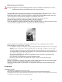
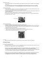
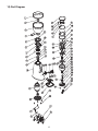
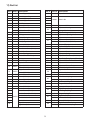
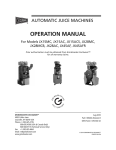
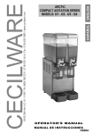
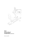
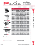
®
Venezia II
™
Model: HC-600
Espresso Grinder
Instruction Manual
Cecilware Corporation
®
NR32A (1/10)
Since 1911
Contents
1) Preface . . . . . . . . . . . . . . . . . . . . . . . . . . . . . . . Pg. 3
2) Technical Specifications . . . . . . . . . . . . . . . . . Pg. 3
3) General Description . . . . . . . . . . . . . . . . . . . . Pg. 3
4) Unpacking and installation . . . . . . . . . . . . . . . Pg. 4
5) Operation . . . . . . . . . . . . . . . . . . . . . . . . . . . . . Pg. 4
6) Safety devices . . . . . . . . . . . . . . . . . . . . . . . . . Pg. 5
7) Safety instructions . . . . . . . . . . . . . . . . . . . . . Pg. 6
8) Maintenance and service . . . . . . . . . . . . . . . . Pg. 6
9) Cleaning . . . . . . . . . . . . . . . . . . . . . . . . . . . . . . Pg. 6
10) Part Diagram . . . . . . . . . . . . . . . . . . . . . . . . . Pg. 8
11) Part List . . . . . . . . . . . . . . . . . . . . . . . . . . . . . Pg. 9
1) Preface
Congratulations for purchasing the HC-600 grinder-doser. The HC-600 is a commercial appliance to be used in
coffee shops, espresso bars, hotels, restaurants, etc. The HC-600 will grind whole been coffee into variable, user
selectable (from super fine to course) coffee powder and will dose it to your espresso machine's Porta-Filter. Read
this manual from cover to cover before using the appliance as it contains important instructions for the safety,
operation, and maintenance of the appliance. Keep the manual in a safe place for future use and reference. The
manufacturer reserves the right to modify the appliance and the manual accordingly.
2) Technical Specifications HC-600:
Dimensions:
Height: "
Width: 8.5"
Length: 13"
Weight: 30 lbs
Stainless Steel Burrs Diameter: 64mm
Hopper capacity: 3 lbs. of beans
Timer: 5 min
Electrical Specifications:
USA 110V/60Hz
Power: 350w @1600RPM
Duty Cycle: 50%
Materials
Metallic: Aluminum alloy cast.
Stainless steel screws and metal-sheet.
Brass alloy cast
Steel Blades
Non metallic: ABS, PC, PP
Bean Hopper Lid
3) General Description
Bean Hopper Door
Bean Hopper
Doser Lid
Hopper Safety Screw
Coffee Outlet Guard
Grinding Dial
Dosing Adjusting Screw
Grinder Body
Dosing Feeding Mechanism
Doser Handle
Coffee Press
Main Switch / Timer
Porta Handle Support
Indication Lamp
Residue Tray
3
4) Unpacking and Installation
!
Warning: All appliances’ technical handling operations such as installation, maintenance, or service
should be performed by certified personnel or by your local dealer.
• After opening the box, make sure that the appliance is intact and that there is no visible damage. If there is
any doubt, DO NOT use the appliance and call your local dealer for further assistance.
• Unpack both boxes carefully. For your convenience we suggest storing all packaging materials where they
can be used in the future, whenever the appliance’s transportation is necessary.
• Place the grinder on a stable flat counter in a dry area away from water or water splashes.
• Position the coffee residue tray underneath the body in front of the appliance.
• Install the bean hopper firmly on top of the body inside the top blade holder.
• Fasten the hopper to the appliance body by means of the supplied screw.(fig. 4.1) Make sure that the screw is
inserted completely through both holes in the hopper and in the top blade holder.
Figure 4.1
• NEVER OPERATE THE GRINDER IF THE BEAN HOPPER IS NOT FULLY SECURED IN ITS POSITION.
• Before plugging in the electrical cord, make sure:
o The appliance voltage and frequency rating (according to the back side label) is the same as the supply
mains.
o The wall socket is fitted with an efficient ground contact. DO NOT plug the appliance into the supply
mains if the ground system was not positively checked to be in compliance with current safety rules. IT
IS COMPULSORY TO GROUND THE APPLIANCE. The manufacturer cannot be held responsible in the
event that this regulation is not complied with.
o The power consumption of the appliance (according to the back side label) is consistent with the
relevant wall socket capacity.
o The wall socket is protected against short-outs and power surges.
o Do not use extension cables, plug adapters for multiple sockets, or makeshift connections.
• Plug in the appliance.
• Upon first time operation, and before placing beans into the hopper, VISUALLY check that the blade rotation
direction is clockwise by switching the appliance ON for a few seconds.
• Should the rotation direction be wrong, do not use the appliance and contact your local dealer for further
instructions.
5) Operation
Switching ON and OFF
• The appliance is equipped with a 5 minute timer.
• Switch ON the appliance by turning the timer knob clockwise to the desired time of operation.
• The appliance will switch OFF automatically when the preset time is over or it can be switched OFF manually
by turning the timer knob all the way counterclockwise.
4
Operating intervals:
• The manufacturer does not recommending using the appliance continuously for a period of time exceeding
30 minutes.
• It is a normal occurrence that during long grinding periods the grinding chamber will heat up. In order to
achieve best grinding results, it is recommended to grind coffee in short intervals of a few minutes each.
Adjusting coffee grind
• The grinding blades’ distance was factory pre-adjusted to satisfy different common coffee grinds from super
fine to coarse) corresponding gap distance from 0.05mm to 0.5mm.
• Turning the grinding dial incrementally counterclockwise will make the grind finer and turning it clockwise will
make the grind coarser.
• Grind a small amount of coffee and test its coarseness with your espresso machine.
• As coffee beans’ qualities and characteristics are changing from time to time it is recommended repeating
this adjustment once in a while.
Safety Screw
Figure 5.1
Adjusting coffee dosing
• The doser is equipped with a portion displacement controlling knob.
• In order to increase the dosed amount the knob should be turned counterclockwise and vice versa (Fig 5.).
• Test the portioned amounts by inserting a porta filter handle (not supplied) all the way into the fork shaped
support and dose one or two portions.
• In order to achieve repeatable and consistent portioned amounts:
o Make sure that the feeding star shaped mechanism is always over filled with coffee.
o Always retract the dosing lever all the way to the end of its stroke.
Figure 5.
Pressing
• Place the porta filter holder against the underside of the pressing device and push it upwards.
6) Safety Devices
A) Thermal Overload Protection
In order to eliminate the risk of fire the motor is equipped with an over-heat protection device which will cut-off
the motor’s power supply should it reach a high temperature.
• In the event that the thermal protection is tripped as a result of malfunction (e.g.: jammed blades, worn out
bearings, foreign object in grinding chamber, etc.) the appliance main switch should be turned off
immediately and the main power plug must be disconnected. For further handling of the device contact your
local service provider, and allow the appliance to cool down before any further maintenance.
• In the event that the thermal protection is tripped as a result of a long continuous operation (read section 5,
for operating intervals) allow the appliance to cool down and reset the thermal cut off protection by
unplugging the main cable from the socket. On the first operation after resetting a tripped over-heat
5
protection device observe the grinding quality and noise level, and if there are any irregularities shut down the
appliance and call a certified technician for a complete analysis of the appliance.
B) Grinding Chamber Safety Screws
The grinding chamber can be a hazardous area if the proper precautions aren’t observed. The hopper safety
screw (fig 4.1) and the grinding dial safety screw (fig 5.1) should never be removed during normal operation of
the appliance unless the appliance is disconnected from the power source.
C) Coffee Outlet Guard
The coffee outlet guard (fig 6.3) must always be fixed to the doser. Never remove the securing screws.
Outlet Guard
Figure 6.3
7) Safety Instructions
• NEVER OPERATE THE GRINDER IF THE BEAN HOPPER IS NOT FULLY SECURED TO THE TOP BLADE
HOLDER. BEFORE REMOVING THE HOPPER FOR ANY REASON MAKE SURE TO DISCONNECT THE
POWER SUPPLY.
• AVOID CLEARING FOREIGN OBJECTS FROM THE GRINDING CHAMBER OR HOPPER WHEN THE
APPLIANCES PLUGGED INTO A POWER SOCKET.
• Never attempt to insert your fingers or any foreign objects into the grinding chamber or blades.
• Be aware that grinding blades continue rotating for a short while after the grinding operation has ended.
• BEFORE ANY MAINTENANCE, EVEN FOR CLEANING, ALWAYS DISCONNECT THE POWER SUPPLY.
• In the event that the appliance has a malfunction or the blades need to be replaced, do not attempt to service
the appliance by yourself.
• Do not change or tamper with the appliance.
• Do not use the appliance barefoot or if your hands or feet are damp.
• Do not use the cable wire to pull and disconnect the power plug.
• Always keep the appliance dry (internally and externally).
• Never put ground coffee into the hopper.
• Never attempt grinding anything else other than coffee beans.
8) Maintenance and Service
!
Warning: All appliances’ technical handling operations, such as installation, maintenance, or
service should be performed by certified personnel or by your local dealer.
Following this rule will ensure long-lasting and reliable performance of your appliance. Check the state of the
grinding blades periodically (approximately every 110 lbs. ground coffee). Good condition blades will result in
a high quality grind and prevent the appliance’s over-heating. Replace grinding blades every 900 lbs. of
ground coffee (with normal hardness blades).
Be aware of the appliance’s noise level. In case the noise level is higher than normal or irregular noises are
coming from within the appliance, get certified personnel to perform an overall check of the appliance.
9) Cleaning
BEFORE ANY CLEANING ROUTINE DISCONNECT THE APPLIANCE POWER SUPPLY. NEVER USE
RUNNING WATER TO CLEAN THE MAIN BODY AND DOSER. USE ONLY PERFECTLY CLEAN CLOTHS OR
BRUSHES TO CLEAN THE APPLIANCE. DO NOT USE ABRASIVE CLEANING PRODUCTS AS THEY MAY
WEAR OUT THE APPLIANCE COATING.
• Cleaning the bean hopper
Take off the bean hopper and rinse it thoroughly with water and soap. Before reinstalling the hopper to the
upper blade holder, make sure it is dried thoroughly.
6
To ensure great coffee taste, clean the bean hopper periodically.
• Cleaning the grinding chamber
Take off the grinding dial (use a screwdriver to take out the dial safety screw). Pull out the upper blade
holder; make sure not to lose the upper blade support springs (3).
Use a brush, a cloth, and a vacuum cleaner to clean the grinding chamber thoroughly. Do not use sharp
objects to scrape coffee residue off of the blades.
Examine both of the blades’ condition and replace them if necessary. The replacement and assembly of a
new set of blades is a delicate task. Only skilled technical personnel should be allowed to perform blade
removal and assembly.
After all cleaning and replacing tasks are through make sure to assemble all of the parts and safety screws
the same way as they were disconnected. If anything does not fit back together or there are left over parts,
do not attempt to operate the appliance, call for the assistance of your technician.
• Cleaning the doser
Discharge all ground coffee; use a clean brush to brush the dosing chambers (by rotating it one by one). Use
a clean cloth to remove stains and hard to remove marks. If a more thorough clean is required, than the
operation must be performed by skilled technician.
10) Part Diagram
8
11) Part list
Dia. # Part # Description
Dia. #
Part #
Description
069
Dispenser Lid
0680
Switch Set
0681
Dispenser Window
068
Dispenser Housing
0683
Sponge Washer
1
0650
Bean Hopper Lid
3
0651
Bean Hopper Ring
38
3
065
Bean Hopper
39
4
0653
Bean Hopper Door
40
5
0654
Dial Plate
41
6
0655
Screw (M4x10)
4
0656
Top Holder
065
Holder Screw (M8x10)
8
0658
Grindstone
44
0684
Adjuster Stopper (M5x10)
9
0659
O Ring
45
0685
Dispenser Adjusting Knob
10
0660
Helical Spring 1mm
46
0686
Wiper
11
0661
Dial Stopper Screw (M4x16)
068
Dispenser Screw (M5x8)
1
066
Dial Spring
0688
Dispenser Screw (M5x1)
13
0655
Screw (M4x10)
48
0689
Tamper (5mm)
14
0663
Bottom Holder
49
0690
Dispenser Top Revolver
15
0664
Dust Cover Screw (M4x8)
50
0691
Dispenser Revolver Cover
16
0665
Shaft Dust Cover
51
069
Dispenser Revolver
1
0666
Motor Bearing
5
0693
Dispenser Spring
18
066
Black /Silver/Red Body
53
0694
Disp. Revolver Screw(M.5x1)
19
0668
Motor
54
0695
Disp.Body Fixing Screw (M5x40)
0
0669
Back Flange
55
0696
Dispenser Bottom Revolver
1
060
Capacitor 1uf
56
069
Dispenser Washer
061
Capacitor Holder
5
0698
Dispenser Bottom Body
Screw (M4x10)
58
0699
Helical Spring 0.5mm
3
06
000
Right Handle Actuator
001
Left Handle Actuator
4
063
Plastic Bottom Cover
00
Dispenser Main Shaft
5
064
Screw (M5x16)
003
Handle Lock Spring
6
065
Screw (M4x10)
004
Tongue Lock Spring
066
Bottom Tray
6
005
Left Handle Tongue
8
06
Esp. Handle Holder
63
006
Tongue Washer
9
064
Screw (M5x16)
64
00
Dispenser Bottom Cover
008
Right Tongue Spring
009
Left Tongue Spring
010
Tongue Spring Pin
011
Right Handle Complete
01
Left Handle Complete
013
Screw (M5x16)
014
Right Handle Main Spring
015
Left Handle Main Spring
31
Cover Screw (M4x18)
3
Switch Cover (On-Off-On)
34
35
36
59
Screw (M5x16)
Knob
068
4
Leg
30
33
43
60
61
65
66
Switch Washer
6
Switch Washer Nut
Main Switch
68
Signal Lamp
69
Signal Lamp Cover
9
Cecilware Corporation
®
Since 1911
43-05 20th. Avenue, LIC NY 11105
Tel: 800.935.2211 / 718.932.1414
Fax: 718.932.7860 • www.cecilware.com
Email: [email protected]