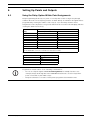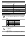
1
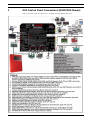
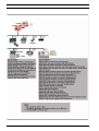
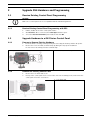
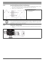
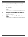
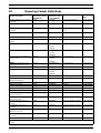
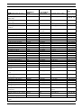
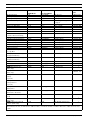
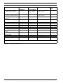
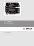
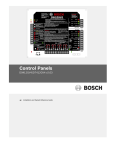
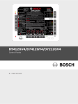
D9412GV4/D7412GV4/D7212GV4
Control Panels
en
Quick Reference Guide
D9412GV4/D7412GV4/D7212GV4
Table of Contents | en
3
Table of Contents
1
GV4 Control Panel Connections (D9412GV4 Shown)
5
2
Upgrade GV4 Hardware and Programming
7
2.1
Receive Existing Control Panel Programming
7
2.1.1
Receive Existing Control Panel Programming with RPS
7
2.2
Upgrade Hardware to a GV4 Series Control Panel
7
2.2.1
Prepare to Remove Existing Hardware
7
2.2.2
Remove the Existing Control Panel
7
2.2.3
Install the GV4 Control Panel In the Enclosure
8
2.2.4
Replace the Terminal Strips
8
2.3
Upgrade Programming to a GV4 Control Panel Programming
9
2.3.1
Upgrade a GV3 Series, GV2 Series, G Series, or Non-G Series Control Panel to a GV4 or Later Using
Remote Programming Software (RPS) 5.14 or Later9
3
Programming the Control Panel
10
3.1
RPS Programming over a Network Using the DX4020 Ethernet Network Interface Module
10
3.2
RPS Programming over a Network Using the ITS-DX4020-G GPRS/GSM Communicator
10
3.3
RPS Programming Using the DX4010V2 RS-232/USB Serial Interface Module
10
3.4
RPS Programming Using the B420 Ethernet Communication Module
10
3.5
Programming Using the Keypad Tools Menu
10
4
Programming to Set Up Central Station Reporting
11
4.1
Basic Telephone Set Up in RPS
11
4.2
Basic Internet Protocol (IP)
11
4.3
Account Number
11
5
Programming the Control Panel for Common Reporting Options
12
5.1
Set Up Daily Test Report Using RPS
12
5.2
Set Up Open and Close Reports Using RPS
12
5.2.1
Area Wide Parameters
12
5.2.2
Set Authority Level
12
6
Setting Up Points and Outputs
13
6.1
Using the Relay Option Within Point Assignments
13
6.2
Point Index (Default Values)
14
7
Add System Users Locally With a Keypad
16
7.1
Add Users (CMD 56) Using a Keypad
16
7.2
Add Card (CMD 56) for Access Control Only Using a Keypad
16
8
Turning the System ON or OFF and Keypad Commands
17
8.1
Arming and Disarming the System
17
8.1.1
Master Arming
17
8.1.2
Disarming
17
Bosch Security Systems, Inc.
Quick Reference Guide
F01U215242 | 01 | 2011.10
4
en | Table of Contents
D9412GV4/D7412GV4/D7212GV4
8.1.3
Set Duress +1 Using RPS
17
8.2
Basic and Advanced Commands
17
8.3
SIA CP-01 False Alarm Prevention Options
18
9
Device Address Settings
19
9.1
D9127 U/T POPIT Dip Switch Key
19
9.2
D9210C Access Control Interface Module Rotary Address Switch Settings
19
9.3
D720, D1255, D1260, D1265 Dip Switch Settings
19
9.4
D9131A Dip Switch Settings
19
9.5
D8129 OctoRelay Dip Switch Settings
19
9.6
D8128C OctoPOPIT Dip Switch Settings
19
9.7
D8128D OctoPOPIT Dip Switch Settings
19
9.8
B208 Octo-input Module Rotary Address Switch Settings
20
9.9
B308 Octo-output Module Rotary Address Switch Settings
20
9.10
B420 Ethernet Communication Module Rotary Address Switch Settings
20
9.11
B520 Auxiliary Power Supply Module Rotary Address Switch Settings
20
9.12
B820 Inovonics Interface Module Rotary Address Switch Settings
20
10
Reporting Format Definitions
21
11
Frequently Asked Questions
28
F01U215242 | 01 | 2011.10
Quick Reference Guide
Bosch Security Systems, Inc.
D9412GV4/D7412GV4/D7212GV4
1
GV4 Control Panel Connections (D9412GV4 Shown) | en
5
GV4 Control Panel Connections (D9412GV4 Shown)
Pages 5 and 6 describe the GV4 Series configuration and supported devices.
Bosch Security Systems, Inc.
Quick Reference Guide
F01U215242 | 01 | 2011.10
6
en | GV4 Control Panel Connections (D9412GV4 Shown)
F01U215242 | 01 | 2011.10
Quick Reference Guide
D9412GV4/D7412GV4/D7212GV4
Bosch Security Systems, Inc.
D9412GV4/D7412GV4/D7212GV4
Upgrade GV4 Hardware and Programming | en
2
Upgrade GV4 Hardware and Programming
2.1
Receive Existing Control Panel Programming
7
NOTICE!
GV4 Series control panels are not compatible with the D5200 Programmer.
2.1.1
Receive Existing Control Panel Programming with RPS
1.
In RPS, double-click on the control panel name.
2.
Click Connect. Once connected, the Panel Sync window opens.
3.
Select the Recieve Panel Data option button and click OK.
2.2
Upgrade Hardware to a GV4 Series Control Panel
2.2.1
Prepare to Remove Existing Hardware
1.
2.
Power down the existing control panel by disconnecting the battery and the AC power.
Remove the four removable terminal strips by tilting the strip up and outward.
Do not remove the wiring from the terminal strip.
1 - Removable terminal strips
2.2.2
Remove the Existing Control Panel
1.
Remove the lock down tab screw.
2.
Lift up on the control panel to free it from the enclosure mounting hooks, and remove the
control panel from the enclosure it.
1 - Lock down tab
Bosch Security Systems, Inc.
Quick Reference Guide
F01U215242 | 01 | 2011.10
8
en | Upgrade GV4 Hardware and Programming
2.2.3
D9412GV4/D7412GV4/D7212GV4
Install the GV4 Control Panel In the Enclosure
1.
Place the GV4 Control Panel in the enclosure using the mounting skirt hook holes on the
back of the control panel and the mounting skirt hooks on the enclosure.
2.
Replace the lock down tab screw.
1 - Mounting skirt hook holes
2 - Mounting skirt hooks
3 - Lock down tab
NOTICE!
If the control panel was previously mounted using the screw hole configuration, the you must
re-mount the new control panel. The GV4 control panel mounting screw hole locations do not
align with the locations for older control panels.
2.2.4
Replace the Terminal Strips
1.
Replace the removable terminal strips by pushing them straight down until they snap into
position.
2.
F01U215242 | 01 | 2011.10
Connect the battery and AC power.
Quick Reference Guide
Bosch Security Systems, Inc.
D9412GV4/D7412GV4/D7212GV4
2.3
Upgrade GV4 Hardware and Programming | en
9
Upgrade Programming to a GV4 Control Panel Programming
NOTICE!
You must upgrade G Series and Non-G Series control panels to GV2 programming prior to
upgrading to GV4 programming.
2.3.1
Upgrade a GV3 Series, GV2 Series, G Series, or Non-G Series Control Panel
to a GV4 or Later Using Remote Programming Software (RPS) 5.14 or Later
RPS version 5.14 or newer is required to upgrade an existing G Series, GV2, or GV3 Series
Control Panel installation to a GV4 Series Control Panel. Refer to the RPS help files for the
specific control panel for additional information on control panel conversion.
1.
In RPS, highlight the control panel name by selecting it.
2.
Click the View button on the Remote Programmer Toolbar.
3.
In the resulting Panel Data - View window, click the Edit button.
4.
In the resulting Panel Data - Edit window, select the new control panel type from the
Panel Type drop-down. (If the control panel is a G or Non-G Series control panel, you
must upgrade to GV2 first, followed by GV3, and then repeat each of these steps to
choose the GV4 control panel).
5.
Click OK to close window.
6.
Click Save in the Panel View window to save the changes and close the Panel View
window.
7.
Click Connect. Once connected, the Panel Sync window opens.
8.
Select the Send ALL RPS Data to Panel option button and click OK.
9.
Once the sync completes, click Disconnect to disconnect from the control panel.
10. Exit RPS.
11. Test the control panel for operation.
Bosch Security Systems, Inc.
Quick Reference Guide
F01U215242 | 01 | 2011.10
10
3
en | Programming the Control Panel
D9412GV4/D7412GV4/D7212GV4
Programming the Control Panel
You can program the control panel with RPS using a network connection or serial connection.
You can program some paramaters of the control panel with keypad programming.
3.1
RPS Programming over a Network Using the DX4020 Ethernet
Network Interface Module
For additional information, refer to IP Address Programming in the Conettix DX4020 Network
Interface Module Installation Guide (P/N: F01U045288).
3.2
RPS Programming over a Network Using the ITS-DX4020-G
GPRS/GSM Communicator
For additional information, refer to the Conettix ITS-DX4020-G Installation Guide (P/
N: F01U163066).
3.3
RPS Programming Using the DX4010V2 RS-232/USB Serial
Interface Module
For additional information, refer to the DX4020 RS-232/USB Serial Interface Module Installation
Instructions (P/N: F01U083036).
3.4
RPS Programming Using the B420 Ethernet Communication
Module
For additional information, refer to Programming Through a Control Panel in the B420 Ethernet
Communication Module Installation and Operation Guide (P/N: F01U215236).
3.5
Programming Using the Keypad Tools Menu
For additional information, refer to the GV4 Series Program Entry Guide (P/N: F01U218312).
F01U215242 | 01 | 2011.10
Quick Reference Guide
Bosch Security Systems, Inc.
D9412GV4/D7412GV4/D7212GV4
4
Programming to Set Up Central Station Reporting | en
11
Programming to Set Up Central Station Reporting
NOTICE!
You can program these items using RPS and the steps listed below. You can also use keypad
programming (refer to the D9412GV4/D7412GV4/D7212GV4 Program Entry Guide (P/
N: F01U218312).
4.1
4.2
Basic Telephone Set Up in RPS
1.
Go to PANEL WIDE PARAMETERS→Phone and Phone Parameters.
2.
Enter the primary telephone number in the Phone 1 field.
3.
If a secondary telephone number is required, enter it in the Phone 2 field.
4.
Go to Panel Wide Parameters→Communicator→Route Group 1.
5.
Enter Phone 1 in the Primary Device field.
6.
If a secondary telephone is required, enter Phone 2 in the Backup Device field.
Basic Internet Protocol (IP)
1.
Go to PANEL WIDE PARAMETERS→Communicator→Route Group 1 Primary Device.
2.
Select SDI Address 88 Path 1.
3.
Go to PANEL WIDE PARAMETERS→SDI RPS/Enhanced Comm→Enable Enhanced
Communications to Yes.
4.
Go to PANEL WIDE PARAMETER→Enhanced Communications.
5.
Select or enter the following values:
NOTICE!
Enhanced Communications settings usually follow the recommendations of the Central
Stations’ staff.
If using an ITS-DX4020-G for communication, refer to the ITS-DX4020-G Installation and
Operation Guide (P/N: F01U163066).
If using an B420 Ethernet Communication Module, refer to the B420 Ethernet Communication
Module Installation and Operation Guide (P/N: F01U215236).
Parameter
Enable Enhanced Communication
Path 1 Network Address
Value
YES
IP or Network address of Central Station
Path 1 Port Number
receiver
Port Number of Central Station receiver
Poll rate recommended by Central Station
Path 1 Poll Rate (seconds)1
Path 1 ACK Wait Time
Path 1 Retry Count
Path 1 Enable Anti-Replay
13 sec (default setting)
5 (default Setting)
Yes (default setting)
1 If the control panel is programmed to send a heartbeat poll to the central station, a rate of 75 sec
maintains the virtual link in most network configurations.
4.3
Account Number
In RPS, go to AREA WIDE PARAMETERS and enter the account number (up to 10 digits) in
the Account Number parameter.
NOTICE!
Area 1 is the only area turned on by default.
Bosch Security Systems, Inc.
Quick Reference Guide
F01U215242 | 01 | 2011.10
12
en | Programming the Control Panel for Common Reporting Options
D9412GV4/D7412GV4/D7212GV4
5
Programming the Control Panel for Common
Reporting Options
5.1
Set Up Daily Test Report Using RPS
1.
Go to SCHEDULES→Skeds.
2.
Enter Function Code 9 (Test Report) in an unused Sked.
3.
Select NO for the Deferred parameter to send test reports regardless of other test
reports sending between scheduled test reports.
4.
Select NO for the Hourly parameter to send test reports only when the sked executes and
not every hour.
5.
6.
Enter the time at which you wish the schedule to send the report.
Leave the Date parameter disabled so that the sked executes by days of the week instead
of only on a selected date.
7.
8.
Select YES for each day of the week.
Select NO for:
–
Except On Holiday
–
Holidays 1 - 4
5.2
Set Up Open and Close Reports Using RPS
5.2.1
Area Wide Parameters
To report each area independently:
–
Go to AREA WIDE PARAMETERS→Area/Bell,Open/Close Options→Acct Open/Close in
RPS. Select NO (default).
–
Go to Area Open/Close in RPS). Select YES (default).
To report by account (Close signal is sent when the last area in an account is armed; Open
signal is sent when the first area is disarmed):
–
Go to AREA WIDE PARAMETERS→Area/Bell,Open/Close Options→Acct Open/Close
in RPS. Select YES.
–
Go to Area Open/Close in RPS. Select NO.
NOTICE!
If you want Perimeter Open and Close, select Perimeter O/C = YES.
5.2.2
Set Authority Level
1.
Go to USER INTERFACE→Authority Levels.
2.
Go to the Authority Level to be used by users sending Open and Close reports.
3.
Select E (enabled) for Area Open/Close.
4.
Select E for Restricted Open/Close.
5.
Select E for Perimeter Open/Close.
F01U215242 | 01 | 2011.10
Quick Reference Guide
Bosch Security Systems, Inc.
D9412GV4/D7412GV4/D7212GV4
Setting Up Points and Outputs | en
6
Setting Up Points and Outputs
6.1
Using the Relay Option Within Point Assignments
13
Relay Programming allows any one point or several points to latch a single relay through
software when the selected point generates an alarm. Relays are number 1 through 8 and are
programmed by entering the number of the relay (1 - 8) in the Relay column in Point
Assignments. This relay latches on a generated alarm and resets after acknowledging and then
clearing the alarm from memory.
D8129 Actual Relay Number
Relay
1
2
3
4
5
6
7
8
D7412GV4/D7212GV41
9
10
11
12
13
14
15
16
D9412GV42
73
74
75
76
77
78
79
80
1 For the D7412GV4 and D7212GV4, connect to Terminal 28 for data (Zonex 1 Out).
2 For the D9412GV4, connect to Terminal 26 for data (Zonex 2 Out).
Table 6.1 Actual Relays Latched by Control Panel Type
Switch Number
1
2
3
4
Setting
ON
OFF
ON
ON
Table 6.2 D8129 Switch Settings for All Control Panel Types
NOTICE!
Programmers must be aware of the following considerations:
–
Do not use relays designated within Point Assignments for multiple functions. For
example, Relays 73 through 80 on the D9412GV4 should not be used for relay-followpoint or area-wide or panel-wide relays.
–
Bosch Security Systems, Inc.
Relays should not be selected to follow points programmed as Invisible Points.
Quick Reference Guide
F01U215242 | 01 | 2011.10
14
en | Setting Up Points and Outputs
6.2
D9412GV4/D7412GV4/D7212GV4
Point Index (Default Values)
Pt Index Description
Pt Index Description
Number
1
2
3
4
5
6
7
8
9
10
11
12
13
14
15
16
24-hr Instant Open/Short
24-hr Inv/Sil on Short
Pull Station
Smoke Detector
Smoke Detector w/Verification
Bell Supervision-D192G
Perimeter: Instant N/O
Perimeter: Delay N/O
Per: Inst N/O Local: Dis
Interior: Instant N/O
Interior: Delay N/O
Int: Inst N/O Local: Dis
Interior: Follower N/O
Maintained Keyswitch
Momentary Keyswitch
Open/Close on Fault
Number
17
18
19
20
21
22
23
24
25
26
27
28
29
30
31
Table 6.3
Point Index Numbers and Descriptions
D279 (Non-Priority)
D279 (Priority)
Easikey Input
Interior: POPIT Motion
Perimeter: POPIT Motion
Fire Supervisory on Open
Non-Fire Supervisory Op
Local: Buzz on Fault
Per: Delay N/On No Troubl
Perimeter: Instant N/C
Perimeter: Delay N/C
Interior: Follower N/C
Interior: Instant N/C
Interior: Delay N/C
CMD7 / CMD9
NOTICE!
The default indexes are not always the best selection.
If you experience unwanted trouble conditions, refer to Table 6.5, Page 15 and make any
necessary adjustments.
Inovonics EchoStream Wireless points produce a Short when faulted and an Open for a
tamper.
To make a custom Point Index, refer to (Table 6.4 and Table 6.5).
Pt Type Description
0
24-Hour
1
Perimeter
2
Interior
3
Interior Follower
4
Keyswitch
Pt Type
6
7
8
9
11
Description
O/C/ Port
D279 (O/C Non-Priority)
D279 (Priority)
Easikey
AUX AC Supervision
Maintained
Keyswitch
5
Momentary
Table 6.4
Point Type Selections
NOTICE!
The selections in Table 6.5 indicate:
–
D = Delayed Response
–
I = Instant Alarm
–
S = Supervisory
–
T = Trouble
–
Blank = No Response
To make a custom point index, use Table 6.4 on Page 14 and Table 6.5 on Page 15. For
example, to create an Interior Follower point with a delay on Open and Trouble on Short, use
Point Type 3 and Point Response 5.
F01U215242 | 01 | 2011.10
Quick Reference Guide
Bosch Security Systems, Inc.
D9412GV4/D7412GV4/D7212GV4
Point Response
Setting Up Points and Outputs | en
0
1
2
3
Selections*
Armed
Open I
I
I
I
Short I
I
I
I
Disarmed Open
T
T
Short
T
T
24-Hour
Open I
T
I
T
Short I
I
T
T
*Selections: D = Delayed Response, I
4
5
6
7
8
D
I
D
I
I
D
I
D
T
D
D
9
A
B
C
D
E
15
F
I
I
I
I
I
T
I
I
I
I
I
I
I
I
T
I
T
T
I
T
I
I
I
T
S
T
S
S
N/A
I
T
T
S
S
S
= Instant Alarm, S = Supervisory, T = Trouble, B = No
Response
Table 6.5 Point Response Selections
Bosch Security Systems, Inc.
Quick Reference Guide
F01U215242 | 01 | 2011.10
16
en | Add System Users Locally With a Keypad
D9412GV4/D7412GV4/D7212GV4
7
Add System Users Locally With a Keypad
7.1
Add Users (CMD 56) Using a Keypad
Step
1
2
3
4
5
6
7
Table 7.1
7.2
Step
1
2
3
4
5
6
7
Table 7.2
Operator Entry
Enter Command 56
Enter passcode and press [ENT].
Enter the user number and press [ENT].
Enter
Enter
Enter the new user’s passcode.
Re-enter the new passcode.
Keypad Response
Enter Passcode
Enter User #
USER # (default name text)
Add Passcode?
Enter New Code
Enter New Again
Code Changed
Adding Users with Command 56
Add Card (CMD 56) for Access Control Only Using a Keypad
Operator Entry
Command 56
Enter passcode and press [ENT]
Enter the user number and press [ENT]
Enter
Next
Enter
Present the credential to the reader.
Keypad Response
Enter Passcode
Enter User #
USER# (default name text)
Change Passcode?
Add Card?
Present Card
Card Added
Adding Cards with Command 56
NOTICE!
To use Add Card (CMD 56), you must program the Assign Door prompt within Command
Center Assignments with the D9210C door controller number. If you do not program the
Assign Door prompt, the keypad reads 9210 NOT READY.
F01U215242 | 01 | 2011.10
Quick Reference Guide
Bosch Security Systems, Inc.
D9412GV4/D7412GV4/D7212GV4
Turning the System ON or OFF and Keypad Commands | en
17
8
Turning the System ON or OFF and Keypad Commands
8.1
Arming and Disarming the System
8.1.1
Master Arming
Enter the passcode and [ENTER] to arm all areas where the user has authority and are areas
within the scope of the keypad.
8.1.2
Disarming
Enter the passcode and [ENTER] to disarm all areas where the user has authority and are
areas within the scope of the keypad.
8.1.3
Set Duress +1 Using RPS
1.
Go to PANEL WIDE PARAMETERS→Miscellaneous→Duress Type. Select 1.
2.
Go to AREA WIDE PARAMETERS→Area Parameters→Duress Enable. Select YES.
3.
Go to User Interface→Authority Levels. In the authority levels to be used, select E for
the Send Duress parameter.
8.2
Basic and Advanced Commands
Basic Commands
CMD 1 (Master Arm) [Master Arms only the
area assigned to the Keypad]
CMD 11 (Master Arm Instant)
CMD 3 (Perimeter Delay)
CMD 4 (Silence Trouble Sounder)
CMD 40 (View memory)
CMD 44 (Walk Test)
CMD 47 (Reset Sensors)
CMD 6 (Watch Mode)
CMD 7 (Special Alert)
CMD 8 (Perimeter Partial)
CMD 9 (Special Alert)
CMD 2 Perimeter Instant
Advanced Commands
CMD 0 (Bypass a Point)
CMD 00 (Unbypass a Point)
CMD 41 (Test Report)
CMD 42 (Status Report)
CMD 43 (Remote Program)
CMD 45 (Change Time/Date)
CMD 49 (Change Display)
CMD 50 (Move to Area)
CMD 51 (Extend Closing)
CMD 52 (Change Sked)
CMD 53 (Delete Passcode)
CMD 54 (Change Relay)
CMD 55 (Change Passcode)
CMD 56 (Add Passcode)
CMD 58 (Fire Test)
PRINT LOG (99 [ENTER])
VIEW LOG (99 [ENTER])
Table 8.1 Basic and Advanced Commands
99 Enter Commands
For each of the following commands, press [9] [9] [ENTER]. Press [NEXT] to view each
command.
–
1 - View Log
–
2 - Print Log
–
3 - Display Revision
–
4 - Service Walk
–
5 - Default Text
Bosch Security Systems, Inc.
Quick Reference Guide
F01U215242 | 01 | 2011.10
18
en | Turning the System ON or OFF and Keypad Commands
–
–
8.3
D9412GV4/D7412GV4/D7212GV4
6 - Tools menu (Requires Service Passcode)
–
Programming
–
Service Bypass
–
RF Points
–
RF Repeaters
–
RF Diagnostics
–
IP Diagnostics
7 - Firmware Updates
SIA CP-01 False Alarm Prevention Options
NOTICE!
Some programming parameters are preset for compliance with SIA standard CP-01 (false
alarm prevention). These settings are in AREA WIDE PARAMETERS→Area Parameters. They
affect control panel operation as described below.
–
Master Arm-No Exit=YES: This setting provides for a Perimeter Delay point to be faulted
when master arming each area, or the arming state defaults to Perimeter Delayed.
–
Exit Delay Warning=YES: When this parameter is set to YES, the alarm bell pulses on and
off every two seconds for the remaining 10 sec of Exit Delay.
–
Entry Delay Warning=YES: When this parameter is set to YES, the alarm bell pulses on
and off every two seconds for the remaining 10 sec of Entry Delay.
F01U215242 | 01 | 2011.10
Quick Reference Guide
Bosch Security Systems, Inc.
D9412GV4/D7412GV4/D7212GV4
Device Address Settings | en
9
Device Address Settings
9.1
D9127 U/T POPIT Dip Switch Key
19
POPIT addresses are binary. Refer to Table 9.1.
Switch Number
Binary Value
0
64
1
32
2
16
3
8
4
4
5
2
6
1
Table 9.1 POPIT Dip Switch Keys
To calculate the switch settings for POPITS, you must determine the value to use in the
calculation. For addresses 9 through 127, subtract 9. For addresses 129 through 247,
subtract 129. Use the following procedure with address 48 as the example, substituting the
actual values in your calculation.
1.
Subtract 9 from 48. The result is 39.
2.
Set the switches that add up to 39 to the OFF positions (32 + 4 + 2 + 1 = 39).
SW 1 OFF = 32
SW 4 OFF = 4
SW 5 OFF = 2
SW 6 OFF = 1
9.2
D9210C Access Control Interface Module Rotary Address
Switch Settings
For additional information, refer to the D9210C Access Control Interface Module Installation and
Operation Guide (P/N: F01U201526).
9.3
D720, D1255, D1260, D1265 Dip Switch Settings
For additional information, refer to:
9.4
–
D720 Series Keypads Installation Instructions (P/N: 7406918000)
–
D1255/D1255B Keypads Installation Instructions (P/N: 7406819000)
–
D1260/D1260B Keypads Installation Guide (P/N: 48101)
–
D1265 Keypads Installation Guide (P/N: F01U169129)
D9131A Dip Switch Settings
For additional information, refer to the Parallel Printer Interface D9131A Installation Guide (P/
N: F01U135506).
9.5
D8129 OctoRelay Dip Switch Settings
For additional information, refer to the D8129 OctoRelay Module Operating and Installation
Guide (P/N: F01U036302).
9.6
D8128C OctoPOPIT Dip Switch Settings
For additional information, refer to the D8128C OctoPOPOIT Module Operating Instructions (P/
N: 7407710000).
9.7
D8128D OctoPOPIT Dip Switch Settings
For additional information, refer to the D8128D OctoPOPOIT Module Installation Guide (P/
N: F01U070537).
Bosch Security Systems, Inc.
Quick Reference Guide
F01U215242 | 01 | 2011.10
20
en | Device Address Settings
9.8
D9412GV4/D7412GV4/D7212GV4
B208 Octo-input Module Rotary Address Switch Settings
For additionl information, refer to the B208 Octo-input Module Installation and Operation Guide
(P/N: F01U215232).
9.9
B308 Octo-output Module Rotary Address Switch Settings
For additional information, refer to the B308 Octo-output Module Installation and Operation
Guide (P/N: F01U215235).
9.10
B420 Ethernet Communication Module Rotary Address Switch
Settings
For additional information, refer to the B420 Ethernet Communication Module Installation and
Operation Guide (P/N: F01U215236).
9.11
B520 Auxiliary Power Supply Module Rotary Address Switch
Settings
For additional information, refer to the B520 Auxiliary Power Supply Module Installation and
Operation Guide (P/N: F01U215240).
9.12
B820 Inovonics Interface Module Rotary Address Switch
Settings
For additional information, refer to the B820 SDI2 Inovonics Interface Module Installation Guide
(P/N: F01U215241).
F01U215242 | 01 | 2011.10
Quick Reference Guide
Bosch Security Systems, Inc.
D9412GV4/D7412GV4/D7212GV4
10
Reporting Format Definitions | en
21
Reporting Format Definitions
Modem IIIa2 Event
Modem IIIa2 Code
Modem IIIa2 Code Contact ID Event
Contact ID
Code
A point supervisory condition
D6500 Mode
Jsppp
Bosch SIA Mode
NriaBSppp
24 hour Non-Burglary
1 150 aa ppp
occurred
A valid local access occurred
RsF01
NLS
Successful Download/
1 412 00 000
NphhhRS
Access
Successful Download/
1 412 00 000
NRS
Access
Successful Download/
1 412 00 000
NAT
NAR
Access
AC Loss
AC Loss
1 301 00 000
3 301 00 000
A valid remote access callback RsssF
occurred
A valid remote access occurred RsssF
AC Fail – mains power supply
AC Restore – mains power
Pssss
Rsss0
supply
Access Denied – Door Secured ADsppp
Nria/idiiiDZppp or Access Denied
1 421 aa uuu
Nria/idiii/
Access Denied – Interlocked
ADsppp
ssxDZppp
Nria/idiiiDWppp or Access Denied
1 421 aa uuu
Nria/idiii/
Access Denied – No rights in
ADsppp
area by card
ssxDWppp
Nria/idiiiDVppp or Access Denied
1 421 aa uuu
Nria/idiii/
(NEW) Access Denied - No
ADsppp
ssxDVppp
Nria/idiiiDVppp
rights in area by passcode
Access Denied – Unknown ID
Access Granted
ADsppp
AGsppp
NriaDDppp
Access Denied
Nria/idiiiDGppp or Access Report by User
Access Denied
1 421 aa uuu
1 421 aa uuu
1 422 aa uuu
Nria/idiii/
Add Card to a User
(NEW) Add Key Fob to User
NsD30
NsD30
ssxDGppp
NidiiiDAuuu
NidiiiDAuuu
Local Only
Local Only
Local Only
Local Only
(Assign Card Event)
Alarm
Alarm Cross Point
Alarm Exit Error
Alarm with Recent Closing
All Points Tested by User
All SDI devices are missing,
Asppp
Asppp
Asppp
Asppp
RsssF
TsssD
NriaBAppp
NriaBMppp
Nria/idiiiEAppp
Nria/CRppp
NRilTC
NpidddET
Burglary
Burglary
Entry/Exit
Entry/Exit
Local Only
Expansion Module Failure
1 130 aa ppp
1 130 aa ppp
1 134 aa ppp
1 459 aa uuu
Local Only
1 333 00 000
power is shorted
All SDI devices are restored,
RsssD
NpidddER
Expansion Module Failure
3 333 00 000
power is normal
An individual SDI device is
TsssD
NpidddEM
Expansion Module Failure
1 333 00 000
missing.
An individual SDI device is
RsssD
NpidddEN
Expansion Module Failure
3 333 00 000
restored.
An invalid remote access
TsssF
NphhhRU
Unsuccessful Access
1 413 00 000
callback occurred
An invalid remote access
TsssF
NRU
Unsuccessful Access
1 413 00 000
occurred
Area Watch End
NsD52
Nria/idiiiiTZ
Local Only
Local Only
1zzz
indicates an SDI, or SDI2 device address value, or network trouble condition. Reference Table 10.2 for more
details.
Bosch Security Systems, Inc.
Quick Reference Guide
F01U215242 | 01 | 2011.10
22
en | Reporting Format Definitions
D9412GV4/D7412GV4/D7212GV4
Modem IIIa2 Code Contact ID Event
Contact ID
D6500 Mode
Area Watch Start
NsD51
Armed perimeter delay
Csiii
Armed perimeter instant
Csiii
Bypass by SDI device
Nsppp
Bypass by Sked
Nsppp
Bypass by User
Nsppp
Bypass Point
Nsppp
Change own password
NsDO4
Change another’s password or NsDO4
Bosch SIA Mode
Nria/idiiiiTW
Nria/idiiiNL
Nria/idiiiNL
Nria/pidddUBppp
Nria/aikkkUBppp
Nria/idiiiUBppp
NriaUBppp
NidiiiiJViiii
NidiiiiJViiii
Code
Local Only
Armed STAY
Armed STAY
Zone/Sensor Bypass
Zone/Sensor Bypass
Zone/Sensor Bypass
Zone/Sensor Bypass
Local Only
Local Only
Local Only
3 441 aa uuu
3 441 aa uuu
1 570 aa ppp
1 570 aa ppp
1 570 aa ppp
1 570 aa ppp
Local Only
Local Only
card
Checksum failure on
TsD15
NYF
RAM Checksum Bad
1 303 00 000
configuration memory
(NEW) Closing by Account
Closing by Area
Closing Early by Area
Closing Late by Area
Communication failure by
Csiii
Csiii
Csiii
Csiii
TsB01
NidiiiCL
Nria/idiiiCL
Nria/idiiiCK
Nria/idiiiCJ
NrggYC
O/C by account
O/C by User
Early O/C
Late O/C
Failure to communicate
3 401 00 uuu
3 401 aa uuu
3 451 aa uuu
3 452 aa uuu
1 354 00 000
route group
Communication failure by
NsB01
NrggYK
event
Failure to communicate
3 354 00 000
1 350 00 1zzz
Modem IIIa2 Event
Modem IIIa2 Code
route group restored
Communication trouble by
TsB01
Nrgg/pidddYS
event
Communication Trouble
network
Communication trouble by
NsB01
Nrgg/pidddYK
CommunicationTrouble
3 350 00 1zzz
network restored
Communication trouble by
TsB01
NphhhYS
Communication Trouble
1 350 00 000
phone
Communication trouble by
NsB01
NphhhYK
Communication Trouble
3 350 00 000
phone restored
Control panel battery low
Tsss9
Control panel battery missing Tsss9
Control panel battery restored Rsss9
NYT
NYM
NYR
Low System Battery
Battery Missing/Dead
Low System Battery
1 302 00 000
1 311 00 000
3 302 00 000
to normal
(NEW) Control Panel Off-line
(NEW) Control Panel On-line
Create Status Report
Date changed – no user
TsssF
RsssF
Sssss
NsD07
Nid5002TS
Nid5002TE
NYY
NJD
System Shutdown
System Shutdown
Status Report to Follow
Time/Date Reset
1 308 00 F02
3 308 00 F02
1 605 00 000
1 625 00 000
identified
Dated changed by user
Delete User by User
(NEW) DNS Failure
NsD07
NsDO5
TsB01
NidiiiJD
NidiiiJXiii
Nrg8/pidddYS
Time/Date Reset
Local Only
Communication Trouble
1 625 00 uuu
Local Only
(NEW) DNS Failure Restore
NsB01
Nrg8/pidddYK
Communication Trouble
Door Closed, Restoral
Door cycled by user
Door Left Open Alarm
Door Left Open Trouble
Door locked by user
Door secured by user
Door unlocked by user
Duress
(NEW) DNS Failure RPS
Rsppp
AGsppp
Asppp
Tsppp
ALsppp
ASsppp
AUsppp
Dsiii
TsB01
NriaDHppp
Nria/idiiiDGppp
NriaDLppp
NriaDMppp
Nria/idiiiDYppp
Nria/idiiiDCppp
Nria/idiiiDOppp
Nria/idiiiHA
Nrg8/pi099YS
1zzz
1 350 00 1zzz
3 350 00 1zzz
Access Door propped open 1 426 aa ppp
Local Only
Local Only
Access Door propped open 1 426 aa ppp
Access Door propped open 1 426 aa ppp
Local Only
Local Only
Local Only
Local Only
Local Only
Local Only
Duress
1 121 aa uuu
Communication Trouble
1 350 00 1zzz
indicates an SDI, or SDI2 device address value, or network trouble condition. Reference Table 10.2 for more
details.
F01U215242 | 01 | 2011.10
Quick Reference Guide
Bosch Security Systems, Inc.
D9412GV4/D7412GV4/D7212GV4
Modem IIIa2 Event
Reporting Format Definitions | en
Modem IIIa2 Code
Modem IIIa2 Code Contact ID Event
Contact ID
Code
23
(NEW) DNS Failure Restore
D6500 Mode
NsB01
Bosch SIA Mode
Nrg8/pi099YK
Communication Trouble
RPS
(NEW) Equipment Fail
TsD29
NIA001
System Peripheral Trouble 1 330 00 1zzz
(SDI2 only)
(NEW) Equipment Restore
RsD29
NIR001
3 350 00 1zzz
(SDI2 only)
Event Log Overflow
AsD01
Event Log Threshold has been TsD01
NJO
NJL
System Peripheral Trouble 3 330 00 1zzz
Restore
Event Log Overflow
1 624 00 000
Event Log 90% Full
1 623 00 000
reached
Extend Close Time by Area
TsD26
Nria/idiii/
Auto-arm Time Extended
1 464 aa uuu
Extra Point
Fail To Close by Area
Fail To Open by Area
Fire Alarm
Fire Cancel
Fire Missing
Fire Restoral from Alarm
Fire Restoral from Trouble
Fire Supervision
Fire Supervision from Restore
Fire Trouble
Fire Walk Test End
Fire Walk Test Start
Force Armed Perimeter Delay
Force Armed Perimeter Instant
Forced Close Early by Area
Forced Close Late by Area
Forced Closing by Area
Forced Point
Invalid local access detected
(NEW) IP Address Error
Tsppp
TsssE
TsssE
Fsppp
\siii
Msppp
Hssppp
Hsppp
Esppp
Esppp
Gssppp
RsssF
TsssF
Csiii
Csiii
Csiii
Csiii
Csiii
Tsppp
TsF01
TsssD
tihhmmCE
NriaXEppp
NriaCI
NriaOI
NriaFAppp
Nria/idiiiFC
NriaFYppp
NriaFHppp
NriaFJppp
NriaFSppp
NriaFVppp
NriaFTppp
Nria/idiiiFK
Nria/idiiiFI
Nria/idiiiNF
Nria/idiiiNF
Nria/idiiiCF
Nria/idiiiCF
Nria/idiiiCF
NriaXWppp
NLU
NET
Maintenance Alert
Failed to Close
Failed to Open
Fire
Cancel
Fire Trouble
Fire
Fire Trouble
Fire Supervisory
Fire Supervisory
Fire Trouble
Fire Test
Fire Test
Partial Arm
Partial Arm
Early O/C
Late O/C
O/C by user
Zone/Sensor Bypass
Unsuccessful access
System Peripheral Trouble
1 393 aa ppp
1 454 aa 000
1 453 aa 000
1 110 aa ppp
1 406 aa uuu
1 373 aa ppp
3 110 aa ppp
3 373 aa ppp
1 200 aa ppp
3 200 aa ppp
1 373 aa ppp
3 604 aa uuu
1 604 aa uuu
3 456 aa uuu
3 456 aa uuu
3 451 aa uuu
3 452 aa uuu
3 401 aa uuu
1 570 aa ppp
1 413 00 000
(NEW) IP Address Error
RsssD
NER
Restore
Low battery on a wireless
Tsppp
NriaXTppp
System Peripheral Trouble 3 330 00 1zzz
Restore
RF Low Battery
1 384 aa ppp
point
Low battery restore on a
Rsppp
NriaXRppp
RF Low Battery
3 384 aa ppp
wireless point
Missing Alarm
Missing Fire Supervision
Missing Supervision
Missing Trouble
(NEW) Network Cable
Msppp
GMsppp
MTsppp
Vsppp
TsssD
NriaUZppp
NriaFZppp
NriaBZppp
NriaUYppp
NET
General Alarm
Fire Trouble
Loss of Supervision - RPM
Loss of Supervision - RPM
System Peripheral Trouble
1 140 aa ppp
1 200 aa ppp
1 382 aa ppp
1 382 aa ppp
Disconnected
(NEW) Network Cable
RsssD
NER
1 330 00 1zzz
1 330 00 1zzz
Connected
Non- Fire Cancel Alarm
\siii
Normal start-up of the control NsD14
Nria/idiiiBC
NRR
System Peripheral Trouble 3 330 00 1zzz
Restore
Cancel
1 406 aa uuu
System Reset
1 305 00 000
panel
(NEW) Opening by Account
NidiiiOP
O/C by account
1zzz
OSiii
1 401 00 uuu
indicates an SDI, or SDI2 device address value, or network trouble condition. Reference Table 10.2 for more
details.
Bosch Security Systems, Inc.
Quick Reference Guide
F01U215242 | 01 | 2011.10
24
en | Reporting Format Definitions
D9412GV4/D7412GV4/D7212GV4
Modem IIIa2 Event
Modem IIIa2 Code
Modem IIIa2 Code Contact ID Event
Contact ID
Bosch SIA Mode
Nria/idiiiOP
Nria/idiiiOK
Nria/idiiiOJ
NYG
Code
Opening by Area
Opening Early by Area
Opening Late by Area
Parameters changed by RPS
D6500 Mode
Osiii
Osiii
Osiii
NsD02
O/C by user
Early O/C
Late O/C
Panel Programming
1 401 aa uuu
1 451 aa uuu
1 452 aa uuu
1 306 00 000
Phone Line Missing 1
Phone Line Missing 2
Phone Line Restored 1
Phone Line Restored 2
Point Bus Fail
Point Bus Restoral, power
TsssB
TsssB
RsssB
RsssB
TsssD
RsssD
NLT1
NLT2
NLR1
NLR2
NET
NER
Changed
Telco 1 Fault
Telco 2 Fault
Telco 1 Fault
Telco 2 Fault
Protection Loop
Protection Loop
1 351 00 000
1 352 00 000
3 351 00 000
3 352 00 000
1 370 00 000
3 370 00 000
normal or bus not missing
RAM Fail with RPS
Relay Reset by Programmer
Relay Reset by Sked
Relay Reset by User
Relay Set by Programmer
Relay Set by Sked
Relay Set by User
Remote Reset – System was
TsF02
NsD22
NsD20
NsD18
NsD21
NsD19
NsD28
NsD11
NRA
NpidddROrrr
NaikkkROrrr
NidiiiROrrr
NpidddRCrrr
NaikkkRCrrr
NidiiiRCrrr
NRN
Unsuccessful access
Sounder/Relay
Sounder/Relay
Sounder/Relay
Sounder/Relay
Sounder/Relay
Sounder/Relay
System Reset
1 413 00 000
3 320 00 000
3 320 00 000
3 320 00 000
1 320 00 000
1 320 00 000
1 320 00 000
1 305 00 000
reset by RPS
(NEW) Replace User’s Key Fob NsD30
NidiiiDAuuu
Local Only
Local Only
(Assign Card Event)
(NEW) Remove User’s Key Fob NsD30
NidiiiDAuuu
Local Only
Local Only
(Assign Card Event)
Restoral
Restoral from Alarm
Restoral from Ground Fault
(NEW) RF Interference
NriaBRppp
NriaBHppp
NriaBRppp
NXQ
Sensor Trouble
Burglary
Ground Fault
RF RCVR Jam
3 380 aa ppp
3 130 aa ppp
3 310 01 000
(SDI2 only)
(NEW) RF Interference Restore RsD08
NXH
RF RCVR Jam Restore
3 344 00 1zzz
(SDI2 only)
(NEW) RF Transmitter Low
TsD10
NidiiiiXT
Battery Test Failure
1 309 00 uuu
RsD10
NidiiiiXR
Battery Test Restore
3 309 00 uuu
(Key Fob)
(NEW) RF Transmitter
Gss001
NriaFTppp
Maintenance Alert
1 393 aa ppp
Maintenance
(NEW) RF Transmitter
Hss001
NriaFRppp
Maintenance Alert
3 393 aa ppp
Maintenance Restoral
ROM Checksum Fail (Not
AsD12
NYX
ROM Checksum bad
1 304 00 000
Used)
(NEW) SDI Device AC Fail
TsssD
NEP
Exp. Module AC Loss
1 342 00 1zzz
(SDI2 only)
(NEW) SDI Device AC Fail
RsssD
NEQ
Exp. Module AC Restore
3 342 00 1zzz
Rsppp
Rsppp
Rsppp
TsD08
1 344 00 1zzz
Battery
(Key Fob)
(NEW) RF Transmitter Low
Battery Restore
Restore (SDI2 only)
1zzz
indicates an SDI, or SDI2 device address value, or network trouble condition. Reference Table 10.2 for more
details.
F01U215242 | 01 | 2011.10
Quick Reference Guide
Bosch Security Systems, Inc.
D9412GV4/D7412GV4/D7212GV4
Reporting Format Definitions | en
25
Modem IIIa2 Code Contact ID Event
Contact ID
D6500 Mode
TsssD
Bosch SIA Mode
NET
Code
Ground Fault
1 310 00 1zzz
RsssD
NER
Ground Fault Restore
3 310 00 1zzz
(SDI2 only)
(NEW) SDI Device Low Battery TsssD
NEB
Exp. Module Low Batt.
1 338 00 1zzz
(SDI2 only)
(NEW) SDI Device Low Battery RsssD
NEV
Exp. Module Low Batt.
3 338 00 1zzz
Restore (SDI2 only)
(NEW) SDI Device Over
TsssD
NYI
Restore
PS Over Current
1 312 00 1zzz
(SDI2 only)
(NEW) SDI Device Over
RsssD
NYJ
PS Over Current Restore
3 312 00 1zzz
Current Restore (SDI2 only)
(NEW) SDI Device Missing
TsssD
NEM
Exp. Module Failure
1 333 00 1zzz
(SDI2 only)
(NEW) SDI Device Missing
TsssD
NEB
Exp. Module Low Batt.
1 338 00 1zzz
Battery (SDI2 only)
(NEW) SDI Device Missing
RsssD
NEV
Exp. Module Low Batt.
3 338 00 1zzz
Battery Restore (SDI2 only)
(NEW) SDI Device Missing
RsssD
NEN
Restore
Exp. Module Failure
3 333 00 1zzz
Restore (SDI2 only)
(NEW) SDI Device Tamper
TsssD
NES
Restore
Exp. Module Tamper
1 341 00 1zzz
(SDI2 only)
(NEW) SDI Device Tamper
TsssD
NES
Exp. Module Tamper
3 341 00 1zzz
Restore (SDI2 only)
(NEW) SDI Device Trouble
TsssD
NET
Restore
System Peripheral Trouble 1 330 00 1zzz
(SDI2 only)
(NEW) SDI Device Trouble
RsssD
NER
Modem IIIa2 Event
(NEW) SDI Bus Fail Ground
Modem IIIa2 Code
Fault
(SDI2 only)
(NEW) SDI Bus Fail Ground
Fault Restore
Current
Restore (SDI2 only)
(NEW) SDI2 Open Trouble
TsssD
NpiidddET
System Peripheral Trouble 3 330 00 1zzz
Restore
Expansion Module Failure 1 333 00 1zzz
(NEW) SDI2 Open Trouble
RsssD
NpidddER
Expansion Module Failure
3 333 00 1zzz
Restoral
Sensor Reset
Service Bypass
Service Bypass Cancel
Service Walk Test End
Service Walk Test Start
Sked Changed – No User
NsD27
Qsppp
Qsppp
RsssF
TsssF
NsD06
Nria/idiiiXIrrr
NriaXKppp
NriaXNppp
NidiiiTE
Nria/idiiiTS
NaikkkJS
Sounder/Relay
Service Request
Service Request
Service On/Off Premises
Service On/Off Premises
Schedule Change
3 320 00 000
1 616 aa ppp
3 616 aa ppp
3 466 aa uuu
1 466 aa uuu
1 630 00 000
Identified
Sked Changed by User
NsD06
Swinger Bypass
Nsppp
Test Report – System Normal, RsssE
Nidiii/aikkkJS
NriaUBppp
NRP & see D6600
Schedule Change
Swinger Bypass
Periodic Test Report
1 630 00 000
1 575 aa ppp
1 602 00 000
Expanded Status
CIM for Status
Test Report – System Normal, RsssE
Items
NRP
Periodic Test Report
1 602 00 000
Non-expanded Status
1zzz
indicates an SDI, or SDI2 device address value, or network trouble condition. Reference Table 10.2 for more
details.
Bosch Security Systems, Inc.
Quick Reference Guide
F01U215242 | 01 | 2011.10
26
en | Reporting Format Definitions
D9412GV4/D7412GV4/D7212GV4
Modem IIIa2 Event
Modem IIIa2 Code
Modem IIIa2 Code Contact ID Event
Contact ID
Bosch SIA Mode
NRY & see D6600
Code
Test Report – System Off-
D6500 Mode
RsssE
Periodic Test – System
CIM for Status
Trouble Present
normal, Expanded Status
1 608 00 000
Test Report – System Off-
RsssE
Items
NRY
Periodic Test – System
1 608 00 000
normal, Non-expanded Status
Time Changed – No User
NsD07
NJT
Trouble Present
Time/Date Reset
1 625 00 000
Identified
Time Changed by Receiver
NsD07
Nid254JT
Time/Date Reset
1 625 00 F01
Sync
Time Changed by User
Trouble
Trouble with Ground Fault
Unverified Event
User Alarm 7
User Alarm 9
User Authority level has
NsD07
Tsppp
Tsppp
Ksppp
Usss7
UUsss9
NsD40
NidiiiJT
NriaBTppp
NriaBTppp
NriaUGppp
Nria/idiiiUA
Nria/idiiiPA
NidiiiJZiii
Time/Date Reset
Sensor Trouble
Ground Fault
Cross-zone Trouble
Personal Emergency
Duress
Local Only
1 625 00 uuu
1 380 aa ppp
1 310 01 000
1 378 aa ppp
1 101 aa uuu
1 121 aa uuu
Local Only
changed
User Passcode Tamper – Too
NsD03
NriaJA
Wrong Code Entry
1 461 aa 000
Many Attempts
Walk Test End
Walk Test Start
Watchdog Reset – SDI Device
RsssF
TsssF
NsD09
Nria/idiiiTE
Nria/idiiiTS
NpidddYW
Walk test mode
Walk test mode
System Reset
3 607 aa uuu
1 607 aa uuu
1 305 00 000
Reported identifies the Source
1zzz
indicates an SDI, or SDI2 device address value, or network trouble condition. Reference Table 10.2 for more
details.
Table 10.1
Reporting Format Definitions
F01U215242 | 01 | 2011.10
Quick Reference Guide
Bosch Security Systems, Inc.
D9412GV4/D7412GV4/D7212GV4
Reporting Format Definitions | en
27
Contact ID data value (zzz) translations
SDI/SDI2 Bus Address
zzz Data Values
Description
1-16
001-016
SDI Keypad 1 through 16
17-19
017-019
SDI Printer 1 through 3
33-40
033-040
Access Module 1 through 8
80
080
SDI Automation Module1
88
088
SDI Network Module 1
92
092
SDI Network Module 2
2-25
201-224
SDI2 Octo-input Modules 1
through 24
66-77
301-312
SDI2 Octo-output Modules 1
through 12
151
801
SDI2 Premise RF Module
161-168
851-858
SDI2 RF Repeater 1 through 8
173
401
SDI2 Network Module 1
174
402
SDI2 Network Module 2
176-183
501-508
SDI2 Power Supply Module 1
through 8
88-91
088-091
Routes 1 through 4 on SDI
Network Module 1
92-95
092-095
Routes 1 through 4 on SDI
Network Module 2
11, 21, 31, 41
411, 421, 431, 441
Routes 1 through 4 on SDI2
Network Module 1
12, 22, 32, 42
412, 422, 432, 442
Routes 1 through 4 on SDI2
Network Module 2
99
499
DNS lookup error of RPS
hostname
Table 10.2
Bosch Security Systems, Inc.
Contact ID data value (zzz) translations table
Quick Reference Guide
F01U215242 | 01 | 2011.10
28
11
en | Frequently Asked Questions
D9412GV4/D7412GV4/D7212GV4
Frequently Asked Questions
What does it mean when my keypad reads "CALL FOR SERVICE"?
That keypad is not receiving data from the control panel.
What does it mean when my keypad reads "SERVICE KEYPAD"?
A supervised keypad has lost communications with the control panel.
How do I arm an area that is not assigned to my keypad?
Add to the FUNCTION LIST a menu item with a function code of 1 and with CC ADDRESS 1-16
set to YES, and a menu item with a function code of 2 and with CC ADDRESS 1-16 set to Yes.
Assign the function codes to the necessary command center. The new menu items allow your
users to select the area they wish to arm or disarm.
How do I perform area-specific functions from a keypad?
Use the MOVE TO AREA command (CMD 50) to move to an area within the keypad’s scope.
Can I default a lockcode without knowing the lockcode?
No. You must send the unit to the Bosch Repair Center.
How do I upgrade the control panel’s firmware version?
When an update is available, you may either:
–
use the optional firmware upgrade key to upgrade the firmware. Lift the control panel
faceplate cover to access the port to insert the upgrade key and read the instructions
located on the back of the faceplate.
OR
–
obtain the firmware update file from Bosch and, using the RPS Firmware Update Wizard,
connect to the panel and send the new version to the control panel (local user
authorization may be required). Always re-test your system when the firmware version
has been changed.
How do I add an access card using the command center?
Use the ADD USER command (CMD 56) to add an access card. Present the access card to the
assigned door to add the card.
What does it mean when my keypad reads "9210 NOT READY"?
No door is assigned to the command center. Check the ASSIGN DOOR parameter within
COMMAND CENTER ASSIGNMENTS menu item, and then enter the D9210C address (1 - 8).
What are SDI addresses 33 to 40?
They are D9210C addresses.
What are SKEDS 41 to 56?
They are Open and Close windows.
How do I test a relay from the keypad?
Use the RELAY CONTROL command (CMD 54) to toggle relays.
How do I toggle the on-board relays A, B, and C?
Use the RELAY CONTROL command (CMD 54), and then the relay number: 253 for A; 254 for
B; and 255 for C.
How many Amp Hours can the panel sustain?
You can connect two (2) 18 Ah batteries for a total of 36 Ah. You can gain up to an additional
27 Ah with by connecting a D8132 module.
F01U215242 | 01 | 2011.10
Quick Reference Guide
Bosch Security Systems, Inc.
D9412GV4/D7412GV4/D7212GV4
Frequently Asked Questions | en
29
Is the control panel compatible with digital or VOIP phone lines?
The control panel has been tested with only analog lines. Use a B420 Ethernet Communication
Module or a DX4020 to transmit over Ethernet or a ITS-DX4020-G to transmit over cellular.
You can use a C900V2 to convert analog signals to Ethernet for transmission to a D6600/
D6100i receiver.
How do I silence a trouble condition?
Use the SILENCE TROUBLE SOUNDER command (CMD 4) to silence a trouble condition.
How do I clear alarm memory?
Ensure all points are normal, and the enter your passcode and press [ESC], or press the
[Clear] soft key.
How do I determine if I have a ground fault?
On the control panel, measure voltage on terminal 9 (common) and terminal 10 (earth
ground). Approximately 6.5 to 6.8 VDC is normal voltage and equals no ground fault.
Disconnect wires until you see normal voltage to find your ground.
Can I add wireless capability to this control panel?
Yes. By adding the B820 SDI2 Interface Module, you are able to connect to an Inovonics
EN4200 EchoStream Serial Receiver via the SDI2 bus. By doing so, this allows you to connect
to any Inovonics EchoStream wireless peripheral.
What type of cable do I use to connect my computer’s COM port to a serial-enhanced direct
connection using the DX4010V2?
A D89 null modem cable or USB-A to USB-B cable is required.
How can I determine which points are not ready when my keypad reads "NOT READY TO
ARM"?
Press the NEXT key to scroll through faulted points. If the VIEW POINT STATUS menu item is
enabled, you can access it through the menu to determine the state of the faulted point.
What does it mean when my keypad reads "CHECK DEVICE"?
A point is faulted. The point is one that is configured to display as a device in the POINT INDEX
by marking YES for the DISPLAY AS DEVICE parameter.
I hear a trouble tone from my keypad but no point is shown as in trouble on the keypad.
How do I resolve this?
A point generates a trouble tone (buzz) when faulted if is configured to do so. To determine
which points are configured to buzz, look in the POINT INDEX for points with a non-zero value
for the BUZZ ON FAULT parameter.
How can I determine the meaning of an undefined signal received from central station?
Press 99 [ENTER] on the keypad to reveal the VIEW LOG menu item. Locate the signal in the
log by date and time.
Which reporting formats can the panel send?
Modem IIIa2 or Contact ID.
What is the default Installer Code?
The code is 123.
What is the default User Code?
The code is 123456.
Bosch Security Systems, Inc.
Quick Reference Guide
F01U215242 | 01 | 2011.10
30
en | Frequently Asked Questions
D9412GV4/D7412GV4/D7212GV4
What is the default RPS Passcode?
The code is 999999.
Is the GV4 control panel keypad programmable?
Yes. RPS version 5.14 or later allows you to program all parameters of your GV4 control panel.
Keypad Programming, a function of the Tools Menu accessed with 99 [ENTER], allows you to
program many parameters of your GV4 control panel, for example, the RPS passcode. Refer to
Section 3.5 Programming Using the Keypad Tools Menu, page 10.
How do I set the address for the D1265 keypad?
Hold the Zero key for approximately 10 seconds.
Where can I find free documentation and on-line support for this product?
Go to www.boschsecurity.us.
What is the default passcode to enter into the web browser for the B420 Ethernet
Communication Module?
The correct default passcode is: B42V2.
How do I add an EN1224-ON keyfob per user?
Use the CMD 56 menu to add a keyfob to the desired user.
How do I add or remove an RF Point from the B820 SDI2 Inovonics Interface Module?
At the keypad, enter in [99] [Enter], followed by [Tools Menu], and then [RF Points].
F01U215242 | 01 | 2011.10
Quick Reference Guide
Bosch Security Systems, Inc.
Bosch Security Systems, Inc.
130 Perinton Parkway
Fairport, NY 14450
USA
www.boschsecurity.com
© Bosch Security Systems, Inc., 2011