1
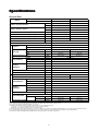
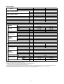
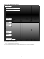
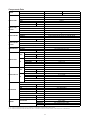
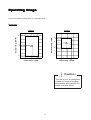
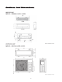
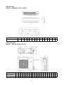
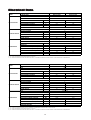
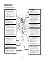
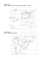
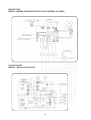
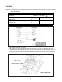
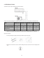
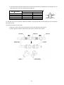
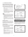
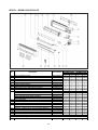
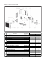
Contents
Nomenclature ............................................................................................................... 1
Features ........................................................................................................................ 3
Product Line-up ............................................................................................................ 4
Specifications ............................................................................................................... 5
Operating Range ......................................................................................................... 11
Outlines And Dimensions ........................................................................................... 12
Electrical Data.............................................................................................................. 14
Controller ..................................................................................................................... 16
Wiring Diagrams .......................................................................................................... 17
Refrigerant Circuit Diagram ....................................................................................... 21
Installation ................................................................................................................... 23
Servicing And Maintenance ........................................................................................ 35
Troubleshooting .......................................................................................................... 37
Exploded View And Parts List .................................................................................... 45
Note : Installation and maintenance are to be performed only by qualified personnel who are
familiar with local codes and regulations, and experienced with this type of equipment.
Caution: Sharp edges and coil surfaces are a potential injury hazard. Avoid contact with them.
Warning : Moving machinery and electrical power hazard. May cause severe personal
injury or death. Disconnect and lock off power before servicing equipment.
"McQuay" is a registered trademark of McQuay International. All rights reserved.
c 2006 McQuay International. All rights reserved throughout the world.
Bulletin illustrations cover the general appearance of McQuay International products at the time of publication.
We reserve the right to change design and construction specifications at any time without notice.
Nomenc
la
tur
e
Nomencla
latur
ture
Indoor
Others
A : First issue
Contoller Type
L : Longertech E-scroll
T : OYL E-Scroll
U : OYL DC1P
Air Treatment Devices & Control
I : Negative Ion with wireless controller
N : NTP with wireless controller
X : Oxygen unit
Market Region
C : Export with CE mark
U : UTL Spec.
Electrical
A : 220 - 240V/1Ph/50Hz
M
5
WM
X
010
G
R
-
A
C
I
Model Type
R : heatpump
Omitted if Cooling
Series
G : G series
Capacity
010 : 9,000 Btu/h
System
X : DC Inverter
Model Name
WM : Wall Mounted
Refrigerant
5 : R410A
Brand
M : McQuay
1
L
A
Outdoor
Others
A : First issue
Contoller Type
L : Longertech E-scroll
T : OYL E-scroll
U : OYLDC1P
Air Treatment Devices & Control
O
G
H
I
L
S
X
: Standard unit
: Low ambient unit
: High ambient unit
: Gold fins
: Long piping unit
: With H/L pressure switch
: Oxygen unit
Market Region
C : Export with CE mark
E : Export without marking
U : UTL Spec.
Electrical
A : 220 - 240V/1Ph/50Hz
M
5
LC
X
010
C
-
R
A
C
O
Model Type
R : heatpump
Omitted if Cooling
Series
C : C series
Capacity
010 : 9,000 Btu/h
System
X : DC Inverter
Model Name
LC : Condensing unit
Refrigerant
5 : R410A
Brand
M : McQuay
2
L
A
Fea
tur
es
eatur
tures
Energy Saving
Total energy saved can be as high as 30% compared to the conventionally controlled units.
Efficient
McQuay DC Inverter series achieve excellent efficient with high EER & COP rating.
Comfortable
Users enjoy better comfort and quietness with inverter technology. When the environmental factors, such as
temperature, humidity, airflow and/or outside ambient conditions, are obtained and processed through a control algorithm, the compressor motor speed can be varied to optimize the cooling power to create a more
precisely controlled room temperature (i.e. less temperature fluctuation).
R410A Refrigerant (New)
Introducing the new type of refrigerant - R410A which is environmental friendly with Zero Ozone Depletion
Potential (ODP = 0). R410A also provides the higher volumetric capacity and better refrigerating effect per unit
of volume.
Advance Technology
The traditional conventional air conditioners repeat "the start" and "the stop" during the thermostat cycle off and
causes the room temperature to be unstable. Incorporating fuzzy logic control into the McQuay Inverter design
enables greater flexibility in handling the system control.
This result in:
- Powerful, efficient and economical operation.
- Even room temperature control.
- Constant and quiet compressor operation.
- Enhanced system reliability and reduced maintenance costs.
Self Diagnostic
Both indoor and outdoor LED Error Code Indicator helps to simplify the trouble shooting process. Where there's
fault detected during operation, the defect code will be to indicate the faults.
Wireless Remote Control
-
The compact LCD transmitter is able to operate the air conditioner unit within the distance of 9 meters.
Fan motor speed can be set at low / medium / high or automatic.
Sleep mode automatically increase set temperature since room temperature is lower at night thus
achieving comfort surrounding.
Airflow direction can be controlled automatically.
Room temperature is controlled by electronic thermostat.
The unit can be preset to on and off automatically for maximum of 15 hours by using timer on/off.
Introducing turbo mode, which allows inverter compressor operates at high power and maximum
speed to achieve required temperature quickly.
3
025CR 020CR
015CR
Heat Pump Model
010CR
ACOLA
X
ACOTA
X
ACILA
X
ACITA
X
X
X
ACOLA
X
X
X
X
X
ACILA
X
X
X
X
ACOLA
X
X
X
X
ACILA
X
X
X
X
ACOUA
X
ACOLA
X
ACOTA
X
ACILA
X
ACITA
X
ACOUA
X
X
X
X
X
X
X
Nomenclature
M5WMX
Anti-Microbial Filter
Air Filter (Titanium Oxide)
X
X
X
X
X
X
X
X
X
X
X
X
X
X
X
X
X
X
X
X
X
X
X
X
X
X
X
X
X
X
4
X
CE
Auto Restart
Non-Thermal Plasma (NTP)
Negative Ion
X
X
X
X
X
X
X
X
X
X
X
X
X
Gold Fin
X
ACILA
X
Fin
X
Marking
Air Purification
X
Marking
X
X
CE
ACNLA
X
Hydrophilic Fin
X
X
Compressor
X
X
Scroll
X
Ionizer Filter
ACILA
Control Module
X
X
LJID 1.0
X
X
Handset
X
X
G12
ACILA
ACNLA
X
Rotary
Printed Circuit
Board
Refrigerant
Control
010GR
015GR
Heat Pump Model
ACNLA
020GR
025GR
ACNLA
ACILA
VB 2.0 (Inverter)
DC Inverter (LJ DSCAA)
Electronic Expansion Device
Capillary Tube
Nomenclature
M5LCX
Pr
oduct Line-Up
Product
M5WMX Product line-up
Classification
X
X
X
X
X
X
X
X
X
X
X
X
X
X
X
X
X
X
X
M5LCX Product line-up
Classification
X
X
X
X
X
X
X
X
X
X
X
X
X
X
X
X
X
Specif
ica
tions
Specifica
ications
General Data
MODEL
INDOOR UNIT
M5WMX 015GR
M5WMX 010GR
OUTDOOR UNIT
Btu/h
NOMINAL COOLING CAPACITY
NOMINAL HEATING CAPACITY
M5LCX 010CR
M5LCX 015CR
9,000 (3,700 - 12,000)
12,000 (3,700 - 15,000)
W
2,638 (1,084 - 3,517)
3,517 (1,084 - 4,396)
Btu/h
11,500 (4,000 - 15,000)
14,000 (4,000 - 17,000)
W
3,370 (1,172 - 4,980)
4,103 (1,172 - 4,982)
NOMINAL TOTAL INPUT POWER (COOLING)
W
780 (300 - 1,100)
1,095 (300 - 1,780)
NOMINAL TOTAL INPUT POWER (HEATING)
W
980 (290 - 1,680)
1,270 (290 - 1,950)
NOMINAL RUNNING CURRENT (COOLING)
A
3.8
5.4
NOMINAL RUNNING CURRENT (HEATING)
A
4.8
6.3
POWER SOURCE
220-240/1/50
V/Ph/Hz
R410A
REFRIGERANT TYPE
CONTROL
INDOOR UNIT
AIR FLOW
AIR DISCHARGE
OPERATION
WIRELESS LCD REMOTE CONTROL
HIGH
CFM / L/s
300 / 142
330 / 156
MEDIUM
CFM / L/s
250 / 118
260 / 123
LOW
CFM / L/s
200 / 94
210 / 99
dBA
38 / 35 / 30
SOUND PRESSURE (H/M/L)
UNIT DIMENSION
PACKING
DIMENSION
mm/in
260.0 / 10.2
WIDTH
mm/in
899.0 / 35.4
DEPTH
mm/in
198.0 / 7.8
HEIGHT
mm/in
337.0 / 13.3
WIDTH
mm/in
957.0 / 37.7
DEPTH
mm/in
270.0 / 10.6
UNIT WEIGHT
AIR FLOW
SOUND PRESSURE
OUTDOOR UNIT
PACKING
DIMENSION
kg/lb
9.5 / 21.0
mm/in
16.0 / 0.63
CFM / L/s
800 / 378
dBA
47
900 / 425
52
HEIGHT
mm/in
540 / 21.3
WIDTH
mm/in
700 (+70) / 27.6 (+2.8)
DEPTH
mm/in
250 / 9.8
HEIGHT
mm/in
601 / 23.7
WIDTH
mm/in
803 / 31.6
DEPTH
mm/in
320 / 12.6
UNIT WEIGHT
38 / 84
kg/lb
TYPE
PIPE CONNECTION
39 / 36 / 31
HEIGHT
CONDENSATE DRAIN SIZE
UNIT DIMENSION
LOUVER (UP & DOWN) & GRILLE (LEFT & RIGHT)
SIZE
REFRIGERANT CHARGE
FLARE
LIQUID
mm/in
6.35 / ¼
GAS
mm/in
9.52 / 3/8
6.35 / ¼
12.7 / ½
kg/lb
0.89 / 1.87
0.90 / 1.98
1) ALL SPECIFICATIONS ARE SUBJECTED TO CHANGE BY THE MANUFACTURER WITHOUT PRIOR NOTICE.
2) ALL UNITS ARE BEING TESTED AND COMPLY TO ISO 5151.
3) NOMINAL COOLING AND HEATING CAPACITY ARE BASED ON THE CONDITIONS BELOW :
a) COOLING - 27°C DB / 19°C WB INDOOR AND 35°C DB / 24°C WB OUTDOOR
b) HEATING - 20°C DB INDOOR AND 7°C DB / 6°C WB OUTDOOR
4) SOUND PRESSURE LEVEL ARE ACCORDING TO JIS B 8615 STANDARD. POSITION OF THE MEASUREMENT POINT IS 1m IN FRONT AND 1m BELOW THE UNIT.
5) ALL SPECIFICATION ARE TENTATIVE SPECIFICATION AT THE TIME OF PRINTING. PLEASE CONSULT YOUR DEALER FOR CONFIRMATION.
6) SOUND SPECTRUM FOR MWMX010GR / MWMX015GR IS NOT AVAILABLE AT THE TIME OF PRINTING
5
General Data
MODEL
INDOOR UNIT
M5WMX 020GR
M5WMX 025GR
OUTDOOR UNIT
M5LCX 020CR
M5LCX 025CR
Btu/h
18,000 (5,000 - 20,000)
21,000 (5,000 - 23,000)
W
5,275 (1,465 - 5,862)
6,155 (1,465 - 6,741)
Btu/h
19,000 (5,000 - 22,000)
22,000 (5,000 - 25,000)
NOMINAL COOLING CAPACITY
NOMINAL HEATING CAPACITY
W
5,568 (1,465 - 6,155)
6,448 (1,465 - 7,034)
NOMINAL TOTAL INPUT POWER (COOLING)
W
1,636
2,150
NOMINAL TOTAL INPUT POWER (HEATING)
W
1,652
2,200
NOMINAL RUNNING CURRENT (COOLING)
A
7.9
11.3
A
8.0
NOMINAL RUNNING CURRENT (HEATING)
POWER SOURCE
11.8
220-240 / 1 / 50
V/Ph/Hz
REFRIGERANT TYPE
CONTROL
INDOOR UNIT
AIR FLOW
R410A
AIR DISCHARGE
WIRELESS LCD REMOTE CONTROL
HIGH
CFM / L/s
550 / 260
630 / 297
MEDIUM
CFM / L/s
440 / 208
500 / 236
LOW
CFM / L/s
370 / 175
420 / 198
dBA
44 / 40 / 35
49 / 43 / 40
SOUND PRESSURE (H/M/L)
UNIT DIMENSION
PACKING
DIMENSION
HEIGHT
mm/in
304.0 / 12.0
WIDTH
mm/in
1062.0 / 41.8
DEPTH
mm/in
220.0 / 8.7
HEIGHT
mm/in
378.0 / 14.9
WIDTH
mm/in
1130.0 / 44.5
DEPTH
mm/in
292.0 11.5
kg/lb
15.0 / 33.1
mm/in
20.0 / 0.79
UNIT WEIGHT
CONDENSATE DRAIN SIZE
AIR FLOW
SOUND PRESSURE
OUTDOOR UNIT
UNIT DIMENSION
PACKING
DIMENSION
LOUVER (UP & DOWN) & GRILLE (LEFT & RIGHT)
OPERATION
CFM / L/s
1500 / 708
1600 / 755
dBA
53
56
654 / 25.7
HEIGHT
mm/in
WIDTH
mm/in
855 (+70) / 33.7 (+2.7)
DEPTH
mm/in
328 / 12.9
HEIGHT
mm/in
785 / 30.9
WIDTH
mm/in
983 / 38.7
DEPTH
mm/in
405 / 15.9
kg/lb
50 / 110
UNIT WEIGHT
FLARE
TYPE
PIPE CONNECTION
SIZE
REFRIGERANT CHARGE
757 / 6.7
LIQUID
GAS
mm/in
6.35 / ¼
6.35 / ¼
mm/in
12.7 / ½
15.8 / 5/8
kg/lb
1.3 / 2.87
1.4 / 3.09
1) ALL SPECIFICATIONS ARE SUBJECTED TO CHANGE BY THE MANUFACTURER WITHOUT PRIOR NOTICE.
2) ALL UNITS ARE BEING TESTED AND COMPLY TO ISO 5151.
3) NOMINAL COOLING AND HEATING CAPACITY ARE BASED ON THE CONDITIONS BELOW :
a) COOLING - 27°C DB / 19°C WB INDOOR AND 35°C DB / 24°C WB OUTDOOR
b) HEATING - 20°C DB INDOOR AND 7°C DB / 6°C WB OUTDOOR
4) SOUND PRESSURE LEVEL ARE ACCORDING TO JIS B 8615 STANDARD. POSITION OF THE MEASUREMENT POINT IS 1m IN FRONT AND 1m BELOW THE UNIT.
5) ALL SPECIFICATION ARE TENTATIVE SPECIFICATION AT THE TIME OF PRINTING. PLEASE CONSULT YOUR DEALER FOR CONFIRMATION.
6) SOUND SPECTRUM FOR MWMX020GR / MWMX025GR IS NOT AVAILABLE AT THE TIME OF PRINTING
6
General Data (With Torque Control)
MODEL
INDOOR UNIT
M5WMX 010GR
M5WMX 015GR
OUTDOOR UNIT
M5LCX 010CR
M5LCX 015CR
Btu/h
9,500 (2,772 - 11,165)
12,000 (2,772 - 15,114)
W
2,784 (812 - 3,272)
3,517 (812 - 4,430)
Btu/h
11,500 (2,699 - 15,655)
13,000 (2,699 - 16,170)
NOMINAL COOLING CAPACITY
NOMINAL HEATING CAPACITY
W
3,370 (791 - 4,588)
3,810 (791 - 4,739)
NOMINAL TOTAL INPUT POWER (COOLING)
W
820 (242 - 1,038)
1,100 (242 - 1,559)
NOMINAL TOTAL INPUT POWER (HEATING)
W
930 (231 - 1,455)
1,057 (231 - 1,865)
NOMINAL RUNNING CURRENT (COOLING)
A
3.9
5.3
A
4.5
NOMINAL RUNNING CURRENT (HEATING)
INDOOR UNIT
POWER SOURCE
REFRIGERANT TYPE
INDOOR AIR FLOW
R410A
HIGH
CFM / L/s
300 / 142
330
MEDIUM
CFM / L/s
250 / 118
260
LOW
CFM / L/s
200 / 94
210
dBA
38 / 35 / 30
39 / 36 / 31
INDOOR SOUND PRESSURE (H/M/L)
INDOOR UNIT
DIMENSION
INDOOR PACKING
DIMENSION
HEIGHT
mm/in
260 / 10.2
WIDTH
mm/in
899 / 35.4
DEPTH
mm/in
198 / 7.8
HEIGHT
mm/in
337 / 13.3
WIDTH
mm/in
957 / 37.7
DEPTH
mm/in
270 / 10.6
INDOOR UNIT WEIGHT
CONDENSATE DRAIN SIZE
OUTDOOR AIR FLOW
OUTDOOR SOUND PRESSURE
OUTDOOR UNIT
DIMENSION
OUTDOOR UNIT
5.0
220-240/1/50
V/Ph/Hz
kg/lb
9.5 / 21
mm/in
16 / 0.63
CFM / L/s
800 / 378
900 / 425
dBA
47
52
HEIGHT
mm/in
540 / 21.3
WIDTH
mm/in
700 (+70) / 27.6 (+2.8)
DEPTH
mm/in
250 / 9.8
HEIGHT
mm/in
601 / 23.7
mm/in
803 / 31.6
mm/in
320 / 12.6
kg/lb
38
OUTDOOR PACKING
WIDTH
DIMENSION
DEPTH
OUTDOOR UNIT WEIGHT
TYPE
PIPE CONNECTION
SIZE
REFRIGERANT CHARGE
FLARE
6.35 / ¼
6.35 / ¼
LIQUID
mm/in
GAS
mm/in
9.52 / 3/8
12.7 / ½
kg/lb
0.80 / 1.76
0.94 / 2.07
1) ALL SPECIFICATIONS ARE SUBJECTED TO CHANGE BY THE MANUFACTURER WITHOUT PRIOR NOTICE.
2) ALL UNITS ARE BEING TESTED AND COMPLY TO ISO 5151.
3) NOMINAL COOLING AND HEATING CAPACITY ARE BASED ON THE CONDITIONS BELOW :
a) COOLING - 27°C DB / 19°C WB INDOOR AND 35°C DB / 24°C WB OUTDOOR
b) HEATING - 20°C DB INDOOR AND 7°C DB / 6°C WB OUTDOOR
4) SOUND PRESSURE LEVEL ARE ACCORDING TO JIS B 8615 STANDARD. POSITION OF THE MEASUREMENT POINT IS 1m IN FRONT AND 1m BELOW THE UNIT.
5) ALL SPECIFICATION ARE TENTATIVE SPECIFICATION AT THE TIME OF PRINTING. PLEASE CONSULT YOUR DEALER FOR CONFIRMATION.
7
Components Data
MODEL
INDOOR UNIT
M5WMX 010GR
OUTDOOR UNIT
M5LCX 010CR
1
Q'TY
INDOOR FAN
MOTOR
ACRYLO NITRILE STYRENE
MATERIAL
DIRECT
DRIVE
DIAMETER
mm/in
LENGTH
mm/in
97.0 / 3.8
717.5 / 28.2
SCR MOTOR
TYPE
1
Q'TY
IP24
INDEX OF PROTECTION (IP)
PROPELLER FAN
TYPE
1
Q'TY
GLASS REINFORCED ACRLY STYRENE RESIN
OUTDOOR FAN MATERIAL
DIRECT
DRIVE
DIAMETER
406.0 / 16.0
mm/in
INDUCTION
TYPE
OUTDOOR FAN
Q'TY
MOTOR
INDEX OF PROTECTION (IP)
1
IP33
DC BRUSHLESS SCROLL
TYPE
COMPRESSOR
POLYOESTER OIL (POE)
OIL TYPE
OIL AMOUNT
360
cm³
SEAMLESS COPPER
MATERIAL
TUBE
DIAMETER
mm/in
7.0 / 0.276
THICKNESS
mm/in
0.28 / 0.011
ALUMINIUM (HYDROPHILIC)
MATERIAL
INDOOR COIL
FIN
THICKNESS
mm/in
FACE AREA
m /ft
2
0.11 / 0.0043
2
0.193 / 2.08
ROW
2
FIN PER INCH
18
SEAMLESS INNER GROOVED COPPER
MATERIAL
TUBE
DIAMETER
mm/in
7.0 / 0.276
THICKNESS
mm/in
0.32 / 0.013
ALUMINIUM (HYDROPHILIC)
MATERIAL
OUTDOOR COIL
FIN
THICKNESS
mm/in
FACE AREA
m /ft
2
0.11 / 0.0043
2
0.350 / 3.78
ROW
2
FIN PER INCH
18
SARANET
TYPE
QUANTITY
DIMENSION ( L x W x t )
pc
2
mm/in
386 x 364.3 x 1.5 / 15.2 x 14.3 x 0.06
ANTI-MICROBIAL
TYPE
FILTRATION
M5LCX 015CR
CROSS FLOW
TYPE
INDOOR FAN
M5WMX 015GR
QUANTITY
DIMENSION ( L x W x t )
pc
1
mm/in
248 x 43 x 5 / 9.8 x 1.7 x 0.2
TITANIUM OXIDE
TYPE
QUANTITY
DIMENSION ( L x W x t )
INDOOR UNIT
CASING
OUTDOOR UNIT
pc
1
mm/in
248 x 43 x 5 / 9.8 x 1.7 x 0.2
MATERIAL
HIGH IMPACT POLYSTYRENE
COLOUR
LIGHT GREY
MATERIAL
GALVANISED MILD STEEL
COLOUR
LIGHT GREY
1) ALL SPECIFICATION ARE SUBJECTED TO CHANGE BY THE MANUFACTURER WITHOUT PRIOR NOTICE
2) ALL SPECIFICATION ARE TENTATIVE SPECIFICATION AT THE TIME OF PRINTING. PLEASE CONSULT YOUR DEALER FOR CONFIRMATION.
8
Components Data
MODEL
INDOOR UNIT
M5WMX 020GR
OUTDOOR UNIT
M5LCX 020CR
1
Q'TY
INDOOR FAN
MOTOR
ACRYLO NITRILE STYRENE
MATERIAL
DIRECT
DRIVE
DIAMETER
mm/in
LENGTH
mm/in
108.0 / 4.3
810.0 / 32.9
SCR MOTOR
TYPE
1
Q'TY
IP54
INDEX OF PROTECTION (IP)
PROPELLER
TYPE
1
Q'TY
GLASS REINFORCED ACRYL STYRENE RESIN
OUTDOOR FAN MATERIAL
DIRECT
DRIVE
DIAMETER
460.0 / 18
mm/in
INDUCTION
TYPE
OUTDOOR FAN
Q'TY
MOTOR
INDEX OF PROTECTION (IP)
1
IP22
DC BRUSHLESS SCROLL
TYPE
COMPRESSOR
POLYOESTER OIL (POE)
OIL TYPE
OIL AMOUNT
480
cm³
SEAMLESS COPPER TUBE
MATERIAL
TUBE
DIAMETER
mm/in
7.0 / 0.276
THICKNESS
mm/in
0.28 / 0.011
ALUMINIUM (HYDROPHILIC)
MATERIAL
INDOOR COIL
FIN
THICKNESS
mm/in
FACE AREA
m /ft
2
0.11 / 0.0043
2
0.269 / 2.90
ROW
2
FIN PER INCH
18
SEAMLESS INNER GROOVED COPPER TUBE
MATERIAL
TUBE
DIAMETER
mm/in
7.0 / 0.276
THICKNESS
mm/in
0.32 / 0.013
ALUMINIUM (HYDROPHILIC)
MATERIAL
OUTDOOR COIL
FIN
THICKNESS
mm/in
FACE AREA
m /ft
2
0.11 / 0.0043
2
0.62 / 6.67
ROW
2
FIN PER INCH
20
SARANET
TYPE
QUANTITY
DIMENSION ( L x W x t )
pc
2
mm/in
386 x 364.3 x 1.5 / 15.2 x 14.3 x 0.06
ANTI-MICROBIAL
TYPE
FILTRATION
M5LCX 025CR
CROSS FLOW
TYPE
INDOOR FAN
M5WMX 025GR
QUANTITY
DIMENSION ( L x W x t )
pc
1
mm/in
248 x 43 x 5 / 9.8 x 1.7 x 0.2
TITANIUM OXIDE
TYPE
QUANTITY
DIMENSION ( L x W x t )
INDOOR UNIT
CASING
OUTDOOR UNIT
pc
1
mm/in
248 x 43 x 5 / 9.8 x 1.7 x 0.2
MATERIAL
HIGH IMPACT POLYSTYRENE
COLOUR
LIGHT GREY
MATERIAL
GALVANISED MILD STEEL
COLOUR
LIGHT GREY
1) ALL SPECIFICATION ARE SUBJECTED TO CHANGE BY THE MANUFACTURER WITHOUT PRIOR NOTICE
2) ALL SPECIFICATION ARE TENTATIVE SPECIFICATION AT THE TIME OF PRINTING. PLEASE CONSULT YOUR DEALER FOR CONFIRMATION.
9
Components Data (With Torque Control)
MODEL
INDOOR UNIT
M5WMX 010GR
OUTDOOR UNIT
M5LCX 010CR
1
Q'TY
INDOOR FAN
MOTOR
ACRYLO NITRILE STYRENE
MATERIAL
DIRECT
DRIVE
DIAMETER
mm/in
LENGTH
mm/in
97 / 3.8
717.5 / 28.2
SCR MOTOR
TYPE
1
Q'TY
IP24
MOTOR PROTECTION
PROPELLER FAN
TYPE
1
Q'TY
GLASS REINFORCED ACRLY STYRENE RESIN
OUTDOOR FAN MATERIAL
DIRECT
DRIVE
DIAMETER
406 / 16
mm/in
PERMANENT SPLIT CAPACITOR INDUCTION
TYPE
OUTDOOR FAN
Q'TY
MOTOR
MOTOR PROTECTION
1
IP33
DC ROTARY
TYPE
COMPRESSOR
Polyoester oil (POE)
OIL TYPE
OIL AMOUNT
320
cm³
SEAMLESS COPPER
MATERIAL
TUBE
DIAMETER
mm/in
7 / 0.276
THICKNESS
mm/in
0.28 / 0.011
ALUMINIUM (HYDROPHILIC)
MATERIAL
INDOOR COIL
FIN
THICKNESS
mm/in
FACE AREA
m /ft
2
0.11 / 0.0043
2
0.193 / 2.08
ROW
2
FIN PER INCH
18
SEAMLESS INNER GROOVED COPPER
MATERIAL
TUBE
DIAMETER
mm/in
7 / 0.276
THICKNESS
mm/in
0.32 / 0.013
ALUMINIUM (HYDROPHILIC)
MATERIAL
OUTDOOR COIL
FIN
THICKNESS
mm/in
FACE AREA
m /ft
2
0.11 / 0.0043
2
0.35 / 3.78
2
ROW
18
FIN PER INCH
SARANET
TYPE
QUANTITY
FILTRATION
M5LCX 015CR
CROSS FLOW
TYPE
INDOOR FAN
M5WMX 015GR
2
pc
ANTI-MICROBIAL
TYPE
QUANTITY
1
pc
TITANIUM OXIDE
TYPE
QUANTITY
INDOOR UNIT
CASING
OUTDOOR UNIT
pc
1
MATERIAL
HIGH IMPACT POLYSTYRENE
COLOUR
LIGHT GREY
MATERIAL
GALVANISED MILD STEEL
COLOUR
LIGHT GREY
1) ALL SPECIFICATION ARE SUBJECTED TO CHANGE BY THE MANUFACTURER WITHOUT PRIOR NOTICE
2) ALL SPECIFICATION ARE TENTATIVE SPECIFICATION AT THE TIME OF PRINTING. PLEASE CONSULT YOUR DEALER FOR CONFIRMATION.
10
Oper
ating R
ang
e
Opera
Rang
ange
Ensure the operating temperature is in allowable range.
Heatpump
Heating
Cooling
Outdoor temp. (°CDB)
Outdoor temp. (°CWB)
18
6
STD
46
35
STD
19
0
-9
15
21
27
15
24
Indoor temp. (°CWB)
Indoor temp. (°CDB)
Caution :
The use of your air conditioner
outside the range of working
temperature and humidity can
result in serious failure.
11
Outlines And Dimensions
INDOOR UNIT
MODEL : M5WMX 010GR / 015GR
Note : Dimension in mm
OUTDOOR UNIT
MODEL : M5LCX 010CR / 015CR
Note : Dimension in mm
12
INDOOR UNIT
MODEL : M5WMX 020GR / 025GR
MODEL
A
B
1062
M5WMX 020/025 GR
C
D
E
304 220 912 294
F
G
H
I
J
K
99
51
8
48
43
L
M
N
O
354 403 160 138 160
Note : Dimension in mm
OUTDOOR UNIT
MODEL : M5LCX 020CR / 025CR
FOR M5LCX025C/CR ONLY
MODEL
F
G
N
O
P
Q
R
S
T
M5LCX 020 CR
855
A
628 328 508 181
B
C
D
E
44
93
149 101 113 603 126 164
H
I
J
K
L
M
17
49
32
3
23
73
75
M5LCX 025 CR
855
730 328 513 182
44
93
149 101 113 603 126 164
17
47
32
3
23
73
75
Note : Dimension in mm
13
Electrical Da
ta
Data
MODEL
INDOOR UNIT
M5WMX 010GR
M5WMX 015GR
OUTDOOR UNIT
M5LCX 010CR
M5LCX 015CR
TYPE
SCR
INSULATION GRADE
POWER SOURCE
INDOOR MOTOR
E
V/Ph/Hz
230 / 1 / 50
RATED INPUT POWER
W
38
40
RATED RUNNING CURRENT
A
0.19
0.20
MOTOR OUTPUT
W
17
POLES
PERMANENT SPLIT CAPACITOR
INSULATION GRADE
OUTDOOR MOTOR
B
V/Ph/Hz
230 / 1 / 50
230 / 1 / 50
RATED INPUT POWER
W
56
71
RATED RUNNING CURRENT
A
0.24
0.31
MOTOR OUTPUT
W
25
TYPE
POWER SOURCE
35
INVERTER
INSULATION GRADE
COMPRESSOR
17
4P
TYPE
POWER SOURCE
230 / 1 / 50
E
230 / 1 / 50
V/Ph/Hz
CAPACITOR
µF
RATED INPUT POWER (COOLING)
W
686
984
RATED INPUT POWER (HEATING)
W
886
1159
RATED RUNNING CURRENT (COOLING)
A
3.4
5.4
RATED RUNNING CURRENT (HEATING)
A
4.4
4.9
LOCKED ROTOR AMP.
A
-
40
1) ALL SPECIFICATION ARE SUBJECTED TO CHANGE BY THE MANUFACTURER WITHOUT PRIOR NOTICE.
2) ALL UNITS ARE BEING TESTED AND COMPLY TO ISO 5151.
3) ALL SPECIFICATION ARE TENTATIVE SPECIFICATION AT THE TIME OF PRINTING. PLEASE CONSULT YOUR DEALER FOR CONFIRMATION.
MODEL
INDOOR UNIT
M5WMX 020GR
OUTDOOR UNIT
M5LCX 020CR
TYPE
INDOOR MOTOR
B
230 / 1 / 50
V/Ph/Hz
RATED INPUT POWER
W
60
75
RATED RUNNING CURRENT
A
0.31
0.40
MOTOR OUTPUT
W
40
POLES
PERMANENT SPLIT CAPACITOR
INSULATION GRADE
POWER SOURCE
E
V/Ph/Hz
230 / 1 / 50
RATED INPUT POWER
W
130
140
RATED RUNNING CURRENT
A
0.58
0.58
MOTOR OUTPUT
W
75
TYPE
POWER SOURCE
230 / 1 / 50
80
INVERTER
INSULATION GRADE
COMPRESSOR
40
4
TYPE
OUTDOOR MOTOR
M5LCX 025CR
SCR
INSULATION GRADE
POWER SOURCE
M5WMX 025GR
E
230 / 1 / 50
V/Ph/Hz
CAPACITOR
µF
RATED INPUT POWER (COOLING)
W
1440
1775
RATED INPUT POWER (HEATING)
W
1430
1785
RATED RUNNING CURRENT (COOLING)
A
7.0
9.5
RATED RUNNING CURRENT (HEATING)
A
6.9
10.0
LOCKED ROTOR AMP.
A
-
30
1) ALL SPECIFICATION ARE SUBJECTED TO CHANGE BY THE MANUFACTURER WITHOUT PRIOR NOTICE.
2) ALL UNITS ARE BEING TESTED AND COMPLY TO ISO 5151.
3) ALL SPECIFICATION ARE TENTATIVE SPECIFICATION AT THE TIME OF PRINTING. PLEASE CONSULT YOUR DEALER FOR CONFIRMATION.
14
Electrical Data (With Torque Control)
MODEL
INDOOR UNIT
M5WMX 010GR
OUTDOOR UNIT
M5LCX 010CR
TYPE
INDOOR MOTOR
E
V/Ph/Hz
230 / 1 / 50
RATED INPUT POWER
W
38
40
RATED RUNNING CURRENT
A
0.19
0.20
MOTOR OUTPUT
W
17
POLES
B
V/Ph/Hz
230 / 1 / 50
RATED INPUT POWER
W
56
71
RATED RUNNING CURRENT
A
0.24
0.31
MOTOR OUTPUT
W
25
TYPE
POWER SOURCE
230 / 1 / 50
35
DC ROTARY
INSULATION GRADE
COMPRESSOR
17
PERMANENT SPLIT CAPACITOR INDUCTION
INSULATION GRADE
POWER SOURCE
230 / 1 / 50
4P
TYPE
OUTDOOR MOTOR
M5LCX 015CR
SCR MOTOR
INSULATION GRADE
POWER SOURCE
M5WMX 015GR
E
230 / 1 / 50
V/Ph/Hz
CAPACITOR
µF
RATED INPUT POWER (COOLING)
W
726
989
RATED INPUT POWER (HEATING)
W
836
929
A
3.5
4.8
RATED RUNNING CURRENT (HEATING)
A
4.1
LOCKED ROTOR AMP.
A
RATED RUNNING CURRENT (COOLING)
-
4.5
40
1) ALL SPECIFICATION ARE SUBJECTED TO CHANGE BY THE MANUFACTURER WITHOUT PRIOR NOTICE.
2) ALL UNITS ARE BEING TESTED AND COMPLY TO ISO 5151.
3) ALL SPECIFICATION ARE TENTATIVE SPECIFICATION AT THE TIME OF PRINTING. PLEASE CONSULT YOUR DEALER FOR CONFIRMATION.
15
Contr
oller
Controller
G11 Remote Controller
Temperature Setting
On/Off Button
•
•
Press Once to start the air
conditioner
•
Press again to stop the unit
To set the desired room
temperature, press the button to
increase or decrease the set
temperature.
•
The temperature setting range is
from 16°C to 30°C
•
Press both buttons simultaneously
to toggle the temperature setting
between °C and °F
Personalised Setting
•
Press and hold the button for 3s to
initiate personalized setting.
•
Set the individual setting e.g.
MODE, SET TEMP or FAN
SPEED and leave for 4s to save
•
2 groups of settings are allowed to
stored in the handset
Turbo Mode
•
Press the TURBO button to
achieve the required set
temperature in a short time.
Fan Speed Selection
Sleep Mode
•
•
•
•
Press the button to activate sleep
mode. This function is available
under COOL, HEAT & AUTO
mode.
Press the button until the desired
fan speed is achieved.
Operating Mode
When it is activated in COOL
mode, the set temperature will be
increased 0.5°C after 30mins, 1°C
after 1 hour and 2°C after 2 hours.
When it is activated in HEAT
mode, the set temperature will be
decreased 1°C after 30mins, 2°C
after 1 hour and 3°C after 2 hours.
ON Timer Setting
•
Press the MODE button to select
the type of operating mode.
•
For Cooling only unit, the available
modes are: COOL, DRY & FAN.
•
For Heatpump unit, the available
modes are: AUTO, COOL, DRY,
FAN & HEAT.
OFF Timer Setting
•
Press the SET button will activate
the on timer function.
•
•
Press the SET button will activate
the off timer function.
Set the desired on time by
pressing the SET button
continuously.
•
•
Press the CLR button to cancel the
off timer setting
Set the desired off time by
pressing the SET button
continuously.
•
Press the CLR button to cancel
the off timer setting
Clock Time Setting
•
Press button + or - to increase or
decrease the clock time.
Automatic Air Awing
•
Press the SWING button to
activate the automatic air swing
function.
•
To distribute the air to a specific
direction, press the SWING button
and wait until the louver move to
the desired direction and press the
button once again.
Ionizer
•
Press the button to activate the
negative Ion function, which will
refresh the indoor air effectively.
16
W iring Dia
grams
Diag
INDOOR UNIT
MODEL : M5WMX 010GR/015GR (WITH IONIZER)
OUTDOOR UNIT
MODEL : M5LCX 010CR/015CR
17
INDOOR UNIT
MODEL : M5WMX 010GR/015GR (WITH NON-THERMAL PLASMA)
OUTDOOR UNIT
MODEL : M5LCX 010CR/015CR
18
INDOOR UNIT
MODEL : M5WMX 020GR/025GR (WITH IONIZER)
OUTDOOR UNIT
MODEL : M5LCX 020CR/025CR
19
INDOOR UNIT
MODEL : M5WMX 020GR/025GR (WITH NON-THERMAL PLASMA)
OUTDOOR UNIT
MODEL : M5LCX 020CR/025CR
20
Refrig
er
ant Cir
cuit Dia
gram
efriger
erant
Circuit
Diag
MODEL : M5WMX 010GR/015GR c/w M5LCX 010CR/015CR
21
MODEL : M5WMX 020GR/025GR c/w M5LCX 020CR/025CR
22
Installa
tion
Installation
INSTALLATION DIAGRAM
1. SELECTION OF LOCATION AND SPACE
A) INDOOR UNIT
Install the fan coil (indoor) unit at a location with the following requirements
• Location is suitable for wiring, piping and drainage.
• No obstruction of air flow into and out of unit where cooler air can be evenly distributed.(See fig. 1)
• Ensure that air discharge is not short circuited with air intake.
• Ensure that wall is sufficiently strong, rigid, flat, perpendicular and vibration free.
• Where air filter cassette can be slides in or out easily.
• Where there is no danger of flammable gases.
• Where there is no direct sunlight on unit.
• Also to take into consideration a place for the installation of the Wireless LCD Remote Controller.
23
Figure 1
B) OUTDOOR UNIT
As condensing temperature rises, evaporating temperature rises and cooling capacity drops. In order to achieve
maximum cooling capacity, the location selected for outdoor unit should fulfill the following requirements:
• Install the condensing (outdoor) unit in such a way that hot air distributed by the outdoor condensing
unit cannot be drawn in again (as in the case of short circuit of hot discharge air). Allow sufficient
space for maintenance around the unit.
• Ensure that there is no obstruction of air flow into or out of the unit. Remove obstacles which block air
intake or discharge.
• The location must be well ventilated, so that the unit can draw in and distribute plenty of air thus
lowering the condensing temperature.
24
• A place capable of bearing the weight of the outdoor unit and isolating noise and vibration.
• A place protected from direct sunlight. Otherwise use an awning for protection, if necessary.
• The location must not be susceptible to dust or oil mist.
2. INSTALLATION CLEARANCES
• Outdoor units must be installed such that there is no short circuit of the hot discharge air or obstruction
to smooth air flow. Select the coolest possible place where intake air should not be hotter than the
outside temperature.
Dimension
Minimum distance, mm/in
A
B
C
D
300/11.8
1000/39.4
300/11.8
500/19.7
25
CAUTION :
• If the condensing unit is operated in an atmosphere containing oils(including machine oils), salt(coastal
area), sulphide gas(near hot spring, oil refinery plant), such substances may lead to failure of the
unit.
• If there is any obstacle higher than 2m, or if there is any obstruction at the upper part of the unit,
please allow more space than the figure indicated in the above table.
3. DRILLING HOLES AND MOUNTING PLATE INSTALLATION
Cautions:
i) Please check the unit weight for each model. Always ensure that the wall is sufficiently strong to withstand
the weight. If not, it is necessary to reinforce the wall with plate, beams or pillars.
ii) The unit cannot be directly fixed onto the wall or the likes. In all cases, the installation plate provided
MUST be used.
•
•
•
•
•
Paste the installation plate provided on the desired location on the wall and marks the holes location
accordingly.
Ensure that the minimum maintenance and servicing space at the top, left and right side of the unit
is reserved.
Ensure also the levelness of the installation plate.
Drill the screw mounting holes (minimum 4 screws are required).
Drill the pipe hole at the location as per plan. (This is only applicable for rear piping outlet installation).
Note: The hole should be drilled slightly lower at outdoor side as per figure below:-
•
Fix the installation plate firmly to wall, without tilting to left or right. Use a plumb line, if available.
•
Fixing methods:-
WOODEN
REINFORCED CONCRETE BUILDING
NUT ANCHOR
BOLT ANCHOR
26
4. INDOOR UNIT PREPARATION
• The refrigerant piping can be routed to the unit in 5 directions, by using the cut outs in the unit casing.
• Carefully bend the pipes to the required position to align with the hole. For right hand and rear side
draw out, hold the bottom of the piping and fix direction before shaping it to the desired position. The
condensation drain hose should be taped to the pipes with vinyl tape. The electrical cable can also be
taped to the pipes.
5. MOUNTING INDOOR UNIT
• Hook the indoor unit onto the upper portion of installation plate. (Engage the 2 hooks of rear top of the
indoor unit with the upper edge of the installation plate). Ensure the hooks are properly seated on the
installation plate by moving in left and right.
1. Hook the unit into the installation plate.
of installation.
2. Fix the rivet underneath after completion
6. WATER DRAINAGE PIPING
• The indoor drain pipe must be downward gradient for smooth drainage. Avoid situation as shown in
figure below.
27
7. CONDENSED WATER DISPOSAL OF OUTDOOR UNIT (HEAT PUMP UNIT ONLY)
• There are 2 holes on the base of Outdoor Unit for condensed water to flow out. Insert the drain elbow
to one of the holes.
• To install the drain elbow, first insert one portion of the hook to the base (portion A), then pull the drain
elbow in the direction shown by the arrow while inserting the other portion to the base. After the
installation, check to ensure that the drain elbow clings to base firmly.
• If the unit is installed in a snowy and chilly area, condensed water may freeze in the base. In such a
case, please remove plug at the bottom of unit to smooth the drainage.
28
8. WIRING
Important: The figures shown in the table are for information purpose only. They should be checked and selected
to comply with the local/national codes of regulations. This is also subject to the type of installation
and conductors used.
Model
M5WMX 010G/015G
Voltage range
M5WMX 020G/025G
220V-240V / 1 Ph / 50Hz +
Power supply cable size (mm2)
1.5
2.5
3
3
1.5
2.5
Number of wire
3
3
Recommended time delay fuse (A)
15
20
Number of wire
2
Interconnection cable size (mm )
• All wires must be firmly connected
• All wires must not touch the refrigerant piping, compressor or any moving parts of the fan motor.
• The connecting wires between the indoor unit and the outdoor unit must be clamped on the wire
clamps as shown in the figure.
• The power supply cord must be equivalent to H05RN-F (245IEC57) which is the minimum requirement.
29
9. REFRIGERANT PIPING
A) Maximum Pipe Length and Maximum Number of Bends
Always choose the shortest path for refrigerant piping and follow the recommendation as tabulated below:
Model
M5WMX010GR
M5WMX015GR
M5WMX020GR
M5WMX025GR
Maximum length, L (m/ft)
15/49
15/49
30/98
30/98
Max. elevation, H (m/ft)
5/16.4
5/16.4
8/26.2
8/26.2
Max. number of 90° bends
10
10
10
10
Liquid pipe size
¼”
¼”
¼”
¼”
Gas pipe size
3
½”
½”
5
/8”
/8”
Remarks: The refrigerant pre-charged in the outdoor unit is for piping length up to 7.62m/25ft.
B) Flare Connection
• Cut the pipe stages by stages, advancing the blade of pipe cutter slowly.
• Remove burr with the burr remover. Hold the flaring end down to prevent burrs from dropping inside
pipe.
30
• The exact length of pipe protruding from the face of the flare die is determined by the flaring tool. The
table shows the use of an imperial die and rigid die.
Pipe ∅, D (mm/in)
6.35 / 1/4”
9.52 / 3/8”
12.70 / 1/2”
15.88 / 5/8”
19.05 / 3/4”
A (mm)
Imperial
1.3
1.6
1.9
2.2
2.5
Rigid
0.7
1.0
1.3
1.7
2.0
Fix the pipe firmly on the flare die. Match the centers of both the flare die and the flaring punch, and tighten
flaring punch fully.
C) Piping Connection To The Units
• Align the center of the piping and tighten the flare nut sufficiently with fingers
• Finally, tighten the flare nut with the torque wrench until the wrench clicks.
31
10. SPECIAL PRECAUTION FOR R410A
SPECIAL PRECAUTIONS WHEN DEALING WITH REFRIGERANT R410A UNIT
1) WHAT IS NEW REFRIGERANT R410A?
R410A is a new HFC refrigerant which does not damage the ozone layer. The working pressure of this
new refrigerant is 1.6 times higher than conventional refrigerant (R22), thus proper installation / servicing
is essential.
2) COMPONENTS
Mixture weight composition R32(50%) and R125(50%)
3) CHARACTERISTIC
• R410A liquid and vapor components have different compositions when the fluid evaporates or
condenses. Hence, when leak occurs and only vapor leaks out, the composition of the refrigerant
mixture left in the system will change and subsequently affect the system performance. DO NOT add
new refrigerant to leaked system. It is recommended that the system should be evacuated thoroughly
before recharging with R410A.
• When refrigerant R410A is used, the composition will differ depending on whether it is in gaseous or
liquid phase. Hence when charging R410A, ensure that only liquid is being withdrawn from the cylinder
or can. This is to make certain that only original composition of R410A is being charged into the
system.
• POE oil is used as lubricant for R410A compressor, which is different from the mineral oil used for
R22 compressor. Extra precaution must be taken not to expose the R410A system too long to moist
air.
4) CHECK LIST BEFORE INSTALLATION/SERVICING
• Tubing
Refrigerant R410A is more easily affected by dust of moisture compared with R22, make sure to
temporarily cover the ends of the tubing prior to installation
• Compressor oil
No additional charge of compressor oil is permitted.
• Refrigerant
No other refrigerant other that R410A
• Tools (size of service port is different from R22 system)
Tools specifically for R410A only (must not be used for R22 or other refrigerant)
i)
Manifold gauge and charging hose
ii) Gas leak detector
iii) Refrigerant cylinder/charging cylinder
iv) Vacuum pump c/w adapter
v) Flare tools
vi) Refrigerant recovery machine
5) HANDLING AND INSTALLATION GUIDELINES
Like R22 system, the handling and installation of R410A system are closely similar. All precautionary
measures; such as ensuring no moisture, no dirt or chips in the system, clean brazing using nitrogen, and
thorough leak check and vacuuming are equally important requirements. However, due to its hydroscopic
POE oil, additional precautions must be taken to ensure optimum and trouble free system operation.
a) During installation or servicing, avoid prolong exposure of the internal part of the refrigerant system to
moist air. Residual POE oil in the piping and components can absorb moisture from the air.
b) Ensure that the compressor is not expose to open air for more than the recommended time specified
by its manufacturer (typically less than 10 minutes). Removed the seal plugs only when the compressor
is about to be brazed.
c) The system should be thoroughly vacuumed to 1.0 Pa ( 700mmHg) or lower. This vacuuming level is
more stringent than R22 system so as to ensure no incompressible gas and moisture in the system.
32
d) When charging R410A, ensure that only liquid is being withdrawn from the cylinder or can. This is to
ensure that only the original composition of R410A is being delivered into the system. The liquid
composition can be different from the vapor composition.
Invert cylinder
without dip-pipe
Dip-pipe
Liquid
withdrawal
f)
Normally, the R410A cylinder or can is being equipped with a dip pipe for liquid withdrawal. However,
if the dip pipe is not available, invert the cylinder or can so as to withdraw liquid from the valve at the
bottom.
33
11. VACUUMING AND CHARGING
PURGING THE PIPING AND THE INDOOR UNIT
Except for the outdoor unit which is pre-charged with
refrigerant, the indoor unit and the refrigerant
connection pipes must be air-purged because the
air containing moisture that remains in the refrigerant
cycle may cause malfunction of the compressor.
• Remove the caps from the valve and the service
port.
• Connect the center of the charging gauge to
the vacuum pump.
• Connect the charging gauge to the service port
of the 3-way valve.
• Start the vacuum pump. Evacuate for
approximately 30 minutes. The evacuation time
varies with different vacuum pump capacity.
Confirm that the charging gauge needle has
moved towards -760mmHg.
Caution
• If the gauge needle does not move to 760mmHg, be sure to check for gas leaks (using
the refrigerant detector) at flare type connection
of the indoor and outdoor unit and repair the
leak before proceeding to the next step.
• Close the valve of the charging gauge and stop
the vacuum pump.
• On the outdoor unit, open the suction valve (3
way) and liquid valve (2 way) (in anti-clockwise
direction) with 4mm key for hexagon sacked
screw.
Additional charge per meter
MODEL
ADDITIONAL CHARGE
The refrigerant is pre-charged in the outdoor unit. If
the piping length is less than 7.62m (25ft), then additional charge after vacuuming is not necessary. If the
piping length is more than 7.62m (25ft), then use the
additional charge value as indicated in the table.
M5WMX 010/015/020/025 GR
R410A
19.5 g/m
The additional refrigerant charge amount
recommended is a guideline for long piping
application. The actual charge required may be
different from the guideline due to different application
and variation in site condition.
CHARGE OPERATION
This operation must be done by using a gas cylinder
and a precise weighing machine. The additional
charge is toppedup into the outdoor unit using the
suction valve via the service port.
• Remove the service port cap.
• Connect the low pressure side of the charging
gauge to the suction service port center of the
cylinder tank and close the high pressure side
of the gauge. Purge the air from the service
hose.
• Start the air conditioner unit.
• Open the gas cylinder and low pressure charging valve.
• When the required refrigerant quantity is
pumped into the unit, close the low pressure
side and the gas cylinder valve.
• Disconnect the service hose from service port.
Put back the service port cap.
34
Ser
vicing And Maintenance
Servicing
! Warning
• Disconnect from the main power supply before servicing the air conditioner unit.
• DO NOT pull out the power cord when the power is ON. This may cause serious electrical shocks
which may result in fire hazards.
1
2
3
4
5
Off the unit
Unscrew the air discharge housing
Flip open the air discharge housing
Clean the blower
Close the air discharge housing and tighten it with screw
Service Parts
Maintenance Procedures
Indoor Air Filters
1.Remove any dust adhering to the filter by using a
vacuum cleaner or wash in lukewarm water (below
40ºC/104ºF) with a neutral cleaning detergent.
2.Rinse the filter well and dry before placing it back
onto the unit.
3.Do not use gasoline, volatile substances or
chemicals to clean the filter
At least once every
2 weeks. More
frequently if
necessary.
Indoor Unit
1.Clean any dirt or dust on the grille or panel by wiping
it with a soft cloth soaked in lukewarm water (below
40ºC/104ºF) and a neutral detergent solution.
2.Do not use gasoline, volatile substances
or chemicals to clean the indoor unit.
At least once every
2 weeks. More
frequently if
necessary.
Condensate Drain
Pan and Pipe
1.Check and clean.
Every 3 months.
Indoor Fan
1.Check for unusual noise.
As necessary
Indoor/Outdoor Coil
1.Check and remove dirt which is clogged between
fins.
2.Check and remove obstacles which hinder air flow
in and out of indoor/outdoor unit.
Every month.
35
Period
Every month.
Service Parts
Maintenance Procedures
Period
Electrical
1.Check voltage, current and wiring.
2.Check faulty contacts caused by loose connections,
foreign matters, etc.
Every 2 months
Every 2 months
Compressor
1.No maintenance needed if refrigerant circuit
remains sealed. However, check for refrigerant leak
at joints and fittings.
Every 6 months.
Compressor
Lubrication
1.Oil is factory charged. Not necessary to add oil if
circuit remains sealed.
No maintenance
required.
Fan Motors
Lubrication
1.All motors pre-lubricated and sealed at factory.
No maintenance
required.
36
Troub
leshooting
oubleshooting
When a malfunction of the air conditioner unit is detected, immediately switch off the main power supply
before proceeding with the following troubleshooting procedures.
The following are common fault conditions and simple troubleshooting tips. If any other fault conditions which
are not listed occur, contact your nearest local dealer. DO NOT attempt to troubleshoot the unit by yourself.
No
Fault conditions
Possible causes / corrective actions
1
The air conditioner unit will not resume after
power failure.
•
The auto restart function is not functioning. Please
turn on the unit with the wireless / wired controller.
2
The compressor does not operate 3 minutes
after the air conditioner unit is started.
•
•
Protection against frequent starting.
Wait for 3 or 4 minutes for the compressor to start
operating by it self.
3
The airflow is too slow or room cannot be
cooled sufficiently.
•
•
•
The air filter is dirty.
The doors and windows are opened.
The air suction and discharge of both indoor and
outdoor units are clogged or blocked.
The regulated temperature or temperature setting
is not low enough.
•
4
•
Discharge airflow has bad odor.
•
5
•
Condensation on the front air grille of the indoor
unit.
•
Cigarettes, smoke particles, perfume and others,
which might have adhered onto the coil, may
cause odor.
Contact your nearest dealer.
This is caused by air humidity after an extended
period of operation.
The set temperature is too low. Increase the
temperature setting and operate the unit at high
fan speed.
6
Water flowing out from the air conditioner.
•
Switch off the unit and contact your nearest
dealer. This might be due to tilted installation.
7
Hissing airflow sound from the air conditioner
unit during operation.
•
Liquid refrigerant flowing into the evaporator coil.
8
The wireless controller display is dim.
•
•
•
The batteries are discharged.
The batteries are not correctly inserted.
The assembly is not good.
9
Compressor operates continuously.
•
•
Dirty air filter. Clean the air filter.
Temperature setting too low (cooling). Use higher
temperature setting.
Temperature setting too high (heating), Use lower
temperature setting.
•
10
No cool air comes out during cooling cycle, or
no hot air comes out during heating cycle.
•
•
11
On heating cycle, warm air does not come out.
•
37
Temperature setting too high (cooling). Use lower
temperature setting.
Temperature setting too low (heating). Use higher
temperature setting.
Unit is in defrost mode. Heating operation will
resume after defrost cycle ends.
Diagnostic Guidelines
By means of pressure reading:
High side
Low side
●
●
High side
Low side
High side
Low side
High side
Low side
High side
Low side
Probable cause
Too high
A little high
Normal
Circuit
Too low
Data
A little low
Pressure
●
●
●
●
●
●
●
1.
2.
3.
4.
Overcharged with refrigerant.
Non-condensable gases in refrigerant circuit (e.g. air)
Obstructed air-intake / discharge.
Hot air short circuiting in outdoor unit.
1. Poor compression / no compression (compressor
defective)
2. Reversing valve leaking.
1.
2.
3.
4.
5.
6.
Undercharged with refrigerant.
Refrigerant leakage.
Air filter clogged / dirty (indoor unit).
Indoor fan locked / seized.
Defective defrost control, outdoor coil freeze up (heating).
Outdoor fan locked / seized (heating).
1.
2.
3.
4.
5.
Outdoor fan blocked (cooling).
Outdoor coil dirty (cooling).
Indoor fan locked / seized (heating).
Indoor air filter clogged / dirty (heating).
Non-condensable gases in refrigerant circuit (e.g. air)
1. Air intake temperature of indoor unit too high.
●
38
By means of diagnostic flow chart:
Generally, there are two kinds of problems, i.e. starting failure and insufficient cooling/heating. “Starting failure”
is caused by electrical defect while improper application or defects in refrigerant circuit causes “Insufficient
cooling / heating”.
i) Diagnosis of Electric Circuit
The most common causes of air conditioner failure to “start” are :
a) Voltage not within ±10% of rated voltage.
b) Power supply interrupted.
c) Improper control settings.
d) Air conditioner is disconnected from main power source.
e) Fuse blown or circuit breaker off.
39
ii ) Diagnosis of Refrigerant Circuit / Application
There might be some causes where the unit starts running but does not perform satisfactorily, i.e. insufficient
cooling. Judgement could be made by measuring temperature difference of indoor unit’s intake and discharge
air as well as running current.
Satisfactory operation with temperature difference of air intake & discharge of indoor unit
8°C to 13°C. *
( * value is for reference only )
40
Satisfactory operation with temperature difference of air intake & discharge of indoor unit
14°C to 20°C. *
( * value is for reference only )
41
INDICATOR LIGHTS
Inverter Unit
IR SIGNAL RECEIVER
When there is infrared remote control operating
signal, the signal receiver on indoor unit will made
a (beep) for signal acceptance confirmation.
IR Receiver
COOLING / HEATPUMP UNIT
The table below shows the LED indicator light for
air conditioner unit under normal operation and fault
condition. The LED indicator lights are located at
the middle of the air conditioner unit.
LED indicator lights
LED INDICATOR LIGHTS FOR COOLING UNIT /
HEATPUMP UNIT
The heat pump units is equipped with an “auto”
mode, whereby the unit will provide reasonable room
temperature by switching the unit automatically to
either “cool” mode or “heat” mode, according to the
temperature setting set by the user.
SLEEP MODE COOL / HEAT
TIMER
IONIZER / NTP
LED INDICATOR LIGHTS : NORMAL OPERATION AND FAULTY CONDITIONS FOR COOLING / HEATPUMP UNIT
Normal Operation / Fault Indication
Action
COOL/HEAT
(GREEN/RED)
/
/
/
Green
Red
Orange
Red
Green
Green
Green
Green
- ON
/
/
Cool mode
-
/
Heat mode
-
/
Auto mode in cooling/heating operation
-
Timer on
-
Sleep mode on
-
Ionizer on
-
/
Fan mode on
-
/
Dry mode on
-
Defrost operation
-
Indoor temperature sensor loose / short
Call your dealer
Coil temperature sensor loose / short
Call your dealer
Outdoor temperature sensor loose / short
Call your dealer
Compressor overload protection
Call your dealer
IPM / PFC error
Call your dealer
Outdoor total current trip / DC peak
Call your dealer
Compressor overheat / gas leak
Call your dealer
Indoor fan feedback error
Call your dealer
Communication error between indoor and outdoor
Call your dealer
- ON or OFF
- Blinking
42
Compressor Stopped Troubleshooting Instructions
1
(Applicable to Inverter System Only)
Keep the Main Power Supply ON
Open up the Outdoor Unit’s Top Panel or Service Panel
DO NOT TOUCH ANY OF THE
WIRES INSIDE THE UNIT!
Notice the Yellow LED on the P.C.Board
Count the number of blinks
indicated by the LED
Blink
Fault Indication
Corrective Action
1
OutdoorAmbient Sensor Error
Check ambient sensor wire and connection
2
Outdoor Coil Sensor Error
Check coil sensor wire and connection
3
Outdoor Discharge Sensor Error /
Compressor Overheat Indication
Check discharge sensor wire and connection / Not
enough refrigerant / Indoor overload / Outdoor fan not
functioning
4
DC Compressor Feedback
Call local dealer
5
Communication Error
Check Interconnection communication wire
6
Over Current
Call local dealer
7
No Load
Check compressor wire and connection
8
Over / UnderVoltage
Check power supply
9
DC Compressor Start Failure
Call local dealer
10
Cooling Overload
Check whether outdoor unit is blocked or not
11
Defrost
Wait till defrost is over then restart
12
IPM Protection
Check IPM
13
EEPROM Read Error
Change EEPROM
14
EEPROM Write Error
Change EEPROM
15
DC Fan Motor Feedback Error
Check fan motor wire connection
16
AC Peak Current Error
Call local dealer
17
Check suction sensor wire and connection
21
Outdoor Suction Sensor Error
DC Compressor Speed Control
Error
Outdoor Suction A Sensor Error
Check A suction sensor wire and connection
22
Outdoor Suction B Sensor Error
Check B suction sensor wire and connection
23
Outdoor Suction C Sensor Error
Check C suction sensor wire and connection
19
Call local dealer
24
Outdoor Suction D Sensor Error
Check D suction sensor wire and connection
31
Indoor A Communication Error
Check Interconnection communication wire to Indoor A
32
Indoor B Communication Error
Check Interconnection communication wire to Indoor B
33
Indoor C Communication Error
Check Interconnection communication wire to Indoor C
34
Indoor D Communication Error
Check Interconnection communication wire to Indoor D
*If the problem persist, contact your local dealer straight away
43
Normal Running Mode Condition
2
(Applicable to Inverter System Only)
If the air conditioner unit has no faulty indications and the compressor is running at normal mode, the
outdoor P.C.Board’s LED indication will blink at a slower paste. The table below shows the significant
meaning of different running mode and limitation for this air conditioner unit.
One must not attempt to see the LED indication blinking unless instructed to do so.
Blinks
Blinking Indication
1
Normal Running, with no limitation
2
Voltage Limit
3
Cooling unit : Outdoor Coil Temperature Limit
4
Total Current Limit
5
Discharge Temperature Limit
6
Cooling unit : Indoor Coil Temperature Limit
7
Indoor Fan Control
8
Outdoor Frequency Adjustment
44
Exploded Vie
w And P
ar
ts List
iew
Par
arts
MODEL : M5WMX 010GR/015GR
Related Nomenclature
No.
Description
Part Number
1
2
3
4
5
ASSY, CHASSIS 10/15G
MOTOR, MWMX10/15G-501-WL 17W WELLING
BLOWER CROSS FLOW WM10/15G G97-717.5
FAN BUSH C/FLOW BLACK
ASSY. INDOOR COIL
ASSY, INDOOR COIL - WM10GR
ASSY, INDOOR COIL - WM15GR
6 PIPING CLAMP
7 ASSY, DRAIN PAN 10/15G
8 DRAIN HOSE WM10/15(600mmL)
9 ASSY, CONTROL BOX COVER (AP)
10 ASSY, CONTROL BOX
ASSY, CONTROL BOX 10GR-IONIZER
ASSY, CONTROL BOX 10GR-NTP
ASSY, CONTROL BOX 15GR-IONIZER
ASSY, CONTROL BOX 15GR-NTP
11 ASSY,F/COVER-A
12 ASSY, AIR DISCHARGE 10/15
13 FILTER 10/15G
14 FILTER ANTI MICROBIAL
AIR FILTER, t5x248x43mm (Titanium Oxide)
15 HANDSET, WIRELESS G11 AP MCQUAY
16 ASSY, MOUNTING PLATE 10/15G
17 MOTOR, AIR SWING WM10/15G
18 LOUVER TOP 10/15G
19 LOUVER BOTTOM 10/15G
Parts not shown in diagram
STICKER, LOGO WMG MCQUAY
A50124064151
A03039022520
A03029019461
A11014029514
45
M5WMX010GR
Ionizer
NTP
9
9
9
9
9
9
9
9
M5WMX015GR
Ionizer
NTP
9
9
9
9
9
9
9
9
A50024064225
A50024066054
A12014060544
A50124064152
A10024018204
A50124074815
9
9
9
9
9
9
9
9
9
9
9
9
9
9
9
9
9
9
9
9
A50044074471
A50044074475
A50044074472
A50044074476
A50124074449
A50124062326
A12014062321
A03089019984
A03089015250
A04084067314
A50014062324
A03039021375
A12014061363
A12014061364
9
9
9
9
9
9
9
9
9
9
9
9
9
9
9
9
9
9
9
9
9
9
9
9
9
9
9
9
9
9
9
9
9
9
9
9
9
9
9
9
9
9
9
9
A08024066868
9
9
9
9
MODEL : M5WMX 020GR/025GR
No.
Description
Part Number
1
2
3
4
5
6
7
8
9
10
ASSY, CHASSIS 10/15G
ASSY, FAN MOTOR 20/25G
FAN CROSS FLOW, WM20/25F
FAN BUSH C/FLOW GREY
ASSY, COIL WM20G/GR / 5WM25G/GR
CLAMP, PIPING 20/25G
ASSY, DRAIN PAN 20/25G
DRAIN HOSE ASSY WM20C/25C(700mmL)
ASSY., CONTROL BOX COVER
ASSY, CONTROL BOX
ASSY, CONTROL BOX 20GR (IONIZER)
ASSY, CONTROL BOX 20GR (NTP)
ASSY, CONTROL BOX 25GR (IONIZER)
ASSY, CONTROL BOX 25GR (NTP)
11 ASSY,F/COVER-A
12 ASSY, AIR DISCHARGE 20/25G
13 FILTER 20/25G
14 FILTER ANTI MICROBIAL
AIR FILTER, t5x248x43mm (Titanium Oxide)
15 HANDSET, WIRELESS G11EC W/IONIZER MCQUAY
16 ASSY, MTG PLATE WM20/25F
17 LOUVER, TOP 20/25G
18 LOUVER, BOTTOM 20/25G
19 MOTOR, MP35 WM20/25G
Parts not showed in diagram
STICKER, LOGO MCQUAY (GRILLE A)
46
A50124068170
A50034074747
A03019007388
A11014023775
A50024072203
A12014071297
A50124068171
A10024015319
A50124074814
Related Nomenclature
M5WMX020GR
M5WMX025GR
Ionizer
NTP
Ionizer
NTP
9
9
9
9
9
9
9
9
9
9
9
9
9
9
9
9
9
9
9
9
9
9
9
9
9
9
9
9
9
9
9
9
9
9
9
9
A50044074736
A50044074740
A50044074737
A50044074741
A50124074743
A50124071426
A12014066832
A03089019984
A03089015250
A04084065334
A50014036133
A12014066820
A12014066821
A03039022933
9
9
9
9
9
9
9
9
9
9
9
9
9
9
9
9
9
9
9
9
9
9
9
9
9
9
9
9
9
9
9
9
9
9
9
9
9
9
9
9
9
9
9
9
A08024066868
9
9
9
9
MODEL : M5LCX 010CR/015CR
No.
1
2
3
4
5
6
7
8
9
10
11
12
13
14
Description
Related Model
Part Number
ASSY. BASE PAN
ASSY, COIL
ASSY, OUTDOOR COIL (5SLX 10CR)
ASSY, OUTER COIL (5SLX 15CR)
COMPRESSOR, ASSY 5CS102XEB MATSUSHITA
VALVE,BRACKET
VALVE, FLARE 2 WAY BRASS 1/4" (R-410A)
VALVE, FLARE 3 WAY BRASS 3/8" (R-410A)
VALVE, FLARE 3 WAY BRASS 1/2" (R-410A)
VALVE, REV 4 WAY SHF-7H-34U(RK) SHANHUA
ASSY, CAP TUBE
ASSY, CAP TUBE (5SLX10CR NEW)
ASSY, CAP TUBE (5SLX15CR NEW)
BRACKET,FAN MOTOR (SL10C/15C)
FAN MOTOR
MOTOR,M5SLX10CR-501-BOM
MOTOR, M5SLX15CR-501-BOM
FAN PROPELLER, DIA401.0 OZ42000 SHUNDE
PANEL,LEFT (SL10C/15C)
PANEL,RIGHT (SL10C/15C)
PANEL,TOP/FRONT SL10/15C
ASSY,FRONT GRILLE (SL10C/15C)
ASSY,VALVE COVER SL10C/15(R)
ASSY, CONTROL BOX
ASSY, CONTROL BOX (5SLX 10CR)
ASSY, CONTROL BOX (5SLX 15CR)
47
A50014057190
M5LCX 010CR
9
M5LCX 015CR
9
A50024082783
A50024082784
A50049015857
A01014051164
A05019016887
A05019016888
A05019016889
A05019016937
9
9
9
9
9
9
9
9
9
9
9
9
A50024078331
A50024078332
A01014051162
9
9
9
9
A03039016892
A03039016893
A03019015339
A01014051166
A01014051167
A01014051171
A50124056700
A50124051173
9
9
9
9
9
9
9
9
9
9
9
9
9
9
A50044061024
A50044061025
9
-
9
MODEL : M5LCX 020CR/025CR
No.
1
2
3
4
5
6
7
8
9
10
11
12
13
14
15
16
17
Description
Related Model
Part Number
ASSY, BASE PAN (5SLX20/25CR)
ASSY, OUTDOOR COIL (5SLX20/25CR)
COMPRESSOR, 5CS130XCC03 MATSUSHITA
ASSY, VALVE BRACKET (5SLX 20CR)
ASSY, VALVE BRACKET (5SLX 25CR)
ASSY., 3 WAYS VALVE 1/2"
ASSY., 3 WAYS VALVE 5/8"
ASSY., 2 WAYS VALVE 1/4"
VALVE, REV 4 WAY SHF-7H-34U(RK) SHANHUA
ASSY., EXV (5SLX 20CR/25CR)
BRACKET MOTOR (SL25C/28C/CR)
FAN MOTOR
MOTOR, M5MSX20AR-501-K 64W KUSATSU
MOTOR, M5SLX25CR-501-K 94W KUSATSU
FAN PROPELLER, Ø460 0Z40700 SUNWILL CHIN
PANEL FRONT / LEFT
PANEL SERVICE (SL25C/28C/CR)
PANEL RIGHT BACK (SL25C/28C/CR)
PANEL TOP (SL20C/25C/28C/CR)
ASSY VALVE COVER (SL25C/28C/CR)
ASSY, CONTROL BOX
ASSY, CONTROL BOX (5SLX 20CR)
ASSY, CONTROL BOX (5SLX 25CR)
ASSY FRONT GRILLE (SL20C/25C/28C/CR)
SOLENOID COIL, QA(L)12OYL02RK(E) 900B SH
48
A50014073830
A50024073384
A04019024263
A50014073839
A50014073840
A50059022809
A50059022810
A50059022811
A05019016937
A50024077293
A01014070948
M5LCX 020CR
9
9
9
9
9
9
9
9
9
M5LCX 025CR
9
9
9
9
9
9
9
9
9
A03039024770
A03039024771
A03019023393
A01014070947
A01014070949
A01014070950
A01014070596
A50124073905
9
9
9
9
9
9
9
9
9
9
9
9
9
9
A50044078974
A50044078975
A50124072880
A04059022076
9
9
9
9
9
9