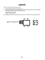
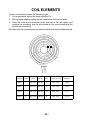
1
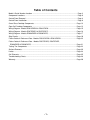
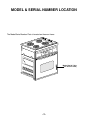
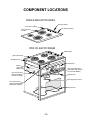
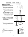
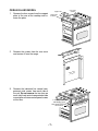
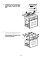
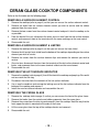
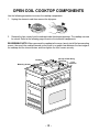
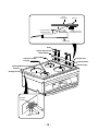
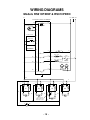
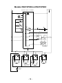
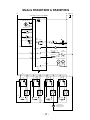
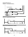
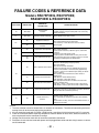
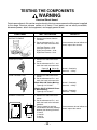
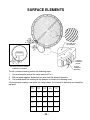
VISION II DROP-IN RANGE
MODELS RS610PXE, RS675PXE, & RS696PXE
JOB AID
Part No. 4322212
FORWARD
This Job Aid will introduce the technician to the Vision II Drop-In Range. This Job Aid
is a reference guide for the experienced technician. It is not designed as a replacement
to basic training. This Job Aid does not replace the Service Manual or the Use and Care
Guide. It is designed to be used in conjunction with these manuals.
OBJECTIVE
The objective of this Job Aid is to have the experienced appliance technician become
familiar with the operation and service of the Vision II Drop-In Range. It is designed as
reference material and is not a replacement for basic training.
WHIRLPOOL CORPORATION assumes no responsibility for any repair made on
our products by anyone other than Authorized Factory Service Technicians.
Copyright 1997 Whirlpool Corporation
WARNING LABELS
This Job Aid is intended for factory-service technicians only. We recommend that customers DO NOT
service their own units, because of the complexity and risk of high-voltage electrical shock.
WARNING
WARNING
Fire Hazard
Do not obstruct the flow of combustion and
ventilation air.
Electrical Shock Hazard
It is the customer’s responsibility to.
• Contact a qualified electrical installer.
• Assure that electrical installation is adequate
and in conformance with the National Electrical Code, ANSI/NFPA 70—latest edition•,
and all local codes and ordinances.
• Take special care when drilling holes into the
wall for venting or electrical wiring. Electrical
wires may be concealed behind the wall covering.
• Disconnect the power to any electrical circuits
that could be affected by the installation of this
cooktop.
Failure to do so could result in fire, electrical
shock, or other personal injury.
Personal Injury Hazard
To eliminate the risk of burns or fires, do not
install cabinets or store things above the cooktop.
If cabinets are already installed above the
cooktop, install a range hood to the bottom of the
cabinet to prevent reaching over the heated
cooking surface. The range hood should stick
out a minimum of 5-inches (12.7 cm) from the
front of the cabinets.
Reaching over a heated cooking surface could
result in a serious burn or other inury.
• Copies of the standards listed above may be
obtained from:
National Fire Protection Association
Batterymarch Park
Quincy, Massachusetts 02269
Electrical Shock Hazard
Electrical ground is required on this range.
Do not connect to the electrical supply until the
range is permanently grounded.
Disconnect power to the junction box before
making the electrical connection.
This range must be connected to a grounded,
metallic, permanent wiring system.
Failure to follow these instructions could result in
death or serious injury.
Electrical Shock Hazard
Disconnect the range’s line cord plug from the wall receptacle before you service
any of the components inside the unit. Failure to do this could result in violent
electrical shock.
VOLTAGE CHECKS
When making voltage checks, be sure to observe the following precautions:
1. The floor must be dry. Water and dampness increase the chances of
electrical shock.
2. Set the voltmeter correctly for the voltage being measured.
3. Touch only the insulated parts of the meter probes.
4. Touch the component terminals, or wires, with the meter probe tips
only.
5. Touch the meter probe tips only on the terminals being checked.
Touching other components could damage good parts.
PARTS QUALITY
An important step in the appliance repair procedure is the selection of FSP®
(FACTORY SPECIFICATION PARTS) as replacements. Use of “fits-all,” or “look alike”
parts could result in early parts failure, safety hazard, or substandard performance
of a WHIRLPOOL appliance. It could also result in an unnecessary repeat of your
repair efforts.
To be sure that the part(s) you purchase meet the exacting quality standards used to
build every new WHIRLPOOL appliance, be sure to ask for genuine FSP replacement
parts, as specified for your model. “FSP” is a registered trademark of WHIRLPOOL
CORPORATION.
You can buy your genuine FSP replacement parts from any authorized WHIRLPOOL
Parts Distributor.
WHIRLPOOL CORPORATION assumes no responsibility for
any repair made on our products by anyone other than qualified
TECH-CARE® Service Technicians.
Copyright 1997 Whirlpool Corporation, Benton Harbor, MI
Table of Contents
Model & Serial Number Location .................................................................................................... Page 2
Component Locations ..................................................................................................................... Page 3
Control Panel Removal ................................................................................................................... Page 4
Control Panel Installation ................................................................................................................ Page 9
Ceran Glass Cooktop Components .............................................................................................. Page 10
Open Coil Cooktop Components .................................................................................................. Page 12
Wiring Diagram - Models RS610PXEW & RS610PXEN .............................................................. Page 15
Wiring Diagram - Models RS675PXEQ & RS675PXEZ ............................................................... Page 16
Wiring Diagram - Models RS696PXEB & RS696PXEQ ............................................................... Page 17
Strip Circuits ..................................................................................................................................Page 18
Failure Codes & Reference Data - Models RS610PXEW & RS610PXEN ................................... Page 20
Failure Codes & Reference Data - Models RS675PXEQ, RS675PXEZ,
RS696PXEB & RS696PXEQ ..................................................................................................... Page 21
Testing The Components .............................................................................................................. Page 22
Surface Elements ..........................................................................................................................Page 23
Limiter ........................................................................................................................................... Page 24
Coil Elements ................................................................................................................................Page 25
Troubleshooting Charts ................................................................................................................. Page 26
Warranty ....................................................................................................................................... Page 28
-1-
MODEL & SERIAL NUMBER LOCATION
The Model/Serial Number Plate is located on the oven frame.
Model/Serial Plate
(On Oven Frame)
-2-
COMPONENT LOCATIONS
CERAN GLASS ELECTRIC RANGES
Element Control
Ceran Glass Cooktop
Hot Surface Indicator
Surface Element
& Limiter
OPEN COIL ELECTRIC RANGES
Indicator Light
Open Coil Element
Cooktop Hi Limit
Control Panel
Blower
(Self-Clean
Models Only)
Door Latch Mechanism
(Solenoid & Door Switches
On Self-Clean Models)
Oven Thermal Fuse
(Self-Clean Models
On Back Of Range)
Broil Element
Oven Temperature Sensor
Oven Thermal Fuse
(Non Self-Clean Models
Underneath Cooktop)
Bake Element
-3-
CONTROL PANEL REMOVAL
REMOVING THE RANGE
small end of pin here
To remove the range from the cabinet, use the
following procedure.
1.
Remove the oven door from the range.
NOTE: This step is optional, but can make
servicing the control panel easier. To remove the door:
a) Open the oven door and insert a
pin, or screw, into each of the hinge
hangers on the sides of the oven
door.
b) Close the oven door as far as the
pins will allow.
c) Grasp the oven door by the handle
and at the bottom, then lift and pull
it up and away from the oven.
2.
Remove the two screws from each side
trim and remove them from the range.
NOTE: Gently tilt trim outward from the
bottom and pull down.
3.
Remove the two screws from the bottom
trim, then pull the trim forward, and remove
it from the range.
Bottom Trim
Bottom Trim Screw
4.
5.
Remove the two screws from the front of
the range that are securing it to the cabinet
front.
Pull the range out far enough to access the
back.
Side Support
Notch
NOTE: If you are servicing a Ceran Glass
Model Cooktop, proceed to page 7.
Wall Mounting Screws
-4-
OPEN COIL MODEL
1.
Remove the screws from the rear cover
and remove it from the range.
Do Not remove the control compartment
back and back cover.
ver
r Co s
a
e
R crew
(8) S
ack
ent B
par tm
m
o
trol C Screws)
Con
(4
r
Cove
Back rews)
c
(11 S
2.
Remove the indicated three control compartment side screws from each side of
the unit. Do not remove the two (one on
each side) front control compartment side
screws/pins or the two control panel screws
at this time.
3 Control Compartment
Side Mounting Screws
Front Control Compartment
Side Screw/Pin
-5-
2 Co
n
anel
trol P
ws
Scre
3.
4.
From the back of the unit, grip the sides of
the cooktop assembly, and separate it
from the control panel. IMPORTANT REMOVAL INSTRUCTIONS: To access the
control panel, it will be necessary to slide
the cooktop assembly back away from the
panel. This may be a bit difficult to do
because the top lip of the control panel is
“friction-fit” in the slot of the cooktop, which
holds it firmly in place. To remove the
cooktop assembly for servicing:
a) From the back of the range, grip the
sides of the cooktop and pull back
firmly, (do not lift up), rocking it
from side-to-side, until the friction
fit releases the cooktop from the
control panel trim extension.
b) Slide the cooktop back far enough
to access the control panel.
CooktopTrim Control Panel
Extension
Trim Extension
Clamp/Support Holds Top
Of Control Panel In Place
At Center Of Cooktop
To remove the control panel, remove the
two front control compartment side screws/
pins and the two control panel screws,
then tilt the panel out at the bottom, and lift
it up and off the side rails.
Front Control Compartment
Side Screw/Pin
rews
el Sc
Pan
ntrol
2 Co
-6-
CERAN GLASS MODEL
1.
Remove the four screws from the support
plate at the rear of the cooktop and remove the plate.
2.
Remove the screws from the rear cover
and remove it from the range.
Ceran Glass
Cooktop
Support Plate
Slotted Holes
At Bottom
ver
r Co
Rea crews
(8) S
ack
ent B
par tm
m
o
trol C Screws)
Con
(4
r
Cove
Back rews)
c
(11 S
3.
Remove the indicated five control compartment side screws from each side of
the unit. Do not remove the two (one on
each side) front control compartment side
screws/pins or the two control panel screws
at this time.
5 Control Compartment
Side Mounting Screws
Front Control Compartment
Side Screw/Pin
-7-
2C
el
l Pan
ontro
ws
Scre
4.
From the back of the unit, grip the sides of
the cooktop, lift it, then slide the cooktop
back far enough to access the control
panel.
Cooktop Trim Control Panel
Trim Extension
Extension
Clamp/Support Holds Top
Of Control Panel In Place
At Center Of Cooktop
Clamp/Support
Lift & Pull Back
5.
To remove the control panel, remove the
two front control compartment side screws/
pins and the two control panel screws,
then tilt the panel out at the bottom, and lift
it up and off the side rails.
Front Control Compartment
Side Screw/Pin
n
anel
trol P
2 Co
-8-
ws
Scre
CONTROL PANEL INSTALLATION
1.
Control Panel
1. Hook Panel
Over Top Of Support
To install the control panel, hook the sides
over the top of the side support, then raise
up on the air deflector and rotate the
bottom of the control panel in so that the
tabs on the control panel slide under the
tabs on the air deflector. Install the two
control panel screws and the two front
control compartment side screws/pins.
Side Support
Air Deflector Tab
Control Panel Tab
2. Lift Air Deflector So Tab On Control
Panel Fits Under Tab On Deflector
Control Panel
Control
Compartment
Side
This Screw Acts As
Pin In Both Sides Of
Control Panel
Cooktop Trim
Extension
NOTE: When you reinstall the ceran cooktop,
position the support bracket tabs to the inside
of the control compartment sides.
2.
3.
Push the cooktop forward so the clamp/
support engages in the control panel, and
loosely install the control compartment
side screws (three on each side of the
open coil cooktop and four on each side of
the ceran cooktop). Push forward on the
cooktop so that it is tightly against the trim
extension (no gap), and tighten the screws.
Reassemble the rest of the range. NOTE:
Make sure that you position the tabs on
the rear cover to the outside of the control
compartment side when you install it.
On Ceran Glass Cooktops
Position Support Bracket
Tab Inside Heat Shield
On Both Sides
Control Panel
Trim Extension
Clamp/Support Holds Top
Of Control Panel In Place
At Center Of Cooktop
Control Panel
Tab Outside
Control
Compartment
Side
-9-
This Screw Acts As
Pin In Both Sides Of
Control Panel
CERAN GLASS COOKTOP COMPONENTS
Refer to the illustration on the following page.
REMOVING A SURFACE ELEMENT CONTROL
1.
2.
3.
4.
5.
Remove the cooktop (refer to page 4) so that you can access the surface element control.
Remove the knob from the surface element control you wish to service and the rubber
grommet from the ceran glass.
Remove the two screws from the surface element control and push it into the cooktop as far
as possible.
From the back of the unit, disconnect the wires one at a time from the old surface element
control, and reconnect them to the terminals with the same markings on the new control.
Reassemble the unit.
REMOVING A SURFACE ELEMENT & LIMITER
1.
2.
3.
4.
5.
Remove the cooktop (refer to page 4) so that you can access the heat shield.
Remove the left or right heat shield from the bottom of the cooktop, depending on the surface
element you wish to service.
Remove the screws from the surface element clips and remove the element you wish to
service.
One at a time, disconnect the wires from the terminals of the old surface element control and
limiter, and reconnect them to the same terminal callouts on the new element.
Reassemble the unit.
REMOVING THE HOT SURFACE INDICATOR
1.
2.
3.
4.
Remove the cooktop (refer to page 4), then lift the front of the cooktop and prop it up. Be careful
not to scratch the trim ring.
Disconnect the wires from the terminals of the hot surface indicator.
Use a small screwdriver and unsnap the locking arms of the hot surface indicator from the
bottom of the cooktop and remove it.
Install the new hot surface indicator and reassemble the unit.
REMOVING THE CERAN GLASS
1.
2.
3.
4.
5.
Remove the cooktop (refer to page 4) so that you can access the front of the glass frame.
Remove the knobs from the controls and rubber grommets from the ceran glass.
Remove the screws from the trim ring and remove it from the cooktop. Note the way that the
front support bracket is mounted to the ends of the frame.
Lift the ceran glass from the top of the cooktop chassis and remove it.
Reassemble the unit.
- 10 -
Frame Screw
Trim Ring
Support Bracket
Support Bracket
Knob
Rubber
Grommet
Ceran Glass
Surface Element Control
Surface Element
Limiter
Hot Surface Indicator
Backer Plate
Heat Shield
Heat Shield
- 11 -
OPEN COIL COOKTOP COMPONENTS
Use the following procedure to access the cooktop components:
1.
Unplug the elements and then remove the drip pans.
2.
Remove the four screws from the cooktop inside the element openings. The cooktop can now
be raised. Refer to the following page to service the individual components.
REASSEMBLY NOTE: When you mount the cooktop to the range, loosely install the four mounting
screws, then push the cooktop forward so that there is no gap or bow between the front edge of
the cooktop and the trim extension, and then tighten the four screws securely.
No Gap or Bow Along
This Edge
Trim
Extension
Cooktop
Mounting Screws
- 12 -
Refer to the illustration on the following page.
REMOVING AN ELEMENT CONTROL
1.
2.
3.
4.
5.
Remove the knob and two mounting screws from the element control you wish to service.
Remove the four mounting screws from the cooktop.
Lift the cooktop and prop it up (be careful not to scratch the countertop or cooktop).
Remove the old element control, then one at a time, disconnect the wires from the terminals,
and reconnect them to the same terminal callouts on the new control.
Reassemble the unit.
REMOVING AN INDICATOR LIGHT
1.
2.
3.
4.
Remove the cooktop and prop it up (be careful not to scratch the countertop).
Slide the old indicator light off the red lens, then one at a time, disconnect the wires from the
terminals of the element controls, and reconnect the wires from the new indicator light to the
same terminals on the controls.
Slide the new indicator light onto the red lens.
Reassemble the unit.
REMOVING THE COOKTOP HI LIMIT
1.
2.
3.
4.
Remove the cooktop and prop it up (be careful not to scratch the countertop or cooktop).
Disconnect the two wires from the terminals of the cooktop hi limit.
Remove the two screws from the cooktop hi limit and remove it.
Reassemble the unit.
REMOVING THE COOKTOP
1.
2.
3.
4.
5.
Remove the knobs and the screws from the four element controls.
Remove the screw from the four element connector sockets and unhook them from the
cooktop.
Remove the green ground wire screw from the right rear burner opening.
Unclip the indicator light from the red lens and remove the lens and control panel from the
cooktop.
Remove the cooktop from the range.
- 13 -
Top Of
Control Panel
Press Arms Against
Bottom Of Panel
Red Lens
Slide Arms On Light
Over Shoulder Of Lens
Indicator Light
Knob
Infinite Switch Screw
Infinite Switch
Ground Wire
Connector Socket
& Screw
Indicator Lens
Control Panel
Indicator Light
Cooktop Mounting Screw
Cooktop
Cooktop Hi Limit
COOKTOP
HI LIMIT
CONNECTOR
SCREW
- 14 -
WIRING DIAGRAMS
Models RS610PXEW & RS610PXEN
L1
N GND L2
ELECTRONIC CONTROL - WP #4448874
BK
P5-2
OVEN TEMP SENSOR
V
V
V
V
P3-8
P5-1
W
P4-1
GY
TRANSFORMER
P3-9
+5V SWITCH PULSE
P3-6
DOOR SWITCH
TAN
BR
P3-5
Y
P3-1
RETURN LINE MUST
BE CONNECTED
P3-4
4
1-N
W
M
BLOWER
BAKE - 2000W
P2-4
R/W
R
OVEN
THERMAL FUSE
P2-3
BK
R
BROIL - 3400W
P2-1
OR
OR/W
OPENS @
150˚C/302˚F
P2-2
BK
15W BULB INCANDESCENT
P4-3
BK
BK
BK
W
W
P2-1
P3-7
GN
BK
R
L1
L2
L1
P
L2
L1
P
L2
L1
P
RF
LF
L2
P
LR
RR
H1
H1
BU
H2
OR
H1
OR
H2
Y
H2
BU
2100 W
46 Ω
27 Ω
H2
BU
BU
1250 W
COOKTOP HI LIMIT
OPENS @ 188˚C/370˚F
CLOSES @ 171˚C/340˚F
BU
BU
BR
BR
2100 W
BU
SURFACE INDICATOR LIGHT
R
H1
Y
BU
- 15 -
27 Ω
1250 W
46 Ω
Models RS675PXEQ & RS675PXEZ
L1
N GND L2
ELECTRONIC CONTROL - WP #4448874
BK
P5-2
OVEN TEMP SENSOR
V
V
V
V
P3-8
W
P5-1
TRANSFORMER
P3-9
+5V SWITCH PULSE
P3-6
DOOR SWITCH
TAN
TAN
TAN BR
P3-5
LATCH SWITCH OPERATED
BY SOLENOID
TAN BR
BU BU
P3-3
CAVITY SIZE SELECT
TAN
Y
P3-1
PULSE
RELAY
NC
NO
OR
LOCK
PK
P4-2
TAN
TAN Y
TAN
UNLOCK
Y
W
DOOR SW 2
P3-2
DOOR LOCK SOLENOID
P3-4
P4-1
4
GY
RETURN LINE MUST BE CONNECTED
1-N
W
M
BLOWER
BAKE - 2000W
P2-4
BK
R/W
R
OVEN
THERMAL FUSE
P2-3
R
BROIL - 3400W
P2-1
OR
OR/W
OPENS @
150˚C/302˚F
P2-2
BK
15W BULB INCANDESCENT
P4-3
BK
BK
W
W
P3-7
GN
BK
R
L1
L1
L2
L2
L1
P
P
L2
L1
P
LF
L2
P
RF
LR
RR
H1
R
BU
H1
H2
OR
OR
BU
1500 W
H1
H2
Y
Y
H2
BU
2600 W
BR
BR
38 Ω
22 Ω
COOKTOP HI LIMIT
OPENS @ 188˚C/370˚F
CLOSES @ 171˚C/340˚F
BU
2600 W
BU
SURFACE
INDICATOR
LIGHT
R
- 16 -
BU
22 Ω
H2
H1
BU
BU
1500 W
38 Ω
Models RS696PXEB & RS696PXEQ
L1
N GND L2
ELECTRONIC CONTROL - WP #4448874
BK
P5-2
OVEN TEMP SENSOR
V
V
V
V
P3-8
W
P5-1
TRANSFORMER
P3-9
+5V SWITCH PULSE
P3-6
DOOR SWITCH
TAN
TAN
TAN BR
P3-5
LATCH SWITCH OPERATED
BY SOLENOID
TAN
BR
BU BU
P3-3
CAVITY SIZE SELECT
TAN
Y
P3-1
PULSE
RELAY
NC
P3-2
NO
OR
LOCK
PK
P4-2
TAN
UNLOCK
TAN Y
Y
W
DOOR SW 2
DOOR LOCK SOLENOID
TAN
P3-4
P4-1
4
GY
RETURN LINE MUST BE CONNECTED
1-N
W
M
BLOWER
BAKE - 2000W
P2-4
BK
OVEN
THERMAL FUSE
R/W
R
P2-3
R
BROIL - 3400W
P2-1
OR
OR/W
OPENS @
150˚C/302˚F
P2-2
BK
15W BULB INCANDESCENT
P4-3
BK
BK
W
W
P3-7
GN
BK
R
L1
LF
L1
L2
P
LR
L2
L1
H1
H2
OR
OR
L2
H1
Y
H2
BR
H1
2600 W
2600 W
38 Ω
22 Ω
22 Ω
H2
BU
BR
1500 W
BU
L2
P
H2
Y
RR
L1
P
P
H1
RF
BU
1500 W
38 Ω
HOT SURFACE
INDICATOR & ELEMENT
ON INDICATOR LIGHT
R
- 17 -
STRIP CIRCUITS
BAKE & PREHEAT - BAKE
L1
L2
N
ELECTRONIC OVEN CONTROL
BK
P2-4
R
BAKE - 2000W
R/W
P2-3
R
OR/W
OR
BK
BROIL - 3000W
OR/W
P2-1
P2-2
BLOWER
GY
4
P4-1
BK
M
W
1
P3-2
BROIL
L1
L2
N
ELECTRONIC OVEN CONTROL
BK
P2-1
OR
BROIL - 3000W
R
OR/W
P2-2
P4-1
BK
GY
P5-2
- 18 -
BLOWER
1
4
M
W
CLEAN (ABOVE 600˚F) &
PREHEAT - CLEAN (BELOW 600˚F)
L1
N
L2
ELECTRONIC OVEN CONTROL
DOOR
SW 2
LOCK RELAY
PULSE
RELAY
PNK
P4-2
TAN
TAN
Y
Y
BK
W
DOOR LOCK
SOLENOID
UNLOCK RELAY
BK
W
P4-1
GY
4
BLOWER
1
M
W
P5-2
P2-4
R
BAKE - 2000W
R/W
P2-3
R
BK
P2-1
OR
BROIL - 3000W
OR/W
P2-2
OPEN COIL SURFACE UNIT (TYPICAL)
L1
L2
INFINITE SWITCH
SURFACE ELEMENT
INDICATOR
P
BK
BU
R
INFINITE SWITCH
L1
SURFACE ELEMENT
H1
H2
L2
R
CERAN GLASS SURFACE UNIT (TYPICAL)
L1
L2
CLOSES @ 275˚F
2B
1B
INFINITE SWITCH
HOT SURFACE& ELEMENT
ON INDICATOR
P
BK
V
R
INFINITE SWITCH
L1
OPENS @ 1075˚F
H1
SURFACE ELEMENT
- 19 -
1A
2A
H2
L2
R
FAILURE CODES & REFERENCE DATA
Models RS610PXEW & RS610PXEN
FAULT CODE
ERROR CODE
MEANING OF
FAILURE CODE
REPAIR PROCEDURE
- F0 -
All E-Codes
Default F-Code
no failure.
Will only be displayed if user presses and holds Cancel key
for 5-seconds and there is no pre-existing fault. Press
Cancel key again to clear display.
- F1 -
All E-Codes
Electronic control malfunction.
- E0 -
Keypad not connected.
- E2 -
Key held down too long or key
is shorted.
- E0 -
Temperature sensor opened.
- E1 -
Temperature sensor shorted.
- E2 - E3 -
Oven temperature too high.
- E0 -
Return line not connected.
- F2 -
- F3 -
- F6 -
Replace control if the E-Code is not E3.
Check keypad connector for firm connection.
Press Cancel key. If error code returns after 60-seconds,
replace keypad.
Check sensor connection.
Measure sensor resistance (1080 ohms @ 70˚F; add 2
ohms per degree).
If resistance is not valid, replace sensor.
If sensor resistance and connections are okay, then the
oven cavity temperature must have exceeded a safe level.
Check for relay contacts welded together on control board.
If switch pulse return line is not connected, electronic
control will display F6 within 60-seconds after power-up.
NOTES:
1. The most common cause for control failure is corrosion on connectors. Therefore, disconnecting and reconnecting wires will be necessary during test procedures.
2. All tests should be made with a VOM or a DVM having a sensitivity of 20,000 ohms per volt DC, or greater.
3. Check all connections before replacing components. Look for broken or loose wires, defective terminals, or
wires not pressed into the connector far enough.
4. Voltage checks must be made with all connectors attached to the boards.
5. Resistance checks must be made with power cord unplugged from outlet and with wiring harness or connectors disconnected.
- 20 -
FAILURE CODES & REFERENCE DATA
Models RS675PXEQ, RS675PXEZ,
RS696PXEB & RS696PXEQ
FAULT CODE
ERROR CODE
MEANING OF
FAILURE CODE
- F0 -
All E-Codes
Default F-Code
no failure.
- F1 -
All E-Codes
Electronic control malfunction.
- E0 -
Keypad not connected.
- E2 -
Key held down too long or key
is shorted.
- E0 -
Temperature sensor opened.
- E1 -
Temperature sensor shorted.
- E2 - E3 -
Oven temperature too high.
REPAIR PROCEDURE
Will only be displayed if user presses and holds Cancel key for
5-seconds and there is no pre-existing fault. Press Cancel key
again to clear display.
- F2 -
- F3 -
- E0 -
- F5 - E1 -
- E2 -
- F6 -
- F7 -
- E0 -
- E0 -
Replace control if the E-Code is not E3.
Check keypad connector for firm connection.
Press Cancel key. If error code returns after 60-seconds,
replace keypad.
Check sensor connection.
Measure sensor resistance (1080 ohms @ 70˚F; add 2 ohms
per degree).
If resistance is not valid, replace sensor.
If sensor resistance and connections are okay, then the oven
cavity temperature must have exceeded a safe level. Check for
relay contacts welded together on control board.
Check the latch assembly ( latch arm pivot joint, arm solenoid
connection, solenoid spring and spring washer).
Check latch solenoid.
Door is open but latch is locked. Check for firm electrical connections.
Disconnect the two wires from the solenoid and measure the
resistance of the solenoid. A small resistance (approximately
175 ohms) is normal. If the solenoid is open (infinity) or shorted
(0 ohms), replace it.
Check the latch switch. Disconnect the switch and use a
continuity tester:
Self-clean latch will not lock.
Door latched = switch closed (0 ohms).
Door unlatched = switch open (infinity).
Check door open/closed switch. Disconnect the switch wires
and use a continuity tester:
Self-clean latch will not unlock.
Door open = switch (1) closed circuit, switch 2 (open circuit).
Door closed = switch (1) open circuit, switch 2 (closed circuit).
Return line not connected.
If switch pulse return line is not connected, electronic control will
display F6 within 60-seconds after power-up.
Common switch wire is
defective.
Common wire (+5VDC) to latch switch and to door switch is
shorted to chassis ground or neutral.
Check connections at control and at the latch switch and door
switch.
If all connections are okay, then check the individual switches as
outlined for the F5 failure.
NOTES:
1. The most common cause for control failure is corrosion on connectors. Therefore, disconnecting and reconnecting wires will be necessary during test procedures.
2. All tests should be made with a VOM or a DVM having a sensitivity of 20,000 ohms per volt DC, or greater.
3. Check all connections before replacing components. Look for broken or loose wires, defective terminals, or
wires not pressed into the connector far enough.
4. Voltage checks must be made with all connectors attached to the boards.
5. Resistance checks must be made with power cord unplugged from outlet and with wiring harness or connectors disconnected.
- 21 -
TESTING THE COMPONENTS
WARNING
Electrical Shock Hazard
Certain procedures in this section require electrical tests or measurements while power is applied
to the range. Exercise extreme caution at all times. If test points are not easily accessible,
disconnect power, attach test equipment, and reapply power to test.
COMPONENT
TEST PROCEDURE
1. Remove the element from the
connector.
2. Set the ohmmeter to R x 1 and
touch the leads to the terminals.
Left Front Element = 38 Ω.
Left Rear Element = 22 Ω.
Right Front Element = 22 Ω.
Right Rear Element = 38 Ω.
SURFACE ELEMENT
COOKTOP HI LIMIT
OVEN THERMAL FUSE
ELEMENT CONTROL
L2
L1
P
H1
If measurements do not indicate as
shown, replace the element.
1. Remove the leads from the terminals.
2. Set the ohmmeter to R x 1 and
touch the leads to the terminals.
Opens @
H2 L2 L1
RESULTS
P
H1
H2
Element
Closes @
188˚C/370˚F 171˚C/340˚F
Normal = Continuity.
Abnormal = Infinity.
1. Remove the leads from the terminals.
2. Set the ohmmeter to R x 1 and
touch the leads to the terminals.
Model RS610 W/Yellow Marking:
Opens @ 120˚C/248˚F
Normal = Continuity.
Abnormal = Infinity.
Models RS675 & RS696 W/Green
& White Marking:
Opens @ 150˚C/302˚F
Normal = Continuity.
Abnormal = Infinity.
1. Remove the leads from the terminals.
2. Set the ohmmeter to R x 1 and
touch the leads to the indicated
terminals.
3. Turn the control on and you
should obtain continuity readings
between the following terminals:
L1 and P
L1 and H1
P and H1
L2 and H2
- 22 -
If measurements do not indicate as
shown, replace the control.
SURFACE ELEMENTS
BOTTOM SIDE
OF ELEMENT
SINGLE
TERMINAL
(OPEN)
SINGLE
TERMINAL
(BARRED)
BOTTOM VIEW OF ELEMENT
SCHEMATIC DIAGRAM
To test a surface element, perform the following steps:
1. Use an ohmmeter and set the range switch to R x 1.
2. With no power applied, disconnect one wire from the element terminals.
3. You should obtain the reading for the element as listed in the following chart.
If the resistance reading is not within the range shown, the element is defective and should be
replaced.
Whirlpool
Part No.
Wattage
Rating
Voltage
Rating
Total
Wattage
Resistance
(Cold)
3189894
1400
240 VAC
1400 ±5%
40 Ω ±5
3189895
1700
240 VAC
1700 ±5%
27 Ω ±5
3189896
2100
240 VAC
2100 ±5%
22 Ω ±5
3189897
2400
240 VAC
2400 ±5%
17 Ω ±5
- 23 -
LIMITER
To test a limiter, perform the following steps:
1. Use an ohmmeter and set the range to R x 1.
2. With no power applied, touch the ohmmeter leads to the following terminals. You should obtain
the following readings at the indicated temperature:
1A and 2A opens @ 1025˚F
1B and 2B closes @ 275˚F
If the readings are not within the range shown, the limiter is defective and should be replaced.
- 24 -
2A
2B
1A
1B
2A
2B
1A
1B
COIL ELEMENTS
To test a coil element, perform the following steps:
1. Use an ohmmeter and set the range switch to R x 1.
2. With no power applied, unplug the coil element from the terminal block.
3. Touch the leads of the ohmmeter to the terminals of the coil element and
measure the resistance (see the chart below for the correct reading for the
element you are testing).
If the above results are not obtained, the element is defective and should be replaced.
Whirlpool
Part No.
Number
of Turns
Wattage
(Nom.)
Voltage
208/240
Element
Hot Watts
Size
@ 240V –10% +5%
660529
4
940 / 1250
208 / 240
6"
1125 - 1312
42 - 50
660532
4
1130 / 1500
208 / 240
6"
1350 - 1575
35 - 41
660531
5
1580 / 2100
208 / 240
8"
1890 - 2205
25 - 30
660533
5
1950 / 2600
208 / 240
8"
2340 - 2730
20 - 24
- 25 -
Cold Ohms
Resistance
TROUBLESHOOTING CHARTS
WARNING
Electrical Shock Hazard
Certain procedures in this section require electrical tests or measurements while power is applied
to the range. Exercise extreme caution at all times. If test points are not easily accessible,
disconnect power, attach test equipment, and reapply power to test.
PROBLEM
POSSIBLE CAUSE
SOLUTION
Clock display does not display 4
number eights after power-on
test.
Loose or bad wiring.
Check wiring (see wiring diagrams).
Burned out or missing segment in
clock display.
Broken or missing terminal on
microcomputer.
Make sure clock display is properly seated.
Check microcomputer board.
Oven cooks but display does not
count down in cooking cycle.
Loose or bad wiring to harness.
Failed microcomputer board.
Check wiring (see wiring diagrams).
Check microcomputer board.
Oven element emits black smoke
when first turned on.
This is normal on a new range.
The factory-applied protective
coating is burning off.
Substance (e.g. food or other material) has spilled onto the element.
Protective coating will burn off in
several minutes. Fumes are nontoxic.
Let element cool then clean according to Use & Care instructions.
Oven element does not heat.
No line voltage.
Loose or bad wiring.
Check circuit breaker.
Check wiring (see wiring diagrams).
Check element.
Defective element.
Cooktop element barely heats.
Low line voltage.
Loose or bad wiring connection at
element or terminal block.
Defective cooktop control switch.
- 26 -
Line voltage should be minimum
240-volts. If necessary, electrician should repair cause for low
line voltage.
Check wiring (see wiring diagrams).
Check switch.
PROBLEM
POSSIBLE CAUSE
SOLUTION
Cooktop element will not heat
higher than low-medium.
Low line voltage.
Defective cooktop element.
Line voltage should be minimum
240-volts. Electrician should repair cause for low line voltage.
Check element.
Cooktop element heats up normally, but drops to lower setting
automatically.
Customer using improper cookware.
Defective cooktop control switch.
Evaluate suitability of cookware.
Check switch.
Indicator light does not light up.
Loose or bad wiring to indicator
light.
Defective indicator light.
Defective cooktop control switch.
Check wiring (see wiring diagrams).
Check indicator light.
Check switch.
Hot surface indicator light does
not work.
Loose or defective light.
Loose or bad wiring to indicator
light assembly.
Check indicator light.
Check indicator light assembly
and wiring.
Oven light fails to operate.
Bulb burned out.
Circuit breaker or fuse is open.
Check bulb.
Check circuit breaker or replace
fuse.
Check continuity and/or replace
switch.
Defective switch.
Door locks but indicator lights do
not light. Oven does not begin
clean cycle.
Defective indicator light.
Defective latch safety switch.
Check indicator light.
Check switch.
Electronic timer will not accept
programming.
Failed electronic board.
Replace timer.
Timer relay(s) do not close.
Loose or bad wiring to timer.
Check wiring (see wiring diagrams).
Replace timer.
Failed electronic board.
Oven will not bake (selection is
set for BAKE).
If indicator light lights up bake
element is defective.
Defective latch safety switch.
Loose or bad wiring.
Oven will not bake (selection is
set for TIMED BAKE).
Defective electronic clock.
- 27 -
Check and/or replace bake element.
Check continuity and/or replace
switch.
Check wiring (see wiring diagrams).
Check continuity and/or replace
clock (see wiring diagrams).
WARRANTY
Whirlpool ® Drop-In Range
LENGTH OF WARRANTY
WHIRLPOOL WILL PAY FOR:
FULL ONE YEAR WARRANTY
From Date of Purchase.
FSP® replacement parts and repair labor to correct defects in materials or workmanship. Service must be provided by an authorized
Whirlpool service company.
WHIRLPOOL WILL NOT PAY FOR:
A. Service calls to:
1.
2.
3.
4.
Correct the installation of the range.
Instruct you how to use the range.
Replace house fuses or correct house wiring or plumbing.
Replace owner-accessible light bulbs.
B. Repairs when range is used in other than normal, single family household use.
C. Pickup and delivery. Your range is designed to be repaired in the home.
D. Damage to your range caused by accident, misuse, fire, flood, acts of God, or use of products not approved by Whirlpool.
E. Repairs to parts or systems caused by unauthorized modifications made to the appliance.
WHIRLPOOL SHALL NOT BE LIABLE FOR INCIDENTAL OR CONSEQUENTIAL DAMAGES. Some states do not allow the
exclusion or limitation of incidental or consequential damages, so this exclusion or limitation may not apply to you. This warranty
gives you special legal rights, and you may also have other rights which vary from state-to-state.
Outside the United States, a different warranty may apply. For details, please contact your authorized Whirlpool distributor or
military exchange.
If you need service first see the “Troubleshooting” section of the Use and Care Guide. After checking ”Troubleshooting,” additional
help can be found by checking the “Requesting Assistance or Service” section, or by calling our Consumer Assistance Center
telephone number from anywhere in the U.S.A.
Whirlpool: 1-800-253-1301 Benton Harbor, Michigan 49022
Canadian Residents call: 1-800-461-5681
® Registered trademark of Whirlpool Corporation
- 28 -