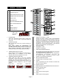
1
S E R V I C E M A N U A L For all Evolution models manufactured from January 2001 Part No. 32Z3382e Issue No. 3 SERVICE MANUAL Evolution CAUTION MICROWAVE EMISSIONS DO NOT BECOME EXPOSED TO EMISSIONS FROM THE MICROWAVE GENERATOR OR PARTS CONDUCTING MICROWAVE ENERGY Page 1 Table of Contents Safety Code ................................................................ 3 Product Specifications ................................................ 4 Dimensions. Location and Installation ........................ 5 Manual RHS controls .................................................. 7 Error Codes and Diagnostics ...................................... 8 Main Features ............................................................ 9 A -Power Output Testing to EN 60335-2-90:1996 ..... 10 B - Power Output Testing.......................................... 11 C - Power Transformer Test ..................................... 11 D - High Voltage Capacitor Test ............................... 12 E - High Voltage Rectifier Test .................................. 12 Principal Components: Right side view ..................... 13 Principal Components: Right side view ..................... 14 Principal Components: Rear view, top view .............. 15 Oven Door Assembly ................................................ 16 Door Interlock Operation ........................................... 17 Error Light Operation ............................................... 17 Input Wiring Details................................................... 18 Control Panel Assembly ............................................ 19 Membrane Panel Circuit............................................ 20 Circuit Diagram ................................................. 21 & 22 Parts Matrix............................................................... 23 Reply Form ............................................................... 24 Merrychef Limited, Station Road West, Ash Vale, Aldershot, Hampshire GU12 5XA,UK. Tel: +44 (0)1252 371000 Fax: +44 (0)1252 371007 Internet address: http://www.merrychef.co.uk E-mail: [email protected] or [email protected] Page 2 SAFETY CODE This manual is designed to assist engineers who have been on a recognised product familiarisation and training course run by Merrychef Limited. It has been prepared to offer technical guidance for the Merrychef Evolution range of Combination Microwave Ovens. Please remember that it is wiser not to attempt a service task if you are unsure of being able to complete it competently, quickly, and above all safely. To avoid injury to yourself, and to protect the appliance from possible damage, please follow this Safety Code when servicing these ovens. Before attempting to repair the oven, check it for microwave leakage. Check that the oven is not emitting microwaves, even when supposedly not in operation. Check that the oven is not operating continuously, whether the display indicates cooking or not. Always discharge the HT capacitors before working on the oven using a suitably insulated 10 MΩ Resistor Before removing the rear cover from the oven, do all of the following: • Switch off the mains supply and remove the plug from the wall socket. or • If the oven is hard wired, ensure that the power is turned off at the isolator switch. Note: The On/Off switch on the oven is not adequate protection against electric shock, as it does not isolate all of the internal wiring from the mains. Upon completion of a service on a Evolution oven, or before reconnecting the appliance to the mains supply for testing, check all of the following points: • • • • • • • • All internal electrical connections are correct. All wiring insulation is correct and is not touching a sharp edge. All Earth connections are electrically and mechanically secure. All four door safety interlocks are secure and mechanically sound. The door operation is smooth, and the arms run freely in the slots. The door activates all four of the door interlock switches in the correct order. All fuse-holder safety covers are correctly fitted. The temperature sensor is correctly connected to the Power PCB. Before finishing the service call, recheck the following points: • • • • • All of the electronics are functioning correctly, and all of the touch pads are working The turntable is rotating freely The power output of the oven is correct Microwave emission is below permissible limit - 5 mW/cm² (see BS EN 60335-2-90:1998) Oven has correct 120 mm air gap all round and 100 mm above. Air flow should not be restricted Page 3 PRODUCT SPECIFICATIONS Model Number: EV + Voltage + Frequency + Phase + Version Model prefix Voltage Frequency EV 24=240V 5 = 50 Hz 6 = 60 Hz Power Requirement Voltage Current Single EV2451B Twin EV2452B Phase Control Type 1 = Single 2 = Twin 3= Three Phase B Microwave Convection Combination 240V 45A 20A 21A 41A P1 240V 25A 20A 1A 20A P2 240V 25A 0 20A 20A Convection Heat Combination 2000 Watts (IEC 705 Rating) Single & Twin supply 1800 Watts (IEC 705 Rating) Three Phase supply 5000 Watts 2000 Watts Microwave + 5000 Watts Convection Heat External Dimensions Height Width Depth 700 mm (Plus 100 mm minimum clearance above 755 mm (Plus 100 mm minimum clearance each side 555 mm (Plus 100 mm clearance behind Internal Dimensions Height Width Depth Turntable Capacity 315 mm 330 mm 330 mm 300 mm Diameter 34.3 litres (1.21 ft³) Weight Net Gross packed 82 kg 90 kg Construction Cavity Casework 304 Stainless Steel 304 Stainless Steel Settings Microwave Temperature Timer 100%,75%,50%,25%, Convection only Off, 150°, 200°, 250°, 275°,300°C Up to 30 minutes (Manual) 3 cooking stages of up to 30 minutes each (Programed) Power Output Microwave 100% Wipe-clean touch pad operating microprocessor based control system Single touch control of temperature Direct readout of time, power and temperature set Digital readout of cavity temperature available 100 Pre-programmed cooking sequences Built-in diagnostic messages Control System Four door interlock switches Cavity Overheat Sensor Magnetron Overheat Sensor Blocked Air Filter Sensor Automatic Lock-out on invalid time setting Convection Fan and Heater disabled when door open Safety Features Additional Features • • • • • • Easy-to-use multistage programming Manual and Pre-programmed mode always available Rapid cavity pre-heat Low-loss insulated cavity and door One-touch selection of temperature Magnetron soft-start circuit for increased life and faster activation Page 4 = 800 ) = 955 ) = 655 ) DIMENSIONS AND LOCATION A sample of this product has been tested and found to be in conformity with the following directives: Directive Harmonised standards applied. EMC 89/336 EEC EN 55011 EN 50082-1 LVD 73/23 EEC EN 60 335-2-90 Page 5 1991 (Emissions) 1992 (Immunity) INSTALLATION INSTRUCTIONS Power Supply Requirements The Evolution should be connected to a suitable electricity supply, which can cope with the switching-on surge that occurs with certain types of catering equipment, such as microwaves. Because of this requirement, we strongly recommend that a separate, suitably rated supply is installed for the oven. The supply for the oven should be fitted with a Type "C" circuit breaker. Please refer to rating plate for details. If the oven is hard wired to the supply a double-pole isolator switch with a contact gap of at least 3mm should be fitted. Positioning the Oven In order to maintain adequate ventilation for air intake and exhaust, and to allow access for cleaning filters, you must allow a minimum of 100 mm clearance at the sides and 100 at the rear of the oven, and at least 100 mm above. Air intake temperature should not exceed 35°C excessive temperature can lead to reduced operating duty cycle or premature ageing of internal components. NEVER Install an oven above fryers, grills, griddles or any other major heat source. NEVER Stack machines on top of each other - always use a double stand. Page 6 MANUAL CONTROLS 1 POWER PADS 2 CONVECTION PAD 3 TIME/PROGRAM SELECT PADS 4 TEMPERATURE SETTING PADS 5 CANCEL PAD 6 PROGRAM PAD 7 TIME AND PROGRAM DISPLAY 8 MULTI-STAGE INDICATOR 9 COLON 10 ON/OFF SWITCH 11 ERROR DISPLAY PHUU\FKHI 7 TIME AND PROGRAM DISPLAY 1. 2. POWER PADS There are 4 Microwave Power Pads to select from: 25%, 50%, 75%, and 100%. A light will indicate the one in use. CONVECTION PAD This is used when foods only require browning( no microwave) Note: when cooking the MICROWAVE and CONVECTION pads start the cycle and timer. You may alter power levels during a manual cooking cycle. When cooking is interrupted, a light will flash as a reminder that the time is being held (see PAUSE). 3. TIME/PROGRAM SELECT PADS These pads are used for setting the cooking time in 1 second steps to a maximum of 30 minutes. They are also used for programs from 21-99. 4. TEMPERATURE SETTING PADS These pads are used to set the convection temperature. A light will indicate the temperature set. Selecting the ‘0’ key will switch convection off. If a temperature key is pressed and held the current oven temperature will be displayed in the time display window. 100C-125ºC below 100ºC above 125ºC 5. CANCEL/ CALLBACK ‘C’ PAD Cancels all timed cooking cycles, pre-programmed operations and stop the microwave energy. It does not alter the oven temperature . If the oven is hot food will continue to cook and should be removed from the oven immediately. This pad will also cancel any incorrect operations. It will not erase programs. It can also be used to view the details of stored programs. (see CALL BACK) 6. PROGRAM ‘P’ PAD Activate or set program 7. TIME AND PROGRAM DISPLAY Shows the time set in minutes and seconds and counts down in 1 second steps during a cooking cycle. Also displays error messages and oven temperature. (PROBLEM SOLVING section 8) The program display indicates the program number selected. ‘PP’ indicates programming 8. MULTI-STAGE INDICATOR Indicates stage in multi-stage cooking 9. COLON When programming the colon will flash to indicate the time may now be entered. 10. ON/OFF SWITCH 11. ERROR DISPLAY See PROBLEM SOLVING Section 8. 12. QUICK ACCESS PADS For programs 01-20 13. START Starts a quick access program 14. STOP Stops a quick access program Page 7 Error Codes and Diagnostics The Evolution will identify some of the most common problems by flashing an error message code in the time display window. (See also Error Light Operation page 17). These are the error messages and suggestions for repairing them. 1 Door not fully shut. Close door fully. 2 Possible electrical fault Door switch inoperative. 1 No time has been set. Set a time. 2 3 Invalid time has been set. Set a valid time. Invalid program has been set. Use call-back to check program. 1 Oven not heating up. Check heater fuse. 2 Possible Heater fault. 3 Possible Sensor fault. Confirm operation of heater circuit. (RS units) Check slave heater relay and second supply. 1 Oven Cavity overheating. Confirm heater relay is operating. (RS units) Check slave heater relay . 1 Oven is not at correct tem- Remove food. perature to start program. Allow oven to reach correct temperature. Operator Error !! 1 Left Hand Magnetron overheating. Check air filters. Check location, air inlet temperature and air filters. Note : this will lead to condition shown below. See Page 18 1 Right Hand Magnetron overheating Check air filters. Check location, air inlet temperature and air filters. Note : this will lead to condition shown below. See Page 18 1 Magnetron has over- Check that magnetron cooling fan heated but has now recov- and turntable are working corered. rectly. Check installation, air inlet temInternal diagnostic fault perature and air filters. See Page 18 2 1 Oven control area is over- Check air filters. heating. Check axial fan. Check installation for hot air intake. Page 8 MAIN FEATURES 1 1 7 2 9 3 8 10 11 4 12 5 13 6 1. TRAY HANDLE REST 6. There is one on each side of the oven for convenient storage of the tray handle. The handle may be used to remove hot trays and the rotating cooking carousel from the oven. 2. AIR OUTLETS These vents on the rear panel enable air which has been used to cool internal components to escape. It will not allow microwave energy to escape into the environment. They must be kept free from obstruction. 3. OVEN CAVITY This is a rigid bar which is pulled downwards and towards you to open 7. GREASE FILTERS (LEFT & RIGHT) 8. MANUAL CONTROLS (See page 11) 9. QUICK ACCESS KEYS 10. ON/OFF SWITCH When switched ON, the control will light. The fan and ventilation system will also operate and the rotating cooking carousel will rotate. 11. The cavity is constructed mainly from stainless steel and vitreous enamelled panel on the door. It must be kept clean Section 7 CLEANING). 4. 13. AIR INLET FILTERS (LEFT & RIGHT) Situated at the left and right hand side of the base at the front. These are part of the ventilation system and must be kept free of obstruction and cleaned on a daily basis. Page 9 DOOR This is a precision-made energy barrier with three microwave safety interlocks. It must be kept clean (see CLEANING section ). The door should NOT be used to support heavy dishes. The cooking carousel disc is placed on the spindle in the centre of the oven floor. The cooking carousel tray fits on top of the disc. These rotate when the oven is switched on and stop when the door is opened. 5. RATING PLATE Found on the rear panel, this states the serial number, model type, electrical specifications and manufacturer’s address and telephone number. 12. COOKING CAROUSEL TRAY AND DISC DOOR HANDLE DOOR SEALS These ensure a tight seal around the door. They should be kept clean and checked regularly for signs of damage. At the first sign of wear they should be replaced by a Merrychef approved engineer. Procedure A - Power Output Test in accordance with BS EN 60335-2-25:1996 Annex AA This test is given in the BSI test standard for microwave ovens. It is reproduced below - not so that you can follow it, but to show you why it is impractical in normal conditions. A simplified procedure, which gives a good approximation to the BSI power output, is given in Procedure B which follows. Note: This test can only be carried out on a COLD oven. If the oven has been operating, even for only a few seconds, the power given will be lower than the oven rating. This test must also be carried out at a stable voltage - the voltage in most kitchens varies considerably even within the period of the test. If the oven has been operating, go to Procedure B. You will need: A thermometer capable of reading to ±0.1°C. A cylindrical borosilicate glass container, 190 mm diameter, with a wall thickness of 3 mm or less. A calculator. A set of scales capable of reading 1 kg to an accuracy of ± 1 g. A glass or plastic stirrer. A jug capable of holding over 1 litre of water. WARNING: The Borosilicate Glass container has thin walls and is therefore fragile - take care not to break it during use. Method: A cylindrical container of borosilicate glass is used for the test. It has a maximum thickness of 3 mm, an external diameter of approximately 190 mm and a height of approximately 90 mm. The mass of the container is determined. At the start of the test, the oven and the empty container are at ambient temperature. Potable water having an initial temperature of 10°C ± 1°C is used for the test. The temperature of the water is measured immediately before it is poured into the container. A quantity of 1000 g ± 5 g of water is added to the container and its actual mass obtained. The container is then immediately placed in the middle of the oven shelf which is in its lowest normal position. The appliance is supplied at rated voltage and operated at the maximum power setting. The time for the water temperature to attain 20°C ± 2°C is measured. The oven is then switched off and the final water temperature is measured within 60s. Notes: 1. The water is stirred before its temperature is measured. 2. Stirring and measuring devices are to have a low heat capacity. The microwave power output is calculated from the formula: 4.187 MW (T2-T1) + 0.55 MC (T2-T0) P= t Where P is the microwave power output, in watts; MW is the mass of the water, in grams; MC is the mass of the container, in grams; T0 is the ambient temperature, in °C; T1 is the initial temperature of the water, in °C; T2 is the final temperature of the water, in °C; t is the heating time in seconds, excluding the magnetron filament heat-up time. Page 10 Procedure B - Simplified Power Test You will need: A thermometer capable of reading to ±0.1°C. A Polypropylene tray approximately 200 mm x 200 mm. A measuring jug. A calculator. Water which is at a temperature of 10°C ± 2°C. 1. 2. 3. 4. 5. 6. 7. 8. Measure 1 litre of cold water into the tray using the measuring jug. Measure the water temperature, and record it as T[s]. Place the tray on the turntable in the oven and close the door. Turn the oven on. Set the timer to 1:02. Press the “100%” pad. When the oven bleeps, open the door and remove the tray. Stir the water thoroughly, and measure its temperature. Record this as T[e]. Calculation: 1. T[r] = T[s] - T[e]. 2. Power = 70 x T[r]. Power is in Watts. The power given by the above test should be within ±10% of the rated power. Procedure C - Power Transformer Test You will need: A Digital Multi-meter (D.M.M.) A Megger or similar resistance meter using 500V d.c. WARNING: High voltages and large currents are present at the secondary winding and filament winding of the Power Transformer. It is very dangerous to work near this part when the oven is on. NEVER make any voltage measurements at the High Voltage circuits, including the magnetron filament. WARNING: Even when the oven is not cooking, the Power Transformer has High Voltages present because of the Soft Start circuit. Isolate the oven before testing. 1. 2. 3. 4. Isolate the oven from the mains supply. Ensure that the High Voltage Capacitor is discharged before commencing work. Remove all connections from the Power Transformer. Using a D.M.M., check the resistance of the windings. Results should be as follows: Mains winding (between tags) Approximately 1.1 Ω High Voltage winding (between tag & chassis) Approximately 60 Ω Less than 1 Ω Filament winding (between terminals) 5. Using a Megger, test the insulation resistance between: Primary winding and chassis Pass if over 10 MΩ Filament winding and chassis Pass if over 10 MΩ One end of the High Voltage winding is connected to the chassis, so this is not tested. Page 11 Procedure D - High Voltage Capacitor Test You will need: A Digital Multi-meter (D.M.M.) A Megger or similar resistance meter using 500V d.c. WARNING: High voltages and large currents are present at the High Voltage Capacitor. It is very dangerous to work near this part when the oven is on. NEVER make any voltage measurements at the High Voltage circuits, including the magnetron filament . WARNING: Even when the oven is not cooking, the High Voltage Capacitor has High Voltages present because of the Soft Start circuit. Isolate the oven before testing. 1. 2. 3. 4. 5. Isolate the oven from the mains supply. Ensure that the High Voltage Capacitor is discharged before commencing work. Remove all connections from the High Voltage Capacitor. Using a D.M.M., check for continuity between the terminals & compare results with table. Using a Megger, test the insulation resistance between the terminals and the case. Between Terminals Pass if approximately 10 MΩ Between Terminals and Case Pass if open circuit Between Terminals and Case Pass if over 100 MΩ Procedure E - High Voltage Rectifier Test You will need: A Megger or similar resistance meter using 500V d.c. WARNING: High voltages and large currents are present at the High Voltage Rectifier. It is very dangerous to work near this part when the oven is on. NEVER make any voltage measurements at the High Voltage circuits, including the magnetron filament . WARNING: Even when the oven is not cooking, the High Voltage Rectifier present because of the Soft Start circuit. Isolate the oven before testing. 1. 2. 3. 4. has High Voltages Isolate the oven from the mains supply. Ensure that the High Voltage Capacitor is discharged before commencing work. Remove all connections from the High Voltage Rectifier. Using the Megger, test for continuity in both directions. Compare results with following table. Open Circuit both ways FAIL Conducts one way only PASS Short Circuit both ways FAIL Conducts one way, leaks the other FAIL Page 12 PRINCIPAL COMPONENTS Right side 1 2A 2 8 8A 16 3 14 15 13A 13B 4 9A 9B 10A 10B 11A 11B 1 Magnetron cooling fan 2 5 12 7 6 Shown with component module cover removed 310110 9A Fuse 3 Amp 30Z0940 Magnetron 30Z0851 9B Fuse Holder 30Z0231 2A Self Tap Screw 31Z3133 10A Fuse 1 Amp 30Z0957 10B Fuse Holder 30Z0231 11A Fuse 10 Amp 30Z0217 11B Fuse Holder 30Z0231 3 Hot air fan 30Z1131 4 Transformer 30Z0931 5 Axial fan 30Z0941 6 Capacitor 30Z0385 7 Diode PCB assembly 11M0325 8 Door switch assembly 11H0008 8A Microswitch 30Z0240 12 Nomex 32Z0121 13A Fuse 3 Amp 30Z0940 13B In-line Fuse Holder 31Z1191 14 Fan start Capacitor 15 Filter 30Z0997 16 Temperature sensor 30Z1130 Page 13 —– Left side 17A 17B 18A 18B 19A 19B 17A Fuse 1 Amp 30Z0957 17B Fuse Holder 30Z0231 18A Fuse 1 Amp 30Z0957 18B Fuse Holder 30Z0231 19A Fuse 10 Amp 30Z0217 19B Fuse Holder 30Z0957 Page 14 Rear view 2A 3 20A 20B 21 22A 22B 23 24A 24B 25 26 Top view 20A Fuse 13 Amp 30Z0168 20B Fuse Holder 30Z0231 24A Fuse 25 Amp 31Z0473 RMC5055EX 24B Fuse Holder 31Z0474 21 Turntable motor 23 Interlock Contactor 22A Fuse 13 Amp 30Z0168 25 Heater Contactor 22B Fuse Holder 30Z0231 26 Overheat Safety Stat Page 15 340504 340504 30Z1024 OVEN DOOR ASSEMBLY 32 31 30 29 28 27 40 39 38 37 36 35 34 33 27 Black Handle RBR12852 28 Door Frame 40H0158 29 Door Cover Outer Skin 40H0080 30 Insulation Panel 40H0081 31 Door Reinforcement RMC70722 32 Striker Pin 31Z1214 33 Door Frame (B) MC3055 34 Insulation Wrap 32Z0001 35 Window Screen 40H0082 36 Door Base Silver MC3031KX04 37 Door Cover MC3064 38 Plate - Door Switch MC3056 39 Packing (B) MC3065 40 Internal Centre Panel 40H0146 Page 16 Door Interlock Operation The door on the Evolution oven is monitored by four microswitches. Three of these are used in the conventional “Primary, Secondary and Monitor” switch arrangement shown below, while the fourth is a low-voltage switch linked directly to the control circuitry. Door Interlock Arrangement 1 2 25 amp L 350ºC Stat Primary Secondary Power In 2 1 3 Amp Crowbar Contactor coil N The switches operate as follows: 1 Primary Interlock [ Top Left-Hand ] and Low voltage [ Top Right-Hand ] Switches Operate simultaneously. Either will cut off the microwave emissions from the oven when the door is opened: the Primary switch by breaking the mains supply circuit to the transformers, and the Low-Voltage switch by breaking the relay circuit on the Power / Relay PCB. 2 Monitor [ Bottom Outer ] and Secondary Interlock [ Bottom Inner ] Switches. Operate simultaneously. The Monitor switch will produce a short circuit across the mains supply if the Primary interlock switch is faulty, thus blowing the microwave fuse and rendering the oven inoperative. The Secondary interlock switch will cut off the microwave emission if all three of the other switches have failed. Note: If operation of the Monitor switch has caused the Microwave Fuse to blow, the Primary and Monitor microswitches must be changed, as they may have been damaged by the high short-circuit currents involved. Error Light Operation The “Air Filter Blocked” light and “Service” light are triggered by the internal circuitry. If the magnetron overheats, the error code “E:7” or “E:8” is displayed on the front panel, and both the “Air Filter Blocked” and the “Service” indicators will light. Once the magnetron has cooled sufficiently to allow the oven to restart, the “Service” light will remain illuminated until the oven is turned off. This fault may have been triggered by one of the following causes: - Air inlet on rear of machine being obstructed. - High air inlet temperature. - Slow running cooling fan, jammed turntable or broken gearbox (cooling fan also drives turntable). - Faulty magnetron overheat ‘stat or associated wiring. Note that the customer may not have noticed that the oven displayed “E:7” or “E:8” and so the reported fault may be misleading. Page 17 INPUT WIRING DETAILS 2-Phase, Neutral and Earth Green / Yellow Blue Black Brown 47 48A 48 49 Single Phase Green / Yellow Blue Brown 47 48A 48 Note: early models are fitted with a 3-way terminal block 50 47 Mains Terminal Block 31Z0477 48 Cable Gland 31Z1070 48A Gland Nut 31Z1082 49 Mains Cable 4 Core 31Z0480 50 Mains Cable 3 Core 31Z0472 Page 18 Control Panel Assembly 46 45 45A 44 41 43 43A 42 41 Membrane Assembly 11H0048 42 On/Off Switch 30Z0503 43 Logic Assembly 11H0045 44 Support Shield 40H0075 45 Relay (PCB) Board 11H0046 46 15 Way Ribbon Connector 11Z0298 Models with Serial No.s prefix ‘PEV____’ only 43A Logic Assembly 11H0042 45A Relay (PCB) Board 11H0043 Page 19 Membrane Panel Circuit You will need: A Digital Multi-meter (D.M.M.) 1. 2. 3. 4. 5. Isolate the oven from the mains supply. Remove the Logic Assembly from the Control Panel Housing. Unplug the membrane “tail” from the Logic PCB Assy. Using a D.M.M., check for continuity between the correct terminals when the pads are pressed. When the panel has been tested, reassemble and re-test the control housing. Page 20 Circuit Diagram: Part 1 Page 21 Circuit Diagram: Part 2 Page 22 Parts Matrix 1 Magnetron cooling fan 2 Magnetron 2M121 2A Self Tap Screw 310110 25 Heater Contactor 30Z0851 26 Overheat Safety Stat 31Z3133 27 Black Handle RBR12852 340504 30Z1024 3 Hot air fan 30Z1131 28 Door Frame 40H0158 4 Transformer 30Z0931 29 Door Cover Outer Skin 40H0080 5 Axial fan 30Z0941 30 Insulation Panel 40H0081 6 Capacitor 0.6uf 30Z0385 31 Door Reinforcement 7 Diode PCB assembly 11M0325 32 Striker Pin 31Z1214 8 Door switch assembly 11H0008 33 Door Frame (B) MC3055 8A Microswitch 30Z0240 34 Insulation Wrap 32Z0001 9A Fuse 3 Amp 30Z0940 35 Window Screen 40H0082 9B Fuse Holder 30Z0231 36 Door Base Silver MC3031KX04 10A Fuse 1 Amp 30Z0957 37 Door Cover MC3064 10B Fuse Holder 30Z0231 38 Plate - Door Switch MC3056 11A Fuse 10 Amp 30Z0217 39 Packing (B) MC3065 11B Fuse Holder 30Z0231 40 Internal Centre Panel 40H0146 Nomex 32Z0121 41 Membrane Assembly 11H0048 13A Fuse 3 Amp 30Z0940 42 On/Off Switch 30Z0503 13B In-line Fuse Holder 31Z1191 43 Logic Assembly 11H0045 12 RMC70722 14 Fan start Capacitor 15 Mains Filter 30Z0997 44 Support Shield 40H0075 16 Temperature sensor 30Z1130 45 Relay (PCB) Board 11H0046 43A Logic Assembly* 11H0042 17A Fuse 1 Amp 30Z0957 17B Fuse Holder 30Z0231 46 15 Way Ribbon Connector 11Z0298 18A Fuse 1 Amp 30Z0957 47 Mains Terminal Block 31Z0477 18B Fuse Holder 30Z0231 48 Cable Gland 31Z1070 19A Fuse 10 Amp 30Z0217 19B Fuse Holder 30Z0957 49 Mains Cable 4 Core 31Z0480 20A Fuse 13 Amp 30Z0168 50 Mains Cable 3 Core 31Z0472 20B Fuse Holder 30Z0231 51 Gearbox 11H0049 RMC5055EX 52 Temp. Sensor Pocket 40H0142 22A Fuse 13 Amp 30Z0168 53 3kW Heater element 40H0009 22B Fuse Holder 30Z0231 54 2kW Heater 30Z1023 340504 55 Grease Filter 11H0044 24A Fuse 25 Amp 31Z0473 56 Sealing Plate 11H0050 24B Fuse Holder 31Z0474 21 23 Turntable motor Interlock Contactor 45A Relay (PCB) Board* 48A Gland Nut 11H0043 31Z1082 * Models with Serial No.s prefix ‘PEV____’ only Page 23 Reply Form: Manual corrections and modifications Whilst every effort has been made to ensure that the information contained in this manual is accurate and complete, if you believe that an error has been made, or if you have any suggestions for how the manual could be improved, please fill in and return this form. A review of any forms returned will be made on a regular basis, and the manual will be updated if required. Name Address Page on which error occurs (if applicable) - Evolution: Description of error Suggestion for improvement to manual Please return this form to: Quality Department Merrychef Ltd Station Road West Ash Vale Aldershot Hampshire GU12 5XA Or Fax it on: E-mail +44 (0) 1252 371007 [email protected] Merrychef Ltd. 2000 (Issue 3) Page 24