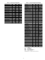
1
PREMIERLINK™ Retrofit Rooftop Controller Version 3.x Application Data Part Number 33CSPREMLK CONTENTS Page SAFETY CONSIDERATIONS . . . . . . . . . . . . . . . . . . . . . . 1 GENERAL . . . . . . . . . . . . . . . . . . . . . . . . . . . . . . . . . . . . . . 1-8 Physical Characteristics . . . . . . . . . . . . . . . . . . . . . . . . . 2 PremierLink Controller Hardware. . . . . . . . . . . . . . . . . 2 Field-Supplied Hardware . . . . . . . . . . . . . . . . . . . . . . . . . 2 Location of PremierLink Controller. . . . . . . . . . . . . . . 7 Inputs and Outputs. . . . . . . . . . . . . . . . . . . . . . . . . . . . . . . 7 Control Wiring . . . . . . . . . . . . . . . . . . . . . . . . . . . . . . . . . . . 8 APPLICATION DATA . . . . . . . . . . . . . . . . . . . . . . . . . . . .8-11 Rooftop Applications. . . . . . . . . . . . . . . . . . . . . . . . . . . . . 8 Heat Pump Applications . . . . . . . . . . . . . . . . . . . . . . . . . 9 Thermostat Applications . . . . . . . . . . . . . . . . . . . . . . . . . 9 Demand Controlled Ventilation . . . . . . . . . . . . . . . . . . . 9 Dehumidification of Fresh Air with Demand Controlled Ventilation . . . . . . . . . . . . . . . . . . . . . . . . . 11 Humidi-MiZer® Applications . . . . . . . . . . . . . . . . . . . . . 11 USER INFORMATION SCREENS. . . . . . . . . . . . . . 11-15 SEQUENCE OF OPERATION . . . . . . . . . . . . . . . . . 16-19 Indoor Fan Control . . . . . . . . . . . . . . . . . . . . . . . . . . . . . . 16 Economizer Control Sensor Cooling . . . . . . . . . . . . 16 DX Cooling . . . . . . . . . . . . . . . . . . . . . . . . . . . . . . . . . . . . . . 16 Cooling Control Submaster Loop (CCSR) . . . . . . . 16 Heating. . . . . . . . . . . . . . . . . . . . . . . . . . . . . . . . . . . . . . . . . . 17 Dehumidification . . . . . . . . . . . . . . . . . . . . . . . . . . . . . . . . 17 Indoor Air Quality (IAQ) Monitoring . . . . . . . . . . . . . 17 Remote Timeclock/Door Switch . . . . . . . . . . . . . . . . . 17 Linkage Operation . . . . . . . . . . . . . . . . . . . . . . . . . . . . . . 17 Uncooling Free Cooling . . . . . . . . . . . . . . . . . . . . . . . . . 17 Demand Limit . . . . . . . . . . . . . . . . . . . . . . . . . . . . . . . . . . . 18 Diagnostic Test . . . . . . . . . . . . . . . . . . . . . . . . . . . . . . . . . 18 Space Sensor Set Point Adjust . . . . . . . . . . . . . . . . . . 18 Timed Override. . . . . . . . . . . . . . . . . . . . . . . . . . . . . . . . . . 18 Temperature Compensated Start . . . . . . . . . . . . . . . . 18 Power Exhaust . . . . . . . . . . . . . . . . . . . . . . . . . . . . . . . . . . 18 Network Modules. . . . . . . . . . . . . . . . . . . . . . . . . . . . . . . . 18 Alarms . . . . . . . . . . . . . . . . . . . . . . . . . . . . . . . . . . . . . . . . . . 18 GUIDE SPECIFICATIONS . . . . . . . . . . . . . . . . . . . . . 19-23 SAFETY CONSIDERATIONS SAFETY NOTE This equipment will provide safe and reliable service when operated within design specifications. The equipment should be operated and serviced only by authorized personnel who have a thorough knowledge of system operation, safety devices and emergency procedures. Good judgement should be used in applying any manufacturer’s instructions to avoid injury to personnel or damage to equipment and property. WARNING Disconnect all power to the unit before performing maintenance or service. Unit may automatically start if power is not disconnected. Electrical shock and personal injury could result. CAUTION Damage to equipment may result. An individual fieldsupplied 24-vac power transformer is strongly recommended for each PremierLink controller. The transformer must be less than 100 va to meet UL (Underwriters Laboratories) Class 2. GENERAL The PremierLink retrofit rooftop controller is an intelligent control that continuously monitors and regulates rooftop operation. The PremierLink controller is compatible with the Carrier Comfort Network® (CCN) system. The controller is designed to allow users the access and ability to change factory-defined settings, thus expanding the function of the standard unit control board. IMPORTANT: PremierLink part number 33CSPREMLK should only be used in applications where the integrity of the Underwriters Laboratories rating will be maintained. Carrier’s diagnostic standard tier display tools such as System Pilot™ or Touch Pilot™ devices can be used with the PremierLink controller. Access is available via an RJ-11 connection or a 3-wire connection to the communication bus. User interfaces available for use with the CCN system are PC’s equipped with Carrier user interface software such as Service Tool, ComfortVIEW™, or ComfortWORKS® software. When used as part of the CCN system, other devices such as the CCN data transfer or Comfort Controller can read data from or write data to the PremierLink retrofit controller. The PremierLink controller offers ventilation monitoring with an optional CO2 ventilation sensor. The CO2 ventilation sensor measures the amount of ventilation needed by the space and a PID (Proportional Integral Derivative) calculation makes adjustments to the economizer minimum position during occupied operation. The indoor CO2 level will be compared to an outdoor CO2 reference level before making adjustments to the economizer minimum position. The PremierLink controller will provide intelligent compressor staging and economizer operation when connected to a space sensor with set point adjustment, timed override and a service port jack. The intelligent compressor staging and the economizer control use error reduction logic as designated in Manufacturer reserves the right to discontinue, or change at any time, specifications or designs without notice and without incurring obligations. Section 10 Catalog No. 04-51330005-01 Printed in U.S.A. Form 33CS-4XA Pg 1 10-10 Replaces: 33CS-3XA Tab 10d • • • • ASHRAE 90.1 (American Society of Heating, Refrigeration, and Air Conditioning Engineers). The error reduction logic provides better temperature control and reduced energy usage. The PremierLink™ controller provides communication to the System Pilot™ interface. The sensor allows for set point adjustment, timed override, force fan and will read equipment mode. The sensor will also measure and maintain room temperature. wire harness 10 spade connectors wire nuts 4 no. 6 x 1-in. self-drilling Phillips pan head mounting screws Field-Supplied Hardware — Each PremierLink controller requires the following field-supplied components to complete its installation: • space temperature sensor (33ZCT55SPT, 33ZCT56SPT, or 33ZCT59SPT) in sensor mode or in thermostat mode for economizer control • supply air temperature sensor (33ZCSENSAT) required for all applications • indoor air quality sensor (33ZCSENCO2, 33ZCT55CO2, 33ZCT56CO2) required for demand control ventilation • outdoor air quality sensor (33ZCSENCO2) required for demand control ventilation • indoor relative humidity sensor (33ZCSENSRH-01) required for dehumidification • outdoor air temperature sensor (33ZCSENOAT) • enthalpy and differential enthalpy sensors (33CSENTHSW and 33CSENTSEN). SPACE TEMPERATURE (SPT) SENSOR — The PremierLink controller can be used with any combination of CO2 and space temperature sensors. Refer to the instructions supplied with each sensor for electrical requirements. See Fig. 3 and Table 1. There are three types of SPT sensors available from Carrier: • 33ZCT55SPT space temperature sensor with timed override button • 33ZCT56SPT space temperature sensor with timed override button and set point adjustment • 33ZCT59SPT, space temperature sensor with LCD (liquid crystal display) screen, override button, and set point adjustment. The sensor should be mounted approximately 5 ft from the floor, in an area representing the average temperature in the space. Allow at least 4 ft between the sensor and any corner and mount the sensor at least 2 ft from an open doorway. The SPT sensor wires are to be connected to terminals in the unit’s main control board. SUPPLY AIR TEMPERATURE (SAT) SENSOR — The 33ZCSENSAT supply air temperature sensor is required for controller operation. The sensor consists of a thermistor encased within a stainless steel probe. See Fig. 4. The SAT sensor probe is 6-in. nominal length with 114 in. of unshielded, 2-conductor 18 AWG twisted-pair cables. The sensor temperature range is –40 to 245 F with a nominal resistance of 10,000 ohms at 77 F. The sensor measures accuracy of ±0.36 F. See Table 1. NOTE: The sensor must be mounted in the discharge of the unit, downstream of the cooling coil and heat exchanger. Be sure the probe tip does not come in contact with any of the unit surfaces. Ideally, the SAT sensor should be located inside the unit under the heat exchanger. The SAT sensor can also be installed in the supply air duct downstream from unit heat source to control. Physical Characteristics — The PremierLink controller is microprocessor based and includes an electronic board assembly, terminal blocks, and internal relays. Field wiring is 18 and 22 AWG (American Wire Gage). The PremierLink controller is a NEC (National Electrical Code) Class 2 rated device. The power supply is 2-wire, 24 vac (±15% at 40 va) 60 Hz. Power consumption during normal operation is between 18 and 32 vac. The controller also has internal flash memory of 128K. The PremierLink controller space temperature range is –40 to 245 F (–40 to 118 C). The controller has an allowable control set point range from 40 to 90 F (4 to 32 C) for heating and 45 to 99 F (7 to 37 C) for cooling. The PremierLink controller is designed to be used with the Carrier Comfort Network® (CCN) system. As part of this design the controller is equipped with a 365-day software clock. A software clock differs from a hardware clock as there is no battery or capacitor that backs up the clock during a power failure. After a power failure the PremierLink controller will send out a message requesting the time from a CCN time broadcast device. Once the time broadcast is received, the PremierLink clock will be set and normal time functions will resume. If stand alone operation is desired, it is recommended that a System Pilot thermostat be used. A room sensor may be used in conjunction with a switch or dry contacts to switch the PremierLink controller from unoccupied to occupied operation as needed. The PremierLink controller may also be reconfigured to use a standard thermostat if desired. The number of PremierLink controllers is limited only by the maximum number of PremierLink controllers allowed on a CCN system. Bus length may not exceed 4000 ft (1219 m), with no more than 60 devices on any 1000 ft (305 m) section. Optically isolated RS-485 repeaters are required every 1000 ft (305 m). Status and control data is transmitted at a baud rate of between 9600 and 38.4K. See Fig. 1 for typical PremierLink wiring. The default address is 0,31. The default baud rate is 9600. The Network Service Tool can be used to change the address and baud rate. Two activity indicators present on the PremierLink controller indicate activity. A green LED (light-emitting diode) will indicate activity on the communication port and a red LED will indicate status of processor operation. The controller environmental ratings are as follows: • Operating Temperature: –40 to 158 F (–40 to 70 C) at 10 to 95% RH (non-condensing) • Storage Temperature: –40 to 185 F (–40 to 85 C) at 10 to 95% RH (non-condensing) PremierLink Controller Hardware (See Fig. 2) — The PremierLink controller hardware package consists of the following hardware: • control module 2 3 Fig. 1 — Typical PremierLink™ System Wiring NOTES: 1. Ground the communication bus shield at only one end of the bus. 2. PremierLink controllers (33CSPREMLK) are normally mounted inside the HVAC unit. PremierLink controllers that are mounted outside the HVAC unit require a water proof enclosure. T56 33CSPREMLK Fig. 2 — PremierLink™ Controller 3.90 3.00 .175 DIA x .600 .08 .39 FOAM GASKET .40'' O.D. .250 ±.01 Dia 5.5 ±.5 Cool Warm PLENUM RATED CABLE 114'' ±6 Fig. 3 — Space Temperature/Room Humidity Sensor (P/N 33ZCT56SPT Shown) NOTE: Dimensions are in inches. Fig. 4 — Supply Air Temperature Sensor (P/N 33ZCSENSAT) 4 Table 1 — Thermistor Resistance vs Temperature Values for Space Temperature Sensor and Supply-Air Temperature Sensor TEMP (C) –40 –35 –30 –25 –20 –15 –10 –5 0 5 10 15 20 25 30 35 40 45 50 55 60 65 70 TEMP (F) –40 –31 –22 –13 –4 5 14 23 32 41 50 59 68 77 86 95 104 113 122 131 140 149 158 INDOOR AIR QUALITY CO2 SENSOR — The indoor air quality (IAQ) sensor monitors carbon dioxide (CO2) levels in conditioned air space. This is achieved by using infrared technology to measure the levels of CO2 present in the air. The wall sensor is available with or without an LCD (liquid crystal display) readout to display the CO2 level in ppm. See Fig. 5 and 6. The CO2 sensors are all factory set for a range of 0 to 2000 ppm and a linear mA output of 4 to 20. Refer to the instructions supplied with the CO2 sensor for electrical requirements and terminal locations. To accurately monitor the quality of the air in the conditioned air space, locate the sensor near a return air grille (if present) so it senses the concentration of CO2 leaving the space. The sensor should be mounted in a location to avoid direct breath contact. Three different CO2 sensors are available for this application: • 33ZCSENCO2 sensor is an indoor, wall-mounted sensor with an LCD display. • 33ZCT55CO2 sensor is an indoor, wall-mounted sensor without display. The CO2 sensor also includes a space temperature sensor with override button. See Fig. 6. • 33ZCT56CO2 sensor is an indoor, wall-mounted sensor without display. The CO2 sensor also includes a space temperature sensor with override button and temperature offset. OUTDOOR AIR QUALITY (OAQ) CO2 SENSOR — The outdoor air CO2 sensor is designed to monitor carbon dioxide (CO2) levels in the air and interface with the ventilation damper in an HVAC (heating, ventilation, and air conditioning) system. The OAQ sensor requires an outdoor cover. An accessory outdoor enclosure (33ZCOA-CO2) can be used. The OAQ sensor is used as an outdoor CO2 reference to maintain a differential CO2 level in the space per ASHRAE 62.99. The outdoor CO2 level may also be forced to a fixed outdoor ambient CO2 level. When no CO2 sensor is detected, the controller will use 400 ppm as the default outdoor CO2 level. RESISTANCE (Ohms) 335,651 242,195 176,683 130,243 96,974 72,895 55,298 42,315 32,651 25,395 19,903 15,714 12,494 10,000 8,056 6,530 5,325 4,367 3,601 2,985 2,487 2,082 1,752 OUTDOOR AIR TEMPERATURE SENSOR — The outdoor air temperature (OAT) sensor (33ZCSENOAT) monitors the temperature outside of the outside air entering the equipment. The OAT sensor must be located properly. The sensor must be installed immediately upstream from outdoor air damper where it will accurately sense the temperature of the outdoor air entering the mixing box. For applications without economizer, the sensor may be located in the outdoor air duct near the outdoor air intake or on the exterior of the building. The thermistor has a range of –40 to 245 F and a resistance of 10,000 ohms at 77 F. Do not mount the sensor in direct sunlight. Inaccurate readings may result. Do not mount the sensor near the exhaust from air-handling units or compressors, near leakage drafts of indoor air, or near shrubbery or trees, or under direct water runoff. ENTHALPY AND DIFFERENTIAL ENTHALPY SENSORS — The accessory enthalpy switch/receiver (33CSENTHSW) senses temperature and humidity of the air surrounding the device and calculates the enthalpy when used without an enthalpy sensor. The relay is energized when enthalpy is high and deenergized when enthalpy is low (based on ASHRAE 90.1 criteria). If an accessory enthalpy sensor (33CSENTSEN) is attached to the return air sensor input, then differential enthalpy is calculated. The relay is energized when the enthalpy detected by the return air enthalpy sensor is less than the enthalpy at the enthalpy switch/receiver. The relay is deenergized when the enthalpy detected by the return air enthalpy sensor is greater than the enthalpy at the enthalpy switch/receiver (differential enthalpy control). See Fig. 7 and 8. NOTE: The outdoor air quality level, outdoor air temperature, and outdoor air enthalpy may be broadcast and shared with any rooftop units on the CCN bus. RELATIVE HUMIDITY SENSOR — The 33ZCSENSRH01 relative space humidity sensor is required for dehumidification control on a rooftop unit equipped with a dehumidification device. Otherwise, the relative humidity sensor is used for monitoring only. NOTE: The relative humidity sensor and the outdoor air CO2 sensor cannot both be used on the controller at the same time. 5 5.625 (14.3) 5 (12.7) 3.25 (8.3) 1.125 (2.9) 0.25 (0.8) NOTE: Dimensions are in inches. Dimensions in ( ) are in centimeters. Fig. 5 — Indoor Air Quality (CO2) Sensor (33ZCSENCO2) with Display Fig. 7 — Enthalpy Switch/Receiver Dimensions (33CSENTHSW) Fig. 6 — Indoor Air Quality (CO2) Sensor (33ZCT55CO2) Without Display Fig. 8 — Enthalpy Sensor Dimensions (33CSENTSEN) 6 In some equipment, the integrated gas control (IGC) board may run the fan for 90 to 120 seconds depending on the mode, if heat was on during the fire shutdown command. Operation of the fan after the command to shut down may not be acceptable to the local inspector. If that is the case, another relay must be added to drop power to the IGC for a fire shutdown. When the fan output goes off, the compressors can be programmed to turn off after their minimum runtime delay has elapsed. This is to protect the compressors in case the shutdown command would cause compressor short cycling. This systematic shutdown is acceptable with nationally adopted fire codes. The compressors can also be programmed to go off immediately if it is required by the local inspectors. SUPPLY FAN STATUS — The Supply Fan Status input is a 24-vac input used by the PremierLink control to determine if the fan is actually operational after it has been commanded on. If the supply fan status disagrees with the Supply Fan output, then an alarm will be generated and heating and cooling will be terminated. Compressors may run for a short time to satisfy the minimum compressor runtime. ENTHALPY STATUS — The Enthalpy Status input is a 24-vac input that is used by the PremierLink controller to determine if the outdoor enthalpy is high or low. HEAT 3/EXHAUST FAN/REVERSING VALVE/DEHUMDIFY/OCCUPIED — This output is a 24-vac output that can be used to control a third stage of heat, an exhaust fan, or a reversing valve for a heat pump unit. To use the output as a third stage of heat, two configuration settings must be changed. The AUXOUT configuration (see User Information Screens section on page 11) must be set to 2 and Heat Stages number of stages in service configuration must be set to 3 (see User Information Screens section on page 11). To use this output to turn an exhaust fan on and off based on damper position, set the AUXOUT configuration (see User Information Screens section on page 11) to 1 and set the desired damper position in the set point schedule PES (see User Information on Screens section on page 11). To use this output to run the exhaust fan, lights, or other applications when occupied, set the AUXOUT configuration to 1 (see User Information Screens section on page 11) and set MODPE in the service configuration to Enable (see User Information Screens section on page 11). This output will turn on any time the mode is occupied. The temperature compensated start mode is considered occupied mode. If temperature compensated start is being allowed to function, the PremierLink controller enters Occupied mode Location of PremierLink™ Controller — The PremierLink controller should be located inside one of the available service access panels of the unit. Be sure the location selected prevents moisture and rain from coming into contact with the circuit board. Select a location which will be safe from water damage and allow sufficient access for service and wiring. For service access, there should be at least 6 in. of clearance between the front of the PremierLink controller and adjacent surfaces. Be sure to leave 1/2-in. clearance in front of RJ-14 connector for attaching RJ-14 cable from the CCN system. A field-supplied right angle 6-pin RJ-14 connector can be attached if necessary. An accessory mounting bracket may be used to mount the PremierLink control under the rooftop unit control box. See Fig. 9. Inputs and Outputs — The PremierLink™ controller in- puts and outputs are shown in Table 2. Most of the inputs are discussed in the Field-Supplied Hardware section. The following information is provided to assist in applying other inputs and outputs. The PremierLink controller has two modes: Sensor mode and Thermostat mode. The digital inputs on connector J4 are designed to receive 24 vac and are used to receive thermostat commands in the thermostat mode. In the Sensor mode, they may be used for the features listed in Table 2. REMOTE TIMECLOCK/DOOR SWITCH — This input can be programmed to operate as a Remote Time Clock or as a Door Switch. When programmed as a Remote Time Clock and 24 vac is sensed at the remote timeclock input, the PremierLink controller will operate in the Occupied mode. When 24 vac is not present, the control will revert back to Unoccupied mode or to the local occupancy control logic. For basic operation of a newly installed PremierLink control, the unoccupied set points are 75 F and 69 F. In the Sensor mode, the PremierLink control will provide control of the equipment to maintain the space temperature between 69 and 75 F with intermittent fan. If the RMTOCC input is provided 24 vac, the PremierLink control will control to the Occupied set points (default 70 F and 74 F) as biased by the STO or T56 slider input. The fan will run continuously or intermittently with the cool or heat demand only depending on configured compliance with ASHRAE 90.1 standard. When programmed for Door Switch and 24 vac is present for a user configurable time delay of 2 to 20 minutes, the heating and cooling outputs will be deenergized. The fan will continue to operate depending on the ASHRAE 90.1 configuration decision. When 24 vac is not present, the PremierLink controller will control to normal temperature control set points. The Door Switch function can also be applied to water source heat pumps as a condensate overflow safety contact. When the condensate level rises to close a contact providing 24vac to the RMTOCC input, it will disable the mechanical cooling until the condensate level as dropped and the contact is opened. COMPRESSOR LOCKOUT — The Compressor Lockout input is a 24-vac input used by the PremierLink controller to send out an alert if either of the compressors is locked out. This was designed to be a location for feedback from the compressor lockout boards to indicate if there is trouble turning on the compressors in the rooftop unit. This input has no effect on normal compressor staging. FIRE SHUTDOWN — The Fire Shutdown input is a 24-vac input that will cause the PremierLink controller to halt fan operation and close the damper immediately in case of a fire. This input can be programmed for normally open or closed contact. All heat operation will turn off immediately after the fan shuts off. MOUNTING SCREWS UNIT CONTROL BOX MOUNTING BRACKET PREMIERLINK CONTROLLER (WITH COVER) Fig. 9 — Accessory Mounting Bracket 7 each day a few minutes before the actual configured occupancy time. To use this output to control a reversing valve, set the AUXOUT configuration to 3 to energize for heating or 4 to energize for cooling (see User Information Screens section on page 11). To use this output for Dehumidification, set the AUXOUT configuration to 5 (see User Information Screens section on page 11) and set the desired occupied and unoccupied high humidity setpoints in the SETPOINT table (see User Information Screens section on page 11). To use the output for a separate occupied schedule, set the AUXOUT configuration to 6 (see User Information Screens section on page 11) and set OCCPC63 schedule to the desired occupied time. When configured for this function, the output can be written to by data transfer, Comfort Controller, etc., over the CCN communication bus. APPLICATION DATA Rooftop Applications — The PremierLink™ controller is designed to comply with ASHRAE 90.1 and ASHRAE 62, therefore the supply fan output will remain energized when the schedule is in Occupied mode. The equipment will provide required ventilation air from the fresh air intake during occupancy and enhance economizer performance. The PremierLink controller provides intermittent fan control during Unoccupied periods. If the application is an exception to current ventilation requirements and the user would like the fan to cycle with the space demand during occupied periods, then the user can configure the ASHRAE 90.1 Supply Fan decision to No. The supply fan will only turn on when there is a demand for heating or cooling. The economizer will not operate when the space temperature requirements are satisfied. The PremierLink controller requires the use of a supply air temperature (SAT) sensor (33ZCSENSAT) for heat and cool staging in both thermostat and sensor modes. The SAT also controls leaving-air temperature to prevent the equipment supply air from becoming too cold or too hot. When in cooling mode, stages 1 and 2 utilize a low set point for supply air to prevent the refrigeration coil from icing up under diminished flow conditions and also to prevent duct condensation that could be created if low supply-air temperatures were introduced into the ductwork or diffusers. When in heating mode, the SAT high limit set point provides a maximum duct temper control point to protect heat exchangers from tripping on internal high limit safeties. The default configuration for PremierLink controller is 2-stage cooling and 2-stage heating. The controller can be configured for applications requiring different stages such as single-stage equipment, heat pump or other heating applications using the auxiliary output for the third stage of heat. The PremierLink controller is equipped with a 0 to 20 mA output that may be used to control a fresh air economizer. The PremierLink controller may also be used to stage heating and cooling in applications where no economizer is available. If no economizer is used, make sure to leave the enthalpy switch input open so that the enthalpy reads HIGH at all times and the PremierLink controller will operate the stages independent of the economizer output. Control Wiring — The PremierLink™ controller can be connected to either a Carrier-approved thermostat or CCN compatible temperature sensor. 1. Turn off power to the control box. 2. Strip the ends of the red, white, and black conductors of the communication bus cable. NOTE: When connecting the communication bus cable, a color code system for the entire network is recommended to simplify installation and checkout. 3. Use 4-connector Molex with red, white and black wires to connect the controller wires. Connect the Red (+) wire to Terminal 1. Connect the White (ground) wire to Terminal 2. Connect the Black (–) wire to Terminal 3. 4. Secure all connections in step 3 with wire nuts. 5. Insert the plug into the existing 4-pin mating connector on the base module in the main control box (Terminal J-2). 6. Restore power. Table 2 — PremierLink Controller Inputs and Outputs INPUTS POWER AI (10K Thermistor) AI (10K Thermistor) AI (10K Thermistor) AI (10K Thermistor) (4-20 mA) (0-20 mA) DI (24 VAC) DI (24 VAC) DI (24 VAC) DI (24 VAC) DI (24 VAC) DI (24 VAC) POWER 4-20 mA DO Relay (24 VAC, 1A) DO Relay (24 VAC, 1A) DO Relay (24 VAC, 1A) DO Relay (24 VAC, 1A) DO Relay (24 VAC, 1A) DO Relay (24 VAC, 1A) SPACE TEMPERATURE (SPT) SET POINT ADJUSTMENT (STO) SUPPLY AIR TEMPERATURE (SAT) OUTDOOR AIR TEMPERATURE (OAT) IAQ SENSOR (IAQ) OUTDOOR AQ SENSOR/ROOM HUMIDITY (OAQ/IRH) REMOTE TIME CLOCK (RMTOCC) COMPRESSOR LOCKOUT (CMPSAFE) FIRE SHUTDOWN (FSD) SUPPLY FAN STATUS (SFS) FILTER STATUS SWITCH (FLTS) ENTHALPY STATUS (ENTH) OUTPUTS ECONOMIZER (ECONPOS) FAN (SF) COOL STAGE 1 (CMP1) COOL STAGE 2 (CMP2) HEAT STAGE 1 (HS1) HEAT STAGE 2 (HS2) HEAT 3/EXHAUST/REVERSING VALVE (HS3/EXH/RVS) LEGEND AI — Analog Input DI — Digital Input DO — Digital Output 8 TERMINAL(S) J6-7, J6-6 J6-5, J6-6 J6-3, J6-4 J6-1, J6-2 J5-5, J5-6 J5-2, J5-3 / J5-2, J5-4 J4-11, J4-12 J4-9, J4-10 J4-7, J4-8 J4-5, J4-6 J4-3, J4-4 J4-1, J4-2 TERMINALS J9-1, J9-2 J8-18 J8-15 J8-12 J8-9 J8-6 J8-3 • • • • OAT must be less than SPT Enthalpy is LOW May be jumper if Enthalpy sensor not available Pre-cooling is done when no call from the thermostat except G. Economizer modulates to provide 70 F ECONOMIZER/DX COOLING CONTROL • Three control routines based on OAT. Improves integrated economizer and compressors usage. • Economizer modulated to maintain SAT at varying Supply Air Set Points (SASP) Routine 1 (OAT DXCTLO°F) • Y1 energized – Economizer maintains a SASP = (SATLO1 + 3) • Y2 energized – Economizer maintains a SASP = (SATLO2 + 3) Routine 2 (DXCTLO < OAT < 68 F) • Y1 energized - Economizer maintains a SASP = (SATLO1 + 3) - If SAT > SASP + 5 and economizer position 80% - Economizer will go to minimum position for 3 minutes or until SAT > 68 F - First stage of mechanical cooling will be energized. - Integrator resets - Economizer opens again and controls to SASP after stage one on for 90 seconds • Y2 energized - Economizer maintains a SASP = SATLO2 + 3 - If SAT > SASP + 5 and economizer position 80% - Economizer will go to minimum position for 3 minutes or until SAT > 68 F - First stage of mechanical cooling will be energized. - Integrator resets - Economizer opens again and controls to SASP after stage one on for 90 seconds The OAT sensor may be shorted out if not installed. The DXCTLO configuration may be turned off if an OAT sensor is installed or being broadcast and the user wants the cooling stages to operate below the Cooling Lockout set point DXLOCK. When Economizer operation is desired the PremierLink controller requires an OAT input and an SPT input as a minimum check to determine if the air is suitable for free cooling. This also applies to thermostat applications, so it is suggested that a sensor be installed in the return air and wired to the SPT input for thermostat applications. The enthalpy switch may be added as an extra check for more humid climates. If no enthalpy switch is installed, be sure to jumper the enthalpy switch input so that the enthalpy point reads LOW all of the time. Therefore the PremierLink controller will only check OAT and SPT to determine if conditions are good for free cooling. Heat Pump Applications — The PremierLink con- troller can be configured for use in applications with heat pumps that do not control the reversing valve from a defrost board. In addition, the controller can also be used in applications with heat pumps that include the defrost board. If the controller is installed on a Carrier heat pump with a defrost board the default (AC) configuration will apply. The CMP1 and CMP2 outputs will control cooling and the HS1 and HS2 outputs will control heat. If IAQ control with temperature tempering is desired (IAQ priority set to HIGH), the AC/HP configuration should be set for heat pump operation so HS2 will energize without HS1 for tempering. For equipment with a reversing valve, the AUXOUT output should be configured for reversing valve operation and AC configured for heat pump operation. When AUXOUT is set to 3, the reversing valve is energized when the compressors are turned on for heat and deenergized when the compressors are turned on for cooling. When AUXOUT is set to 4, the reversing valve is energized when the compressors are turned on for cooling and turned off when compressors are turned on for heating. Refer to Split System or Water Source Heat Pump manuals for more information. Thermostat Applications — The PremierLink con- troller may be used with a typical thermostat instead of a room sensor. The PremierLink controller must be reconfigured for usage with a thermostat. Economizer and DCV (demand controlled ventilation) are supported in Thermostat mode. See Fig. 10. FAN AND MINIMUM DAMPER CONTROL • Fan (G or W1 input from thermostat) must be present before cooling can operate. • With G Economizer will go to minimum position if not active. • With W1 only Economizer will stay at 0%. DX (Direct Expansion) COOLING CONTROL • Controls 2 stages of DX to satisfy Y1 and Y2 inputs from thermostat. If economizer not active. • RV energized if configured for heat pump and AUXOUT configured for reversing valve for cooling. • Compressors Cycled off at configurable SAT values for SAT control. • SATLO1 (default 55 F) • SATLO2 (default 50 F) ECONOMIZER COOLING CONTROL • Economizer active requires SPT, SAT, and OAT • SPT device may be mounted in return air • OAT must be less than 75 F Routine 3 (OAT > 68) • Economizer is opened 100% • Compressors 1 and 2 are cycled based on Y1 and Y2 HEATING CONTROL Gas Heat, Electric Heat, and Heat Pump with Internal Reversing Valve • Indoor Fan will be on for electric heat. • Heat 1 follows W1 input. • Heat 2 follows W2 input. Heat Pump without Internal Reversing Valve and AUXOUT = Reversing Valve for Heat • Indoor fan will be on. • Compressors 1,2 and RV will follow W1 input. • Heat Stages 1,2 will follow W2 input. Demand Controlled Ventilation — Certain criteria must be considered when using the PremierLink™ controller for demand control ventilation. When selecting the heating and cooling capacity of the equipment, the maximum ventilation rate must be evaluated for design conditions along with the maximum damper position to achieve desired conditioning of the space. Typical maximum ventilation rate should be ASHRAE occupied design cfm +5 to 10%. 9 a33-9148 10 Fig. 10 — Typical Thermostat Wiring NOTE: Remove all unused red wires from J4 connector to prevent 24 vac shorting other components or ground. Inputs on J4 are 24 vac; red leads are voltage source. the proper IAQ damper position to hold the CO2 level at the configured differential set point. The PremierLink controller can also provide tempering of supply air when the space or return air temperature falls between the occupied heat and cool set points or there is not a call for heating or cooling in the Thermostat mode. The maximum ventilation airflow rate should be checked by evaluating the unit's heating capability to raise the supply air to an acceptable level during tempering of supply air. After determining the maximum ventilation airflow rate the indoor air quality (IAQ) maximum damper configuration needs to be configured. Demand control ventilation software may be used to assist in determining the CO2 maximum ventilation recovery rate. The recovery rate can be accomplished by using either proportional-anticipatory strategy or proportional integral (PI) control. Proportional-anticipatory strategy should be used in applications where installed equipment cannot exceed the required ventilation rate. In a large zone having varied occupancy, implementing proportional-anticipatory strategy will cause the fresh air supply to increase as the room CO2 level increases even though the CO2 set point has not been reached. By the time the CO2 level reaches the set point the damper will be at maximum ventilation and will maintain the set point. Equipment installed in a small zone that has capacity to occasionally exceed the required ventilation rate and still has enough capacity to maintain comfort will not energize until the CO2 set point is reached. Once this occurs, the unit will then regulate the fresh air using proportional integral derivative (PID) loop to maintain the required ventilation. For the IAQ control to be effective, the maximum damper position needs to allow enough ventilation air in to decrease the CO2 level at maximum occupancy or supply enough ventilation air to hold the CO2 level at its current position. If the maximum fresh air can reduce the space CO2 level, the differential set point should be set to the desired level. If the maximum ventilation air can only maintain the set point, then the differential set point should be set far enough below the required level so the damper will be at IAQ maximum position when the required differential is reached. PROPORTIONAL INTEGRAL DERIVATIVE (PID) CONTROL — The PremierLink controller is configured for PID control for CO2 level with a starting value of zero. As the CO2 differential set point is exceeded the controller will start calculating an IAQ damper position based in the PI calculations. As the IAQ damper position exceeds either the current minimum position or economizer damper position, the IAQ damper position will become the economizer position. As long as the CO2 level is high due to zone occupancy, the PID loop will maintain Dehumidification of Fresh Air with Demand Controlled Ventilation — The PremierLink controller can be used with a heat recovery unit to reduce the moisture content of the fresh air being brought in when the enthalpy is high. To assist in the control of dehumidification, either an enthalpy or differential enthalpy switch should be installed on the equipment to enable dehumidification when economizer operation is not possible. Humidi-MiZer® Applications — The PremierLink controller can be used in applications with the Humidi-MiZer Adaptive Dehumidification system. For PremierLink versions 2.0 and later, the humidity sensor input can be wired directly into the PremierLink controller. The output will be energized whenever the attached Indoor Relative Humidity (RH) sensor exceeds the unoccupied or occupied high RH set point. This function will not bring on the compressors but is designed to work with MoistureMi$er or Humidi-MiZer option on Carrier rooftop units. If the unoccupied set point is exceeded, the control will also turn on the fan. Refer to the Humidi-MiZer application data for further details. USER INFORMATION SCREENS The following section describes the computer user information screens, which are used to monitor and configure the PremierLink™ controller. The screens shown may be displayed differently when using different Carrier software. The following configuration screens are provided: • Points Display (Table 3) • Thermostat Control Input Display (Table 4) • Alarm Service Configuration (Table 5) • Controller Identification (Table 6) • Holiday Configuration (Table 7) • Occupancy Configuration (Table 8) • Service Configuration Selection (Table 9) • PremierLink Control Configuration (Table 10) • Set Point Configuration (Table 11) • Occupancy Maintenance (OCCPC63S-64S) (Table 12) • Primary Maintenance (MAINT) (Table 13) • System Pilot Maintenance (SP_MAINT) (Table 14) • System Pilot Alternate Maintenance Display (ALT_DISP) (Table 15) Refer to the PremierLink Controller Installation Instructions for more information on configuring the controller. 11 Table 3 — Points Display DESCRIPTION Space Temperature Supply Air Temperature Outdoor Air Temperature Control Setpoint Rooftop Mode Cooling % Total Capacity Heating % Total Capacity Economizer Active Supply Fan Relay Supply Fan Status Economizer Position Current Min Damper Pos Filter Status Remote Occupied Mode Heat Stage 1 Heat Stage 2 Ht 3/Exhaust/Rev Valv/DH Enthalpy Indoor Air Quality Indoor Air Quality Setpt Outdoor Air Quality Indoor RH Fire Shutdown SPT Offset Compressor 1 Compressor 2 Compressor Safety Rooftop Mode LON Setpoint Alarm Status VALUE 72.2 67.1 48.8 70.0 COOL 0 0 Yes On On 26.2 20 Clean Off Off Off Off Low 367.9 1050.0 0.0 0 Normal 0.0 Off Off Off 2 72 Normal UNITS dF dF dF dF STATUS FORCE NAME SPT SAT OAT CLSP MODE CCAP HCAP ECOS SF SFS ECONPOS IQMP FLTS RMTOCC HS1 HS2 H3_EX_RV ENTH IAQI IAQS OAQ IRH FSD STO CMP1 CMP2 CMPSAFE RTU_MODE LON_SP ALARM FORCE NAME Y1 Y2 W1 W2 G % % % % % ^F dF LEGEND SPT — Space Temperature Sensor NOTE: Bold values indicate points that can be forced through communications. Table 4 — Thermostat Control Input Display DESCRIPTION Y1 - Call for Cool 1 Y2 - Call for Cool 2 W1 - Call for Heat 1 W2 - Call for Heat 2 G - Call for Fan VALUE On On Off Off On UNITS STATUS NOTE: Bold values indicate points that can be forced through communications. Table 5 — Alarm Service Configuration DESCRIPTION Alarm Control Alarm Routing Control Realarm Time Control Temp Hysteresis Control Humid Hysteresis Supply Air Temperature Low Limit High Limit IAQ High Alert Limit Low Limit High Limit Fire Inp Alm Conditn VALUE UNITS 00000000 0 5.0 5 min ^F % ALRMCNT REALARM SPTHYS RHHYS dF dF LOWLIM HIGHLIM 45.0 150.0 0.0 1200.0 Normal Table 6 — Controller Identification NAME DESCRIPTION Description: Location: Software Part Number: Model Number: Serial Number: Reference Number: VALUE Rooftop Control UNITS CESR131269-08 Version 2.000 NAME DevDesc Location PartNum ModelNum SerialNo RefNum NOTE: Bold values are configurable through communications. Table 7 — Holiday Configuration LOWLIM HIGHLIM FIAC DESCRIPTION Start Month Start Day Duration LEGEND IAQ — Indoor Air Quality NOTE: Bold values are configurable through communications. VALUE 1 1 0 UNITS NAME MONTH DAY DURATION NOTE: Bold values are configurable through communications. 12 Table 8 — Occupancy Configuration DESCRIPTION Manual Override Hours Period 1: Day of Week Period 1: Occupied from Period 1: Occupied to Period 2: Day of Week Period 2: Occupied from Period 2: Occupied to Period 3: Day of Week Period 3: Occupied from Period 3: Occupied to Period 4: Day of Week Period 4: Occupied from Period 4: Occupied to Period 5: Day of Week Period 5: Occupied from Period 5: Occupied to Period 6: Day of Week Period 6: Occupied from Period 6: Occupied to Period 7: Day of Week Period 7: Occupied from Period 7: Occupied to Period 8: Day of Week Period 8: Occupied from Period 8: Occupied to VALUE UNITS 0 hours 11111111 00:00 24:00 00000000 00:00 24:00 00000000 00:00 24:00 00000000 00:00 24:00 00000000 00:00 24:00 00000000 00:00 24:00 00000000 00:00 24:00 00000000 00:00 24:00 Table 9 — Service Configuration Selection NAME OVRD DOW1 OCC1 UNOCC1 DOW2 OCC2 UNOCC2 DOW3 OCC3 UNOCC3 DOW4 OCC4 UNOCC4 DOW5 OCC5 UNOCC5 DOW6 OCC6 UNOCC6 DOW7 OCC7 UNOCC7 DOW8 OCC8 UNOCC8 DESCRIPTION Cooling PID Proportional Gain Integral Gain Derivative Gain Starting Value SAT CMP1 Low Setpoint SAT CMP2 Low Setpoint Staged Cooling Total Number of Stages Stage 1 Time Guard Stage 2 Time Guard Stage 3 Time Guard Heating PID Proportional Gain Integral Gain Derivative Gain Starting Value SAT High Setpoint Staged Heating Total Number of Stages Stage 1 Time Guard Stage 2 Time Guard Stage 3 Time Guard IAQ PID Proportional Gain Integral Gain Derivative Gain Starting Value Economizer PID Proportional Gain Integral Gain Derivative Gain Starting Value Submaster Gain Limit Submaster Center Value Damper Movement Band OAT Temp Band Minimum Damper Position Low Temp MDP Override DX Cooling Lockout DX Cooling Lockout Temp Time Guard Override Continuous Power Exhaust Supply Fan Status Enable Remote Cont/Door Switch ASHRAE 90.1 Supply Fan Min Setpoint Deadband Max OAT for Free Cool Max Offset Adjustment Comp Time Gard for Fire Comp Min Off Time Comp Min On Time Mode Change Time Space Temp Trim Supply Air Temp Trim NOTE: Bold values are configurable through communications. DX IAQ OAT PID SAT — — — — — VALUE 6.0 3.0 5.0 70.0 55 50 UNITS dF dF dF 2 Enable Enable Disable 6.0 3.0 5.0 75.0 140 -4.0 -2.0 -3.0 70.0 -5.5 60 0 25 20 100 On 45.0 Off Disable Disable 0 Yes 1.5 75 2.0 Yes 5 3 10 0.0 0.0 KP KI KD STARTVAL SATLO1 SATLO2 STAGES TG1 TG2 TG3 dF dF 2 Enable Enable Enable 0.1 0.5 0.0 0.0 NAME KP KI KD STARTVAL SATHI STAGES TG1 TG2 TG3 % dF % % dF % % dF ^F dF ^F min min min ^F ^F KP KI KD STARTVAL KP KI KD STARTVAL ESG CTRVAL ECONBAND TEMPBAND MDP LOWMDP DXCTLO DXLOCK TGO MODPE SFSENABL RC_DS CONTFAN MIN_DBND OATMAX LIMT COMP_TG C_MIN_OF C_MIN_ON M_SELECT RATTRIM SATTRIM LEGEND Direct Expansion Indoor Air Quality Outdoor-Air Temperature Proportional Integral Derivative Supply Air Temperature NOTE: Bold values are configurable through communications. 13 Table 10 — PremierLink™ Control Configuration DESCRIPTION VALUE UNITS 0=TSTAT, 1=CCN Sensor 0 0=Gas, 1=Electric Heat 0 0=AC Unit, 1=Heat Pump 0 Auxiliary Output 0 0=None 1=Exhaust Fan 2=Heat Stage 3=Reversing Valve Heat 4=Reversing Valve Cool 5=Dehumidification 6=Separate Schedule Unnoc Free Cool 0 0=Disable 1=Always enabled 2-6 Hours prior to OCC Demand Limiting Disable Loadshed Group Number 1 CCN Broadcast OAT, ENTH,OAQ 0 Global Schedule Broadcast No Broadcast Acknowledge No Schedule Number 64 Timed Override Hours 0 hours Global Override Enable Yes Linkage Thermostat Cool Strt Bias(min/deg) 10 min Heat Strt Bias(min/deg) 10 min Filter Timer hrs* 100 15 IAQ Priority Level Low IAQ Pre-Occupancy Purge Disable IAQ Purge Duration 5 min IAQ Delta Setpoint 650 IAQ Maximum Damper Pos. 50 % Indoor AQ Low Ref. 0.0 Indoor AQ High Ref. 2000.0 Outdoor AQ Low Ref. 0.0 Outdoor AQ High Ref. 2000.0 Outdoor AQ Lockout Point 0 CCN ENTH IAQ OAQ OAT — — — — — Table 11 — Set Point Configuration NAME TSTATCFG HEATTYPE AC AUXOUT DESCRIPTION Setpoints Occupied Low Setpoint Occupied High Setpoint Unoccupied Low Setpoint Unoccupied High Setpoint Hi OAT Lckout for TSTAT Unocc. OAT Lockout TEMP Unocc. Heating Deadband Unocc. Cooling Deadband Low Temp. Min. Position Hi Temp. Min. Position Power Exhaust Setpoint Occ Rel Hum Setpoint Unocc Rel Hum Setpoint NTEN DLEN LSGP OATBC GSBC BCACK SCHEDNUM TIMOVRID GLOB_OV VALUE 70.0 74.0 69.0 75.0 65.0 50.0 1.0 1.0 10 35 50 50 99 UNITS NAME dF dF dF dF dF dF ^F ^F % % % % % OHSP OCSP UHSP UCSP OATL NTLO UHDB UCDB LTMP HTMP PES ORHS URHS LEGEND OAT — Outdoor Air Temperature NOTE: Bold values are configurable through communications. Table 12 — Occupancy Maintenance Screen (OCCPC63S-64S) DESCRIPTION Mode Current Occupied Period Override in Progress Override Duration Occupied Start Time Unoccupied Start Time Next Occupied Day Next Occupied Time Next Unoccupied Day Next Unoccupied Time Last Unoccupied Day Last Unoccupied Time KCOOL KHEAT FIL_TIMR IAQP IAQPURGE IQPD IAQD IAQMAXP IIAQREFL IIAQREFH OIAQREFL OIAQREFH OIAQLOCK LEGEND Carrier Comfort Network® Enthalpy Indoor Air Quality Outdoor Air Quality Outdoor Air Temperature NOTE: Bold values are configurable through communications. 14 VALUE 0 0 No 0 00:00 00:00 00:00 00:00 00:00 UNITS min NAME MODE PERIOD OVERLAST OVERDURA OCCSTART UNSTART NXTOCCD NXTOCCT NXTUNOD NXTUNOT PRVUNOD PRVUNOT Table 13 — Primary Maintenance Screen (MAINT) DESCRIPTION VALUE Thermostat Control Occupied Override Time Remaining Timed Override in Effect Start Bias Time Heat Cool IAQ Control Demand Limit Temp Compensated Start IAQ Pre-Occupancy Purge Unoccupied Free Cool Fire Shutdown Linkage Control Field/Startup Test Heat Submaster Ref Cool Submaster Ref Economizer Submaster Ref Economizer Submastr Gain Compressor Starts Compressor 1 Runtime Compressor 2 Runtime Supply Fan Runtime Reset Statistics AUXOUT Schedule Linkage Thermostat Linkage Status Supervisory Element Supervisory Bus Supervisory Block Average Occ Heat Setpt Average Occ Cool Setpt Average Unoc Heat Setpt Average Unoc Cool Setpt Average Zone Temp Average Occ Zone Temp Occupancy Status(1=occ) UNITS No Yes 0 No 0 No No No No No No No No No No 40.0 150.0 120.0 0.00 0.00 0.00 0.00 17.00 No Yes 2 0 0 0 0.0 0.0 0.0 0.0 0.0 0.0 1 STATUS FORCE NAME TSTAT OCCUP OVRTIMER TIMOV STRTBIAS HEAT COOL IAQCL DEMLT TCSTR IQPRG NTFCL FIRES DAVCL FIELD SHSR CCSR ECONSR ECONGN CMPST CM1RT CM2RT FANRT STAT_RES AUXSCHED min min dF dF dF HOURS HOURS HOURS LINKSTAT SUPE-ADR SUPE-BUS BLOCKNUM OCLOSTPT OCHISTPT UNLOSTPT UNHISTPT AZT AOZT OCCSTAT dF dF dF dF dF dF LEGEND IAQ — Indoor Air Quality OCC — Occupancy UNOC — Unoccupied NOTE: Bold values indicate points that can be forced through communications. Table 15 — System Pilot Alternate Maintenance Display Table (ALT_DISP) Table 14 — System Pilot Maintenance Table (SP_MAINT) DESCRIPTION Rooftop Mode VALUE COOL Control Setpoint 70 Linkage Master No Space Temperature 73 Occupied Yes Occupied Heat Setpoint 70 Occupied Cool Setpoint Unoccupied Heat Setpoint Unoccupied Cool Setpoint UNITS 74 69 75 dF dF NAME DESCRIPTION MODE Supply Air Temperature CLSP Cooling % Total Capacity LINKMAST Heating % Total Capacity SPT Outdoor Air Temperature Enthalpy Low ZONEOCC dF dF dF dF VALUE UNITS 66.5 dF SAT 0 % CCAP 0 % HCAP 74.8 dF OHSP Economizer Position 20 OCSP Indoor Air Quality 0 UHSP Filter Status UCSP Indoor RH 15 OAT ENTH % ECONOS IAQI Clean 0 NAME FLTS % IRH • OCCUPIED, TEMP.COMPENSATED START or COOL mode is active. • SPT reading is available. • Low ambient lockout of DX cooling is not activated. If all of the above conditions are met, the cooling reference will be calculated, otherwise it is set to its maximum value. If any of the qualifying conditions above are not met, the cooling and submaster references are set to the maximum limit. The PremierLink controller controls the cooling stages to maintain set point temperature. Room temperature can go above and below the set point by the same amount for each cycle. Smart staging works to reduce the cooling time by using both stages when conditions are right. As OAT temperature comes down, the second stage will not be used to allow the first stage of cooling to cool the space with economizer. The Premierlink control uses the resources available for optimum performance. See Fig. 12. This provides better temperature control and uses less energy than control by a conventional thermostat. LOW AMBIENT LOCKOUT OF DX COOLING — Low ambient lockout of DX cooling will take place if all of the following conditions are met: • OAT reading is available • DXCTLO option is enabled • OAT DXLOCK SEQUENCE OF OPERATION NOTE: Refer to the instruction manual supplied with the unit for specific operating instructions. Indoor Fan Control — The indoor fan control will operate the unit at all times in one or more operating modes. In Occupied mode, the fan will be ON continuously if ASHRAE 90.1 Supply Fan is set to Yes (default). If ASHRAE 90.1 Supply Fan is set to No, then the fan will cycle with temperature demand. In Unoccupied mode, the fan will cycle with temperature demand. Economizer Control Sensor Cooling — The economizer dampers will provide free cooling and/or air quality control when the outside conditions are suitable. Providing free cooling is accomplished by controlling supply-air temperature (SAT) to a certain level pre-determined by the submaster reference. Air quality control is maintained as the need for fresh air becomes greater. The need for fresh air is measured by the CO2 sensor. When economizer operation is desired, the PremierLink controller requires an OAT input and an SPT input as a minimum check to determine if the air is suitable for free cooling. This also applies to thermostat applications, so it is suggested that a sensor be installed in the return air and wired to the SPT input for thermostat applications. The enthalpy switch may be added as an extra check for more humid climates. If no enthalpy switch is installed, be sure to jumper the enthalpy switch input so that the enthalpy point reads LOW all of the time. Therefore the PremierLink controller will only check OAT and SPT to determine if conditions are good for free cooling. When outside-air temperature conditions require the economizer to close for a compressor stage-up sequence, the economizer control integrator is reset to zero after the stage-up sequence is completed. This prevents the supply-air temperature from dropping too quickly and creating a freeze condition that would make the compressor turn off prematurely. The high set point is used for DX (direct expansion) cooling control, while the economizer set point is a calculated value between the heating and cooling set points. The economizer set point will be at least one degree below the cooling set point. This allows for a smooth transition from mechanical cooling with economizer assist back to economizer cooling as the cooling set point is achieved. The compressors may be used for initial cooling then the PremierLink™ controller will modulate the economizer using an error reduction calculation to hold the space temperature between the heating and cooling set points. See Fig. 11. The following are the conditions the controller uses to determine economizer cooling: • Indoor fan has been on for at least 30 seconds • Enthalpy is Low • SAT reading is available • OAT reading is available • SPT reading is available • OAT SPT • OAT < 75 F • Economizer Position is NOT forced If any of the above conditions are not met, the Economizer submaster reference (ECSR) is set to MAX limit and the damper moves to minimum position. The operating sequence is complete. The ECSR is recalculated every 30 seconds. Cooling Control Submaster Loop (CCSR) — This control will calculate the number of Cooling Stages (between 0 and maximum cooling stages) based on SAT deviation and temperature drop for each stage of capacity when the following qualifying conditions are met: • Indoor fan has been on for at least 30 seconds. • HEAT mode is not active • OCCUPIED or TEMP.COMPENSATED START or COOL mode is active SPACE TEMPERATURE TEMPERATURE CONTROL 75 74 73 72 COOL SETPOINT TEMPERATURE HEAT SETPOINT 71 70 69 68 TIME Fig. 11 — Economizer Temperature Control Example SPACE TEMPERATURE TEMPERATURE CONTROL DX Cooling — Every 60 seconds the DX (direct expansion) cooling function will determine the desired SAT needed to satisfy the space. This function runs every minute. The following are the conditions the controller uses to determine DX cooling: • Indoor fan has been on for at least 30 seconds. • HEAT mode is not active. 75 74 73 72 SET POINT TEMPERATURE 71 70 69 68 TIME NOTE: PremierLink control performs smart staging of 2 stages of DX cooling and up to 3 stages of heat. Fig. 12 — DX Cooling Temperature Control Example 16 calculated from the differential air quality that is configured by the user. As air quality within the space changes, the position of the economizer damper will also change thus allowing more or less outdoor air into the space. If IAQ is configured for low priority, the positioning of the economizer damper can be overridden by comfort requirements. If IAQ is configured for high priority, the controller will check the air quality every 30 seconds and will perform supply air tempering when in IAQ mode if the following criteria are met: • IAQ priority is high • Outdoor temperature is less than 55 F • Heat and cool set points have not been exceeded • SAT reading is available Stages CMP1 and CMP2 are turned on based on the number of stages needed by the smart staging loop and when minimum on and off times have expired. If configured for heat pump control and AUXOUT is set to 4, the reversing valve will be energized whenever CMP1 is turned on and remain on until there is a demand for heat. Heating — Every 40 seconds the controller will calculate the required heat stages (maximum of 3) to maintain supply-air temperature (SAT) if the following qualifying conditions are met: • Indoor fan has been on for at least 30 seconds • COOL mode is not active • OCCUPIED, TEMP.COMPENSATED START or HEAT mode is active • SAT reading is available • Fire shutdown mode is not active If all of the above conditions are met, the number of Heat Stages is calculated, otherwise the required number of heat stages will be set to 0. Staging will occur as follows for heat pump units requiring AUXOUT to be configured as reversing valve for heat (nonCarrier units): If Heating PID STAGES=2 • HEAT STAGES=1 (50% capacity) will energize CMP1, CMP2, RVS • HEAT STAGES=2 (100% capacity) will energize HS1 and HS2 If Heating PID STAGES=3 • HEAT STAGES=1 (33% capacity if) will energize CMP1, CMP2, RVS • HEAT STAGES=2 (66% capacity) will energize HS1 • HEAT STAGES=3 (100% capacity) will energize HS2 Staging should be as follows for gas electric units, Carrier commercial heat pump units with a defrost board, or cooling units with electric heat: If Heating PID STAGES=2 • HEAT STAGES=1 (50% capacity) will energize HS1 • HEAT STAGES=2 (100% capacity) will energize HS2 If Heating PID STAGES=3 and AUXOUT = HS3 • HEAT STAGES=1 (33% capacity) will energize HS1 • HEAT STAGES=2 (66% capacity) will energize HS2 • HEAT STAGES=3 (100% capacity) will energize HS3 Remote Timeclock/Door Switch — A discrete in- put channel on PremierLink controllers performing room sensor control has been allocated for remote occupancy or as a Door Switch (RMTOCC). When configured for remote occupancy, the input will provide the capability to start the unit remotely. When RMTOCC input is ON, the unit will operate in occupied state. When RMTOCC input is OFF, the controller will use the local schedule to determine occupancy. If the global schedule broadcaster has RMTOCC input ON, then the controller will broadcast the occupied status to all the global schedule receivers. If the RMTOCC on any of the global schedule receivers is ON, the receiver will send out a command to the Global Schedule broadcaster that should initiate an occupied state of the global schedule. When the RMTOCC switches to OFF, a command will be sent out releasing the occupied state control to the global schedule broadcaster only if all RMTOCC inputs on the global schedule controllers are OFF. NOTE: If the unit is operating in linkage control mode, the linkage supervisory device (such as a 3V™ Linkage Coordinator) will determine the unit's schedule and the RMTOCC will be inoperative. When configured for Door Switch and the RMTOCC is ON after a configurable amount of time (2 to 20 minutes), the heating and cooling outputs will be disable. The fan will continue to operate based on the current mode and the ASHRAE 90.1 Supply Fan setting. When the RMTOCC is OFF the controller will continue to operate the heat and cool outputs based on normal temperature control. Linkage Operation — The unit’s linkage function in the PremierLink™ controller is available for applications using a 3V control system. The PremierLink controller will be responsible for initiating a linkage communication failure alarm if a failure occurs once a 3V control system has previously established communications with a PremierLink controller. For systems that have been configured incorrectly, PremierLink controller will disable linkage control and generate a return to normal if a previous linkage communication failure alarm was generated. The set points, occupancy and room temperature are all supplied to PremierLink from a remote linkage device. Dehumidification — An indoor relative humidity sensor can be used to maintain a high humidity set point for occupied and unoccupied periods. The unit must have the required dehumidification accessories installed for this function to maintain humidity levels and the AUXOUT configuration must be set to 5 for Dehumidification (see User Information Screens section on page 11). When controller is in the Occupied mode and the indoor humidity exceeds the occupied high humidity set point, the dehumidification output will be energized, enabling accessory components to perform their control logic. The output will be deenergized when the indoor humidity drops below the set point by 5%. If the controller is in the Unoccupied mode and exceeds the unoccupied high humidity set point, the output will be energized along with the fan relay. When the indoor humidity decreases below set point by 5%, the dehumidification output will be deenergized and fan will be released to normal unoccupied temperature control. Unoccupied Free Cooling — Unoccupied free cool function will start the indoor fan during unoccupied times in order to cool the space with outside air. This function can operate at any time during the unoccupied period or from 2 to 6 hours prior to the next occupied period. This function is performed to delay the need for mechanical cooling when the system enters the occupied period. Once the space has been sufficiently cooled during this cycle, the fan will be stopped. In order to perform unoccupied free cooling all of the following conditions must be met: • NTEN option is enabled • Unit is in unoccupied state • TEMP COMPENSATED START mode is not active • COOL mode is not active • HEAT mode is not active Indoor Air Quality (IAQ) Monitoring — An indoor air quality (IAQ) controller will maintain indoor air quality within the space at the set point level. The set point is 17 and is placed in Occupied Override, it should broadcast the schedule override to the global schedule receivers. If it is recieving a Global Schedule then it will send a request to the to Global Schedule Broadcaster to initiate the occupied override. The amount of override time will be determined by the device that is broadcasting the Global Schedule. If the unit is configured to not participate in Global Schedule override, it will not broadcast the override request to the recievers if it is the Global Schedule Broadcaster nor will it send out an override request if it is a Global Schedule reciever. The PremierLink controller will initiate a local occupied override only for the amount of its configured override time. • • • • SPT reading is available OAT reading is available Enthalpy is good OAT > NTLO (with 1 degree F hysteresis) If any of the above conditions are not met unoccupied free cool mode will be stopped. Demand Limit — If the demand limit option is enabled, the control will receive and accept Redline Alert and Loadshed commands from the CCN Loadshed controller. When a Redline Alert is received, the control will set the maximum stage of capacity equal to the stage of capacity that the unit is operating at when the redline alert was initiated. The controller will have a maximum demand limit timer of 1 hour that prevents the unit from staying in loadshed or redline alert longer than 1 hour in the event the controller loses communication with the network loadshed module. Should the maximum demand limit timer expire prior to receiving the unshed device command from CCN system, the control will stop demand limit mode and return to normal operation. Temperature Compensated Start — This function will run when the controller is in unoccupied state and will calculate early start bias time (SBT) based on space temperature deviation from occupied set points. The following conditions will be met for the function to run: • Unit is in unoccupied state • Next occupied time is valid • Current time of day is valid • Valid space temperature reading is available (from sensor or 3V™ control system) The start bias time can range from 0 to 255 minutes. When SBT is greater than 0 the function will subtract the SBT from the next occupied time to calculate new start time. When new start time is reached, the TEMPERATURE COMPENSATED START mode is generated. This mode energizes the fan and the unit will operate as though it is in occupied state. Once set, TEMPERATURE COMPENSATED START mode will stay on until the unit returns to occupied state. If UNOCCUPIED FREE COOL mode is active when TEMPERATURE COMPENSATED START begins then UNOCCUPIED FREE COOL will end. Diagnostic Test — The diagnostic test will be initiated by forcing the field test maintenance decision from off to on. The following test sequence will be used: 1. The field test maintenance point is forced to on position. 2. The unit is placed into field test mode and all outputs are turned off. 3. Economizer is fully closed. 4. Implement 90-second delay. 5. Turn indoor fan ON. 6. Economizer: • Drive economizer to 20% open then implement a 30-second delay. • Drive economizer fully open then implement a 90-second delay. • Drive economizer fully closed. 7. Energize heat stage 1 — 30-second delay 8. Energize heat stage 2 — 30-second delay. 9. If configured for 3 stages of heat and AUXOUT is stage 3, then HS3 will energize for 30 seconds then turn off with other stages. 10. Turn off all heat outputs. 11. Load up all stages of DX cooling, implementing a 10-second delay after every stage. 12. Turn off all cooling stages. 13. Turn off indoor fan. 14. Test complete 15. Remove unit from field test mode. Power Exhaust — The power exhaust output will be energized any time fan input is received from the thermostat and the economizer position is greater than the power exhaust set point. The exhaust fan will also run if the indoor IAQ sensor reading is above the IAQ set point. If the continuous power exhaust configuration is on then the exhaust fan will run whenever the controller is in Occupied mode. Network Modules — The PremierLink controller supports the following network modules with CCN network: • NDS (network directory services) • data collection (history only) • data transfer • BEST++™ access • BACnet*/Modbus RS485 translator • LON translator • receive and send network time schedule • broadcast acknowledger • broadcast OAT, ENTH, OAQ function NOTE: In order to broadcast OAT, ENTH, or OAQ the clock must be set with a valid time and the sensor input must not indicate a failure. The controller will broadcast every 15 minutes (on the hour and 15, 30, and 45 minutes past each hour) when enabled. Space Sensor Set Point Adjust — The control will provide the capability to offset a space temperature set point a maximum of up to ±15 F using a T56 or T59 sensor. The default is ±2 F. Timed Override — The PremierLink™ controller will interface with T55, T56, and T59 sensors or an attached System Pilot™ device. During timed override, the PremierLink controller will operate in the occupied period for its configured amount of time on command from one of the above devices The sensor or System Pilot device must be installed as the space temperature sensor for the PremierLink controller. The timed override will be initiated by the user pressing the override button on the sensor for more than 1 second but less than 5 seconds when the PremierLink controller is in the Unoccupied mode. The software will recognize this user command by monitoring the current value of the space temperature input. When the unit is configured to be a Global Schedule Broadcaster, is configured to participate in Global Schedule override, Alarms SPACE TEMPERATURE LIMIT ALARM — A CCN alarm message will be generated if the value of a point deviates from the range defined by the high or low set points by a configurable amount. A return to normal will be generated when the value of the point returns within the set point range. Set point alarms will be applicable to the controlling temperature. *Sponsored by ASHRAE. 18 Supply Air Temperature (SAT) Sensor Failure — A flashing asterisk near the sensor value in the display table. The following functions will be disabled: • Heating • Cooling • Economizer • IAQ SAT Override The reset method for this alarm is automatic. Outside Air Sensor Failure — A flashing asterisk near the sensor value in the display table. The following functions will be disabled: • Unoccupied free cool • IAQ pre-occupancy purge • Economizer • Low ambient DX cooling lockout The reset method for this alarm is automatic. Thermostat Failure — A thermostat failure alarm is generated when a thermostat connected to a unit calls for heating and cooling at the same time. An alarm will also be sent when second stage of cooling or heating is called for before the first stage. The system will be automatically reset. Indoor Air Quality Sensor Failure — This alarm is generated when IAQ sensor is reading less than or greater than the defined range. A flashing asterisk near the sensor value in the display table. The reset method for this alarm is automatic. Outdoor Air Quality (OAQ) Sensor Failure — This alarm is generated when OAQ sensor is reading less than or greater than the defined range. A flashing asterisk near the sensor value in the display table. The reset method for this alarm is automatic. Indoor Humidity Sensor Failure — This alarm is indicated by a flashing asterisk near the sensor vaule in the display table. The Dehumidification function will be disabled. The reset method for this alarm is automatic. Linkage Failure — When the unit is operating under Linkage control and the control has not been updated for 5 minutes, the alarm activates and the unit will return to stand-alone operation. The reset method for this alarm is automatic. The controlling temperature can be either the value of the space temperature (non-linked systems) or the average zone temperature (AZT) if the control is used with a 3V control system. The Controlling Temperature alarm will utilize the Heating and Cooling Master References and a configurable hysteresis value to determine the alarm set points during the occupied periods (this includes any adjustment that may be introduced by a T56 or T59 sensor). During unoccupied periods, the unoccupied alarm set points will be configured values. The alarm persistence time is fixed at 5 minutes unless there is a change in set point due to user input or change of occupancy status. FIRE SHUTDOWN ALARM — When the unit detects an input to the fire shutdown terminal, the fire shutdown alarm will be initiated. An alarm will be generated. All outputs will be turned off starting with the supply fan. The economizer damper will close. The following functions will be disabled: Unoccupied Cooling and Heating; Economizer; Cooling; Heating; Temperature Compensated Start; IAQ Space Temp Override and Unoccupied Free Cool. When the fire shutdown mode is ON, an alarm will be issued. When fire shutdown mode is OFF, the alarm will return to normal. The reset method is automatic. SUPPLY FAN STATUS ALARM — The supply fan status will be compared to the supply fan output. When the two statuses are not equal for longer than the predetermined time, an alarm will be issued. Once the two are in agreement a return to normal status will be issued. IAQ LIMIT ALARM — An IAQ alarm message will be generated if air quality is higher or lower than set point for 2 minutes. A return to normal status will be generated when the input returns to the limit plus a fixed hysteresis value. COMPRESSOR LOCKOUT ALERT — This alert will occur if compressor lockout safety input is sensed for 3 seconds. This will initiate a discrete state alarm. There is no need to lock out compressor stages with this fault. This alert is intended to send out a message indicating that compressor lockout has occurred and to satisfy the space load. The safeties will reset automatically after a call for the compressor is deenergized. DIRTY FILTER STATUS ALERT — A dirty filter alert will be initiated based on the filter status switch closing or the accumulated fan hours exceeding the configured allowable value. If the total accumulated hours exceeds this value, then an alert will be generated. The point will return to normal when the timer is cleared. The timer is cleared by forcing the FLTS point to CLEAN and then removing the force. HIGH HUMIDITY ALARM — When the indoor humidity exceeds the occupied or unoccupied high set point by 2% for 20 minutes an alarm will be issued. A return to normal will be issued with the indoor humidity is 3% less then the set point. SENSOR FAILURE ALARMS — The controller will monitor various sensor inputs and alert to sensor failures. Space Temperature (SPT) Sensor Failure — A flashing asterisk near the sensor value in the display table or a blinking “C” in the Navigator™ display will indicate a space temperature sensor failure. If the unit is not in Linkage mode, then the following functions will be disabled: • Unoccupied cooling and heating • Economizer • Cooling • Heating • Temperature Compensated Start • IAQ Space Temp Override • Unoccupied Free Cool The reset method for this alarm is automatic. GUIDE SPECIFICATIONS PremierLink™ Retrofit Rooftop Controller Part Number: 33CSPREMLK Part 1 — General 1.01 DEVICE DESCRIPTION: A. The controller shall be a solid-state microprocessor based controller used to control each function of the applicable HVAC equipment using Direct Digital Controls (DDC) and specifically designed software. B. The controller shall be capable of providing stand-alone operation. All application software actually performing the required control functions shall be supplied with the controller, pre-tested and pre-configured. All closed loop DDC routines shall utilize controller based software algorithms that shall be resident in the controller memory. C. The controller and associated transformers shall be field mounted in the unit’s control box or a separate weather resistant NEMA enclosure shall be provided. D. All control transformers shall be field supplied, mounted and wired. The controller shall not require a battery. All configuration data is to be stored in nonvolatile memory. Systems that require a battery to store data are not acceptable. 19 E. The controller shall feature and maintain a 365-day software clock/calendar with holiday functions. The controller shall provide the capability to provide various time scheduling such as: 1. Local time schedule 2. Time schedule within another controller on the network 3. Time schedule from a field-supplied dry contact that performs remote occupancy control. F. Timed override requests shall be performed by all controllers without a network requirement. The controller shall be capable of interfacing to a portable PC for configuring, or altering the configuration, setting address, uploads, downloads, etc. G. Alarm/Alert Processing: The controller shall contain routine(s) to process alarms and alerts. Alarm/alert processing shall consist of a scan of all input points. Certain analog alarms/alerts shall only be monitored when the controller is in the occupied mode (i.e., relative humidity, indoor air quality sensor, etc.). Time delays shall be provided with the software to prevent nuisance alarms/alerts during a transition period or if a set point change occurs. All alarms/ alerts shall be displayed at a local Interface device, portable PC and via the network to a remote EMS (energy management system) operator’s station or alarm printer as applicable. The controller shall include the inherent capability to store the most recent alarm messages. B. C. Part 2 — Products 2.01 STANDARD CONTROL HARDWARE A. Supply Air Sensor: 1. The factory-supplied sensor shall be a thermistor type (RTDs [Resistant Temperature Detectors] shall also be acceptable). 2. The sensor shall be field installed to properly measure the unit supply-air temperature. 3. The sensor shall be field wired to the controller. 2.02 OPTIONAL CONTROLLER HARDWARE A. The installer shall choose from one of the following space temperature sensors: 1. Space Temperature Sensor: a. The space temperature sensor shall be fieldsupplied for field installation as shown on the plans. b. The sensor shall consist of a thermistor with a nominal resistance of 10,000 ohms at 77 degrees Fahrenheit (RTDs shall also be acceptable), termination block with screw terminals mounted on a printed circuit board, push button for remote occupant override, and a remote communication port (RJ11), if required. c. Sensors shall be capable of including a slide switch that may be used by the occupant to adjust the heating and cooling set points as detailed in the I/O (Input/Output) list, shown on the plans, or mentioned elsewhere within this specification. D. E. F. G. 20 2. Space Temperature Sensor with LCD (Liquid Crystal Display), RS-485 Communications and Tactile Push Buttons: a. The factory-supplied, microprocessor-based sensor shall be a thermistor type with an integral LCD display. b. The sensor shall also be capable of displaying the outside-air temperature. c. The sensor shall be capable of supporting temperatures in either Fahrenheit or Celsius units. Indoor Air Fan, Cooling, and Heating Stages Relays: 1. The relays (SPDT) shall be integrated in the controller field wired to equipment contactors or relays. 2. Pilot relays shall be field-supplied and wired as applicable inside the equipment or control panel. Outside-Air Sensor: 1. The sensor shall be a thermistor type, factory supplied for each air handler for field mounting and wiring. 2. The sensor shall be installed upstream from the outside air economizer damper where it shall accurately sense the temperature of the outside air entering the mixing box. 3. Each air handler shall include its own outsideair sensor unless a common outside air plenum is serving all units. Indoor/Outdoor Relative Humidity (IRH) Sensor: 1. Each wall or exterior building surface mounted sensor shall be factory supplied for field mounting and wiring as shown on the plans. 2. The sensor shall maintain a ±3% accuracy from 10 to 99%. Indoor Air Quality (IAQ) Sensor: 1. Each wall-mounted IAQ sensor shall be factory supplied for field mounting and wiring as shown on the plans. 2. The sensor shall measure the concentration of CO2 in the space and have a maximum range of 0 to 5000 ppm. 3. The sensor shall utilize an infrared diffusion sampling tube to eliminate pumps and dust filters. 4. The sensor shall not require calibration or a span gas check. 5. The sensor shall be capable of producing a proportional 0 to 10 vdc-control signal over a range of 0 to 2000 ppm and shall include indicating LEDs (light-emitting diodes). Differential Enthalpy Switch: The differential enthalpy switch shall be factory supplied and field mounted with one sensing element exposed to freely circulating outside air and the other to the return airstream. Fan Status Indication: 1. A current sensing sensor shall provide status indication. 2. The sensor shall be installed at the motor starter or motor to provide load indication. E. The algorithm shall be disabled if the outside air or space sensor fail or if Temperature Compensated Start is active. 3.03 HEAT CONTROL: A. If the indoor air fan is on, the controller shall monitor the space temperature and heating set point value with a PID error reduction calculation to determine if heating is required. B. The algorithm shall calculate the required supply-air temperature and determine the number of heat stages required (up to two separate stages) thus satisfying the calculated supply temperature. C. Whenever heat is required and the heat stages presently enabled are different than the stage(s) commanded on, the algorithm shall add/remove the heat stages to match the calculated number of stages and order. D. The algorithm shall include the ability to automatically compensate for additional cold outside air required by the ventilation algorithm through the enabling of its heat stages, when the outside-air temperature is below 55 F, if enabled by the operator. E. The operator shall have the ability to lock out the heat whenever the outside-air temperature is above the operator entered set point. F. If the space temperature sensor fails, an alarm shall be generated and the algorithm shall assume a default submaster value to control to. 3.04 COOLING CONTROL: A. If the indoor air fan is on, the controller shall monitor the space temperature and the cooling set point value and with a PID error reduction calculation shall determine if cooling stages are required. B. The algorithm shall determine the number of cool stages that are required to satisfy the calculated supplyair temperature. C. The controller shall calculate the number of cooling stages based on the supply-air temperature deviation, the calculated supply air reference value, and the temperature drop per one stage of capacity. D. Whenever the outside-air temperature is less than an operators adjustable low ambient lockout value all stages of cooling shall be disabled (refer to the sequence of operation or the input/output list for requirements). E. Cooling shall not be enabled whenever heat is active or if the supply-air temperature sensor fails. F. This algorithm shall include compressor minimum on and minimum off time guards. G. There shall be a minimum delay of three minutes after turning on the first compressor before the second compressor shall be allowed to start. 3.05 ECONOMIZER CONTROL: A. The economizer shall be modulated to provide free cooling and/or air quality control. B. During the Occupied mode if the indoor air fan is on, the economizer damper shall be modulated to maintain a preset, minimum damper position to maintain minimum ventilation requirements. C. The controller shall evaluate, based on outside-air temperature and enthalpy, if outside air is suitable as the first stage of cooling. If not, the damper shall stay at its minimum position unless the ventilation algorithm (including pre-purge) overrides it. D. If the outside air conditions are suitable for free cooling, then the controller shall calculate a space temperature set point that is between the heating and cooling set points. This is done in an effort to minimize the need for 3. The unit shall consist of a current transformer, a solid-state current sensing circuit (with adjustable set point) and a solid-state switch. 4. A red light-emitting diode (LED) shall indicate the on/off status of the unit. 5. The switch shall provide an N.O. (normally open) contact for wiring back to the controller. H. Relays: 1. The relays shall be 24 volt 1 amp, SPDT, fieldsupplied and installed, and wired to the controller. 2. Relays shall be included for the indoor air fan, cooling and heating stages. 3. Pilot relays shall be field-supplied and wired as applicable. I. Economizer: The controller shall include a self-powered 4 to 20 mA output, field wired to the economizer motor. Part 3 — Control Algorithms 3.01 FAN CONTROL: A. The indoor air fan shall be started and stopped based on an occupancy schedule, Unoccupied Free Cooling, IAQ Preoccupancy purge, Temperature Compensated Start, Fire shutdown, Unoccupied Heating or Cooling, Network command, and Timed Override. B. The start of an occupancy schedule shall be determined by either the local occupancy schedule, remote timed override, the temperature compensated start program, or if the remote start contact opens (refer to the sequence of operation or the input/output list for requirements). C. If temperature compensated start is not selected the indoor fan shall start at the beginning of the scheduled occupancy. D. The fan shall be stopped when the time schedule becomes unoccupied. E. Timed override (0 to 4 hours) shall be initiated by the operator or by an occupant pushing the override button on the space sensor. F. During the unoccupied period whenever the space temperature drops below the unoccupied heating set point or above the unoccupied cooling set point the indoor air fan shall run until the space condition’s have returned to the required unoccupied space temperature limits at which time it will stop. G. The indoor air fan shall be enabled during the unoccupied period when the unit is in the Unoccupied Free Cooling mode to precool the space prior to occupancy. 3.02 UNOCCUPIED FREE COOLING: A. The controller shall start the indoor fan during unoccupied periods to precool the structure mass by using only outside air for units with modulating economizer. B. The algorithm shall monitor the time of the scheduled occupancy, enthalpy status, outside air and space temperature, and the heat/cool set points to determine when to begin and end Unoccupied free cooling. C. Once the algorithm determines that the space has been sufficiently cooled, the indoor air fan shall be disabled and the economizer shall close. D. The algorithm shall include an operator adjustable outside air nighttime lockout temperature set point that shall disable this algorithm if the outside-air temperature is below the operator adjustable value entered or if the algorithm determines that the enthalpy of the outside air is unsuitable. 21 damper shall be positioned to a minimum position (operator adjustable). 3. When the outside-air temperature is above the adjustable Night Time Lockout temperature but the enthalpy of the outside air is high, the economizer damper shall be positioned to a different minimum position (operator adjustable). 3.08 VENTILATION CONTROL: A. The ventilation algorithm shall calculate a ventilation set point based on the differential between the outside air ventilation (CO2) sensor and the indoor air ventilation (CO2) sensor. B. If a outside air ventilation sensor is not used (see I/O summary and or sequence of operation for the exact requirements) the algorithm shall default to an operator adjustable 400 ppm value. The algorithm shall then calculate a ventilation minimum position for the economizer based on the indoor-air sensor’s deviation from the calculated set point. C. The controller shall be capable of both Proportional and PID ventilation calculations depending on the space configuration. D. The operator shall have the ability to index the algorithm to a minimum ventilation position based on the comfort requirements for the conditioned space. If the space temperature is outside the range of the heating or cooling set point the ventilation minimum position shall be overridden by the temperature control algorithm and the amount of outside air shall be reduced. E. When the space temperature is within the range of the heating and cooling set points the algorithm shall override the normal minimum damper position and override it to control to the ventilation minimum position calculated. F. The controller shall include the capability to automatically position the economizer damper to its minimum ventilation position whenever the CO2 value outside is more than an adjustable entered set point value. 3.09 FILTER RUN TIMER: A. The controller shall include the capability to track its run time of the supply fan and to generate an alert to change the filter whenever the run time exceeds an operator adjustable hourly value programmed. B. The operator shall have the ability to reset the timer. mechanical heating or cooling when the Night Time Lockout Temperature (NTLO) is less than the outsideair temperature and the outside-air temperature is less than 68 F. When the outside-air temperature is less than or equal to the NTLO temperature the controller shall calculate a space temperature set point below the occupied cooling set point to minimize mechanical cooling. E. If the outside air temperature is greater than or equal to 68 F the controller shall calculate a space temperature set point above the heating set point to minimize mechanical heating. F. The damper opening adjustment rate shall automatically limited to help prevent nuisance low temperature thermostat from tripping whenever the outside-air temperature is less than 45 F. G. If the outside-air enthalpy is high and the space, supply, or outside-air sensors fail, then the economizer shall be positioned to its minimum damper position. The economizer shall be closed whenever the indoor air fan is not on. H. During the unoccupied cycle the controller shall close the economizer air damper unless the system has been indexed to Unoccupied Free Cooling or Indoor Air Quality purge. I. The economizer control algorithm shall include a self tuning error reduction calculation or shall include adjustable gains/multipliers which shall be automatically changed based on the outside-air temperature to compensate for different weather conditions. 3.06 TEMPERATURE COMPENSATED START: A. The controller shall include the software capabilities necessary to detain the morning start-up of applicable HVAC systems until the last possible moment and still allow the building space to reach occupant comfort levels according to the selected occupied time and set point schedules for that particular space. B. The program shall utilize the thermal characteristics of the space along with the actual space temperature, outside-air temperature, and applicable set points. C. If Unoccupied Free Cooling is active when temperature compensated start begins, then Unoccupied Free Cooling shall be disabled. 3.07 PRE-OCCUPANCY PURGE: A. The controller shall include the capability to operate the equipment prior to the occupied period in order to purge the conditioned space of airborne contaminants that may have built up during the unoccupied period when the equipment was off. B. The algorithm shall include an adjustable user value to begin the purge for each occupied period. C. The algorithm shall compensate for different atmospheric conditions as follows: 1. When the atmospheric conditions are conducive (based on a comparison of the outside air temperature to an adjustable Night Time Lockout [NTLO] set point) to precool the space, the economizer damper shall be opened 100% (operator adjustable) to provide both ventilation and space temperature tempering simultaneously. 2. When atmospheric conditions pose a possible low temperature condition for the space (based on when the outside-air temperature is below an adjustable NTLO temperature), the economizer 3.10 DEHUMIDIFCIATION: A. The controller shall have the ability to monitor an indoor relative humidity sensor and a high humidty set point to determine if the dehumidification output should be enabled. B. If the unoccupied high humidity set point is exceeded, the fan relay ouput shall also be enabled along with the dehumidification output. C. The dehumidification output shall be deenergized when the indoor humidity has descreased by at least 3% less then the high humidity set point. 3.11 REMOTE DOOR SWITCH/CONTACT OVERRIDE: A. The controller shall be capable of monitoring a remote door switch or other contact for the purpose of disabling the mechanical cooling and heating outputs when the contact is closed after a user configured time delay of 2 to 20 minutes. B. The fan shall continue to operate in its configured mode. C. When the contact is open, the controller shall can continue to operate based on normal temperature control. 22 the controller shall generate an alarm and disable all heating and cooling, close the economizer and disable the indoor air fan. When the contact opens the controller shall generate a return to normal, and the operation of the unit shall be as the time schedule and its associated algorithms dictate. 4.03 DIAGNOSTIC TEST: The controller shall support a diagnostic test of all its outputs including the economizer and thermistors whenever the unit is indexed to field test. All outputs shall be disabled and checked one at a time. Part 4 — Safeties 4.01 COMPRESSOR LOCKOUT: The controller shall monitor the unit’s compressor lockout safety status. If a compressor is locked out the controller shall generate an alarm and if only one compressor was on, it shall bring on the second compressor without waiting for the staging routine. 4.02 FIRE SHUTDOWN: The controller shall be capable of supporting a remote field-installed dry contact that closes when the unit is to go into a fire shutdown mode. When the contact closes 23 Copyright 2010 Carrier Corporation Manufacturer reserves the right to discontinue, or change at any time, specifications or designs without notice and without incurring obligations. Section 10 Catalog No. 04-51330005-01 Printed in U.S.A. Form 33CS-4XA Pg 24 10-10 Replaces: 33CS-3XA Tab 10d