1
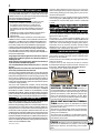
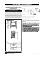
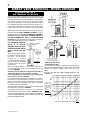
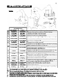
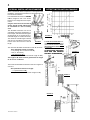
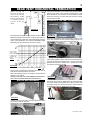
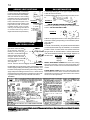
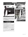
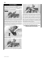
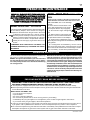
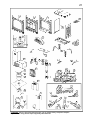
1
CERTIFIED UNDER CANADIAN AND AMERICAN NATIONAL STANDARDS, CSA 2.33, ANSI Z21.88 FOR VENTED GAS FIREPLACE HEATERS
INSTALLATION AND OPERATION INSTRUCTIONS FOR:
VENTED GAS FIREPLACE HEATER
NATURAL GAS MODELS CDVS600-N and
CS600-N
PROPANE GAS MODELS CDVS600-P and CS600-P
Model CS600 is made up of Model CDVS600 and the Adapter Kit GS-150KT
WARNING: If the information in these instructions is not followed exactly, a fire or
explosion may result causing property damage, personal injury or death.
FOR YOUR SAFETY
Do not store or use gasoline or other flammable vapours and liquids in the vicinity of this or any other appliance.
WHAT TO DO IF YOU SMELL GAS:
• Do not try to light any appliance.
• Do not touch any electrical switch.
• Do not use any phone in your build
ing.
• Immediately call your gas supplier
from a neighbour's phone. Follow the
gas supplier's instructions.
• If you cannot reach your gas supplier,
call the fire department.
Installation and service must be performed by a qualified installer, service
agency or the gas supplier.
W415-0162 / E / 03.05.04
2
TABLE of CONTENTS
Pg 2-4
INTRODUCTION
Pg 14
Warranty
General Instructions
General Information
Care of Glass & Plated Parts
Shipping Bracket
5
6-12
GAS INSTALLATION
15-16 FINISHING
LOCATION & CLEARANCES
DIRECT VENT SPECIFICS
MODEL CDVS600
Vent Lengths/Air Terminal Locations
Special Installation Example
Offset Installation Example
Horizontal Terminations
Orifice Replacement
Top Vent to Rear Vent Modification
Venting Parameters
Wall & Ceiling Protection
Horizontal Venting Installation
Vertical Venting Installation
Stove Vent Connection
Mobile Home Installation
13-14 B-VENT SPECIFICS
MODEL CS600
Chimney Installation
'B' Vent Installation
Combustion Air
Adding Vent Sections
Flashing and Storm Collar Installation
Logo Placement
Front Cast Installation
Glass Door Closing & Opening
Log Placement
17-18 OPERATION / MAINTENANCE
Spill Switch
Venting Action Check
Operating Instructions
Maintenance
19
19
BLOWER INSTALLATION
ADJUSTMENTS
Pilot Burner Adjustment
Venturi Adjustments
Restricting Vertical Vents
20-21 REPLACEMENTS
Ordering Replacement Parts
Termination Kits
Replacement Parts
Accessories
22-23 TROUBLE SHOOTING GUIDE
24
SERVICE HISTORY
PLEASE RETAIN THIS MANUAL FOR FUTURE REFERENCE
WARNING
• The stove is a vented gas-fired heater. Do not burn wood or other materials in this stove.
• Adults and especially children should be alerted to the hazards of high surface temperatures and should stay
away to avoid burns or clothing ignition. Supervise young children when they are in the same room as the
stove.
• Due to high temperatures, the stove should be located out of traffic and away from furniture and draperies.
• Clothing or other flammable material should not be placed on or near the stove.
• Any safety screen or guard removed for servicing must be replaced prior to operating the stove.
• It is imperative that the control compartments, burners and circulating blower and its passageway in the
stove and venting system are kept clean. The stove and its venting system should be inspected before use
and at least annually by a qualified service person. More frequent cleaning may be required due to excessive
lint from carpeting, bedding material, etc. The stove area must be kept clear and free from combustible
materials, gasoline and other flammable vapours and liquids.
• Under no circumstances should this stove be modified.
• This stove must not be connected to a chimney flue pipe serving a separate solid fuel burning appliance.
• Do not use this stove if any part has been under water. Immediately call a qualified service technician to
inspect the stove and to replace any part of the control system and any gas control which has been under
water.
• Do not operate the stove with the glass door opened, cracked or broken. Replacement of the glass should be
done by a licensed or qualified service person.
• Do not strike or slam shut the stove glass door.
• This fireplace uses and requires a fast acting thermocouple. Replace only with a fast acting thermocouple
supplied by Wolf Steel Ltd.
NOTE: changes, other than editorial, are denoted by a vertical line in the margin.
W415-0162 / E / 03.05.04
3
CONTINENTAL gas fireplaces are manufactured under the strict Standard of the world recognized
ISO 9001 : 2000 Quality Assurance Certificate.
CONTINENTAL products are designed with superior components and materials, assembled by trained craftsmen
who take great pride in their work. The burner and valve assembly are leak and test-fired at a quality test station.
Once assembled the complete fireplace is thoroughly inspected by a qualified technician before packaging to ensure
that you, the customer, receives the quality product that you expect from WOLF STEEL Ltd..
CONTINENTAL GAS FIREPLACE PRESIDENT'S LIFETIME LIMITED WARRANTY
The following materials and workmanship in your new CONTINENTAL gas fireplace are
warranted against defects for as long as you own the fireplace. This covers: combustion chamber,
heat exchanger, stainless steel burner, phazer™ logs and embers, ceramic glass (thermal breakage
only), gold plated parts against tarnishing, porcelainized enamelled components and aluminium
extrusion trims.
Electrical (110V and millivolt) components and wearable parts such as blowers, gas valves,
thermal switch, switches, wiring, remote controls, igniter, gasketing, and pilot assembly are
covered and WOLF STEEL LTD. will provide replacement parts free of charge during the first
year of the limited warranty.
Any labour related to warranty repair is not covered.
CONDITIONS AND LIMITATIONS
WOLF STEEL LTD. warrants its products against manufacturing defects to the original purchaser only -- i.e., the individual or legal entity (registered customer) whose name appears on
the warranty registration card filed with WOLF STEEL Ltd. -- provided that the purchase was made through an authorized CONTINENTALdealer and is subject to the following conditions and
limitations:
This factory warranty is nontransferable and may not be extended whatsoever by any of our representatives.
The gas fireplace must be installed by a licenced, authorized service technician or contractor. Installation must be done in accordance with the installation instructions included with the
product and all local and national building and fire codes.
This limited warranty does not cover damages caused by misuse, lack of maintenance, accident, alterations, abuse or neglect and parts installed from other manufacturers will nullify this
warranty.
This limited warranty further does not cover any scratches, dents, corrosion or discolouring caused by excessive heat, abrasive and chemical cleaners nor chipping on porcelain enamel
parts, mechanical breakage of PHAZER™ logs and embers, nor any venting components used in the installation of the fireplace.
WOLF STEEL Ltd. warrants its stainless steel burners against defects in workmanship and material for life, subject to the following conditions: During the first 10 years WOLF STEEL Ltd.
will replace or repair the defective parts at our option free of charge. From 10 years to life, WOLF STEEL LTD. will provide replacement burners at 50% of the current retail price.
In the first year only, this warranty extends to the repair or replacement of warranted parts which are defective in material or workmanship provided that the product has been operated in
accordance with the operation instructions and under normal conditions.
After the first year, with respect to this President's Limited Lifetime Warranty, WOLF STEEL LTD. may, at its discretion, fully discharge all obligations with respect to this warranty by refunding
to the original warranted purchaser the wholesale price of any warranted but defective part(s).
WOLF STEEL Ltd. will not be responsible for installation, labour, or any other costs or expenses related to the reinstallation of a warranted part, and such expenses are not covered by this
warranty.
Notwithstanding any provisions contained in this President's Limited Lifetime Warranty, WOLF STEEL’S responsibility under this warranty is defined as above and it shall not in any event
extend to any incidental, consequential or indirect damages.
This warranty defines the obligations and liability of WOLF STEEL Ltd. with respect to the CONTINENTAL gas fireplace and any other warranties expressed or implied with respect to this
product, its components or accessories are excluded.
WOLF STEEL Ltd. neither assumes, nor authorizes any third party to assume, on its behalf, any other liabilities with respect to the sale of this product. WOLF STEEL Ltd. will not be responsible
for: over-firing, downdrafts, spillage caused by environmental conditions such as rooftops, buildings, nearby trees, hills, mountains, inadequate vents or ventilation, excessive venting
configurations, insufficient makeup air, or negative air pressures which may or may not be caused by mechanical systems such as exhaust fans, furnaces, clothes dryers, etc.
Any damages to fireplace, combustion chamber, heat exchanger, brass trim or other component due to water, weather damage, long periods of dampness, condensation, damaging chemicals
or cleaners will not be the responsibility of WOLF STEEL Ltd.
The bill of sale or copy will be required together with a serial number and a model number when making any warranty claims from your authorized dealer. The warranty registration card
must be returned within fourteen days to register the warranty.
WOLF STEEL Ltd. reserves the right to have its representative inspect any product or part thereof prior to honouring any warranty claim.
ALL SPECIFICATIONS AND DESIGNS ARE SUBJECT TO CHANGE WITHOUT PRIOR NOTICE DUE TO ON-GOING PRODUCT IMPROVEMENTS. NAPOLEON® IS A REGISTERED
TRADEMARK OF WOLF STEEL LTD. PATENTS U.S. 5.303.693.801 - CAN. 2.073.411, 2.082.915. © WOLF STEEL LTD.
W415-0162 / E / 03.05.04
4
GENERAL INSTRUCTIONS
THIS GAS STOVE SHOULD BE INSTALLED AND SERVICED
BY A QUALIFIED INSTALLER to conform with local codes.
Installation practices vary from region to region and it is important
to know the specifics that apply to your area,
for example: in Massachusetts State:
• The fireplace damper must be removed or welded in the open
position prior to installation of a fireplace insert or gas log.
• The appliance off valve must be a “T” handle gas cock.
• The flexible connector must not be longer than 36 inches.
• The appliance is not approved for installation in a bedroom or
bathroom unless the unit is a direct vent sealed combustion
product.
• WARNING: This product must be installed by a licensed plumber
or gas fitter when installed within the commonwealth of
Massachusetts.
In absence of local codes, install to the current CAN1-B149
Installation Code in Canada or to the National Fuel Gas Code,
ANSI Z223.1, and NFPA 54 in the United States. Mobile home
installation must conform with local codes. In the absence of
local codes, install to the current standard for gas equipped
mobile housing CAN/CSA Z240 MH Series in Canada or the
manufactured home construction and safety standard, Title 24
CFR, part 3280, or the Fire Safety Criteria for manufactured
home installations, Sites and Community Standard ANSI/NFPA
501A in the United States.
Purge all gas lines with the glass door of the stove removed.
Assure that a continuous gas flow is at the burner before reinstalling the door.
Under extreme vent configurations, allow several minutes (515) for the flame to stabilize after ignition.
It is recommended that all horizontal runs have a ¼ inch rise
per foot.
Objects placed in front of the stove must be kept a minimum
of 48" away from the front face of the unit.
The stove and its individual shutoff valve must be disconnected
from the gas supply piping system during any pressure testing of
that system at test pressures in excess of 1/2 psig (3.5 kPa). The
stove must be isolated from the gas supply piping system by
closing its individual manual shutoff valve during any pressure
testing of the gas supply piping system at test pressures equal to
or less than ½ psig (3.5 kPa).
The stove, when installed with a blower, must be electrically
connected and grounded in accordance with local codes. In the
absence of local codes, use the current CSA C22.1 CANADIAN
ELECTRICAL CODE in Canada or the ANSI/NFPA 70-1996
NATIONAL ELECTRICAL CODE in the United States. The blower
power cord must be connected into a properly grounded receptacle.
The grounding prong must not be removed from the cord plug.
GENERAL INFORMATION
FOR YOUR SATISFACTION, THIS STOVE HAS BEEN TESTFIRED TO ASSURE ITS OPERATION AND QUALITY!
Minimum inlet gas supply pressure is 4.5 inches water column for
natural gas and 11 inches water column for propane. Maximum
inlet gas pressure is 7 inches water column for natural gas and 13
inches water column for propane. When the valve is set to "HI", the
manifold pressure under flow conditions is 3.5 inches water column
for natural gas and 10 inches water column for propane. When the
fireplace is installed at elevations above 4,500ft, and in the absence
of specific recommendations from the local authority having jurisdiction, the certified high altitude input rating shall be reduced at the
rate of 4% for each additional 1,000ft.
W415-0162 / E / 03.05.04
Change in flame appearance from "HI" to "LO" is more evident in natural gas than in propane. Expansion / contraction
noises during heating up and cooling down cycles are normal and to be expected.
This appliance is only for use with the type of gas indicated
on the rating plate. (See page 14). This appliance is not
convertible for use with other gases, unless a certified kit
is used.
INSTALLER: It is your responsiblity to check off the
appropriate box on the rating plate according to the
model, venting and gas type of the unit.
CARE OF GLASS, AND PLATED PARTS
Do not use abrasive cleaners to clean these parts. Buff
lightly with a clean dry cloth.
The glass is 3 /16 " ceramic glass available from your
Continental / Wolf Steel Ltd. dealer. DO NOT SUBSTITUTE
MATERIALS. Clean the glass after the first 10 hours of operation with a recommended gas fireplace glass cleaner.
Thereafter clean as required. DO NOT CLEAN GLASS
WHEN HOT! If the glass is not kept clean permanent discolouration and / or blemishes may result.
SHIPPING BRACKET
To avoid the stove being damaged during shipping, a shipping bracket has been used and must be unbolted before
the stove can be installed.
1. Remove the four nuts holding the shipping bracket to the
bottom of the stove.
2. Lift the stove up and away from the skid to clear the
threaded bolts sticking through the bracket. Set down on a
flat surface. The stove top is not secured to the unit.
3. Discard the nuts, bracket and the skid.
FIGURE 1
4 NUTS
SHIPPING
BRACKET
CDVS600: TOP VENT / REAR VENT
VERTICAL TERMINATION: Maximum input is 35,000 BTU/hr for natural gas and 31,500 BTU/hr
for propane. Maximum output for natural gas is 27,300
BTU/hr at an efficiency of 78%. Maximum output for propane is 24,570 BTU/hr at an efficiency of 78%. Maximum A.F.U.E. (annual fuel utilization efficiency) rating is
72% for natural gas and 71% for propane.
REAR VENT HORIZONTAL TERMINATION: Maximum input is 21,000 BTU/hr for natural
and propane gas. This application requires changing
the main burner orifice.
This stove is not approved for closet or recessed installations. It is approved for bathroom, bedroom and bedsitting room installations.
This stove may be installed in an aftermarket permanently located, manufactured (mobile) home, where not
prohibited by local codes.
CS600:
Maximum input is 35,000 BTU/hr for natural gas and 31,500 BTU/hr for propane. This stove is
approved for bedroom and bed-sitting room installations.
5
LOCATION & CLEARANCES
Provide adequate ventilation and combustion air.
Provide adequate accessibility clearance for servicing
and operating the stove.
Never obstruct the front opening of the stove.
MAINTAIN THESE MINIMUM CLEARANCES TO
COMBUSTIBLES:
CDVS600 AND CS600
As long as clearance to combustibles is kept within the
required distances, the most desirable and beneficial location for a Continental stove is in the centre of a building,
thereby allowing the most efficient use of the heat created.
The location of windows, doors and the traffic flow in the
room where the stove is to be located should be considered. If possible, you should choose a location where the
vent will pass through the house without cutting a floor or
roof joist.
FIGURE 3
A. 6"
B. 6"
C. 2"*
NO ADDITIONAL FLOOR PROTECTION IS REQUIRED
MINIMUM 20" FROM STOVE TOP TO CEILING
6" TO SINGLE WALL CONNECTOR
1" TO DIRECT VENT AND B-VENT
* AT A DISTANCE OF 2" FROM THE WALL, ACCESS TO THE BLOWER
SWITCH, ON -OFF SWITCH OR T H E BLOWER POWER CORD MAY NOT
BE PRACTICAL .
A terminal shall not terminate directly above a
sidewalk or paved driveway which is located
between two single family dwellings and serves
both dwellings. Local codes or regulations may
require different clearances.
Do not allow the inside liner to bunch up on horizontal
or vertical runs and elbows. Keep it pulled tight. A 1-1/
4" air gap all around between the inner liner and outer
stove pipe is required for safe operation. Use a firestop
when penetrating interior walls, floor or ceiling.
FIGURE 2 - SHOWN WITH OPTIONAL FRONT INSTALLED
NOTE: The total width of the stove is increased to 39" width with the
optional side shelves attached.
W415-0162 / E / 03.05.04
6
DIRECT VENT SPECIFICS - MODEL CDVS600
VENTING LENGTHS &
AIR TERMINAL LOCATIONS
Use only Wolf Steel or Simpson Dura-Vent Model DV-GS
venting components. Minimum and maximum vent lengths,
for both horizontal and vertical installations, and air terminal locations for either system are set out in this manual
and must be adhered to. For Simpson Dura-Vent, follow
the installation procedure provided with the venting components. Both Wolf Steel and Simpson Dura-Vent venting
components may have a 0" rise per foot on horizontal runs.
FIGURE 5
When using Wolf Steel venting components, use only the
following vent kits: WALL TERMINAL KIT GD175 (7-1/2' of
venting included), or 1/12 TO 7/12 PITCH ROOF TERMINAL
KIT GD110, 8/12 TO 12/12 ROOF TERMINAL KIT GD111,
FLAT ROOF TERMINAL KIT GD112 or STOVE PERISCOPE
KIT GD180 (for wall penetration below grade) in conjunction with the appropriate venting components.
For optimum performance, it is recommended that all horizontal runs have a minimum ¼ inch rise per
foot.
These vent kits allow for either
horizontal or vertical venting of
the stove. The maximum
number of 4" flexible
connections is two horizontally
FIGURE 4
or three vertically (excluding
the stove and the air terminal
connections).
When terminating vertically, the minimum vertical rise is
34 inches above the stove and the maximum vertical rise
is 40 feet. FIGURE 4.
Deviation from the minimum vertical vent length can create difficulty in burner start-up and/or carboning.
Use an adjustable pipe as the final length of rigid piping
to the stove for ease of installation.
For optimum flame appearance and stove performance,
keep the vent length and number of elbows to a minimum.
The air terminal must remain unobstructed at all times.
Examine the air terminal at least once a year to verify that it
is unobstructed and undamaged.
The maximum horizontal run is 34 inches with a 90 o elbow
located 29" above the stove. FIGURE 5.
The maximum horizontal run with a 57 inch vertical rise
immediately above the stove is 20 feet . FIGURES 6a & b.
IF VERTICAL RISES GREATER THAN 57 INCHES ARE NECESSARY, THE INCREASED RISE MUST BE DEDUCTED FROM THE
MAXIMUM HORIZONTA L RUN.
FIGS6a-b
HORIZONTAL RUN NOT TO
EXCEED VERTICAL RISE
Use the chart on this page to calculate horizontal runs for
vertical rises between 29 and 57 inches. When calculating
maximum run lengths, include 5 feet for each 90° or 45°
elbow.
(DO NOT INCLUDE THE FIRST ELBOW DIRECTLY OFF
THE UNIT.)
REQUIRED
VERTICAL
RISE FROM
FIREPLACE
TO FIRST ELBOW
IN
INCHES
FIGURE 7
CALCULATED HORIZONTAL VENT RUN IN FEET
W415-0162 / E / 03.05.04
7
FIGURE 8
W415-0162 / E / 03.05.04
8
SPECIAL INSTALLATION EXAMPLE
When a horizontal offset is required in a through-the-roof
installation, the following procedure for vent length calculations must be followed:
In an installation as shown in FIGURES
9 & 12, lengths A and C are known
based on room height and roof requirements.
Length C must never be less than 29
inches. Any 90° and 45° elbows must
be calculated as 5 feet of venting
each.
The allowable horizontal run can be
calculated using these parameters. In
this example, the total vertical height is
20 feet (length "A" is required to be 11
feet while length "C" needs to be 9 feet).
The maximum vertical length is 40 feet
and all runs and elbows must be subFIGURE 9
tracted from this maximum vertical
length.
The maximum allowable horizontal run that "B" can be is:
40 ft. (maximum vertical run length)
-11 ft. (through the roof vertical rise "A")
-10 ft. (2 - 90° elbow)
- 9 ft. (vertical run "C")
10 ft. (maximum allowable horizontal length for "B")
OFFSET INSTALLATION EXAMPLE
FIGURE 10
If a first run of 120 inches is required, using the "First Vent Run"
on the chart shows that a maximum second run of 60 inches
is allowable.
IF NECESSARY, THE FIRST
RUN AND THE SECOND
RUN MAY BE REVERSED.
The length of "B" must never be greater than the length
of "A" and "C" combined.
The maximum allowable horizontal run that "A" in Figure 13
can be is:
40 ft. (maximum vertical run length)
- 7 ft. (horizontal run "B")
33 ft. (maximum allowable vertical length for "A")
FIGURE 12
FIGURE 13
W415-0162 / E / 03.05.04
FIGURE 11
9
REAR VENT HORIZONTAL TERMINATION
When venting off
the rear of the unit
and terminating
horizontally, a #45
natural gas orifice
or a #55 propane
orifice must be
used.
Care should be taken not to damage the gas pipe. When
removing the orifice, using a 9/16" socket wrench, a 7/8"
back-up wrench must be used on the manifold, located
below the housing, to ensure that the aluminum tubing
does not twist or kink.
CHANGING A TOP VENT TO A REAR VENT
STOVE TOP
FIGURE 14a
TOP VENT FILLER PLATE
The maximum allowable length is 20 feet. All 90° and 45°
elbows (except the first two when venting horizontally) reduce the length by 5 feet each, both horizontally and vertically). In this illustration, the maximum allowable length
after taking the two elbows into account is 10 feet.
REQUIRED
VERTICAL
RISE FROM
FIREPLACE
TO FIRST ELBOW
IN
INCHES
FIGURE 17a
7" COVER
Unscrew and discard the top vent filler plate. Lift off the cast
stove top. Unscrew the four screws holding both the top
heat shield and the 7" flue collar in place and lift off.
FIGURE 17b
Lift the gasket off. Unscrew the 4 screws securing the 4"
collar and its gasket in place and remove it and the knockout from the rear panel. Remove the 7" and 4" covers and
gaskets from the back. Position the 4" gasket and cover
over the flue opening in the top.
FIGURE 14b
CALCULATED HORIZONTAL VENT RUN IN FEET
Use the chart on this page to calculate horizontal runs for
vertical rises between 29 and 57 inches.
When calculating maximum run lengths, include 5 feet for
each 90° or 45° elbow.
(DO NOT INCLUDE THE FIRST TWO ELBOWS DIRECTLY
OFF THE UNIT WHEN VENTING HORIZONTALLY.)
ORIFICE REPLACEMENT
4" COVER
FIGURE 17c
(FLANGE DOWN)
Secure with 4 screws. Place the 7" gasket and cover over
the air opening in the top. Replace the top heat shield and
re-secure. Secure both gaskets and collars over the rear
openings. Using the 2 screws secure the optional trivet to
the underside of the top. Replace the stove top.
TOP HEAT SHIELD
FIGURE 15
FIGURE 17d
In order to access the orifice, the log support secured by
two screws, must be removed.
FIGURE 16
W415-0162 / E / 03.05.04
10
VENTING PARAMETERS
WALL & CEILING
PROTECTION
FOR SAFE AND PROPER OPERATION OF THE STOVE,
FOLLOW THE VENTING INSTRUCTIONS EXACTLY.
FIGURES 18a-d
OR
FIGURE 19
HORIZONTAL INSTALLATION
CORNER INSTALLATION
W415-0162 / E / 03.05.04
This application occurs when venting through an exterior
wall. Having determined the air terminal location, cut and
frame a hole in an exterior wall with a minimum square or
round opening of 9". (As an alternative to framing, a vent
pipe shield may be installed, ensuring a 1" clearance to
combustibles.)
FOR OPTIMUM PERFORMANCE, THE STOVE PIPE SHOULD RISE
¼" PER FOOT OF RUN.
1. Mark and cut the vent pipe shield to the determined
depth of the combustible wall. Apply a bead of caulking
(not supplied) to the framework or to the shield plate (in the
case of a finished wall) and secure the shield through the
opening to the interior wall. The final location of the vent
pipe shield should maintain the required clearance to the
7" vent pipe. Do not fill this cavity with any type of material.
Apply a bead of caulking all around and place a firestop
spacer over the vent shield to restrict cold air from being
drawn into the room or around the stove. Ensure that both
spacer and shield maintain the required clearance to
combustibles. Once the vent pipe is installed in its final
position, apply sealant between the pipe and the firestop
spacer.
11
VERTICAL INSTALLATION
This application occurs
when venting through a
roof.
FIGURE 20
Installation kits for various roof pitches are
available from your
Continental dealer.
See Accessories to order the specific kit required.
1. Determine the air terminal location and move the stove
into position. Cut and frame 9 inch openings in the ceiling
and the roof to provide the minimum 1 inch clearance between the stove pipe
and any combustible
material. Try to center
the exhaust pipe locaFIGURE 21
tion midway between
two joist to prevent having to cut them. Use a
plumb bob to line up the
center of the openings.
DO NOT FILL THIS SPACE WITH ANYTYPE OF MATERIAL.
A vent pipe shield will prevent any materials such as insulation, from filling up the 1" air space around the pipe. Nail
headers between the joist for extra support.
2. Apply a bead of caulking (not supplied) to the framework or to the Wolf Steel vent pipe shield plate or equivalent (in the case of a finished ceiling), and secure over the
opening in the ceiling. A firestop must be placed on the
bottom of each framed opening in a roof or ceiling that the
venting system passes through. Apply a bead of caulking
all around and place a firestop spacer over the vent shield
to restrict cold air from being drawn into the room or around
the stove. Ensure that both spacer and shield maintain the
required clearance to combustibles. Once the vent pipe is
installed in its final position, apply sealant between the
pipe and the firestop spacer.
3. In the attic, after the pipe
has been installed, slide the
vent pipe collar down to cover
up the open end of the shield
and tighten. This will prevent any
materials, such as insulation,
from filling up the 1" air space
around the pipe.
FIGURE 22
HORIZONTAL VENTING INSTALLATION
FOR SAFE AND PROPER OPERATION OF THE
STOVE, FOLLOW THE VENTING INSTRUCTIONS
EXACTLY.
FOR HORIZONTAL R UNS, BOTH WOLF STEEL AND
SIMPSON DURA-VENT VENTING COMPONENTS MAY
HAVE A 0" RISE PER FOO T.
FOR OPTIMUM PERFORMANCE IT IS RECOMMENDED THAT ALL HORIZONTAL RUNS HAVE A
MINIMUM ¼ INCH RISE PER FOOT.
1. Stretch the 4" diameter aluminum flexible liner to the
required length taking into account the additional length
needed for the finished wall surface.
Spacers are attached to the 4" inner flex liner at predetermined intervals to maintain a 1-1/4" air gap to the 7" outer
stove pipe. These spacers must not be removed.
Slip a 4" diameter length of aluminum flexible liner a minimum of 2" over the inner sleeve of the air terminal. Secure
to the sleeve using 3 screws. Seal the joint and screw
heads using the high temperature sealant provided.
2. Slip the first section of 7" diameter stove pipe a minimum of 2" over the outer sleeve of the air terminal. Secure
to the sleeve using 3 screws. Seal the joint and screw
heads using high temperature sealant.
3. Insert the liners through the firestop / vent pipe shield.
Holding the air terminal (lettering in an upright, readable
position), secure to the exterior wall. Make weather tight by
sealing with caulking (not supplied). The air terminal mounting plate may be recessed (up to 3/4" maximum) into the
exterior wall or siding.
FIGURE 23
FIGURE 24
4. If more than one length of liner needs to be used to
reach the stove, couple them together as illustrated in
FIGURE 24. Seal the joints using the same procedure as
described above.
The vent system must be supported approximately every
10 feet along a horizontal run. Use supports or equivalent
non-combustible strapping to maintain the 1" clearance
from combustibles.
W415-0162 / E / 03.05.04
12
VERTICAL VENTING INSTALLATION
STOVE VENT CONNECTION
1. Fasten the roof
FIGURE 25
support to the roof using the screws provided. The roof support
is optional. In this case
the venting is to be adequately supported using either an alternate
method suitable to the
authority having jurisdiction or the optional
roof support.
2. Slip a 4" diameter length of aluminum flexible liner a
minimum of 2" over the inner sleeve of the air terminal.
FIGURE 26 Secure to the sleeve using 3 screws
and flat washers.Seal the joint and
screw heads using high temperature
sealant. Repeat using a 7" diameter
length of rigid piping.
If the attic space is tight, we recommend adding sufficient lengths
of 7" rigid piping, secured and
sealed as necessary.
1. Attach the adjustable pipe to the last section of rigid
piping. Secure with screws and seal.
2. Install the 4" aluminum flexible liner to the stove. Secure with 3 screws and flat washers. Seal the joint and
screw holes using the high temperature sealant provided.
3. Thread the air terminal pipe assembly down through
the roof support and attach, ensuring that a minimum 16"
of air terminal will penetrate the roof when fastened. The
air terminal must be located vertically and plumb.
4. Remove nails from the shingles, above and to the
sides of the chimney. Place the flashing over the air terminal and slide it underneath the sides and upper edge of the
shingles.
Ensure that the air terminal is properly
centered within the
flashing, giving a 3/4"
margin all around.
Fasten to the roof. Do
NOT nail through the
lower portion of the
flashing.
Make
FIGURE 27
weather-tight by sealing with caulking.
Where possible, cover the sides and top edges of the flashing with roofing material.
5. Apply a heavy bead of waterproof caulking 2 inches above
the flashing.
Slide the storm collar around the air terminal and down to
the caulking. Tighten to ensure that a weather-tight seal
between the air terminal and the collar is achieved. Attach
the other storm collar centered between the air intake and
air exhaust slots onto the air terminal. Tighten securely.
6. Attach the vertical rain cap.
7. In the attic, slide the vent pipe collar down to cover up
the open end of the shield and tighten. This will prevent any
materials, such as insulation, from filling up the 1" air space
around the pipe.
W415-0162 / E / 03.05.04
3. Run a bead of high temperature sealant around the
inside of the air intake collar. Pull the adjustable pipe a
minimum 2" into the air intake collar.
FIGURE 28
ENSURE THAT THE SEALANT IS NOT VISIBLE ON THE
E X T E R I O R P I P E S O N C E I N S T ALL AT I O N I S
COMPLETED. AN OPTIONAL DECORATIVE BRASS
BAND IS AVAILABLE FOR THIS USE. (STANDARD WITH
A GD175 KIT). IN THE EVENT THAT THE VENTING
MUST BE DISASSEMBLED, CARE MUST BE TAKEN TO
RESEAL THE VENTING.
MOBILE HOME INSTALLATION
In Canada, mobile home installation may be vented horizontally or vertically. In the United States, it may only be
installed vertically. See "Vertical Venting" or "Horizontal Air
Terminal Installation" for installation.
For mobile home installations, the fireplace must be fastened in place. It is recommended that the fireplace be
secured in all installations. Use the leveling/securing kit,
GDSLL-KT for this purpose.
CONTINUE WITH "GAS INSTALLATION", PAGE 14
13
B-VENT SPECIFICS - MODEL CS600
CHIMNEY INSTALLATION
THREE TYPES OF
CHIMNEY SYSTEMS
MAY BE USED WITH
THIS STOVE:
Ensure that 2 female ends remain at the top.
Re-secure the access plate.
3. Remove the spill switch bracket from the rear of the
adapter. Unscrew the spill switch and discard the bracket.
Attach the spill switch to the bracket supplied with the stove
and secure onto the adapter.
4. Bring the wires through the lower hole in the adapter. To
pass the wires through the hole more easily, temporarily
tape the two terminals together.
5. With the spill switch opening aligned to the back of the
stove, take hold of the adapter base and push the crimped
edge into the stove flue collar.
6. Connect the upper wire terminals to the spill switch.
FIGURES 29
FIGURE 31
INSTALLING 'B' VENT:
Follow the instructions of the 'B' vent manufacturer for chimney installation.
1. Remove the access plate. Remove and discard the air
intake cover plate located directly behind the access plate.
2. Feed the 2 wires, supplied, through the 7" collar at the
top of the unit; bring them out the air intake opening but
behind the rear panel as shown.
7. Disconnect the wire lead from terminal 3 on the valve
and reconnect to the male end of the spill switch wire. Connect the female end of the spill switch wire to terminal 3 on
the valve.
Leave all excess wire in an orderly manner.
For aesthetics, the adapter has been designed to accept a standard matte black 7" stove pipe and the Continental decorative brass band (standard with the
GS-150KT). Both are available from your Continental
dealer.
B-VENT MODEL CS600 ONLY
Attach the B-Vent label, shown below, in the control area
of the appliance.
THIS FIREPLACE HAS BEEN CONVERTED TO A ‘B’VENT MODEL.
ATTACHEZ CET ETIQUETTE DANS LA REGION DE CONTROLE DU FOYER.
CE FOYER A ETE CONVERTI A UN MODELE A SYSTEME D’EVACUATION ‘B’.
COMBUSTION AIR
A chimney venting this stove shall not vent any solid fuel
burning appliance.
Any stove needs air for safe operation and must be installed in such a way that adequate combustion air is
available.
FIGURE 30
W415-0162 / E / 03.05.04
14
ADDING VENT SECTIONS
For ease of assembly, a 7" telescoping stove pipe may be installed over
the 4" vent connection of the adapter.
Add vent sections, twist locking
(clockwise) securely, to the required
height. The vent should extend, at
least, 3 feet above its point of contact with the roof and, at least, 2 feet
higher than any wall, roof or building within 10 feet. (This is a guideline only; local venting codes should
be followed which may differ in
height and clearance requirements.)
GAS INSTALLATION
1. Install rigid black pipe, or 1/2" type L copper tubing with
a shut-off valve to the stove.
2. Seal and tighten the gas line securely to the flex connector.
FIGURE 32
DO NOT KINK FLEXIBLE CONNECTOR.
3. Check for gas leaks by brushing on a soap and water
solution. DO NOT USE OPEN FLAME.
FIGURE 35
4. Mark the appropriate boxes on the rating plate label to
indicate the model type depending on the installation (direct
vent or B-vent).
Figure 36.
INSTALLING FLASHING
AND STORM COLLAR
For ease of accessibility, an optional remote wall switch
or millivolt thermostat may be installed in a convenient
location. Route 2 strand solid core millivolt wire from
the gas stove to the wall switch / millivolt thermostat.
The recommended maximum lead length depends on
WIRE SIZE
MAX. LENGTH
the wire size:
Remove nails from the shingles above and to the sides
of the chimney. Place the
flashing over the vent pipe
and slide it underneath the
sides and upper edge of the
shingles. Ensure that the
vent pipe is properly centered
within the flashing, giving a
3/4" margin all
around. Fasten to the roof on the top and sides.
FIGURE 34
14gauge
16gauge
18gauge
FIGURE 33
DO NOT NAIL through the lower portion of the flashing. Make
weather-tight by sealing with caulking. Where possible, cover
the sides and top edges of the flashing with roofing material.
Apply waterproof caulking around the vent, 1" above the top
of the flashing and push the storm collar down into the caulking. Attach a rain cap to the top of the last vent section.
FIGURE 36
100 feet
60 feet
40 feet
DIRECT VENT MODEL CDVS600: Disconnect the existing
wires from terminals 1 and 3 (from the on/off switch) and
replace with the leads from the wall switch/millivolt thermostat.
B-VENT MODEL CS600: Disconnect the spill switch wire
from terminal 3 on the valve. Connect one lead from the
thermostat to terminal 3 on the valve and the other lead to
the wire from the spill switch.
INSTALLER: It is your responsiblity to check off the appropriate box on the rating plate according to the model,
venting and gas type of the unit.
W415-0162 / E / 03.05.04
15
FINISHING
LOGO PLACEMENT
Remove the backing of the logo supplied and centre over
the logo installation holes, as indicated.
FIGURE 37
TOP
FIGURE 38b
FIGURE 38c
HANDLE
LOGO
RETAINER
FRONT CAST INSTALLATION
1. Lift the top casting off the unit.
2. Fit the securing bolts on the cast front into each of the
respective retainer brackets (located at either side on the
top SEE FIGURE 37b). Insert and tighten the securing screw
from the bottom up (located at the lower center behind the
cast front SEE FIGURE 37a). This will hold the cast front in
place. Replace the top casting.
3. To remove the front, repeat in reverse order.
'T' LATCH
FRONT
RIDGE
RETURN FLANGE
FIGURE 38d
GLASS DOOR INSTALLATION
AND REMOVAL
When installing the glass door, a simple procedure must
be followed in order to not damage the door.
1. Lift the top casting off.
2. Undo the securing screw (located at the lower center of
the cast front) holding the cast front in place. Figure 37a.
3. Lift the cast front out of its retainers (located at either
side on the top). Figure 37b.
4. Open the valve control cover. Pull the latch handles forward
to release. Figure 37c. The door may now be safely removed
by swinging the bottom out and lifting it off. To install the door,
repeat in reverse order.
The return flange must fit over the top of the ridge
so that it rests on top of the firebox. F i g u r e 3 7 d .
The 'T' latch portion is threaded and can be loosened or tightened to adjust for an effective door seal.
Care must be taken when re-installing the door to
ensure that the gasket at the top of the door does
not bunch.
W415-0162 / E / 03.05.04
16
LOG PLACEMENT
Blocked burner ports can cause an incorrect flame pattern,
carbon deposits and delayed ignition. PHAZERT M logs glow
when exposed to direct flame and provide a unique and
realistic glowing effect. Use only certified PHAZERT M logs
available from your Continental dealer.
FIGURE 39a-d
7
1
4
3
2
Place log #1 onto the burner, centering it onto the burner
tray and pushing it as close to the rear wall of the firebox as
possible. Move logs # 2 and 3 into position, lining up the
studs located on the burner with the holes on the bottom of
the logs. Sit the notch at the bottom of log #4 against the
left outermost grate post and position the top of the log into
the pocket provided on the rear log (#1).
5
The notch in log #5 should be pressed down onto the
skewering pin located at the end of the grate as shown to
prevent it from rocking.
6
Position the notch located in log #6 against the grate post.
W415-0162 / E / 03.05.04
Place the bottom of log #7 against the right outermost grate
post and the top into the pocket provided on the center log
(#6). Bend up the tab in the log support to cradle log #7.
Tear the glowing embers into pieces and place onto the
front of the burner. Care should be taken to shred the embers into thin, small irregular pieces as only the exposed
edges of the fibre hairs will glow when exposed to direct
flame; however care should be taken to not block the burner
ports. Blocked ports can cause an incorrect flame pattern,
carbon deposits and delayed ignition.
Log colours may vary. During the initial use of the fireplace,
the colours will become more uniform as colour pigments
burn in during the heat activated curing process.
POSITIONING THE LOGS IMPROPERLY WILL CAUSE
FLAME IMPINGEMENT AND CARBONING.
17
OPERATION / MAINTENANCE
PURGE ALL GAS LINES WITH THE GLASS DOOR
OPEN. ASSURE THAT A CONTINUOUS GAS FLOW
IS AT THE B URNER BEFORE CLOSING THE DOOR.
ALLOW SEVERAL MINUTES (5-15) FOR THE
FLAME TO STABILIZE AFTER IGNITION.
MODEL CS600 ONLY: SPILL SWITCH
This is a thermally activated switch, attached to the back
of the chimney adapter, which senses the change in
temperature and shuts down the gas valve in the event
of a blocked or disconnected vent. It acts as a safety
shut-off to prevent a build up of carbon monoxide or an
explosion of unburnt gases during start up. If the flue
is blocked or has no "draw", the spill switch will automatically shut off the supply of gas within about 5-10
minutes.
TAMPERING WITH THE SWITCH CAN RESULT IN
CARBON MONOXIDE (CO) POISONING AND POSSIBLE DEATH.
MODEL CS600 ONLY: VENTING
ACTION
CHECK
A CHECK FOR CORRECT VENTING ACTION MUST BE
MADE BEFORE THE INSTALLED STOVE IS LEFT WITH
THE CUSTOMER. Test in the following
manner:
1. Close all doors and windows in the
room / start exhaust fans in the home /
turn fireplace blower off (if equipped).
2. Set controls to "high" and light the
unit.
3. Wait 5 minutes. Light a match and
extend it 1" into the hole located above
the spill switch bracket on the adapter.
FIGURE 40
4. Venting action is satisfactory if the
flame stays lit. Venting action is unsatisfactory if the flame
extinguishes.
5. If venting action is unsatisfactory, turn the unit off,
wait 10 minutes and try again. If the match does not stay
lit, turn the unit off and check for vent blockage or restriction. If necessary, consult with a qualified inspector.
OPERATING INSTRUCTIONS
The on-off switch is located on the back of the unit at the top
left corner on models CDVS600 and CS600.
NOTE: The upper firebox baffle of your new cast stove
has intentionally been left unpainted. Its shiny appearance will quickly transform to a dull black finish during
the curing process.
When lit for the first time, the fireplace will emit a slight
odour for a few hours. This is a normal temporary condition caused by the curing of the logs and the "burn-in" of
internal paints and lubricants used in the manufacturing
process and will not occur again. Simply open a window
to sufficiently ventilate the room. After extended periods
of non-operation such as following a vacation or a warm
weather season, the fireplace may emit a slight odour for
a few hours. This is caused by dust particles in the heat
exchanger burning off. Open a window to sufficiently ventilate the room.
OPERATING INSTRUCTIONS
FOR YOUR SAFETY READ BEFORE OPERATING
WARNING: IF YOU DO NOT FOLLOW THESE INSTRUCTIONS EXACTLY, A FIRE OR EXPLOSION
MAY RESULT CAUSING PROPERTY DAMAGE, PERSONAL INJURY OR LOSS OF LIFE.
A. This fireplace is equipped with a pilot which must be lit by hand while following these instructions exactly.
B. Before operating smell all around the fireplace area for gas and next to the floor because some gas is heavier than
air and will settle on the floor.
WHAT TO DO IF YOU SMELL GAS:
• Turn off all gas to the fireplace.
• Open windows.
• Do not try to light any appliance.
• Do not touch any electric switch; do not use any phone in your building.
• Immediately call your gas supplier from a neighbour's phone. Follow the gas supplier's instructions.
• If you cannot reach your gas supplier, call the fire department.
C. Use only your hand to push in or turn the gas control knob. Never use tools. If the knob will not turn by hand, do not
try to repair it. Call a qualified service technician. Force or attempted repair may result in a fire or explosion.
D. Do not use this fireplace if any part has been under water. Immediately call a qualified service technician to inspect
the fireplace and replace any part of the control system and any gas control which has been under water.
W415-0162 / E / 03.05.04
18
LIGHTING INSTRUCTIONS
WARNING: The gas valve has an interlock device which will not allow the pilot burner to be lit until the thermocouple has cooled. Allow approximately 60 seconds for the thermocouple to cool before attempting to re-light.
When lighting and re-lighting, the gas knob cannot be turned from PILOT to OFF unless the knob is depressed.
1. STOP! Read the safety information on the operating
label.
2. Turn off all electric power to the fireplace.
to off.
3. Turn the gas knob clockwise
4. Wait five (5) minutes to clear out any gas. If you smell
gas including near the floor, STOP! Follow "B" on the operating label. If you don't smell gas go to the next step.
ON
O
LO
FF
PL T
IH
O I
5. Find pilot located in front of the back log.
to pilot.
6. Turn gas knob counter-clockwise
7. Depress and hold the gas knob while lighting the pilot
with the push button ignitor. Keep knob fully depressed
for one minute, then release. If the pilot does not continue to burn, repeat steps 3 through 6.
8. With the pilot lit, turn the gas knob counter-clockwise
to on.
9. If equipped with a remote ON-OFF switch, main burner
may not come on when you turn the valve to ON. The
remote switch must be in the ON position to ignite the
burner.
10. Turn on all electric power to the fireplace.
PI LOT
TO TURN OFF GAS
1. Turn off all electric power to the fireplace if service is to
be performed.
2. Push in gas control knob slightly and turn clockto off. Do not force.
wise
MAINTENANCE
TURN OFF THE GAS AND UNPLUG ELECTRICAL POWER
BEFORE SERVICING THE STOVE!
CAUTION: Label all wires prior to disconnection when servicing controls. Wiring errors can cause improper and dangerous operation. Verify proper operation after servicing.
This stove and its venting system should be inspected
before use and at least annually by a qualified service person. The fireplace area must be kept clear and free of combustible materials, gasoline or other flammable vapours
and liquids. The flow of combustion and ventilation air must
not be obstructed.
1. In order to properly clean the burner and pilot assembly, remove the logs exposing both assemblies.
2. Keep the control compartment, logs, burner, air shutter opening and the area surrounding the logs clean by
vacuuming or brushing, at least once a year.
W415-0162 / E / 03.05.04
3. Check to see that all burner ports are burning. Clean
out any of the ports which may not be burning or are not
burning properly.
4. Check to see that the pilot flames are large enough to
engulf the thermocouple and the thermopile on one leg
and reaches toward the burner on the other leg.
5. Replace the cleaned logs.
6. Check to see that the main burner ignites completely
on all openings when the gas knob for the burner is turned
on. A 5-10 second total light-up period is satisfactory. If
ignition takes longer, consult your Continental dealer/distributor.
7. Check that the door gasketing is not broken or missing. Replace if necessary.
19
BLOWER
INSTALLATION
1. Ensure that the access cover plate has been installed.
For location, see Figure 30.
2. Remove the on/off switch bracket and the cover plate
below it. The switch spacers and cover plate may now be
discarded.
3. Decide which side of the blower housing you prefer the
on/off switch to be located on.
Drywall dust will penetrate into blower bearings causing
irrepairable damage and must be prevented from coming
into contact with the blower or its compartment.
Any damage resulting from this condition is not covered by
the warranty policy.
ADJUSTMENTS
PILOT BURNER ADJUSTMENT
Adjust the pilot screw to provide properly sized flame. Turn
in a clockwise direction to reduce the gas flow.
INLET PRESSURE
TAP
MANIFOLD TAP
FIGURE 43
O
LO
ON
FF
P L T
IH
O I
P I L OT
SLOT
PILOT SCREW
FIGURE 44
REMOVED SCREWS
FIGURE 41
4. Remove the 2 screws from the top outer edge of the rear
stove panel. The housing is mounted using these two
holes, as well as two other holes located in the rear panel.
using the same screw holes for one side of the housing.
5. Mount and secure the blower housing using 4 screws.
Ensure that the on/off switch wires pass through the appropriate slot located on either side of the blower housing.
6. Remove the 2 screws from the side of the blower housing that you want the switch to be located on and resecure
the on/off switch.
Because the blower is thermally activated, when turned
on, it will automatically start approximately 15-30 minutes after lighting the stove and will run for approximately
30-45 minutes after the stove has been turned off. Use
of the fan increases the output of heat.
VENTURI ADJUSTMENT
Remove the 2 screws securing the log support bracket.
Natural gas models have air shutters set to 0.375" open
(3/8"). Propane models have air shutters set to 0.313" open
(5/16"). Closing the air shutter will cause a more yellow
flame, but can lead to carboning. The flame may not appear yellow immediately; allow 15 to 30 minutes for the
final flame colour to be established. After making adjustments replace the log support bracket.
FIGURE 45
Air shutter adjustment must only be
done by a qualified gas installer!
RESTRICTING VERTICAL VENTS
FIGURE 42
Vertical installations may display a very active flame. If this
appearance is not desirable, the vent exit must be restricted
using the restrictor vent kit, GDSRP-KT. This will reduce
the velocity of the exhaust gases, slowing down the flame
pattern and creating a more traditional gentle appearance.
Specific instructions are included with the kit.
W415-0162 / E / 03.05.04
20
REPLACEMENTS
Contact your dealer for questions concerning prices and
availability of replacement parts. Normally all parts can be
ordered through your Continental dealer or distributor.
When ordering replacement parts always give the following information:
1.
2.
3.
4.
5.
FOR WARRANTYREPLACEMENTPARTS, A PHOTOCOPYOF THE
MODEL & SERIAL NUMBER OF FIREPLACE
INSTALLATION DATE OF FIREPLACE
PART NUMBER
D ESCRIPTION O F PART
F INISH
* IDENTIFIES ITEMS WHICH ARE NOT ILLUSTRATED. FOR
FURTHER INFORMATION, CONTACT YOUR CONTINENTAL
ORIGINAL INVOICE WILL BE REQUIREDTO HONOUR THE CLAIM.
DEALER.
ROOF TERMINAL KITS
COMPONENTS COMMON TO BOTH UNITS:
#
PART #
DESCRIPTION
1
2
3
4
5
6
7
8
9
9
10
11
11
11
11
12
12
13
13
14
15
16*
17
18*
19*
20*
21*
22
23*
24
25*
26
27
28
29
30
31
W135-0209
W135-0082
W135-0076
W135-0210
W135-0211
W135-0212
W135-0213
GL-646
W725-0035
W725-0026
W010-0624
W455-0058
W455-0059
W455-0065
W455-0050
W010-0800
W010-0801
W455-0069
W455-0067
W680-0005
W680-0004
W290-0029
W357-0001
W361-0016
W550-0001
W573-0008
W385-0131
W390-0001
W660-0009
W690-0002
W380-0002
KB-35
GZ-552
W135-0069_
W135-0073_
W135-0068_
W135-0074
LOG #1
CHARCOAL PIECE (LOG #2)
LOG #3
LOG #4
LOG #5
LOG #6
LOG #7
LOG SET
SIT VALVE - NG
SIT VALVE - LP
BURNER
#35 BURNER ORIFICE - NG
#53 BURNER ORIFICE - LP
#45 BURNER ORIFICE - NG
#55 BURNER ORIFICE - LP
PILOT ASSEMBLY - NG
PILOT ASSEMBLY - LP
PILOT INJECTOR - NG
PILOT INJECTOR - LP
THERMOCOUPLE
THERMOPILE
PILOT GASKET
PIEZO IGNITOR
GLOWING EMBERS
CHARCOAL EMBERS
HIGH TEMPERATURE SEALANT
CONTINENTAL LOGO
LATCH
ON/OFF SWITCH
THERMODISC
VARIABLE SPEED SWITCH KNOB
VARIABLE SPEED SWITCH
REPLACEMENT BLOWER
SIDE (LEFT OR RIGHT)
TOP
LEG EA .
BASE PAINT FINISH ONLY
32
33
34
W010-0459
W660-0006
W080-0405
CS600 COMPONENTS
ADAPTOR C/ W SPILL SWITCH
SPILL SWITCH
SPILL SWITCH BRACKET
TERMINAL KITS
GD110 - 1/12 TO 7/12 PITCH
46
47
48
49
50
W010-0569
W120-0036
W010-0567
W170-0063
W263-0054
AIR TERMINAL
VERTICAL CAP
ROOF SUPPORT
STORM COLLAR
ROOF FLASHING
GD111 - 8/12 TO 12/12 PITCH
46
47
48
49
50
W010-0569
W120-0036
W010-0567
W170-0063
W263-0055
AIR TERMINAL
VERTICAL CAP
ROOF SUPPORT
STORM COLLAR
ROOF FLASHING
GD112 - FLAT ROOF
46
47
48
49
50
W010-0569
W120-0036
W010-0567
W263-0056
W170-0063
AIR TERMINAL
VERTICAL CAP
ROOF SUPPORT
ROOF FLASHING
STORM COLLAR
51*
52*
52*
53*
54*
55
55
55
56*
57
58*
59
60
61
62*
62*
63*
64
W690-0001
W690-0010
W690-0011
W300-0041
W562-0031
GS830-G
GS830-K
GS830-C
GDSLL-KT
GS-64KT
GDS-786KT
F_A**
F_E**
F_P**
W175-0138
W175-0139
BM6745
GD-301
MILLIVOLT THERMOSTAT
REMOTE CONTROL - ADVANTAGE
REMOTE CONTROL - ADVANTAGE
WINDOW GLASS
GLASS GASKET
GOLD TRIVET
BLACK TRIVET
CHROME TRIVET
LEVELING / SECURING KIT
BLOWER KIT
DECORATIVE BRICK PANEL
ART DECO FRONT
EARLY AMERICAN FRONT
PANORAMIC FRONT
CONVERSION KIT - NG-LP
CONVERSION KIT - LP-NG
45° ELBOW
HEAT GUARD
65*
45
66*
W175-0001
GD-201
GDSRP-KT
4" COUPLER
PERISCOPE
RESTRICTOR KIT
67
44
GS-150KT
W025-0001
ADAPTOR KIT
DECORATIVE BRASS BAND
ACCESSORIES:
CDVS600 ACCESSORIES
35 GD175 - WALL TERMINAL KIT
36
37
38
39
40
41
42
43
44
BM6790
GD222
BM67ADJ
W500-0077
W020-0032
BRTC7
BM6724
W010-0300
W025-0001
90° ELBOW - 7" DIAMETER
TERMINAL ASSEMBLY
30" TO 53" ADJUSTABLE PIPE - 7" DIA
FIREST OP / WALL PLATE
HARDWARE
BRASS TRIM COLLAR
24" STOVE PIPE - 7" DIAMETER
10' ALUMINUM FLEX LINER C/ W SPACERS - 4" DIA
DECORATIVE BRASS BAND
PLUS
CS600 ACCESSORIES
46 GD180 - PERISCOPE TERMINAL KIT
36
45
38
49
40
41
42
43
44
BM6790
GD201
BM67ADJ
W500-0077
W020-0032
BRTC7
BM6724
W010-0300
W025-0001
W415-0162 / E / 03.05.04
90° ELBOW - 7" DIAMETER
PERISCOPE
30" TO 53" ADJUSTABLE PIPE - 7" DIA
FIREST OP / WALL PLATE
HARDWARE
BRASS TRIM COLLAR
24" STOVE PIPE - 7" DIAMETER
10' ALUMINUM FLEX LINER C/ W SPACERS - 4" DIA
DECORATIVE BRASS BAND
** FOR AVAILABLE
NUMBER:
PORCELAIN COLOURS, ADD THESE LETTERS T O THE BASE PART
BLUE
BLACK
GREEN
-
B
K
F
BROWN
ALMOND
-
N
S
21
* WARNING: This is a fast acting thermocouple. It is an integral safety component. Replace
only with a fast acting thermocouple supplied by Wolf Steel Ltd.
W415-0162 / E / 03.05.04
22
TROUBLE SHOOTING GUIDE
BEFORE ATTEMPTING TO TROUBLESHOOT, PURGE YOUR UNIT AND INITIALLY LIGHT THE PILOT
SYMPTOM
Pilot will not light.
PROBLEM
No spark at pilot burner
Spark gap is incorrect
No gas at the pilot burner
AND THE MAIN BURNER WITH THE GLASS DOOR REMOVED.
TEST SOLUTION
- check if pilot can be lit by a match
- check that the wire is connected to the push button ignitor.
- check if the push button ignitor needs tightening.
- replace the wire if the wire insulation is broken or frayed.
- replace the electrode if the ceramic insulator is cracked or
broken.
- spark gap should be 0.150" to 0.175" (5/32" to 11/64" approx.)
from the electrode tip and the pilot burner. To ensure proper
electrode location, tighten securing nut (finger tight plus 1/4
turn).
- check that the manual valve is turned on.
- check the pilot orifice for blockage.
- replace the valve.
- call the gas distributor.
Out of propane gas.
- fill the tank.
System is not correctly purged.
- purge the gas line with the stove door open.
Out of propane gas
- fill the tank.
Pilot flame is not large enough
- turn up the pilot flame.
Pilot flame is not engulfing the
thermocouple.
Thermocouple shorting.
-
Faultly thermocouple.
- replace.
Faulty valve.
- replace.
Main burner orifice is plugged.
- remove stoppage in orifice.
Faulty thermopile.
Faulty themostat or switch.
- replace.
- connect a jumper wire across the wall switch terminals; if
main burner lights, replace thermostat.
- disconnect switch wires from the valve & connect a jumper
wire across terminals 1 & 3; if the main burner lights, check the
wires for defects and / or replace wires.
Faulty valve.
- replace.
Pilot goes out while
standing;
Main
burner is in 'OFF'
position.
Gas piping is undersized.
- turn on all gas appliances and see if pilot flame flutters,
diminishes or extinguishes, especially when main burner ignites. Monitor supply pressure.
- check if supply piping size is to code. Correct all undersized
piping.
Main burner goes
out; pilot stays on.
Pilot flame is not large enough
or not engulfing the thermopile.
- turn up pilot flame.
- replace pilot assembly.
Thermopile shorting
Remote wall switch wire is too
long, too much resistance in
the system
Faulty thermostat or switch
MODEL CS600 ONLY:
Venting is spilling
- clean thermopile and thermopile connection to valve.
Pilot goes out when
the gas knob is released.
Pilot burning; no
gas
to
main
burner; gas knob
is on 'HI'; wall
switch / thermostat
is on.
W415-0162 / E / 03.05.04
turn up pilot flame.
replace pilot assembly.
loosen and tighten thermocouple.
clean thermocouple and valve connection.
replace thermocouple.
replace valve.
- shorten wire to correct length or wire gauge.
- replace
- test with spill switch bypassed. Replace if defective.
- check for vent blockage.
23
SYMPTOM
Main burner goes out;
pilot goes out.
PROBLEM
TEST SOLUTION
REFER TO "MAIN BURNER GOES OUT; PILOT STAYS ON"
Vent re-circulating
(MODEL CDVS600 ONLY)
Thermocouple shorting or
- check joint seals and installation.
- loosen and tighten thermocouple
- clean thermocouple and valve connection.
- replace thermocouple.
- replace valve.
Exhaust
fumes
smelled in room,
headaches.
Fireplace is spilling.
- check all seals.
Carbon is being deposited on glass, logs
or combustion chamber surfaces.
Air shutter has become
blocked
- ensure air shutter opening is free of lint or other obstructions.
Flame is impinging on the
logs or combustion chamber.
- check that the logs are correctly positioned.
- open air shutter to increase the primary air.
- check the input rate: check the manifold pressure and orifice
size as specified by the rating plate values.
- check that the door gasketing is not broken or missing and
that the seal is tight.
- check that both vent liners are free of holes and well sealed at
all joints.
- check that minimum rise per foot has been adhered to for any
horizontal venting.
Flames are very
aggressive.(CDVS600
REAR VENT VERTICAL TERMINATION)
Door is ajar
- tighten door clamps
Venting action is too great.
- restrict vent exit with restrictor vent kit, GDSRP-KT.
Blockage in vent.
- remove blockage. In really cold conditions, ice buildup may
occur on the terminal and should be removed as required.
Incorrect installation (vertical
termination only).
- refer to Figure 27 to ensure correct location of storm collars.
Sulphur from fuel is being deposited on glass, logs or combustion chamber surfaces.
- clean the glass with a recommended gas fireplace glass
cleaner. DO NOT CLEAN GLASS WHEN HOT.
If deposits are not cleaned off regularly, the glass may become permanently marked.
MODEL CDVS600
ONLY:
Main burner flame is
a blue, lazy, transparent flame.
White / grey film forms.
W415-0162 / E / 03.05.04
24
W415-0162 / E / 03.05.04