1
LA30 N /LA30 W Companion Printer
TM
User Guide
Order Number: EK-LA30E-UG-001
*1 Cover (1)-UG
1
28/05/96, 13:58
*1 Cover (1)-UG
2
28/05/96, 13:58
LA30N/LA30W Companion Printer
User Guide
Digital Equipment Corporation
Maynard, Massachusetts
#00_0 Title Page (2)
1
23/05/96, 14:09
#00_0 Title Page (2)
2
23/05/96, 14:09
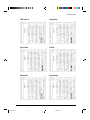
Table of Contents
Preface .................................................................................................... vii
About This Guide ............................................................................................................... vii
Printer Models and Options ............................................................................................... vii
Organization ....................................................................................................................... viii
The LA30N and LA30W Model Specifications ....................................................... viii
Notes, Cautions and Warnings ........................................................................................... ix
1. Introduction ........................................................................................ 1-1
Features .............................................................................................................................. 1-1
Options ............................................................................................................................... 1-2
2. Paper Handling ................................................................................... 2-1
Getting to Know the Printer’s Major Parts and the Control Panel ................................... 2-1
Parts of the Printer ..................................................................................................... 2-2
Operations of the Control Panel ................................................................................ 2-4
Selecting Paper .................................................................................................................. 2-7
Overview of Paper Operations .......................................................................................... 2-8
Adjusting for Paper Thickness .......................................................................................... 2-10
Using Single Sheets ........................................................................................................... 2-11
Loading a Single Sheet of Paper ............................................................................... 2-11
Ejecting Single Sheets ............................................................................................... 2-13
Using Continuous Forms ................................................................................................... 2-14
Positioning the Paper Stack ....................................................................................... 2-15
Loading Continuous Forms (Push Tractor and Rear Feed) ...................................... 2-16
Loading Continuous Forms (Pull Tractor and Bottom Feed) ................................... 2-19
Unloading Continuous Forms (Push-Feed Mode) .................................................... 2-24
Tearing Off Continuous Forms ................................................................................. 2-24
Feeding and Positioning Paper .......................................................................................... 2-26
Print Area Definition ................................................................................................. 2-26
Line Feed/Form Feed ................................................................................................ 2-28
Top-of-Form Adjustment ........................................................................................... 2-28
Switching Paper Types ....................................................................................................... 2-29
Switching from Continuous Forms to Single Sheets (Push-Feed Mode) ................. 2-30
Switching from Single Sheets to Continuous Forms (Push-Feed Mode) ................. 2-30
Switching between Push-Feed and Pull-Feed ........................................................... 2-31
Tips on Paper Handling ..................................................................................................... 2-32
General Tips .............................................................................................................. 2-32
Multipart Forms ......................................................................................................... 2-32
Envelopes .................................................................................................................. 2-32
Labels ........................................................................................................................ 2-32
iii
#00_2 TOC (2)
3
24/05/96, 10:57
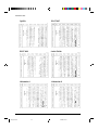
3. Printing ................................................................................................ 3-1
Selecting Print Features .....................................................................................................
Using Commercial Software .....................................................................................
Using the Control Panel ............................................................................................
Selecting Macro 1 or Macro 2 ..........................................................................
Switching Macros and Selecting Features on the Control Panel .....................
Selecting a Resident Font .................................................................................
Changing the Protocol ......................................................................................
Starting or Stopping Printing .............................................................................................
Starting Printing ........................................................................................................
Stopping and Viewing Printing .................................................................................
Resuming Printing .....................................................................................................
Resuming from a Paper-Out ......................................................................................
Removing Printed Pages ....................................................................................................
Removing Single Sheets ...........................................................................................
Removing Continuous Forms ...................................................................................
3-1
3-2
3-2
3-3
3-4
3-7
3-8
3-9
3-9
3-9
3-9
3-9
3-10
3-10
3-10
4. Using Set-Up Mode ............................................................................ 4-1
What is Set-Up Mode for? .................................................................................................
How Set-Up Works ............................................................................................................
Entering the Set-Up Mode .................................................................................................
Overview of the Set-Up Mode ...........................................................................................
Set-Up Mode Functions ............................................................................................
Points to Remember ..................................................................................................
Printing the Printer Configuration .....................................................................................
Deciding Which Options to Change ..................................................................................
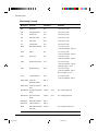
Changing Macro 1 and Macro 2 Options ..........................................................................
Macro 1 and Macro 2 Options List ....................................................................................
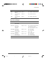
Changing Install Options ...................................................................................................
Install Options List ............................................................................................................
Adjusting Top-of-Form Origin ..........................................................................................
Changing Menu Access Options ........................................................................................
Exiting and Saving .............................................................................................................
Recalling Factory Settings .................................................................................................
Using the Diagnostic Functions .........................................................................................
Printing Test ...............................................................................................................
Hex Dump Mode .......................................................................................................
Set-Up Mode Quick Reference ..........................................................................................
iv
#00_2 TOC (2)
4
24/05/96, 10:57
4-1
4-2
4-2
4-5
4-5
4-11
4-11
4-13
4-14
4-15
4-25
4-25
4-29
4-30
4-30
4-31
4-31
4-31
4-32
4-34
5. Maintenance........................................................................................ 5-1
Cleaning .............................................................................................................................
Cleaning and Vacuuming the Printer ........................................................................
Cleaning the Platen and Paper Bail Rollers ..............................................................
Cleaning the Print Head ............................................................................................
Replacing the Ribbon Cartridge ........................................................................................
Replacing the Print Head ...................................................................................................
5-1
5-1
5-2
5-3
5-3
5-5
6. Trouble-Shooting ................................................................................ 6-1
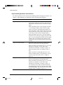
Solving Problems ...............................................................................................................
Print Quality Problems and Solutions .......................................................................
Paper Handling Problems and Solutions...................................................................
Operating Problems and Solutions ............................................................................
Printer Failures ..........................................................................................................
Diagnostic Functions .........................................................................................................
Checking Vertical Alignment .............................................................................................
6-1
6-1
6-4
6-5
6-6
6-6
6-7
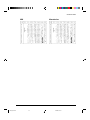
A. Supplies and Options ........................................................................ A-1
Supplies ..............................................................................................................................
Options ...............................................................................................................................
Documentation ...................................................................................................................
Installing Options ...............................................................................................................
Installing the Color Kit ..............................................................................................
A-1
A-1
A-1
A-2
A-2
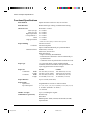
B. Printer and Paper Specifications ..................................................... B-1
Physical Specifications ......................................................................................................
Functional Specifications ...................................................................................................
Performance Specifications ...............................................................................................
Paper Specifications ...........................................................................................................
Print Area ...................................................................................................................
Paper Thickness .........................................................................................................
B-1
B-2
B-4
B-5
B-5
B-7
C. Command Sets................................................................................... C-1
DEC PPL2 Quick Reference Guide................................................................................... C-2
IBM Proprinter X24E and XL24E Quick Reference Guide ............................................. C-22
Epson ESC/P2 Quick Reference Guide ............................................................................. C-26
D. Interface Information ......................................................................... D-1
Parallel Interface ................................................................................................................
Serial Interface ...................................................................................................................
Serial Options ............................................................................................................
Cable Wiring ..............................................................................................................
Buffer Control ...........................................................................................................
D-1
D-4
D-5
D-5
D-5
v
#00_2 TOC (2)
5
24/05/96, 10:57
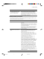
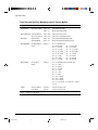
E. Character Sets.................................................................................... E-1
DEC PPL2 Protocol ........................................................................................................... E-1
Common to IBM Proprinter X24E and XL24E Protocol and Epson ESC/P2 Protocol ... E-18
Default Sets ............................................................................................................... E-18
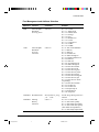
IBM Proprinter X24E and XL24E Protocol ...................................................................... E-24
IBM Set 1/2 ............................................................................................................... E-24
Epson ESC/P2 Protocol ..................................................................................................... E-25
National Character Sets ............................................................................................. E-25
F. Resident Fonts.................................................................................
F-1
Glossary ............................................................................................... GL-1
Index ..................................................................................................... IN-1
vi
#00_2 TOC (2)
6
24/05/96, 10:57
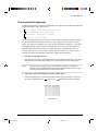
Preface
About this Guide
Thank you for buying a Digital LA30 Companion Printer. You can expect years of reliable
service with very little maintenance. The information provided in this guide applies both to
the Digital LA30N Companion Printer (80-column printer) and to the Digital LA30W
Companion printer (136-column printer). However, illustrations are of LA30N Companion
Printer. This guide explains how you can use your printer to full advantage. It is written for
both new and experienced printer users.
This guide consists of two parts: Setting Up Your Printer and User Guide. The former
describes how to install and set up your printer. This part is easily identifiable, as each page
has a gray border. The latter, this part, describes how to use your printer and printer options,
how to keep the printer in good working condition, and what to do should something go
wrong. Detailed procedures are provided for first-time users. Experienced users can skip
some of the details, using the table of contents and chapter introductions to locate specific
information.
This part has several appendixes, a glossary, and an index. Appendix A lists supplies and
options available from your dealer or authorized representative of Digital Equipment
Corporation.
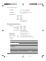
Printer Models and Options
Model LA30N is an 80-column printer and model LA30W is a 136-column printer. Both
models have a dual interface made up of Bitronics parallel and DEC-423 serial. The power
supply of the printer is either for 100-120 VAC input or for 220-240 VAC input. You must
specify the print line and the power rating when purchasing the printer. Other options
include a color print feature which you can add by yourself after purchasing the printer. The
configuration is:
LA30N/LA30W
Basic specifications
Print line at 10 cpi*: 80 columns for LA30N
136 columns for LA30W
Interfaces: Bitronics parallel and DEC-423 serial
Alternative specification
Power supply: 100–120 VAC or 220–240 VAC
User add-on options
Color Kit
* cpi: characters per inch
vii
#00_3 Preface
7
23/05/96, 13:55
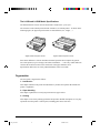
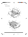
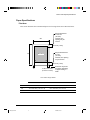
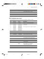
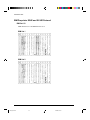
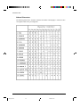
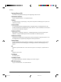
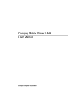
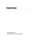
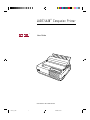
The LA30N and LA30W Model Specifications
The main difference between the LA30N and the LA30W is the “print span”.
The LA30N is an 80-column printer and the LA30W a 136-column printer. As shown in the
following figure, the physical specifications are thus different (size, weight, ...).
Digital LA30N Companion Printer
Digital LA30W Companion Printer
Some minor differences concern mechanical internal parts that do not impact the general
uses of the printer (top cover hinges, bail rollers mechanism, ...). The only visible difference
concerns the accurate location of the notch scale of the paper thickness lever.
Specification differences are clearly identified further in this User Guide.
Organization
The user guide is organized as follows:
1 - Introduction
This chapter introduces the printer and identifies key features and options that enhance the
printer’s capabilities.
2 - Paper Handling
This chapter explains how to load your printer and use paper with it.
3 - Printing
This chapter covers basic printing operations and provides detailed descriptions of everyday
operations from the printer’s control panel, including print feature selection.
viii
#00_3 Preface
8
23/05/96, 13:55
4 - Using Set-Up Mode
This chapter describes how to change the printer’s optional settings, such as print features,
hardware options, and top-of-form. Most settings only affect print features such as the type
style and page format. Note that certain settings directly affect hardware and software
compatibility. Refer to this chapter as indicated in the part Setting Up Your Printer or as
required.
5 - Maintenance
This chapter explains basic maintenance procedures for this printer.
6 - Trouble-Shooting
This chapter describes problem-solving techniques. Before you contact your dealer for help,
check the list of problems and solutions provided in this chapter.
At the end of this guide, you will find several appendices, a glossary, and an index.
Appendix A gives order numbers for printer supplies and options, explaining how to install
them. Other appendices provide additional technical information about the printer.
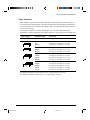
Notes, Cautions and Warnings
The text contains three different types of annotation which should always be read.
Note:
This NOTE annotation provides you with additional information, or indicates
where you can find it.
Caution:
This CAUTION annotation should catch your attention, advising you of a
particular situation/problem which may occur/be avoided as a result of a certain
sequence of operations. It may also contain a reminder to execute a particular
operation.
Warning: This WARNING annotation indicates a specific procedure which must be strictly
observed. Failure to comply with the instructions given may result in injury to the
operator and/or damage to the printer.
ix
#00_3 Preface
9
23/05/96, 13:55
#00_3 Preface
10
23/05/96, 13:55
Introduction
1
Introduction
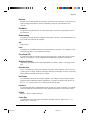
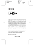
Congratulations on purchasing a Digital LA30 Companion Printer. This printer is a
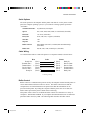
compact, versatile printer that offers maximum compatibility with today’s software packages
and personal computers. The 24-wire print head provides crisp, clear printing for business,
office, and home environments. This printer is also easy to install and use.
Digital LA30 Companion Printer
Features
Key printer features and options are listed in the next two sections.
•
Software compatibility. This printer, which operates with the DEC PPL2 protocol, the
IBM Proprinter X24E (LA30N) or IBM Proprinter XL24E (LA30W) protocol and the
Epson ESC/P2 protocol (for Epson LQ870 or LQ1170 printers or equivalent).
•
Various character sets. For the DEC PPL2 protocol, 31 character sets (twenty-five 94character sets and six 96-character sets) are available. For IBM Proprinter X24E and
XL24E protocol, set 1, set 2, and 30 default sets (code pages and specific character sets)
are available. For Epson ESC/P2 protocol, 15 national character sets and 30 default sets
(code pages and specific character sets) are available.
1-1
#01 Chapter 1
1
23/05/96, 14:12
Introduction
•
Multiple fonts. The printer has eighteen resident fonts: Ten bit-map fonts — Draft,
High-speed (HS) Draft, High-impact (Hi) Draft, Courier 10, Pica 10, Prestige Elite 12,
Compressed 17, Boldface PS, OCR A, and OCR B; six outline fonts — Timeless and
Nimbus Sans, each in upright, italic, and bold; three outline fonts — Courier in upright,
italic, and bold (available for the Epson ESC/P2 protocol only); and nine Barcode fonts
— Code 3 of 9, Industrial 2 of 5, Interleaved 2 of 5, Matrix 2 of 5, EAN 8, EAN 13,
UPC-A, Codabar, and Postnet.
•
High-speed printing. At 10 cpi, print speed ranges from 100 cps for letter quality to
333 cps for high-speed draft quality.
•
64K bytes of input buffer. 64K bytes are available for storing input data and
downloading custom fonts. A minimum download buffer capacity is available separately.
•
Simple switching of paper types. The ability to “park” continuous forms makes it easy
to switch between continuous forms and single sheets.
•
Bottom feeding capability. The tractor unit is removable and can be converted to pushfeed or pull-feed. Installing the tractor unit on the platen allows the paper to be fed
through the slot at the bottom of the printer.
•
Automatic tear-off advancing. With factory settings of the Set-Up mode, continuous
forms’ perforations are automatically advanced up to the tear bar at the end of each job
so that forms can be torn off. The tear-off feed can be also activated by pressing the
Pause button.
•
Auto viewing. Paper (continuous forms or single sheets) is automatically advanced at
the end of each printing so that the last printed line can be read.
•
Maintenance-free. The printer only requires periodic cleaning and changing of the
ribbon cartridge.
•
Windows printer driver. Printer drivers for Windows 3.x and Windows 95 are
delivered with your printer. The printer driver is a control program to be installed on
your computer for controlling document printing on your printer (for example,
controlling the page size, the paper orientation, and so on). It receives print data from
your application software, converts the data into commands that the printer can execute,
and sends the commands to the printer.
Options
Printer add-on options are listed below. For details, see Appendix A “Supplies and
Options”.
•
Color kit. You can turn your monochrome printer into a color printer. Seven-color
printing using a color ribbon is possible if supported by your software.
1-2
#01 Chapter 1
2
23/05/96, 14:12
Paper Handling
2
Paper Handling
This chapter explains how your printer uses paper. Topics covered are:
•
Getting to know the printer’s major parts and the control panel
•
Selecting paper
•
Overview of paper operations
•
Adjusting for paper thickness
•
Using single sheets
•
Using continuous forms (push-tractor feed and pull-tractor feed)
•
Feeding and positioning paper
•
Switching paper types
Tips for paper handling are given at the end of this chapter. Check that section if you are
using multipart forms, envelopes, or labels.
Getting to Know the Printer’s Major Parts and the Control Panel
This section describes the major parts and controls of the printer and operations of the
control panel. Take a moment to become familiar with the printer.
2-1
#02 Chapter 2
1
23/05/96, 14:15
Paper Handling
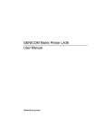
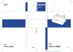
Parts of the Printer
!0
!1
q
o
w
e
i
r
t
u
y
!2
!8
!3
!7
!6
!4
!5
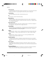
Front and Rear Views
2-2
#02 Chapter 2
2
23/05/96, 14:16
Paper Handling
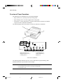
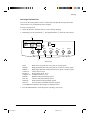
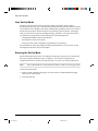
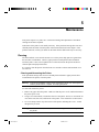
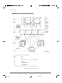
The figures on the previous page show front and rear views of the printer. The following
parts are indicated:
Front View
1. Front cover (to protect the print head)
2. Cut sheet stand (to hold printing and printed pages)
3. Paper thickness lever (to adjust the print head gap)
4. Platen knob (to manually advance the paper)
5. Platen (to support the paper)
6. Interface connector (to connect the printer to the host system)
7. Control panel (to load and feed paper, select print features, or change the
printer’s optional settings)
8. Power switch (to switch the printer on/off)
9. Paper select lever (to switch the paper source)
10. Print head (to apply ink to the page)
11. Print guide (to indicate the print line)
Rear View
12. Acoustic cover (to reduce sound noise)
13. Paper guide (to insert single sheets and envelopes)
14. Rating label (to indicate the printer power specifications)
15. Power connector (to connect the printer to the power supply)
16. Forms tractors (to hold and feed continuous forms)
17. Back cover (to protect forms tractors)
18. Top cover (to protect the platen and serve as the tear bar)
2-3
#02 Chapter 2
3
23/05/96, 14:16
Paper Handling
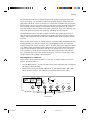
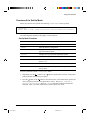
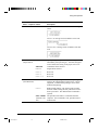
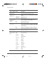
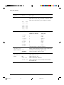
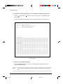
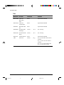
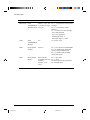
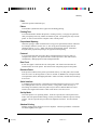
Operations of the Control Panel
This section summarizes status indications and operations of the control panel in Normal
mode. For details on Set-Up mode, see Chapter 4 “Using Set-Up Mode”.
Normal mode operation includes everyday operations, such as paper handling, font
selection, macro selection, and protocol selection. The first table lists basic states
represented by the Ready and Fault indicators. The second table lists Normal mode
operations and required user response. Operations are listed by functions.
Basic States of the Printer
Indicator
Status
Printer Status
Ready
On
The printer is ready for printing
or
The printer is receiving or printing data.
Blinking
The printer is not ready and holds printing data.
Off
The printer is not ready and it does not hold printing data.
On
The printer is out of paper.
Fault
Blinking slowly The printer has software errors (paper jam, interface
error, carriage error, paper unloading error, etc.).
Blinking fast
The printer detected diagnostic errors at power-up.
2-4
#02 Chapter 2
4
23/05/96, 14:16
Paper Handling
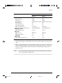
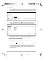
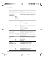
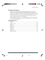
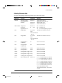
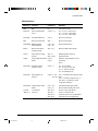
Control Panel Operations
—
N/A
: This operation has no connection with this condition.
: The condition does not apply because this operation is executed before powering on.
Required Conditions *1
Operation
Required Action
Ready
Printing *2
Fault
Load continuous forms paper
—
Not printing
On
Press FF/Load.
Load single sheet paper
—
Not printing
On
Press FF/Load if single sheet
load is switched from AUTO
to MANUAL in Set-Up mode.
Feed paper a page
—
Not printing
Off
Press FF/Load.
Feed paper a line
—
Not printing
Off
Press LF.
Advance perforation to tear bar
—
Not printing
Off
Press Pause if the TEAR
option is switched from AUTO
to MANUAL in Set-Up mode,
or press FF/Load.
Advance paper for viewing
—
Not printing
Off
Press Pause if the TEAR
option is switched from AUTO
to MANUAL in Set-Up mode.
Return paper to previous position —
Not printing
Off
Press Pause if the TEAR
option is switched from AUTO
to MANUAL in Set-Up mode,
or press FF/Load.
Eject single-sheet paper
—
Not printing
Off
Press FF/Load or Park or turn
the printer off and on again.
Unload continuous-forms
paper *3
—
Not printing
Off
Press Park.
Pause printing
On
Printing
Off
Press Pause.
Resume printing
Blinking Not printing
Off
Press Pause.
Resume printing after a fault
Off
Not printing
On
Clear error and press Pause.
Resume printing after paper-out
Off
Not printing
On
Load paper.
Place printer in Ready state
Off
Not printing
Off
Press Pause.
Place printer in pause state
On
—
Off
Press Pause.
Enter Normal mode
N/A
N/A
N/A
Turn power on without
pressing any buttons
Printing test
N/A
N/A
N/A
Turn power on while pressing
FF/Load.
2-5
#02 Chapter 2
5
23/05/96, 14:16
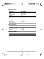
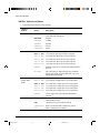
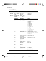
Paper Handling
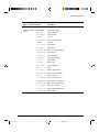
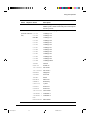
Required Conditions *1
Operation
Ready Printing
*2
Required Action
Fault
Select a resident font
—
Not printing
Off
Press Font.
Enter Macro selection mode
—
Not printing
Off
Press Macro. (M1 and M2
will turn blinking
alternately for 3 seconds.)
Select Macro 1
—
*4
Off
Press M1 within 3 seconds
after pressing Macro.
Select Macro 2
—
*4
Off
Press M2 within 3 seconds
after pressing Macro.
Switch the protocol
—
Not printing *4 Off
Press Protocol.
Enter Top-of-Form Adjustment mode
—
Not printing
Off
Press Set-Up/Quit and Top.
Move paper by 1/60 inch
Off
—
Off
Press
Use the adjustment temporarily
Off
—
Off
Press Set-Up/Quit.
Use the adjustment permanently
Off
—
Off
Press Exit/Save.
Clear the adjustment
Off
—
Off
Press Top.
N/A
N/A
N/A
Turn power on while
pressing Set-Up/Quit.
Move cursor to select
a Set-Up Function or Value
Off
Not printing
Off
Press
or
Move cursor to select
a Set-Up Option
Off
Not printing
Off
Press
or
button.
Select a Set-Up Function
or Value
Off
Not printing
Off
Press
or
button.
Select a Set-Up Value and
move cursor to SAVE&EXIT
Off
Not printing
Off
Press Exit/Save.
Quit Set-Up mode without
saving values
Off
Not printing
Off
Press Set-Up/Quit.
Clear software-detected errors
—
—
Blinking Press Pause.
Initialize the printer
—
—
—
Enter Set-Up mode
or
button.
button.
Turn power off and on again.
*1 In Normal mode operation, all buttons except Pause are inactive in the Busy state in which the printer is receiving
or printing data.
*2 Not printing includes the following situations: the printer is ready and awaiting data, or the Pause button is
pressed and the printer is awaiting data, or the Pause button is pressed during printing.
*3 This operation is available in the rear-feeding push-tractor mode.
*4 Switching is not done if the printer is holding printing data.
2-6
#02 Chapter 2
6
23/05/96, 14:16
Paper Handling
Printer Acoustical Feed-Backs
Except for paper handling and when the factory setting for beep is not changed, the printer
beeps in the following ways when you press a control panel button, as follows.
•
A short beep indicates that the printer accepts your pressing or specification.
•
A longer beep indicates that your specification is invalid.
•
In a certain mode, a middle long beep indicates that the specified mode becomes active
and a short beep indicates the end of the mode.
•
When the Fault indicator lights, the printer also makes a longer beep.
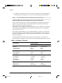
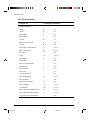
Selecting Paper
The printer can handle either single sheets or continuous forms. Single sheets, also called
cut sheets, include envelopes and noncontinuous, multipart forms. Continuous forms
include labels and multipart forms fed into the printer using the forms tractors.
For best results, use paper that meets the specifications listed in the following table. (See
Appendix B “Printer and Paper Specifications” for detailed specifications.) If you are
unsure of the suitability of a particular type of paper, try testing the paper or consult your
dealer.
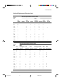
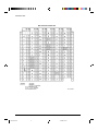
Paper Specifications
Paper Size
LA30N
LA30W
Continuous
Width
102 to 267 mm (4 to 10.5 in)
102 to 420 mm (4 to 16.5 in)
forms
Length
102 mm (4 in) or greater
102 mm (4 in) or greater
Cut sheets
Width
102 to 267 mm (4 to 10.5 in)
102 to 420 mm (4 to 16.5 in)
Length
76 to 364 mm (3 to 14.3 in)
76 to 420 mm (3 to 16.5 in)
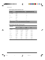
Paper Thickness and Number of Copies
Description
Thickness
0.35 mm (0.014 in) maximum total thickness.
Copies
1 to 5 copies, including the original.
For carbon-interleaved paper, the carbon counts as a copy.
2-7
#02 Chapter 2
7
23/05/96, 14:16
Paper Handling
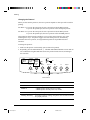
Overview of Paper Operations
The following levers and buttons are used in paper handling:
•
Paper select lever q at the top left corner of the printer
•
Paper thickness lever w at the top right corner of the printer
•
All buttons y on the control panel e (Primary and alternative functions are labelled
respectively above and under each button.)
The following figure shows the location of each lever, indicators, and buttons:
q
w
e
r
Draft
HSDraft
HiDraft
t
Courier 10
Prestige 12
Bold PS
Time PS
Comp. 17
Nimb. PS
Soft Ctrl.
Font
Ready
Pause
M1
Fault
DEC
PPX24
M2
Macro
Protocol
EP2
Park
M1
Set-Up/Quit
LF
FF/Load
M2
Top
Exit/Save
y
Paper select lever q
Paper thickness lever w
Control panel e
Font indicators r
Macro indicators t
Buttons y
Printer Levers and Buttons
The following table summarizes the use of levers and buttons in paper handling. More
detailed information is provided later in this chapter.
Caution:
To load or feed paper, the printer must be:
• In the Ready state but not receiving or printing data
• In the Pause state
2-8
#02 Chapter 2
8
23/05/96, 14:16
Paper Handling
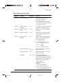
Levers and Buttons Used for Paper Handling
Lever/Button
Purpose
Action
FF/Load
Form feed
Press FF/Load to execute a form feed.
Continuous forms are fed forward by one
page. Single sheets are ejected.
Press FF/Load to feed paper to the top of
form position.
Load paper
LF
Line feed
Press LF to feed paper forward by one line.
Park
Unload forms
Press Park to retract continuous forms to
the “park position.”
Set-Up/Quit + Top
Enter Top-of-Form
(TOF) Adjustment
mode
Press Set-Up/Quit and Top at the same time
to enter TOF Adjustment mode where the
paper loading position can be adjusted.
button to feed paper forward
Increase TOF value by Press the
by 1/60 inch in TOF Adjustment mode.
1/60 inch
Decrease TOF value by Press the button to feed paper backward
by 1/60 inch in TOF Adjustment mode.
1/60 inch
Save TOF value
Press Exit/Save to permanently store the
TOF position adjusted by the
button and
the button in TOF Adjustment mode.
Pause
Advance forms to the
tear bar when forms
are at Top-of-Form
(TOF) position
Press Pause to advance the forms
perforation to the tear bar. Tear off the
forms, then press Pause again to return the
forms to the previous position.
Paper select lever *
Select paper path
Move the paper select lever forward for
single sheets.
Move the paper select lever backward for
continuous forms.
Exit/Save
Paper thickness lever Adjust for paper
Select the number corresponding to the
number
of copies (including the original).
thickness or number of
Vary
the
setting upward or downward
copies
(including A to D) to optimize printing.
Select D when replacing ribbon or clearing
a paper jam.
*
The following graphics are engraved on the casing.
Continuous forms
Single sheets
2-9
#02 Chapter 2
9
23/05/96, 14:16
Paper Handling
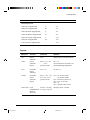
Adjusting for Paper Thickness
The printer can handle paper with different thicknesses, including multipart forms with up to
five parts (original plus four copies). For details on paper thickness specifications, see
Appendix B “Printer and Paper Specifications.”
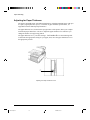
The paper thickness lever, located at the top right corner of the printer, allows you to adjust
for different paper thicknesses. Be sure to adjust the paper thickness lever whenever you
change the number of copies being printed.
The paper thickness lever q has nine settings: 1 to 5 and A to D. Use the following table
to determine the appropriate setting for your paper; then, move the paper thickness lever to
the appropriate position.
q
Adjusting the Paper Thickness Lever
2-10
#02 Chapter 2
10
23/05/96, 14:16
Paper Handling
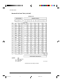
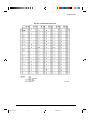
Paper Thickness Lever Positions
Number of Copies
(Including the Original) *1
Position *2
1 copy
1
2 copies
2
3 copies
3
4 copies
4
5 copies
5
Ribbon replacement
D
*1 For carbon-interleaved paper, the carbon counts as one copy.
*2 Vary the position upward or downward (including A to D) to optimize printing. Select D when replacing a
ribbon or clearing a paper jam. For labels and envelopes, use the trial-and-error approach to determine a
satisfactory position.
Caution:
If printing is messy, the ribbon misfeeds, or the paper jams, move the lever one
position higher.
Using Single Sheets
This section describes how to load paper in the cut sheet stand. The cut sheet stand allows
paper to be loaded manually, one sheet at a time.
Loading a Single Sheet of Paper
To load a sheet of paper into the cut sheet stand:
1. Make sure that the printer is turned on. Check that rear-fed continuous forms are
retracted to the park position. (For details, see the section “Unloading Continuous
Forms” later in this chapter.)
2. If necessary, reset the paper thickness lever. (See the section “Adjusting for Paper
Thickness” earlier in this chapter.)
3. Move the paper select lever forward. (This lever is at the top left part of the printer.)
4. Raise the cut sheet stand. Position the left paper guide in accordance with the Note
below. Note that the movable range of the paper guide is limited.
2-11
#02 Chapter 2
11
23/05/96, 14:16
Paper Handling
Note:
Below the left paper guide q, the cut sheet stand has a scale graduated in units
of 0.1 inch. When the left paper guide is positioned all the way to the right, the
left margin is 5 mm (0.2 inch). To help align paper, also use the inch-based ruler
on the top cover w of the printer. The gradations on the ruler are for 10
columns per inch.
w
q
Setting Paper Select Lever and Left Paper Guide
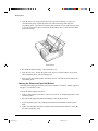
5. Adjust the right paper guide e to the width of paper. Insert the paper into the cut sheet
stand. Make sure that the bottom edge of the paper engages snugly with the platen. The
paper will automatically advance to the top-of-form position if the Single Sheet Load
option of the Set-Up mode is set to Automatic.
Note:
The factory setting for the Single Sheet Load option is automatic loading, two
seconds after paper detection. If you set this option to manual, you will have to
press FF/Load to feed the paper.
2-12
#02 Chapter 2
12
23/05/96, 14:16
Paper Handling
e
Loading a Sheet of Paper
6. If you want to slightly adjust the Top-of-Form position, the first line on which printing
can start, adjust the Top-of-Form position of the paper using control panel buttons. Press
the Set-Up/Quit and the Top buttons at the same time. The M1 and M2 indicators flash
alternately with the DEC and PPX24 indicators, indicating Top-of-Form Adjustment
mode. Press the
button or the button. The paper will move forward or backward
in 1/60-inch increments. Press the Set-Up/Quit button after adjusting the position. Note
that this adjustment is temporarily saved. It will not be active at next power-up of the
printer. For permanent adjustment, see the section “Feeding and Positioning Paper” later
in this chapter.
7. Place the printer in the Ready state. Print a sample page and check the page margins.
Make the following adjustments, as necessary:
•
Horizontal alignment. Readjust the paper guides if required.
•
Top-of-form setting. Use the printer Set-Up mode (see Chapter 4 “Using Set-Up
Mode”) or the TOF Adjustment mode (see the section “Feeding and Positioning
Paper” later in this chapter).
•
Margin settings. Use your software or the printer Set-Up mode (see Chapter 4
“Using Set-Up Mode”).
Ejecting Single Sheets
If you print using software, each sheet is ejected automatically upon the completion of the
page printing. To manually eject sheets of paper:
•
Press the FF/Load button to execute a forward form feed.
•
Turn the platen knob.
2-13
#02 Chapter 2
13
23/05/96, 14:16
Paper Handling
Using Continuous Forms
Continuous forms paper, fanfolded at the horizontal perforations, is ideal for printing rough
drafts and long files. The paper is fed into the printer using the forms tractor unit. The
forms tractor unit, which is removable, can be used in two different ways. If the forms
tractor unit is mounted at the rear of the printer, it pushes paper from the rear to the platen.
This is called push-tractor feeding. If the forms tractor unit is mounted at the top of the
printer, it pulls paper from the bottom or rear of the printer to the platen. This is called pulltractor feeding.
Caution:
When using continuous forms with the cut sheet stand in up position, always
spread the cut sheet stand paper guides to their extreme position before feeding
the paper. This will prevent the paper from jamming against the acoustic cover.
2-14
#02 Chapter 2
14
23/05/96, 14:16
Paper Handling
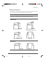
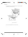
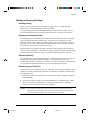
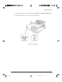
Positioning the Paper Stack
Place the stack of continuous forms paper directly below the rear of the printer q for push,
rear feed or below the bottom slot of the printer w for pull, bottom feed.
Caution:
When using paper-stapled multipart forms in push feed, raise the cut sheet stand e.
After the paper is installed in the printer, the paper path should look like this:
Good placement
e
q
Push-feed, from rear slot
Push-feed, from rear slot
with paper-stapled multipart forms
w
Pull-feed, from bottom slot
Bad placement
Placement of Continuous Forms
2-15
#02 Chapter 2
15
23/05/96, 14:16
Paper Handling
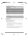
Loading Continuous Forms (Push Tractor and Rear Feed)
This section explains how to use continuous forms when the tractor unit is installed at the
rear of the printer. The tractor unit pushes continuous forms. This condition applies when
you first use the printer.
To load continuous forms paper:
1. Make sure that the printer is turned on. Remove any single-sheet paper from the printer.
2. If necessary, readjust the paper thickness lever for continuous forms. (See the section
“Adjusting for Paper Thickness” earlier in this chapter.)
3. Move the paper select lever q to the rear of the printer.
e
r
w
q
Preparing to Load Continuous Forms Paper
4. To access the forms tractors w, lock the cut sheet stand e and the back cover r
together and raise them in the up position.
2-16
#02 Chapter 2
16
23/05/96, 14:16
Paper Handling
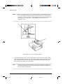
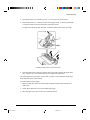
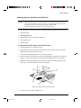
5. For both forms tractors w, release the tractor locking levers t by pulling them up.
Open the tractor paper holders y.
y
u
t
12 mm
Positioning the Tractor Using the Tractor Guide
6. Position the right forms tractor (as seen from the rear of the printer) in accordance with
the Note below. Push the right locking lever down to secure the tractor. Center the
middle forms support.
Note:
The tractor guide u can be found below the right forms tractor, as seen from the
back. This tractor guide is a short inch-based ruler graduated in 10 columns per
inch. Use this ruler to help position the tractor. When the paper edge is
positioned to the leftmost line, the left margin is 12 mm (0.5 inch) including the
perforation area.
7. Once the right forms tractor is positioned, lock it by pushing down its locking lever.
2-17
#02 Chapter 2
17
23/05/96, 14:17
Paper Handling
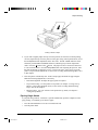
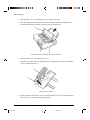
8. Fit the paper feed holes onto the left and right tractor pins. Adjust the left forms tractor
(as seen from the rear of the printer) to accommodate the width of the form. Close the
paper holders y.
y
Adjusting Paper Tension
9. Pull the left tractor (as seen from the rear) to extend the paper flat. Do not stretch the
paper taut. Push the left locking lever down to secure the tractor in place. Unlock the
back cover from the cut sheet stand to close it.
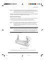
10. When using paper-stapled multipart forms, leave the cut sheet stand e raised in the up
position. For other continuous forms paper, lower the cut sheet stand to the down
position.
e
Lowering the Cut Sheet Stand
11. Press the FF/Load button to advance the paper to the top-of-form position from which
printing can start. The printer is automatically placed in the Ready state.
2-18
#02 Chapter 2
18
23/05/96, 14:17
Paper Handling
12. Print a sample page and check the page margins. Make the following adjustments, as
necessary:
– Horizontal alignment. Move the forms tractors as required.
– Top-of-form setting. Use the printer Set-Up mode (see Chapter 4 “Using Set-Up
Mode”) or the Top-of-Form Adjustment mode (see the section “Feeding and
Positioning Paper” later in this chapter).
– Margin settings. Use your software or the printer Set-Up mode (see Chapter 4
“Using Set-Up Mode”).
Loading Continuous Forms (Pull Tractor and Bottom Feed)
Caution:
When manipulating the tractor unit, always be careful not to pull on plastic
parts (below the forms tractors) in order to avoid printing problems (such as
printing on the platen at the end of the paper in push-feed).
Better manipulate the metallic parts of the tractor unit.
This subsection explains how to use continuous forms when the forms tractor unit is
installed at the top of the printer. The forms tractor unit pulls continuous forms. This is
called pull-tractor feed. To use pull-tractor feed, you must remove the forms tractor unit
from the rear of the printer and install it on the top of the printer.
For pull-tractor feed, this printer is equipped with a paper path slot at the bottom of the
printer to allow for continuous forms feed from under the printer. You must use a desk or
rack that has an appropriate paper path slot. For the appropriate paper path, see the section
“Positioning the Paper Stack” earlier in this section.
Warning: Turn the printer off before reinstalling the forms tractor unit.
To reinstall the forms tractor unit for pull-tractor feed:
1. Set the cut sheet stand and the back cover together to the up position to access the forms
tractor unit.
2-19
#02 Chapter 2
19
23/05/96, 14:17
Paper Handling
2. Pull up both ends of the tractor unit to detach the catches q of the tractor unit from the
support studs w. Then pull the tractor unit.
q
w
Removing the Tractor Unit
3. Set the cut sheet stand and the back cover to the down position.
2-20
#02 Chapter 2
20
23/05/96, 14:17
Paper Handling
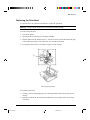
4. Open the acoustic cover and the top cover e to access the top of the printer.
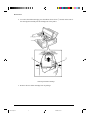
5. Position the catches q of the tractor unit on the support studs r near the platen shaft.
A. Push the forms tractor unit toward the front of the printer.
B. Snap down the tractor unit into place so that the catches click on the rear studs.
B
K
q
A
K
r
e
Installing the Tractor Unit for Pull-tractor Feed
6. Turn the platen knob to make sure that the tractor gear fully engages the platen shaft
gear. Lean the top cover and the acoustic cover against the tractor unit.
The following are the procedures to take when you want to feed continuous forms paper
from under the printer (bottom feed).
To load continuous forms paper:
1. Make sure that the bottom slot of the printer is adjusted with the slot of the desk or
printer rack.
2. Set the paper thickness lever to position D (widest gap).
3. Move the paper select lever to the rear (continuous forms).
2-21
#02 Chapter 2
21
23/05/96, 14:17
Paper Handling
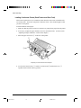
4. Open the front cover q, with taking care of not totally removing it.
5. Place the continuous forms paper below the table and pass the paper through the slot of
the table then through the bottom slot of the printer up to the platen.
q
Passing Continuous Forms Paper From Under the Printer
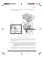
6. Close the front cover q and open the top cover.
7. Open the two holders of the left and right tractors. (Each tractor has a larger main holder
w and a smaller subholder e.)
w
e
Opening the Two Holders
8. Set the continuous forms on the tractors and position the tractors to stretch the forms taut
in the same way as described for push-tractor feed.
2-22
#02 Chapter 2
22
23/05/96, 14:18
Paper Handling
9. Turn the platen knob r to adjust the print start position and turn the printer on. The
horizontal embossed rib under the red cursor on the print head carriage corresponds to
the base line of the characters to be printed.
r
Setting Continuous Forms Paper on the Tractors
10. Lean the top cover against the tractor unit.
11. Adjust the paper thickness lever to the appropriate position.
12. Press the Pause button to place the printer in the Ready state. Print a sample page and
check the first line and the page margins. Make the following adjustments, as necessary:
– Horizontal alignment. Move the forms tractors as required.
– Margin settings. Use your software or the printer Set-Up mode (see Chapter 4
“Using Set-Up Mode”).
Caution:
In the pull-feed mode, reverse feeding is allowed up to 1/3 inch and the print
accuracy is lower than the accuracy available with the push-feed mode. Use the
pull-feed mode when printing labels and so on that are affected by curling.
2-23
#02 Chapter 2
23
23/05/96, 14:18
Paper Handling
Unloading Continuous Forms (Push-Feed Mode)
To unload continuous forms:
1. Make sure that the paper select lever is set to the rear position.
2. Press the Park button. The continuous forms paper is retracted to the park position. If
the paper cannot be retracted in one operation, continue to press the Park button until the
paper is parked.
Note:
The printer can retract continuous forms paper a maximum of 50.8 cm (20
inches) per operation.
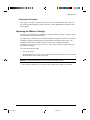
3. To remove the paper, raise the tractor paper holders and lift out the paper.
Note:
To unload continuous forms fed by the pull-tractor, set the paper thickness lever
to D, then remove the paper manually.
Recovering from an Unexpected Unloading Operation
If you have accidentally pressed the Park button, you can cancel this operation in two ways,
only if this unexpected operation was unsuccessful (paper not actually parked and Fault
indicator blinking).
•
Press the Pause button.
The printer switches to the Ready state and the paper moves according to the setting of
the TEAR Set-Up option.
•
Press the FF/Load button.
The paper moves back to the place it was positioned before you pressed the Park button.
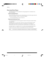
Tearing Off Continuous Forms
Caution:
Continuous forms paper that is fed by the pull-tractor cannot be torn off in the
following way.
Automatic-Tear-Off Advancing
Your printer has a special “tear bar” that allows you to tear off printed pages without wasting
paper. The tear bar is located on the top cover.
Your printer is factory-set for automatic tear-off. When a printing job ends (including a
form feed command), the bottom perforation of the last printed page is automatically
positioned in front of the tear bar. You can change the positioning delay from one to five
seconds, using the Set-Up mode. The printer is placed in the Pause state (Ready indicator
off).
2-24
#02 Chapter 2
24
23/05/96, 14:18
Paper Handling
Note:
If the printing job does not include a form feed command, the paper is only
automatically fed so that you can see the last printed line. Press on the FF/Load
button to position the next paper perforation in front of the tear bar.
The paper is automatically retracted when the printer receives the next data. For tearing off
the paper, see the next subsection “Manual Tear-Off Advancing”.
Manual Tear-Off Advancing
If you have set the TEAR option of the INSTALL function to MANUAL, tear off the paper in
the following way when a printing job ends (including a form feed command).
1. Press the Pause button to position the paper perforation in front of the tear bar.
Note:
If the printing job does not include a form feed command, after pressing the
Pause button the paper is only automatically fed so that you can see the last
printed line. Press on the FF/Load button to position the next paper perforation
in front of the tear bar.
Caution:
If the paper perforation is not positioned in front of the tear bar, the length of
your paper may not be specified correctly in your software or the Set-Up mode.
Check that the paper length is specified correctly. For information on specifying
page length using the Set-Up mode, see Chapter 4 “Using Set-Up Mode”.
2. Tear the paper off at the perforation.
Tearing Off Continuous Forms
3. Press the Pause button again to retract the forms back to the top-of-form position.
2-25
#02 Chapter 2
25
23/05/96, 14:18
Paper Handling
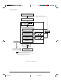
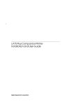
Feeding and Positioning Paper
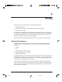
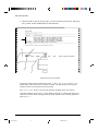
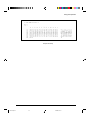
Print Area Definition
•
TOF (Top-of-Form):
This value defines the distance between the edge of the paper and the place where you
allow the printing to begin (position of line number 1). You can adjust this distance
according to the condition of your paper (for example, pre-printed forms). When you
load the paper, the printer feeds the paper to this position, waiting for printing
commands.
•
L (Form Length):
Set the corresponding Set-Up option (FORM LENGH) according to the actual physical
page length (distance between two perforations for continuous forms). This will allow
the printer to know exactly where the print head is and to position it at the same position
when a form feed occurs.
•
Top line q:
This is the line where the printing actually starts. To define a top margin, select the
number of this line within Set-Up mode (TOP MRGN option). Example: In the
following picture, TOP MRGN option is set to 3.
•
Bottom line w:
This is the line where the printing actually stops. To define a bottom margin, select the
number of this line within Set-Up mode (BOTTOM MRG option). Example: In the
following picture, BOTTOM MRG option is set to 50.
•
Left column e:
This is the column where the printing actually starts. To define a left margin, select the
number of this column within Set-Up mode (LEFT MARGN option). Example: In the
following picture, LEFT MARGN option is set to 4.
•
Print area r:
Print area defined by the corresponding Set-Up options: Form Length, Top-of-Form,
Top Margin, and Bottom Margin.
•
Paper perforation t:
The perforation defines the physical page length.
2-26
#02 Chapter 2
26
23/05/96, 14:18
...
1
2
3
4
5
6
Paper Handling
e
TOF
ABCDEFGHIJ ···
ABCDEFGHIJ ···
q
...
1
2
3
4
5
6
7
8
r
...
L
48
49
50
51
52
ABCDEFGHIJ ···
w
t
TOF
...
1
2
3
4
5
6
Print Area Definition
2-27
#02 Chapter 2
27
23/05/96, 14:18
Paper Handling
Line Feed/Form Feed
Use the line feed/form feed function to move paper forward. This function is valid
whenever the printer is not receiving or printing data and has no fault. Pressing the LF
button advances the paper one line. Pressing the FF/Load button feeds one sheet of paper.
Except using the Park button for unloading paper or using the Top-of-Form Adjustment
mode for fine-adjusting the Top-of-Form position, you are not allowed to execute “reverse”
feed from the control panel. To feed paper backward, manually rotate the platen knob.
Remember that the Top-of-Form will slip from the original setting.
Top-of-Form Adjustment
Note:
To know the Top-of-Form definition, see the previous section “Print Area
Definition”.
The Top-of-Form adjustment is available for single sheets or continuous forms fed by the
push-tractor. The adjustment is reflected to the Top-of-Form setting of Macro 1 or Macro 2
currently selected from the control panel.
Note:
This adjustment is not available for continuous forms fed by the pull-tractor.
You can adjust the Top-of-Form value within the range from 0 to 99/60 inches.
Note:
The horizontal embossed rib under the red cursor on the print head carriage
corresponds to the base line of the characters to be printed.
1. Position the paper at the current Top-of-Form position:
– For continuous forms, park the paper, then press the FF/Load button.
– For a single sheet, simply insert the sheet in the cut sheet stand.
Paper is automatically fed to the Top-of-Form position, if the Set-Up option
S-SHEET LD (Single Sheet Load) is set to AUTO. Otherwise, press the FF/Load
button.
2. Enter the Top-of-Form mode by pressing the Set-Up/Quit and Top buttons at the same
time. The printer beeps and the M1 and M2 indicators flash alternately with the DEC and
PPX24 indicators, indicating the Top-of-Form mode.
2-28
#02 Chapter 2
28
23/05/96, 14:18
Paper Handling
3. Adjust the Top-of-Form value:
– To increase the Top-of-Form value of a 1/60 inch, press the
The paper moves forward.
button.
– To decrease the Top-of-Form value of a 1/60 inch, press the
The paper moves backward.
button.
– To reset the Top-of-Form value to 0, press the Top button.
The paper moves to the edge of the page (position 0).
Note:
If you reach the limit of the permitted range, the printer beeps and the paper
stops moving.
4. Save the Top-of-Form value:
– To permanently save the value, press the Exit/Save button.
The printer returns to Normal mode.
– To temporarily save the value, press the Set-Up/Quit button.
The printer returns to Normal mode. (The new value is lost at next power-off.)
Note:
The use of the
and buttons for micro-feeding is available for some cases of
software errors (Fault indicator blinking).
Switching Paper Types
If you have more than one type of job, it is often necessary to switch between continuous
forms and single sheets. This section explains how to switch between paper types. It is not
necessary to remove the continuous forms paper from the printer.
Caution:
This function is not available for continuous forms paper that is fed by the pulltractor.
2-29
#02 Chapter 2
29
23/05/96, 14:18
Paper Handling
Switching from Continuous Forms to Single Sheets (Push-Feed Mode)
To switch from continuous forms to single sheets:
1. Tear off your printed pages.
2. Retract the forms paper to the park position by pressing the Park button. The Fault
indicator turns on.
Caution:
Retracting many pages by using the Park button without tearing off will cause
paper jams. To avoid damage to your printed pages, be sure to tear off the
printed pages before retracting the continuous forms paper.
3. Move the paper select lever forward to the single sheet position.
4. Raise the cut sheet stand to the up position. (For details, see the section “Using Single
Sheets” earlier in this chapter.) Put a sheet of paper on the cut sheet stand with its
bottom edge aligned with the platen. The paper automatically advance to the top-ofform position if the option S-SHEET LD (Single Sheet Load) is set to AUTO.
Otherwise, press the FF/Load button to advance the single sheet paper to the top-of-form
position .
You are now ready to print using single sheets.
Switching from Single Sheets to Continuous Forms (Push-Feed Mode)
To switch from single sheets to continuous forms:
1. If a sheet of paper is loaded, remove the paper by turning the platen knob or pressing the
FF/Load button.
2. Move the paper select lever to the rear to the continuous forms position.
3. Press the FF/Load button. The continuous forms paper advances from the park position
to the top-of-form position.
You are now ready to print using continuous forms paper.
2-30
#02 Chapter 2
30
23/05/96, 14:18
Paper Handling
Switching between Push-Feed and Pull-Feed
Caution:
When manipulating the tractor unit, always be careful not to pull on plastic
parts (below the forms tractors) in order to avoid printing problems (such as
printing on the platen at the end of the paper in push-feed).
Better manipulate the metallic parts of the tractor unit.
To allow the printer to properly detect the switching operation, follow the next procedure:
1. Unload the paper.
2. Turn the printer off.
3. Install the tractor unit for the other feed mode.
4. Turn the printer on.
5. Load the paper.
To Reinstall the Tractor Unit for Push-Tractor Feed:
1. Open the acoustic cover and the top cover.
2. Pull up both ends of the tractor unit to detach the catches of the tractor unit from the
support studs. Then pull the tractor unit.
3. Set the cut sheet stand and the back cover to the up position.
4. Keep the tractor unit horizontally (see the horizontal plane in the figure) so that the top
catches q of the tractor unit are in front of the inner support studs w of the printer.
5. Push the tractor unit toward the front of the printer until the top catches snap into the
inner studs. Then snap down the tractor unit into place.
q
w
Installing the Tractor Unit for Push-tractor Feed
6. Close the top cover and the acoustic cover.
2-31
#02 Chapter 2
31
23/05/96, 14:18
Paper Handling
Tips on Paper Handling
General Tips
•
Use high-quality paper. Do not use paper that is wrinkled or curled at the edges.
•
Do not use paper with staples or metal parts.
•
Do not use paper with unpredictable variations in thickness, such as paper with partial
multilayers, paper with embossed printing, and labels with the backing sheet exposed.
•
Store paper in a clean, dry environment.
Multipart Forms
•
Avoid using carbon-interleaved single sheets if possible. Printing tends to become
misaligned on the bottom sheet.
•
Set the paper thickness lever to best accommodate the multipart form thickness.
•
To ensure smoother feeding of paper-stapled, multipart forms, raise the cut sheet stand to
support the forms.
Envelopes
When printing envelopes, use the cut sheet stand. Note the following:
•
Set the paper thickness lever to best accommodate the envelope thickness.
•
When loading envelopes, make sure that the envelope flaps face forward. Otherwise, the
envelopes may jam in the printer.
Labels
•
Be careful to check operating conditions when using labels. Labels are sensitive to
temperature and humidity.
•
Only use labels mounted on continuous forms backing sheets. Do not print labels
mounted on single sheet backing. Labels mounted on single sheet backing tend to slip
and printing becomes crooked.
•
Do not leave labels loaded in the printer. If labels curl around the platen, jamming may
occur when printing is resumed.
•
Set the paper thickness lever to best accommodate the label thickness.
•
Test-print labels before running a job. If jams occur, set the paper thickness lever to a
wider position. If jamming problems continue, try a different type of label.
•
We recommend you to use the pull-tractor feed mode for printing labels. If using the
push-tractor feed mode:
– Use the NO TEAR value of the TEAR option in the Set-Up mode.
– Do not unload labels using the Park button. Jamming may occur during backward
feeding.
– Do not use the printer tear-off feature when printing labels. If the labels are retracted,
the backing may peel off and the labels may jam in the printer.
2-32
#02 Chapter 2
32
23/05/96, 14:18
Printing
3
Printing
This chapter describes the following everyday printing operations:
•
Selecting print features
•
Starting, stopping, or resuming printing and viewing last printed lines
•
Removing printed pages
The Font button, the Macro, M1, and M2 buttons, the Protocol button, and the Pause button
are used for these operations which are described in detail in this section. For a summary of
the operation of these buttons, see the section “Getting to Know the Printer’s Major Parts
and the Control Panel” in Chapter 2 “Paper Handling”.
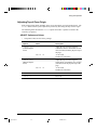
Instructions for loading and handling paper are also given in Chapter 2 “Paper Handling”.
Selecting Print Features
The print features you select determine how your printer interprets commands from the
computer and how your printed pages will look. For example, print features include the
following:
•
Protocol
•
Font
•
Pitch (characters per horizontal inch)
•
Line spacing (lines per vertical inch)
•
Page length and margins
To select print features, you can use either commercial software or the printer control panel.
The method you use depends on the capabilities of your software. If your software has most
of the features you require, you may rarely – if ever – have to use the control panel. In fact,
your software often overrides the printer settings.
If your software has limited values, you can use the printer control panel to select print
features. Sometimes, the control panel enables you to select features not available through
your software. For example, you can change the top-of-form position or select a character
set for printing your document.
3-1
#03 Chapter 3
1
23/05/96, 14:28
Printing
Using Commercial Software
Many commercial software packages offer a wide variety of print features, including some
features that are not supported by this printer. For example, software often provides a wider
range of font sizes than the printer can accommodate. Software also allows you to specify
multiple fonts on a single page and multicolor printing. To determine which features your
software supports and how to select them, refer to your software documentation.
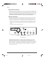
Using the Control Panel
This printer can directly select some print features from the control panel. These features,
listed on the control panel, are two predetermined sets (macros) of print features, nine
resident fonts, and three protocols. Use the Macro, Font, and Protocol buttons as follows:
•
Macro to select one of the two sets of print features, Macro 1 (M1) and Macro 2 (M2)
•
Font to select one of nine resident fonts (You can access three other fonts in Set-Up
mode)
•
Protocol to select one of the three protocols
Draft
HSDraft
HiDraft
Courier 10
Prestige 12
Bold PS
Time PS
Comp. 17
Nimb. PS
Soft Ctrl.
Font
Ready
Pause
M1
Fault
DEC
PPX24
M2
Macro
Protocol
EP2
M1
Set-up/Quit
Park
LF
FF/Load
M2
Top
Exit/Save
Printer Control Panel
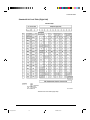
The Macro button specifies Macro 1 or Macro 2, either of which allows you to specify
different sets of values in advance. Some of the print features include protocol, font,
character pitch, and line spacing. The following table lists the default values of options in
Macro 1 and Macro 2. This chapter does not explain how to assign values to options in the
macro. If you haven’t already assigned values to Macro 1 and Macro 2, see Chapter 4
“Using Set-Up Mode” now.
3-2
#03 Chapter 3
2
23/05/96, 14:28
Printing
The Font button specifies one of the nine resident fonts defined by font names and pitches
on the control panel. The selectable resident fonts are Draft, High-speed (HS) Draft, and
High-impact (Hi) Draft, Courier 10, Prestige 12, Compressed 17, Boldface PS, Timeless PS,
Nimbus Sans PS. Even if you select a font (excepting Soft Control), the printer will monitor
font commands from the computer, but continue to use the font specified by the control
panel until another selection is made or the printer is turned off. If you select Soft Crtl, (Soft
Control) the printer will use the font specified by commands from the computer.
The Protocol button allows you either to choose one of the three resident protocols or to
allow the printer to automatically switch to one of the three protocols, according to Set-Up
settings. The resident protocols are DEC PPL2, IBM Proprinter X24E, and Epson ESC/P2
protocols.
When you first turn the printer on, the M1 indicator is lit with the DEC and PPX24 indicators
flashing alternately, the Soft Ctrl. indicator is lit, and the Ready indicator is lit (the Fault
indicator will be lit if no paper is loaded). That is, all of the print features assigned to Macro
1 are enabled; fonts used depend on font commands from the computer but the Draft font is
used if no font command is received (because the FONT option is set to DRAFT in Set-Up
mode for Macro 1); and the printer assigns the DEC PPL2 protocol to the serial interface
port, and the Epson protocol to the parallel interface port. However, you can easily switch
to other settings before printing as described below:
Selecting Macro 1 or Macro 2
When you first turn the printer on, Macro 1 is selected. To change to Macro 2 or back to
Macro 1, proceed as follows:
1. Press the Macro button q to place the printer in the macro changeable state. The M1 and
M2 indicators blink alternately.
2. Within three seconds, press the M1 or M2 button w. The lighted indicator (M1 or M2)
shows the macro selected. This selection is permanently retained in the printer.
Draft
HSDraft
HiDraft
Courier 10
Prestige 12
Bold PS
Time PS
Comp. 17
Nimb. PS
M1
Fault
DEC
PPX24
Ready
Pause
Soft Ctrl.
Font
M2
Macro
Protocol
EP2
Park
M1
Set-up/Quit
LF
FF/Load
M2
Top
Exit/Save
q
w
Control Panel
3-3
#03 Chapter 3
3
23/05/96, 14:28
Printing
3. To change to a resident font, see the next section. Otherwise, press the Pause button to
return the printer to the Ready state. You are ready to print using the selected macro.
Note:
The active Macro at power-off remains active at next power-up.
Switching Macros and Selecting Features on the Control Panel
When you switch from a macro to another, each modification you made using the control
panel for the Top-of-Form option or the Protocol option is lost, and the values of these
options stored in the new macro become active.
This behavior does not apply to the Font selection. If you have changed a font using the
control panel before changing the macro, this font will still remain active, overriding the
font set in the new macro.
For example, assume that Macro 1 is set to Draft and Macro 2 to Courier. You switch the
Font selection of Macro 1 from Draft to Prestige using the Font button. When you switch
the Macro selection from Macro 1 to Macro 2, Prestige will remain active, overriding the
Courier set in Macro 2.
The following tables list default values of options for print features. The former is for
options in Macro 1 and Macro 2 and the latter is for options independent of Macro selection.
Macro 1 and Macro 2 Settings
Print Feature
Factory Settings
Macro 1
Macro 2
Protocol
Protocol serial
Protocol parallel
Port dependent
DEC
EPSON
Port dependent
DEC
IBM
Font
Horizontal pitch
Vertical pitch
Draft
10 cpi
6 lpi
Draft
10 cpi
6 lpi
Form length
Left margin
Top of Form *1
Top margin
Bottom margin
11 inches (A)
1 column
0/60 inch
1 line
66 lines
11 inches (A)
1 column
0/60 inch
1 line
66 lines
Line mode
Paper source *2
Print direction
LF = LF, CR = CR
Tractor
Soft control
LF = LF, CR = CR
Tractor
Soft control
3-4
#03 Chapter 3
4
23/05/96, 14:28
Printing
Print Feature
DEC mode
DEC printer ID
Auto wrap
EOT disconnect
Initial report
Auto answerback
Answerback on ENQ
DEC G0 character set
DEC user preference character set
IBM&Epson mode
Default Character set
IBM mode
IBM set 1 or 2
IBM double height
IBM AGM
Epson mode
Epson national character set
Factory Settings
Macro 1
Macro 2
PPL2
Wrap
No disconnect on EOT
No
No
No
US ASCII
DEC Supplemental
PPL2
Wrap
No disconnect on EOT
No
No
No
US ASCII
DEC Supplemental
CP 437
CP 437
IBM set 1
No
No
IBM set 1
No
No
USA
USA
*1 When you change the Macro selection and that the new Top-of-Form value is different
from the former, paper is automatically fed to the next page, using the new Top-of-Form
value.
*2 When you change the Macro selection and that the paper source selection is different, the
printer automatically parks the continuous forms (in Push-Feed mode only) or ejects the
cut sheet. The Fault indicator blinks, indicating you should change the position of the
paper select lever.
Note:
You cannot attempt to change the Macro selection when the printer is printing,
even if you switch to the Pause state.
3-5
#03 Chapter 3
5
23/05/96, 14:28
Printing
Installation Settings
Print Feature
Factory Settings
Language
Tear
Single sheet loading
Error beep
English
Auto, 1 second
Auto, 2 second
One
Buffer
64K bytes
Interface type
Auto interface switch time
Baud rate
Bits and parity
Buffer control
Disconnected on fault
Automatic sense
2 seconds
9600 bps
8 bits and none
XON/XOFF
No
Adjustments Settings
Print Feature
Factory Settings
Fanfold adjust (continuous forms)
Manual adjust (single sheets)
Reserved 1
Reserved 2
0/60 inch
0/60 inch
0/60 inch
0/60 inch
Menu Access Settings
Print Feature
Factory Settings
Menu access
All functions allowed
3-6
#03 Chapter 3
6
23/05/96, 14:28
Printing
Selecting a Resident Font
You can use the control panel to select a resident font other than the font specified in the
selected macro or by commands from the computer.
To select a resident font:
1. Switch the printer to the Pause state if you are currently printing.
2. Repeatedly press the Font button q. The lighted indicator w shows the font selected.
w
Draft
HSDraft
HiDraft
Courier 10
Prestige 12
Bold PS
Time PS
Comp. 17
Nimb. PS
Soft Ctrl.
Font
Ready
Pause
M1
Fault
DEC
PPX24
M2
Macro
Protocol
EP2
M1
Set-up/Quit
Park
LF
FF/Load
M2
Top
Exit/Save
q
Control Panel
Draft:
HSDraft:
HiDraft *:
Courier 10:
Prestige 12:
Compress 17:
Bold PS:
Time PS:
Nimb. PS:
Soft Ctrl:
Draft font at any pitch (last active pitch or software pitch)
High-speed draft font at any pitch (last active pitch or software pitch)
High-impact draft font at any pitch (last active pitch or software pitch)
Courier font at 10 cpi
Prestige Elite font at 12 cpi
Compressed font at 17 cpi
Boldface font proportionally spaced
Timeless font proportionally spaced
Nimbus Sans font proportionally spaced
Font selected by commands from the computer
* The HiDraft font optimizes print quality for multipart forms.
3. Press the Pause button to return the printer to printing, if necessary.
3-7
#03 Chapter 3
7
23/05/96, 14:28
Printing
Changing the Protocol
When you first turn the printer on, the active protocol depends on what port will be used for
printing.
For Macro 1: If you use the serial port, the active protocol will be the DEC protocol.
If you use the parallel port, the active protocol will be the Epson protocol.
For Macro 2: If you use the serial port, the active protocol will be the DEC protocol.
If you use the parallel port, the active protocol will be the IBM protocol.
This printer has three protocols and allows you to set the protocol mode in one of the
following three ways: the printer engages one of the three protocols, automatically
determines the active protocol, or assigns different protocols for parallel and serial
interfaces.
To change the protocol:
1. Make sure the printer is in the Ready state (no data to be printed).
2. Repeatedly press the Protocol button q. The DEC and PPX24 indicators turn on and off.
The combination of lighted indicators shows the protocol mode selected, according to
the next table.
Draft
HSDraft
HiDraft
Courier 10
Prestige 12
Bold PS
Time PS
Comp. 17
Nimb. PS
M1
Fault
DEC
PPX24
Ready
Pause
Soft Ctrl.
Font
M2
Macro
Protocol
EP2
M1
Set-up/Quit
Park
LF
FF/Load
M2
Top
Exit/Save
q
Control Panel
Indicator Status
Active Protocol
DEC lit
DEC PPL2 protocol
PPX24 lit
– IBM Proprinter X24E protocol (LA30N)
– IBM Proprinter XL24E protocol (LA30W)
Both lit (EP2)
Epson ESC/P2 protocol
Flashing alternately
According to Set-Up settings, the printer waits for data to switch
to a proper protocol.
3-8
#03 Chapter 3
8
23/05/96, 14:28
Printing
Starting or Stopping Printing
Starting Printing
Before you start to print, make sure that paper is loaded. Also, verify that the paper
thickness lever is set to the appropriate position (1 to D).
To start printing, make sure that the Ready indicator is lit (the printer is ready). If not so,
press the Pause button to place the printer in the Ready state. Then start your software.
Stopping and Viewing Printing
To stop printing, press the Pause button to place the printer in the Pause state. The printer
stops after printing the current and next lines. You can also use your software to stop
printing, but there will be a slight delay before printing stops. After the printer enters the
Pause state, it still receives data until the print buffer becomes full of new data. The data in
the print buffer will be lost if you turn the printer off.
When the printer stops printing, the paper is advanced to the viewing position so that you
can view the last printed lines. This function is valid for single sheets and continuous forms
in push-tractor feed mode but not valid for continuous forms in pull-tractor feed mode.
Resuming Printing
To resume printing, press the Pause button again. If the paper is advanced for viewing, it is
backed to the previous position before printing. To cancel printing, use the cancel
commands provided by your software or computer. To clear the print buffer, turn the printer
off. Any data sent to the print buffer before you canceled printing will be lost.
Resuming from a Paper-Out
The printer can “sense” when paper runs out. The printer stops printing and lights the Fault
indicator. To resume printing when paper runs out, follow the procedures described below
after supplying paper:
1. Install paper on the forms tractor unit or on the cut sheet stand as described in Chapter 2
“Paper Handling”.
2. To load the first sheet of paper, press the FF/Load button for continuous forms. Single
sheets are automatically loaded unless you change the factory setting. The Fault
indicator will turn off and the printer resumes printing.
Caution:
For continuous forms paper, the page where printing stopped and the page
where printing resumes may be incorrectly printed. In this case, wait for the
entire job to finish printing. Then reprint the incorrect pages.
3-9
#03 Chapter 3
9
23/05/96, 14:28
Printing
Removing Printed Pages
This section describes the best methods for removing single sheets or continuous forms
paper after printing.
Removing Single Sheets
When you print using software, the printer automatically ejects each sheet of paper when the
end of the printed page is reached. To eject sheets manually:
•
Press the FF/Load button to execute a form feed.
Removing Continuous Forms
To avoid wasting paper when removing printed continuous forms paper, the printer has the
tear-off function.
Depending on the TEAR option value of the Set-Up, the printer automatically feeds the
paper so that the perforation faces the tear bar. Tear the paper off. The paper will
automatically return to the Top-of-Form position when the printer receives data to print.
If you have set the TEAR option to MANUAL, you have to press the Pause button to move
the paper to the tear bar, and then to return the paper to the Top-of-Form position.
Note:
See the section “Tearing Off Continuous Forms” in Chapter 2 “Paper Handling”.
3-10
#03 Chapter 3
10
23/05/96, 14:28
Using Set-Up Mode
4
Using Set-Up Mode
Your Digital LA30 Companion Printer has two operation modes:
– The Normal mode is used for everyday operations, like paper handling and printing as
explained in Chapter 2 “Paper Handling” and Chapter 3 “Printing”.
– The Set-Up mode is used to change the printer settings that affect the everyday
operations.
Note:
For Experienced Users: Once you are familiar with the Set-Up mode, you may
want to use the flowchart at the end of this chapter for quick reference. The
flowchart lists all printer Set-Up functions, options, and values.
What is Set-Up Mode for?
The Set-Up mode allows you:
– To define two user environments Macro 1 and Macro 2 which prepare two sets of printer
operating environments for your application software. Printer operating environments
include the protocol, font, horizontal and vertical pitches, page length and margins, line
mode, and printing direction. They also include protocol dependent options like the
character set.
– To check your settings by printing a list of all the printer’s currently selected values.
– To define general installation parameters related to the integration in your environment
(menu language, tear-off control, auto-load control, interface, and so on).
– To fit Top-of-Form adjustments for paper feed control.
– To help diagnose your printer for trouble-shooting by printing test and hexadecimal
dump.
– To recall all the factory settings (including both user environments, installation
parameters, and adjustment parameters).
– To define what kind of settings modifications are allowed to avoid accidentally changing
of Set-Up values.
4-1
#04 Chapter 4
1
24/05/96, 10:29
Using Set-Up Mode
How Set-Up Works
The Set-Up mode consists of Set-Up functions which correspond to printer settings
described in the previous page. Each function generally has many options which correspond
to print features to be changed. Each option includes many parameters values to be selected.
All the Set-Up functions, options and values are printed in a logical sequence on the paper
when you enter the Set-Up mode, including the usage of buttons. You can perform all SetUp operations by using buttons on the control panel in the following order:
– Navigating through the option menu structure.
– Selecting a new value for an option.
– Saving your new printer configuration (permanently or temporarily).
For information on using the printing test and hex dump functions, see the section “Using
the Diagnostic Functions” later in this chapter.
Entering the Set-Up Mode
Before entering the Set-Up mode, set continuous forms paper on the tractors as described in
the section “Using Continuous Forms” in Chapter 2. Several sheets of paper may be
required to make all of your Set-Up mode selections. Of course, you can use single sheets.
Note:
We recommend the use of the push-tractor mode in order to avoid any paper jam.
To enter the Set-Up mode:
1. Make sure that continuous forms paper set on the tractors is loaded and that the paper
select lever is set backward.
2. Turn the printer off.
4-2
#04 Chapter 4
2
24/05/96, 10:29
Using Set-Up Mode
3. Turn the printer back on while pressing the Set-Up/Quit button until the printer beeps.
4. Remove the acoustic cover in order to see the printed text.
Set-Up/Quit
OFF
ON
Entering the Set-Up Mode
4-3
#04 Chapter 4
3
24/05/96, 10:30
Using Set-Up Mode
5. When the printer enters the Set-Up mode, it prints the following information. During the
Set-Up mode, the M1 and M2 indicators flash alternately.
q
w
r
e
Initial Printout in the Set-Up Mode
The initial printout contains a header, help menu q, and <FUNCTIONS> menu w. The
header tells you that the printer is in the Set-Up mode. The help menu provides a quick
summary of how to use buttons in the Set-Up mode.
The <FUNCTIONS> menu w lists all of the functions available in the Set-Up mode.
Generally speaking, the red cursor e on the plastic print guide r indicates the function or
value to be selected. When entering the Set-Up mode, the red cursor is initially positioned
under MACRO 1.
4-4
#04 Chapter 4
4
24/05/96, 10:30
Using Set-Up Mode
Overview of the Set-Up Mode
When you enter the Set-Up mode, the following <FUNCTIONS> menu is printed:
<FUNCTIONS>
MACRO 1 MACRO 2 PRINT
INSTALL ADJUST TESTS
RCALL-FACT MENU-ACCESS SAVE&EXIT
The following table summarizes the purpose of each function.
Set-Up Mode Functions
Function
Purpose
MACRO 1 and MACRO 2
Assigns print features to MACRO 1 and MACRO 2.
PRINT
Prints the Printer Configuration.
INSTALL
Changes the Set-Up menu language, computer interface, and
paper feed control options.
ADJUST
Changes the top-of-form fine adjustment options.
TESTS
Runs the printing test and hex dumps.
RCALL-FACT
Resets factory settings in MACRO 1, MACRO 2, INSTALL,
and ADJUST.
MENU-ACCES
Restricts access to Set-Up functions from the control panel.
SAVE&EXIT
Exits the Set-Up mode and saves any changes made in the
Set-Up mode.
To select a function from the <FUNCTIONS> menu:
button or the
button to position the red cursor on the plastic
1. Repeatedly press the
print guide under the function you require.
2. Press the button or the
button to select the function. If the function has options and
values, the printer prints the first option and its values. The MACRO 1, MACRO 2,
INSTALL, ADJUST, TESTS, and MENU-ACCES functions contain options that have
selectable values. The other functions have neither options nor values.
4-5
#04 Chapter 4
5
24/05/96, 10:30
Using Set-Up Mode
The first four Macro 1 options and their values are shown below. Options are shaded and
skipped when they are not objects of selection because of the preceding option setting.
<PROTOCOL>
DEC PPL2 IBM PPX24 EPSON-ESCP AUTO
PORT DEPND
<PRTCL SERL>
DEC PPL2__ IBM PPX24 EPSON-ESCP
<PRTCL PARL>
DEC PPL2 IBM PPX24 EPSON-ESCP
<FONT>
DRAFT
HIDRAFT
NIMBUS-SAN OCR A
HI-IMPACT COURIER
OCR-B
PICA
PRESTIGE
COMPRESSED BOLDFACE
TIMELESS
3. Pressing and holding down the
or
button prints options and their current values
letting you skip selection of values so that you can reach the desired option quickly.
<FUNCTIONS>
MACRO 1 MACRO 2 PRINT
INSTALL ADJUST TESTS
<PROTOCOL>
<PRTCL SERL>
<PRTCL PARL>
<FONT>
<HORZ PITCH>
<VERT PITCH>
PORT DEPND
DEC PPL2
EPSON-ESCP
DRAFT
10 CPI
6 LPI
<VERT PITCH>
2 LPI
3 LPI
4
LPI
6
LPI
8
LPI
RCALL-FACT MENU-ACCESS SAVE&EXIT
12 LPI
The current option and its values are reprinted when the
1
LPCM
or
2
LPCM
4
LPCM
button is released.
Options with Pre-determined Values
For some options, you can choose among a limited set of pre-determined values.
To select such a value:
1. Repeatedly press the
button or the
print guide under the value you require.
button to position the red cursor on the plastic
2. Press the button to select the value. The printer prints the next option and its values.
You can press the
button to select the value. Then, the printer prints the previous
option and its values.
4-6
#04 Chapter 4
6
24/05/96, 10:30
Using Set-Up Mode
3. After selecting the desired values, press the Exit/Save button to reprint the
<FUNCTIONS> menu where the red cursor is positioned beneath SAVE&EXIT.
For each option, the bolded value is the current default value (the value currently saved
in the printer’s permanent memory). In the previous example, the default values are
PORT DEPND (Port Dependent) for protocol selection and DRAFT (Draft) for font
selection.
Example: Changing the Vertical Pitch
To become familiar with the Set-Up mode, try the following example. This example shows
how to change the vertical pitch in Macro 2 from 6 lines per inch to 8 lines per inch.
1. Enter the Set-Up mode.
Turn the printer off and back on while pressing the Set-Up/Quit button until the printer
beeps.
2. Select the Macro 2 function.
Wait for the printer to stop printing and press the
button once to position the red
cursor on the plastic guide of the print head under MACRO 2. Press the button or
button to select the Macro 2 function and print the <PROTOCOL> option and its
the
values.
3. Print the menu of the vertical pitch option.
Since you do not want to change other than the vertical pitch, press the button to
select the current protocol. Bolded PORT DEPND is underlined and the next option
<PRTCL SERL> is printed. (Bolded value indicates the current setting and underlined
value is the new setting.) Repeatedly press the button in the same way, until the
<VERT PITCH> option and its values are printed.
4. Change the vertical pitch from 6 to 8 lines per inch.
Press the
button once to position the red cursor beneath 8 LPI. Press the button
to select 8 LPI. 8 LPI is underlined and the next option <HORZ PITCH> and its
values are printed.
5. Exit the Macro 2 function.
Since you do not want to make any other changes in MACRO 2, press the Exit/Save
button. The <FUNCTIONS> menu is then reprinted and the red cursor is positioned
beneath SAVE&EXIT.
6. Exit the Set-Up mode, saving or not saving the new vertical pitch.
Press the button or the
button to save 8 lines per inch as the new power-on defaults
in Macro 2 and exit Macro 2. The printer then exits the Set-Up mode and returns ready.
These settings remain in effect until the next time they are changed.
Press the Set-Up/Quit button if you do not intend saving these settings in Macro 2.
4-7
#04 Chapter 4
7
24/05/96, 10:30
Using Set-Up Mode
Options with Undetermined Values
For some options, you can choose among a continuous range of many values. These options
are identified as follows:
– <XXX-No of INCH>, which means the unit of the range is the Inch.
– <XXX-No of COLM>, which means the unit of the range is the Column.
– <XXX-No of LINE>, which means the unit of the range is the Line.
When you select such an option, only the current value is printed. The numeric range of
such an option is from 1 to 256, from 0 to 255, or from 0 to 99.
To select such a value:
1. Press the
button or the
button (the printer beeps) as many times as you decrease
from or increase to the current value. If you change the value by a wide margin, you can
keep the button pressed continuously; the printer beeps at intervals of 0.2 second. The
number of beeps corresponds to the number of times you press the button.
2. When you stop pressing, the new value is printed at the right of the current value.
3. If this new value is not satisfying, repeat step 1 until the next new value is satisfying.
Range Management for a Wide Range of Values
The permitted range of these values may be limited considering physical range.
If you intend to change a value which would be out of the permitted physical range, the
actual current value will be the highest possible value considering other Set-Up dependent
values and may not match the value displayed.
See the Options tables further to know the permitted range.
Example: Changing the Left Margin
This example shows how to change the left margin in Macro 2 from column 1 to column 20.
1. Enter the Set-Up mode.
Turn the printer off and back on while pressing the Set-Up/Quit button until the printer
beeps.
2. Select the Macro 2 function.
Wait for the printer to stop printing and press the
button once to position the red
cursor on the plastic guide of the print head under MACRO 2. Press the button or
the
button to select the Macro 2 function and print the <PROTOCOL> option and its
values.
4-8
#04 Chapter 4
8
24/05/96, 10:30
Using Set-Up Mode
3. Print the menu of the left margin option.
Since you do not want to change other than the left margin, press the button to select
the current protocol. Bolded PORT DEPND is underlined and the next option <PRTCL
SERL> is printed. (Bolded value indicates the current setting and underlined value is the
new setting.) Repeatedly press the button in the same way, until the <LEFT MARGN>
option and its value are printed.
4. Change the left margin from column 1 to column 20.
Press and hold the
button until the printer beeps nineteen times. When the button is
released, the new value is printed next to the current value. If the new value is not
20 COL, repeat this operation. If it is 20 COL, press the button to select 20 COL.
20 COL is underlined and the next option <TOP OF FRM> and its value are printed.
5. Exit the Macro 2 function.
Since you do not want to make any other changes in MACRO 2, press the Exit/Save
button. The <FUNCTIONS> menu is then reprinted and the red cursor is positioned
beneath SAVE&EXIT.
6. Exit the Set-Up mode, saving or not saving the new left margin.
Press the button or the
button to save 20 columns as the new power-on defaults in
Macro 2 and exit Macro 2. The printer then exits the Set-Up mode and returns ready.
These settings remain in effect until the next time they are changed.
Press the Set-Up/Quit button if you do not intend saving these settings in Macro 2.
Options with Both Pre-determined and Undetermined Values
Some options include both types of values. Undetermined values appear at the end of the
list of pre-determined values, identified by the unit of the corresponding range.
For example, when you select the <FORM LENGH> option (Form Length), the following
menu is printed as follows:
<FORM LENGH>
3 INCHES 3.5 INCHES 4 INCHES 5.5 INCHES 6 INCHES 7
11 2/3INCH 12 INCHES 14 INCHES 15 INCHES No of LINE
INCHES 8
INCHES 8.5 INCHES 11 INCHES
1. Select the No of LINE value.
A new option menu with undetermined values is printed.
2. Change the value according to the previous procedure.
The chart on the next page summarizes how to select options such as protocol and font and
how to use the functions that do not have options.
4-9
#04 Chapter 4
9
24/05/96, 10:30
Using Set-Up Mode
Enter Set-Up mode:
Turn power on with Set-Up/Quit pressed
Reprint <FUNCTIONS> menu
Printer prints <FUNCTIONS> menu
Select function: Press
or
to position the cursor,
then press
or
One of the following functions is selected
PRINT (list of defaults) and
RECALL FACTORY DEFAULTS
Press Exit/Save
MACRO1, MACRO2,
INSTALL, ADJUST,
and MENU ACCESS
Select values: Press
to position cursor,
then press
or
or
TESTS
(PRINT TEST and HEXDUMP)
Select values: Press
to position cursor,
then press
or
or
SAVE&EXIT
Press Set-Up/Quit
Press
*1
or
*2
Printer exits Set-Up mode
without saving changes
Printer saves changes and
exits Set-Up mode
: Functions having options and/or values
*1 Changes are valid, but will be lost at next power-off.
*2 Changes will remain valid at next power-on.
Summary of the Set-Up Mode
4-10
#04 Chapter 4
10
24/05/96, 10:30
Using Set-Up Mode
Points to Remember
•
We recommend that you use continuous forms paper for printing in the Set-Up mode
because it will not end within a single page. To load paper, use the FF/Load button. To
adjust the line position of the paper in the Set-Up mode, use the platen knob.
•
Whenever you enter the Set-Up mode, short help menus are printed at the top of the
page. Help menus are also printed when you select the TESTS function. Use help
menus for quick reference while in the Set-Up mode.
•
When printing the options and values for each function, you can move either forward or
backward in the option list. To move forward (print the next option), press the button.
button. You can skip
To move backward (print the previous option), press the
printing the value list for the undesired options by pressing and holding down these
buttons.
•
While in the <FUNCTIONS> menu or when selecting a function that contains options
and selectable values, press the Exit/Save button to reprint the <FUNCTIONS> menu. In
this case, the red cursor is positioned beneath SAVE&EXIT.
•
A bolded (overprinted) value indicates that it is the current setting. An underlined value
indicates a selected setting.
•
While in the Set-Up mode, you can use the PRINT function to print out a list of the
currently selected values (see the next section for details).
•
To exit the Set-Up mode and permanently save your changes, select the SAVE&EXIT
function. For details, see the section “Exiting and Saving” later in this chapter
•
To exit the Set-Up mode and temporarily use your changes, press the Set-Up/Quit button.
Your previous power-on settings are active when you turn the printer on again.
Printing the Printer Configuration
The PRINT function prints a list of all the printer’s currently selected values. This function
is useful for checking the printer settings when you first enter the Set-Up mode or just
before you exit. To print a list of values, load continuous forms paper, enter the Set-Up
mode, and then select the PRINT function. The printer starts to print a list of the currently
selected values. The preselected factory settings are shown on the opposite page.
When the printer finishes printing the list of values, it reprints the <FUNCTIONS> menu.
Caution:
To remove the printout, turn the platen knob until the paper can be torn off at the
perforation. In the Set-Up mode, you cannot use the printer tear-off feature
(Pause button).
Select another function or exit the Set-Up mode, saving any changes you made. For details
about other functions, see the other sections in this chapter. To exit the Set-Up mode and
save your changes, make sure that the red cursor is positioned beneath SAVE&EXIT, then
press the button or the
button.
4-11
#04 Chapter 4
11
24/05/96, 10:30
Using Set-Up Mode
Printout of Factory Settings Using the PRINT Function
4-12
#04 Chapter 4
12
24/05/96, 10:30
Using Set-Up Mode
Deciding Which Options to Change
The previous page shows a printout of the printer’s factory settings. In this printout, options
are listed by functional group:
•
MACRO 1 and MACRO 2 functions
•
INSTALL function
•
ADJUST function
•
MENU-ACCES function
Most selectable values only alter print features, such as the type style and page format.
However, some values must be selected correctly for the printer to work properly with
your hardware and software. For each function, the following table lists options whose
values must be selected correctly for your system and printer.
Required Options
Function
Option
Value
MACRO 1
MACRO 2
PROTOCOL
The protocol selected on the printer must be the same
as the protocol selected in your software. If you
selected a protocol when you set up the printer, you
do not need to change the PROTOCOL option unless
you want to change to a different protocol.
For MACRO 1, the factory setting is PORT DEPND
(Port Dependent). This means that the active protocol
depends on what port is actually used by the printer.
The protocol for the serial port (PRTCL SERL) is
factory set to DEC PPL2 and the protocol for the
parallel port (PRTCL PARL) is factory set to
EPSON-ESCP.
For MACRO 2, the factory setting is also PORT
DEPND. The protocol for the serial port (PRTCL
SERL) is also set to DEC PPL2, but the protocol for
the parallel port (PRTCL PARL) is factory set to IBM
PPX24.
See the section “Changing Macro 1 and Macro 2
Options” later in this chapter.
FNFOLD ADJ
MANUAL ADJ
ADJUST
You can separately adjust the origin of the Top-ofForm for both continuous forms and single sheets.
See the section “Adjusting Top-of-Form Origin” later
in this chapter.
4-13
#04 Chapter 4
13
24/05/96, 10:30
Using Set-Up Mode
Function
Option
Value
INSTALL
BAUD RATE
BIT&PARITY
BUFFER CTL
DISC FAULT
If you have a serial interface, the serial interface
options selected on the printer must be the same as
the settings you selected using your software or your
computer operating system. If the settings are not the
same, the printer will not print or will print garbage.
See the section “Changing Install Options” later in
this chapter.
TESTS
None
See the section “Using Diagnostic Functions” later in
this chapter.
MENU-ACCES
None
You can inhibit the Set-Up functions from being
accessed from the control panel.
Changing Macro 1 and Macro 2 Options
The MACRO 1 and MACRO 2 functions allow you to use two sets of different print options
according to your application software. You can easily switch between MACRO 1 and
MACRO 2 in Normal mode as described in Chapter 3 “Printing.”
With the factory setting, MACRO 1 is invoked when you first turn the printer on. The
Macro selection changed is permanently retained in the printer.
Select the same protocol on the printer as is selected in your software. If the protocols are
not the same, the printer will not work correctly with your software. If you plan to use two
different protocols on a regular basis, assign the most frequently used protocol to MACRO 1.
Assign the second protocol to MACRO 2. All of the other settings available for MACRO 1
and MACRO 2 are optional. Some of the options and values will vary with the protocol.
To determine which features your software supports, refer to your software documentation.
The following table describes the MACRO 1 and MACRO 2 options and values. Both
functions offer the same options and values. The options in the table are listed in the order
in which they are printed. Not all options are defined for all protocols and some values vary
with the protocol.
For the procedure for changing the MACRO 1 and MACRO 2 options, see the previous
sections in this chapter.
4-14
#04 Chapter 4
14
24/05/96, 10:30
Using Set-Up Mode
Macro 1 and Macro 2 Options List
Protocol .............................................................................................................................. 4-16
Serial ....................................................................................................................... 4-16
Parallel .................................................................................................................... 4-17
Font .................................................................................................................................... 4-17
Horizontal Pitch ................................................................................................................. 4-17
Vertical Pitch ...................................................................................................................... 4-17
Form Length ....................................................................................................................... 4-18
Left Margin ........................................................................................................................ 4-18
Form Width (LA30W) ....................................................................................................... 4-18
Top-of-Form ....................................................................................................................... 4-18
Top Margin ......................................................................................................................... 4-18
Bottom Margin ................................................................................................................... 4-18
Line Mode .......................................................................................................................... 4-18
Paper Source ...................................................................................................................... 4-19
Print Direction .................................................................................................................... 4-19
DEC Defaults ..................................................................................................................... 4-20
DEC Printer ID .......................................................................................................... 4-20
Auto Wrap ................................................................................................................. 4-20
End of Transmission Disconnect ............................................................................... 4-20
Initialization Report................................................................................................... 4-20
Automatic ANSWERBACK ..................................................................................... 4-20
ANSWERBACK on ENQ ......................................................................................... 4-20
DEC G0 Character Set .............................................................................................. 4-21
User Preference ......................................................................................................... 4-22
IBM & Epson Defaults ...................................................................................................... 4-23
Default Character Set ................................................................................................ 4-23
IBM Defaults ..................................................................................................................... 4-24
IBM Set 1/2 ............................................................................................................... 4-24
IBM Double Height ................................................................................................... 4-24
IBM AGM ................................................................................................................. 4-24
Epson Defaults ................................................................................................................... 4-24
Epson Character Set .................................................................................................. 4-24
4-15
#04 Chapter 4
15
24/05/96, 10:30
Using Set-Up Mode
MACRO 1 and MACRO 2 Options and Values
•
Overprinted values are the factory settings.
•
Some settings are overridden by commands from the computer.
•
Options that differ with protocols are described at the end of the table.
MACRO 1 and
MACRO 2 Options Values
Description
Select the same protocol as is selected in your
software. See step 6 “Connecting the Printer to Your
Host System” in the Setting Up Your Printer for
information on selecting a protocol.
<PROTOCOL>
DEC PPL2
DEC PPL2 printers
IBM PPX24
– IBM Proprinter X24E printers (LA30N)
– IBM Proprinter XL24E printers (LA30W)
EPSON ESCP
Epson printers using the ESC/P2 protocol
AUTO
Printer automatically senses the active protocol. This
is useful when you use various applications in a DOS
or network environment and so you cannot determine
the protocol. The efficiency of this function relies on
the recognition of control sequences that are protocol
specific. If such control sequences are not detected in
the data string received, the printer may fail to
determine the proper protocol, providing an
unexpected result.
PORT DEPND
Printer selects a protocol according to the active
interface (parallel or serial). See the next options.
Select a protocol for the serial interface. This is
invalid and skipped when PORT DEPND is not
selected for the <PROTOCOL> option.
<PRTCL SERL>
(Protocol Serial)
DEC PPL2
DEC PPL2 printers (factory setting for Macro 1 and
Macro 2)
IBM PPX24
– IBM Proprinter X24E printers (LA30N)
– IBM Proprinter XL24E printers (LA30W)
EPSON ESCP
Epson printers using the ESC/P2 protocol
4-16
#04 Chapter 4
16
24/05/96, 10:30
Using Set-Up Mode
MACRO 1 and
MACRO 2 Options Values
Description
Select a protocol for the parallel interface. This is
invalid and skipped when PORT DEPND is not
selected for the <PROTOCOL> option.
<PRTCL PARL>
(Protocol Parallel)
DEC PPL2
DEC PPL2 printers
IBM PPX24
– IBM Proprinter X24E printers (LA30N)
– IBM Proprinter XL24E printers (LA30W)
(Either is selected as factory setting for Macro 1.)
EPSON ESCP
Epson printers using the ESC/P2 protocol (factory
setting for Macro 2)
Select a font to be active when power is turned on.
For fixed-spaced fonts, be sure to change the
horizontal pitch as well.
<FONT>
DRAFT
Draft font (lower resolution than letter quality, 3 times
letter quality speed)
HSDRAFT
HI-IMPACT
High-speed draft font (lower resolution than draft
quality, 3.3 times letter quality speed)
High-impact draft font (lower resolution than letter
quality, 1.5 times letter quality speed with high
capability of copying)
PICA
COURIER
PRESTIGE
COMPRESSED
BOLDFACE
TIMELESS
NIMBUS-SAN
OCR A
OCR B
Pica 10 font
Courier 10 font
Prestige 12 font
Compressed 17 font
Boldface PS font
Timeless PS font
Nimbus-Sans PS font
OCR A 10 font
OCR B 10 font
<HORZ PITCH> ## CPI
(Horizontal Pitch)
10, 12, 13.2, 15, 16.5, 17, 18, or 20
(characters per horizontal inch)
<VERT PITCH> ## LPI
(Vertical Pitch)
## LPCM
2, 3, 4, 6, 8, or 12
(lines per vertical inch)
1, 2, or 4
(lines per centimeter)
4-17
#04 Chapter 4
17
24/05/96, 10:30
Using Set-Up Mode
MACRO 1 and
MACRO 2 Options Values
Description
<FORM LENGH>
(Form Length)
Specify the length of the page in inches or by the
number of lines per page.
## INCHES
3, 3.5, 4, 5.5, 6, 7, 8, 8.5, 11 (Letter size), 11 2/3 (A4
size), 12, 14, or 15
No of LINE
1 to 256 (66)
Number of lines per page
Specify the left margin by the number of the left
column (see “Print Area Definition” in Chapter 2
“Paper Handling”).
<LEFT MARGN>
(Left Margin)
No of COLM
1 to 256
Number of the left column
For LA30W only. Specify the physical right margin.
<FORM WIDTH>
8
IN
13.2 IN
13.6 IN
8-inch page width
13.2-inch page width
13.6-inch page width
Specify the top of form in 1/60 inches. See “Print
Area Definition” in Chapter 2 “Paper Handling”.
<TOP OF FRM>
(Top-of-Form)
## /60 IN
0 to 99
Number of 1/60 inches
Specify the number of the top line. See “Print Area
Definition” in Chapter 2 “Paper Handling”.
<TOP MRGN>
(Top Margin)
## LINES
1 to 256
Number of the top line
Specify the number of the bottom line. See “Print
Area Definition” in Chapter 2 “Paper Handling”.
<BOTTOM MRG>
(Bottom Margin)
## LINES
1 to 256 (66)
Number of the bottom line
Specify the effect of LF (Line Feed) and CR (Carriage
Return) codes.
<LINE MODE>
LF=LFCR=CR
LF=LF+CR
CR=LF+CR
LFCR=LF+CR
CR=CR: No line feed is added to a carriage return.
To be continued
4-18
#04 Chapter 4
18
24/05/96, 10:30
Using Set-Up Mode
MACRO 1 and
MACRO 2 Options Values
Description
CR=LF+CR: A line feed is added to each carriage
return.
Continued
LF=LF: No carriage return is added to a line feed.
LF=LF+CR: A carriage return is added to each line
feed.
Specify the paper input source. This setting is valid
immediately after powering on. After that, the paper
source follows the setting of the paper select lever.
<PAPER SRC>
(Paper Source)
<PRINT DIR>
(Print Direction)
TRACTOR
Continuous forms selected
MANUAL
RSVD 1
Single sheets selected
Reserved
RSVD 2
Reserved
RSVD 1/2
Reserved
UNIDIR
Unidirectional printing. Unidirectional printing is
used for the printing that needs the precise vertical
alignment. Unidirectional printing is slower than
bidirectional printing.
BIDIR
Bidirectional printing. The printer prints in either
direction while seeking the next print direction for a
shorter print time. The unidirectional command is
ignored.
SOFT CNTRL The print direction follows a command from the
(Software Con- computer. If no command is sent, print direction is
bidirectional.
trol)
4-19
#04 Chapter 4
19
24/05/96, 10:30
Using Set-Up Mode
MACRO 1 and
MACRO 2 Options Values
Description
=DEC DEFLTS=========
(DEC Defaults)
The following are the Set-Up options for DEC PPL2
protocol only.
<DEC PRT ID>
(DEC Printer ID)
Specify the printer ID to be given in response to DA
commands from the computer.
PPL2
LA50 ID
LA120 ID
LA210 ID
<AUTO WRAP>
TRUNCATE
Characters are received but not stored in the print
buffer.
WRAP
End-of-line wrap. Causes a Carriage Return plus a
Line Feed.
<EOT DISCON>
(End of Transmission Disconnect) NO DISCON
DISCONNECT
Specify whether the DSR signal is controlled by the
EOT character. (DEC-423 serial interface only)
EOT character is ignored.
DTR signal turns low for five seconds when the EOT
character is detected.
Specify whether the status is sent to the computer
when the printer is turned on. (DEC-423 serial
interface only)
<INIT REPRT>
(Initialization
Report)
NO
Status is not sent.
YES
Status is sent.
<AUTO ANSBK>
(Automatic
ANSWERBACK) NO
YES
<ANSWER ENQ>
(ANSWERBACK
on ENQ)
NO
YES
Specify whether the ANSWERBACK message is sent
to the computer when printer is turned on.
ANSWERBACK message is not sent.
ANSWERBACK message is sent.
Specify whether the ANSWERBACK message is sent
to the computer when printer receives an ENQ code.
ANSWERBACK message is not sent.
ANSWERBACK message is sent.
4-20
#04 Chapter 4
20
24/05/96, 10:30
Using Set-Up Mode
MACRO 1 and
MACRO 2 Options Values
Description
<DEC G0 CST>
Select a character set (language) for the G0.
(DEC G0 Charac- US ASCII
ter Set)
BRITISH
American English
British English
D-FINNISH
DEC Finnish
FRENCH
French
D-FRENCH-C
DEC French-Canada
GERMAN
German
I-ITALIAN
ISO Italian
J-ROMAN
JIS Roman
D-NORW/DAN
DEC Norwegian/Danish
I-SPANISH
ISO Spanish
D-SWEDISH
DEC Swedish
NORW/DAN
Norwegian/Danish
D-DUTCH
DEC Dutch
D-SWISS
DEC Swiss
D-PORTGU
DEC Portuguese
LEGAL
Legal
D-SUPPL
DEC Supplemental
D-GRAPHICS
DEC Special Graphics
D-TECH
DEC Technical
D-7 HEBREW
DEC 7-bit Hebrew
D-HEBREW-S
DEC Hebrew Supplement
D-GREEK-S
DEC Greek Supplement
D-7 TURKI
DEC 7-bit Turkish
D-TURKI-S
DEC Turkish Supplement
J-KATAKANA
JIS Katakana
4-21
#04 Chapter 4
21
24/05/96, 10:30
Using Set-Up Mode
MACRO 1 and
MACRO 2 Options Values
Description
<USER PREF>
(User Preference)
Select a character set (language) for the DEC User
Preference supplement.
D-SUPPL
DEC Supplemental
D-GRAPHICS
DEC Special Graphics
D-TECH
DEC Technical
D-7 HEBREW
DEC 7-bit Hebrew
D-HEBREW-S
DEC Hebrew Supplement
D-GREEK-S
DEC Greek Supplement
D-7 TURKI
DEC 7-bit Turkish
D-TURKI-S
DEC Turkish Supplement
J-KATAKANA
JIS Katakana
I-LATIN 1
ISO Latin 1
I-LATIN 2
ISO Latin 2
I-LATIN 5
ISO Latin 5
I-LATIN HB
ISO Latin Hebrew
I-LATIN GK
ISO Latin Greek
I-CYRILLIC
ISO Cyrillic
4-22
#04 Chapter 4
22
24/05/96, 10:31
Using Set-Up Mode
MACRO 1 and
MACRO 2 Options Values
Description
=IBM&EPSON =========
The following are the Set-Up options common to
IBM Proprinter X24E and XL24E protocol and Epson
ESC/P2 protocol.
<DEFLT SET>
Select a basic code page.
(Default Character CP 210
CodePage 210
Set)
CP 220
CodePage 220
CP 437
CodePage 437
CP 850
CodePage 850
CP 851
CodePage 851
CP 852
CodePage 852
CP 857
CodePage 857
CP 860
CodePage 860
CP 862
CodePage 862
CP 863
CodePage 863
CP 865
CodePage 865
CP 866
CodePage 866
CP DHN
CodePage DHN
TURKEY
Turkish
ECMA 94
ECMA 94
ISO LATIN1
ISO Latin 1
ISO LATIN2
ISO Latin 2
HUNGARY
Hungarian
SLOVENY
Slovenian
POLAND
Polish
MAZOWIA
Mazowian
KAMENIC
Kamenicky
CYRILLIC
Cyrillic
ELOT927
ELOT 927
ELOT928
ELOT 928
LTN POLISH
Latin Polish
LITHUANY 1
Lithuanian 1
LITHUANY 2
Lithuanian 2
MIK
MACEDONIAN
Macedonian
4-23
#04 Chapter 4
23
24/05/96, 10:31
Using Set-Up Mode
MACRO 1 and
MACRO 2 Options Values
Description
=IBM DEFLTS=========
(IBM Defaults)
The following are the Set-Up options for the IBM
Proprinter X24E or XL24E protocol only.
<I-SET 1/2>
(IBM Set 1/2)
Specify a character set of the IBM Proprinter X24E or
XL24E.
IBM SET 1
IBM character set 1
IBM SET 2
IBM character set 2
<I-DBL HIGT>
(IBM Double
Height)
NO
YES
Specify whether the character height is doubled. If
specified, change the vertical pitch also.
Standard character height
Double character height
Specify whether the Alternate Graphics Mode (AGM)
is used, that is, the printer is compatible with the IBM
Graphics printers.
<IBM AGM>
NO
The base of line spacing is 1/72 inch or 1/216 inch.
YES
The base of line spacing is 1/60 inch or 1/180 inch.
=EPSON DFLT=========
(Epson Defaults)
The following are the Set-Up options for the Epson
ESC/P2 protocol only.
<E-CHR SET>
(Epson Character USA
Set)
FRANCE
Select a national character set.
American English
French
GERMANY
German
UK
British English
DENMARK1
Danish 1
SWEDEN
Swedish
ITALY
Italian
SPAIN 1
Spanish 1
JAPAN
Japanese
NORWAY
Norwegian
DENMARK2
Danish 2
SPAIN 2
Spanish 2
LATIN AM
Latin American
KOREA
Korea
LEGAL
Legal
4-24
#04 Chapter 4
24
24/05/96, 10:31
Using Set-Up Mode
Changing Install Options
The INSTALL function defines the printer’s installation conditions. You can select a
language from five that are used to print menu functions and options during the Set-Up
operation . You can adjust the start timing of auto loading or auto tear-off feeding. You can
also change the operation of the error beep or allocation of the input buffer. If you are using
the DEC-423 serial interface, you must set the serial interface options properly for the
printer to function correctly with your system hardware.
The following table describes the INSTALL options and values . Options are listed in the
order in which they are printed. For the procedure for changing the INSTALL options, see
the early sections of this chapter.
Install Options List
Language ............................................................................................................................ 4-26
Tear ..................................................................................................................................... 4-26
Single Sheet Load .............................................................................................................. 4-26
Error Beep .......................................................................................................................... 4-26
Buffer ................................................................................................................................. 4-27
Interface Type .................................................................................................................... 4-27
Auto Switch ....................................................................................................................... 4-27
Baud Rate ........................................................................................................................... 4-28
Bit & Parity ........................................................................................................................ 4-28
Buffer Control .................................................................................................................... 4-28
Disconnect on Fault ........................................................................................................... 4-28
4-25
#04 Chapter 4
25
24/05/96, 10:31
Using Set-Up Mode
INSTALL Options and Values
•
Overprinted values are the factory settings.
INSTALL
Options
Values
Description
Specify a language to be used to print the Set-Up
menu functions and options.
<LANGUAGE>
ENGLISH
English
DEUTSCH
German
ESPANOL
Spanish
FRANCAIS
French
ITALIANO
Italian
Specify the (auto) start timing of tear off feeding.
<TEAR>
AUTO 1 SEC
1 second after data stops from the computer.
AUTO 2 SEC
2 seconds after data stops from the computer.
AUTO 3 SEC
3 seconds after data stops from the computer.
AUTO 4 SEC
4 seconds after data stops from the computer.
AUTO 5 SEC
5 seconds after data stops from the computer.
MANUAL
Feed the paper for tear-off when the Pause button is
pressed.
NO TEAR
Tear off feeding is inhibited under any conditions.
Specify this setting for labels that tend to peel off
during backward feeding.
<S-SHEET LD>
(Single Sheet
AUTO 1 SEC
Load)
AUTO 2 SEC
Specify the (auto) start timing of single sheet loading.
1 second after a single sheet is set on the platen.
2 seconds after a single sheet is set on the platen.
AUTO 3 SEC
3 seconds after a single sheet is set on the platen.
AUTO 4 SEC
4 seconds after a single sheet is set on the platen.
AUTO 5 SEC
5 seconds after a single sheet is set on the platen.
MANUAL
Load a single sheet when the FF/Load button is
pressed.
Enable or disable the printer status buzzer when a
fault condition occurs.
<ERROR BEEP>
ONE
One beep for a period of about 500 ms
CONTINUOUS
Buzzer on until the fault condition is cleared.
OFF
Buzzer off under any condition.
4-26
#04 Chapter 4
26
24/05/96, 10:31
Using Set-Up Mode
INSTALL
Options
Values
Description
Assign buffer memory as the input buffer.
<BUFFER>
2
KBYTE
2K bytes
8
KBYTE
8K bytes
16 KBYTE
16K bytes
32 KBYTE
32K bytes
64 KBYTE
64K bytes
Note:
The larger the input buffer selected, the smaller
the download buffer reduced. Even with 64K
bytes of input buffer, a minimal download buffer
is provided. If you need a larger capacity for
downloading fonts, reduce the input buffer.
Select the type of interface to the computer.
<I/F TYPE>
(Interface Type)
PARALLEL
Centronics parallel interface
SERIAL
DEC-423 serial interface
AUTO
Both interfaces are ready for communication. The
printer communicates with the interface from which it
first receives data. The interface is active until the
input buffer becomes empty.
Specify the timing of regarding the selected protocol
or interface as being inactive when AUTO is specified
in the <PROTOCOL> or <I/F TYPE> option.
<AUTO SW>
(Auto Switch)
2
SEC
2 seconds elapsed after data stops from the computer.
4
SEC
4 seconds elapsed after data stops from the computer.
6
SEC
6 seconds elapsed after data stops from the computer.
8
SEC
8 seconds elapsed after data stops from the computer.
10 SEC
10 seconds elapsed after data stops from the computer.
12 SEC
12 seconds elapsed after data stops from the computer.
14 SEC
14 seconds elapsed after data stops from the computer.
16 SEC
16 seconds elapsed after data stops from the computer.
18 SEC
18 seconds elapsed after data stops from the computer.
20 SEC
20 seconds elapsed after data stops from the computer.
4-27
#04 Chapter 4
27
24/05/96, 10:31
Using Set-Up Mode
INSTALL
Options
Values
Description
Setting of data transmission speed for DEC-423. The
baud rate is in bps (bits per second). Select the same
baud rate as that used by your computer or modem.
<BAUD RATE>
600
BPS
1200
BPS
2400
BPS
4800
BPS
9600
BPS
19200 BPS
Setting of data format for DEC-423.
<BIT&PARITY>
Number of data bits
Parity bit
7 EVEN
7
Even
7 ODD
7
Odd
7 SPACE
7
Space *
7 MARK
7
Mark *
8 EVEN
8
Even
8 ODD
8
Odd
8 NONE
8
None
* The mark is logical 1. The space is logical 0.
<BUFFER CTL>
(Buffer Control) DTR
XON/XOF
<DISC FAULT>
(Disconnect on
Fault)
NO
Setting of data transmission buffer control for DEC-423.
The Data Terminal Ready signal is used.
The DC1 and DC3 codes are used.
Specify the disconnect control of the interface when a
fault condition occurs.
DTR is kept as it was.
DROP DTR
DTR is turned low and fixed.
PULSE DTR
DTR is turned low for five seconds and returned to
the original state.
4-28
#04 Chapter 4
28
24/05/96, 10:31
Using Set-Up Mode
Adjusting Top-of-Form Origin
Print positions often change gradually when you use the printer over long periods of time. The
ADJUST function allows you to adjust these positions by fine-tuning the Top-of-Form origin.
The following table describes the ADJUST options and values. Options are listed in the
order they are printed.
ADJUST Options and Values
•
Overprinted values are the factory settings.
ADJUST
Options
Values
Description
Adjust the Top-of-Form origin for
continuous forms in increments of 1/60
inch (0.42 mm) from the physical top of
the page.
<FNFOLD ADJ>
(Fanfold Adjustment)
###/60 IN
-10 to 10 (0)
Number of 1/60 inches
Adjust the Top-of-Form origin for
single sheets in increments of 1/60 inch
(0.42 mm) from the physical top of the
page.
<MNUAL ADJ>
(Manual Adjustment)
###/60 IN
-10 to 10 (0)
Number of 1/60 inches
<RESVD 1>
Reserved
<RESVD 2>
Reserved
4-29
#04 Chapter 4
29
24/05/96, 10:31
Using Set-Up Mode
Changing Menu Access Options
You can restrict the access to the Set-Up functions to avoid accidentally changing the Set-Up
options.
MENU ACCESS Option and Values
•
Overprinted values are the factory settings.
MENU ACCESS
Option
Values
Description
Specify the type of access to the Set-Up functions
from the control panel or from the <FUNCTIONS>
menu.
<MENU-ACCES>
ALL FUNC
All functions are accessible.
MACRO ONLY
Only MACRO 1 and MACRO 2 functions are
accessible from the <FUNCTIONS> menu.
NO ACCESS
Set-Up mode is inaccessible.
NO PANEL
Font, Macro, and Protocol buttons are disabled even in
Normal mode. Set-Up mode is also inaccessible.
Note:
You can return to the All Functions Accessible
mode by turning the printer on while pressing the
Park, LF and FF/Load buttons at the same time.
The printer enters the Set-Up mode with this
operation.
Exiting and Saving
This section describes how to exit the set up mode while saving any changes you have made.
To exit the Set-Up mode with the settings saved, select the SAVE&EXIT function and press
the button or the
button.
Any settings changed while in the Set-Up mode are saved as the new power-on defaults for
the printer. The new defaults remain active until you change them again.
Caution:
To temporarily use your changes, press the Set-Up/Quit button. These changes
are lost at the next power-off.
4-30
#04 Chapter 4
30
24/05/96, 10:31
Using Set-Up Mode
Recalling Factory Settings
Factory settings are those settings preselected at the factory. To recall (reset) the factory
settings, select the RCALL-FACT function and press the button or the
button.
Options under the MACRO, INSTALL, and ADJUST functions are all initialized to the
factory settings.
Using the Diagnostic Functions
The TESTS function allows you to diagnose the printer with the following two functions:
• PRINT-T (printing test)
• HEX-DUMP (hex dump)
These functions are used for checking print quality and diagnosing printer problems. Hex
dump also provides useful information for programmers. There are two other options in the
TESTS function, but they are for service personnel only.
Printing Test
The printing test function prints test pages independently of your computer to check printing
operations and quality. It does not check the interface between the computer and the printer.
The printing test prints all of the characters available in the ASCII character set. For color
printers having a color ribbon, printing occurs in four colors.
To start the printing test, make sure that continuous forms paper is loaded into the printer.
Enter the Set-Up mode and follow these steps:
1. Start the printing test (select the PRINT-T option).
Check that the red cursor stands under PRINT-T, and then press the button or
the
button. The printer selects (underlines) PRINT-T and starts printing. A short
help menu is printed at the top of the page. Note that the printer is not ready for the
computer during printing test.
2. Exit the printing test.
Exit the printing test in either of the following ways after printing a dozen of lines:
•
•
•
To exit the printing test and return to the <TESTS> menu, press the button or
the
button.
To exit the printing test and return to the <FUNCTIONS> menu, press the Exit/Save
button.
To exit the printing test and return to the Normal mode (ready), press the Set-Up/Quit
button. The printer temporarily saves any changes made while in the Set-Up mode
and returns to the Ready state.
3. Examine the test page.
A sample test page is shown in step 5 “Testing the Printer” of Setting Up Your Printer.
4-31
#04 Chapter 4
31
24/05/96, 10:31
Using Set-Up Mode
Hex Dump Mode
The Hex Dump mode prints data and commands in hexadecimal characters and abbreviated
control codes. The ASCII characters are used for printing. No characters are printed for
hexadecimal codes 80 to FF. The Hex Dump mode is useful for checking whether your
computer is sending the correct commands to the printer and whether the printer is executing
the commands correctly. It is also useful for debugging software programs.
To start the Hex Dump mode, make sure that continuous forms paper is loaded into the
printer. Enter the Set-Up mode and follow these steps:
1. Start the Hex Dump mode (select the HEX-DUMP option).
Repeatedly press the
button to position the red cursor under HEX-DUMP, and then
press the button or the
button. The printer selects (underlines) HEX-DUMP, goes
ready and prints a header at the top of the page.
Note:
You cannot switch back to Set-Up mode from Hex Dump mode. Do not change
any value before entering Hex Dump mode, because your changes will be lost.
2. Print the hex dump.
To start hex dump printing, send your file or program to the printer. The printer goes
online and prints the hex dump.
Press the Pause button to pause and resume printing in Hex Dump mode. To resume hex
dump printing, press the Pause button again.
To print another hex dump, send another file to the printer.
3. Exit the Hex Dump mode
Turn the printer off to exit the Hex Dump mode.
Caution:
If you changed any settings in Set-Up mode before starting Hex Dump mode,
these changes are lost.
4-32
#04 Chapter 4
32
24/05/96, 10:31
Using Set-Up Mode
Sample Hex Dump
4-33
#04 Chapter 4
33
24/05/96, 10:31
Using Set-Up Mode
Set-Up Mode Quick Reference
The following flowchart shows how the Set-Up mode is organized.
Note:
Asterisks (*) indicate factory settings.
SETUP MODE
q
MACRO1
MACRO2
PROTOCOL: DEC PPL2
IBM PPX24
EPSON ESCP
AUTO
PORT DEPND*
FORM LENGH: 3
INCHES
3.5 INCHES
4 INCHES
5.5 INCHES
6 INCHES
7 INCHES
8 INCHES
8.5 INCHES
11 INCHES*
11 2/3INCH
12 INCHES
14 INCHES
15 INCHES
1
LINES
•
•
•
256 LINES
DEC PRT ID: PPL2*
LA50 ID
LA120 ID
LA210 ID
DEC DEFLTS
PRTCL SERL: DEC PPL2*
IBM PPX24
EPSON ESCP
PRTCL PARL: DEC PPL2
IBM PPX24*
EPSON ESCP**
Valid when PORT DEPND is
selected for PROTOCOL.
Valid when PORT DEPND is
selected for PROTOCOL.
** Default for Macro 2
LEFT MARGN: 1
2
3
4
COL*
COL
COL
COL
•
•
•
255 COL
256 COL
FORM WIDTH: 8
IN
13.2 IN
13.6 IN*
Appears in LA30W only.
FONT: DRAFT*
HSDRAFT
HI-IMPACT
PICA
COURIER
PRESTIGE
COMPRESSED
BOLDFACE
TIMELESS
NIMBUS-SAN
OCR A
OCR B
TOP OF FRM: 0 /60 IN*
1 /60 IN
2 /60 IN
•
•
•
99/60 IN
LINE MODE: LF=LFCR=CR*
LF=LF+CR
CR=LF+CR
LFCR=LF+CR
AUTO WRAP: TRUNCATE
WRAP*
DEC DEFLTS
EOT DISCON: NO DISCON*
DISCONNECT
DEC DEFLTS
INIT REPRT:NO*
YES
DEC DEFLTS
HORZ PITCH: 10 CPI*
12 CPI
13.2 CPI
15 CPI
16.5 CPI
17 CPI
18 CPI
20 CPI
TOP MRGN: 1
2
3
LINES*
LINES
LINES
•
•
•
256 LINES
PAPER SRC: TRACTOR*
MANUAL
RESVD 1
RESVD 2
VERT PITCH: 2 LPI
3 LPI
4 LPI
6 LPI*
8 LPI
12 LPI
1 LPCM
2 LPCM
4 LPCM
BOTTOM MRG: 1
2
3
LINES*
LINES
LINES
•
•
•
256 LINES
PRINT DIR: UNIDIR
BIDIR
SOFT CNTRL*
AUTO ANSBK: NO*
YES
ANSWER ENQ:NO*
YES
DEC DEFLTS
DEC DEFLTS
4-34
#04 Chapter 4
34
24/05/96, 10:31
w
Using Set-Up Mode
SETUP MODE
FUNCTIONS
or
OPTIONS&VALUES
Move the cursor on the print head.
or
Select function.
or
Move the cursor on the print head.
Select value, print next option.
Exit/Save
Select value, print previous option
q
PRINT
INSTALL
ADJUST
TESTS
RCALL-FACT
LANGUAGE: ENGLISH*
DEUTSCH
ESPANOL
FRANCAIS
ITALIANO
MNUAL ADJ: -10 /60 IN
:
0 /60 IN*
:
10 /60 IN
TEAR: AUTO 1 SEC*
AUTO 2 SEC
AUTO 3 SEC
AUTO 4 SEC
AUTO 5 SEC
MANUAL
NO TEAR
S-SHEET LD: AUTO 1 SEC
AUTO 2 SEC*
AUTO 3 SEC
AUTO 4 SEC
AUTO 5 SEC
MANUAL
➤
DEC G0 CST: US ASCII*
BRITISH
D-FINNISH
FRENCH
D-FRENCH-C
GERMAN
I-ITALIAN
J-ROMAN
D-NORW/DAN
I-SPANISH
D-SWEDISH
NORW/DAN
D-DUTCH
D-SWISS
D-PORTGU
LEGAL
D-SUPPL
D-GRAPHICS
D-TECH
D-7 HEBREW
D-HEBREW-S
D-GREEK-S
D-7 TURKI
D-TURKI-S
J-KATAKANA
DEC DEFLTS
I-SET 1/2: IBM SET 1 *
IBM SET 2
IBM DEFLTS
BAUD RATE: 600 BPS
1200 BPS
2400 BPS
4800 BPS
9600 BPS*
19200 BPS
USER PREF: D-SUPPL*
D-GRAPHICS
D-TECH
D-7 HEBREW
D-HEBREW-S
D-GREEK-S
D-7 TURKI
D-TURKI-S
J-KATAKANA
I-LATIN 1
I-LATIN 2
I-LATIN 5
I-LATIN HB
I-LATIN GK
I-CYRILLIC
DEC DEFLTS
I-DBL HIGT: NO *
YES
IBM DEFLTS
RSVD 2
ERROR BEEP: ONE*
CONTINUOUS
OFF
BUFFER: 2 KBYTE
8 KBYTE
16 KBYTE
32 KBYTE
64 KBYTE*
➤
w
AUTO SW: 2 SEC*
4 SEC
6 SEC
:
:
18 SEC
20 SEC
RSVD 1
➤
I/F TYPE: PARALLEL
SERIAL
AUTO*
SAVE&EXIT
ALL FUNC*
MACRO ONLY
NO ACCESS
NO PANEL
PRINT-T
HEX-DUMP
SERIAL-T
PARALLEL-T
FNFOLD ADJ: -10 /60 IN
:
0 /60 IN*
:
10 /60 IN
MENU-ACCES
IBM AGM: NO *
YES
IBM DEFLTS
BUFFER CTL: DTR
XON/XOFF*
BIT&PARITY: 7 EVEN
7 ODD
7 SPACE
7 MARK
8 EVEN
8 ODD
8 NONE*
DEFLT SET: CP 210
CP 220
CP 437 *
CP 850
CP 851
CP 852
CP 857
CP 860
CP 862
CP 863
CP 865
CP 866
CP DHN
TURKEY
ECMA 94
ISO LATIN1
ISO LATIN2
HUNGARY
SLOVENY
POLAND
MAZOWIA
KAMENIC
CYRILLIC
ELOT927
DISC FAULT: NO*
DROP DTR
PULSE DTR
ELOT928
LTN POLISH
LITHUANY 1
LITHUANY 2
MIK
MACEDONIAN
IBM&EPSON
E-CHR SET: USA *
FRANCE
GERMANY
UK
DENMARK 1
SWEDEN
ITALY
SPAIN 1
JAPAN
NORWAY
DENMARK 2
SPAIN 2
LATIN AM
KOREA
LEGAL
EPSON DFLT
4-35
#04 Chapter 4
35
24/05/96, 10:31
#04 Chapter 4
36
24/05/96, 10:31
Maintenance
5
Maintenance
Your printer requires very little care. Occasional cleaning and replacement of the ribbon
cartridge are all that is required.
Lubrication of the printer is not usually necessary. If the print head carriage does not move
smoothly back and forth, clean the printer in the manner described in this chapter. If the
problem continues, contact your dealer to determine whether lubrication may be necessary.
Cleaning
The front and back covers and the acoustic cover of the printer help protect it against dust,
dirt, and other contaminants. However, paper produces small particles that accumulate
inside the printer. This section explains how to clean and vacuum the printer and how to
clean the platen and paper bail rollers.
It is easier to clean the printer when the front cover and the cut sheet stand and back cover
are removed.
Cleaning and Vacuuming the Printer
If the print head carriage does not move smoothly back and forth or paper particles have
accumulated in the printer, clean the printer.
Warning: To avoid any possibility of injury, before cleaning the printer, turn off the power to
both the printer and the computer, and unplug the printer.
To clean and vacuum the printer:
1. Remove any paper from the printer. Make sure that the power is off, and then disconnect
the printer power cord.
2. Using a soft vacuum brush, vacuum the exterior of the printer. Be sure to vacuum the air
vents at the front, left sides, and bottom of the printer. Also vacuum the cut sheet stand.
3. Use a soft, damp cloth to wipe the exterior of the printer, including the covers. A mild
detergent may be used.
Warning: Do not use solvents, kerosene, or abrasive cleaning materials that may damage
the printer.
5-1
#05 Chapter 5
1
23/05/96, 14:43
Maintenance
4. Open the front cover of the printer and remove the ribbon cartridge. Using a soft
vacuum brush, gently vacuum the platen, the print head carriage and shaft, and
surrounding areas. You can easily slide the print head to the left or right when the power
is off. Be careful not to press too hard on the flat ribbon cable q that extends from the
print head carriage.
q
Printer Interior
5. Re-install the ribbon cartridge. Close the front cover.
6. Open the top cover. Vacuum the inside of the top cover, the bail rollers, the cut sheet
entry behind the platen, and surrounding areas.
7. Raise the cut sheet stand together with the back cover. Vacuum the forms tractors and
surrounding areas.
Cleaning the Platen and Paper Bail Rollers
Clean the platen and paper bail rollers about once a month or if stains or smudges appear on
the paper. Use alcohol or water.
To clean the platen and the bail rollers:
1. Apply a small amount of alcohol or water to a soft cloth. Avoid spilling alcohol or water
inside the printer.
2. Place the cloth against the platen and manually rotate the platen knob.
3. To dry the platen, place a dry cloth against the platen and manually rotate the platen
knob.
4. Gently wipe the paper bail rollers using the cloth moistened with alcohol or water. Dry
the rollers using a dry cloth.
5-2
#05 Chapter 5
2
23/05/96, 14:43
Maintenance
Cleaning the Print Head
If the paper is smudged or stained by ink, clean the nose of the print head with a dry cloth.
For removing and installing the print head, see the section “Replacing the Print Head” later
in this chapter.
Replacing the Ribbon Cartridge
If printing is too light because of ribbon wear, replace the ribbon cartridge. Appendix A lists
the order number for the ribbon cartridge.
The replacement is almost the same with the installation except that it involves removing the
old ribbon cartridge and unpacking the purchased ribbon cartridge from the carton. The
installation of the ribbon cartridge is detailed in the section “Installing the Ribbon
Cartridge” in step 3 of Setting Up Your Printer. This section describes only the removal of
the old ribbon cartridge.
To remove the ribbon cartridge:
1. Turn off the printer.
2. Open the front cover. For easy removal, slide the print head carriage between the second
and the third bail rollers (from left to right).
Warning: The print head may be hot if you have been printing recently.
3. Move the paper thickness lever located on the top right of the printer to position D.
5-3
#05 Chapter 5
3
23/05/96, 14:43
Maintenance
4. To remove the ribbon cartridge, press the ribbon release levers q located on the sides of
the cartridge and carefully lift the cartridge out of the printer.
q
q
Removing the Ribbon Cartridge
5. Remove the new ribbon cartridge from its package.
5-4
#05 Chapter 5
4
23/05/96, 14:43
Maintenance
Replacing the Print Head
If a specific dot is not printed for all characters, replace the print head.
Warning: The print head may be hot if you have been printing recently.
To remove the print head:
1. Turn off the printer.
2. Open the front cover and remove the ribbon cartridge.
3. Pull the right end of the head lock wire q forward to release it from the hook at the right
of the print head carriage. Then release the wire from the center hook.
4. Lift the print head to remove it from the connector on the carriage.
q
Removing the Print Head
To install the print head:
1. Carefully fit the mounting guide grooves of the print head on the locating studs on the
carriage.
2. Push the print head into the connector and hook the wire into place in the reverse order
of removal.
5-5
#05 Chapter 5
5
23/05/96, 14:43
#05 Chapter 5
6
23/05/96, 14:43
Trouble-Shooting
6
Trouble-Shooting
Your printer is extremely reliable, but occasional problems may occur. You can solve many
of these problems yourself, using this chapter. If you encounter problems that you cannot
resolve, contact your dealer for assistance.
This chapter is organized as follows:
•
Solving problems
•
Diagnostic functions
•
Returning the printer for maintenance
•
Contacting your Digital Service Center
Solving problems
The tables in this section describe common printer problems and their solutions. The
following types of problems are considered:
•
Print quality problems
•
Paper handling problems
•
Operating problems
•
Printer failure
Print Quality Problems and Solutions
Poor print quality or other printing problems are often caused by incorrect printer set-up or
incorrect software settings. A gradual decrease in print quality usually indicates a worn
ribbon. The following table identifies common print quality problems and suggests
solutions.
6-1
#06 Chapter 6
1
23/05/96, 14:46
Trouble-Shooting
Problem
Solution
Printing is too light or too dark.
Make sure that the ribbon cartridge is properly
installed and that the ribbon feeds smoothly.
Make sure that the paper thickness lever is set for the
thickness of your paper. See the “Paper Thickness
Lever Settings” table in Chapter 2, page 2-11.
Check ribbon wear. Replace the ribbon if necessary.
Stains or smudges appear on the
page.
Make sure that the paper thickness lever is set for the
thickness of your paper. See the “Paper Thickness
Lever Settings” table in Chapter 2, page 2-11.
Check ribbon wear. Replace the ribbon if necessary.
Check whether the tip of the print head is dirty. Clean
the head with a soft cloth if necessary. For removing
the print head, see the section “Replacing the Print
Head” in Chapter 5, page 5-5.
The page is blank.
Make sure that the ribbon cartridge is properly
installed. See the section “Installing the Ribbon
Cartridge” in step 3 Setting Up Your Printer, page 8.
Printing is erratic or the wrong
characters are printed. Many “?”
or unexpected characters are
printed.
Make sure that the interface cable is securely
connected to both the printer and computer.
Make sure that the printer protocol selected in your
software is the same as the protocol selected on the
printer. See step 6 “Connecting the Printer to Your
Host System” of Setting Up Your Printer, page 17.
If you are using an DEC-423 serial interface, make
sure that the serial settings required by your software
or computer are the same as the settings on the
printer. See the section “Changing Install Options” in
Chapter 4, page 4-28.
If the PROTOCOL option is set to AUTO, the printer
may not detect the proper protocol. Force this option
according to your need. See the section “Changing
Macro 1 and Macro 2 Options” in Chapter 4, page
4-16.
Printing is vertically misaligned
(jagged).
Use the printer's vertical alignment function to check
the vertical print alignment. If necessary, adjust the
print alignment. See the section “Checking Vertical
Alignment” in this chapter, page 6-7.
6-2
#06 Chapter 6
2
23/05/96, 14:46
Trouble-Shooting
Problem
Solution
The top margin is wrong.
The top margin is the sum of the printer’s top-of-form
setting, the software-specified top margin, and the
printer’s TOP-MRGN setting. Proceed as follows:
•
Make sure that the top-of-form setting is correct.
The factory default is 0 mm (0 inch). See the
section “Changing Top of Form Origin” in
Chapter 4, page 4-29.
•
Check the software-specified top margin. Refer to
your software documentation.
•
Check the printer’s TOP-MRGN setting. See the
section “Changing Macro1 and Macro2 Options”
in Chapter 4, page 4-18.
Lines are double spaced instead of
single spaced.
Check the line spacing setting in your software.
The printer overprints on the same
line.
Change the LINE MODE setting in the printer Set-Up
mode to CR=LF+CR. See the section “Changing
Macro1 and Macro2 Options” in Chapter 4,
pages 4-18 and 4-19.
Change the LINE MODE setting in the printer Set-Up
mode to LF=LFCR=CR. See the section “Changing
Macro1 and Macro2 Options” in Chapter 4,
pages 4-18 and 4-19.
The next print line starts where the Change the LINE MODE setting in the printer Set-Up
previous line ended instead of at
mode to LF=LF+CR. See the section “Changing
the left margin.
Macro1 and Macro2 Options” in Chapter 4,
pages 4-18 and 4-19.
The printer overprints on the same
line while the next print line starts
where the previous line ended
instead of at the left margin.
Change the LINE MODE setting in the printer Set-Up
mode to LFCR=LF+CR. See the section “Changing
Macro1 and Macro2 Options” in Chapter 4,
pages 4-18 and 4-19.
6-3
#06 Chapter 6
3
23/05/96, 14:46
Trouble-Shooting
Paper Handling Problems and Solutions
The following table describes common paper handling problems and suggests solutions. See
Chapter 2 “Paper Handling” for detailed procedures on loading and using paper.
Problem
Solution
Paper cannot be loaded or fed.
Make sure that the paper select lever located on the
top left of the printer is set correctly. Move the lever
backward for continuous forms or forward for single
sheets.
Make sure that the paper covers the paper-out sensor,
i.e., the left paper edge is within 52 mm for single
sheets or 41 mm for continuous forms from the left
edge of the platen. (This problem cannot occur if you
use the forms tractor unit or insert a single sheet with
its left edge in contact with the left paper guide.)
Make sure that the tractor unit is correctly installed
and that the tractor shaft gear engages the platen shaft
gear. If you are using the tractor unit for rear feeding,
open the front cover and make sure that the second
stud from the left on the printer bottom frame projects
outward.
Paper jams while loading.
Turn off the printer and remove the jammed paper.
Remove any obstructions from the paper path.
Make sure that the paper thickness lever is set for the
thickness of your paper. See the table “Paper
Thickness Lever Settings” in Chapter 2, page 2-11.
Make sure that the paper is not folded, creased, or
torn.
Make sure that the left and right tractors are set so
that the continuous forms are stretched taut. See the
section “Using Continuous Forms” in Chapter 2,
page 2-14.
Paper jams while printing.
Turn off the printer and remove the jammed paper.
Remove any obstructions from the paper path.
Make sure that the paper thickness lever is set for the
thickness of your paper. See the table “Paper
Thickness Lever Settings” in Chapter 2, page 2-11.
For continuous forms, make sure that the incoming
and outgoing paper stacks are correctly placed. Paper
should feed straight. See the subsection “Positioning
the Paper Stack” in Chapter 2, page 2-15.
6-4
#06 Chapter 6
4
23/05/96, 14:46
Trouble-Shooting
Problem
Solution
Paper slips off the forms tractors
or the perforated holes of the
paper tear during printing.
Make sure that the forms tractors are positioned
correctly for the width of your paper and that the
perforated holes of the paper fit directly over the
tractor sprockets. See the section “Using Continuous
Forms” in Chapter 2, page 2-14.
Operating Problems and Solutions
The following table identifies common operating problems and suggests solutions. If you
cannot resolve a problem, contact your dealer.
Problem
Solution
The power does not turn on.
Make sure that the “I” on the printer power switch is
depressed.
Make sure that the power cord is securely connected
to both the printer and the outlet. Make sure that the
power outlet is functional.
Turn the power off. Wait a minute and then turn the
printer on again. If the printer still has no power,
contact your dealer.
The printer is on but it will not
print.
Make sure that the Ready indicator is lit. See the
subsection “Operation of the Control Panel” in
Chapter 2, page 2-4.
Make sure that the interface cable is securely
connected to both the printer and the computer. See
step 6 “Connecting the Printer to Your Host System”
of Setting Up Your Printer, page 17.
If the Fault indicator is lit, load the paper. See
Chapter 2 “Paper Handling”, page 2-1.
Run the printer printing test. If the printing test
executes normally, the problem is being caused by the
interface, the computer, incorrect printer settings, or
incorrect software settings. See step 5 “Testing the
Printer” of Setting Up Your Printer, page 14.
Make sure that the printer protocol selected in your
software is the same as the protocol selected on the
printer. See step 6 “Connecting the Printer to Your
Host System” of Setting Up Your Printer, page 17.
If you are using an DEC-423 serial interface, make
sure that the serial settings required by your software
or computer are the same as the settings on the
printer. See the section “Changing Install Options” in
Chapter 4, page 4-28.
6-5
#06 Chapter 6
5
23/05/96, 14:46
Trouble-Shooting
Printer Failures
A user cannot generally resolve a problem involving defective printer hardware. On
detecting a fatal error, the printer will:
•
Stop printing
•
Beep if it is not disabled by the Set-Up mode
•
Turn the Ready indicator off
•
Blink the Fault indicator.
The following errors cause the printer to turn off the power:
•
Print head error
•
Space motor error (print head carriage motor)
•
Line feed motor error
•
+34 V overvoltage error
No error condition is displayed if any of these errors occurs.
Turn the printer off and back on, then rerun the same job to check if the error was transient.
If the error recurs, contact your dealer.
Diagnostic Functions
The printer diagnostic functions are print-test and hex-dump.
•
Print-test tells you whether the printer hardware is functioning correctly. It prints the
print-test pattern. If the printer hardware is functional, any problems you are having are
probably caused by incorrect printer settings, incorrect software settings, the interface, or
the computer.
•
Hex-dump allows you to determine whether the computer is sending the correct
commands to the printer, and whether the printer is executing the commands correctly.
This function is useful to programmers or others who understand how to interpret hex
dumps.
For details on using these functions, all of which are available in the printer Set-Up mode,
see the section “Using the Diagnostic Functions” in Chapter 4, page 4-31.
Besides the above functions, the serial interface loopback test and the parallel interface
loopback test are provided in the printer Set-Up mode. These tests are for service engineers.
6-6
#06 Chapter 6
6
23/05/96, 14:46
Trouble-Shooting
Checking Vertical Alignment
In bidirectional printing, characters printed from left to right tend to misalign with characters
printed from right to left as shown below:
This example shows how printing looks
when characters are vertically
misaligned.
Note that the left
margin is not straight.
The vertical alignment function corrects the vertical character displacement that sometimes
occurs with bidirectional printing and results in a poor appearance especially in printing
tables. This function is defined as one of the power-on initiated test functions. If you notice
misaligned printing, start this function and check and correct the vertical print alignment.
Make sure that continuous forms paper or single sheet paper is loaded in the printer. If
possible, use forms at least 216 mm (8.5 inches) wide for LA30N or 356 mm (14 inches)
wide for LA30W to avoid printing on the platen. Then proceed as follows:
1. Start the vertical alignment test.
Turn the printer on while pressing the Protocol button until the printer beeps. The printer
prints the help menu then starts printing rows of parallel bars at Letter quality speed.
Note:
Do not press any buttons alone or in combination except for pressing the
Protocol or the Set-Up/Quit button alone when turning the printer on, to avoid
initiating unexpected tests not permitted for the user.
2. Adjust the vertical print alignment at Letter quality speed.
Examine the parallel bars. If the bars are aligned (not jagged), go to step 3. If the bars
are offset, repeatedly press the
button or the
button until the bars are aligned.
Offset of Bars
6-7
#06 Chapter 6
7
23/05/96, 14:46
Trouble-Shooting
3. Adjust the vertical print alignment at Correspondence and Draft quality speed.
Press the button and the
Draft quality.
button to switch Letter quality to Correspondence and
Examine the parallel bars and adjust the vertical print alignment as described step 2.
Buttons
<
<
<
<
<Exit/Save
>
>
>
>
>
Action
Shift backward print position to Right
Shift backward print position to Left
Change to next Print quality
Change to previous Print quality
Save and exit to Normal mode
Vertical Alignment
4. Exit the vertical alignment function.
Press the Exit/Save button to save the new vertical alignment settings and exit the
vertical alignment function.
Note:
To exit the vertical alignment function without saving changes, turn the printer
off.
6-8
#06 Chapter 6
8
23/05/96, 14:47
Supplies and Options
A
Supplies and Options
This appendix lists the accessories and options available for the printer. Contact your dealer
for information on ordering any of these items.
Supplies
Supplies
Order Number
Ribbon cartridges
Black ribbon
Color ribbon
LA30R-KA
LA30R-KC
Print head
LA30X-PH
Options
Option
Order Number
Description
Color kit
LA30X-CK
Color ribbon included
Parallel interface cable
BC19M-10
10 ft, shielded, Centronics
BC19M-06
6 ft, shielded, Centronics
BC16E-10
10 ft, DECconnect cable
Serial interface cable
Documentation
Documentation
Order Number
DEC PPL2 Programmer Reference Manual
EK-PPLV2-DK
A-1
#A Appendix A
1
23/05/96, 14:51
Supplies and Options
Installing Options
The installation of options allows you to expand the capabilities of your printer.
This section contains an introductory outline of the options available.
Installing the Color Kit
You can turn your monochrome printer into a color printer by installing a color kit on the
print head carriage. The ribbon shift unit (shown below) of the color kit vertically swings
the color ribbon cartridge to position one of the four colors of ribbon in front of the print
head.
Color Kit (Ribbon Shift Unit and Color Ribbon Cartridge)
To install the ribbon shift unit on your printer, turn the printer off and remove the cover from
the print head carriage. For details, refer to the instructions shipped with the kit. To install
the color ribbon, see the section entitled “Installing the Ribbon Cartridge” in step 3 of
Setting Up Your Printer. The printer automatically senses the color kit and follows the color
commands from your software.
Use the printing test function to check color printing independent of the color command
from your software. See step 5 “Testing the Printer” in Setting Up Your Printer.
A-2
#A Appendix A
2
23/05/96, 14:51
Printer and Paper Specifications
B
Printer and Paper Specifications
This appendix provides the physical, functional, and performance specifications for the
printer. It also contains detailed paper specifications.
Physical Specifications
Dimensions
LA30N
133 mm (5.2 in)
434 mm (17 in)
330 mm (13 in)
LA30W
130 mm (5.1 in)
570 mm (22.4 in)
330 mm (13 in)
Weight
LA30N
7.5 kg (16.5 lb)
LA30W
8.5 kg (18.7 lb)
AC power requirements
LA30N-A2/LA30W-A2
100 to 120 VAC ±10%
50/60 Hz
LA30N-A3/LA30W-A3
220 to 240 VAC –10%, +6%
50/60 Hz
Power consumption
Average 120 VA
Maximum 240 VA
Heat generation
Average 65 kcal/h
Interface (dual)
IEEE 1284 (bidirectional) parallel and DEC-423 serial
Data buffer size
2K, 8K, 16K, 32K or 64K bytes
Operating environment
5 to 38˚C (41 to 100˚F)
30% to 80% RH (no condensation)
Wetbulb temperature, less than 29˚C (84˚F)
Storage environment
–15 to 60˚C (–4 to 140˚F)
10% to 95% RH (no condensation)
Acoustic noise
Less than 55 dBA (ISO 7779)
Height:
Width:
Depth:
B-1
#B Appendix B
1
23/05/96, 14:53
Printer and Paper Specifications
Functional Specifications
Print method
Impact dot matrix with a 0.2 mm, 24-wire head
Print direction
Bidirectional logic-seeking or unidirectional seeking
Character cell
Horizontal × vertical
36 × 24 dots
30 × 24 dots
24 × 24 dots
18 × 24 dots
12 × 24 dots
9 × 24 dots
Letter (10 cpi):
Letter (12 cpi):
High-impact draft:
Correspondence *:
Draft:
High-speed draft:
* Called Near-Letter-Quality in the DEC PPL2 protocol
Paper handling
Cut sheets:
Continuous forms:
Paper type
Friction or tractors
Friction-feed platen
Paper is loaded automatically or by FF/Load button.
Push tractors, rear feed
Pull tractors, bottom feed
With push tractors:
– Paper is loaded by FF/Load button.
– Perforations are advanced to tear bar automatically or
by Pause button.
– Continuous forms are parked while cut sheets are used.
1-to 5-part side-glued or paper-stapled fanfolded
continuous forms or label sheets with sprocket holes 1-to
5-part top-glued cut sheets and envelopes
Paper size
Continuous
Cut sheets
Width:
Length:
Width:
Length:
Paper thickness
LA30N
102–267 mm (4–10.5 in)
102 mm (4 in) or greater
102–267 mm (4–10.5 in)
76–364 mm (3–14.3 in)
LA30W
102–420 mm (4–16.5 in)
102 mm (4 in) or greater
102–420 mm (4–16.5 in)
76–420 mm (3–16.5 in)
Up to 0.35 mm (0.014 inch)
Paper length
By software
By control panel
Programmable in one line or inch increments
3, 3.5, 4, 5.5, 6, 7, 8, 8.5, 11 (Letter), 11 2/3 (A4), 12, 14,
or 15 inches (Default is 11 inches.)
1 to 256 lines
Number of copies
Up to 5, including the original
Command sets (protocols)
Resident only
DEC PPL2
IBM Proprinter X24E (LA30N) and XL24E (LA30W)
Epson ESC/P2
B-2
#B Appendix B
2
23/05/96, 14:53
Printer and Paper Specifications
Character sets
DEC mode
94-character sets:
96-character sets:
IBM mode
Set 1/2:
Defaults:
Epson mode
National set:
Defaults:
31 character sets
25 character sets
British, ASCII, DEC Dutch, DEC Finnish, French, DEC
French-Canadian, German, DEC Hebrew Supplemental,
DEC 7-Bit Hebrew, ISO Italian, Legal, JIS Katakana, JIS
Roman, DEC Norwegian/Danish, ISO Spanish, DEC
Swedish, DEC Swiss, Norwegian/Danish, DEC
Supplemental, DEC Technical, DEC Special Graphics,
DEC Portuguese, DEC 7-Bit Turkish, DEC 8-Bit Turkish
Supplemental, and DEC 8-Bit Greek Supplemental
6 character sets
ISO Latin-1 Supplemental, ISO Latin-2 Supplemental,
ISO Latin-Greek Supplemental, ISO Latin-Hebrew
Supplemental, ISO Latin/Cyrillic Supplemental, and ISO
Latin-5 Supplemental
32 character sets
IBM set 1
IBM set 2
CP 210, 220, 437, 850, 851, 852, 857, 860, 862, 863,
865, 866, CP DHN, Turkish, ECMA 94, ISO Latin 1,
ISO Latin 2, Hungarian, Slovenian, Polish, Mazovian,
Kamenicky, Cyrillic, ELOT 928, ELOT 927,
Latin Polish, Lithuanian 1, Lithuanian 2, MIK, and
Macedonian
45 character sets
USA, France, Germany, UK, Denmark 1, Sweden, Italy,
Spain 1, Japan, Norway, Denmark 2, Spain 2,
Latin America, Korea, and Legal
CP 210, 220, 437, 850, 851, 852, 857, 860, 862, 863,
865, 866, CP DHN, Turkish, ECMA 94, ISO Latin 1,
ISO Latin 2, Hungarian, Slovenian, Polish, Mazovian,
Kamenicky, Cyrillic, ELOT 928, ELOT 927,
Latin Polish, Lithuanian 1, Lithuanian 2, MIK, and
Macedonian
Fonts
Resident
Bit map:
Outline:
Barcode
Twelve fonts available
Draft, High-speed Draft, High-impact Draft, Courier 10,
Prestige Elite 12, Compressed 17, Boldface PS, Pica 10,
OCR A, and OCR B
Timeless and Nimbus Sans ®
Code 3 of 9, Industrial 2 of 5, Interleaved 2 of 5, Matrix 2
of 5, EAN 8, EAN 13, UPC-A, Codabar, and Postnet
B-3
#B Appendix B
3
23/05/96, 14:53
Printer and Paper Specifications
Line spacing
2, 3, 4, 6, 8, or 12 lines per inch.
1, 2, or 4 lines per centimeter.
Character pitch
10, 12, 13.2, 15, 16.5, 17, 18, or 20 cpi.
cpi: characters per inch
Characters per line
10 cpi:
12 cpi:
15 cpi:
17 cpi:
18 cpi:
20 cpi:
80 cpl
96 cpl
120 cpl
136 cpl
144 cpl
160 cpl
cpi: characters per inch
cpl: characters per line
Performance Specifications
Print speed
Letter:
High-impact draft:
Correspondence:
Draft:
High-speed draft:
10 cpi
12 cpi
100 cps 120 cps
150 cps 180 cps
200 cps 240 cps
300 cps 360 cps
333 cps 400 cps
cpi: characters per inch
cps: characters per second
Line feed speed
60 ms per line at 6 lines per inch
Form feed speed
5.6 inches per second
Ribbon service life
Color:
Black:
Up to 0.3 million characters per color
Up to 2.0 million characters (Draft printing)
Certification
Safety:
Model
Regulation
Country
LA30N-A2/LA30W-A2
UL 1950-D3 (for 100-120 VAC)
United States
CSA C22.2/950 (for 100-120 VAC)
Canada
EN 60 950 (for 220-240 VAC)
Germany
Model
Regulation
Country
LA30N-A2/LA30W-A2
Class B of FCC Part 15B (for 100-120 VAC)
United States
LA30N-A3/LA30W-A3
CE mark (for 220-240 VAC)
European Union
LA30N-A3/LA30W-A3
RFI regulation:
B-4
#B Appendix B
4
23/05/96, 14:53
Printer and Paper Specifications
Paper Specifications
Print Area
This section illustrates the recommended print area for single sheets and continuous forms.
May be decreased
to 4.23 mm
(1/6 inch).
However, line
spacing may be
uneven.
Ws
25.4 mm (1 inch)
H
H
May be decreased to
8.5 mm
(1/3 inch).
However, line spacing
may be uneven.
Print area
Hs
H
H
25.4 mm (1 inch)
Ls
5.08 mm or more
(0.2 inch or more)
Print area may be off
the paper, depending
on paper setting or
width.
Print Area for Single Sheets
LA30N
LA30W
Ws
102 to 267 mm (4 to 10.5 in)
102 to 420 mm (4 to 16.5 in)
Hs
76 to 364 mm (3 to 14.3 in)
76 to 420 mm (3 to 16.5 in)
Ls
5.08 to 32 mm (0.2 to 1.26 in)
5.08 to 38 mm (0.2 to 1.5 in)
B-5
#B Appendix B
5
23/05/96, 14:53
Printer and Paper Specifications
Wc
25.4 mm (1 inch)
102 mm
(4 inches)
or more
May be decreased
to
4.23 mm (1/6 inch).
However,
line spacing
may be uneven.
Print area
25.4 mm (1 inch)
Perforation
25.4 mm (1 inch)
Print area
Approx. 80 mm (3.2 inches)
for push-tractor feed
Approx. 35 mm (1.4 inches)
for pull-tractor feed
Paper end
Lc
5.08 mm or more
(0.2 inch or more)
Print area may be off the
paper, depending on paper
setting or width.
Print Area for Continuous Forms
LA30N
LA30W
Wc
102 to 267 mm (4 to 10.5 in)
102 to 420 mm (4 to 16.5 in)
Lc
5.08 to 25.4 mm (0.2 to 1 in)
5.08 to 32 mm (0.2 to 1.3 in)
B-6
#B Appendix B
6
23/05/96, 14:53
Printer and Paper Specifications
Paper Thickness
Paper thickness is given by the weight of the paper in either grams per square meter (g/m2)
or in pounds per bond (lbs/bond). The following table shows the allowable paper thickness
for one-part paper or for each sheet of multipart paper. The total thickness must not exceed
0.35 mm (0.014 inch).
The weight of carbonless or carbon-backed paper may vary, depending on the paper
manufacturer. When using paper of borderline thickness, test the paper before running a job.
Type of Paper
Number of Parts
Thickness
One-part
Single
47-81 g/m2 (40-70 kg or 12-22 lb)
Top
Bottom
40-64 g/m2 (34-55 kg or 11-17 lb)
40-81 g/m2 (34-70 kg or 11-22 lb)
3P
Top
Middle
Bottom
40-64 g/m2 (34-55 kg or 11-17 lb)
40-64 g/m2 (34-55 kg or 11-17 lb)
40-81 g/m2 (34-70 kg or 11-22 lb)
4P
Top
Middle
Middle
Bottom
40-64 g/m2 (34-55 kg or 11-17 lb)
40-64 g/m2 (34-55 kg or 11-17 lb)
40-64 g/m2 (34-55 kg or 11-17 lb)
40-81 g/m2 (34-70 kg or 11-22 lb)
5P
Top
Middle
Middle
Middle
Bottom
40-52 g/m2 (34-45 kg or 11-17 lb)
40-52 g/m2 (34-45 kg or 11-17 lb)
40-52 g/m2 (34-45 kg or 11-17 lb)
40-52 g/m2 (34-45 kg or 11-17 lb)
40-64 g/m2 (34-55 kg or 11-17 lb)
Carbonless
2P
kg: Weight in kilograms of 1000 sheets of 788 × 1091 mm paper (1.16 g/m2)
lb: Weight in pounds of 500 sheets of 17 × 22 inch paper (3.76 g/m2)
B-7
#B Appendix B
7
23/05/96, 14:53
Printer and Paper Specifications
Type of Paper
Number of Parts
Thickness
Carbon-backed
Do not use in high humidity environments.
2P
Top
Bottom
40-64 g/m2 (34-55 kg or 11-17 lb)
40-81 g/m2 (34-70 kg or 11-22 lb)
3P
Top
Middle
Bottom
40-64 g/m2 (34-55 kg or 11-17 lb)
40-64 g/m2 (34-55 kg or 11-17 lb)
40-81 g/m2 (34-70 kg or 11-22 lb)
4P
Top
Middle
Middle
Bottom
40-64 g/m2 (34-55 kg or 11-17 lb)
40-64 g/m2 (34-55 kg or 11-17 lb)
40-64 g/m2 (34-55 kg or 11-17 lb)
40-81 g/m2 (34-70 kg or 11-22 lb)
5P
Top
Middle
Middle
Middle
Bottom
40-52 g/m2 (34-45 kg or 11-14 lb)
40-52 g/m2 (34-45 kg or 11-14 lb)
40-52 g/m2 (34-45 kg or 11-14 lb)
40-52 g/m2 (34-45 kg or 11-14 lb)
40-64 g/m2 (34-55 kg or 11-17 lb)
Carbon-interleaved
Avoid using single sheets format in carbon-interleaved.
2P
Top
Carbon
Bottom
35-64 g/m2 (30-55 kg or 9-17 lb)
Counted as one sheet
35-81 g/m2 (30-70 kg or 9-22 lb)
3P
Top
Carbon
Middle
Carbon
Bottom
35-52 g/m2 (30-45 kg or 9-14 lb)
Counted as one sheet
35-52 g/m2 (30-45 kg or 9-14 lb)
Counted as one sheet
35-64 g/m2 (30-55 kg or 9-17 lb)
kg: Weight in kilograms of 1000 sheets of 788 × 1091 mm paper (1.16 g/m2)
lb: Weight in pounds of 500 sheets of 17 × 22 inch paper (3.76 g/m2)
B-8
#B Appendix B
8
23/05/96, 14:53
Command Sets
Function
Command
C
Command Sets
This appendix describes printer commands and their parameters.
This printer has the following three resident command sets (protocols):
•
DEC PPL2 (DIGITAL ANSI Printer Protocol Level 2)
•
IBM Proprinter X24E (LA30N) and IBM Proprinter XL24E (LA30W)
•
Epson ESC/P2
Select the same protocol on the printer and in your software. If your software protocols
include DEC PPL2, select DEC PPL2 for optimum performance.
C-1
#C Appendix C
1
23/05/96, 15:07
Command Sets
DEC PPL2
Quick Reference Guide
Function
Command
This section contains basic information on the DEC PPL2 commands supported in the
LA30 Companion Printer.
The commands are listed by function, in the following order:
Positioning Controls
Sheet size and margins
Type size and spacing, managing implicit cursor motion
Font management and attribute selection
Tabs
Selecting character sets
Reports
Miscellaneous
Barcode printing
Graphics
This section is intended for use in conjunction with the Digital Ansi-compliant Printing
Protocol Level 2 Programming Reference Manual and the Digital Ansi-compliant Printing
Protocol Level 2 Programming Supplement. These are referred to simply as the
Programming Reference Manual and the Programming Supplement, respectively.
C-2
#C Appendix C
2
23/05/96, 15:07
Command Sets
Characters used in control functions appear in monospaced type. The following table
Function
Command
explains some of the conventions used.
A pair of numbers separated by a slash (/) character indicates Column/Row notation. This
notation refers to the location of a character in a standard code table, such as ASCII.
Spaces appear between characters in sequences for clarity; they are not part of the format.
Space is designated as ‘‘SP’’ when it is part of the format of a command or sequence.
The following conventions are used in the command listings:
Conventions
Code
Description
ESC
Escape (1/11), introduces an escape sequence
CSI
Control Sequence Introducer (9/11), introduces a control sequence. CSI can
also be represented by the equivalent escape sequence ESC [ (1/11 5/11).
DCS
Device Control String (9/0), introduces a device control string. DCS can also be
represented by the equivalent escape sequence ESC P (1/11 5/0).
ST
String Terminator (9/12) indicates the end of a control string. ST can also be
represented by the equivalent escape sequence ESC \ (1/11 5/12).
Pn
Numeric parameter, or number of units that specify a distance or quantity
pertaining to the escape sequence, control function or control string.
Ps
Selective parameter, or one which identifies a list of options pertaining to the
specif command. If “>” (3/14) or “?” (3/15) occurs at the beginning of a string of
parameters, parameters that follow are Digital private parameters. “>” or “?”, if
present, must occur only once at the beginning of the parameter string.
In
Intermediate character — component of an escape sequence, control sequence or
control string
F
Final character — component of an escape sequence, control sequence or control
string
SP
Space (2/0)
C0 Control Characters are given in Figure “Standard 8-bit Code Table (Left
Half)” and C1 Control Characters are given in Figure “Standard 8-bit Code Table
(Right Half)” in an 8-bit environment.
In the 7-bit environment, C1 Control Characters can be sent with an escape
sequence provided in the following tables.
Both numeric and selective parameters are interpreted as unsigned decimal
integers, with the most significant digit sent first. For instance, the value 16 is
coded as “16” (3/1 3/6). Leading zeros are allowed but are ignored. Plus and
minus signs are not allowed.
C-3
#C Appendix C
3
23/05/96, 15:07
Command Sets
Positioning
Controls
Function
Command
Mnemonic Function
Command
Remarks
BS
Backspace
0/8
C0 Control Code
CR
Carriage Return
0/13
C0 Control Code
FF
Form Feed
0/12
C0 Control Code
HT
Horizontal Tab
0/9
C0 Control Code
LF
Line Feed
0/10
C0 Control Code
VT
Vertical Tab
0/11
C0 Control Code
HTS
Horizontal Tab Set
8/8
C1 Control Code
7-bit environment : ESC H
IND
Index
8/4
C1 Control Code
7-bit environment : ESC D
NEL
Next Line
8/5
C1 Control Code
7-bit environment : ESC E
PLD
Partial Line Down
8/11
C1 Control Code
7-bit environment : ESC K
Advance paper 1/12 in.
PLU
Partial Line Up
8/12
C1 Control Code
7-bit environment : ESC L
Reverse paper 1/12 in.
VTS
Vertical Tab Set
8/10
C1 Control Code
7-bit environment : ESC J
DECCAHT Clear All
Horizontal Tabs
ESC 2
DECCAVT Clear All Vertical
Tabs
ESC 4
DECSHTS Set Horizontal Tab
Stops
CSI Pn ;...; Pn u
Pn = tabstop position
DECSVTS Set Vertical Tab
Stops
CSI Pn ;...; Pn v
Pn = tabstop position
DECHTS
Horizontal Tab Set
ESC 1
DECVTS
Vertical Tab Set
ESC 3
HPA
Horizontal Position CSI Pn `
Absolute
Pn = position to move to
C-4
#C Appendix C
4
23/05/96, 15:07
Command Sets
Function
Mnemonic Function
Command
Command
Remarks
HPR
Horizontal Position CSI Pn a
Relative
Pn = number of columns down
VPA
Vertical Position
Absolute
CSI Pn d
Pn = position to move to
VPR
Vertical Position
Relative
CSI Pn e
Pn = number of lines down
Mnemonic Function
Command
Remarks
DECSLPP
CSI Pn t
Pn = number of lines per pages
DECVPLA Set Vertical
Page Length
Alignment
CSI Pn1 ; Pn2 - u
Pn1 = position of the origin from
top of form (in 1/720 in.).
Pn2 = Paper length in 1/720 in.
DECSLRM Set Left and
Right Margins
CSI Pn1 ; Pn2 s
Pn1 = left margin
Pn2 = right margin
DECHPWA Set Page Width
Alignment
CSI Pn1 ; Pn2 " s
Pn14 = origin
Pn24 = paper width
DECSTBM Set Top and
Bottom Margins
CSI Pn1 ; Pn2 r
Pn1 = top margin
Pn2 = bottom margin
Sheet Size and Margins
Set Lines per
Physical Page
4
Units are 1/12 inch.
C-5
#C Appendix C
5
23/05/96, 15:07
Command Sets
Type
Size and Spacing, Managing Implicit Cursor
Motion
Function
Command
1
Mnemonic
Function
Command
Remarks
DECAWM
Autowrap Mode
CSI ? 7 h
CSI ? 7 l
Set autowrap mode
Reset autowrap mode
DECCRNLM Carriage Return CSI ? 40 h
/New Line Mode CSI ? 40 l
CR acts as New Line
CR acts as Carriage Return
DECPSP
Proportional
Spacing Mode
CSI ? 27 h
CSI ? 27 l
Set proportional spacing mode
Reset proportional spacing mode
DECSHORP
Set Horizontal
Pitch
CSI Ps w
Ps = 0: Determined
by current font.
Ps = 1: 10 CPI
Ps = 2: 12 CPI
Ps = 3: 13.2 CPI
Ps = 4: 16.5 CPI
Ps = 5: 5 CPI
Ps = 6: 6 CPI
Ps = 7: 6.6 CPI
DECVERP
Set Vertical
Pitch
CSI Ps z
Ps = 0: Determined by current font
Ps = 1: 6 LPI
Ps = 2: 8 LPI
Ps = 3: 12 LPI
Ps = 4: 2 LPI
Ps = 5: 3 LPI
Ps = 6: 4 LPI
Ps = 21: 4 LPcm1
Ps = 22: 2 LPcm
Ps = 23: 1 LPcm
Ps = 11–16 and 31–33: same as 1–6 and
21–23
LNM
Line Feed/New
Line Mode
CSI 20 h
CSI 20 l
LF acts as New Line
LF acts as line feed
Ps = 8: 8.25 CPI
Ps = 9: 15 CPI
Ps = 11: 17.1 CPI
Ps = 12: 8.55 CPI
Ps = 13: 18 CPI
Ps = 14: 9 CPI
Ps = 15: 10 CPI
Ps = 16: 20 CPI
LPcm = Lines per centimeter
C-6
#C Appendix C
6
23/05/96, 15:07
Command Sets
Font
Management and Attribute Selection Command
Function
Mnemonic Function
Command
Remarks
SGR
Select Graphic
Rendition Selecting Fonts
CSI Ps m
Ps = 10 : Courier
Ps = 11 : Timeless PS
Ps = 12 : Nimbus Sans
Ps = 13 : Prestige
Ps = 14 : Pica
Ps = 15 : Boldface PS
Ps = 16 : Courier
Ps = 17 : Compressed
Ps = 18 : OCR-A
Ps = 19 : OCR-B
SGR
Select Graphic
Rendition Selecting
Attributes
CSI Ps m
Ps = 0: Turn off all attributes
Ps = 1: Bold on
Ps = 3: Slant on
Ps = 4: Underline on
Ps = 9: Strike-through on
Ps = 21: Double underline on
Ps = 22: Bold off
Ps = 23: Slant off
Ps = 24: Any underline off
Ps = 29: Strike-through on
Ps = 30: Print Text in back
Ps = 31: Print Text in red
Ps = 32: Print Text in green
Ps = 33: Print Text in yellow
Ps = 34: Print Text in blue
Ps = 35: Print Text in magenta
Ps = 36: Print Text in cyan
Ps = 37: Print Text in “white”
(no printing)
Ps = 39: Print Text in black
Ps = 53: Overline on
Ps = 55: Overline off
Ps = ?4: Superscript on
Ps = ?5: Subscript on
Ps = ?24: Script off
DECDLD
Download Font
DCS parameter_string
{ D . . . D ST
See the Programming Reference
Manual
DECDEN
Printing
Density
Selection
CSI Ps " z
Ps = 0 or 1: Select draft
Ps = 2: Select letter quality
Ps = 3: Select high speed draft
Ps = 4: Select near letter quality
(also called correspondence)
Ps = 5: Select high impact draft
C-7
#C Appendix C
7
23/05/96, 15:07
Command Sets
Tabs
Function
Command
Mnemonic Function
Command
Remarks
DECCAHT Clear All
Horizontal
Tabs
ESC 2
deprecated command
DECCAVT Clear All
Vertical Tabs
ESC 4
deprecated command
DECHTS
ESC 1
deprecated command
DECSHTS Set Horizontal
Tab Stops
CSI Pn ; . . . ; Pn u
Pn = tab stop
DECSVTS Set Vertical Tab
Stops
CSI Pn ; . . . ; Pn v
Pn = tab stop
DECVTS
Vertical Tab Set
ESC 3
deprecated command
TBC
Tab Clear
CSI Ps ; . . . ; Ps g
Ps = 0: Clear horiz. tab at active
position
Ps = 1: Clear vert. tab at active
position
Ps = 2 or 3: Clear all horiz. tabs
Ps = 4: Clear all vert. tabs
Horizontal Tab
Set
C-8
#C Appendix C
8
23/05/96, 15:07
Command Sets
Selecting
Function Character Sets
Command
See Figure “Designating and Invoking Character Sets” later in this section.
Mnemonic
Function
Command
Remarks
ASCEF
Announce Subset
of Code Extension
Facilities
ESC SP L
ASCII in G0 and GL.
ISO Latin-1 in G1 and GR.
Same as ESC SP L
ASCII in G0 and GL.
ESC SP M
ESC SP N
DECAUPSS Assign User
Preference
Supplemental Set
DCS Ps ! u
D . . . D ST
SS2
Single Shift 2
C1 Control
Take the next character from G2
Code
7-bit environment
: ESC N
SS3
Single Shift 3
C1 Control
Take the next character from G3
Code
7-bit environment
: ESC O
LS0
Locking Shift 0
(or Shift In)
SI
Invoke G0 into GL
LS1
Locking Shift 1
(or Shift Out)
SO
Invoke G1 into GL
LS2
Locking Shift 2
ESC n
Incoke G2 into GL
LS3
Locking Shift 3
ESC o
Invoke G3 into GL
LS1R
Locking Shift 1 Right ESC ~
Invoke G1 into GR
LS2R
Locking Shift 1 Right ESC }
Invoke G2 into GR
LS3R
Locking Shift 1 Right ESC |
Invoke G3 into GR
SCS
Select Character Set
ESC I1 I2 F
Ps = 0: 94-char. set
Ps = 1: 96-char. set
D . . . D: SCS designating sequence.
I1 = “(”: Invoke 94-char. set into G0
I1 = “)”: Invoke 94-char. set into G1
I1 = “*”: Invoke 94-char. set into G2
I1 = “+”: Invoke 94-char. set into G3
I1 = “-”: Invoke 96-char. set into G1
I1 = “.”: Invoke 96-char. set into G2
I1 = “/”: Invoke 96-char. set into G3
I2 F = final characters from
“SCS Final Characters” later in this
section
C-9
#C Appendix C
9
23/05/96, 15:07
Command Sets
SCS
Final Characters
Function
Character Set
Command
I2 F Designator Charactors
94-Character Sets
British
A
4/1
ASCII
B
4/2
DEC Dutch
4
3/4
DEC Finnish
5
3/5
French
R
5/2
DEC French-Canadian
9
3/9
German
K
4/11
DEC Hebrew Supplemental
"4
2/2, 3/4
DEC 7-Bit Hebrew
%=
2/5, 3/13
ISO Italian
Y
5/9
Legal
%4
2/5, 3/4
JIS Katakana
I
4/9
JIS Roman
J
4/10
DEC Norwegian/Danish
6
3/6
ISO Spanish
Z
5/10
DEC Swedish
7
3/7
DEC Swiss
=
3/13
Norwegian/Danish
‘
6/0
DEC Supplemental
%5
2/5, 3/5
DEC Technical
>
3/14
DEC Special Graphics
0
3/0
DEC Portuguese
%6
2/5, 3/6
7-Bit Turkish
%2
2/5, 3/2
DEC 8-Bit Turkish Supplemental
%0
2/5, 3/0
DEC 8-Bit Greek Supplemental
"?
2/2, 3/15
User Preference Supplemental
<
3/12
C-10
#C Appendix C
10
23/05/96, 15:07
Command Sets
Function Set
Character
I2 F Designator
Command
Charactors
96-Character Sets
ISO Latin-1 Supplemental
A
4/1
ISO Latin-2 Supplemental
B
4/2
ISO Latin-Greek Supplemental
F
4/6
ISO Latin-Hebrew Supplemental
H
4/8
ISO Latin/Cyrillic Supplemental
L
4/12
ISO Latin-5 Supplemental
M
4/13
User Preference Supplemental
<
3/12
Reports
Mnemonic
Function
Command
Remarks
DA
Device
Attributes
CSI c
Request Device Attributes Report
DAR
Device
Attributes
Report
ESC [ ? ps1 ; Ps2
; . . . ; Psn c
(printer to host)
Ps1 = 72
Ps2–Psn describe extensions. See
the Programming Supplement.
DA2
Secondary
Device
Attributes
CSI > Ps c
Ps must = 0
DA2R
Secondary
Device
Attributes
Report
ESC [ > Ps1 ; Ps2 ; Ps1 = 67: model LA30N
Ps3 ; Ps4 ; Ps5 c
68: model LA30W
(printer to host)
Ps2 = firmware revision x 10
Ps3 = 0 (or 1 reserved)
Ps4 = 20
Ps5 = firmware edit revision
DECLANS Load
DCS Ps v encoded_
ANSWERBACK message_string ST
Without
Password
Message is Hex. encoded.
C-11
#C Appendix C
11
23/05/96, 15:07
Command Sets
Function
Mnemonic
Function
Command
Remarks
Command
DECLANS Load
DCS Ps ; Pn2 ; Pn3 Ps = 1 : No password - Do not store
ANSWERBACK v encoded_message_ message.
With Password string ST
Ps = 2 : No password - Store
message.
Ps = 3 : Password - Store message :
Pn2 : Old password
Pn3 : New password
Default password : 0
Password range : 0 - 9999
ENQ
Send
0/5
ANSWERBACK
Message
C0 Control Code
DSR
Device Status
Request
CSI Ps n
Ps = 0 or 5: Request extended DSR
Ps = ?2: Enable brief unsolicited
reports, send extended report
Ps = ?3: Enable/send extended
unsolicited reports
DSR
Device Status
Report
Brief: CSI Ps n
Extended: brief, followed by
CSI Pn1 ; Pn2 ; . . . ;
Pnn n
Ps = 0: No errors
Ps = 3: Error
See the Programming Supplement
for extended report
C-12
#C Appendix C
12
23/05/96, 15:07
Command Sets
Miscellaneous
Function
Mnemonic Function
Command
Command
Remarks
BEL
DECSCL
Bell
Select Conformance
Level
0/7
CSI Ps1 " p
C0 Control Code
Ps = 0: reset - native level
Ps = 71: reset - DEC PPL1
Ps = 72: reset - DEC PPL2
DECSTR
Soft Terminal Reset
CSI ! p
Reset to initial state
RIS
Reset to Initial State
ESC c
Reset to initial state
DECIPEM IBM Proprinter
Protocol Mode
CSI ? 58 h
CSI ? 58 l
Deprecated function
ROCS
Return from Other
Coding System
ESC % @
Return to DEC PPL2 mode
SOCS
Select Other Coding
System
ESC % =
ESC % SP 2
IBM Proprinter Protocol
Epson Protocol
CRM
Control Representation CSI 3 h
Mode
CSI 3 l
Print hex representation for all
characters
Reset
DECASFC Automatic Sheet
Feeder Control
CSI Ps ! v
DECSITF
CSI Ps1 ; Ps2 Ps1 = 0: Disable all composite input
; . . . ; Psn SP w trays
Ps1 = n: Define composite tray n
Ps2–Psn = n: Add tray n to the
composite definition
Select Input Tray
Failover
Ps = 0: No change
Ps = n: Tray n (reserved)
Ps = 4 : Tractor feeding
Ps = 99: Manual feed
DECUPM Unidirectional Print
Mode
CSI ? 41 h
CSI ? 41 l
Set unidirectional print mode
Reset unidirectional print mode
SnC1R
/DEC*C1
ESC SP 6
ESC SP 7
ESC SP F
ESC SP G
Process 7-bit, drop 8th bit
Process 7-bit and 8-bit
Transmit 8-bit as 7-bit equivalents
Transmit 8-bit (not supported)
C1 Transmit
/Receive
C-13
#C Appendix C
13
23/05/96, 15:07
Command Sets
Barcode
Function Printing
Mnemonic
Function
Command
Command
Remarks
DECBAR
Start or Stop Bar ESC % SP 0
Codes
ESC % @
Start barcode
Stop barcode
DECSBCA
Select Bar Code
Attributes
CSI Ps1 ; Pn2
; . . . ; Ps9 ´ q
Parameters
Description
Values
Ps1
Bar Code System
Pn2
Width of narrow bars
in Decipoints
0, 2 : Code 39
1 : Interleaved 2 of 5
4 : EAN 8
5 : EAN 13
7 : Codabar a/t
8 : Codabar b/n
9 : Codabar c/*
10 : Codabar d/e
11 : UPC-A
13 : Postnet
14 : Industrial 2 of 5
18 : Matrix 2 of 5
Supported values : 10 (default) -15 - 20 - 25 - 30.
Not applicable to UPC, EAN and
Postnet systems.
Pn3
Width of quiet zones
in Decipoints
Supported value : 180
Pn4
Width of wide bars
in Decipoints
Ignored. Set at 2.5 * Pn2.
Pn5
Ignored
Pn6
Height of bars in
Decipoints
Pn7
Ignored
Pn8
Ignored
Ps9
Human Readable
Characters
Min = 60
Max = 2400
Default = 120
0, 1 : No HRC
2, 3 , 4 : Print HRC
Ignored for Postnet
C-14
#C Appendix C
14
23/05/96, 15:07
Command Sets
Active position after printing a bar code is the same position as before printing bar code.
Function
Command
After printing bar code, appropriate positioning control commands, see “Positioning
Controls” earlier in this section, must be sent to print additional barcode strings, text or
graphics.
In the following examples, HPA Pn command positions the Active Position at column Pn ,
VPA Pn command positions the Active Position at line Pn.
1. Two barcodes Code 39 on the same line:
DECSBCA CSI 0;;;;;;;;’q
DECBAR(start) data DECBAR(stop) HPA Pn
DECBAR(start) data DECBAR(stop)
2. Two barcodes Code 39 one above the other:
DECSBCA CSI 0;;;;;;;;’q
DECBAR(start) data DECBAR(stop) VPA Pn
DECBAR(start) data DECBAR(stop)
Sixel Graphics Device Control String Envelope
Command
Function
DCS
String Introducer
Ps1 ; Pn2 ; Pn3 q Protocol Selector
Remarks
Ps1 : macro parameter, select horizontal grid size
and pixel aspect ratio. See “Sixel Graphics
Protocol Selector Ps1” later in this section.
Ps2 : ignored.
Pn3 : horizontal grid size - overrides Ps1 for
horizontal grid size - aspect ratio unchanged. See
“Sixel Graphics Grid Size defined by Pn3” later
in this section.
sixel data
Picture data
Includes sixel printable characters and sixel
control codes. See “Sixel Graphics Control
Codes” later in this section.
ST
String Terminator
Exit Sixel Graphics mode and return to text mode.
C-15
#C Appendix C
15
23/05/96, 15:07
Command Sets
Sixel
Graphics Protocol Selector Ps1
Function
Command
Ps1 Value
Horizontal Grid Size (inches)
Aspect Ratio (Vert : Hor)1
0, 1 or none
1/144
2
2
1/360
5
3, 4
1/180
2.5
5, 6, 7, 8
1/144
2
9
1/72
1
>9
1/144
2
1
Vertical Grid size = 1/72 in., unless modified by Pn3 or DECGRA.
Sixel Graphics Grid Size defined by Pn3
HGS:VGS (dpi) by Aspect Ratio (defined by Ps1)
Pn3 Value
1:1
2:1
2.5:1
5:1
0 or none
No change to HGS and VGS defined by Ps1
1, 2
360:360
360:180
360:144
360:72
3, 4
180:180
180:90
180:72
180:36
5, 6, 7
144:144
144:72
180:72
180:36
8, 9
90:90
90:45
90:36
180:36
10 - 15
72:72
72:36
90:36
180:36
16 - 19
45:45
72:36
90:36
180:36
≥ 20
36:36
72:36
90:36
180:36
C-16
#C Appendix C
16
23/05/96, 15:07
Command Sets
Sixel
Graphics Control Codes
Function
Mnemonic
Function
Command
Command
Remarks
DECGRA
Set Raster Attributes " (2/2)
Defines the pixel aspect ratio.
Followed by parameters
Pn1 ; Pn2 ; Pn3 ; Pn4
Pn1 : Pixel aspect ratio numerator
Pn2 : Pixel aspect ratio denominator
Pn3 and Pn4 : ignored
DECGRI
Graphics Repeat
Introducer
! (2/1)
Followed by a numeric value Pn and a
sixel data to be repeated Pn times.
DECGCR
Graphics Carriage
Return
$ (2/4)
Returns active position to graphics
left margin.
DECGNL
Graphics Next Line
– (2/13)
Returns active position to graphics
left margin and increments to next
graphics line.
DECGCI
Graphics Color
Introducer
# (2/3)
Assigns a color to a color number or
selects a predefined color number.
Followed by parameters
Pc ; Pu ; Px ; Py ; Pz
Pc : Color number (0 - 255)
Pu : Universal coordinate system
selector : 1 = HLS
2 = RGB
Px , Py , Pz : color coordinates
Parameter Characters 0 - 9
(3/0 - 3/9)
Numeric parameters - used on the
above control codes
Parameter Separator
; (3/11)
Separates parameters - used on the
above control codes
Sixel Data
(3/15 - 7/14)
Sixel printable characters.
The printer substracts the offset (3F
hexadecimal) from the received code,
assigning each of the remaining loworder six bits to a grid position :
LSB = top pixel
MSB = bottom pixel
Examples :
? (3/15) : blank character
@ (4/0) : print only top pixel
A (4/1) : print second-from-top pixel
~ (7/14) : print one full column
C-17
#C Appendix C
17
23/05/96, 15:07
Command Sets
Standard
Function8-bit Code Table (Left Half)
Command
Standard 8-bit Code Table (Left Half)
C-18
#C Appendix C
18
23/05/96, 15:07
Command Sets
Standard
Function8-bit Code Table (Right Half)
Command
Standard 8-bit Code Table (Right Half)
C-19
#C Appendix C
19
23/05/96, 15:07
Command Sets
Designating
Function and Invoking Character Sets
Command
Power-up configuration is as follows:
GL:
G0
GR:
G2
G0:
Value for DEC G0 CST Set-Up option
G1:
ASCII
G2:
User Preference
G3:
User Preference
User Preference: Value for USER PREF Set-Up option
Designating and Invoking Character Sets
C-20
#C Appendix C
20
23/05/96, 15:07
Command Sets
National
FunctionReplacement Character Sets
Command
National Replacement Character Sets
Location
US
ASCII
British
2/3
#
£
4/0
@
5/11
[
5/12
DEC
Finnish
French
DEC
FrenchCanada
ISO
German Italian
£
JIS
Roman
£
à
à
§
§
Ä
°
â
Ä
°
\
Ö
ç
ç
Ö
ç
5/13
]
Å
§
ê
Ü
é
5/14
^
Ü
î
6/0
‘
é
ô
7/11
{
ä
é
é
ä
à
7/12
|
ö
ù
ù
ö
ò
7/13
}
å
è
è
ü
è
7/14
~
ü
¨
û
ß
ì
¥
ù
—
National Replacement Character Sets
Location
US
ASCII
DEC
Norwegian- ISO
DEC
Norwegian- DEC DEC
DEC
Danish
Spanish Swedish Danish
Dutch Swiss Portuguese
2/3
#
£
£
ù
4/0
@
Ä
§
É
3/4
à
5/11
[
Æ
¡
Ä
Æ
y´
é
Ã
5/12
\
Ø
Ñ
Ö
Ø
1/2
ç
Ç
5/13
]
Å
¿
Å
Å
|
ê
Õ
5/14
^
Ü
5/15
_
6/0
‘
ä
7/11
{
æ
°
ä
æ
¨
ä
ã
7/12
|
ø
ñ
ö
ø
f
ö
ç
7/13
}
å
ç
å
å
1/4
ü
õ
7/14
~
ü
’
û
Ü
î
è
é
ü
ô
C-21
#C Appendix C
21
23/05/96, 15:07
Command Sets
IBM Proprinter
X24E and XL24E Quick Reference
Function
Command Guide
This section describes the printer commands for the IBM Proprinter X24E and XL24E
protocol. When there is a difference, it is identified by LA30N (X24E) and LA30W
(XL24E). Asterisks in the “Function” column indicate extended commands that are not
supported by the original printer. See the Programmer’s Reference Manual for detailed
information on using these commands.
Function
Command
Print Mode Control
Double-strike (bold) printing on
Double-strike (bold) printing off
Emphasized (shaded) printing on
Emphasized (shaded) printing off
Single-line double-width characters on
Single-line double-width characters off
Double-width characters on/off
(on: n = 1, off: n = 0)
Double-height/double-width characters
n1 = 4, n2 = 0, m1 = 0, m2 = 0
m3 controls character height and line spacing:
m3
Height
Spacing
0
1
2
16
17
18
32
33
34
Unchanged
Normal
Double
Unchanged
Normal
Double
Unchanged
Normal
Double
Unchanged
Unchanged
Unchanged
Single
Single
Single
Double
Double
Double
ESC G
ESC H
ESC E
ESC F
SO or ESC SO
DC4
ESC W (n)
ESC [ @ (n1) (n2) (m1) ... (m4)
m4 controls character width:
m4
Width
0
1
2
Unchanged
Normal
Double
Condensed characters on
Condensed and elite characters off
Subscript or superscript printing on
(subscript: n = 1, superscript: n = 0)
Subscript and superscript printing off
Underline on/off (on: n = 1, off: n = 0)
Overline on/off (on: n = 1, off: n = 0)
SI or ESC SI
DC2
ESC S (n)
ESC T
ESC - (n)
ESC (n)
C-22
#C Appendix C
22
23/05/96, 15:07
Command Sets
Function
Command
Horizontal Control
Space
Backspace
Carriage return
Elite characters on
Proportionally spaced characters on/off
(on: n = 1, off: n = 0)
SP
BS
CR
ESC :
ESC P (n)
Vertical Control
Line feed
Form feed
Advance paper n/216 inch (1 ≤ n ≤ 255)
Advance paper n/180 inch (in AG mode)
(1 ≤ n ≤ 255)
Set line spacing to 1/8 lines
Set line spacing to 7/72 inch
Set line spacing to n/216 inch
(0 ≤ n ≤ 255)
Set line spacing to n/180 inch (in AG mode)
(0 ≤ n ≤ 255)
Preset line spacing to n/72 inch
(1 ≤ n ≤ 255)
Preset line spacing to n/60 inch (in AG mode)
(1 ≤ n ≤ 255)
Set line spacing to 1/6 inch or to the value
preset by line spacing command ESC A (n)
Change graphics line spacing base to
1/216 or 1/180 inch (for ESC J and ESC 3)
m1 = 4, m2 = 0
0 ≤ t1 ≤ 255, 0 ≤ t2 ≤ 255, t3 = 0
t4 = 180 or 216
Tabulation
Horizontal tab execution
Set horizontal tabs
The values of n1to nk in this command are the
ASCII values of the print columns (at the current
character width) at which tabs are to be set.
(1 ≤ n ≤ 255) (1 ≤ k ≤ 28)
Clear all horizontal tabs
Move print position right by n/120 inch
(0 ≤ n1, n2 ≤ 255) (n = n1 + n2 × 256)
LF
FF
ESC J (n)
ESC J (n)
ESC 0
ESC 1
ESC 3 (n)
ESC 3 (n)
ESC A (n)
ESC A (n)
ESC 2
ESC [ \ (m1) (m2) (t1) ... (t4)
HT
ESC D (n1) ... (nk) NUL
ESC D NUL
ESC d (n1) (n2)
C-23
#C Appendix C
23
23/05/96, 15:07
Command Sets
Function
Command
Vertical tab execution
Set vertical tabs
The values of n1to nk in this command are the
ASCII values of the lines (at the current line
spacing) at which tabs are to be set.
(1 ≤ n ≤ 255) (1 ≤ k ≤ 64)
Clear all vertical tabs
Reset tabs to default values
VT
ESC B (n1) ... (nk) NUL
Page Formatting
Set left margin at column n and right
margin at column m (0 ≤ n, m ≤ 255)
Set perforation skip by n lines
(1 ≤ n ≤ 255)
Perforation skip off
Set page length to n lines (1 ≤ n ≤ 255)
Set page length to n inches (1 ≤ n ≤ 22)
Set top of form
Color Selection*
Select print color*
n = 0: Black
1: Magenta (red)
2: Cyan (blue)
3: Violet
4: Yellow
5: Orange
6: Green
Character Set Control
Select character set 1
Select character set 2
Print n1 + n2 × 256 characters from all-character set
(chars.: codes of characters to print,
0 ≤ chars. ≤ 255)
Print a character from all-character set
(char.: a code of character to print,
0 ≤ char. ≤ 255)
ESC B NUL
ESC R
ESC X (n) (m)
ESC N (n)
ESC O
ESC C (n)
ESC C NUL (n)
ESC 4
ESC r (n)
ESC 7
ESC 6
ESC \ (n1) (n2) (chars.)
ESC ^ (char.)
C-24
#C Appendix C
24
23/05/96, 15:07
Command Sets
Function
Command
Select code page table n
(0 ≤ n1, n2 ≤ 255) (n = n1 + n2 × 256)
ESC [ T (n1) (n2)
0 0 (c1) (c2)
c1
c2
Code page ID
0
1
3
3
3
3
0
181
82
92
95
97
Ignore command
Code page 437
Code page 850
Code page 860
Code page 863
Code page 865
Clear input buffer
Select printer
Deselect printer (ignore input)
Downloading
Select resident or downloaded font
Ex. n = 0: Resident Draft
2: Resident Courier
4: Downloaded Draft
6: Downloaded Courier
Create download font
CAN
DC1
ESC Q #
ESC Q $
(forLA30N)
(for LA30W)
ESC I (n)
ESC = (n1) (n2) ID (m1) (m2) (data)
Bit Image Graphics
Single-density graphics
Double-density graphics
High-speed double-density graphics
Quadruple-density graphics
High-resolution graphics
Select graphics mode (in AG mode only)
ESC K (n1) (n2) (data)
ESC L (n1) (n2) (data)
ESC Y (n1) (n2) (data)
ESC Z (n1) (n2) (data)
ESC [ g (n1) (n2) (m) (data)
ESC * (m) (c1) (c2) (data)
Cut Sheet Feeder Control*
Feed a sheet from bin 1*
Feed a sheet from bin 2*
Feed a sheet from bin 3*
Eject a page from the printer*
ESC EM 1
ESC EM 2
ESC EM E
ESC EM R
Miscellaneous
Sound the bell
Unidirectional printing on/off
(on: n = 1, off: n = 0)
Add a carriage return to all line feeds
(on: n = 1, off: n = 0)
Printer offline
Select default settings
BEL
ESC U (n)
ESC 5 (n)
ESC j
ESC [ K (n1) (n2) (i) (ID) (p1) (p2)
C-25
#C Appendix C
25
23/05/96, 15:07
Command Sets
EpsonFunction
ESC/P2 Quick Reference Guide
Command
This section describes the printer commands for the Epson ESC/P2 protocol. Asterisks in
the “Function” column indicate extended commands that are not supported by the original
printer. See the Programmer’s Reference Manual for detailed information on using these
commands.
Function
Command
Print Mode Control
Double-strike (bold) printing on
Double-strike (bold) printing off
Emphasized (shadow) printing on
Emphasized (shadow) printing off
Italic printing on
Italic printing off
Select character style
n = 0: Normal
1: Outlined
2: Shaded
3: Outlined and shadowed
One-line double-width characters on
One-line double-width characters off
Double-width characters on/off
(on: n = 1, off: n = 0)
Double-height characters on/off
(on: n = 1, off: n = 0)
Condensed characters on
Condensed characters off
Subscript or superscript printing on
(subscript: n = 1, superscript: n = 0)
Subscript and superscript printing off
Underline on/off
(on: n = 1, off: n = 0)
Select line
n1 = 3, n2 = 0, d1 = 1
d2 = 0: Ignore command
1: Underline
2: Strike through
3: Overscore
d3 = 0 or 4: Cancel line selection
1: Single line
2 or 3: Double line
5: Single-dotted line
6 or 7: Double-dotted line
ESC G
ESC H
ESC E
ESC F
ESC 4
ESC 5
ESC q (n)
SO or ESC SO
DC4
ESC W (n)
ESC w (n)
SI or ESC SI
DC2
ESC S (n)
ESC T
ESC - (n)
ESC ( - (n1) (n2) (d1) (d2) (d3)
C-26
#C Appendix C
26
23/05/96, 15:07
Command Sets
Function
Command
Select printing style
This command allows you to combine various
printing styles. The value of n is the sum of the
values of the styles you want to combine.
n = 0: Pica pitch
1: Elite pitch
2: Proportional spacing
4: Condensed
8: Shadow
16: Bold
32: Double-width
64: Italics
128: Underline
ESC ! (n)
Horizontal Control
Space
Backspace
Carriage return
Set elite pitch
Set pica pitch
Set 15 CPI
Proportionally spaced characters on/off
(on: n = 1, off: n = 0)
Set inter-character space to n/120 inch (for draft)
or n/180 inch (for letter and proportional)
(0 ≤ n ≤ 127)
Set character pitch to (n1 + n2 × 256)/360 inch
(0 ≤ n1 ≤ 255) (0 ≤ n2 ≤ 4)
Select character pitch (specify unit of pitch)
n1 = 1, n2 = 0
d = 10 to 19: 10/3600 inch = 1/360 inch
d = 20 to 29: 20/3600 inch = 1/180 inch
d = 30 to 39: 30/3600 inch = 1/120 inch
d = 40 to 49: 40/3600 inch = 1/90 inch
d = 50 to 59: 50/3600 inch = 1/72 inch
d = 60 to 69: 60/3600 inch = 1/60 inch
SP
BS
CR
ESC M
ESC P
ESC g
ESC p (n)
ESC SP (n)
ESC c (n1) (n2)
ESC ( U (n1) (n2) (d)
C-27
#C Appendix C
27
23/05/96, 15:07
Command Sets
Function
Command
Vertical Control
Line feed
Form feed
Advance paper n/180 inch (1 ≤ n ≤ 255)
Set line spacing to 1/8 inch
Set line spacing to n/180 inch (0 ≤ n ≤ 255)
Set line spacing to n/60 inch (0 ≤ n ≤ 127)
Set line spacing to 1/6 inch
Set line spacing to n/360 inch (0 ≤ n ≤ 255)
LF
FF
ESC J (n)
ESC 0
ESC 3 (n)
ESC A (n)
ESC 2
ESC + (n)
Tabulation
Horizontal tab execution
Set horizontal tabs
The values of n1to nk in this command are the
ASCII values of the print columns (at the current
character width) at which tabs are to be set.
(1 ≤ n ≤ 255) (1 ≤ k ≤ 32)
Move print position n/120 inch (for draft)(*1)
or n/180 inch (for letter)(*1) right from left margin
(n = n1 + n2 × 256)
Move print position n/120(*1) inch (for draft)
or n/180(*1) inch (for letter) left or right from the
current position
(n = n1 + n2 × 256)
Vertical tab execution
Set vertical tabs
The values of n1to nk in this command are the
ASCII values of the lines (at the current line
spacing) at which tabs are to be set.
(1 ≤ n ≤ 255) (1 ≤ k ≤ 16)
Move to dot line (d1 + d2 × 256)/360(*2) inch
n1 = 2, n2 = 0
(0 ≤ d1 ≤ 255) (0 ≤ d2 ≤ 127)
Vertical relative move by (d1 + d2 × 256)/360(*2) inch
n1 = 2, n2 = 0
(0 ≤ d1 ≤ 255) (0 ≤ d2 ≤ 127)
–32768 ≤ d1 + d2 × 256 ≤ 32768
HT
ESC D (n1) ... (nk) NUL
ESC $ (n1) (n2)
ESC \ (n1) (n2)
VT
ESC B (n1) ... (nk) NUL
ESC ( V (n1) (n2) (d1) (d2)
ESC ( v (n1) (n2) (d1) (d2)
*1
The value depends on the pitch set by the ESC ( U command.
*2
The value depends on the pitch set by the ESC ( U command. The default is 1/360 inch.
C-28
#C Appendix C
28
23/05/96, 15:07
Command Sets
Function
Command
Page Formatting
Set right margin to column n
(1 ≤ n ≤ 255)
Set left margin to column n
(0 ≤ n ≤ 255)
Set top and bottom margins from top of page
n1 = 4, n2 = 0
• Top margin = (t1 + t2 × 256)/360(*1) inch
(0 ≤ t1 ≤ 255) (0 ≤ t2 ≤ 127)
• Bottom margin = (b1 + b2 × 256)/360(*1) inch
(0 ≤ b1 ≤ 255)
(0 ≤ b2 ≤ 127)
Set perforation skip by n lines
(1 ≤ n ≤ 127)
Perforation skip off
Set page length to n lines (1 ≤ n ≤ 127)
Set page length to n inches (1 ≤ n ≤ 22)
Set page length to (d1 + d2 × 256)/360(*1) inch
n1 = 2, n2 = 0
(0 ≤ d1 ≤ 255) (0 ≤ d2 ≤ 127)
Color Selection
Select print color
n = 0: Black
1: Magenta (red)
2: Cyan (blue)
3: Violet
4: Yellow
5: Orange
6: Green
Character Set Control
Select character set 1
Select character set 2
Select character set table
n = 0: Italics character set
1: Graphics character set
2: Downloaded character set
3: Graphics character set
*1
ESC Q (n)
ESC l (n)
ESC ( c (n1) (n2) (t1) (t2) (b1) (b2)
ESC N (n)
ESC O
ESC C (n)
ESC C NUL (n)
ESC ( C (n1) (n2) (d1) (d2)
ESC r (n)
ESC 7
ESC 6
ESC t (n)
The value depends on the pitch set by the ESC ( U command. The default is 1/360 inch.
C-29
#C Appendix C
29
23/05/96, 15:07
Command Sets
Function
Command
Select international character set
n = 0: USA
1: France
2: Germany
3: United Kingdom
4: Denmark 1
5: Sweden
6: Italy
7: Spanish 1
8: Japan
9: Norway
10: Denmark 2
11: Spanish 2
12: Latin America
13: Korea
64: Legal
Assign a character set to active character set
number 0 to 3
n1 = 3, n2 = 0
d1 = 0: Active character set number 0
1: Active character set number 1
2: Active character set number 2
3: Active character set number 3
d2 = 0: Italic
1: PC 437 (USA)
3: PC 850 (Multilingual)
7: PC 860 (Portugal)
8: PC 863 (Canada-French)
9: PC 865 (Norway)
d3 = 0
Print n1 + n2 × 256 characters from all-character set
(character codes)
(0 ≤ n1 ≤ 255) (0 ≤ n2 ≤ 127)
(0 ≤ n1 + n2 × 256 ≤ 255)
(0 ≤ character codes ≤ 254)
Clear input buffer
Delete a character
Force most significant bit to 1
Force most significant bit to 0
Cancel control over most significant bit
ESC R (n)
ESC ( t (n1) (n2) (d1) (d2) (d3)
ESC ( ^ (n1) (n2)
CAN
DEL
ESC >
ESC =
ESC #
C-30
#C Appendix C
30
23/05/96, 15:07
Command Sets
Function
Command
Font Selection and Downloading
Select font
n = 0: Resident character set
1: Downloaded character set
Select letter or draft quality
n = 0: Draft
1: Letter
Select type style
• Bitmap font:
n = 0: Courier
1: Courier
2: Courier
3: Prestige
4: Courier
5: OCR-B
7: Courier
8: Courier
9: Courier
• Scalable font:
n = 0: Timeless
1: Nimbus Sans ®
2: Courier
3: Timeless
4: Timeless
5: Timeless
7: Timeless
8: Timeless
9: Timeless
Set scalable font mode
• m sets character pitch.
m = 0: Keep previous pitch
1: Set proportional space mode
m ≥ 5: Select character pitch (m/360 inch)
(Reset proportional space mode)
• n1 and n2 set point size of font.
Point size = (n1 + n2 × 256) × 0.5 point
(0 ≤ n1 ≤ 255) (0 ≤ n2 ≤ 127)
Copy resident character set to download area
Create download font
ESC % (n)
ESC x (n)
ESC k (n)
ESC X m (n1) (n2)
ESC : NUL (n) (s)
ESC & NUL (n1) (n2) (d0) (d1)
(d2) (data)
C-31
#C Appendix C
31
23/05/96, 15:07
Command Sets
Function
Command
Bit Image Graphics
Graphics type m graphics
Bit image mode definition
Single-density graphics
Double-density graphics
High-speed double-density graphics
Quadruple-density graphics
Select raster image graphics
n1 = 1, n2 = 0
d = 1: Raster image graphics mode
Print raster image graphics
Cut Sheet Feeder Control
Feed a sheet from bin 1
Feed a sheet from bin 2
Feed a sheet from bin 3 (*1)
Eject a page from the printer
Miscellaneous
Sound the bell
Move print head to home position
Unidirectional printing on/off
(on: n = 1, off: n = 0)
Initialize printer
*1
ESC * (m) (n1) (n2) (data)
ESC ? (s) (n)
ESC K (n1) (n2) (data)
ESC L (n1) (n2) (data)
ESC Y (n1) (n2) (data)
ESC Z (n1) (n2) (data)
ESC ( G (n1) (n2) (d)
ESC . (c) (v) (h) (m) (n1) (n2) (data)
ESC EM 1
ESC EM 2
ESC EM E
ESC EM R
BEL
ESC <
ESC U (n)
ESC @
This is an extended command not supported by the original protocol.
C-32
#C Appendix C
32
23/05/96, 15:07
Interface Information
D
Interface Information
This printer can communicate with a computer through either a DEC-423 serial interface or
a Centronics parallel interface. The printer can use both interfaces at the same time when
the I/F TYPE option is set to AUTO in the Set-Up mode.
This appendix provides information you may need for wiring your own interface cables or
for programming computer-to-printer communications. Most users do not need the
information in this appendix. To simply connect your printer to your computer, follow step 6
“Connecting the Printer to Your Host System” in Setting Up Your Printer.
Parallel Interface
This printer can communicate with the host in two different modes:
•
Unidirectional
In this mode, the printer operates an industry standard 8-bit Centronics parallel interface.
•
Bidirectional
This printer supports bidirectional communication per IEEE 1284 Standard Nibble mode.
This printer can switch between Compatible Centronics and Nibble modes.
The interface connector is 36-pin Amphenol type with ESD protection.
The first table gives the connector pin assignments in Compatible Centronics mode, and the
second table those in Nibble mode.
The data transmission rate reaches 5,000 characters per second at the minimum.
Designations of circuit direction are provided to indicate the source of the signals.
D-1
#D Appendix D
1
23/05/96, 15:13
Interface Information
Centronics Compatible signals
Pin
Direction
Signal
Description
1
To printer
STROBE L
STROBE pulse low to read data
A strobe low signal will raise BUSY line to
high.
2
3
4
5
6
7
8
9
To printer
To printer
To printer
To printer
To printer
To printer
To printer
To printer
DATA BIT 1
DATA BIT 2
DATA BIT 3
DATA BIT 4
DATA BIT 5
DATA BIT 6
DATA BIT 7
DATA BIT 8
These signals are the 1st to the 8th bits of
parallel data.
10
From printer
ACKNLG L
ACKNLG pulse low indicates data received
and ready to receive more data.
Sent at power up or after INIT sequence.
11
From printer
BUSY H
BUSY “high” indicates the printer can not
receive data (buffer full). BUSY high occurs
when paper is out, an INIT is received, the
printer is offline, or an error condition exists.
12
From printer
PE H
PAPER END high signal indicates paper out.
13
From printer
SLCT H
A high signal indicates the printer is in the
select state.
Low signal occurs when printer is de selected
or an error condition exists.
SLCT L
These signals are active high for a logical 1.
14
Not used
15
Not used
16
0 volts. Logic ground.
17
Chassis ground.
18
+ 5V. Maximum output current is 50 mA.
19-29
TWP returns
0 volts. All at logic ground.
30
INIT ground
0 volts
31
To printer
INIT L
INIT low resets the printer to its initial state
and clears the buffer.
Printer must see a pulse > 25 microseconds.
32
From printer
ERROR L
This signal is low when the printer is out of
paper, not selected, or in an error state.
D-2
#D Appendix D
2
23/05/96, 15:13
Interface Information
Pin
Direction
Signal
Description
33
0 volts. Same as pins 14, 19-30.
34
Not used
35
Not used
36
Not used
IEEE 1284-B Nibble Mode signals
The following table briefly gives connector pin assignments in IEEE 1284 mode.
Pin
Direction
Signal
Description
1
To printer
HostClk
High in reverse data transfer phase
2
3
4
5
6
7
8
9
To printer
To printer
To printer
To printer
To printer
To printer
To printer
To printer
DATA BIT 1
DATA BIT 2
DATA BIT 3
DATA BIT 4
DATA BIT 5
DATA BIT 6
DATA BIT 7
DATA BIT 8
These signals are the 1st to the 8th bits of
parallel data.
10
From printer
PtrClk
Set to low to qualify data on reverse channel
11
From printer
PtrBusy
Reverse channel: Data 3 and 7
12
From printer
AckDataReq
Reverse channel: Data 2 and 6
13
From printer
Xflag
Reverse channel: Data 1 and 5
14
To printer
Host Busy
Set to low to indicate the host can receive data
Set to high Host Acknowledge Receipt
These signals are active high for a logical 1.
15
Not used
16
0 volts. Logic ground
17
Chassis ground
18
From printer
Peripheral Logic Set to high to indicate the printer is ON
High
and all signals are in valid state.
- Max output current 50 mA
19-29
0 volts. Signal ground
30
0 volts. Signal ground
D-3
#D Appendix D
3
23/05/96, 15:13
Interface Information
Pin
Direction
Signal
Description
31
To printer
Init L
Set to high for Reverse Channel operation
32
From printer
DataAvail L
Reverse channel: Data 0 and 4
33
Not used
34
Not used
35
Not used
36
To printer
SelectIn L
Set to high for Reverse Channel
Serial Interface
Use the cable that comes with the printer or the Digital BC16E cable or equivalent. If you
prepare a cable separately, the cable connector at the printer side should be a male Modified
Modular Jack (MMJ) or the equivalent that conforms to EIA standards.
The following table shows the pin assignments. In the table:
•
“Input” denotes a signal from the computer to the printer.
•
“Output” denotes a signal from the printer to the computer.
•
The signal level for mark state (logical 1) is -5 V to -6 V; for space state (logical 0), it is
+5 V to +6 V.
Pin
No.
Signal
Name
Direction
Description
1
Ready Out
Output
Data Terminal Ready
2
Transmit Data +
Output
This pin carries information from the printer to
the computer.
3
Transmit Data -
Output
Common signal level. This pin carries
information from the printer to the computer.
4
Receive Data -
Input
Common signal level at the computer side.
This pin carries information from the computer
to the printer.
5
Receive Data +
Input
This pin carries information from the computer
to the printer.
6
Ready In
Input
Optional (available as Data Set Ready)
D-4
#D Appendix D
4
23/05/96, 15:13
Interface Information
Serial Options
The serial options for the computer and the printer must match. Use the printer control
panel, the computer operating system, or your software to change options specified as
“selectable.”
Transmission mode:
Asynchronous, full duplex
Speed:
600, 1200, 2400, 4800, 9600, or 19200 baud (selectable)
Data bits:
7 or 8 bits (selectable)
Parity bit:
Even, odd, none, or ignore (selectable)
Start bit:
1 bit
Stop bit:
1 bit
Buffer control:
XON/XOFF (DC1/DC3) or DTR (Data Terminal Ready)
(selectable)
Buffer size:
2K, 8K, 16K, 32K, or 64K bytes (selectable)
Cable Wiring
Use a null-modem cable to connect the printer to a computer terminal, as shown below:
Host
Ready Out
Transmit Data +
Transmit Data –
Receive Data –
Receive Data +
Ready In
Cable
(Pin 1)
(Pin 2)
# (Pin 3)
(Pin 4)
(Pin 5)
(Pin 6)
Printer
(Pin 6)
Ready In
(Pin 5)
Receive Data +
(Pin 4)
Receive Data –
(Pin 3) #
Transmit Data –
(Pin 2)
Transmit Data +
(Pin 1)
Ready Out
# indicates grounding.
Buffer Control
Buffer control is a communication protocol used by the computer terminal and the printer to
secure data transmission between the two devices. The buffer control ensures that the
computer does not send information to the printer faster than the information can be
processed in the printer. By telling the computer when the printer can receive data, the
buffer control prevents the printer’s buffer from overflowing.
This printer offers a choice of two different buffer controls for connection to a variety of
computers: XON/XOFF and DTR. If you computer documentation does not recommend a
particular buffer control, try DTR. The following table describes the buffer control.
D-5
#D Appendix D
5
23/05/96, 15:13
Buffer Control
Description
XON/XOFF (DC1/DC3) When the printer is ready to receive data, it sends the XON
(DC1) code (hex 11). When fewer than 255 bytes of space
remain in the buffer (or when the printer is taken offline), the
printer sends the XOFF (DC3) code (hex 13). (When the input
buffer is configured for 256 bytes, the buffer limit is reduced
from 255 bytes to 63 bytes.) The computer must stop
transmitting data within 255 (63) characters of receiving the
XOFF code, or information may be lost. If the paper runs out,
the printer sends an NAK code (hex 15).
DTR
#D Appendix D
DTR is a hardware buffer control; that is, the Ready Out signal
on interface cable pin 1 (DTR) is used to control the flow of data
rather than the transmission of a character code. When the
printer is ready to receive data, pin 1 is high. When fewer than
255 (63) bytes of space remain in the buffer (or when the printer
is taken offline), pin 1 is low. The computer must stop
transmitting data within 255 (63) characters of DTR being low,
or information may be lost.
6
23/05/96, 15:13
Character Sets
E
Character Sets
This appendix provides character sets available for this printer. Available character sets
depend on the protocol selected. They are as follows:
•
DEC PPL2 protocol
94-Character sets and 96-Character sets
•
Common to IBM Proprinter X24E and XL24E protocol and Epson ESC/P2 protocol
Default sets
•
IBM Proprinter X24E and XL24E protocol
Set 1 and set 2
•
Epson ESC/P2 protocol
National character sets
These character sets include different characters and symbols that are in accordance with the
intended languages or usages. Note that some character sets, even if they have the same
character set name, may not have certain characters or symbols, depending on the resident
fonts selected. For details, see the table at the end of this appendix. For character set tables,
refer to the Programmer’s Reference Manual.
DEC PPL2 Protocol
The ASCII character set as well as the National Replacement Character sets, and the DEC
Supplemental Character set are given at the end of the section “DEC PPL2 Quick Reference
Guide” in Appendix C.
•
ASCII character set
•
National Replacement Character sets
British, DEC Finnish, French, DEC French-Canadian, German, ISO Italian, JIS Roman,
DEC Norwegian/Danish, ISO Spanish, DEC Swedish, Norwegian/Danish, DEC Dutch,
DEC Swiss, and DEC Portuguese
•
DEC Supplemental Character set
E-1
#E Appendix E
1
24/05/96, 10:43
Character Sets
Below are listed the other character sets for the DEC PPL2 protocol:
•
DEC Special Graphics Character Set
•
DEC Technical Character Set
•
ISO Latin-1 Supplemental Character Set *
•
Legal Character Set
•
Hebrew Character Sets
– DEC 7-Bit Hebrew Character Set
– DEC Hebrew Supplemental Character Set
– ISO Latin-Hebrew Supplemental Character Set *
•
Greek Character Sets
– DEC 8-Bit Greek Supplemental Character Set
– ISO Latin-Greek Supplemental Character Set *
•
Turkish Character Sets
– DEC 7-Bit Turkish Character Set
– DEC 8-Bit Turkish Supplemental Character Set
– ISO Latin-5 Supplemental Character Set *
•
Eastern European Character Sets
– ISO Latin-2 Supplemental Character Set *
– ISO Latin-Cyrillic Supplemental Character Set *
•
JIS Katakana Character Set
The above character sets followed by an asterisk (*) are 96-character sets. The others are
94-character sets.
E-2
#E Appendix E
2
24/05/96, 10:43
Character Sets
E-3
#E Appendix E
3
24/05/96, 10:43
Character Sets
E-4
#E Appendix E
4
24/05/96, 10:43
Character Sets
E-5
#E Appendix E
5
24/05/96, 10:43
Character Sets
E-6
#E Appendix E
6
24/05/96, 10:43
Character Sets
E-7
#E Appendix E
7
24/05/96, 10:43
Character Sets
E-8
#E Appendix E
8
24/05/96, 10:43
Character Sets
E-9
#E Appendix E
9
24/05/96, 10:43
Character Sets
E-10
#E Appendix E
10
24/05/96, 10:43
Character Sets
E-11
#E Appendix E
11
24/05/96, 10:43
Character Sets
E-12
#E Appendix E
12
24/05/96, 10:43
Character Sets
E-13
#E Appendix E
13
24/05/96, 10:43
Character Sets
E-14
#E Appendix E
14
24/05/96, 10:43
Character Sets
E-15
#E Appendix E
15
24/05/96, 10:43
Character Sets
E-16
#E Appendix E
16
24/05/96, 10:43
Character Sets
E-17
#E Appendix E
17
24/05/96, 10:43
Character Sets
Common to IBM Proprinter X24E and XL24E Protocol and Epson
ESC/P2 Protocol
Default Sets
The following thirty character sets are available.
Code pages 210, 220, 437, 850, 851, 852, 857, 860, 862, 863, 865, and 866, CP DHN,
Turkish, ECMA 94, ISO Latin 1, ISO Latin 2, Hungarian, Slovenian, Polish, Mazovian,
Kamenicky, Cyrillic, ELOT 927, ELOT 928, Latin Polish, Lithuanian 1, Lithuanian 2, MIK,
and Macedonian
Code Page 210
Code Page 220
Code Page 437
Code Page 850
E-18
#E Appendix E
18
24/05/96, 10:43
Character Sets
Code Page 851
Code Page 852
Code Page 857
Code Page 860
Code Page 862
Code Page 863
E-19
#E Appendix E
19
24/05/96, 10:44
Character Sets
Code Page 865
Code Page 866
Code Page DHN
Turkish
ECMA 94
ISO Latin 1
E-20
#E Appendix E
20
24/05/96, 10:44
Character Sets
ISO Latin 2
Hungarian
Slovenian
Polish
Mazowian
Kamenicky
E-21
#E Appendix E
21
24/05/96, 10:44
Character Sets
Cyrillic
ELOT 927
ELOT 928
Latin Polish
Lithuanian 1
Lithuanian 2
E-22
#E Appendix E
22
24/05/96, 10:44
Character Sets
MIK
Macedonian
E-23
#E Appendix E
23
24/05/96, 10:44
Character Sets
IBM Proprinter X24E and XL24E Protocol
IBM Set 1/2
IBM character set 1 and IBM character set 2
IBM Set 1
IBM Set 2
E-24
#E Appendix E
24
24/05/96, 10:45
Character Sets
Epson ESC/P2 Protocol
National Character Sets
The following fifteen character sets are available.
USA, France, Germany, UK, Denmark 1, Sweden, Italy, Spain 1, Japan, Norway,
Denmark 2, Spain 2, Latin America, Korea, and Legal
Common Characters
The following table shows characters common to the fifteen “national” character sets. NR
indicates characters that differ with languages.
E-25
#E Appendix E
25
24/05/96, 10:45
Character Sets
National Characters
The following table shows “national” characters that differ with languages. Character codes
correspond to NRs in the preceding table.
E-26
#E Appendix E
26
24/05/96, 10:45
Resident Fonts
F
Resident Fonts
This appendix provides print samples of the printer’s twelve resident fonts.
Draft
High-Speed Draft
High-Impact Draft
Pica 10
Courier 10
Prestige Elite 12
Compressed 17
Boldface PS
F-1
#F Appendix F
1
23/05/96, 15:27
Resident Fonts
Timeless (outline)
Nimbus Sans ® (outline)
OCR A
OCR B
F-2
#F Appendix F
2
23/05/96, 15:27
Glossary
Glossary
A4 Size
A standard paper size used in Japan and other countries. Paper is 210 × 295 mm (8.25 ×
11.6 inches).
Application Software
Software programs that perform tasks on a computer. Such programs include word
processing, database management, and accounting, for example.
ASCII
The acronym for American Standard Code for Information Interchange. ASCII is a set of
256 codes (numbered 0 to 255) used to communicate information between a computer and
another device such as a printer.
Baud Rate
The speed, in bits per second, at which data is transmitted to a device such as a printer.
Baud rates apply to serial data only. 1200 baud equals approximately 120 characters per
second.
Bidirectional Printing
Alternate printing of lines from left to right and right to left. Bidirectional printing is faster
than unidirectional printing because there are no carriage returns.
Bit
The smallest unit of information in computer memory. A bit is a single digit, either a 1 or a
0, in the binary numbering system. Eight bits equal one byte.
Bottom Feed
Paper feeding through a slot at the bottom of the printer. The forms tractor unit, which must
be installed on the top of the printer, pulls paper through the printer. The desk or printer
rack, on which the printer sits, must have also a paper feed slot.
Buffer
A storage area for data in the printer or computer. The printer’s buffer consists of a print
buffer and a download buffer. The print buffer holds the data to be printed. The download
buffer holds downloaded data such as download (soft) fonts.
Byte
A byte consists of eight bits that constitute one symbol. A byte represents a single
character, such as number, letter, or special control character.
GL-1
#G Glossary
1
23/05/96, 15:31
Glossary
Carriage Return (CR)
The return of the print head carriage to the beginning of the next line.
Centronics Interface
A type of parallel interface. See Parallel interface.
Column
A vertical section on a printed page. This printer can print 80-column pages at 10-pitch (10
characters per inch).
Command Set
A set of print and format commands used to control the printer. Each printer has its own
resident command sets embedded in the printer firmware. These command sets are actuated
by codes sent from the host computer.
Condensed Print
Print that uses “condensed” characters. Condensed characters are narrower than regular
characters. Using condensed print increases the number of characters per line.
Continuous Forms
Connected, fan-folded sheets of paper that are fed into the printer using forms tractors. The
fan-folded sheets are separated by tearing them at their perforations.
Control Panel
A panel containing the printer indicators and buttons. The control panel is used to control
printer operations, such as loading paper, selecting print features, and changing Set-Up
options.
cpi
Characters per horizontal inch. Also referred to as pitch. For example, 12-pitch means 12
cpi.
cps
Characters per second.
Cut Sheets
See Single sheets.
Cut Sheet Feeder
A cut sheet feeder allows automatic loading from a stack of paper.
DEC-423 Interface
A type of serial interface. See Serial interface.
GL-2
#G Glossary
2
23/05/96, 15:31
Glossary
Defaults
Settings selected automatically by the printer when the power is turned on. Enter the Set-Up
mode to change the defaults to ensure compatibility with your system hardware and
software.
Dot Matrix
The grid used to print characters on a dot matrix printer. Each dot corresponds to a wire in
the print head.
Downloading
Transferring soft fonts from the computer to the printer’s memory. Downloading allows you
to use fonts not resident in the computer.
dpi
Dots per inch.
Font
A complete set of printable characters having the same size and style. For example, Courier
10 and Prestige Elite 12 are commonly used fonts.
Form Feed (FF)
A signal to the printer to advance the paper forward one page. Form feeds can be executed
either by your software or by pressing the FF/Load button on the printer control panel.
Graphics Printing
Controlling the print head wires (dots) individually to produce a picture or an image on the
page.
Hexadecimal
A base-16 numbering system (also commonly referred to as hex numbers). Since a base-16
system requires 16 digits, numbers 0 through 9 and letters A through F are used. Expressing
binary numbers in hexadecimal uses fewer digits.
Hex Dump
A hexadecimal printout of control codes and data. Hex dumps are used to debug computer
programs and to troubleshoot printer malfunctions. To print a hex dump on the printer, use
the HEX-DUMP option of the TESTS function in the Set-Up mode.
Interface
A connection that allows communication from one part of a system to another. For example,
electrical signals are transferred between the computer and printer over an interface cable.
K Byte
Kilobyte. 1K byte equals 1024 bytes.
Letter Size
A standard paper size used in the United States and other countries. Paper is 8-1/2 × 11
inches (215.9 × 279.4 mm).
GL-3
#G Glossary
3
23/05/96, 15:31
Glossary
Line Feed (LF)
A signal to the printer that advances the paper forward one line. Line feeds can be executed
either by your software or by pressing the LF button on the printer control panel.
Line Spacing
The vertical spacing between lines, measured in lines per inch.
lpi
Lines per inch. Used to measure line spacing.
Monospacing
Character spacing in which each printed character has the same width. Also called fixed
pitch, monospacing is the opposite of proportional spacing. Typewriter or computer-printed
text is typically monospaced.
Nonresident Font
Fonts not present (resident) in the printer’s permanent memory. Soft fonts are examples of
nonresident fonts. (This printer does not support font cards.)
Normal Mode
One of the printer’s two operating modes. In Normal mode, the control panel can be used to
perform everyday printer operations, such as loading and unloading paper, feeding paper,
and selecting print features. See also Set-Up mode.
Offline
When the printer is offline, it receives commands from the printer control panel rather than
from the computer. “Offline” indicates that the printer is not “online” with the computer.
Online
When the printer is online, it is ready to receive or is receiving commands from the
computer. The printer must be online to print.
Parallel Interface
A standard computer interface. Information is transferred between devices over separate
wires, allowing all of the bits that make up the character to be transmitted simultaneously (in
parallel).
Park Position
The position in which continuous forms paper is retracted or “parked” on the rear forms
tractors. When continuous forms paper is loaded, it moves forward from the park position to
the platen.
Permanent Memory
Memory that retains information even when power is turned off. The printer’s permanent
memory retains the default settings specified using the printer Set-Up mode.
GL-4
#G Glossary
4
23/05/96, 15:31
Glossary
Pitch
Characters per horizontal inch (cpi).
Platen
A hard rubber cylinder that moves paper forward during printing.
Printing Test
A test that determines whether the printer is working correctly. Test pages are printed to
show print quality and verify whether all characters print. The printing test only tests the
printer. It does not test how the computer works with the printer.
Proportional Spacing
Character spacing in which wide characters occupy more space than do narrow characters.
For example, characters such as “W” or “M” occupy more horizontal space than do
characters such as “i” or “l.” Many soft fonts are proportionally spaced. Sometimes
designated PS, proportional spacing is the opposite of monospacing.
Protocol
A set of instructions that control how data is transmitted between devices such as a
computer and a printer. This printer has three resident protocols: DEC PPL2 (native
command set), IBM proprinter X24E, and Epson ESC/P2.
Rear Feed
In rear feed, paper is fed from the rear of the printer. The forms tractor unit must be
installed at the rear of the printer. The forms tractor unit pushes paper into the printer.
Resident Fonts
Fonts present (resident) in the printer’s permanent memory. For this printer, the resident
fonts are Courier 10, Prestige Elite 12, Pica 10, OCR-B 10, Boldface PS, Compressed font,
Correspondence, Draft, and High-speed Draft. Unlike soft fonts, resident fonts can always
be accessed.
Serial Interface
A standard computer interface. Information is transferred between devices over a single
wire (although other wires are used for control). A long cable is often necessary in
networking environments, where the printer may be shared. With the DEC-423 serial
interface, the length of the interface cable is 600 meters (1970 feet) or less.
Set-Up Mode
One of the printer’s two operating modes. In the Set-Up mode, the control panel can be
used to select the printer default settings, such as print features, hardware options, and topof-form. The Set-Up mode also provides some diagnostic functions. See also Normal
mode.
Shadow Printing
Shadow printing prints characters twice for emphasis. Characters printed the second time
are shifted slightly to the right.
GL-5
#G Glossary
5
23/05/96, 15:31
Glossary
Single Sheets
Single sheets are sheets of paper, envelopes, and noncontinuous multiple forms fed into the
printer using the cut sheet stand or optional cut sheet feeder. Single sheets are also called
cut sheets.
Soft Fonts
Fonts downloaded from a disk to the printer memory. Soft fonts are also referred to as
downloaded fonts. Unlike resident fonts, soft fonts are available only when in the printer
memory.
Software
Programs that control the computer and printer to perform specified tasks, such as word
processing, database management, and preparation of spreadsheets. Software is sometimes
referred to as application software.
Tear Bar
A cutting edge provided on the top cover to tear off continuous forms along the perforation.
Top Margin
The total space at the top of the printed page. The top margin is the sum of the top-of-form
setting, the software-specified top margin, and the printer’s TOP-MRGN setting in Set-Up
mode.
Top-of-Form (TOF)
The logical top of the physical page, as “understood” by the printer when loading paper.
The default TOF settings are 0 inch for both cut sheets and continuous forms.
Tractor Feed
A method for feeding continuous forms forward for printing. Holes on the sides of the
forms fit over sprockets on two tractors located inside the printer. The forms are pulled for
bottom feeding and pushed for rear feeding.
Unidirectional Printing
Printing is performed in one direction only, left to right. Unidirectional printing is slower
than bidirectional printing, but the vertical alignment is more accurate. Unidirectional
printing is useful when precise vertical alignment is required, as in ruled tables.
GL-6
#G Glossary
6
23/05/96, 15:31
Index
Index
A
Adjust Function
Description • 4-5
Changing Options • 4-29
ANSWER ENQ • 4-20
Arrow Buttons • 2-6, 2-9, 4-5, 4-6, 4-8
AUTO ANSBK • 4-20
AUTO SW • 4-27
AUTO WRAP • 4-20
Automatic Loading
Start Timing • 4-26
Automatic Tear-Off
Feed Start Timing • 4-26
B
Basic States of the Printer • 2-4
BAUD RATE • 4-28
Bidirectional Printing • 4-19
BIT&PARITY • 4-28
BOTTOM MRG • 4-18
BUFFER • 4-27
Buffer Control (Serial) D-5
BUFFER CTL • 4-28
Buffer Memory Assignment • 4-27
Buttons • 2-5, 2-9
Buzzer • 4-26
C
Character Sets • E-1
Cleaning • 5-1
Color Kit
Installing • A-2
Order Number • A-1
Command Sets • C-1
DEC PPL2 • C-2
Epson ESC/P2 • C-26
IBM Proprinter X24E and XL24E • C-22
Continuous Forms
Loading (Pull Tractor Mode) • 2-19
Loading (Push Tractor Mode) • 2-16
Placement of Paper Stack • 2-15
Recovering from an Unexpected Unloading
Operation • 2-24
Switching from Continuous Forms to
Single Sheets • 2-30
Tearing Off • 2-24
Unloading • 2-24
Control Panel
Basic States of the Printer • 2-4
Buttons • 2-5, 2-9
Control Panel Operations • 2-5
Operations of • 2-4
Using for Selecting Print Features • 3-2
Cursor on Print Guide • 4-4, 4-6
Cut Sheet Stand
Using Paper-Stapled Multipart Forms •
2-15
D
DEC-423 (Serial) Interface • D-4
Buffer Control • D-5
Cable Wiring • D-5
Serial Options • D-4
DEC G0 CST • 4-21
DEC Indicator • 3-8
DEC PPL2 Protocol
Printer Commands • C-1
Switching to • 3-8, 4-16
DEC PRT ID • 4-20
DEFLT SET • 4-23
Diagnostic Functions • 4-31, 6-6
Hex Dump • 4-32
Printing Test • 4-31
Vertical Alignment • 6-7
DISC FAULT • 4-28
Documentation • A-1
DTR, Buffer Control • D-5
IN-1
#H Index
1
23/05/96, 15:33
Index
E
E-CHR SET • 4-24
Envelopes • 2-32
EOT DISCON • 4-20
Epson ESC/P2 Protocol
Printer Commands • C-26
Switching to • 3-8, 4-16
ERROR BEEP • 4-27
Exit/Save Button • 2-6, 2-9
F
Factory Settings
Installation and Adjustment Options • 3-6
Macro 1 and Macro 2 Options • 3-4
Resetting to • 4-31
Fault Indicator • 2-4
Features
Print • 3-1
Printer • 1-1
Selecting • 3-4
FF/Load Button • 2-5, 2-9, 2-28
FNFOLD ADJ • 4-29
FONT • 4-17
Font Button • 2-6, 3-7
Fonts
Indicators • 3-7
Selecting a Resident Font • 3-7, 4-17
Form Feed • 2-28
FORM LENGH • 4-18
FORM WIDTH • 4-18
<FUNCTIONS> Menu • 4-5
H
Input Buffer • 4-27
Install Function
Description • 4-5, 4-14
Changing Options • 4-25
I-SET 1/2 • 4-24
L
Labels • 2-32
LANGUAGE • 4-26
LEFT MARGN • 4-18
LF Button • 2-5, 2-9, 2-28
Line Feed • 2-28
LINE MODE • 4-18
Lubrication • 5-1
M
M1 and M2 Indicators • 2-6, 3-3
Macro Button • 2-6, 3-3
Maintenance • 5-1
Cleaning • 5-1
Replacing the Print Head • 5-5
Replacing the Ribbon Cartridge • 5-3
Margins • 4-18
Checking • 2-13, 2-19, 2-23
Print Area • B-5
Macro 1 and Macro 2 Functions
Description • 4-5, 4-13
Changing Options • 4-14
Switching between • 3-3
MENU-ACCES • 4-30
Menu Access Function • 4-30
MNUAL ADJ • 4-29
Multipart Forms • 2-31
O
Hex Dump • 4-32
HORZ PITCH • 4-17
I
IBM AGM • 4-24
IBM Proprinter X24E and XL24E Protocol
Printer Commands • C-22
Switching to • 3-8, 4-16
I-DBL HIGT • 4-24
I/F TYPE • 4-27
Indicators • 2-4, 3-2, 3-3, 3-7, 3-8
INIT REPRT • 4-20
Options • vii • 1-2
Installing the Color Kit • A-2
Order Numbers • A-1
Set-Up Menus • 4-5, 4-16, 4-26, 4-29, 4-30
IN-2
#H Index
2
23/05/96, 15:33
Index
P
Paper
Continuous Forms • 2-14, 2-19
Ejecting Single Sheets • 2-13
Feeding • 2-28
Loading • 2-11, 2-16, 2-19
Print Area • B-5
Recovering form an Unexpected Unloading
Operation • 2-24
Single Sheets • 2-11
Size and Thickness • 2-7, B-5
Specifications • 2-7, B-5
Unloading Continuous Forms • 2-24
Paper Bail Rollers
Cleaning • 5-2
Paper Handling
General Tips • 2-31
Levers and Buttons Used • 2-9
Paper-Out
Resuming from • 3-9
Paper Select Lever • 2-9
Paper Thickness • B-7
Lever Adjustment • 2-9, 2-10
Paper Types
Switching • 2-29
PAPER SRC • 4-19
Parallel (Centronics) Interface • D-1
Data Transmission Timing • D-3
Park Button • 2-5, 2-24
Pause Button • 2-5, 2-9, 2-24
Platen • 2-11
Cleaning • 5-2
PPX24 Indicator • 3-8
Print Area • B-5
Definition • 2-26
PRINT DIR • 4-19
Print Features
Selecting • 3-1
Print Function • 4-11
Print Head
Cleaning • 5-3
Replacing • 5-5
Printed Pages
Removing • 3-10
Printer
Basic States of • 2-4
Cleaning • 5-1
Failures • 6-6
Features • 1-1
Models • vii
Normal Mode • 2-4, 4-1
Options • vii, 1-2
Parts of • 2-2
Problems • 6-1
Set-Up Mode• 4-1
Specifications • B-1
Printing • 3-1
Hexadecimals • 4-32
Set-Up Options Currently Selected • 4-11
Starting, Stopping, or Resuming • 3-9
Printing Test • 4-31
Problems and Solutions • 6-1
Operating • 6-5
Paper Handling • 6-4
Printer Failures • 6-6
Print Quality • 6-1
Protocol
Changing • 3-8, 4-16, 4-17
DEC PPL2 • C-2
Epson ESC/P2 • C-26
IBM Proprinter X24E and XL24E • C-22
PROTOCOL • 4-16
Protocol Button • 2-6, 3-8
PRTCL PARL • 4-17
PRTCL SERL • 4-16
Q
Quick Reference of Set-Up Mode • 4-34
IN-3
#H Index
3
23/05/96, 15:33
Index
Set-Up/Quit Button • 2-6, 2-9, 2-29, 4-3
R
Rating Label • 2-3
Ready Indicator • 2-4
Recall Factory Defaults Function • 4-31
Resident Fonts • 1-2
Print Sample • F-1
Selecting • 3-7
Resident Protocols • 1-1
Printer Commands • C-1
Selecting • 3-8
Ribbon Cartridge
Replacing • 5-3
S
S-SHEET LD • 4-26
Save & Exit Function • 4-30
Serial (DEC-423) Interface • D-4
Buffer Control • D-5
Cable Wiring • D-5
Serial Options • D-4
Set-Up Mode • 4-1
Block Diagram • 4-10
Deciding Which Options to Change • 4-13
Diagnostic Functions • 4-31
Entering • 4-2
Example • 4-6, 4-8
Exiting • 4-30
How to Select Functions, Options and
Values • 4-5, 4-6
Options with Predetermined Values • 4-6
Options with Undetermined Values • 4-7
Overview of • 4-5
Points to Remember • 4-11
Quick Reference • 4-34
Saving Settings • 4-30
Set-Up Mode Functions • 4-5
Adjust (Top-of-Form Origin) • 4-29
Install (Installation Conditions) • 4-25
Macro (User Environments) • 4-14
Menu Access (Restriction) • 4-30
Print the printer configuration • 4-11
Recall Factory Defaults • 4-31
Save and Exit • 4-30
Tests (Printing Test and Hex Dump) • 4-31
Single Sheets
Ejecting • 2-13
Loading • 2-11
Switching from Single Sheets to
Continuous Forms • 2-30
Specifications
Interface • D-1
Paper • B-6
Printer • B-1
Supplies • B-1
Description • B-1
Order Numbers • B-1
Supplies and Options • B-1
T
TEAR • 4-26
Tear Bar • 2-26
Tests Function • 4-31
Top Button • 2-6, 2-9, 2-29
TOP MRGN • 4-18
Top-of-Form
Adjustment • 2-28
Origin • 4-29
TOP OF FRM • 4-18
Tractor Feed
Pull-Feed Tractor • 2-19
Push-Feed Tractor • 2-16
Switching between Push-Feed and PullFeed • 2-31
Tractor Locking Lever • 2-17
Trouble-Shooting • 6-1
U
Unidirectional Printing • 4-19
USER PREF • 4-22
V
Values of Set-Up Options • 4-6, 4-7
VERT PITCH • 4-17
Vertical Alignment • 6-7
X
XON/XOFF, Buffer Control • D-5
IN-4
#H Index
4
23/05/96, 15:33
International Standards Conformity
Federal Communications Commission (FCC) Statement:
This equipment has been tested and found to comply with the limits for a Class B digital device, pursuant to Part
15B of the FCC Rules. These limits are designed to provide reasonable protection against harmful interference in
a residential installation. This equipment generates, uses, and can radiate radio frequency energy and, if not
installed and used in accordance with the instructions, may cause harmful interference to radio communications.
However, there is no guarantee that interference will not occur in a particular installation. If this equipment does
cause harmful interference to radio or television reception, which can be determined by turning the equipment off
and on, the user is encouraged to try to correct the interference by one or more of the following measures:
•
•
•
•
Reorient or relocate the receiving antenna.
Increase the separation between the equipment and receiver.
Connect the equipment into an outlet on a circuit different from that to which the receiver is connected.
Consult the dealer or an experienced radio/TV technician for help.
FCC warning: Changes or modifications not expressly approved by the party responsible for compliance
could void the user’s authority to operate the equipment.
Notes
1. The use of a nonshielded parallel interface cable with the referenced device is prohibited. The length of the
parallel interface cable must be 3 meters (10 feet) or less. The length of the serial interface cable must be 600
meters (1970 feet) or less.
2. The length of the power cord must be 3 meters (10 feet) or less.
Notice to Canadian Users
This digital apparatus does not exceed the class B limits for radio noise emissions from digital apparatus set out in
the Radio Interference Regulations of the Canadian Department of Communications.
Le présent appareil numérique n’émet pas de bruits radioélectriques dépassant les limites applicables aux
appareils numériques de la classe B prescrites dans le Règlement sur le brouillage radioélectrique édicté par le
ministère des Communications du Canada.
Hinweis für deutsche Benutzer
Schallemissionswerte
Vorläufige Werteangaben nach ISO 9296 und ISO 7779/DIN EN27779:
Schalleistungspegel
LwAd,B
Leerlauf
—
Betrieb
7,1
Schalldruckpegel
LpAm, dBA
(Zuschauerpositionen)
Leerlauf
Betrieb
—
55
(Aktuelle Werte für spezielle Ausrüstungsstufen sind über die Digital Equipment Vertretungen erhältlich. 1 B = 10 dBA)
Declaration of Conformity
We, Digital Equipment Corporation, declare under our sole responsibility that this printer is in conformity with the
following directives and standards:
•
•
•
#I ISC
89/336/EEC on the Electromagnetic Compatibility based on compliance to:
– EN55022:4.87 Class B radio frequency emissions
– EN50082-1:1.92 Immunity
73/23/EEC on the Safety of Low Voltage Equipment based on compliance to:
– EN60950 Safety of Information Technology Equipment
93/68/EEC on the Labeling of Equipment
1
23/05/96, 15:43