1
Model PMD351 User Guide
Combination Stereo Cassette Deck/CD Player
CLASS 1 LASER PRODUCT
LUOKAN 1 LASERLAITE
KLASS 1 LASERAPPARAT
CAUTION
RISK OF ELECTRIC SHOCK
DO NOT OPEN
CAUTION: TO REDUCE THE RISK OF ELECTRIC SHOCK,
DO NOT REMOVE COVER (OR BACK)
NO USER-SERVICEABLE PARTS INSIDE
REFER SERVICING TO QUALIFIED SERVICE PERSONNEL
The lightning flash with arrowhead symbol within an equilateral
triangle is intended to alert the user to the presence of uninsulated
"dangerous voltage" within the product's enclosure that may be of
sufficient magnitude to constitute a risk of electric shock to
persons.
The exclamation point within an equilateral triangle is intended to
alert the user to the presence of important operating and
maintenance (servicing) instructions in the literature
accompanying the product.
WARNING
TO REDUCE THE RISK OF FIRE OR ELECTRIC SHOCK,
DO NOT EXPOSE THIS APPLIANCE TO RAIN OR MOISTURE.
CAUTION: TO PREVENT ELECTRIC SHOCK, MATCH WIDE
BLADE OF PLUG TO WIDE SLOT, FULLY INSERT.
ATTENTION: POUR ÉVITER LES CHOCS ÉLECTRIQUES,
INTRODUIRE LA LAME LA PLUS LARGE DE LA FICHE DANS
LA BORNE CORRESPON-DANTE DE LA PRISE ET POUSSER
JUSQU'AU FOND.
LASER SAFETY
This unit employs a laser. Only a qualified service person should remove the cover or
attempt to service this device due to possible eye injury.
CAUTION :
USE OF CONTROLS OR ADJUSTMENTS OR
PERFORMANCE OF PROCEDURE OTHER THAN
THOSE SPECIFIED HEREIN MAY RESULT IN
HAZARDOUS RADIATION EXPOSURE.
-2-
ENGLISH
WARNINGS
CAUTIONS
READ BEFORE OPERATING EQUIPMENT
This product was designed and manufactured to meet strict quality
and safety standards. There are, however, some installation and
operation precautions which you should be particularly aware of.
1. Read Instructions – All the safety and operating instructions
should be read before the product is operated.
2. Retain Instructions – The safety and operating instructions
should be retained for future reference.
3. Heed Warnings – All warnings on the product and in the
operating instructions should be adhered to.
4. Follow Instructions – All operating and use instructions should
be followed.
5. Cleaning – Unplug this product from the wall outlet before
cleaning. Do not use liquid or aerosol cleaners. Use a damp
cloth for cleaning.
6. Attachments – Do not use attachments not recommended by
the product manufacturer as they may cause hazards.
7. Water and Moisture – Do not use this product near water–for
example, near a bath tub, wash bowl, kitchen sink, laundry tub,
swimming pool, in a wet basement, and the like.
8. Accessories – Do not place this product on an unstable cart,
stand, tripod, bracket, or table. The product may fall, causing
serious injury to a child or adult, and serious damage to the
product. Use only with a cart, stand, tripod, bracket or table
recommended by the manufacturer, or sold with the product.
Any mounting of the product should follow the manufacturer's
instructions, and should use a mounting accessory
recommended by the manufacturer.
9. A product and cart combination should be moved with care.
Quick stops, excessive force, and uneven surfaces may cause
the product and cart combination to overturn.
10. Ventilation – Slots and openings in the cabinet are provided for
ventilation and to ensure reliable
operation of the product and to
protect it from overheating. These
openings must not be blocked or
covered. The openings should never
be blocked by placing the product on
a bed, sofa, rug, or other similar
surface. This product should not be
placed in a built-in installation such
as a bookcase or rack unless proper
ventilation is provided or the
manufacturer's instructions have
been adhered to.
11. Power Sources – This product should be operated only from
the type of power source indicated on the marking label. If you
are not sure of the type of power supply to your home, consult
your product dealer or local power company. For products
intended to operate from battery power or other sources, refer
to the operating instructions.
12. Grounding or Polarization – This
product may be equipped with a
polarized alternating-current line
plug (a plug having one blade
wider than the other). This plug
will fit into the power outlet only
one way. This is a safety feature.
AC POLARIZED PLUG
If you are unable to insert the
plug fully into the outlet, try
reversing the plug. If the plug should still fail to fit, contact your
electrician to replace your obsolete outlet. Do not defeat the
safety purpose of the polarized plug.
13. Power Cord Protection – Power supply cords should be routed
so that they are not likely to be walked on or pinched by items
placed upon or against them, paying particular attention to
cords at plugs, convenience receptacles, and the point where
they exit from the product.
14. Protective Attachment Plug – The product is equipped with an
attachment plug having overload protection. This is a safety
feature. See Instruction Manual for replacement or resetting of
15.
16.
17.
18.
19.
20.
21.
a.
b.
c.
d.
e.
f.
22.
23.
24.
25.
-3-
protective device. If replacement of the plug is required, be sure
the service technician has used a replacement plug specified
by the manufacturer that has the same overload protection as
the original plug.
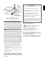
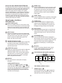
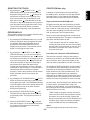
Outdoor Antenna Grounding – If an outside antenna or cable
system is connected to the product, be sure the antenna or
cable system is grounded so as to provide some protection
against voltage surges and built-up static charges. Article 810
of the National Electrical Code, ANSI/NFPA 70, provides
information with regard to proper grounding of the mast and
supporting structure, grounding of the lead-in wire to an
antenna discharge unit, size of grounding conductors, location
of antenna-discharge unit, connection to grounding electrodes,
and requirements for the grounding electrode. See Figure 1.
Lightning – Lightning – Unplug the unit from the wall outlet and
disconnect the antenna or cable system for added protection
during a lightning storm or when it is left unattended and
unused for long periods of time. This will prevent damage to the
product due to lightning and power line surges.
Power Lines – An outside antenna system should not be
located in the vicinity of overhead power lines or other electric
light or power circuits, or where it can fall into such power lines
or circuits. When installing an outside antenna system, extreme
care should be taken to keep from touching such power lines or
circuits as contact with them might be fatal.
Overloading – Do not overload wall outlets, extension cords, or
integral convenience receptacles as this can result in a risk of
fire or electric shock.
Object and Liquid Entry – Never push objects of any kind into
this product through openings as they may touch dangerous
voltage points or short-out parts that could result in a fire or
electric shock. Never spill liquid of any kind on the product.
Servicing – Do not attempt to service this product yourself as
opening or removing covers may expose you to dangerous
voltage or other hazards. Refer all servicing to qualified service
personnel.
Damage Requiring Service – Unplug this product from the wall
outlet and refer servicing to qualified service personnel under
the following conditions:
When the power supply cord or plug is damaged.
If liquid has been spilled, or objects have fallen into the product.
If the product has been exposed to rain or water.
If the product does not operate normally by following the
operating instructions. Adjust only those controls that are
covered by the operating instructions, as an improper
adjustment of other controls may result in damage and will often
require extensive work by a qualified technician to restore the
product to its normal operation.
If the product has been dropped or damaged in any way, and
When the product exhibits a distinct change in performance –
this indicates a need for service.
Replacement Parts – When replacement parts are required, be
sure the service technician has used replacement parts
specified by the manufacturer or have the same characteristics
as the original part. Unauthorized substitutions may result in fire,
electric shock, or other hazards.
Safety Check – Upon completion of any service or repairs to this
product, ask the service technician to perform safety checks to
determine that the product is in proper operating condition.
Wall or Ceiling Mounting – The product should be mounted to a
wall or ceiling only as recommended by the manufacturer.
Heat – The product should be situated away from heat sources
such as radiators, heat registers, stoves, or other products
(including amplifiers) that produce heat.
ENGLISH
IMPORTANT SAFETY INSTRUCTIONS
GROUND CLAMPS
Do not expose the equipment to rain or moisture.
Do not remove the cover from the equipment.
Do not insert an ything into the equipment through
the ventilation holes.
GROUNDING
CONDUCTORS
(NEC SECTION
810-21)
Do not cover the ventilation with any items such
as tablecloths, newspapers, curtains, etc.
POWER SERVICE
GROUNDING
ELECTRODE SYSTEM
(NEC ART 250, PART H)
No open flame sources, such as lighted candles,
should be placed on the equipment.
FIGURE 1
EXAMPLE OF ANTENNA GROUNDING AS PER
NATIONAL ELECTRICAL CODE, ANSI/NFPA 70
When disposing of used batteries, please comply
with governmental regulations or environmental
public instruction's rules that apply in your country
or area.
NEC - NATIONAL ELECTRICAL CODE
NOTE TO CATV SYSTEM INSTALLER:
This reminder is provided to call the CATV (Cable-TV)
system installer's attention to Article 820-40 of the
NEC, which provides guidelines for proper grounding
and, in particular, specifies that the cable ground shall
be connected to the grounding system of the building,
as close to the point of cable entry as practical.
CE marking (only EU version)
This product is in conformity with the EMC
directive and low-voltage directive.
Equipment mains working system
This product complies with household power and
safety requirements in your area.
NOTE:
This equipment has been tested and found to comply
with the limits for a Class B digital device, pursuant to
Part 15 of the FCC Rules. These limits are designed
to provide reasonable protection against harmful interference in a residential installation. This equipment
generates, uses and can radiate radio frequency energy and, if not installed and used in accordance with
the instructions, may cause harmful interference to
radio communications. However, there is no guarantee that interference will not occur in a particular
installation. If this equipment does cause harmful
interference to radio or television reception, which can
be determined by turning the equipment off and on,
the user is encouraged to try to correct the interference by one or more of the following measures:
• Re-orient or relocate the receiving antenna.
• Increase the separation between the equipment
and receiver.
• Connect the equipment into an outlet on a circuit
different from that to which the receiver is connected.
• Consult the dealer or an experienced radio/TV
technician for help.
NOTE: Changes or modifications may cause this
unit to fail to comply with Part 15 of the FCC Rules
and may void the user's authority to operate the
equipment.
-
This Class B digital apparatus complies
with Canadian ICES-003.
Cet appareil numérique de la Classe B est
conforme á la norme NMB-003 du Canada.
4-
ENGLISH
GROUND
CLAMP
ELECTRIC
SERVICE
EQUIPMENT
WARNINGS
ANTENNA
LEAD IN
WIRE
ANTENNA
DISCHARGE
UNIT
(NEC SECTION
810-20)
1
2
3
4
5
6
7
8
9 10 11
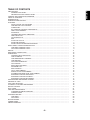
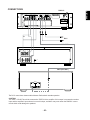
ENGLISH
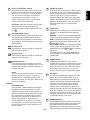
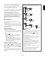
CONTROL AND CONNECTION DIAGRAMS
12
PROFESSIONAL
STEREO CASSETTE DECK / COMPACT DISC PLAYER PMD351
EJECT
PLAY
PLAY PAUSE
STOP
PLAY
DOLBY B-C NR NX PRO
IR
TAPE
PLAY /PAUSE
TAPE
PITCH CONT.
POWER
MEMO
RESET
CASCADE
DUBB
B OFF C
STOP/EJECT
REC/PAUSE
ON OFF
CD
TAPE + CD
TAPE
CD
REV MODE
QUICK REVERSE
ALC
DOLBY NR
AUTOMATIC TAPE SELECT SYSTEM
CD-RW PLAYBACK
HP SELECT
CD PITCH CONT.
TIME
REPEAT
A-B
PROGRAM
13
L
14
15
a
b
16
c
17 18 19 20 21 22 23
d
e
f
L -20 -15 -10 -6
R
B
A
MIC IN
OUT
j
i
D
C
TAPE
IN
L
REPEAT
A-B
MEMO HX-PRO DUBB
REM PROGRAM MP3
TRACK TOTAL
-3
0 -3 1 2 3 4 5 6 7 8 9 10 11 12 13 14 15 16 17 18 19 20
h
CD
OUT
L
R
R
F
CD
TAPE+CD
OUT
L
E
DIGITAL
OUT
G
REMOTE
RC-5
IN
k
l
H
I
24
R
25
g
DOLBY NR BC
R
BALANCE
REC LEVEL
PHONES
m
o
p
n
J
RS232C
EXT
IN
MPX
FILTER
ON OFF
FADER
START
CD
TAPE
CAUTION
OUT
OUT
RISK OF ELECTRIC SHOCK
DO NOT OPEN
DANGER
INVISIBLE LASER RADIATION WHEN OPEN
AVOID DIRECT EXPOSURE TO BEAM
-5-
PRECAUTIONS
WARNINGS CAUTIONS .....................................................................................................................
IMPORTANT SAFETY INSTRUCTIONS ............................................................................................
CONTROL AND CONNECTION DIAGRAMS ..............................................................................................
TABLE OF CONTENTS ...............................................................................................................................
INTRODUCTION .........................................................................................................................................
OPERATING PRECAUTIONS .....................................................................................................................
FEATURES ..................................................................................................................................................
QUICK OPTICAL AUTO REVERSE ...................................................................................................
TAPE AND CD PITCH CONTROL ......................................................................................................
IR RECEIVER .....................................................................................................................................
RC-5 REMOTE CONTROL COMPATIBILITY .....................................................................................
ONE-TOUCH DUBBING .....................................................................................................................
A-B REPEAT .......................................................................................................................................
LOCKABLE REM TRACK TIME MODE ..............................................................................................
ONE-TRACK PLAY .............................................................................................................................
CD-R/CD-RW PLAY ............................................................................................................................
MP3 .....................................................................................................................................................
AUTO CUE CD PLAY .........................................................................................................................
DOLBY NR SYSTEMS ........................................................................................................................
DOLBY HX PRO HEADROOM EXTENSION .....................................................................................
FRONT PANEL CONTROLS AND DISPLAYS .............................................................................................
TAPE DECK CONTROL buttons .........................................................................................................
CD PLAYER CONTROL buttons .........................................................................................................
DISPLAY ......................................................................................................................................................
REAR PANEL CONNECTIONS ...................................................................................................................
OPERATIONS ..............................................................................................................................................
CASSETTE DECK OPERATION ........................................................................................................
TAPE PLAYBACK ...............................................................................................................................
TAPE REWIND/FAST FORWARD ......................................................................................................
TAPE RECORD ..................................................................................................................................
CD PLAYER OPERATION ..................................................................................................................
CD PLAYBACK ...................................................................................................................................
SELECTING THE TRACK ..................................................................................................................
PROGRAM PLAY ................................................................................................................................
MP3 PLAYBACK .................................................................................................................................
CD TO TAPE DUBBING ......................................................................................................................
MANUAL LEVEL TAPE DUBBING ......................................................................................................
AUTOMATIC RECORD LEVEL TAPE DUBBING ...............................................................................
EXTENDED CASCADE OPERATION ................................................................................................
EXTENDED CASCADE PLAYBACK ..................................................................................................
EXTENDED CASCADE RECORDING ...............................................................................................
SYNCHRONIZED RECORDING CONTROL ...............................................................................................
ERASURE OF TAPE ....................................................................................................................................
AUTO TAPE SELECTOR .............................................................................................................................
TO PROTECT VALUABLE RECORDINGS .................................................................................................
RS-232C CONTROL ....................................................................................................................................
RC-5 CODES ...............................................................................................................................................
CARE AND MAINTENANCE .......................................................................................................................
CLEANING EXTERIOR SURFACES ..................................................................................................
COMPACT DISCS ..............................................................................................................................
TROUBLESHOOTING .................................................................................................................................
TAPE DECK ........................................................................................................................................
CD PLAYER ........................................................................................................................................
SPECIFICATIONS .......................................................................................................................................
CONNECTIONS ..........................................................................................................................................
LIMITED WARRANTY .................................................................................................................................
-6-
2
3
5
6
7
7
7
7
7
7
7
7
7
7
7
7
7
7
7
8
8
8
9
11
12
12
12
12
13
13
13
13
14
14
15
16
16
17
17
17
17
18
18
18
18
19
21
22
22
22
23
23
23
24
25
26
ENGLISH
TABLE OF CONTENTS
RC-5 REMOTE CONTROL COMPATIBILITY
Thank you for selecting the Marantz Professional
PMD351 combination Stereo Cassette Deck/CD
Player. Please read these operating instructions
carefully. We recommend that you read the entire
user guide prior to connecting and operating the unit.
It is also recommended that all connections be made
prior to operating the unit. Please refer to this manual
to identify controls and connections for operation of
the unit.
The PMD351 comes equipped with an RC-5 remote
in and out port. Through the use of various remote
control options the major functions of the unit can be
operated via wired or wireless remote control.
ONE-TOUCH DUBBING
OPERATING PRECAUTIONS
A-B REPEAT
The PMD351 allows for the dubbing of a CD to a
tape with one-button start control. This feature allows
you to manually or automatically select the recording
level you desire.
The PMD351 allows you to select two points within
the CD playback mode and repeat the audio playback within these points until a stop command is
issued.
When setting up the equipment ensure that:
• air is allowed to circulate freely around the
equipment,
• the equipment is on a vibration free surface,
• the equipment will not be exposed to interference
from an external source,
• the equipment will not be exposed to excessive
heat, cold, moisture or dust,
• the equipment will not be exposed to direct
sunlight, and
• heavy objects are not placed on the equipment,
• the unit is not exposed to moisture. If so, do not
operate the unit until it has been thoroughly
inspected by a electrically competent technician.
• Do not disconnect AC power by pulling the power
cord. Remove from the outlet by pulling on the
plug only.
LOCKABLE REM TRACK TIME MODE
The CD time display can be toggled between the
various modes of display. In addition, when a display
mode is set, the unit will remain in the selected mode
until you change it. This is particularly useful for
monitoring the audio during performances and
programs.
ONE-TRACK PLAY
The PMD351 can be set to allow for the CD player to
play the selected track and return to the stop mode
rather than continue on to the next track on the CD.
CD-R/CD-RW PLAY
In addition to conventional music CDs and CD-R
(recordable) discs, this player can also play CD-RW
(rewritable) discs. It can also play unfinalized discs
that cannot be played by regular CD players.
FEATURES
QUICK OPTICAL AUTO REVERSE
In addition to the normal tension reversing circuitry,
the PMD351 tape transport also employs optically
sensed quick auto reverse circuitry. This circuitry
reacts to the clear areas of the tape, usually the
leader tape, and when detected, will reverse the
direction of the tape transport. This process minimizes the loss of signal being recorded or played
back. This reverse process applies to all tape playback and recording modes, including auto reverse
and continuous mode.
MP3
This player can play discs containing MP3 files.
AUTO QUE CD PLAY
The CD player on the PMD351 contains an Auto
Que feature. This feature allows the CD player to
advance to the beginning of the audio within the track
rather than start from the track start flag. This feature
helps to minimize the silence at the beginning of a
CD track playback.
TAPE AND CD PITCH CONTROL
DOLBY NR SYSTEMS
The PMD351 tape player and CD player both allow
for adjustment of the playback pitch from -12% to
+12%. The feature is particularly useful for adjusting
the unit playback pitch to allow you to tune the
PMD351 to accompanying instruments and choirs.
The Dolby Noise Reduction systems compress and
amplify the tape during recording in order to raise the
signal-to-noise ratio on the tape. During playback,
these signals are expanded and attenuated by the
same amount in order to regain the original dynamic
range of music. An additional result of this expansion
and attenuation is that the noise floor of the recording
is reduced significantly. Dolby B typically reduces
noise by 10dB. Dolby C typically reduces noise by
20dB.
IR RECEIVER
The PMD351 is equipped with an IR receiver for use
with remote control Model RC330 (not supplied)
available from Marantz Professional.
-7-
ENGLISH
INTRODUCTION
The Dolby HX PRO system monitors the total amount
of effective bias during recording and instantaneously
compensates for any excess bias by reducing the
deck’s bias signal level accordingly. The system
operates independently on each channel. HX PRO is
unlike a noise reduction system because it functions
only during recording and no decoding is required.
Therefore a tape recorded with the HX PRO system
can be played back on any other cassette deck while
retaining the benefits of HX PRO.
FRONT PANEL CONTROLS
AND DISPLAYS
1
2
3
4
5
CASSETTE TAPE HOLDER
This section holds the cassette tape for tape Play
and Record functionality. Tapes that have the
record protect knock-out removed will not enter
into the record mode.
MEMO button
Press the MEMO button to store a memory point
into the counter memory. Once this point is set,
the tape deck will rewind or fast forward until it
reaches this point in the tape and will stop. To
cancel the memory control, press the MEMO
button again.
7
RESET button
Press the RESET button to reset the current tape
counter reading from its existing point to “0000”
8
Power switch button
Push the POWER switch in to turn power to the
unit on and off. When power is turned off, all past
settings are removed from memory and the unit
returns to its default setting upon the next power
up.
EJECT button
Press the eject button to open the cassette tape
holder. The EJECT button will not function unless
the tape deck is in the stop mode. Thus, if the
power is turned off without hitting the STOP
button, the door may not open.
6
9
DUBB button
Press the DUBB button to engage the tape
transport into the dubbing mode from the CD
player. Once the DUBB button is pressed, the
CD player will copy directly to the tape deck.
REC indicator
Displayed when the tape deck is in the Record
mode. When the REC indicator is flashing, this
indicates the tape deck is in the Record Pause
mode.
10
REC/PAUSE button
Press the REC/PAUSE button to engage the
tape transport into the record pause mode. In this
mode, the tape deck is armed to begin recording.
The tape record mode can be engaged by
pressing the forward play or reverse play buttons.
11
IR sensor
Sensor for receiving infrared remote control
signals. Model RC330 IR control emitter is
available from Marantz Professional.
12
TAPE DECK AND CD PLAYER CONTROLS
TAPE PITCH control
Rotate the TAPE DECK pitch control to adjust the
tape deck playback pitch from -12% to +12%.
While the control is in the center detent position,
the tape deck is at normal (0% pitch variance)
speed. This control has no effect on the tape
pitch during the record mode.
PLAY PAUSE
STOP
PLAY
DISPLAY
See next section for description of display
elements.
PLAY
TAPE
TAPE COUNTER buttons
The MEMO button 6 and RESET button 7
control the tape counter (DISPLAY a ). The tape
counters are only approximate measurements of
minutes and seconds and are not intended for
timing-critical applications. They are most accurate with 60 minute tapes.
a
TAPE DECK CONTROL buttons
a
REWIND button
Press the REWIND button
to engage the
tape transport into fast rewind mode from the
right (take-up) to the left (supply) reels.
-8-
ENGLISH
DOLBY HX PRO HEADROOM EXTENSION
mode, this function is used along with the NEXT/
to select
SEARCH FAST FORWARD button
the desired tracks to be played.
PLAY
Note:
Automatic search operations cannot operate on
the Tape and CD at the same time.
TAPE
b
b
c
d
e
g
PLAY/PAUSE button
Press the PLAY/PAUSE button
to change
the CD player mode from CD play to CD pause
or from CD pause to CD play.
h
NEXT/SEARCH FAST FORWARD button
When the CD player is in the play or pause
mode, pressing the NEXT/SEARCH FAST
FORWARD button
will skip forward one
track for every time the control button is pushed.
Keeping this control depressed causes the unit
to advance (scan) into the track. The track time
display will show your current location within the
song. During the program mode, this function is
used along with the PREVIOUS/SEARCH
REVERSE button
to select the desired
tracks to be played.
i
STOP/EJECT button
Press the STOP/EJECT button
to stop the
CD Player while in the play mode. Press the
STOP/EJECT button
while in the Stop
mode to open the door and eject the disk.
During the program mode, the STOP/EJECT
button
will cancel the current program as
long as the CD player is in the Stop mode.
REVERSE PLAY button
Press the REVERSE PLAY button
to engage
the tape deck into the reverse play function.
c
STOP button
Press the STOP button
to cancel all current
operations of the tape deck.
d
FORWARD PLAY button
Press the FORWARD PLAY button to engage
the tape deck into the forward play function.
Indicator light in the button is lit during forward
play, flashing during stop or pause.
e
FAST FORWARD button
Press the FAST FORWARD button
to
engage the tape transport into the fast forward
wind mode from the left (supply) to the right
(take-up) reels.
STOP/EJECT
PLAY /PAUSE
CD
f
g
h
HP SELECT switch
The HP SELECT switch (Headphone selector
switch) is used to switch the headphone output.
14
HEADPHONES jack
The HEADPHONES jack is used to allow
monitoring of the Tape, CD or Tape/CD Mix
through headphones. This jack requires that a
1/4" headphone jack connection be made and
the desired source can be selected by the HP
SELECT switch located directly above the
headphone input jack.
15
COMPACT DISC tray
The COMPACT DISC tray is used to hold the
desired CD for playback.
i
CD PLAYER CONTROL buttons
f
13
PREVIOUS/SEARCH REVERSE button
When the CD player is in the play or pause
mode, press and release the PREVIOUS/
SEARCH REVERSE button
to skip back to
the beginning of the current track and then skip
one track for every time the control button is
pressed and released. Keeping this control
pressed for more than 1/2 a second causes the
unit to retreat (backward scan) within the track.
The track time display will show your current
location within the song. During the program
-9-
ENGLISH
PLAY PAUSE
STOP
PLAY
CD PITCH CONTROL buttons
By pressing the CD player PITCH CONTROL
buttons, you can adjust the CD player playback
pitch from -12% to +12% in 0.1% increments.
You can return the CD player to the normal
speed position by pressing the center “0”
control. Pressing the center “0” control again
returns it to the previous settings.
CAUTION - When the CD pitch control is used,
digital lock may not occur with some D/A
converters connected via the CD DIGITAL OUT
jack E .
17
18
DOLBY NR switch
The DOLBY NR switch allows for the encoding
or decoding of Dolby B or C Noise Reduction.
When recording with Dolby Noise Reduction on,
select the type (B or C) of noise reduction
desired and place the switch in the appropriate
position. When playing a tape with Dolby Noise
Reduction encoded onto it, place this switch in
the same position (B or C) in which it was
recorded.
19
TIME button
By pressing the TIME button, you can adjust the
CD player time displayed from the following
formats.
NORMAL - Displays the time elapsed within the
current track being played. No special indicator.
REM - Displays the remaining time left of the
current track being played. REM indicator (item
l in the display) is lit.
TOTAL REM - Displays the total time remaining
on the current disk being played. TOTAL and
REM indicators (items k and l in the display)
are both lit.
The TIME button can be toggled between the
various displays by pressing the TIME button
multiple times.
20
REPEAT button
By pressing the REPEAT button, you can
program the CD player to repeat all tracks of the
current disk. When there is a CD play program
that is currently active, this function will repeat
the current program selections. To clear this
function, press the repeat control button again.
21
A-B button
The A-B button allows you to repeat a specific
section in the current CD track that is being
played. When this control is pressed the first
time, the A-B indicator flashes and this position
on the track is noted as the start or A point.
When this control is pressed again, the A-B
indicator is lit and this position on the track is
noted as the end or B point. After setting the end
point, the CD player returns to the start point (A)
and plays until it reaches the end point (B). The
CD player will repeat this function until the stop
or REPEAT button is press again.
22
PROGRAM button
The PROGRAM button will place the CD player
into the program entry mode or the single track
play mode. When the PROGRAM button is
pressed once, the CD player enters the program
entry mode and the program indicator will begin
REVERSE MODE switch
The REVERSE MODE switch allows you to set
the automatic tape direction operation of the
tape transport during playback, normal recording or dubbing. The four positions of this switch
are as follows;
One-way mode.
In this position, the tape will play or record one
side of the tape and stop.
Two-way mode.
In this position, the tape will play or record both
sides of the tape and stop.
Continuous mode.
In this position, the tape will play in a continuous loop until the stop command is given. In the
record mode, the tape will record both sides of
the tape and stop.
Notes:
Quick reverse operation will only occur after the
transport has been moving for 15 seconds.
Before that time, it takes approximately four
seconds to reverse. One second of audio is lost
during quick reverse.
CASCADE
CASCADE mode:
In this position, multiple Marantz Professional
tape decks that are equipped with the “EXT”
cascade connector can be looped together to
allow for extended cascade playback or recording. In this mode, the tape will play or record
both sides of the tape; and, at the end of the
tape on the first deck, a command will be
issued causing the next deck in line to begin
cascade play or record. This will continue until
the end of the last tape on the last deck of the
loop is reached.
- 10 -
ENGLISH
16
23
24
25
ALC switch (AUTOMATIC LEVEL CONTROL)
The ALC switch allows for automatic control of
the source level during recording. When this
switch is set to the OFF position, the level of
recording is controlled by the manual record
level adjustment. When this control is set to the
ON position, the record level is set automatically.
In this position, the manual record level adjustment has no effect on the recording.
f
g
REPEAT indicator is displayed when the CD
player is in the repeat mode.
MANUAL RECORD LEVEL control
The MANUAL RECORD LEVEL control allows
you to adjust the record level up or down during
recording.
h
Level indicators display the record or playback
signal levels of the tape deck.
i
MEMO indicator is displayed when the tape
deck memory function is turned on.
RECORD BALANCE control
The RECORD BALANCE control allows for the
adjustment of the record level between the left
and right channels. By using a Phillips-type
screwdriver, you can adjust this balance control
between Left (Counterclockwise) and Right
(Clockwise).
j
TRACK indicator
Lit as title for several CD track functions.
k
TOTAL indicator
When the TOTAL indicator and the REM indicator
are both displayed, the track time indicator f
represents the total remaining time of the CD.
l
REM indicator
When the REM indicator is displayed and the
TOTAL indicator is not displayed, the track time
indicator f represents the total remaining time
of the track being played.
m
PROGRAM indicator is displayed to indicate that
the CD player is in the program mode. The
indicator flashes during the program play entry
mode. This indicator can be turned on and off by
pressing the program button.
n
MP3 indicator is displayed when an MP3 file is
recognized.
o
A-B indicator is displayed when the tape deck is
in the A-B repeat mode. When the A-B indicator is
flashing, this indicates standby for the setting of
point B.
p
TRACK number indicator (1 through 20),
displays the track numbers on the CD. When in
the program mode, the tracks programmed are
displayed. Upon completion of playing a track,
the number will disappear. When playing a CD
with more than 20 tracks on it, the “=>” indicator
is displayed.
DISPLAY
a
b
c
d
e
TRACK time indicator displays the playing time
of the CD in four digits, representing minutes and
seconds. This display typically represents
elapsed time of the track being played. When the
REM indicator is displayed, the time shown
represents the remaining time of the track being
played. When the TOTAL REM indicator is
displayed, this represents the total remaining time
of the CD or of the program currently being
played. In the stop mode, the total playing time of
the CD is displayed. The flashing colon, “:”
indicates that the CD pitch control is in use.
Tape counter display indicates the amount of
tape that has been transported across the head
in digits.
Dolby NR B C indicators display the type of
Dolby noise reduction that has been selected.
Level indicators display the record or playback
signal levels of the tape deck.
HX PRO indicator is displayed showing HX
PRO is activated.
DUBB indicator is displayed when dubbing
from the CD player to the tape deck.
TRACK number indicator displays the track
number that the CD has identified in play or
pause mode. In the stop mode, the number of
tracks on the entire CD or the numbers of the
tracks programmed to play are displayed. When
the TRACK number indicator is flashing, it
indicates that the CD player is in the single-track
play mode. When in this mode, the CD player
will play the selected track and go to the stop
mode.
- 11 -
ENGLISH
to flash. Pressing the PROGRAM button again
will place the CD player in the single track play
mode, and the track indicator will begin to flash.
Pressing the PROGRAM button again will return
the CD player to the normal play mode.
A
B
MIC (MICROPHONE) INPUT jack
For use with microphones as the input source
into the tape deck. When microphones are
installed into these jacks, the line inputs are
automatically switched off and only the microphone signal is input into the unit. For mono
recording, insert the microphone into the L (Left)
jack.
TAPE IN jacks
These RCA jacks should be connected to the
LINE OUTPUT of your source.
C
LINE OUT (TAPE, CD, TAPE+CD)
These RCA jacks should be connected to the
appropriate INPUT of your PA or monitoring
system.
D
MPX FILTER switch
When recording FM broadcast with Dolby NR,
set this switch to the ON position.
E
F
I
FADER START jacks
Upon receiving a dry switch contact closure on
the jack connections, the CD Player can be
switched in and out of play and play/pause
mode. The Tape deck can be switched in and
out of play and stop or the record and stop
mode.
J
POWER CORD
120VAC input power connector.
Operations
The following operating procedures are based on the
assumption that the power switch is set to the ON
position and that all input and output connections
have already been made. For examples of input and
output connections, please refer to the section in this
manual marked “Connections”.
CASSETTE DECK OPERATION
TAPE PLAYBACK
DIGITAL OUTPUT jacks (SPDIF)
This RCA jack outputs the digital signal of the CD
Player. Connect this jack to other SPDIF digital
inputs such as a D/A converter or digital sound
processor or amplifier with SPDIF digital inputs
such as the Marantz Professional CD Recorder.
Digital signals are not output while MP3 files are
playing.
RC-5 REMOTE CONTROL jacks
These RCA jacks are used with Marantz Professional infrared or wired remote accessories to
provide remote control operation of the PMD351.
These jacks can be serially linked to provide
serial remote control operation of multiple RC-5
equipped products as well.
G
REMOTE EXT (extension) jacks
Connection with other Marantz Professional
components equipped with REMOTE EXT. jacks
will allow for extended cascade operation of
several units.
H
RS-232C connector
Using serial communication, a host device can
control this unit.
• The RS-232C host can control all functions
of the PMD351 externally
• The PMD351 automatically transmits status
data when status is changed.
• The PMD351 will respond to a status request
by transmitting the associated status data
1. Open the cassette holder by pressing the eject
button. Load a cassette tape into the cassette
holder and close. The
indicator on the play
control button will begin to flash.
2. Set the Dolby Noise Reduction control switch to
the same position as the tape was originally
recorded in (i.e. tapes recorded with Dolby B
noise reduction need to have this switch in the
Dolby B position, tapes recorded with Dolby C
noise reduction need to have this switch in the
Dolby C position, and tapes recorded without
Dolby Noise Reduction need to have this control
set to the Off position).
3. Set the reverse mode control switch to the
desired position.
4. Press the
play control button to begin play-
back in the forward direction. Press the
play
control button to begin playback in the reverse
play direction. When the tape enters into the
playback mode, the indicator on the play control
button will change from the flashing mode to a
constant on mode to indicate playback is operating.
5. Pressing the stop control button will stop the tape
transport during playback.
- 12 -
ENGLISH
REAR PANEL CONNECTIONS
Regardless of the direction that the tape transport is
currently in, pressing the
(Fast Forward) control
button will place the tape transport in the high speed
fast forward mode and the tape will advance quickly
(Rewind) control
from left to right. Pressing the
button will place the tape transport in the high speed
rewind mode and the tape will retract quickly from
right to left. In either the fast forward or the rewind
mode, the tape transport will continue to fast forward
or rewind until the stop control button is pressed or the
end of the tape is reached.
REVERSE PLAY button
to begin recording in
the reverse direction. When the tape enters into
the playback mode the REC indicator and the play
control button indicator will change from the
flashing mode to the constant on mode. This
indicates the tape transport is in the record mode.
8. To pause the tape transport during recording,
press the REC/PAUSE button. Press the play
)to resume recording.
control button ( or
9. Pressing the STOP button
transport during recording. Pressing the
Note:
Automatic search operations cannot operate on the
Tape and CD at the same time.
rewind button in the
play control button will begin to flash. (If you
wish to change the tape direction, press the
play control button and then press the
stop
control button).
3. Set the REVERSE MODE switch to the desired
position.
4. Set the ALC control to the desired position, on or
off.
5. Press the REC/PAUSE button. The REC indicator
will begin to flash indicating the tape transport is in
the record pause mode.
7. Press the FORWARD PLAY button
to begin
recording in the forward direction. Press the
CD PLAYER OPERATION
CD PLAYBACK
2. Set the DOLBY NR switch to the position that you
want to record the tapes' noise reduction in (i.e.
tapes to be recorded with Dolby B noise reduction
need to have this switch in the Dolby B position,
tapes to be recorded with Dolby C noise reduction
need to have this switch in the Dolby C position,
and tapes to be recorded without Dolby Noise
Reduction need to have this control set to the Off
position). When recording FM broadcast with
Dolby Noise reduction on, set the MPX FILTER
switch (on the back of the unit) to the On position.
6. If the ALC control is in the Off position, use the
MANUAL RECORD LEVEL control to adjust the
input signal to the desired recording level.
play/record direction or
the
fast forward button in the
play/record
direction will cause the unit to return to the
position at which recording began.
TAPE RECORD
1. Open the cassette holder by pressing the EJECT
button. Load a recordable cassette tape into the
cassette holder and close. The
indicator on the
will stop the tape
1. Open the compact disc tray by pressing the STOP/
EJECT button
. Load a compact disc onto the
compact disc tray and close the tray by gently
pushing the front of the compact disc tray or by
pressing the STOP/EJECT button
. The CD
player display will show the general data of the
current CD.
2. To begin playback of the compact disc, press the
PLAY/PAUSE button
. The
indicator in the
PLAY/PAUSE button will illuminate. The display
will show the data for the first track and the track
will begin to play.
3. To pause the CD during playback, press the PLAY/
PAUSE button
. The display will remain in the
current position and the
indicator in the PLAY/
PAUSE button will begin to flash. Pressing the
PLAY/PAUSE button
will resume normal
playback from the point that the CD player was
paused.
4. Upon completion of playback of the last track in
the disc, the CD Player will return to the stop
mode. You can also stop the CD playback by
pressing the STOP/EJECT button
once.
Pressing the STOP/EJECT button
again will
cause the CD tray to open.
- 13 -
ENGLISH
TAPE REWIND/FAST FORWARD
1. By pressing the
CD-NEXT or the
CDPREVIOUS buttons, you can select the track to
be played. Each press of the
CD button will
advance the CD player to the beginning of the
next track and enter into the play/pause mode.
Each press of the
CD button will cause the
CD player to skip to the beginning of the previous
track and enter into the play/pause mode. Pressing the CD PLAY/PAUSE button will resume
playback at the beginning of the selected track.
In addition to conventional music CDs and CD-R
(recordable) discs, this player can also play CD-RW
(rewritable) discs. It also supports the unfinalized
discs that cannot be played by regular CD players.
Playing unfinalized CD-R/CD-RW discs
CD players normally play only those discs on which
the TOC information* has been recorded. This means
that in order for a CD player to play a CD-R/CD-RW
disc with music recordings, the disc has to be "finalized" by writing the TOC information onto it.
PROGRAM PLAY
This procedure allows you to program selected tracks
for playback in the order you desire.
Discs for which this finalizing job has not been done
are called unfinalized discs. This player is designed to
play these unfinalized discs as well.
1. By pressing the PROGRAM button once, you will
place the CD player into the programming mode
for playback. Once the PROGRAM button is
pressed, the PROGRAM indicator in the CD
display will begin to flash. This indicates the CD
player is in the program entry mode.
*"TOC" stands for the table of contents which
contains the total number of tracks, the total play
time and other such information on the disc. This
information is recorded on the inner circumference area of the disc.
2. By pressing the
CD NEXT or the
CD
PREVIOUS buttons, you can select the track to
be programmed. Each press of the
CD button
will advance the CD player to the beginning of the
next track. Each press of the
CD button will
cause the CD player to skip to the beginning of
the previous track. When the desired track
number has been selected, leave the CD player
untouched for approximately 1.5 seconds and the
selected track will be stored in the playback
program. Continue this procedure until all desired
tracks (20 tracks maximum) have been programmed.
3. By pressing the PLAY/PAUSE button
, the CD
player will exit the program entry mode and enter
the program play mode. The PROGRAM indicator
in the CD display will be lit and steady and the CD
player will begin to play in the order selected
during the programming.
Precautions for unfinalized CD-R/CD-RW discs
Take care not to scratch or dirty the area near the
innermost circumference of unfinalized CD-R/CD-RW
discs. Scratches, dirt or other abnormalities in this
area may make it impossible for the disc to be read.
On unfinalized CD-R/CD-RW discs recorded using a
CD recorder for audio applications, provisional TOC
information is recorded in the PMA area* which is
further inside from the TOC information area. This
player supports unfinalized discs by reading the
information in the PMA area, but because this area is
extremely narrow, any scratches, dirt or other abnormalities here make it impossible for discs to be read.
On some discs, this area may be very difficult to read.
In cases like this, use the disc after using a CD
recorder to do the finalizing. It is recommended that
the finalizing be done before scratches or dirt makes it
hard for the discs to be read.
4. By pressing the STOP/EJECT button
, the
CD player will stop playing but will remain in the
program/play mode. The program will remain in
memory.
5. When the STOP/EJECT button
is pressed
while the CD player is in the stop mode and while
the program is still engaged, the memorized
program will be cleared.
*"PMA" stands for program memory area and it
refers to the area where the provisional contents
information, such as the number of tracks and
play times recorded on the CD-R/CD-RW discs, is
recorded. Discs cannot be played by this player
unless the PMA has been recorded properly.
Notes:
This player supports the discs which have been
- 14 -
ENGLISH
CD-R/CD-RW disc play
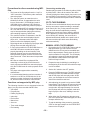
SELECTING THE TRACK
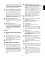
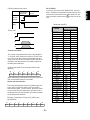
Example play sequence as displayed in Windows Explorer:
The player can play only those discs recorded in the
music format (CD-DA) or using MP3 files.
Album 02
Album 03
aaaa03.mp3
aaaa04.mp3
aaaa05.mp3
aaaa06.mp3
If there is not much recording time, it may be difficult
for the data to be read, and it may cause an error.
When the player is to play a CD-RW disc or
unfinalized CD-R/CD-RW disc, it automatically
recognizes the type of disc and changes some of its
internal settings to suit the disc concerned. For this
reason, the disc reading process will take a little
longer compared to regular music CDs or CD-R
discs.
Album 04
Album 05
bbbb07.mp3
bbbb08.mp3
Album 06
MP3 PLAYBACK
Album 07
dddd11.mp3
dddd12.mp3
This player can play CD-R/CD-RW discs as well as discs
including MP3* files.
* “MP3” refers to music data which has been
compressed by a file format known as “MPEG-1 Audio
Layer 3.” Files with the “.mp3” or “.MP3” extension
are called MP3 files.
eeee13.mp3
eeee14.mp3
Album 08
Album 09
wwww.wav
xxxx.wav
Album 10
ffff15.mp3
MP3 FILE PLAYBACK
PLAYING ALBUMS IN SEQUENCE
AAAA01.mp3 Root
BBBB02.mp3 Album 01
1. As with a music CD, place the disc recorded using
the MP3 files on the disc tray and retract the disc
tray.
2. Press the
button.
Play now starts in sequence from the first album
on a folder-by-folder basis* (see Example play
sequence next column).
* With a disc recorded with MP3 files, it takes
about 40 seconds after the player’s power has
been turned on for the player’s system to be
switched before initial play.
gggg16.mp3
gggg17.mp3
Play up to 8 hierarchical levels possible.
• The dotted line with an arrow (
) indicates the
sequence in which the MP3 albums and tracks are
played.
• Album 01 to album 10
In the example shown, this CD-ROM has 10 albums
(folders) but albums 03 and 08 are not MP3 files and
so cannot be played.
• AAAA01.mp3 to gggg17.mp3
In the example shown, this CD-ROM has 17 tracks
starting with track "01" and ending with track "17."
Selecting and playing albums (folders)
Select the desired album (on a folder-by-folder basis*)
using the
or
button. Play now starts in
sequence from the selected album. The album number
appears on the display. (AL xxx is displayed at f and
the track at e .)
*Those items among the display information which were
not recorded are skipped. Only the recorded items are
displayed.
• Only those files with the ".mp3" extension are played;
all other files with the .wav, .jpg, .doc and other
extensions are skipped.
• Album 01 is allocated even when there are no files in
the root.
• The sequence may differ from the one that appears
on the personal computer. It may also differ
depending on the writing software program.
- 15 -
ENGLISH
recorded by any recorder that complies with the
"Orange book" of CD-R/CD-RW standards.
Precautions for discs recorded using MP3
files
Random play proceeds on an album by album (folder
by folder) basis. When all the tracks of the album
currently playing have been played, play moves on to
the next album in the sequence. During random play,
the 1-track repeat and A-B repeat functions cannot be
used.
• The format of the files played have the “.mp3” or
“.MP3” extension. Files with any other extension
cannot be played.
• The Joliet file system, an extension to the
ISO9660 file format, is supported as the write
format. Both mode 1 (CD-ROM) and mode 2
(CD-ROM XA) are supported. MP3 file discs
recorded using packet writing cannot be played.
• The recommended MP3 file sampling frequency is
44.1 kHz and the bit rate is 128 kbps. The sound
may be interrupted when playing files with any
other sampling frequency and bit rate.
• The maximum number of characters in the ID3
tag information that can be displayed by this
player is 32. Characters other than alphanumerics will not be displayed properly.
• Digital signals are not output from the player while
playing discs recorded using MP3 files.
• It may not be possible for CD-R/CD-RW discs on
which MP3 files were recorded to be played
properly depending on the environment of the
personal computer used to record the files, the
writing software program, and the CD-R/CD-RW
discs concerned. Check the external components
used.
• MP3 files on mixed CDs or enhanced CDs
containing a mixture of the CD-DA format for
music purposes and MP3 files cannot be played.
Only the CD-DA format for music purposes will be
played.
• This player also supports discs created by
multisessions.
• It is recommended that the maximum number of
sessions on a CD-R or CD-RW disc be 10; the
maximum number of albums for all sessions be
20; and the maximum number of files be 200.
CD TO TAPE DUBBING
The CD source can be dubbed directly onto the tape
deck by two means: manual recording or automatic
level control (ALC On). During manual record dubbing, the level desired is adjusted by manually
adjusting the record level control. After the desired
level is adjusted, you then release the tape deck to
record. During ALC dubbing, the record level is
adjusted automatically based on the peak levels of
the source and the tape deck enters the dubbing
mode automatically.
MANUAL LEVEL TAPE DUBBING
1. By pressing the CD STOP/EJECT button and the
tape eject button you can load the CD to be
dubbed onto the CD tray and a recordable tape
into the tape transport. Gently press the front of
each mechanism to close them. The CD display
will register the general CD data and the tape
play indicator located inside of the tape PLAY
button will begin to flash.
2. Prepare the tape for dubbing by rewinding it to
the beginning of the first side onto which the tape
is to be recorded.
3. Set the ALC switch to the OFF position.
4. Press the DUBB button once. The REC indicator
will begin to flash; the DUBB indicator will light;
and the CD player will enter play mode. At this
point, you can adjust the record level control to
achieve the desired record level.
Functions not supported by MP3 play
The following functions are not supported when the
player is to play discs recorded with MP3 files.
• A-B repeat
• Program play
• Delete program play
• Index skip
• End monitor
• Manual cue
• Auto cue
• Time mode changes
• End warning
5. After adjusting the record level, press the DUBB
button again. The CD player will return to the stop
mode and the tape transport will enter into the
record mode. After approximately five seconds
the CD player will enter the playback mode and
begin to play the first track, dubbing it onto the
tape.
6. When either the CD transport or the tape transport have reached the end and stopped, the other
transport will also stop.
7. To end the dubbing during a session, press the
STOP on the tape transport or the STOP/EJECT
button on the CD player.
- 16 -
ENGLISH
Concerning random play
1. By pressing the CD STOP/EJECT button and the
tape eject button, you can load the CD to be
dubbed onto the CD tray and a recordable tape
into the tape transport. Gently press the front of
each mechanism to close them. The CD display
will register the general CD data and the tape play
indicator located inside of the Tape PLAY button
will begin to flash.
2. Prepare the tape for dubbing by rewinding it to the
beginning of the first side onto which the tape is to
be recorded.
3. Set the ALC switch to the ON position.
4. Press the DUBB button once. The REC indicator
will begin to flash; the DUBB indicator will light;
and the CD player will enter play mode. The CD
will automatically begin to search the source for
the peak level. This procedure could take as long
as five minutes to complete. Once the peak level
has been determined, the record level for dubbing
will be set automatically.
5. After the record level has been set, the tape
transport will enter into the record mode. After
approximately five seconds, the CD player will
enter the playback mode and begin to play the
first track, dubbing it onto the tape.
6. When either the CD transport or the tape transport
have reached the end and stopped, the other
transport will also stop.
EXTENDED CASCADE OPERATION
By using the cascade feature on the PMD351 with
another PMD351 or other Marantz Professional
products offering the cascade feature, several units
can be connected to supply long playback or recording
functionality.
EXTENDED CASCADE PLAYBACK
1. Refer to the user guide of the other components to
assure that all connections and switch settings are
set correctly.
2. Assure that the “ EXT” jack on the rear of all units
are connected. Starting with the first unit to
operate, connect the “EXT” out jack to the “EXT”
input on the second unit to operate. Continue this
set-up procedure until all units that are to operate
in the cascade mode have the “EXT” control jacks
serially linked together.
3. Set the PMD351 reverse mode control switch to
the CASCADE position.
4. Begin the playback of the first source by pressing
the play control button. The unit will enter playback
mode. After the first source has completed playback, the next component in the cascade will
begin playback. This will continue until the last unit
linked in the cascade chain has completed playback and entered the stop mode.
5. To exit the cascade playback mode, press the stop
control button of the source machine currently in
playback mode.
EXTENDED CASCADE RECORDING
7. To end the dubbing during a session, press the
STOP on the tape transport or the STOP/EJECT
button on the CD player.
Notes:
When dubbing is started with a program of CD tracks,
the tracks are dubbed in the order of which the original
playback was programmed. For assistance in programming playback, see PROGRAM PLAY.
The CD peak level that is detected during ALC level
dubbing may vary from one recording to another;
however, the effect will be minimal. When recording
with the reverse mode control set to the two-way or
the continuous mode, there may be an interruption in
recording of approximately one second during the
optical reversing of the tape transport.
1. Refer to the user guide of the other components to
assure that all connections and switch settings are
set correctly.
2. Assure that the “EXT” jack on the rear of all units
are connected. Starting with the first unit to
operate, connect the “EXT” out jack to the “EXT”
input on the second unit to operate. Continue this
set-up procedure until all units that are to operate
in the cascade mode have the “EXT” control jacks
serially linked together.
3. Set the PMD351 reverse mode control switch to
the CASCADE position.
4. Place all components that are linked together in
the cascade mode into the record pause mode.
- 17 -
ENGLISH
AUTOMATIC RECORD LEVEL
TAPE DUBBING
middle of an operation, the cassette tape remains
loaded and it may be impossible to eject. In such a
case, turn the power on; enter PLAY mode; press
STOP; and then eject the tape. The same caution as
above applies in case of power failure. To prevent
damage, never attempt to force the removal of a
cassette while the power is off.
6. To exit the cascade record mode, press the stop
control button of the source machine currently in
record mode.
ERASURE OF TAPE
When a program source is recorded onto a tape, the
previously recorded sound is erased automatically and
replaced with the new recording. If you wish to erase a
tape without recording, set the REC LEVEL control to
the minimum (counterclockwise) position and let the
tape travel in the Record mode.
Notes:
If all components have not been set up correctly (tape
or CD loaded, record pause armed, etc.) the cascade
function will stop upon reaching this source machine.
If the cascade function is started with the tape first, the
PMD351 will go to CD playback next and then to the
next component. If the playback is started with the CD
first, the PMD351 will play the CD then go to the next
component.
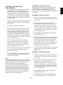
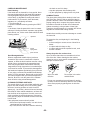
AUTO TAPE SELECTOR
This unit is equipped with an auto tape selector which
automatically sets the bias and equalizer level using
the detection holes provided in the cassette shell. The
bias and equalizer level are automatically set according to the type of cassette as follows.
Metal tape
detection holes
Before beginning the cascade record function, hand
wind the tape leaders so that no leader is showing.
This will minimize interruptions in your recordings.
SYNCHRONIZED RECORDING CONTROL
The PMD351 is capable of connecting with other
Marantz RC-5 based products to allow for synchronized start of the product recording through the
starting of the play function of the CD player or the
tape transport of the PMD351. By connecting the RC5 output jack to the RC-5 input jack of another
Marantz recorder, the PMD351 will issue a command
for the recording to start as soon as the play control
button is pressed on the PMD351. Pressing the stop
or the stop/eject control button on the PMD-source
deck will place the attached component into the
record/pause mode.
HIGH/Position tape
detection holes
•Normal tapes
•HIGH/Position tapes
•Metal tapes
During the cascade recording mode, the PMD351 can
be attached to other Marantz RC-5-based decks for
the purpose of small scale duplication of the dubbing
source. This is accomplished by linking the RC-5
output connector to the RC-5 input of the recording
deck and placing the PMD351 reverse mode control
switch into the cascade position.
Notes:
CAUTION
If you must stop playback or recording in the middle of
button first,
a tape, be sure to press the STOP
then turn the power off. If the power is turned off in the
EQ; l2µS,
EQ; 7OµS,
EQ; 7OµS,
Bias; Low
Bias; High
Bias; Metal
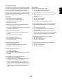
TO PROTECT VALUABLE RECORDINGS
In the record mode,
information previously
recorded on the tape will
automatically be erased.
To prevent this from
happening, use a small
screwdriver to break out
one or both safety tabs.
It is possible to restore the recording capability of
either side of the cassette by covering the opening
with clear adhesive tape.
- 18 -
ENGLISH
5. Begin the recording of the first source by pressing
the play control button. The unit will enter record
mode. After the first source has completed recording, the next component in the cascade will begin
recording. This will continue until the last unit
linked in the cascade chain has completed
recording and entered the Stop mode.
Hand shake flow charts for control commands:
PMD351
Host sends a command that causes a
change in PMD351 status.
PMD351
Control commands:
CD command
Typical Host
Received Command
Status Command
• The RS-232C host can control all functions of the
PMD351 externally
• The PMD351 automatically transmits status data
when status is changed.
• The PMD351 will respond to status requests by
transmitting the associated status data.
Request Command
ENGLISH
RS-232C control
Connect a male (D-Sub 9 Pin) to female (D-Sub 9 Pin)
straight cable for RS-232C external control by host
equipment.
Typical Host
Received Command
TAPECommand
0
1
"@12000"+CR
"@12001"+CR
"@11800"+CR
"@11801"+CR
2
3
"@1202"+CR
"@12003"+CR
"@11802"+CR
"@11803"+CR
4
5
"@12004+CR
"@12005+CR
"@11804"+CR
"@11805"+CR
6
7
"@12006"CR
"@12007"+CR
"@11806"+CR
"@11807"+CR
Commands Requesting Status
"@12008"+CR
"@12009"+CR
"@120011"+CR
"@120015"+CR
"@120029"+CR
"@120032"+CR
"@120033"+CR
"@120037"+CR
"@120038"+CR
"@12003801"+CR
"@120039"+CR
"@12003901"+CR
"@120041"+CR
"@120043"+CR
"@120045"+CR
"@120048"+CR
"@120049"+CR
"@120050"+CR
"@12005001"+CR
"@120052"+CR
"@12005201"+CR
"@120053"+CR
"@120054"+CR
"@120059"+CR
"@11808"+CR
"@11809"+CR
The following Request Commands from the host are
received by the PMD351, then the status code is
transmitted to the host.
8
9
Time
Recall
Repeat
Next
Previous
Pitch Reset
Pitch Up Start
Pitch Up Stop
Pitch Down Start
Pitch Down Stop
Program/Memo
AMS
Open/Close
Pause
Clear
Fast Backward Start
Fast Backward Stop
Fast Forward Start
Fast Forward Stop
Play
Stop
A-B
Direction
REC Mute
REC
"@11832"+CR
"@11833"+CR
"@11841"+CR
"@11843"+CR
Host sends a command that causes no
change in PMD351 status. For example,
Host requests Play during Playback.
Power
"@1?20POWE"+CR
Standby
Power On
"@120POFF"+CR
"@120PRON"+CR
Tray
Mode
"@1?20TRAY"+CR
Open
Close
"@120OPEN"+CR
"@120CLOS"+CR
"@1?20PLAY"+CR
Toc Reading
Stop
Play
Pause
FF
REW
"@120TOCR"+CR
"@120STOP"+CR
"@120PLAY"+CR
"@120PASE"+CR
"@120FASF"+CR
"@120FASR"+CR
Play
Mode
"@11848"+CR
"@11850"+CR
Disc
"@11852"+CR
"@11853"+CR
"@11854"+CR
"@11847"+CR
"@11842"+CR
"@11855"+CR
Response from CD
Request Command for CD
Repeat
Mode
Time
Mode
Album
Track
Current
Display
Time
- 19 -
No Disc
ERROR
CDDA
MP3
OFF
ON
"@1?20RPTM"+CR ALL
AA-B
Track
Track Remain
"@1?20TMOD"+CR Total Remain
Total Lap
"@1?20ALBU"+CR
"@1?20TRAC"+CR
"@120NODI"+CR
"@120ERDI"+CR
"@120CDDI"+CR
"@120MPDI"+CR
"@120RTOF"+CR
"@120RTON"+CR
"@120RTAL"+CR
"@120RTA-"+CR
"@120RTAB"+CR
"@120TTRA"+CR
"@120TTRE"+CR
"@120TREM"+CR
"@120TTLA"+CR
"@120Axxx"+CR
"@120Txxx"+CR
"@1?20TIME"+CR
"@120Xxxx"+CR
"@1?20DISC"+CR
Status from TAPE
Category
Power
"@1?18POWE"+CR
Standby
Power On
Cassette
"@1?18CASS"+CR
IN
Eject
"@118CAIN"+CR
"@118CAEJ"+CR
Play
Mode
"@1?18PLAY"+CR
Stop
Play FW
Play REV
Pause
FF
REW
Cue
Review
REC
REC Pause
"@118STOP"+CR
"@118PLFW"+CR
"@118PLRV"+CR
"@118PASE"+CR
"@118FASF"+CR
"@118FASR"+CR
"@118CUE_"+CR
"@118REVI"+CR
"@118RECO"+CR
"@118RECP"+CR
Current
Time
Display
"@1?18TIME"+CR
Memo
"@1?18MEMO"+CR
"@118POFF"+CR
"@118PRON"+CR
Power
Cassette
Play Mode
"@118xxxx"+CR
Memo
OFF
ON
"@118MEOF"+CR
"@118MEON"+CR
Hand shake flow chart for Commands Requesting
Status:
PMD351
"@118POFF"+CR
"@118PRON"+CR
Standby
Power On
IN
Eject
"@118CAIN"+CR
"@118CAEJ"+CR
Stop
Play FW
Play REV
Pause
FF
REW
Cue
Review
REC
REC Pause
"@118STOP"+CR
"@118PLFW"+CR
"@118PLRV"+CR
"@118PASE"+CR
"@118FASF"+CR
"@118FASR"+CR
"@118CUE_"+CR
"@118REVI"+CR
"@118RECO"+CR
"@118RECP"+CR
OFF
ON
"@118MEOF"+CR
"@118MEON"+CR
Hand shake flow chart for automatic status
data:
PMD351
Typical Host
Typical Host
Status Command
Status Request
Command
Status Command
RS-232C specifications:
Status changes automatically transmitted.
6 7 8 9
Connector pin assignment
The following status codes are automatically transmitted to the host.
Power
Standby
Power On
Tray Mode
Open
Close
Disc
Repeat Mode
Time Mode
pin
1
2
3
4
5
6
7
8
9
Status from CD
Category
Play Mode
1
TOC Reading
Stop
Play
Pause
FF
REW
No Disc
ERROR
CDDA
MP3
OFF
ON
ALL
AA-B
Track
Track Remain
Total Remain
Total Lap
"@120POFF"+CR
"@120PRON"+CR
"@120OPEN"+CR
"@120CLOS"+CR
"@120TOCR"+CR
"@120STOP"+CR
"@120PLAY"+CR
"@120PASE"+CR
"@120FASF"+CR
"@120FASR"+CR
"@120NODI"+CR
"@120ERDI"+CR
"@120CDDI"+CR
"@120MPDI"+CR
"@120RTOF"+CR
"@120RTON"+CR
"@120RTAL"+CR
"@120RTA-"+CR
"@120RTAB"+CR
"@120TTRA"+CR
"@120TTRE"+CR
"@120TREM"+CR
"@120TTLA"+CR
use
NC
TX
RX
NC
GND
NC
RTS
CTS
NC
cable
connector
2 3 4 5
PMD351
Not Connected
Transmit Data
Receive Data
Not Connected
Ground
Not connected
RS receive
CS send
Not Connected
Typical Host
Not Connected
Receive Data
Transmit Data
Not Connected
Ground
Not connected
RTS send
CTS receive
Not Connected
D-Sub 9 pin
(male)
D-Sub 9 pin
(female)
Physical specifications
- 20 -
Cable
Straight cable
Baud rate
9600 bps
Data bits
8 bits
Parity bit
None
Stop bit
1 bit
Flow control
CR/RS Hardware Flow
ENGLISH
Response from TAPE
Request Command for TAPE
PMD351
CS out
Typical Host
RTS send
H
Not Busy
(Normal)
RC-5 CODES
If you have a remote control Model RC30, (not supplied – available from Marantz Professional) this unit
receives the codes listed in the table below from the
infrared remote control sensor 11 on the front of the
unit.
L
H
Remote control codes (RC-5)
Busy
L
Command
Timing chart
RTS
CTS
RxD
TxD
Control commands:
The control command packets have a data length of
7~10 bytes. ASCII codes from 0x00 to 0x7f are used
to receive serial data. At the transmission end, take
steps to convert the ASCII codes into HEX data to set
the data in the data packets. CR (0x0d) is added as
the data packet delimiter.
Example: Reception Time command (ASCII code
@12011)
@
0x40
1
0x31
2
0x32
0
1
1
0x30
0x31
0x31
CR
0x0d
When transmitting commands consecutively, put more
than 100ms blank between commands.
Status data transmission:
The status data packets have a fixed data length of 8
bytes. ASCII codes from 0x00 to 0x7f are used to
transmit serial data. For this reason, the ASCII codes
are converted into HEX data before the data is set in
the data packets and transmitted. CR (0x0d) is added
as the data packet delimiter.
Example: Transmission "Power ON" (ASCII code
@120PRON)
@
0x40
1
0x31
2
0x32
0
P
R
O
N
0x30
0x50
0x57
0X4f
0x4e
CR
0x0d
- 21 -
0
1
2
3
4
5
6
7
8
9
Time
Recall
Repeat
Next
Previous
Pitch Reset
Pitch Up Start
Pitch Up Stop
Pitch Down Start
Pitch Down Stop
Program/Memo
AMS
Open/Close
Pause
Clear
Fast Backward Start
Fast Backward Stop
Fast Forward Start
Fast Forward Stop
Play
Stop
A-B
Direction
REC Mute
REC
Code
CD Player
2000
2001
2002
2003
2004
2005
2006
2007
2008
2009
2011
2015
2029
2032
2033
2037
2038
203801
2039
203901
2041
2043
2045
2048
2049
2050
205001
2052
205201
2053
2054
2059
Tape Deck
1800
1801
1802
1803
1804
1805
1806
1807
1808
1809
1832
1833
1841
1843
1850
1852
1853
1854
1847
1842
1855
ENGLISH
CS/CR hardware flow control
the cloth out until it is damp
• wipe the equipment with the damp cloth
• dry the equipment by wiping it with a dry cloth.
COMPACT DISCS
The glossy side (shining like a rainbow) is the front
side of the disc; and; the side on which the label is
printed is the back. Unlike conventional turntables for
playing analog discs, compact disc players read the
information recorded on the disc from underneath
without contacting it, using a beam of laser light.
Therefore, the performance of a compact disc will not
degrade like conventional analog records.
Handle discs carefully so as not to damage or scratch
the front side.
capstans
To protect the disc, avoid placing it in the following
locations:
• In direct sunlight or near a source of heat like a
heater.
• In a place which is damp or dirty.
• In a place which could be exposed to rain, such
as near a window.
heads
tape guides
pinch wheels
Head Demagnetization
When a magnetized metallic object (such as a
screwdriver tip) comes in contact with a head or
capstan, or when the deck has been used for a long
period of time, the head may be magnetized and
noise may be generated. If the head is extremely
magnetized, the high frequencies in recorded tapes
could even be erased. To prevent this, demagnetize
the heads and capstans periodically (every 20 hours
of use) using a commercially available head demagnetizer. (For this operation, please refer to the instruction manual supplied with your head demagnetizer.)
Caution: Be sure to turn the power of the cassette
deck off before using a head demagnetizer.
Always keep the disc surface clean.
Up to six billion data units are recorded on the front
side of the disc. When cleaning the disc surface,
always be sure to use a special compact disc cleaner
and wipe as shown below.
CLEANING EXTERIOR SURFACES
The exterior finish of your unit will last indefinitely with
proper care and cleaning. Never use scouring pads,
steel wool, scouring powders or harsh chemical
agents (e.g., lye solution), alcohol, thinners, benzene,
insecticide or other volatile substances, as these will
mar the finish of the equipment. Likewise, never use
cloths containing chemical substances. If the equipment gets dirty, wipe the external surfaces with a soft,
lint-free cloth.
If the equipment becomes heavily soiled:
• dilute some liquid soap in water, in a ratio of one
part detergent to six parts water
• dip a soft, lint free cloth in the solution and wring
- 22 -
Wipe in a radial
direction.
Do not wipe in circumferential direction.
Do not use conventional record cleaner for analog
records, as this will adversely affect the disc surface.
Store discs properly by placing them in their disc
cases.
ENGLISH
CARE AND MAINTENANCE
Head Cleaning
If the heads are not cleaned for a long period, dirt or
dust may be deposited on the heads and capstans,
causing degraded high-frequency characteristics,
volume drop, or degraded recording and erasure
performances. To prevent this, clean the heads,
capstans, etc., periodically as follows.
1. Turn the power off.
2. Open the cassette holder by pressing the EJECT
button.
3. As shown, clean the parts which come in contact
with tape, including the heads, capstans, tape guides,
pinch wheels, etc., with a cotton swab soaked in head
cleaning solution.
TAPE DECK
The tape does not travel. Check that:
1. the power cord is plugged in properly.
2. the POWER switch is set to ON.
3. the tape is rewound.
CD PLAYER
The disc falls to rotate. Check that:
1. the power cord is plugged in properly.
2. the POWER switch is set to ON.
3. the disc is placed in the correct position on disc
tray.
4. the disc is placed properly with the label side
facing up.
5. the disc is not dirty.
6. the disc is not scratched.
7. the disc is not warped.
8. the transport screws have been removed.
The disc is rotating but no sound is heard. Check that:
1. the amplifier and speakers are connected properly.
2. the amplifier is turned ON.
3. the amplifier’s volume control is not set at the
minimum level.
4. the amplifier’s input selector switch is set to the
correct input ('CD' or 'AUX’ whichever corresponds
to the input jacks the CD player is connected to).
The tape travels, but no sound is heard. Check that:
1. the cassette tape is recorded.
2. the mixer, amplifiers and speakers are connected
and functioning properly.
Tape will not record. Check that:
1. the protection tabs of the cassette tape are not
broken.
2. the recording level is set properly.
Sound is distorted. Check that:
1. the recording level is not too high.
2. the head is not dirty.
The disc stops in mid-operation. Check that:
1. the disc is not dirty.
2. the disc is not scratched.
3. the disc is not warped.
Sound is unstable. Check that:
1. the head is not dirty.
2. the pinch wheels and capstans are not dirty.
3. the tape is wound regularly.
The sound drops out or noise is heard. Check that:
1. the disc is not dirty.
2. the disc is not scratched.
3. the disc is not warped.
Noise is noticeable. Check that:
1. the head is not dirty.
2. the head is not magnetized.
3. the DOLBY NR switch is set properly according to
the tape.
Hum interferes with the sound. Check that:
1. cords are connected properly.
2. there is not any source of magnetism (TV, motor,
transformer, etc.) placed near the unit.
3. When this unit and amplifier are stacked, hum
noise is sometimes generated depending on the
amplifier model. In such a case, place the components in positions where interference does not
occur.
- 23 -
ENGLISH
TROUBLESHOOTING
Should faults occur, it is in many cases not necessary
to consult your dealer or technical service department.
On the basis of the following checks, you will be able
to rectify a number of conditions yourself without
difficulty. If the condition cannot be remedied after the
following check, please consult your dealer or nearest
Marantz Professional service agent.
TAPE DECK
CD PLAYER
Track system .................................. 4 Track, 2 Channel
Record/Erasure system ..................... AC 105 kHz Bias
Head System (Rotary type combination)
Rec/Play ...................................... Hard metal alloy
Erase .............................................Dual gap ferrite
Channels ..................................................... 2 channels
Sampling frequency ......................................... 44.1kHz
Quantization ................................. 16-bit linear/channel
Error correction ........................... Cross-interleave read
solomon code (CIRC)
D/A conversion ............................... 1-bit linear/channel
Wow & flutter .................................. Precision of quartz
Motor System
Capstan ..................................... DC Servo Control
Reel .................................................................. DC
Wow and flutter .................................... 0.14% W-RMS
Frequency Characteristics
Frequency response (no Dolby NR)
type I (Normal position) ............ 30Hz-15kHz ± 3dB
type II (High position) ............... 30Hz-16kHz ± 3dB
type IV (Metal position) ............ 30Hz-16kHz ± 3dB
Overall S/N (no Dolby NR, IEC-A WTD)
type I (Normal position) .................................. 53dB
type II (High position) ..................................... 53dB
type IV (Metal position) .................................. 53dB
Dolby NR effect (B/C S/N improvement,
CCIR-ARM WTD) ...................................... 9dB/18dB
Output level ........................................................ 1 k ý
Input
TAPE in ................................................ 100mV/47ký
MIC in .................................................... 0.5mV/10ký
Optical Readout System
Laser ..................................... CaAlAs semiconductor
Wavelength .................................................... 780nm
Frequency Characteristics (Pitch control off)
Frequency response ................ 20Hz-20kHz ± 0.3dB
Dynamic range .................................................. 90dB
S/N ratio ............................................................ 96dB
Channel separation ........................................... 90dB
Distortion (THD 1kHz) ................................... 0.005%
Analog output
Output level ............................................... 2V RMS
Output impedance ........................................ < 1ký
Digital output
Coaxial output (75ý loaded) ....................... 0.5 Vp-p
COMMON PARTS
Power supply ..................................................................................................................................... 120 VAC/50Hz
Dimensions
Width ......................................................................................................................................................... 483mm
Height ........................................................................................................................................................ 133mm
Depth ........................................................................................................................................................ 280mm
Net Weight ........................................................................................................................................................ 6.8kg
These specifications represent design standards. Higher levels of performance can be expected under most
conditions.
*Subject to change without notice.
- 24 -
ENGLISH
SPECIFICATIONS*
PMD351
MIC IN
TAPE
L
CD
OUT
IN
R
OUT
CD
TAPE+CD
OUT
L
L
R
R
DIGITAL
OUT
REMOTE
RC-5
IN
RS232C
EXT
IN
MPX
FILTER
ON OFF
FADER
START
CD
TAPE
CAUTION
OUT
OUT
RISK OF ELECTRIC SHOCK
DO NOT OPEN
DANGER
INVISIBLE LASER RADIATION WHEN OPEN
AVOID DIRECT EXPOSURE TO BEAM
or
RC-5
AMPLIFIER
TAPE
DCC
IN
AUX
OUT
IN
TUNER
OUT
CD
PHONO
L
GND
R
CD-R (DCC/DAT)
DIGITAL
COAXIAL
OPTICAL
IN
OUT
IN
OUT
The RC-5 connections shown enable Marantz Professional cascade operation.
CAUTION
The TAPE + CD OUT should be connected to TAPE IN of the amplifier. If this output is connected to another
input and the amplifier's input selector is set to this input, oscillation may occur when the PMD351 is set to
record which could damage the speakers.
- 25 -
ENGLISH
CONNECTIONS
LIMITED WARRANTY
1.
Except as specified below, this warranty covers defects in
material and workmanship. The following are not covered
under warranty:
1.
2.
2.
Damage, deterioration, malfunction or failure to meet
performance specifications resulting from:
a) Accidents, acts of nature, misuse, abuse, neglect or
unauthorized product modification.
b) Improper installation, removal or maintenance, or
failure to follow supplied instructions.
c) Repair or attempted repair by a non-Marantz
authorized agent.
d) Any shipment (claims must be presented to the
carrier).
e) Any cause other than a defect of manufacturing.
Cleaning, check-ups with no fault found or changes
incurred for installation, removal or reinstallation of the
product.
Any serialized product on which the serial number has
be defaced, modified or removed.
4.
Batteries and battery chargers.
5.
Accessories, including but not limited to: cables, mounting hardware and brackets, cleaning accessories, power
cords and adapters, and carry cases.
6.
Products purchased outside of the United States, its
possessions or territories.
This Warranty may be enforced only by the original purchaser.
What We Will Pay For
We will pay for all labor and material expenses for items
covered by the warranty.
Limitation of Implied Warranties
All implied warranties, including warranties of merchantability
and fitness for a particular purpose, are limited in duration to
the length of this warranty.
Exclusion of Damages
3.
Non-transferable warranty
3.
If your unit needs service in the USA, contact our
service referral at the appropriate telephone number
indicated below. We will advise you of the name and
location of one or more authorized service centers from
which service may be obtained. Please do not return
the unit directly to us.
You must pay any shipping charges if it is necessary to
ship the product for service. If the necessary repairs
are covered by the warranty, we will pay return
shipping charges to your location anywhere in the
United States or its territories.
Whenever warranty service is required, you must
present the original dated sales receipt or other proof
of date purchased.
Liability for any defective product is limited to repair or
replacement of the product at manufacturer’s option.
Manufacturer shall not be liable for damage to other products caused by any defects in Marantz products, damages
based on inconvenience or loss of use of the product, or any
other damages, whether incidental, consequential, or
otherwise.
Some States do not allow limitations on how long an implied
warranty lasts and/or do not allow the exclusion or limitation
of incidental or consequential damages, so the above
limitations and exclusions may not apply to you.
How State Law Relates to the Warranty
This warranty gives you specific legal rights, and you may
have other rights which may vary from State to State.
Marantz Professional Service Number:
Marantz Professional Factory Service (630) 741-0330
This warranty is enforceable only in the United States and its
possessions or territories.
- 26 -
ENGLISH
How You Can Get Service
Your Marantz Professional product is warranted against
manufacturer defects in material and workmanship for a
period of one year parts and labor.
ENGLISH
R
Marantz is a registered trademark.
2003/3