1
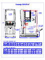
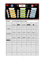
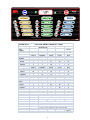
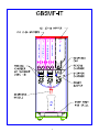
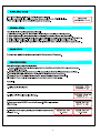
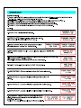
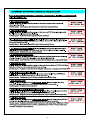
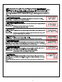
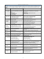
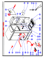
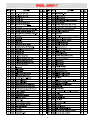
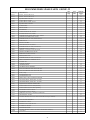
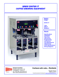
1
2
GB5-MF-IT
FACTORY GRAM THROW SETTINGS
FOR 8 OZ. CUP
FLAVOR
LATTES:
ORIGINAL
Fr. VANILLA
CARAMEL
CINNAMON
STEAMERS:
FROTHY MILK
Fr. VANILLA
CARAMEL
CINNAMIN
CAPPUCINO'S:
ORIGINAL
Fr.VANILLA
CARAMEL
CINNAMON
9/16/2005
COFFEE
MILK
VANILLA
5 grams
CARAMEL
4 grams
CINNAMON
5 grams
1.4 grams
20 grams
0
135
0
0
0
0
135
0
0
0
0
120
70
70
70
70
60
60
65
60
VANILLA
5 grams
CARAMEL
4 grams
CINNAMON
5 grams
COFFEE
0 grams
MILK
20 grams
0
110
0
0
0
0
135
0
0
0
0
110
0
0
0
0
55
55
55
55
VANILLA
5 grams
CARAMEL
4grams
CINNAMON
5 grams
COFFEE
2.2 grams
MILK
20 grams
0
135
0
0
0
0
135
0
0
0
0
120
140
140
140
140
60
60
65
65
ADJUSTMENT RANGE :
VANILLA
CARAMEL
CINNAMON
Use 23.0 pts. Of drink strength to increase 1 gram of product
COFFEE
Use 58.0 pts. Of drink strength to increase 1 gram of product
MILK
Use 2.15 pts. Of drink strength to increase 1 gram of product
Use 23.0 pts. Of drink strength to increase 1 gram of product
Use 18.25 pts. Of drink strength to increase 1 gram of product
NN90A-A
3
GB5-MF-HC-IT
FACTORY GRAM THROW SETTINGS
FOR 8 OZ. CUP
CAFÉ
STATION
12/2/2008
FLAVOR
ESPRESSO:
VANILLA
MOCHA
CINNAMON
ORIGINAL
CAPPUCCINO:
VANILLA
MOCHA
CINNAMON
ORIGINAL
COCOA:
VANILLA
MOCHA
CINNAMON
ORIGINAL
COFFEE
MILK
VANILLA
4 grams
CINNAMON
5 grams
COFFEE
3 grams
COCOA
20 grams
MILK
20 grams
135
0
0
0
0
0
135
0
170
170
170
185
0
100
0
0
60
60
60
60
VANILLA
4 grams
CINNAMON
5 grams
COFFEE
3 grams
COCOA
20 grams
MILK
20 grams
135
0
0
0
0
0
135
0
140
140
140
155
0
100
0
0
60
60
60
60
VANILLA
4 grams
CINNAMON
5 grams
COFFEE
2 grams
COCOA
40 grams
MILK
10 grams
135
0
0
0
0
0
125
0
0
100
0
0
125
125
125
150
30
30
30
10
ADJUSTMENT RANGE :
VANILLA
CINNAMON
Use 23.0 pts. Of drink strength to increase 1 gram of product
COFFEE
Use 58.0 pts. Of drink strength to increase 1 gram of product
COCOA
Use 2.0 pts. Of drink strength to increase 1 gram of product
MILK
Use 2.15 pts. Of drink strength to increase 1 gram of product
Use 18.25 pts. Of drink strength to increase 1 gram of product
NR58A-B
4
5
6
UNPACKING INSTRUCTIONS
Carefully unpack the GB Machine and inspect immediately for shipping damage. Your GB Machine was shipped in a carton
designed to give it maximum protection in normal handling. It was thoroughly inspected before leaving the factory. In case of
damage, contact the shipper, not Cecilware.
INSTALLATION INSTRUCTIONS
Water Inlet Connection:
This equipment is to be installed to comply with the applicable Federal, State, or local plumbing codes having jurisdiction. In
addition:
1. A quick disconnect water connection or enough extra coiled tubing (at least 2x the depth of the unit) so that the machine
can be moved for cleaning underneath.
2. An approved back flow prevention device, such as a double check valve to be installed between the machine and the
water supply.
The GB beverage dispenser is equipped with a 3/4" Garden Hose Connector which is located on the back of the unit.
HIGHLY RECOMMENDED:
A WATER SHUT-OFF VALVE and A WATER FILTER, preferably a combination Charcoal/ Phosphate Filter, to remove odors
and inhibit lime and scale build up in the machine.
Note: In areas with extremely hard water, a water softener must be installed in order to prevent a malfunctioning of the
equipment and in order not to void the warranty.
After the machine has been unpacked and placed on a counter, pull out the drip tray. It should contain the following:
A Set of 4 Adjustable Leveling Legs and a ¼” Flare Water Inlet Fitting.
START-UP PROCEDURE
1.
Connect the ¼" dia. copper waterline to the ¼" flare water inlet fitting of the valve.
2.
Plug the power cord into a proper receptacle.
3.
Activate the Power Switch (Toggle Up) located on the right side of the splash panel behind the door.
The power switch controls all power to the machine including the heater elements.
The door display panel will light up and the tank will start filling.
The LCD window will display this message briefly “CECILWARE, DISPENSER V#.## “.
4. The LCD window will display this message “Low Water Level”. Allow approximately 3 to 5 minutes for the tank to fill.
If the tank does not fill up within the first 5 minutes an error message will appear in the LCD window [SYSTEM ERROR, FILL
RESPONSE].
See Definition of Screen and Troubleshooting Guide.
5.
The LCD window will display this message “Low Water Temp.” Allow up to 30 minutes for the water to reach a temperature of
190°F.
The heat up time will depend on the water inlet temperature, the input voltage and the wattage of the elements in the machine.
While the tank is heating up, remove the hoppers, load them with products and reposition them back in the machine. Be sure to
reposition the hoppers so that the 1/4” pin slides into the hole of the compartment base.
When the machine has reached the proper dispensing temperature, the LCD window will display, “Press & Release to Dispense”
and “Please select choice of Drink”.
7
WATER LEVEL CONTROLS:
Under normal conditions and operation, the water level in the tank should not drop more than ½" from the probe.
If it does, the tank is not refilling fast enough. Check the water line and water filter, they may need cleaning or replacing.
Water Inlet Valve L462A
Water Level Probe K402Q [K402A & P410A]
ADJUSTMENTS
The Dispense Valves are factory adjusted for a proper Flow Rates.
[Approximate settings: 0.75 oz./sec for MILK; 0.375 oz./sec. for COFFEE and FLAVORS]
Exceeding this Flow Rate will cause the Mixing Chamber to overflow.
Note: To access the Water Dispense Valves, open door and remove Hoppers.
TO ADJUST WATER FLOW RATE:
1. Open door and remove hoppers. Locate Dispense Valve behind hoppers, mounted on tank.
2. Locate adjustment screw on Dispense Valve.
3. Using a 3 16" Allen Key or flat screwdriver rotate, 1/4 turn at a time,
CLOCKWISE to decrease water flow, or
COUNTERCLOCKWISE to increase water flow.
WATER FLOW ADJUSTMENT
4. Check water flow output, after each 1/4 turn.
8
PROGRAMMING INSTRUCTIONS
To access SERVICE MODE – Press simultaneously
Center of CECILWARE LOGO
and
Center of FAST FLOW LOGO
To access PROGRAM MODE – Press simultaneously
RINSE
and
STOP
To decrease or increase parameter
LCD WINDOW
TECHNOLOGY INSIDE
LCD WINDOW
CLEAR
PUSH
PUSH
PUSH
PUSH
PUSH
PUSH
PUSH
PUSH
PUSH
PUSH
PUSH
PUSH
MODES OF OPERATION
Initializing Mode – This mode is only active during the first few seconds after a “power-on” or system reset. The main
function of this mode is to configure the system using the previously saved operating parameters.
2. Normal Mode – This mode becomes active immediately after Initializing Mode has completed its tasks. The main
functions of this mode are to monitor and report system status and control dispensing.
3. Rinse Mode – This mode becomes active when the Rinse key is depressed with any dispense key. The main function of
this mode is to allow the operator to initiate an individual Rinse for all mixing chambers.
4. Program Mode – This mode becomes active when the Rinse and the Stop keys are simultaneously depressed for more
than 1.5 seconds while in Normal Mode. The main function of this mode is to provide limited access to frequently used
system parameters. Pressing the Rinse and the Stop keys again will return the touchpad to normal mode.
5. Service Mode – This mode becomes active when the hidden keys under the “Cecilware Logo” and the “Fast Flow
Logo” are simultaneously depressed for more than 1.5 seconds while in Normal Mode. The main function of this mode is
to allow access to all system parameters that can be modified. Pressing the “Cecilware Logo” and the “Fast Flow Logo”
again will return the touchpad to normal mode.
1.
9
Features and Benefits of the Digital Dispenser Controller
1. 100% Solid State Control for improved reliability
2. Modular design and reduced component count for ease of service
3. Optional sanitary features such as Rinse Lockouts and Rinse Warnings
4. Redundant system interlocks for uncompromising user safety
5. Large two line display for viewing system status and modifying parameters
6. Individual dispense counters and totalizers for product marketing information and inventory control
7. Advanced system diagnostics that continuously monitor the status of all motors, solenoids, sensors,
and heaters
to ensure proper operation and aid in identifying potential problems
8. Protection from heater burnout due to lack of water in the reservoir tank
9. Elimination of dry powder feed at the beginning of a dispense and product dilution at the end of a
dispense
10. Extremely accurate dispensing control utilizing DC servo-motor drive technology
11. Stable water temperature regulation with an adjustment resolution of one-degree Fahrenheit
12. Optional Low Water Temperature Lockout to prevent dispensing at water temperatures below an
adjustable threshold
13. Units of measure displayed in either English or Metric
14. Digital adjustment of serving sizes with a resolution of one-tenth of an ounce
15. Digital adjustment of gram throw with a resolution of one-percent-of-maximum
16. Audible alarm
17. User selectable “Portion Control” or “Free Flow” dispense modes
18. Optional power saving “sleep mode” for extended periods of inactivity
19. Easy to use menu-driven dispensing and rinsing instructions
10
PARAMETER DEFINITIONS FOR SYSTEM SOFTWARE
1.
Dispense Total – This parameter indicates the total amount of water dispensed (in ounces or milliliters) for a mixing
chamber. The Dispense Total does not include Rinse Dispenses. The maximum Dispense Total value is 16,777,216
ounces; after which the value will begin again from zero. This parameter cannot be reset to zero. Default Values has no
effect on this parameter.
2.
Dispense Counter – This parameter indicates the total number of cups dispensed for a selected Serving Size. The
Dispense Counter does not include Rinse Dispenses. The maximum Dispense Counter value is 49,999; after which the
value will begin again from zero. In Service Mode this parameter can be reset to zero by simultaneously depressing the
▼and ▲Keys. Default Values has no effect on this parameter.
3.
Dispense Mode – This parameter determines whether the system dispenses in a continuous (Free Flow) or fixed size
(Portion Control) method. The default setting for this parameter is Portion Control.
4.
Serving Size – This parameter determines the amount of water dispensed for each Dispense Key when the Dispense
Mode is set to Portion Control. The default setting is 8.0 ounces. The minimum Serving Size is 2.0 ounces. The
maximum Serving Size is 64.0 ounces.
5.
Gram Throw – This parameter determines the ratio of product to water during a Dispense for a selected Hopper. The
units of measure for Gram Throw are proportional to Auger Turns per ounce of water. At a Fill Constant of 1.00 ounces
per second the maximum Gram Throw is 100 and the minimum Gram Throw is 20. The maximum and minimum values
are scaled proportional to a Fill Constant of 1.00 ounces per second. For example: if the Fill Constant is set to 1.30
ounces per second the maximum Gram Throw would be (100*1.00)/1.3 = 77. This prevents the user from requesting a
Gram Throw that is beyond the capability of the Auger Motor. Auger Start and Stop Times have no effect on this
parameter. The default setting for this parameter will reset all gram throw settings to factory specs.
6.
Auger Start Time – This parameter sets the time that the Auger starts to turn relative to the activation (opening) of the
Dump Valve. A positive value indicates an Auger starting at some time after the opening of the Dump Valve. A negative
number indicates an Auger starting at some time before the opening of the Dump Valve. The minimum Auger Start Time =
(-3.0) seconds. The maximum Auger Start Time is 3.0 seconds. The default value for this parameter is 0.3 seconds.
7.
Mixer Start Time – This parameter sets the time that the Mixer starts to turn relative to the activation (opening) of the
Dump Valve. A positive value indicates a Mixer starting at some time after the opening of the Dump Valve. A negative
number indicates a Mixer starting at some time before the opening of the Dump Valve. The minimum Mixer Start Time = (3.0) seconds. The maximum Mixer Start Time is 3.0 seconds. The default value for this parameter is 0.3 seconds.
8.
Auger Stop Time – This parameter sets the time that the Auger stops turning relative to the de-activation (closing) of the
Dump Valve. A positive value indicates an Auger stopping at some time after the closing of the Dump Valve. A negative
number indicates an Auger stopping at some time before the closing of the Dump Valve. The minimum Auger Stop Time =
(-3.0) seconds. The maximum Auger Stop Time is 3.0 seconds. The default value for this parameter is 0.3 seconds.
9.
Mixer Stop Time – This parameter sets the time that the Mixer stops turning relative to the de-activation (closing) of the
Dump Valve. A positive value indicates a Mixer stopping at some time after the closing of the Dump Valve. A negative
number indicates a Mixer stopping at some time before the closing of the Dump Valve. The minimum Mixer Stop Time = (3.0) seconds. The maximum Mixer Stop Time is 3.0 seconds. The default value for this parameter is 0.6 seconds.
10. Fill Constant – This parameter must be set for each of the Dump Valves. The maximum Fill Constant is 1.5 oz/sec. The
minimum Fill Constant is 0.1 oz/sec. The maximum and minimum values are scaled proportional to a Gram Throw of 100.
For example: if the highest Gram Throw setting is 77 then the maximum Fill Constant would be (100*1.00)/77 = 1.30. This
prevents the user from requesting a Gram Throw that is beyond the capability of the Auger Motor. The default settings
for this parameter are 0.25 ounces per second for LEFT & MIDDLE CHAMBER, and 1.00 oz/sec For RIGHT (Milk)
CHAMBER.
11. Rinse Dispense Time – This parameter determines the amount of time that the Dump Valve is open during a Rinse
Cycle. The minimum Rinse Time = 3 seconds. The maximum Rinse Time is 15 seconds. The default value for this
parameter is 6 seconds.
11
12. Rinse Warning Status – This parameter determines whether the Rinse Warning Option is turned ON or OFF. If this
option is ON the system generates a Rinse Warning if a Hopper has dispensed and has not been rinsed for a period of
time greater than that defined by the Rinse Warning Time. Generating a Rinse Warning will cause the audible alarm to
sound for two seconds and the Rinse Warning Screen to be displayed for five seconds. The system will then revert back
to normal operation. If the offending Hopper is not rinsed after the first Rinse warning additional Rinse Warnings will be
generated every five minutes until the respective Hopper is rinsed. The default setting for this parameter is OFF.
13. Rinse Lockout Status - This parameter determines whether the Rinse Lockout Option is turned ON or OFF. If this option
is ON the system generates a Rinse Lockout if a Hopper has dispensed and has not been Rinsed for a period of time
greater than that defined by the Rinse Lockout Time. Once a Hopper enters Rinse Lockout the LED’s of the Dispense
Keys related to that Hopper will turn OFF thus indicating that the Hopper will no longer dispense. The default setting for
this parameter is OFF.
14. Rinse Lockout Time – This parameter determines the length of time required before entering Rinse Lockout. The
minimum Rinse Lockout Time = 1 hour. The maximum Rinse Lockout Time is 12 hours. The default value for this
parameter is 4 hours.
15. Water Temperature Set Point – This parameter determines the required reservoir tank water temperature. The minimum
Water Temperature Set Point is 140°F. The maximum Water Temperature Set point is 203°F. The default value for this
parameter is 190°F.
16. Low Water Temperature Lockout Status – This parameter determines whether the Low Water Temperature Lockout
Option is turned ON or OFF. If this option is ON the system generates a Low Water Temperature Lockout if the present
water temperature is below the value defined by the Low Water Temperature Lockout Set Point. Once a Hopper enters
Low Water Temperature Lockout, all of the Dispense Key LED’s will turn OFF thus indicating that the system will no longer
dispense. The default setting for this parameter is OFF.
17. Low Water Temperature Lockout Set Point – This parameter determines the minimum reservoir tank water temperature
allowed before entering Low Water Temperature Lockout. The minimum Low Water Temperature Lockout Set Point is
125°F. The maximum Low Water Temperature Lockout Set point is 203°F. The default value for this parameter is
140°F.
18. Water Level Actual – This parameter provides a readout of the water hardness level in the tank. Once provided, the water
level Setpoint can be adjusted so that the system will recognize the absence or presence of water at the level probes, thus
controlling the water level.
19. Water Level Setpoint – This parameter indicates the numerical value that the “Water Level Actual” readout must be before
the system allows water to fill the tank and eventually make contact with the level probes. Note: the “Water Level Setpoint
must be a higher reading than the “Water Level Actual”. The default value for this parameter is 400.
* If the “Water Level Actual” is higher than 400 then the Setpoint must be adjusted to a value 50 – 100 above the “Water
Level Actual” reading. This would be in a Hard Water condition.
* If the ”Water Level Actual is 300 or more below the default reading of 400, then the Setpoint must be adjusted to
50 – 100 above the “Water Level Actual” reading. This would be in a High Mineral content condition.
20. Sleep Mode Status – This parameter determines whether the Sleep Mode Option is turned ON or OFF. If this option is
ON and the system has not dispensed for four hours the system will enter Sleep Mode. Once in Sleep Mode the system
will reduce the required Water Temperature to equal that defined by (10°F + Low Water Temperature Lockout Set Point).
The default setting for this parameter is OFF.
21. Hopper Status – This parameter determines the whether a selected Hopper is turned ON or OFF. If a Hopper is ON then
the Auger Motor, Mixer Motor, and Dump Solenoid status checking is enabled and the Hopper is allowed to dispense. If a
Hopper is OFF then Auger Motor, Mixer Motor, and Dump Solenoid status checking is disabled and the LED’s of the
Dispense Keys related to that Hopper will turn OFF thus indicating that the Hopper will no longer dispense. The default
setting for this parameter is ON.
12
22. Blower Diagnostics – This parameter will monitor the status of the blower motor and display a warning if it senses a
problem. The default setting for this parameter is OFF.
23. Displayed Units – This parameter determines whether the displayed units of measure are English or Metric. If the
Displayed Units parameter is set to English then all temperatures are displayed as Degrees Fahrenheit and all volumes
are displayed as Fluid Ounces. If the Displayed Units parameter is set to Metric then all temperatures are displayed as
Degrees Celsius and all volumes are displayed as Milliliters. The default setting for this parameter is English.
24. Clock Settings – Need to set clock date (DAY, MONTH and YEAR) at the beginning life of the machine.
25. Default Values – Resets all parameters to FACTORY SETTINGS.
13
14
15
16
17
18
19
SANITIZING, CLEANING AND REFILLING HOPPERS
Sanitizing: All food dispensing units should be sanitized periodically. All parts to be sanitized must be cleaned first.
To prepare a sanitizing solution: ADD 2 TSP. OF LIQUID CLOROX BLEACH (5.25% CONCENTRATION) TO 1 GALLON
OF WATER AT ROOM TEMPERATURE (70°- 90°F).
Note: Always start with an unopened bottle of Clorox Bleach since the solution from an opened bottle has a short life
span.
• Soak all parts for a minimum of 3 min. in the sanitizing solution.
• Let all sanitized parts drain and dry naturally. DO NOT WIPE THEM DRY.
• Before using the sanitized unit (or parts) with food stuffs, rinse all parts thoroughly with water.
Water pipe connecting and fixtures directly connected to a potable water supply shall be sized, installed, and maintained in
accordance with Federal, Sate, and Local codes (section 7).
Cleaning
1. Turn the power switch to OFF.
2. Remove the drip tray with grill and empty the contents.
3. Wash and let dry the tray and grill (use a mild dishwasher detergent).
4. Wash and let dry the dispense area.
5. Turn the power switch to ON.
Cleaning the Hoppers
1. Open the cabinet door.
2. Take the hopper out of the cabinet.
3. Pull off the elbow chute and remove the hopper cover.
4. Unscrew the auger gear CW while holding steady the auger inside the hopper. Take out the auger, agitator
wheel, and spring.
5. Rinse each item thoroughly.
6. Let dry all items and reassemble.
Filling the Hoppers
1. Open the cabinet door.
2. Fill each hopper with the correct product.
3. Reposition hoppers in the hopper compartment, making sure the hoppers are properly seated.
Flushing the Whipper Chamber
1. Complete Rinse is initiated by simultaneously pressing Blue Rinse Button and any Drink Dispense Buttons.
Removing and Cleaning the Whipper Chambers (See Illustration)
1. Remove the dispense cap by pulling it forward and at the same time twisting it clockwise.
2. Grab and pull the mixing bowl out of the mixing bowl socket.
3. Grab and twist the whipping chamber clockwise and pull it off the mounting plate.
4. Pull the Whipper blade off the motor shaft. Notice the flat keyway on the shaft and the
matching keyway inside the Whipper blade shaft.
It is important that these two keyways are lined up when re-assembling the components.
5. Twist the mounting plate clockwise and pull it off the motor shaft.
6. Slip off the o-ring from the Whipper chamber mounting plate and clean o-ring and o-ring seat.
20
TROUBLE SHOOTING GUIDE
WARNING: To reduce the risk of electrical shock unplug the dispenser power cord before repairing or replacing any internal
components of the unit.. Before any attempt to replace a component be sure to check all electrical connections for proper
contact
PROBLEM
PROBABLE CAUSE
REMEDY
1. Light Display not a) Dispensing unit unplugged
lit. No power. b) No power from Main Board or from Power
Switch.
c) Defective Bulb
d) Loose Bulb in socket.
e) Defective Ballast.
2. No water when a) Water supply OFF.
Rinse Switch is b) Clogged inlet screen (Water Inlet Valve).
ON.
c) Inoperative Water Inlet Valve.
d) Loose electrical connection.
3. No product
a) No product in Hopper.
when Dispense b) Auger not working.
Button is
c) Damaged, loose, or missing Agitator Gear.
pressed
d) Inoperative Auger Motor.
e) Hopper outlet clogged
f) Faulty Coupling.
4. Water does not a) Leaking Solenoid [Water Inlet Valve].
shut off. Water b) Inoperative Switches on Touch Pad.
keeps
c) Inoperative Rinse Switch – Touch Pad
dispensing.
d) Clogged/stuck Water Dispense Valve
5. No water is
a) Water Inlet Valve malfunction.
going into tank
at all.
b) Probe malfunction.
6. Water will not a) Water Level Probe Malfunction.
stop flowing into b) Solenoid (Water Inlet Valve) Malfunction.
tank.
7. Water is not
a) Temperature setting is incorrect.
heating up in b) Loose connection to Heating element
the water tank. c) Heater is burned out or defective.
9. Water drips from a) Leaking Water Dispense Valve
mixing chamber b) Too much water in tank.
c) Mixing Chamber clogged.
d) Water Valve blocked by scales.
a) Reconnect dispensing unit
b) Check for loose wire to Main Board or to Power Switch.
c) Replace Bulb.
d) Make sure bulb is seated properly in socket.
e) Replace Ballast
a) Turn water ON.
b) Disconnect water line and clean inlet screen.
c) Check connection, if needed replace Valve.
d) Check all electrical connections.
a) Add product.
b) Engage Hopper/Nut to Motor Gear (see Ill. E).
c) Replace Agitator Gear (see Ill. E).
d) Check connections of Motor, if needed replace such components.
e) Clean Hopper and check Cartridge Heater.
f) Replace damaged Coupling components.
a) Clean/check fittings of Valve. Replace Valve if needed.
See ”Water Inlet Valve Test”
b) Check Touch Pad connections. Replace Touch Pad if needed.
d) Clean/unclog Water Dispense (Dump) Valve.
Replace Dispense Valve if inoperative.
a) Check Solenoid valve. Replace if necessary. See “Water Inlet
Valve Test”
b) Check Probe. Replace if necessary. See “Probe Test”.
a) Check Probe. Replace if necessary. See “Probe Test”
b) Check Solenoid. Replace if necessary. See “Water Inlet Valve
Test”
a) Set Temperature at 195°F – See Programming Instructions
b) Make sure all wires are tight.
c) Replace the Heater.
a) Replace Water Dispense (Dump) Valve
b) Dispense some water from tank.
c) Clean Mixing Chamber.
d) Replace or clean Valve seat.
10. Cold drink.
a) Run out of hot water
a) Allow time for water in tank to heat after filling.
b) Temperature setting is incorrect.
b) Set temperature at 195°F. (See Programming Instructions)
c) Loose electrical connection.
c) Check all electrical connections for contact.
d) Bad Heating Element or Heater is burned out. d) Replace Heater. (See Item 11 on Tank Assy. ILL. F).
11. Drink too
strong.
a) Water flow too low
b) Product throw too high
a) Adjust water flow rate (see Ill. B)
b) Adjust Gram Throw. (see Programming Instructions)
12. Drink too weak. a) No product in hopper
b) Product throw too low
c) Water flow too high
a) Add product
b) Adjust Gram Throw (see Programming Instructions)
c) Adjust water flow rate (see Ill. B)
13. Drink not
whipped.
a) Replace Whipper Blade
b) Check electrical connections to motor.
c) Replace Whipper Motor.
a) Whipper Blade missing.
b) Loose electrical connection to motor.
c) Whipper Motor defective.
21
14. Dispenser
repeats cycle
a) Touch Pad defective.
b) Power [Dispense] Relay stuck.
a) Replace Touch Pad.
b) Replace Relay.
15. Noise coming
from mixing
chamber
a) Whipper blade not properly aligned or
missing.
a) Check blade alignment, if needed replace blade and mixing
chamber.
16. Grinding noise a) Hopper not properly engaged in back, or
coming from
Hopper not seated properly
unit
a) Check the mating between the auger motor’s
gear and hopper’s coupling/nut. Check also pin in base.
Pin must be dropped into hole in base.
17. Banging or
clicking noise
coming from
hoppers
a) Fill Hoppers with product.
a) One or more Hoppers are empty or almost
empty.
22
23
24
25
26
27
28
29
30
RECOMMENDED SPARE PARTS GB5MF-IT
PART No.
DESCRIPTION
B138A
RELAY - 120VAC (SPDT 15A)
QTY
120V
1
B172A
B176A
B190A
RELAY - 240VAC (SPDT 15A)
SQUARE AXIAL FAN 120V
SAFETY RELAY 24 VDC
1
1
QTY
240V
MANUAL
PAGE #
25
1
25
25
25
B191A
SAFETY RELAY 24VDC D.P.S.T.
1
25
B202A
SQUARE AXIAL FAN 240V
1
25
B216A
LAMP HOLDER
1
1
25
CD110
IMPELLER DISC
2
2
24
CD124
SLINGER DISC
3
3
24
CD151
AUGER MOTOR 24V DC, 97 RPM
1
1
24
CD166
BLOWER MOTOR 240V, 50/60HZ
1
25
CD168
WHIPPER MOTOR, SHORT SHAFT 240V, 50/60HZ
2
24
CD169
WHIPPING CHAMBER (GRAY COLOR)
2
2
24
CD173
WHIPPER MOTOR, AC 120V (SHORT SHAFT)
1
CD61A
DISPENSE CAP
1
1
CD137
MIXING CHAMBER
1
1
24
CD341
GEAR MOTOR, 24V DC, 50 RPM
2
2
24
CD350
WHIPPER MOTOR, AC 120V (TWO FLATS)
1
CD353
WHIPPER BLADE W/ 2 FLATS
1
1
CD382
HOPPER, 1 3/4" W IDE W/ NYLON AUGER
2
2
24
CD385
MIXING CHAMBER (GRAY COLOR)
1
1
24
CD386
DISPENSE CAP (GRAY COLOR)
2
2
24
CD389
HOPPER, RIGHT 10 lbs
1
1
24
CD399
WHIPPER MOTOR, AC 240V (TWO FLATS)
CD409
DRIVE AUGER SHAFT 21MM FOR CD341
2
24
24
24
24
1
24
2
24
CD56A
BLOWER 120V
1
CD63A
WHIPPER CHAMBER
1
1
24
CD65A
CHAMBER MOUNT
CHAMBER MOUNT GROMMET
1
1
24
2
2
24
1
25
4
25
CD66A
CE80A
BULB, FLUORESCENT 18W TWIN TUBE 240V
CE82A
BULB, FLUORESCENT 18W TWIN TUBE 120V
1
CH246
FUSE (2 amp)
2
CH332
TRANSFORMER - 120V
1
CH474
TRANSFORMER - 240V
CH68A
DOOR CABLE (6 PIN) TO INTERFACE BOARD
1
G266A
HEATER ELEMENT, 3000W, 240W, 16" LONG
G267A
HEATER ELEMENT, 1700W, 120V, 16" LONG
1
K402Q
LIQUID LEVEL CONTROL SENSOR ASSY
1
1
25
25
25
1
25
1
25
1
23
1
23
23
L069A
TOGGLE SWITCH ON/OFF SPST [POWER]
L299A
TOGGLE SWITCH ON/OFF DPST [POWER]
L426A
WATER INLET VALVE 240VAC
L462A
1
25
L467A
WATER INLET VALVE 120VAC
DISPENSE VALVE 120 V, 7.5W 8mm (CLEAR SEAT)
1
23
L623A
HEATER TRIAC, 35 AMP
1
1
23
L627D
CONTROL BOARD, VER 8.10, (5 Chan. for units with Ser Nos up to N689056)
1
1
25
L641G
LEVEL SENSOR ASSEMBLY
1
1
25
L656A
HI-LIMIT 200° CUTOFF
1
1
23
1
23
1
1
25
L676A
DISPENSE VALVE 8mm 240 VAC
L736A
LCD DISPLAY BOARD
25
1
25
1
25
L742Q
THERMISTOR PROBE
1
1
23
L782D
NM43G
CONTROL BOARD, (CONSULT FACTORY FOR PROPER VERSION #)
TOUCHPAD
1
1
25
1
1
25
31
32
33
34
35