1
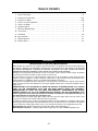
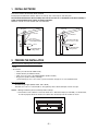
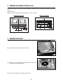
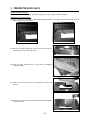
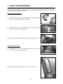
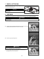
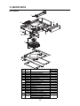
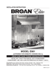
INSTALLATION INSTRUCTIONS
HB0040
MODEL E661
!
INTENDED FOR DOMESTIC COOKING ONLY
!
READ AND SAVE THESE INSTRUCTIONS
INSTALLER: LEAVE THIS MANUAL WITH HOMEOWNER.
HOMEOWNER: USE AND CARE INFORMATION ON PAGES 7 AND 8.
Broan-NuTone LLC; Hartford, Wisconsin www.broan.com 800-558-1711
Broan-NuTone Canada; Mississauga, Ontario www.broan.ca 877-896-1119
REGISTER YOUR PRODUCT ON LINE AT: www.broan.com/register
V06112 rev. I
!
WARNING
!
WARNING
TO REDUCE THE RISK OF FIRE, ELECTRIC
SHOCK OR INJURY TO PERSONS, OBSERVE
THE FOLLOWING:
TO REDUCE THE RISK OF INJURY TO PERSONS
IN THE EVENT OF A RANGE TOP GREASE
FIRE, OBSERVE THE FOLLOWING*:
1.
Use this unit only in the manner intended by the
manufacturer. If you have questions, contact the
manufacturer at the address or telephone number
listed in the warranty.
1.
2.
Before servicing or cleaning unit, switch power off
at service panel and lock service disconnecting
means to prevent power from being switched on
accidentally. When the service disconnecting
means cannot be locked, securely fasten a prominent
warning device, such as a tag, to the service panel.
SMOTHER FLAMES with a close-fitting lid,
cookie sheet or metal tray, then turn off the
burner. BE CAREFUL TO PREVENT BURNS. IF
THE FLAMES DO NOT GO OUT IMMEDIATELY,
EVACUATE AND CALL THE FIRE DEPARTMENT.
2.
NEVER PICK UP A FLAMING PAN – You may
be burned.
3.
DO NOT USE WATER, including wet dishcloths or
towels – This could cause a violent steam explosion.
4.
Use an extinguisher ONLY if:
A. You own a Class ABC extinguisher and
you know how to operate it.
B. The fire is small and contained in the area
where it started.
C. The fire department has been called.
D. You can fight the fire with your back to an exit.
3.
Installation work and electrical wiring must be done
by qualified personnel in accordance with all
applicable codes and standards, including fire-rated
construction codes and standards.
4.
Sufficient air is needed for proper combustion and
exhausting of gases through the flue (chimney) of
fuel burning equipment to prevent backdrafting.
Follow the heating equipment manufacturer’s
guidelines and safety standards such as those
published by the National Fire Protection
Association (NFPA), and the American Society for
Heating, Refrigeration and Air Conditioning
Engineers (ASHRAE), and the local code authorities.
* Based on “Kitchen Fire Safety Tips” published by NFPA.
CAUTION
5.
When cutting or drilling into wall or ceiling, do not
damage electrical wiring and other hidden utilities.
1.
6.
Ducted fans must always be vented to the
outdoors.
2.
7.
Do not use this unit with any additional solid-state
speed control device.
8.
To reduce the risk of fire, use only metal ductwork.
9.
This unit must be grounded.
10.
When the federal, provincial or state legislation
comprises more restrictive installation and/or
certification requirements, the aforementioned
requirements prevail on those of this document
and the installer agrees to conform to these at his
own expenses.
3.
4.
5.
6.
TO REDUCE THE RISK OF A RANGE TOP
GREASE FIRE:
a)
Never leave surface units unattended at high settings.
Boilovers cause smoking and greasy spillovers
that may ignite. Heat oils slowly on low or medium
settings.
b)
Always turn hood ON when cooking at high heat or
when flambeing food (i.e.: Crêpes Suzette,
Cherries Jubilee, Peppercorn Beef Flambé).
c)
Clean ventilating fans frequently. Grease should
not be allowed to accumulate on fan or filter.
d)
Use proper pan size. Always use cookware appropriate
for the size of the surface element.
7.
8.
9.
10.
-2-
For general ventilating use only. Do not use to
exhaust hazardous or explosive materials and vapors.
To avoid motor bearing damage and noisy and/or
unbalanced impeller, keep drywall spray,
construction dust, etc. off power unit.
Your hood motor has a thermal overload which will
automatically shut off the motor if it becomes
overheated. The motor will restart when it cools
down. If the motor continues to shut off and restart,
have the hood serviced.
The minimum hood distance above cooktop must
not be less than 24”. A maximum of 30” above
cooktop is highly recommended for best capture of
cooking impurities.
Two installers are recommended because of the
large size and weight of this hood.
To reduce the risk of fire and to properly exhaust
air, be sure to duct air outside – Do not exhaust air
into spaces within walls or ceiling or into attics,
crawl space or garage.
This product is equipped with a thermostat which
may start blower automatically. To reduce the risk
of injury and to prevent power from being switched
on accidentally, switch power off at service panel
and lock or tag service panel.
Because of the high exhausting capacity of this
hood, you should make sure enough air is entering
the house to replace exhausted air by opening a
window close to or in the kitchen.
Use with approved cord-connection kit only.
Please read specification label on product for
further information and requirements.
TABLE OF CONTENTS
1.
2.
3.
4.
5.
6.
7.
8.
9.
10.
11.
12.
INSTALL DUCTWORK . . . . . . . . . . . . . . . . . . . . . . . . . . . . . . . . . . . . . . . . . . . . . . . . . . . . . . . . . .4
PREPARE THE INSTALLATION . . . . . . . . . . . . . . . . . . . . . . . . . . . . . . . . . . . . . . . . . . . . . . . . . . . .4-5
PREPARE THE HOOD . . . . . . . . . . . . . . . . . . . . . . . . . . . . . . . . . . . . . . . . . . . . . . . . . . . . . . . .5-6
INSTALL THE ADAPTER/DAMPER . . . . . . . . . . . . . . . . . . . . . . . . . . . . . . . . . . . . . . . . . . . . . . . . . . .7
INSTALL THE HOOD . . . . . . . . . . . . . . . . . . . . . . . . . . . . . . . . . . . . . . . . . . . . . . . . . . . . . . . . . . .8
CONNECT WIRING . . . . . . . . . . . . . . . . . . . . . . . . . . . . . . . . . . . . . . . . . . . . . . . . . . . . . . . . . . . .8
REINSTALL BOTTOM PANEL . . . . . . . . . . . . . . . . . . . . . . . . . . . . . . . . . . . . . . . . . . . . . . . . . . . . .9
LIGHT BULBS . . . . . . . . . . . . . . . . . . . . . . . . . . . . . . . . . . . . . . . . . . . . . . . . . . . . . . . . . . . . . . .9
OPERATION . . . . . . . . . . . . . . . . . . . . . . . . . . . . . . . . . . . . . . . . . . . . . . . . . . . . . . . . . . . . . . .10
USE AND CARE . . . . . . . . . . . . . . . . . . . . . . . . . . . . . . . . . . . . . . . . . . . . . . . . . . . . . . . . . . . .11
WIRING DIAGRAM . . . . . . . . . . . . . . . . . . . . . . . . . . . . . . . . . . . . . . . . . . . . . . . . . . . . . . . . . . .11
SERVICE PARTS . . . . . . . . . . . . . . . . . . . . . . . . . . . . . . . . . . . . . . . . . . . . . . . . . . . . . . . . . . . .12
WARRANTY
BROAN-NUTONE LLC ONE-YEAR LIMITED WARRANTY
Broan-NuTone LLC warrants to the original consumer purchaser of its products that such products will be free
from defects in materials or workmanship for a period of one year from the date of original purchase. THERE ARE
NO OTHER WARRANTIES, EXPRESS OR IMPLIED, INCLUDING, BUT NOT LIMITED TO, IMPLIED
WARRANTIES OR MERCHANTABILITY OR FITNESS FOR A PARTICULAR PURPOSE.
During this one-year period, Broan-NuTone LLC will, at its option, repair or replace, without charge, any product
or part which is found to be defective under normal use and service.
This warranty does not cover (a) normal maintenance and service or (b) any products or parts which have been
subject to misuse, negligence, accident, improper maintenance or repair (other than by Broan-Nutone LLC),
faulty installation or installation contrary to recommended installation instructions.
The duration of any implied warranty is limited to the one-year period as specified for the express warranty. Some
states or provinces do not allow limitation on how long an implied warranty lasts, so the above limitation may not
apply to you.
BROAN-NUTONE LLC’S OBLIGATION TO REPAIR OR REPLACE, AT BROAN-NUTONE LLC’S OPTION,
SHALL BE THE PURCHASER’S SOLE AND EXCLUSIVE REMEDY UNDER THIS WARRANTY.
BROAN-NUTONE LLC SHALL NOT BE LIABLE FOR INCIDENTAL, CONSEQUENTIAL OR SPECIAL
DAMAGES ARISING OUT OF OR IN CONNECTION WITH PRODUCT USE OR PERFORMANCE. Some
states or provinces do not allow the exclusion or limitation of incidental or consequential damages, so
the above limitation or exclusion may not apply to you.
This warranty gives you specific legal rights, and you may also have other rights, which vary from state to state
or province to another. This warranty supersedes all prior warranties.
To qualify for warranty service, you must (a) notify Broan-NuTone LLC at the addresses or telephone number stated
below, (b) give the model number and part identification and (c) describe the nature of any defect in the product
or part. At the time of requesting warranty service, you must present evidence of the original purchase date.
Broan-NuTone LLC, 926 West State Street, Hartford, WI 53027 USA 1-800-558-1711
Broan-NuTone Canada Inc., 1140 Tristar Drive, Mississauga, ON L5T 1H9 CANADA 1-888-896-1119
-3-
1. INSTALL DUCTWORK
Plan where and how the ductwork will be installed.
Install proper-sized ductwork, elbows and roof or wall cap. Use 2” duct tape to seal duct joints.
The minimum hood distance above cooktop must not be less than 24”. A maximum of 30” above cooktop is
highly recommended for best capture of cooking impurities.
Distances over 30” are at the installer and users discretion.
Roof cap
Roof cap
3¼" x 10" duct
7" round duct
Wall
cap
Wall
cap
3¼" x 14" to
3¼" x 10" adaptor
model T461 (included)
Transition model 462
3¼" x 10" to 7" round
Hood
Hood
24" minimum above
cooking surface
24" minimum above
cooking surface
HH0109A
HH0110A
2. PREPARE THE INSTALLATION
Make sure that the following items are included:
- Hood
- Accessories:
• Filters (2 for 30’’ and 36’’ width hoods)
• Plastic diverter (assembled in hood)
• T461 3¼” x 14” to 3¼” x 10” adapter/damper (inside one filler)
• Bag of parts (inside one filler) including:
(1) wire clamp, (5) no. 8 x 1/2” screws, (2) wire connectors and (3) no. 6 x 1/2” standard screws
Parts sold separately:
-
Shielded halogen lights (MR16, GU10, 120 V, 50 W)
Transition 3¼” x 10” to 7” round model no. 412 (optional), ducts, elbows, dampers, wall or roof caps.
NOTES: 1. During installation, protect countertop and/or cooktop.
2. If the bottom of the cabinet is recessed, attach four 1’’ wide wood strips (not included), as shown below,
in order to properly attach the hood to the cabinet. The wood strips must be as thick as recess.
CABINET BOTTOM
1”
1”
1”
1¾’’
10¼’’
5¼’’
HO0028A
-4-
1”
1¾’’
2. PREPARE THE INSTALLATION (CONT’D)
Cut-out the openings for duct (A) and power cable (B), in cabinet or wall, according to the direction of discharge
chosen.
See figures below.
NOTE: The duct opening width (A on figures below) is 10½”, centered.
HORIZONTAL
VERTICAL
DISCHARGE
DISCHARGE
CABINET BOTTOM
C
L
1½’’
A
C
L
1³ 8’’
4¼’’
A
7¼’’
3½”
7 8”
7¼”
HD0121A
HD0120A
7¼”
7¼’’
B
2’’
2’’
7/8’’
B 2¾”
1½” dia.
3. PREPARE THE HOOD
3.1 Pull latch tabs and remove filters from the hood.
HD0107
SCREW
LOCATIONS
3.2 Remove the 5 screws retaining the bottom panel to the hood and
set aside. Pull out the bottom panel.
HO0030
3.3 Punch out the appropriate electrical knock-out hole.
-5-
3. PREPARE THE HOOD (CONT’D)
FOR VERTICAL DISCHARGE ONLY:
The hood is set up at the factory for vertical discharge. Go to step 4 on page 7. Start on step 4.4.
FOR HORIZONTAL DISCHARGE ONLY:
3.4 From inside the hood, unfold the small retaining tab (A) (located on the edge of the blower opening) on the air
diffuser edge. See pictures below.
A
A
HD0109
HD0108
Folded tab
Unfolded tab
3.5 Remove the metal shutoff plate from the back of the hood, by
removing the 3 screws. Set aside scews.
HO0031
3.6 Press the metal shutoff plate on a flat surface to completely
flatten bent flange.
HD0119
3.7 From the top of the hood, slide out the plastic air deviator and
discard.
HO0032
3.8 Using the 3 screws removed from 3.5, install the metal shutoff plate
on top of the hood.
HO0036
-6-
4. INSTALL THE ADAPTER/DAMPER
The wall duct must be roughed-in to properly interface with the hood. Before performing the installation, make sure the
adapter fits easily in the duct. If this hood replaces an existing hood, please note that location of the air exhaust can
vary from one hood manufacturer to another.
FOR HORIZONTAL DISCHARGE ONLY:
4.1 Fold down the foldable flange of the adapter/damper. This flange must be at
90° from the remaining flanges. See picture beside.
HD0112
4.2 Using three (3) no. 6 x 1/2’’ screws provided, secure the adapter to the back
of the hood. Remove tape from damper flap.
HO0037
4.3 Seal the adapter and the metal shutoff plate to the hood using duct tape.
HD0113
FOR VERTICAL DISCHARGE ONLY:
4.4 Using three (3) no. 6 x 1/2” screws provided, secure the adapter to the top
of the hood. Remove tape from damper flap.
HO0033
4.5 Seal the adapter and the metal plate to the hood using duct tape.
HO0038
-7-
5. INSTALL THE HOOD
5.1 Run power cable to installation location. Position the hood in its intended location. Using a pen, mark the position
of the screws (smaller part of the keyholes, see pictures below for the (5) keyholes locations). Remove the hood.
5.2 Install (4) no. 8 x 1/2’’ screws, leaving a 1⁄8’’ gap (do not install the no. 5 screw yet).
3
1
5
1
4
2
2
3
4
HD0122
HD0123
HD0115
5.3 Attach the wire clamp, insert the power cable in the hood and tighten the wire clamp to secure the cable. Place
the hood under the cabinet and slide it in position. Make sure the adapter/damper assembly enters the duct
opening. Tighten the (4) screws completely, then add the last screw (screw no. 5) in the center keyhole. Make sure
the damper flap opens freely.
6. CONNECT WIRING
! WARNING
Risk of electrical shock. Electrical wiring must be done by qualified personnel in accordance with
all applicable codes and standards. Before connecting wires, switch power off at service panel and
lock service disconnecting means to prevent power from being switched on accidentally.
Connect cable into wiring box using provided wire connectors.
Connect wires as follows: BLACK to BLACK, WHITE to WHITE and GREEN or
BARE wire under GREEN ground screw. DO NOT FORGET TO CONNECT THE
GROUND.
GROUND
SCREW
HD0123
-8-
7. REINSTALL BOTTOM PANEL
Reinstall the bottom panel, using 5 screws saved from step 3,
as shown beside. Reinstall filters.
CAUTION
Remove protective plastic film covering filters before
installing them.
HD0124
8. LIGHT BULBS
This hood must use 120 V, 50 W max., type MR16, GU10 shielded halogen lamps. (Purchase separately).
! WARNING
In order to prevent the risk of personal injury, do not install a lamp identified for use only in
enclosed fixtures.
NOTE: The rings must be removed from bottom banel before installing halogen lamps.
8.1 Install the lamps by placing the bulb leads into their grooves in the socket
and gently push upward and turn clockwise until secured.
HE0047
8.2 Install trim rings by pushing upward.
HO0034
! WARNING
In order to prevent the risk of personal injury, the halogen lamps
must be cooled down before removing them.
8.3 To remove lamps, gently push upward and turn counterclockwise to
disengage bulb leads from their grooves.
HE0047
-9-
9. OPERATION
Always turn your blower on before you begin cooking to establish an air flow in the kitchen. Let the blower run for a few
minutes to clear the air after you turn off the range.
HC0016
A
B
C
A) Blower Delay switch
B) ON blower / Speed control switch
C) OFF blower / Filter maintenance switch
D
E
D) OFF lighting
E) Halogen light switch
A. BLOWER DELAY SWITCH:
When a speed is selected, press the delay switch to activate the delay function. The corresponding speed indicator LED
will start flashing to indicate this function is activated. The fan will continue to operate for 5 minutes and will stop
automatically. To cancel the delay function, press the blower delay switch once again; the blower will then work in
normal mode.
NOTE: The blower speed can be increased—or decreased—during delay mode without starting another 5-minute cycle.
B. ON BLOWER / SPEED CONTROL SWITCH:
Press this switch to turn on the blower at the last selected speed. To change the blower speed, press the switch again
until the desired speed is obtained.
NOTES: 1. Each time you press the speed control switch, the speed changes by increments of 1 (e.g.: speed 1
to speed 2, to speed 3, and then speed 4.) From the fourth speed, the speed goes down to level 1.
2. The last speed used is kept in memory so that when the unit is turned on, it will return to the last setting
except the fourth, the next time the blower will be turned on, it will return to speed 3.
HEAT SENTRY™
This hood is equipped with a Heat Sentry thermostat. This thermostat is a device that will turn on or speed up the blower
if it senses excessive heat above the cooking surface.
1) If blower is OFF—it turns blower ON to speed 3.
2) If blower is ON at a lower speed setting—it turns the blower up to speed 3. If blower is at Boost, HEAT SENTRY™
turns blower down to speed 3.
When HEAT SENTRY™ is activated, the first and the last speed blower LEDs are flashing alternately.
When the temperature level drops to normal, the blower will return to its original setting.
! WARNING
The HEAT SENTRY™ can start the blower even if the hood is turned OFF. In this case, it is impossible to
turn the blower OFF with blower switch. To prevent the blower from starting, turn off power at the
main electrical panel.
C. OFF BLOWER / FILTER MAINTENANCE SWITCH:
Press this switch to turn off the blower. Pressing this switch also cancels the delay function (if activated).
NOTE: After 25 hours of operation, all blower LEDs will flash during 30 seconds to indicate the filters need to be
cleaned in order to maintain efficient hood operation. The LEDS will continue to flash until the function is reset
by pressing on this switch for 3 seconds.
D. OFF LIGHTING:
Press this switch to turn off lighting.
E. HALOGEN LIGHT SWITCH:
Press this switch to turn on the halogen lamps. The lighting intensity changes by increments of 1 (e.g.: Press once for low
intensity, once again to get more, up to three times.) From the higher intensity, press once to go back to the lower intensity.
NOTE: The last lighting intensity used is kept in memory. The next time the halogen lamps will be turned on, they will
light with the last intensity used.
RESET CONTROL PROCEDURE:
If ever the control locks up, turn off power at the main electrical panel for 5 seconds. Then, turn on power at the main
electrical panel. The control will be reset.
- 10 -
10. USE AND CARE
Grease filters and bottom panel.
The grease filters and the bottom panel should be cleaned frequently. Use a warm detergent solution.
Remove grease filters by pushing them towards the back of hood and rotating downward.
Clean all-metal filters in the diswasher using a non-phophate detergent. Discoloration of the filter may occur if using
phosphate detergents, or as a result of local water conditions — but this will not affect filter performance. This discoloration
is not covered by the warranty.
STAINLESS
STEEL CLEANING:
HOW TO
MAINTAIN ITS
« BRIGHT LOOK »
Do: - Regularly wash surfaces with clean cloth or rag soaked with warm water and mild soap or liquid dish detergent.
- Always clean in the direction of original polish lines.
- Always rinse well with clear water (2 or 3 times) after cleaning. Wipe completely dry.
- You may also use a specialized household stainless steel cleaner.
Don’t: - Do not use any steel or stainless steel wool or any other scrapers to remove stubborn dirt.
- Do not use any harsh or abrasive cleansers.
- Do not allow dirt to accumulate.
- Do not let plaster dust or any construction residues reach the hood. During construction or renovation, cover
the hood to make sure no dust adheres to stainless steel surface.
Avoid: when choosing a detergent
- Any cleaners that contain bleach will attack stainless steel.
- Any products containing : chloride, fluoride, iodide, bromide will deteriorate surfaces rapidly.
- Any combustible products used for cleaning such as acetone, alcohol, ether, benzol, etc., are highly explosive
and should never be used close to a range.
ENAMEL FINISH:
Clean with warm water and mild detergent only. If discoloration occurs, use a good enamel polish such as automotive
polish. (DO NOT use rough abrasive cleaner or porcelain cleaner).
11. WIRING DIAGRAM
! WARNING
Risk of electrical shock. Electrical wiring must be done by qualified personnel in accordance with
all applicable codes and standards. Before connecting wires, switch power off at service panel and
lock service disconnecting means to prevent power from being switched on accidentally.
Line 120 V
Supply BK
Neutral
W
Ground
W
Light Socket
W 50 W max.
Y
W
Y
W Light Socket
50 W max.
BN
BL
BK
FAN MOTOR
J5
BK 3
2 nc
W 1
BK
W
J6
Y 3
2
BK
nc 1
BK
G
nc
BK
W
W
nc Y [120]
R [70]
P [50]
BL [35]
O [0]
nc
BK
R
P
BL
J4
4
3
2
1
A1
ELECTRONIC
ASSEMBLY
Main power board
J2
16
WIRING COLOR CODE
BK
BL
BN
G
O
BLACK
BLUE
BROWN
GREEN
ORANGE
P
R
W
Y
nc
PURPLE
RED
WHITE
YELLOW
no connection
A2
ELECTRONIC
ASSEMBLY
User Interface
-t°
Heat Sentry
NOTES
1. If any of the original wire, as supplied, must be replaced, use the
same equivalent wire.
2. Field wiring must comply with applicable codes, ordinances and
regulations.
HE0042A
- 11 -
12. SERVICE PARTS
E661 MODEL
1
11
2
13
3
9
8
12
10
4
5
6
6
7
HL0052
KEY
NO.
1
2
3
4
5
6
*
PART
NO.
T461
V06118
V05917
V06735
V01766E
V06268
V06244
V06264
V02160
V06750
V06733-1
V06252
V05921
V03443
V06734
V06745
V06112
*
V06751
7
8
9
10
11
12
13
*
DESCRIPTION
ADAPTER/DAMPER
ELECTRONIC CONTROL
LAMP SOCKET
TRANSFORMER AND HARNESS KIT
MOTOR (INCLUDING WHEEL)
LIGHT TRIM RING
FILTERS 9.92” x 17.981”
FILTERS 12.922” x 17.981”
CAPACITOR
BROAN ELITE LOGO
CONTROL PROCESSOR UNIT
DIVERTER
HALOGEN LAMP (50 W, 120 V, GU10)
FOAM STRIP
LOW VOLTAGE HARNESS
LOW VOLTAGE HARNESS
INSTALLATION MANUAL
PARTS BAG (1) wire clamp LP16-AP,
(2) wire connectors no. 74B, (5) no. 8 x 1/2”
screws, (3) no. 6 x 1/2” screws)
* Item not shown.
- 12 -
WIDTHS
30”
36”
1
1
1
1
2
2
1
1
1
1
2
2
2
2
1
1
1
1
1
1
1
1
2
2
1
1
1
1
1
1
1
1