1
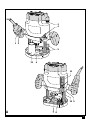
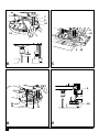
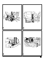
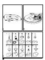
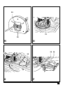
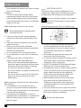
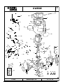
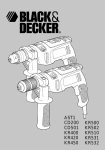
KW850E
1
Copyright Black & Decker
2
3
4
1 2
5
12
6
11
10 9
A
7 8
3
7
6
13
5
15
14
5
15
3 mm
B
C
9
X
12
16
D
4
18
17
E
11
9
9
10
18
10
F
G
19
H
I
5
K
J
L
6
1
2
3
4
5
6
7
8
9
10
20
21
16
M
N
25 24
23
22
O
P
7
ENGLISH
ROUTER KW850E
CONGRATULATIONS!
You have chosen a Black & Decker tool. Our aim is
to provide quality tools at an affordable price.
We hope that you will enjoy using this tool for
many years.
INTENDED USE
Your Black & Decker router KW850E has been
designed for routing wood and wood products.
This tool is intended for consumer use only.
SAFETY INSTRUCTIONS
EC DECLARATION OF CONFORMITY
Warning symbols
The following symbols are used in this manual:
KW850E
Black & Decker declares that these
products conform to:
98/37/EC, 89/336/EEC, 73/23/EEC,
EN 50144, EN 55014, EN 61000
Denotes risk of personal injury, loss of life
or damage to the tool in case of nonobservance of the instructions in this
manual.
Level of sound pressure, measured according to
EN 50144:
Denotes risk of electric shock.
KW850E
(sound pressure)
dB(A)
85.5
LWA (acoustic power)
dB(A)
98.5
LpA
Always wear ear protection if the sound
pressure exceeds 85 dB(A).
Read the manual prior to operation.
Know your tool
◆
Hand/arm weighted vibration value according to
EN 50144:
KW850E
< 2.5 m/s2
◆
◆
◆
Kevin Hewitt
Director of Consumer Engineering
Spennymoor, County Durham DL16 6JG,
United Kingdom
8
Warning! When using mains-powered
tools, basic safety precautions,
including the following, should always
be followed to reduce the risk of fire,
electric shock, personal injury and
material damage.
Read all of this manual carefully before
operating the tool.
Before operating the tool, make sure
that you know how to switch the tool off
in an emergency.
Retain this manual for future reference.
ENGLISH
General
1. Keep work area clean
Cluttered areas and benches can cause accidents.
2. Consider work area environment
Do not expose the tool to rain. Do not use the
tool in damp or wet conditions. Keep the work
area well lit. Do not use the tool where there is
a risk of causing fire or explosion, e.g. in the
presence of flammable liquids and gases.
3. Keep children away
Do not allow children, visitors or animals to
come near the work area or to touch the tool
or mains cable.
4. Dress properly
Do not wear loose clothing or jewellery, as these
can be caught in moving parts. Preferably wear
rubber gloves and non-slip footwear when
working outdoors. Wear protective hair
covering to keep long hair out of the way.
5. Personal protection
Always use safety glasses. Use a face or dust
mask whenever the operations may produce
dust or flying particles. Wear ear protection
whenever the sound level seems uncomfortable.
6. Guard against electric shock
Prevent body contact with earthed or
grounded surfaces (e.g. pipes, radiators,
cookers and refrigerators). Electric safety can
be further improved by using a high-sensitivity
(30 mA / 30 mS) residual current device (RCD).
7. Do not overreach
Keep proper footing and balance at all times.
8. Stay alert
Watch what you are doing. Use common sense.
Do not operate the tool when you are tired.
9. Secure workpiece
Use clamps or a vice to hold the workpiece.
It is safer and it frees both hands to operate
the tool.
10. Connect dust extraction equipment
If devices are provided for the connection of
dust extraction and collection facilities, ensure
that these are connected and properly used.
11. Remove adjusting keys and wrenches
Always check that adjusting keys and wrenches
are removed from the tool before operating
the tool.
12. Extension cables
Before use, inspect the extension cable and
replace if damaged. When using the tool
outdoors, only use extension cables intended
for outdoor use.
13. Use appropriate tool
The intended use is described in this
instruction manual. Do not force small tools or
attachments to do the job of a heavy-duty tool.
The tool will do the job better and safer at the
rate for which it was intended. Do not force the
tool.
Warning! The use of any accessory or attachment
or performance of any operation with this tool
other than those recommended in this instruction
manual may present a risk of personal injury.
14. Check for damaged parts
Before use, carefully check the tool and mains
cable for damage. Check for misalignment and
seizure of moving parts, breakage of parts,
damage to guards and switches and any other
conditions that may affect its operation.
Ensure that the tool will operate properly and
perform its intended function. Do not use the
tool if any part is damaged or defective.
Do not use the tool if the switch does not turn
it on and off. Have any damaged or defective
parts repaired or replaced by an authorised
repair agent. Never attempt any repairs yourself.
15. Unplug the tool
Unplug the tool when it is not in use, before
changing any parts of the tool, accessories or
attachments and before servicing.
16. Avoid unintentional starting
Do not carry the tool with a finger on the on/
off switch. Be sure that the tool is switched off
when plugging in.
17. Do not abuse cord
Never carry the tool by its cord or pull it to
disconnect from the socket. Keep the cord
away from heat, oil and sharp edges.
18. Store idle tools
When not in use, tools should be stored in a dry,
locked up or high place, out of reach of children.
19. Maintain tools with care
Keep cutting tools sharp and clean for better
and safer performance. Follow the instructions
for maintenance and changing accessories.
9
ENGLISH
Keep handles and switches dry, clean and free
from oil and grease.
20. Repairs
This tool complies with relevant safety
requirements. Repairs should only be carried
out by qualified persons using original spare
parts; otherwise this may result in considerable
danger to the user.
ELECTRICAL SAFETY
The electric motor has been designed for one
voltage only. Always check that the power supply
corresponds to the voltage on the rating plate.
Additional safety instructions for routers
Mains plug replacement (U.K. & Ireland only)
This tool is double insulated in accordance
with EN 50144; therefore no earth wire is
required.
Wear safety glasses or goggles when
operating this tool.
◆
◆
◆
◆
◆
◆
Only use router bits with a shank diameter
equal to the size of the collet installed in the
tool.
Only use router bits suitable for the no-load
speed of the tool.
Never use router bits with a diameter
exceeding the maximum diameter specified in
the technical data section.
Do not use the tool in an inverted position.
Do not attempt to use the tool in a stationary
mode.
Take special care when routing MDF or
surfaces coated with lead-based paint:
- Wear a dust mask specifically designed for
protection against lead paint dust and fumes
and ensure that persons within or entering
the work area are also protected.
- Do not let children or pregnant women enter
the work area.
- Do not eat, drink or smoke in the work area.
- Dispose of dust particles and any other
debris safely.
Additional safety instructions for Australia and
New Zealand
◆ This appliance is not intended for use by
young or infirm persons without supervision.
Children must be supervised to ensure they do
not play with the appliance.
◆ If the supply cord is damaged, it must be
replaced by the manufacturer or an authorised
Black & Decker Service Centre in order to
avoid a hazard.
10
◆
◆
◆
◆
◆
◆
◆
Should your mains plug need replacing and
you are competent to do this, proceed as
instructed below. If you are in doubt, contact
an authorised repair agent or a qualified
electrician.
Disconnect the plug from the supply and
remove the fuse from the plug.
Cut off the plug and dispose of it safely; a plug
with bared copper conductors is dangerous if
engaged in a live socket outlet.
Only fit 13 Amperes BS1363A approved plugs
fitted with the correctly rated fuse (1).
The cable wire colours, or a letter, will be marked
at the connection points of most good quality
plugs. Attach the wires to their respective
points in the plug (see above). Brown is for
Live (L) (2), blue is for Neutral (N) (4).
Before replacing the top cover of the mains
plug ensure that the cable restraint (3) is
holding the outer sheath of the cable firmly
and that the leads are correctly fixed at the
terminal screws.
If the plug has a fuse cover, make sure that the
fuse cover is fitted. Do not use the plug if the
fuse cover is missing or damaged.
Never use a light socket.
ENGLISH
Using an extension cable
Always use an approved extension cable suitable
for the power input of this tool (see technical
data). Before use, inspect the extension cable for
signs of damage, wear and ageing. Replace the
extension cable if damaged or defective.
When using a cable reel, always unwind the cable
completely. Use of an extension cable not suitable
for the power input of the tool or which is damaged
or defective may result in a risk of fire and electric
shock.
Fitting a router bit (fig. B)
◆ Keep the spindle lock (7) depressed and rotate
the spindle until the spindle lock fully engages.
◆ Loosen the collet nut (13) using the spanner
provided.
◆ Insert the shank of the router bit (14) into the
collet (6). Make sure that the shank protrudes
at least 3 mm from the collet as shown.
◆ Keep the spindle lock (7) depressed and
tighten the collet nut (13) using the spanner
provided.
PACKAGE CONTENTS
The package contains:
1 Router
3 Collets
1 Spanner
1 Edge guide
1 Dust extraction adaptor
1 Centring pin
1 Copy follower
1 Distance plate
1 Template guide
1 Instruction manual
Fitting the edge guide (fig. C)
The edge guide helps to guide the tool parallel to
an edge.
◆ Insert the bars (15) into the router base as shown.
◆ Set the edge guide to the required distance.
◆ Tighten the fixing screws (5).
◆
Carefully unpack all parts.
OVERVIEW (fig. A)
1. On/off switch
2. Lock-off button
3. Variable speed control knob
4. Plunge lock lever
5. Fixing screws for edge guide
6. Collet
7. Spindle lock button
8. Revolver depth stop
9. Depth stop bar
10. Locking screw
11. Depth of cut scale
12. Dust extraction adaptor
Fitting the dust extraction adaptor (fig. D)
The dust extraction adaptor allows you to connect
a vacuum cleaner to the tool.
◆ Place the dust extraction adaptor (12) onto the
base of the tool as shown.
◆ Insert the two screws (16) from the bottom
through the holes in the base and in the dust
extraction adaptor.
◆ Place a nut (17) onto each of the screws and
securely tighten the nuts.
Fitting the template guide (fig. M & D)
◆ Fit the template guide (20) to the base of the
router, with the flange to the bottom
(= workpiece) side.
◆ Insert the two long screws (16) from the
bottom side through the template guide and
the holes in the base.
◆ Place the dust extraction adaptor on top of the
base as shown in fig. D.
◆ Place a nut (17) onto each of the screws and
securely tighten the nuts.
ASSEMBLY
Before attempting any of the following
operations, make sure that the tool is
switched off and unplugged and that the
spindle has stopped.
Fitting the distance piece (fig. N)
◆ Fit the distance piece (21) to the base of the
router using the screws provided.
11
ENGLISH
Fitting the centring pin (fig. O)
◆ Fit the edge guide to the router as shown in
fig. C, but upside down.
◆ Fit the centring pin (22) to the workpiece side
of the edge guide with the screw (23) provided.
Fitting the copy follower (fig. P)
◆ Fit the edge guide to the router as shown in
fig. C.
◆ Fit the ‘L’ bar (24) to the upper side of the edge
guide using the two screws and nuts provided.
◆ Fit the rotating attachment (25) to the ‘L’ bar
with the wing screw provided.
USE
Let the tool work at its own pace.
Do not overload.
◆
Carefully guide the cable in order to avoid
accidentally cutting it.
Adjusting the depth of cut (fig. E)
The depth of cut is the distance X between the
depth stop bar (9) and the depth stop (18).
The depth of cut can be set in two different ways
as described below.
Adjusting the depth of cut using a piece of wood
(fig. A & F)
◆ Fit the router bit as described above.
◆ Loosen the locking screw (10).
◆ Pull the plunge lock lever (4) up.
◆ Plunge the router down until the router bit
touches the workpiece.
◆ Push the plunge lock lever (4) down.
◆ Pull the depth stop bar (9) up.
◆ Place a piece of wood with a thickness equal to
the desired depth of cut between the depth
stop (18) and the depth stop bar (9).
◆ Tighten the locking screw (10).
◆ Remove the piece of wood.
◆ Pull the plunge lock lever (4) up and let the
router return to its original position.
◆ After switching the router on, plunge it down
and make the desired cut.
12
Adjusting the depth of cut using the scale
(fig. A & G)
◆ Fit the router bit as described above.
◆ Loosen the locking screw (10).
◆ Pull the plunge lock lever (4) up.
◆ Plunge the router down until the router bit
touches the workpiece.
◆ Push the plunge lock lever (4) down.
◆ Read the starting position from the scale (11).
◆ Add the desired depth of cut to the starting
position.
◆ Move the depth stop bar (9) to the calculated
position on the scale.
◆ Tighten the locking screw (10).
◆ Pull the plunge lock lever (4) up and let the
router return to its original position.
◆ After switching the router on, plunge it down
and make the desired cut.
Adjusting the revolver depth stop (fig. H)
After turning the revolver depth stop to the desired
setting, you can fine-adjust the depth stop to be used.
If you want to make several cuts with a different
depth of cut, adjust each of the depth stops.
◆ Turn the depth stop screw (19) up or down as
required using a screwdriver.
Setting the speed (fig. A)
◆ Set the speed control knob (3) to the required
speed. Use a high speed for small diameter
router bits. Use a low speed for large diameter
router bits.
Using a batten as a guide (fig. I)
When it is not possible to use the edge guide,
for example when routing grooves in the back
panel of a bookcase to support shelves,
proceed as follows:
◆ Place a batten onto the workpiece.
◆ Move the batten until it is in the correct
position to guide the tool.
◆ Securely clamp the batten to the workpiece.
Using the template guide (fig. M)
The template guide can be used to make a cutout
shape from a template, for instance a letter.
◆ Secure the template over the workpiece with
double-sided tape or ‘G’ clamps.
ENGLISH
◆
The router bit must extend below the flange of
the template guide, to cut the workpiece in the
shape of the template.
◆
Refer to the table below for common types of
router bits.
Router bits (fig. L)
Using the distance piece (fig. N)
The distance piece can be used for trimming
wooden or laminate vertical projections.
Using the centring pin (fig. O)
The centring pin can be used to cut out circular
patterns.
◆ Drill a hole for the point of the centring pin in
the centre of the circle to be cut.
◆ Place the router on the workpiece with the
point of the centring pin in the drilled hole.
◆ Adjust the radius of the circle with the bars of
the edge guide.
◆ The router can now be moved over the
workpiece to cut out the circle.
Using the copy follower (fig. P)
The copy follower helps to maintain an equal
cutting distance along the edge of irregularly
shaped workpieces.
◆ Place the router on the workpiece at the
desired distance from the edge to be copied.
◆ Adjust the bars of the edge guide until the
wheel is in contact with the workpiece.
Straight bit (1)
Trimming bit (2)
Rebating bit (3)
V-grooving bit (4)
Core box bit (5)
Cove bit (6)
Ogee moulding bit (7)
Rounding over bit (8)
Dovetail bit (9)
Chamfer bit (10)
MAINTENANCE
Your Black & Decker tool has been designed to
operate over a long period of time with a minimum
of maintenance. Continuous satisfactory operation
depends upon proper tool care and regular cleaning.
Before performing any maintenance,
switch off and unplug the tool.
Switching on and off (fig. A)
Switching on
◆ Keep the lock-off button (2) depressed and
press the on/off switch (1).
◆ Release the lock-off button.
Switching off
◆ Release the on/off switch.
Hints for optimum use
◆ When working on outside edges, move the
tool counterclockwise (fig. J). When working on
inside edges, move the tool clockwise.
◆ Use HSS router bits for softwood.
◆ Use TCT router bits for hardwood.
◆ You can use the tool without a guide (fig. K).
This is useful for signwriting and creative work.
Only make shallow cuts.
Description
Application
Grooves and rebates
Trimming laminates or
hardwood; accurate profiling
using a template
Rebates on straight or curved
workpieces
Grooves, engraving and
edge bevelling
Fluting, engraving and
decorative edge moulding
Decorative edge moulding
Decorative edge moulding
Rounding over edges
Dovetail joints
Chamfer edges
◆
◆
Regularly clean the ventilation slots in your tool
using a soft brush or dry cloth.
Regularly clean the motor housing using a
damp cloth. Do not use any abrasive or
solvent-based cleaner.
PROTECTING THE ENVIRONMENT
Black & Decker provides a facility for
recycling Black & Decker products once
they have reached the end of their
working life. This service is provided free
of charge. To take advantage of this
service please return your product to any
authorised repair agent who will collect
them on our behalf.
13
ENGLISH
You can check the location of your nearest authorised
repair agent by contacting your local Black & Decker
office at the address indicated in this manual.
Alternatively, a list of authorised Black & Decker
repair agents and full details of our after-sales
service and contacts are available on the Internet
at: www.2helpU.com.
Technical data
Voltage
(Australia & New Zealand)
Power input
No-load speed
Collet size
Max. diameter of router bit
Max. depth of cut
Weight
KW850E
230
240
1,100
8,000 - 28,000
6 mm, 1/4", 8 mm
mm 33
mm 55
kg 3.3
VAC
VAC
W
min-1
GUARANTEE
Black & Decker is confident of the quality of its
products and offers an outstanding guarantee.
This guarantee statement is in addition to and in
no way prejudices your statutory rights.
The guarantee is valid within the territories of the
Member States of the European Union and the
European Free Trade Area.
If a Black & Decker product becomes defective
due to faulty materials, workmanship or lack of
conformity, within 24 months from the date of
purchase, Black & Decker guarantees to replace
defective parts, repair products subjected to fair
wear and tear or replace such products to ensure
minimum inconvenience to the customer unless:
◆ The product has been used for trade,
professional or hire purposes;
◆ The product has been subjected to misuse or
neglect;
◆ The product has sustained damage through
foreign objects, substances or accidents;
◆ Repairs have been attempted by persons other
than authorised repair agents or Black & Decker
service staff.
14
To claim on the guarantee, you will need to submit
proof of purchase to the seller or an authorised
repair agent. You can check the location of your
nearest authorised repair agent by contacting your
local Black & Decker office at the address
indicated in this manual. Alternatively, a list of
authorised Black & Decker repair agents and full
details of our after-sales service and contacts are
available on the Internet at: www.2helpU.com.
OTHER DIY TOOLS
Black & Decker has a full range of tools that make
DIY jobs easy. If you would like further information
on the following products, please contact our
Service and Information Centre (see the address
page towards the end of this manual) or your local
Black & Decker retailer.
Drills
Cordless screwdrivers
Cordless drills/screwdrivers
Sanders
Jigsaws
Circular saws
Mitre saws
Angle grinders
Planers
Routers
Corded and cordless multi-purpose tools
Paint strippers
Workbenches
We also have a wide range of accessories for the
above tools.
Not all products are available in all countries.
15
16
TYP
1
KW850E
44
12
54
30
3
57
33
34
35
56
38
40
47
48
10
9
53
63
39
62
64
68
2
36
65
66
70
37
67
71
6
68
13
72
15
21
4
5
14
73
7
78
51
1
74
79
50
80
8
76
16
11
75
47
77
49
26
25
24
43
16
58
45
41
42
59
60
27
23
46
48
19 17
18
20
20
47
22
61
19
31
17
18
82
82
83 84
32
28
29
E13290
WWW.2helpU.com
15 - 01 - 02
17
Australia
DEWALT Industrial Power Tool Company
7 Clarice Road
Box Hill, Victoria 3128
Tel. 03 9895 9200
Fax 03 9899 7465
New Zealand
Black & Decker
81 Hugo Johnson Drive
Penrose, Auckland, New Zealand
Tel. 09 579 7600
Fax 09 579 8200
South Africa
Black & Decker South Africa (Pty) Ltd
Physical address:
39 Commerce Crescent
Eastgate, ext. 12, Sandton, Kramerville 2148
Postal address:
Postnet Suite 107, Private Bag X65
Halfway House 1685
Tel. (011) 653-1400
Fax (011) 653-1499
United Kingdom
Black & Decker
210 Bath Road
Slough, Berkshire SL1 3YD
Tel. 01753 511234
Fax 01753 551155
Helpline 01753 574277
18
580573-00
○
○
○
○
○
○
○
○
○
○
○
○
○
○
○
○
○
○
○
○
○
○
○
○
○
○
○
○
○
○
○
○
○
○
Yes
No
Was this tool your first purchase?
Yes
No
Was this tool a gift?
Postal code: .............................................................................................
Town: .......................................................................................................
Address: ...................................................................................................
Name: ......................................................................................................
○
Dealer address
○
○
○
○
○
○
○
○
○
○
○
○
○
○
○
○
○
○
○
○
○
○
○
○
○
○
○
○
○
○
○
○
Data protection act:
Tick the box if you prefer not to receive further information.
Dealer address: ........................................................................................
.................................................................................................................
.................................................................................................................
Yes
No
Was this tool bought as a replacement?
○
Date of purchase
○
✁
19
○
○
○
○
○
○
○
○
○
○
○
○
○
○
○
○
○
○
○
○
○
○
○
○
○
○
○
○
○
○
○
○
○
○
○
○
○
○
○
○
○
○
○
○
○
○
○
GUARANTEE CARD
○
○
○
○
○
○
○
○
○
○
○
○
○
○
○
○
○
○
○
○
○
○
○
○
○
○
○
✁
Please complete this section immediately after the purchase of your tool and send it to Black & Decker in your
country. If you live in Australia or New Zealand, please register by using the alternative guarantee card
supplied.
20
580573-00
○
○
○
○
○