1
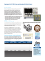
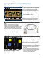
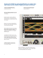
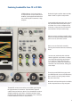
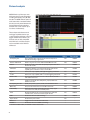
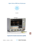
Agilent Infiniium 90000 X-Series Oscilloscopes Data Sheet Combining deep logic analysis with the industry’s highest performance oscilloscope Featuring the world’s fastest mixed signal oscilloscope Engineered for 33 GHz true analog bandwidth that delivers: Need bandwidth? When you’re deploying leading edge high-speed serial bus designs like FibreChannel, SAS 12 G, or 10 Gb Ethernet KR, jitter matters and picoseconds count. When you’re doing spectral analysis of wide-bandwidth RF signals or investigating transient phenomena, bandwidth is critical. You need the most accurate real-time oscilloscope you can get. Agilent Infiniium 90000 X-Series scopes are engineered for 33 GHz true analog bandwidth that delivers: • The industry’s highest real-time scope measurement accuracy • The industry’s only 30 GHz oscilloscope probing system • The industry’s fastest logic analysis on an oscilloscope (16 channels at up to 50 ps timing resolution) 33 GHz and still improving The industry experts have spoken, and the 90000 X-Series is one of the most award-winning oscilloscopes in the history of the oscilloscope industry. With Agilent’s 90000 X-Series oscilloscope, you get up to 33 GHz of real-time bandwidth and the best measurement accuracy. Custom front end technology requiring over five years of design effort yields the fastest real-time oscilloscope hardware available today. Even with all of the 90000 X-Series’ success, Agilent’s software and hardware teams still continue to improve its accuracy and capability. The 90000 X-Series now features a more accurate calibration, PrecisionProbe software, InfiniiView software, and EZJIT Complete; making it the go-to tool for not only your compliance needs, but also your design and validation needs. Need more than just a regular oscilloscope? As part of its continual improvement, 90000 X-Series now has 16 digital channels with time resolution as fast as 50 ps. The mixed signal oscilloscope is the ideal tool for debugging tough memory challenges with unique triggering specific to memory technologies. Analog bandwidth Model number DSAX93204A Sample rate Max Memory 2 channel 4 channel 2 channel 4 channel depth 4 channel 33 GHz 16 GHz 80 GSa/s 40 GSa/s 2 Gpts DSOX93204A 33 GHz 16 GHz 80 GSa/s 40 GSa/s 2 Gpts DSAX92804A 28 GHz 16 GHz 80 GSa/s 40 GSa/s 2 Gpts DSOX92804A 28 GHz 16 GHz 80 GSa/s 40 GSa/s 2 Gpts DSAX92504A 25 GHz 16 GHz 80 GSa/s 40 GSa/s 2 Gpts DSOX92504A 25 GHz 16 GHz 80 GSa/s 40 GSa/s 2 Gpts DSAX92004A 20 GHz 16 GHz 80 GSa/s 40 GSa/s 2 Gpts DSOX92004A 20 GHz 16 GHz 80 GSa/s 40 GSa/s 2 Gpts DSAX91604A 16 GHz 16 GHz 80 GSa/s 40 GSa/s 2 Gpts DSOX91604A 16 GHz 16 GHz 80 GSa/s 40 GSa/s 2 Gpts DSAX91304A 13 GHz 13 GHz 80 GSa/s 40 GSa/s 2 Gpts DSOX91304A 13 GHz 13 GHz 80 GSa/s 40 GSa/s 2 Gpts 2 BW Upgradeable Buy the performance you need today knowing you have the headroom you need for tomorrow with bandwidth upgradability to 33 GHz Engineered for 33 GHz true analog bandwidth that delivers: The industry’s highest real-time scope measurement accuracy. When you’re designing with faster signals, shrinking eyes and tighter jitter budgets errors introduced by your oscilloscope can seriously impact your design margins. The Agilent Infiniium 90000 X-Series scopes deliver the highest measurement accuracy available by offering the following characteristics: • True analog bandwidth to 33 GHz • Lowest oscilloscope noise floor (2.10 mV at 50 mV / div, 33 GHz) • Lowest jitter measurement floor (100 fs) Having the most accurate analog bandwidth and lowest noise floor available means better spectral analysis of transients and wide-bandwidth RF signals. Industry’s first and only 30 GHz oscilloscope probing system. No matter how much bandwidth your scope has, if your probes can’t match the scope’s bandwidth, your measurements are compromised. The Agilent Infiniium 90000 X-Series scopes offer probing solutions that are up to the tough challenges today’s high-speed signal data rates with the following: • InfiniiMax III high frequency probes with automatic AC calibration (PrecisionProbe) • Fully-integrated probe amplifier s-parameter correction • The industry’s first bandwidth-upgradable probe amplifier The industry’s most comprehensive applicationspecific measurement software. When time is of the essence, you need tools that can speed true understanding of your signal activity. From serial bus debug and compliance testing to jitter measurements to sophisticated triggering capability, Agilent stays on top of the test standards and your requirements by working to ensure that you get accurate results more quickly. Easily isolate signals of interest with zone qualified view using InfiniiScan software triggering, just one of more than 40 application-specific software options. The Agilent Infiniium 90000 X-Series scopes offer the following: • The broadest range of jitter, triggering, analysis and display tools • Pre-built compliance testing software based on the expertise of our engineers on the standards committees • Support for emerging technologies including FibreChannel, SAS 12G, or MIPI-MPhy 3 Engineered for 33 GHz true analog bandwidth that now combines deep logic analysis with the industry’s highest performance oscilloscope: 33 GHz true analog bandwidth of the oscilloscope and 80 GSa/s sample rate provides ultra-low noise. Capture your longest signal with up to 25 ms data using 2 Gpt of acquisition memory at 80 GSa/s. See your signal more clearly with a 12.1-inch XGA (1024 x 768) high-resolution color touch screen display. Identify anomalies easily with a 256-level intensity-graded or color-graded persistence display that provides a three dimensional view of your signals. Remote access through 10/100/1000 BaseT LAN interface with web-enabled connectivity uses ultra-responsive Ultra VNC. GPIB and LAN provide remote measurements. Optional Infiniium application remote program interface allows application/compliance software automation. LXI class C compliant. MATLAB support. An additional four USB 2.0 host ports and a USB 2.0 device port on the back panel. Perfect for extra connectivity including an optical drive. A USB 2.0 device port lets you control the scope and transfer data via a USB 2.0 480Mbpts connection. Calibration edge with a rise time of less than 15 ps enables TDT calibration with PrecisionProbe software. Optional x4 PCIExpress slot speeds up offload times by a factor of 5, using socket drivers. Use this option (823) for faster deep offloads of the waveforms. 4 Featuring bandwidths from 13 to 33 GHz 10 MHz reference clock can be input to or output from the scope to allow precise timebase synchronization with more than one oscilloscope, RF instruments or logic analyzers. Dedicated single acquisition button provides better control to capture a unique event. Customizable multipurpose key gives you any five automated measurements with a push of a button. You can also configure this key to execute a script, print/save screen shots, save waveforms or load a favorite setup. Measure section, including a toggling marker button and a dedicated marker knob, provides quick access to your marker control. Quick access to fine/vernier control by pressing the horizontal and vertical sensitivity knobs. Increase your productivity with a familiar Infiniium graphical user interface, including your favorite drag-and-drop measurement icons. Infiniium’s analog-like front panel has a full set of controls color-coded to the waveforms and measurements, making your tasks simple. Three front panel USB 2.0 host ports match your USB keyboard, mouse, and USB memory drive connection for saving setup and data files and screen shots. Removable solid state drive option is available. It offers improved data security and speed. Threaded RF connectors ensure the most reliable signal integrity for high-performance instruments. The AutoProbe II interface combines the tried-and-true, robust 3.5 mm threaded RF connector of Agilent sampling scopes with a convenient automatic torque mechanism (clutch) that ensures a consistent 8 in. lbs. connection is made without the hassles of a torque wrench. 5 Engineered for 33 GHz true analog bandwidth that delivers: The Oscilloscope: highest real-time scope measurement accuracy Whether you’re deploying emerging high speed bus technology, identifying spectral content of wide-bandwidth RF signals, or analyzing transient physical phenomena, you need the truest representation of your signals under test. Agilent invested in leading edge technology to bring you the highest real-time oscilloscope measurement accuracy available today. Custom integrated circuits using a proprietary Indium Phosphide (InP) process and breakthrough packaging technology enable industry-leading performance, including the: • Up to 33 GHz of true analog bandwidth • Lowest oscilloscope noise floor • Lowest oscilloscope jitter measurement floor True-analog bandwidth- 33 GHz The engineering of a high-performance real-time oscilloscope front end requires designing pre-amplifiers, triggering capability, and sampling technology, then seamlessly tying them together. Using fine line microcircuit processes and relying extensively on years of experience with RF design, Agilent developed the front end multi-chip modules shown here for the Infiniium 90000 X-Series oscilloscopes. Packaging technology provides excellent high-frequency electrical properties along with superior heat dissipation. It is a key enabling technology block in Agilent’s 90000 X-Series’ high measurement accuracy. Low noise floor One of the keys to measurement accuracy at high bandwidths is minimizing the noise generated by the oscilloscope itself. Agilent utilizes a proprietary Indium Phosphide (InP) integrated circuit process in the design of the Infiniium 90000 X-Series oscilloscopes because other oscilloscope techniques just can’t deliver the necessary combination of high-bandwidth and low noise. Not only does that mean you’re purchasing the best tool today, but it also means you can count on technology leadership from Agilent in the future. 6 Low real-time oscilloscope jitter measurement floor, just got lower (now 100 fs) Oscilloscope bandwidth allows signal rise times to be more accurately depicted. The oscilloscope noise floor directly impacts the y-axis voltage placement of each signal data point. The Infiniium 90000 X-Series scopes combine superiority in these characteristics with extremely low sample clock jitter (< 100 femptoseconds). This ensures the lowest possible contribution to jitter measurements from the scope itself so you’re using your jitter budget on your design. In addition to its low jitter measurement floor, the 90000 X-Series has the industry’s deepest memory with up to 2 Gpts, allowing you to resolve low frequency jitter components in a single measurement. Jitter measurement floor of less than 100 fs The 90000 X-Series now features an even more advanced calibration system known as sine wave cal. This sine wave calibration further lowers spurs caused by ADC interleaving errors and enables lower jitter and higher spurious free dynamic range. Sine wave calibration simply builds on its industry leading accuracy. Better calibration improves spectral purity Agilent oscilloscopes are constantly improving their measurement accuracy. The latest innovation is a new, improved calibration routine that better aligns the sample points of the analog to digital converter. The improved calibration results in higher spurious free dynamic range (SFDR) and effective number of bits (ENOB). For instance, the SFDR is improved by as much as 15 dBC depending on the carrier frequency. The higher SFDR is ideal for making RF and optical measurements where spectral purity is of the utmost importance. Improved SFDR and ENOB also means better jitter performance. Ultimately this means the 90000 X-Series now features the highest SFDR and ENOB of any oscilloscope on the market. Improved calibration improves the spurious free dynamic rang by up to 15 dBc 7 Engineered for 33 GHz true analog bandwidth that delivers: The Industry’s Fastest Mixed Signal Oscilloscope A mixed signal oscilloscope integrates traditional analog channels with 16 digital channels In 1996, Agilent pioneered the mixed signal oscilloscope Innovative IC technology we called ‘MegaZoom,’ which delivered highly responsive deep memory so designers can see both cause and effect in digitally controlled analog phenomena. The first MSO was named Test & Measurement World Test Product of the Year in 1997. Agilent MSOs seamlessly integrate the familiar controls of an oscilloscope with the additional digital data collection and pattern recognition of a logic analyzer. You can trigger across any combination of analog and digital channels; integrate serial bus triggering and decode and even see inside your FPGA designs. Agilent continues to lead the way with MSOs The MSO 90000 X-Series is specifically targeted at the DDR2/3/4 technologies, simplifying the complicated task of debugging memory technologies. The 20 GSa/s on 8 channels means you can easily separate reads and writes on all DDR4 speeds. The MSO 90000 X-Series is fully compatible with Agilent 90-pin logic analysis connectors, making it easy to connect to your devices. Combining analog and digital performance Today’s designs require access to complex triggers and multiple instruments. The 90000 X-Series mixed signal oscilloscopes provide up to 20 channels you can use at once. Each channel can be combined in a unique pattern trigger. The 90000 X-Series has the ability to label each individual channel as part of a bus for decoding, saving hours of manual work. The 90000 X-Series also features application-specific decode applications that are designed for up to 20 channels. These applications include many low-speed serial and parallel busses. For instance, the JTAG protocol decode is available only on Agilent oscilloscopes. 8 Engineered for 33 GHz true analog bandwidth that delivers: Industry’s first 30 GHz oscilloscope probing system To take advantage of your investment in a high-bandwidth oscilloscope, you must have a probing system that can deliver bandwidth to the probe tip. Agilent rises to the challenge of high-speed signal reproduction with these probing innovations: • The industry’s first bandwidth upgradable probe amplifier • Fully-integrated probe amplifier s-parameter correction The InfiniiMax III 30 GHz probing system includes accessories to enable probing with a ZIF tip, browsing, or connecting to 3.5 mm inputs. Fully-integrated probe amplifier s-parameter correction Each InfiniiMax III probe amplifier comes pre-packaged with its own customized characteristics via s-parameter files. The InfiniiMax III probing system and the 90000 X-Series communicate via an I²C bus. This communication allows the 90000 X-Series to download the customized s-parameter files from the InfiniiMax III probing amplifier to the scope for greater accuracy. Industry’s only bandwidth upgradable probes Purchase the probing performance you need today with confidence that you have headroom for the future with Agilent’s InfiniiMax III bandwidthupgradable probes. Upgrade to higher performance at a fraction of the cost of probe bandwidth upgrades. The InfiniiMax III probing system uses the same InP technology that enables high bandwidth and low noise oscilloscope measurements. 9 Analysis tools: PrecisionProbe (option 001) Turn your 90000 X-Series oscilloscope into a time-domain transmissometry (TDT) and quickly characterize and compensate any input into your scope. PrecisionProbe technology turns your oscilloscope into the ultimate characterization tool. Not only can you do the normal de-embedding through InfiniiSim, PrecisionProbe allows quick characterization of your entire probe system (including cables and switches) without the need for extra equipment. PrecisionProbe takes advantage of the fast “cal output” signal on the 90000 X-Series to characterize and compensate for loss on the measurement system. Now every probe and cable in the system can have the exact same frequency response – probe to probe or cable to cable – without measurement variation caused by probe variation. Now you can properly characterize custom probes. In addition to characterizing the cables, PrecisionProbe allows for immediate use on the same instrument. PrecisionProbe saves you time and money while increasing your measurement accuracy. When you combine InfiniiMax probes with switches between the amplifier and the probe head, PrecisionProbe allows for full correction and automation of each probe’s path. Full automation is then available to allow for quick swapping of the inputs via Infiniium’s compliance framework. For increased accuracy, purchase PrecisionProbe Advanced for faster edge speeds and true differential measurements. PrecisionProbe technology: • Properly creates custom probe transfer function =VOut / VIn • Properly characterizes probed system transfer function such that VOut / VInc = VOut / VSrc • Removes unwanted S21 cable insertion loss PCI Express measurement comparisons Agilent’s uses Indium Phosphide to procuce a sub 12 ps edge perfect for characterizing cable and probe frequency response Root complex device Eye height (mV) Eye height PrecisionProbe Gain 2.5 GT/s_12 GHz 517.19 553.94 7.1% 5 GT/s_12 GHz_3.5 dB 312.22 348.19 11.5% 5 GT/s_12 GHz_6 dB 341.1 376 10.2% 5 GT/s_16 GHz_3.5 dB 306.6 348.33 13.6% 5 GT/s_16 GHz_6 dB 344.4 374.41 8.7% 8 GT/s_12 GHz_P7 96.83 103.09 6.5% 8 GT/s_12 GHz_P8 100.16 108.33 8.2% 8 GT/s_16 GHz_P7 96.92 106.01 9.4% 8 GT/s_16 GHz_P8 100.24 108.24 8.0% By characterizing and compensating for cable loss on the cable connected to the PCI Express test fixture, the designer was able to gain between 6.5% and 13.6% margin that would have been lost otherwise. 10 Analysis tools: EZJIT, EZJIT + and SDA (standard on DSA models) Gain insight into the causes of signal jitter to ensure high reliability of your design With faster edge speeds and shrinking data-valid windows in today’s highspeed digital designs, insight into the causes of jitter has become critical for success. Using EZJIT and EZJIT + jitter analysis software the 90000 X-Series oscilloscopes help you identify and quantify jitter components that affect the reliability of your design. Time correlation of jitter to the real-time signal makes it easy to trace jitter components to their sources. Additional compliance views and a measurement setup wizard simplify and automate RJ/DJ separation for testing against industry standards. EZJIT Plus automatically detects embedded clock frequencies and repetitive data patterns on the oscilloscope inputs and calculates the level of data-dependent jitter (DDJ) that is contributed to the total jitter (TJ) PDF by each transition in the pattern, a feature not available on any other realtime oscilloscope today. Measurement trends and jitter spectrum EZJIT’s simple tools help you quickly analyze the causes of jitter. Measurement trends allow you to see deeper views of factors affecting measurements. Jitter spectrum is a fast method to find the causes of jitter. Two ways to separate jitter Use EZJIT software to extract spread spectrum clocks EZJIT + comes with two ways to separate jitter: the industry standard spectral method and the emerging tail-fit method. Both methods allow for simple separation of RJ and DJ, but the tail-fit method provides jitter separation in the unique case of non-symmetrical histograms and aperiodic bounded uncorrelated jitter. Unique RJ/DJ threshold view EZJIT + also provides a unique spectral view of the jitter spectrum with the threshold drawn on the chart. The spectral view provides insight into the decision point of the separation and allows for narrow or wide, tail-fit or Dual-Dirac. Real-time eye and clock recovery The RJ/PJ threshold tools, provides more jitter analysis Serial data analysis (SDA) software provides flexible clock recovery including 1st and 2nd-order PLL and constant algorithms. With a stable clock, you can look at real-time eyes of transition and non-transition bits. 90000 X-Series scopes with SDA software also provide a new unique view of bits preceding an eye. Tools to determine the correct settings SDA, EZJIT, and EZJIT+ come with an array of visual tools to make analyzing the data simple and ensure that the correct settings are chosen for difficult design decisions. For example, the improved bathtub curve (see image to the left) allows an easy visual tool to determine which jitter separation method best fits the data. Jitter separation makes debugging your device easy 11 Analysis tools: EZJIT Complete (standard on DSA models) Discover signal anomalies to the noise of the waveform More than your standard jitter package In order to efficiently determine root cause for any type of signal degradation in the amplitude domain, you must first determine whether the problem is caused by random or deterministic sources. In order to help you accomplish this task, EZJIT Complete takes analysis techniques used in the time domain (jitter analysis) and extends them into the amplitude domain. More than just an eye contour EZJIT Complete is an in-depth view into impairments related to signal levels – either logic ones or logic zeroes – deviating from their ideal positions. Some tools simply provide a view of an eye contour, but provide no real measurement data other than nice graphics. EZJIT Complete uses separation techniques to allow each bit to be examined to determine correlated effects and to make multiple measurements on individual bits to determine uncorrelated effects. Use FFTs to analyze the frequency domain and extract random components. Dual-Dirac modeling techniques are also carried from the jitter domain and used in the interference domain. Key measurements With EZJIT Complete, 90000 X-Series scopes offer the following unique measurements: • Total interference (TI) • Deterministic interference (DI) • Random noise (RN) • Periodic interference (PI) • Inter-symbol interference (ISI) • RIN (dBm or dB/Hz) • Q-factor 12 Analysis tools: InfiniiSim (options 013 and 014) The most advanced waveform transformation software helps you render waveforms anywhere in a digital serial data link InfiniiSim waveform transformation toolset provides the most flexible and accurate means to render waveforms anywhere in a digital serial data link. The highly configurable system modeling enables you to remove the deleterious effects of unwanted channel elements, simulate waveforms with channel models inserted, view waveforms in physically improbable locations, compensate for loading of probes and other circuit elements, and do so simply and quickly on your tool of choice, the 90000 X-Series at up to 33 GHz of bandwidth. Circuit models to define your setup The InfiniiSim waveform transformation toolset provides a graphical user interface for you to define your system as you understand it and even make it arbitrarily complex. You do this by selecting topologies and defining circuit blocks. Model reflections With the InfiniiSim waveform transformation toolset, you can transform signals with confidence, whether you are inserting or removing channel elements or relocating the measurement plane. InfiniiSim’s advanced toolset lets you model up to 27 different elements at once and model the interaction between elements. Only toolsets with the ability to model more than one element will properly reflect a model including the oscilloscope’s input. The 90000 X-Series scopes provide their own s11 parameter to allow modeling of their own input. Model your system with as much detail as you need InfiniiSim features the model setup that best matches your design. Whether it is a simple single-element model or an advanced general-purpose model with up to 27 elements in the link, you can perfectly model your design and simulate the exact probing point you want. 13 Analysis tools: Serial data equalization (option 012) Significantly reduce receiver errors by opening even tightly shut eyes through equalization emulation Serial data equalization for the 90000 X-Series provides fast and accurate equalization using decision feedback equalization (DFE), feed-forward equalization (FFE), and continuoustime linear equalization (CTLE) modeling in real time. Serial data equalization software allows you to input your own self-designated tap values to verify your design. If you prefer, the software will find the optimal tap values for you. CTLE allows DC gain and two-pole modeling. Analysis Tools: InfiniiScan (Option 009) Trigger on events that hardware triggers can’t handle. InfiniiScan software allows you to use an oscilloscope to identify signal integrity issues that hardware triggering is unable to find in your electronic designs. This innovative software scans through thousands of acquired waveforms per second to help you isolate signal anomalies, saving you time and improving designs. Innovative triggers The zone qualify finder allows you to draw a “must pass” or “must not pass” zone on the oscilloscope screen to visually determine the event identify condition. If you can see the event of interest on the screen, you can create a trigger that will isolate it, saving significant time over some complicated hardware triggers. Draw zones on your screen for a unique triggering experience Other triggers include non-monotonic edge, measurement limit search, runt and pulse width. By combining InfiniiScan and hardware-accelerated math, you can even trigger on differential math signals 14 Analysis tools: N8900A InfiniiView oscilloscope analysis software View and analyze away from your scope and target system Ever wish you could do additional signal viewing and analysis away from your scope and target system? Now you can. Capture waveforms on your scope, save to a file, and recall into Agilent’s InfiniiView application. View and analyze anywhere your PC goes Take advantage of large high-resolution and multiple displays found in your office. Use familiar scope controls to quickly navigate and zoom in to any event of interest. Use auto measurements and functions for additional insight. InfiniiView software supports a wide array of Infiniium applications Share scope measurements more easily across your team You can share entire data records instead of being limited exclusively to static screen shots. Create more useful documentation Use features such as right-click cut-and-paste to move screen images between applications, without ever having to save the image to a file. Add up to 100 bookmark annotations and up to 20 simultaneous measurements. Need advanced analysis capability? Use InfiniiVew to find signal anamolies, such as power supply coupling InfiniiView includes a variety of upgrade options including serial decode upgrades for a variety of serial buses, jitter analysis, and serial data analysis. Peak search capability makes InfiniiVew a frequency domain tool 15 Analysis tools: User-defined function (option 065) Combine Infiniium and MATLAB for even more analysis Enhance the 90000 X-Series with a seamless gateway to powerful MATLAB analysis functionality. User-defined function software adds new analysis capabilities to the 90000 X-Series, beyond traditional math/analysis features. Now you have the freedom to develop your own math functions or filters using MATLAB and its Signal Processing Toolbox. With a seamless integration to MATLAB, Agilent Infiniium oscilloscopes allow you to display your math and analysis functions live on the oscilloscope screen, just like any other scope-standard functions. Analysis Tools: complete list of analysis software Analysis Tools Description Option Standalone PrecisionProbe Characterize and compensate for loss from your input to your oscilloscope to 33 GHz 001 N2809A-001 InfiniiScan Trigger on unique events including using zones on multiple channels and non-monotonic edges 009 N5414B EZJIT Basic jitter analysis with measurement trending, time interval error and many more measurements 002* E2681A EZJIT + Get in-depth analysis of your jitter by decomposing your jitter 004* N5400A EZJIT Complete Understand your full real time by decomposing the noise that is impacting your margins 070* N8823A Serial data analysis Recover clocks to 120 Gbs/s and view real-time eyes. Run mask testing 003* E2688A InfiniiSim Basic Waveform transformation software to remove or add three elements in your link 013 N5465A-001 InfiniiSim Advanced Waveform transformation software to remove or add 27 elements in your link 014 N5465A-002 Serial Data Equalization Easily emulate your equalizer settings for CTLE, FFE and DFE 012 N5461A InfiniiView Put your scope onto your PC and maximize Infiniium’s analysis tools with a true offline analysis engine − N8900A User-defined function Create custom functions that run line on your oscilloscope with MathWorks MATLAB software 010 N5430A MATLAB Basic Purchase an introductory MATLAB software package to acquire scope measurements into the MATLAB environment 061 – MATLAB Standard Purchase a typical MATLAB software package, signal processing and filter design toolboxes on the same PO as your scope 062 – User-defined function with MATLAB Create and excute custom fuctions that run live on your oscilloscope. Includes MATLAB standard software (option 062) 065 N8806A Agilent Spectrum Visualizer (ASV) Analyze advanced FFT frequency domain analysis at a cost-effective price - 64996A * Standard on DSA models 16 Compliance and automated testing Today’s demanding environment means you have much less time to understand the intricacies of the technologies you are testing. You also have less time to develop and test automation software that is designed to increase measurement throughput and decrease time to market. Agilent’s compliance applications save you time and money with measurement automation built into the compliance application. No longer do valuable resources need to be exclusively tied to writing automation software – instead they can be deployed to designing the next big project. Compliance applications that run on 90000 X-Series oscilloscopes are certified to test to the exact specifications of each technology standard. If a test passes on the 90000 X-Series scope in your lab, you can be assured that it will pass in test labs and at plug fests worldwide. Agilent experts on technology boards and industry standards committees help define compliance requirements. As a result, you can be sure that 90000 X-Series oscilloscope tools deliver to critical specifications. Setup wizards combined with intelligent test filtering give you confidence you’re running the right tests. Comprehensive HTML reports with visual documentation and pass/fail results guarantee that critical information is retained on each test. Compliance applications make testing to today’s technologies standards easy Quick and easy automated switching Only Agilent’s 90000 X-Series oscilloscopes feature compliance applications with both the user-defined application’s add-in capability and integrated PrecisionProbe compensation. Switch paths can vary in their characteristics and have unwanted loss. By enabling PrecisionProbe in its compliance applications, 90000 X-Series scopes allow you to characterize and compensate for every path in the switch, making every path’s frequency response identical in both magnitude and phase. These tools makes switch automation quick and painless. The 90000 X-Series and its compliance applications make automation more automated than ever. Your technicians no longer need to spend valuable time physically changing connections. The remote programming interface makes it easy to control automation applications via your PC PrecisionProbe is fully integrated in 90000 X-Series automation applications 17 Compliance and automation testing: Switch matrix support Comprehensive testing, eastily achieved Eliminate reconnections (reducing errors) Compliance applications on Agilent’s 90000 X-Series now support a switch matrix, making testing simple by automating test for each lane of a multi-lane bus. Typical testing requires reconnecting the oscilloscope each time that you switch a lane, which causes wasted time and inaccuracies. The 90000 X-Series solves this problem by supporting switch matrix through its compliance test. Simply connect the switch to the oscilloscope and all the lanes, and then hit run to complete full testing of your entire device. Maintain accuracy The framework fully supports Agilent’s PrecisionProbe software (N2809A) and InfiniiSim software (N5465A). This gives you the ability to characterize every switch path to the device under test (both magnitude and skew) and ensure that all of them maintain the same level of accuracy. Customize your testing Use the remote programming interface (standard feature on the 90000 X-Series) and N5467A user-defined application for device control, instrument control and test customization. Clock SMA probe head Ch1 L1 SMA probe head Ch2 L2 SMA probe head Ch3 L3 SMA probe head Ch4 DUT Switch matrix Scope +3.3V Typical switch configuration for HDMI testing (now supported in the 90000 X-Series) 18 Skews between switch paths are easily maintained with Agilent’s unique software Compliance and automation testing: User-defined application (option 040) Custom automation for your 90000 X-Series oscilloscope The user-defined application is the only fully-customizable automated environment made for an oscilloscope by an oscilloscope designer. It provides full automation, including the ability to control other Agilent instruments, external applications such as MATLAB and your DUT software. Simplify your automation The user-defined application (UDA) makes automation simple. The application takes the Infiniium compliance application framework and gives you full access to its interface. UDA allows for automation testing in as little as one minute. Use UDA to control other Agilent instruments such as signal generators and network analyzers to create a full suite of measurements. Full measurement report No automation would be complete without a simple-to-view and easyto-understand report. UDA provides a full report of the pass/fail criteria you have provided. Add-in capability Ever wanted to add testing to your compliance applications? All Infiniium compliance applications support the industry’s most flexible testing mechanism with UDA add-in capability. Create the custom testing you need and then plug it into your compliance application to expand the application to your testing needs. UDA add-in capability is only available on Infiniium oscilloscopes. PrecisionProbe and switch compatibility UDA makes automation of switches in your system simple and accurate. Use PrecisionProbe to characterize the unique GUI switch between every input path of the switch and then let UDA’s in your switch system. Every input can look identical in its frequency response thanks to this advanced technology. 19 Compliance and automation testing: Other options on 90000 X-Series oscilloscopes In the previous pages we have highlighted a few of the key technologies that benefit from the industry’s most accurate oscilloscope. The 90000 X-Series offers more than 20 compliance applications, and the list continues to grow. All applications are fully compatible with InfiniiSim, PrecisionProbe and UDA’s unique add-in capability. Compliance tools Description PCI Express gen 1/2/3 Guarantee your PCI Express gen3 designs 044 N5393C HDMI 2.0 compliance Quickly verify and debug your high-definition multimedia interface 077 N5399C SAS -2 compliance Automatically execute SAS electrical checklist tests at each of the IT, CT, IR and CR interface points 043 N5412A SAS -3 compliance Automatically execute SAS-3 electrical checklist tests 076 N5412C DisplayPort source compliance Verify and debug your DisplayPort interface designs for sink and source ICs, motherboard systems, computers and graphics cards 045 U7232B DDR1 verification Save time with automated testing based on JEDEC DDR1 and LPDDR1 specifications 031 U7233A DDR3 verification Save time with automated testing based on JEDEC DDR3 and LPDDR3 specifications 032 U7231B DDR2 verification Save time with automated testing based on JEDEC DDR2 and LPDDR2 specifications 033 N5413B DDR4 verification Save time with automated testing based on JEDEC DDR4 specifications 058 N6462A MIPI D-Phy verification Execute D-Phy electrical checklist tests for CSI and DSI architectures 035 U7238B GDDR5 verification Save time with automated testing based on JEDEC GDDR5 specification − U7245A MIPI M-Phy verification Execute M-Phy electrical tests 047 U7249B Energy Efficient Ethernet Debug your 1000BASE-T, 100BASE-TX and 10BASE-T Ethernet designs 060 N5392B 10 Gbase-T compliance Coverage of the 10GBASE-T transmitter electrical specifications as described in section 55.5.3 of IEEE 802.3an-2006 036 U7236A XAUI compliance XAUI validation with 10GBASE-CX4, CPRI, OBSAI and Serial RapidIO support 030 N5431A SATA 6G compliance Automated compliance testing for 1.5-Gbps, 3.0-Gbps and 6.0-Gbps SATA and eSATA transmitter (PHY/TSG/OOB tests) 038 N5411B User-defined application Fully customizable automated application for your Infiniium oscilloscope 040 N5467A USB 2.0 compliance USB-IF recognized compliance for low/full and low/full/high-speed USB automated electrical test 029 N5416A USB 3.0 compliance Validate and debug your USB 3.0 silicon, host, hub or device 041 U7243A USB HSIC Validate and debug USB high-speed inter-connect devices 046 U7248A MHL compliance Validates MHL source designs as found in portable products such as cell phones and tablets according to the MHL 1.2 standard 054 N6460A Thunderbolt compliance Measure the transmitter with the accuracy of the 90000 X-Series 059 N6463A 20 Option Standalone Protocol and triggering: Memory support (standard feature on the MSOX) DDR2, 3, and 4 protocol and triggering Because of the introduction of MSO models on the 90000 X-Series, these oscilloscopes now support full protocol and triggering for DDR2, 3 and 4 technologies. The 90000 X-Series allows for full triggering on the following events: read, write, activate, precharge, and many more common memory commands. The triggering makes read and write separation easy to do; it also helps you quickly find real time eyes in today’s difficultto-debug memory environment. The DDR2, 3 and 4 protocol triggering is only available on the MSO and comes standard with an MSO purchase. LPDR 2 and 3 protocol and search The 90000 X-Series also provides LPDDR2 and LPDDR3 protocol standard on its MSO. A time-aligned listing window makes it easy to search for uncommon events. 21 Protocol analysis 90000 X-Series oscilloscopes come with more than 15 protocol decoders, including the industry’s only 64/66b decoder. The 90000 X-Series protocol tools feature time-correlated markers that let you easily move between the listing window and the waveform. Protocol tools can be used on up to four lanes simultaneously. These unique tools feature search and trigger capability that lets you scan through the waveform to find the trigger condition that interests you. Protocol tools are fully compatible with Infiniium’s serial data analysis and are available on the Infiniium offline tool. Protocol Description PCI Express gen3 Time-correlated views of physical and transaction layer errors. 128/130-bit decoding on gen3 traffic 049 N8816A Ethernet 10Gbase-KR World’s only protocol tool for 10Gbase-KR 64/66-bit decoder 048 N8815A USB 3.0 Set up your scope to show USB 3.0 SuperSpeed protocol decode in less than 30 seconds SATA/SAS Simplify the validation of your SATA/SAS designs with the fullcapability protocol viewer for 3 G, 6 G and 12 Gbit/s 018 N5436A DigRF v4 Extend your scope capability with DigRF v4 triggering and decode 051 N8807A I2C/SPI Extend your scope capability with I2C and SPI triggering and decode 007 N5391A RS232/UART Easily view the information sent over an RS-232 RS-422, RS-485 or other UART serial buses 015 N5462A USB 2.0 Trigger on and quickly view USB packets, payload, header and detailed information 016 N5464A PCI Express gen1 and 2 Quickly view packets, payload, header, and detailed information 017 N5463A MIPI D-Phy Easily view the information sent over MIPI serial buses 019 N8802A CAN/FlexRay View both protocol-layer information and physical-layer signal characteristics for CAN, LIN and FlexRay buses 063 N8803A JTAG Eliminate the difficult task of manually determining JTAG TAP controller states, instruction and data register decode 042 N8817A SVID Decode and search on SVID technology 056 N8812A Unipro decode Decode at the protocol level 052 − DDR2/3/4 Trigger and search on difficult-to-find events −* − LPDDR2/3 Decode and search on LPDDR2/3 technology −* − * Standard on MSO models, not available on DSO or DSA models 22 Option Part number N8805A Agilent Infiniium Oscilloscope Portfolio Agilent’s Infiniium oscilloscope lineup includes bandwidths from 600 MHz to 63 GHz. Use the following selection guide to determine which best matches your specific needs. All Infiniium real-time oscilloscopes feature the following: • World’s highest bandwidth on 4 channels in a single frame • Industry’s lowest noise floor • Full PrecisionProbe compatibility 9000 Series Up to 4 GHz Available bandwidths 600 MHz, 1 GHz, 2.5 GHz, 4 GHz 6 to 16 GHz 90000A Series 6 GHz, 8 GHz 12 GHz, 13 GHz 20 to 63 GHz Max upgradable bandwidth 4 GHz 90000 X-Series 90000 Q-Series 2.5 GHz, 4 GHz, 13 GHz 13 GHz, 16 GHz 20 GHz, 25 GHz, 28 GHz, 33 GHz 20 GHz, 25 GHz, 33 GHz, 50 GHz, 63 GHz 33 GHz 63 GHz Sample rate (2-channel/4-channel) 10/20 GSa/s 40/40 GSa/s 80/40 GSa/s 160/80 GSa/s Channel inputs and connector types 50Ω and 1 MΩ, BNCs 50 Ω, BNCs 50 Ω, 2.92 and 3.5 mm SMAs 50Ω, 1.85 mm, 2.4, mm 2.92 and 3.5 mm, SMAs Memory depth (standard/max) 20 M/1 Gpts 20 M/2 Gpts 20 M/2 Gpts 20 M/2 Gpts MSO models Yes No Yes No Supported InfiniiMax probe families InfiniiMax 2 InfiniiMax 2 InfiniiMax 3 InfiniiMax 2 with adapter InfiniiMax 3 InfiniiMax 2 with adapter 23 Engineered for 33 GHz true analog bandwidth that delivers Configure your high performance real-time oscilloscope solution today Get the most out of your oscilloscope investment by choosing options and software to speed your most common tasks. Configure your Infiniium X-Series oscilloscope in three easy steps. Use option numbers when ordering at time of purchase. Use model numbers to add to an existing scope. 1. Choose your oscilloscope, memory and options Mainframe: Oscilloscopes Description DSAX93204A 33 GHz Signal Analyzer* DSOX93204A 33 GHz Digital Signal Oscilloscope MSOX93204A 33 GHz Mixed Signal Oscilloscope DSAX92804A 28 GHz Signal Analyzer* DSOX92804A 28 GHz Digital Signal Oscilloscope MSOX92804A 28 GHz Mixed Signal Oscilloscope DSAX92504A 25 GHz Signal Analyzer* DSOX92504A 25 GHz Digital Signal Oscilloscope MSOX92504A 25 GHz Mixed Signal Oscilloscope DSAX92004A 20 GHz Signal Analyzer* DSOX92004A 20 GHz Digital Signal Oscilloscope MSOX92004A 20 GHz Mixed Signal Oscilloscope DSAX91604A 16 GHz Signal Analyzer* DSOX91604A 16 GHz Digital Signal Oscilloscope MSOX91604A 16 GHz Mixed Signal Oscilloscope DSAX91304A 13 GHz Signal Analyzer* DSOX91304A 13 GHz Digital Signal Oscilloscope MSOX91304A 13 GHz Mixed Signal Oscilloscope All models come with power cord, keyboard, mouse, stylus, calibration cable, wrench and (5) coax adapters.** * DSA models come with 50 Mpts memory, EZJIT, EZJIT+, EZJIT Complete, and Serial Data Analysis standard. ** 13, 16 and 20 GHz models come with adapters rated to 25 GHz (1250-3758), all other models come with adapters rated to 35 GHz (5061-5311). *** 13 GHz models include two N5442A adapters Memory: 24 Description Options Model number 20 Mpts/ch memory Standard 50 Mpts/ch memory DSOX90000A-050 N2810A-050 100 Mpts/ch memory DSOX90000A-100 N2810A-100 200 Mpts/ch memory DSOX90000A-200 N2810A-200 500 Mpts/ch memory DSOX90000A-500 N2810A-500 1 Gpts/ch memory DSOX90000A-01G N2810A-01G 2 Gpts/ch memory DSOX90000A-02G N2810A-02G Engineered for 33 GHz true analog bandwidth that delivers Configure your high performance real-time oscilloscope solution today 1. Choose your oscilloscope, memory and options (Continued) Options: Description Options Model number ANSI Z540 Compliant calibration DSOX90000-A6J ISO17025 calibration DSOX90000-1A7 DVD RW DSOX90000-820 N5473A GPIB card-interface DSOX90000-805 82350B PCI Express card-interface DSOX90000-823 N4866A Performance verification de-skew fixture DSOX90000-808 N5443A Rack mount kit option DSOX90000-1CM N5470A Removable solid state drive with Windows 7 DSOX90000-801 Additional removable solid state drive with Windows 7 (requires option 801) N2892A 2(a). Choose your probes and accessories Description Oscilloscopes 30 GHz InfiniiMax III probe amp N2803A 25 GHz InfiniiMax III probe amp N2802A 20 GHz InfiniiMax III probe amp N2801A 16 GHz InfiniiMax III probe amp N2800A ZIF probe head N5439A Browser (hand held) probe head N5445A 16 GHz solder-in probe head N5441A 26 GHz solder-in probe head N2836A 3.5 mm/2.92-mm/SMA probe head N5444A 450 Ω ZIF tip replacement (set of 5) N5440A 250 Ω ZIF tip replacement (set of 5) N5447A 25 GHz PC board ZIF tip N2838A Browser tip replacement (set of 4) N5476A PV/deskew fixture N5443A Precision BNC adapter (50 ohm) N5442A Sampling scope adapter N5477A 2.92 mm head flex cable N5448A High impedance probe adapter N5449A For more information about Agilent’s InfiniiMax III probing system, check out the InfiniiMax III data sheet with the Agilent literature number, 5990-5653EN. 2(b). Choose MSO options Description Oscilloscopes Flying lead set E5382A Single-ended soft touch connectorless probe E5390A 1/2 size soft touch connectorless probe E5398A Differential soft touch probe E5387A 25 Engineered for 33 GHz true analog bandwidth that delivers Configure your high performance real-time oscilloscope solution today 3. Choose your measurement-specific application software Measurement, Analysis and Decode Software Packages Compliance Testing and Validation Software Packages Description Product number Model number PrecisionProbe software DSOX90000-001 N2809A-001 CAN/FlexRay decode DSOX90000-063 N8803A EZJIT jitter analysis software DSOX90000-002 E2681A EZJIT Plus jitter analysis software DSOX90000-004 N5400A EZJIT Complete analysis software DSOX90000-070 N8823A High-Speed SDA and clock recovery DSOX90000-003 E2688A I2C/SPI DSOX90000-007 N5391A Decode InfiniiScan software triggering DSOX90000-009 N5414B InfiniiSim basic signal de-embedding DSOX90000-013 N5465A-001 InfiniiSim advanced signal de-embedding DSOX90000-014 N5465A-002 Serial data equalization DSOX90000-012 N5461A MATLAB - Basic digital analysis package DSOX90000-061 MATLAB - Standard digital analysis package DSOX90000-062 64b/66b 10Gbase-KR Ethernet Decode DSOX90000-046 N8815A MIPI D-PHY protocol DSOX90000-019 N8802A PCI-Express protocol DSOX90000-017 N5463A RS-232/UART decode DSOX90000-015 N5462A SATA/SAS protocol DSOX90000-018 N8801A USB protocol DSOX90000-016 N5464A User-defined function DSOX90000-010 N5430A Description Product Number Model number DDR1 and LPDDR compliance DSOX90000A-031 U7233A DDR2 and LPDDR2 compliance DSOX90000A-033 N5413B DDR3 up to 1660 MHz compliance DSOX90000A-032 U7231A DisplayPort compliance application DSOX90000A-028 U7232A Ethernet compliance application N5392A HDMI compliance application DSOX90000A-023 N5399A MIPI D-PHY compliance application DSOX90000A-035 U7238A PCI Express compliance application DSOX90000A-022 N5393B SAS compliance application DSOX90000A-027 N5412A SATA 6Gb/s compliance DSOX90000A-038 N5411B USB 3.0 compliance software DSOX90000A-041 U7243A User-defined application DSOX90000A-040 N5467A Xaui compliance application 26 N5431A 10GBASE-T Ethernet automated test application DSOX90000A-036 U7236A SAS-2 compliance test software DSOX90000A-043 N5412B PCI Express compliance test software for PCIe 1.0/2.0/3.0 DSOX90000A-004 N5393C BroadR-Reach compliance DSOX90000A-065 N6467A MOST compliance DSOX90000A-073 N6466A Engineered for 33 GHz true analog bandwidth that delivers Configure your high performance real-time oscilloscope solution today Upgrade your oscilloscope after purchase Bandwidth upgrades N5471M 13 GHz to 16 GHz Bandwidth upgrade N5471G 16 GHz to 20 GHz Bandwidth upgrade N5471H 20 GHz to 25 GHz Bandwidth upgrade N5471I 25 GHz to 28 GHz Bandwidth upgrade N5471J 28 GHz to 33 GHz Bandwidth upgrade Memory upgrades N2810A-050 Upgrade 20 Mpts/ch to 50 Mpts/ch memory N2810A-100 Upgrade 50 Mpts/ch to 100 Mpts/ch memory N2810A-200 Upgrade 100 Mpts/ch to 200 Mpts/ch memory N2810A-500 Upgrade 200 Mpts/ch to 500 Mpts/ch memory N2810A-01G Upgrade 500 Mpts/ch to 1 Gpts/ch memory N2810A-02G Upgrade 1 Gpts/ch to 2 Gpts/ch memory Operating systems upgrades N2753A Windows 7 for Infiniium 90000 X-Series Logic analysis upgrades N2834A MSO upgrade for the 90000 X-Series 27 Infiniium 90000 X-Series Oscilloscopes Performance characteristics Vertical Input channels Four Analog bandwidth (–3 dB)*, 2 channel 2 channel* 4 channel 91304A 13 GHz 13 GHz 13 GHz 91604A 16 GHz 16 GH 16 GHz 92004A 20 GHz 20 GHz 16 GHz 92504A 25 GHz 25 GHz 16 GHz 92804A 28 GHz 28 GHz 16 GHz 93204A 33 GHz 32 GHz 16 GHz Rise time/fall time 10 - 90% 20 - 80% 91304A 32 ps 23 ps 91604A 28.5 ps 21.5 ps 92004A 20 ps 15 ps 92504A 17.5 ps 13 ps 92804A 14.4 ps 11 ps 93204A 12.5 ps 9 ps Input impedance3 50 Ω, ± 3% Sensitivity2 1 mV/div to 1 V/div Full scale hardware sensitivity 60 mV to 8 V Input coupling DC Vertical resolution1 8 bits, ≥ 12 bits with averaging Channel to channel isolation (any two channels with equal V/div settings) DC to 16 GHz: 40 dB 16 GHz to BW: 35 dB DC gain accuracy* ± 2% of full scale at full resolution channel scale (± 2.5% for 5mV/div) Maximum input voltage ±5V Offset range Vertical sensitivity 0 mV/div to ≥ 49 mV/div > 50 mV/div to ≥ 100 mV/div > 100 mV/div to ≥ 199 mV/div > 200 mV/div to ≥ 499 mV/div > 500 mV/div Offset accuracy* ≤ 3.5 V: ± (2% of channel offset + 1% of full scale + 1 mV) > 3.5 V: ± (2% of channel offset + 1% of full scale) Dynamic range ± 4 div from center screen DC voltage measurement accuracy Dual cursor: ± [(DC gain accuracy) + (resolution)] Single cursor: ± [(DC gain accuracy) + (offset accuracy) + (resolution/2)] RMS noise floor (scope only) Volts/div (mVrms) 10 mV 50 mV 100 mV 1V 91304A 0.28 1.10 2.30 21.2 %FS Noise @ 50mV/div 91604A 0.35 1.34 2.63 26.65 Available offset ± 0.4 V ± 0.7 V ± 1.2 V ± 2.2 V ± 2.4 V 92004A 0.43 1.53 3.02 30.05 92504A 0.50 1.76 3.39 34.15 92804A 0.53 1.86 3.62 36.57 93204A 0.60 2.10 3.98 39.92 13 GHz 16 GHz 20 GHz 25 GHz 28 GHz 33 GHz 0.295% 0.335% 0.383% 0.440% 0.465% 0.525% * Denotes warranted specifications, all others are typical. Specifications are valid after a 30-minute warm up period, and ± 5° C from annual calibration temperature 1. Vertical resolution for 8 bits = 0.4% of full scale, for 12 bits = 0.024% of full scale. 2. Full scale is defined as 8 vertical divisions. Magnification is used below 7.5 mV/div. Below 7.5 mV/div, full-scale is defined as 60 mV/div. The major scale settings are 5mV, 10mV, 20mV, 50mV, 100mV, 200mV, 500mV, and 1V. 3. Input impedance is valid when V/div scaling is adjusted to show all waveform vertical values within scope display. 28 Infiniium 90000 X-Series Oscilloscopes Performance characteristics Vertical: digital channels On all MSO models Input channels 16 digital channels Threshold groupings 2 individual threshold settings (1 for channels 0-7 and 1 for channels 8-15) Threshold selections TTL (1.4V), CMOS, (2.5V), ECL (-1.3V), PECL (3.7V), user defined (±3.00 V in 100 mV increments) Maximum input voltage ±40 V peak CAT I Threshold accuracy ±(100 mV + 3% of threshold setting) Input dynamic range ±10 V about threshold Minimum input voltage swing 400 mV peak-to-peak Input impedance (flying leads) 100 kΩ ± 2% (~ 8 pF) at probe tip Resolution 1 bit Analog bandwidth 3 GHz (depends on probing) Horizontal Main timebase range 2 ps/div to 20 s/div real-time Main timebase delay range 200 s to –200 s real-time Zoom timebase range 1 ps/div to current main time scale setting Channel deskew ±1 ms range, 10 fs resolution Time scale accuracy* ± [0.1 ppm (immediately after calibration) ±0.1 ppm/year (aging)] Delta-time measurement accuracy Absolute, averaging disabled Absolute, > – 256 averages Sample Clock Jitter 2 Noise 2 5⋅ + SampleClock Jitter + SlewRate 2 0.35 ⋅ Noise + SampleClock Jitter 2 + SlewRate TimeScaleAccy Reading sec rms 2 TimeScaleAccy Reading sec rms 2 Acquired Time Range Internal Timebase Reference External Timebase Reference 10 ms 100 fs rms 100 fs rms 10 ms - 100 ms 190 fs rms 190 fs rms 100 ms - 1 sec 500 fs rms 190 fs rms > 1 sec 190 fs rms Jitter measurement floor (6a, 6b, 6c) TIE: Noise SlewRate 2 2 + SampleClock Jitter sec rms Periodic Jitter: 2 Noise 2 2⋅ + SampleClock Jitter SlewRate sec rms Cycle-Cycle: 2 Noise 3⋅ + SampleClock Jitter SlewRate 2 sec rms 29 Infiniium 90000 X-Series Oscilloscopes Performance characteristics Acquisition Maximum real-time sample rate 91304A 91604A (2 channels) 80 GSa/s 80 GSa/s 80 GSa/s 80 GSa/s 80 GSa/s 80 GSa/s (4 Channels) 40 GSa/s 40 GSa/s 40 GSa/s 40 GSa/s 40 GSa/s 40 GSa/s Memory depth per channel Standard 92004A 92504A 92804A 93204A 20 Mpts on 4 channels 40 Mpts on 2 channels Option 050 50 Mpts on 4 channels (standard on DSA models) 100 Mpts on 2 channels Option 100 100 Mpts on 4 channels 200 Mpts on 2 channels Option 200 200 Mpts on 4 channels 400 Mpts on 2 channels Option 500 500 Mpts on 4 channels 1 Gpt on 2 channels Option 01G 1 Gpts on 4 channels 1 Gpt on 2 channels Option 02G 2 Gpts on 4 channels 2 Gpts on 2 channels Maxium acquired time at highest real time resolution Real-time resolution 40 Gsa/s 80 Gsa/s Standard 0.5 mS 0.5 mS Option 050 1.25 mS 1.25 mS Option 100 M 2.5 mS 2.5 mS Option 200 M 5 mS 5 mS Option 500 M 12.5 mS 12.5 mS Option 01G 25 mS 12.5 mS Option 02G 50 mS 25 mS Acquisition: digital channels Maximum real time sample rate 10 GSa/s at 16 channels, 20 GSa/s at 8 channels Maximum memory depth per channel Up to 1 Gpt Minimum width glitch detection 50 pS Sampling modes Real-time Successive single shot acquisitions Real-time with averaging Averages are selectable from 2 to 65534 Real-time with peak detect 80 GSa/s in half channel mode, 40 GSa/s in full channel mode Real-time with hi resolution Real-time boxcar averaging reduces random noise and increases resolution Guassian magnitude, linear phase Slower filter roll off while mantaining linear phase Roll mode Scrolls sequential waveform points across the display in a right-to-left rolling motion. Works at sample rates up to 10 MSa/s with a maximum record length of 40 Mpts Segmented memory Captures bursting signals at max sample rate without consuming memory during periods of inactivity Number of segments (Up to 524,288 with option 02G) Maximum time between triggers is 562,950 seconds Re-arm time: 4.5µs Maximum memory depth: Up to 4 Gpts in 1/2 channel mode with option 02G Filters Sin(x)/x Interpolation 30 On/off selectable FIR digital filter. Digital Signal Processing adds points between aquired data points to enhance measurement accuracy and waveform display Infiniium 90000 X-Series Oscilloscopes Performance characteristics Hardware trigger Sensitivity Edge trigger bandwidth Internal low: 2.0 div p-p 0 to 22 GHz Internal high: 0.3 div p-p 0 to 18 GHz, 1.0 div p-p 0 to 22 GHz Auxiliary: 2.5 GHz >20 GHz Minimum pulse width trigger Hardware 250 ps Software (InfiniiScan) 40 ps Level range Internal Auxillary ± 4 div from center screen or ± 4 Volts, whichever is smallest ± 5 V, also limit input signal to ± 5V Sweep modes Single, segmented, and continuous Display jitter (displayed trigger jitter) 50 fs Trigger sources Channel 1, Channel 2, Channel 3, Channel 4, aux, and line Trigger modes Edge Triggers on a specified slope (rising, falling or alternating between rising and falling) and voltage level on any channel or auxiliary trigger. Edge trigger bandwidth is > 20 GHz. Edge transition Trigger on rising or falling edges that cross two voltage levels in > or < the amount of time specified. Edge transition setting from 250 ps. Edge then edge (time) The trigger is qualified by an edge. After a specified time delay between 10 ns to 10 s, a rising or falling edge on any one selected input will generate the trigger. Edge then edge (event) The trigger is qualified by an edge. After a specified delay between 1 to 16,000,000 rising or falling edges, another rising or falling edge on any one selected input will generate the trigger Glitch Triggers on glitches narrower than the other pulses in your waveform by specifying a width less than your narrowest pulse and a polarity. Triggers on glitches as narrow as 125 ps. Glitch range settings: < 250 ps to < 10 s. Line Triggers on the line voltage powering the oscilloscope. Pulse width Triggers on a pulse that is wider or narrower than the other pulses in your waveform by specifying a pulse width and a polarity. Triggers on pulse widths as narrow as 125 ps. Pulse width range settings 250 ps to 10 s. Trigger point can be “end of pulse” or “time out.” Runt Triggers on a pulse that crosses one threshold but fails to cross a second threshold before crossing the first again. Can be time qualified with minimum setting of 250 ps. Timeout Triggers when a channel stays high, low, or unchanged for too long. Timeout setting: from 250 ps to 10 s. Pattern/pulse range Triggers when a specified logical combination of the channels is entered, exited, present for a specified period of time or is within a specified time range or times out. Each channel can have a value of high (H), low (L) or don’t care (X). State Pattern trigger clocked by the rising, falling or alternating between rising and falling edge of one channel. Window Triggers on an event associated with a window defined by two-user adjustable thresholds. Event can be window “entered,” “exited,” “inside (time qualified),” or “outside (time qualified)” voltage range. Trigger point can be “cross window boundary” or “time out.” Time qualify range: from 250 ps to 10 s. 31 Infiniium 90000 X-Series Oscilloscopes Performance characteristics Hardware trigger (Continued) Video Triggers from negative sync composite video, field 1, field 2, or alternating fields for interlaced systems, any field, specific line, or any line for interlaced or non-interlaced systems. Supports NTSC, PAL-M (525/60), PAL, SECAM (625/50), EDTV (480p/60), EDTV (576p/50), HDTV (720p/60), HDTV (720p/50), HDTV (1080i/60), HDTV (1080i/50), HDTV (1080p/60), HDTV (1080p/50), HDTV (1080p/30), HDTV (1080p/25), HDTV (1080p/24), and user-defined formats. Trigger sequences Three stage trigger sequences including two-stage hardware (Find event (A) and Trigger event (B)) and one-stage InfiniiScan software trigger. Supports all hardware trigger modes except “edge then edge” and “video,” and all InfiniiScan software trigger modes. Supports “delay (by time)” and “reset (by time or event)” between two hardware sequences. The minimum latency between “find event (A)” and “trigger event (B)” is 3 ns. Trigger qualification AND qualifier Single or multiple channels may be logically qualified with any other trigger mode. Trigger holdoff range 100nS to 10s Trigger actions Specify an action to occur and the frequency of the action when a trigger condition occurs. Actions include e-mail on trigger and execute “multipurpose” user setting. Software trigger (requires InfiniiScan event identification software – Option 009) Trigger modes Zone qualify Software triggers on the user defined zones on screen. Zones can be specified as either “must intersect” or “must not intersect.” Up to eight zones can be defined across multiple channels. Generic serial Software triggers on NRZ-encoded data up to 8.0 Gbps, up to 80-bit pattern. Support multiple clock data recovery methods including constant frequency, 1st-order PLL, 2nd-order PLL, explicit clock, explicit 1st-order PLL, explicit 2nd-order PLL, Fibre Channel, FlexRay receiver, FlexRay transmitter (requires E2688A except for the constant frequency clock data recovery mode). Measurement limit Software triggers on the results of the measurement values. For example, when the “pulse width” measurement is turned on, InfiniiScan measurement software trigger triggers on a glitch as narrow as 75 ps. When the “time interval error (TIE)” is measured, InfiniiScan can trigger on a specific TIE value. Non-monotonic edge Software triggers on the non-monotonic edge. The non-monotonic edge is specified by setting a hysteresis value. Runt Software triggers on a pulse that crosses one threshold but fails to cross a second threshold before crossing the first again. Unlike hardware runt trigger, InfiniiScan runt trigger can be further qualified via a hysteresis value. Trigger: digital channels MSO models Threshold range (user defined) ±8.0 V in 100-mV increments Threshold accuracy ±(100 mV + 3% of threshold setting) 32 Infiniium 90000 X-Series Oscilloscopes Performance characteristics Maximum measurement update rate > 50,000 measurement/sec (one measurement turned on) > 250,000 measurement/sec/measurement (ten measurements turned on) Measurement modes Standard, Measure all edges mode Waveform measurements Voltage Peak to peak, minimum, maximum, average, RMS, amplitude, base, top, overshoot, preshoot, upper, middle, lower, overshoot, V preshoot, crossing, Pulse base, pulse amplitude, burst interval Time Rise time, fall time, positive width, negative width, burst width, Tmin, Tmax, burst period, Tvolt, + pulse count, - pulse count, burst and burst interval Clock Period, frequency, duty cycle to duty cycle Data Setup time, hold time Mixed Area, slew rate Frequency domain Level qualiication FFT frequency, FFT magnitude, FFT delta frequency, FFT delta magnitude, peak detect mode, amplitude modulation Any channels that are not involved in a measurement can be used to level-qualify all timing measurements Eye-diagram measurements Eye height, eye width, eye jitter, crossing percentage, Q factor, and duty-cycle distortion Jitter analysis measurements Clock Requires Option 002 (or E2681A), 004 (or N5400A), or 070 (or N8823A). Standard on DSA Series Time interval error, N-period, period to period, positive width to positive width, neg width to neg width, and duty cycle to duty cycle Time interval error, unit interval, N Unit Interval, unit interval to unit interval, Data rate, CDR, de-emphasis Data Jitter separation** Spectral Method (narrow and wide), tailfit Measurements** Random Jitter (RJ), Deterministic Jitter (DJ), Aperiodic Bounded Uncorrelated Jitter (ABUJ), periodic jitter, data dependent jitter (DDJ), duty cycle distortion (DCD), Intersymbol Interference (ISI) Fixed measurements** Ability to fix random jitter (Rj) for cross-talk measurements Statistics Displays the current, mean, minimum, maximum, range (max-min), standard deviation, number of measurements value for the displayed automatic measurements Histograms Source Waveform or measurement Orientation Vertical (for timing and jitter measurements) or horizontal (noise and amplitude change) modes, regions are deined using waveform markers Measurements Mean, standard deviation, mean ± 1, 2, and 3 sigma, median, mode, peak-to-peak, min, max, total hits, peak (area of most hits), X scale hits, and X offset hits Mask testing Allows pass/fail testing to user-deined or Agilent-supplied waveform templates. Automask lets you create a mask template from a captured waveform and deine a tolerance range in time/voltage or screen divisions. Test modes (run until) include test forever, test to speciied time or event limit, and stop on failure. Executes “multipurpose” user setting on failure. “Unfold real time eye” feature will allow individual bit errors to be observed by unfolding a real time eye when clock recovery is on. Communications mask test kit option provides a set of ITU-T G.703, ANSI T1.102, and IEEE 802.3 industry-standard masks for compliance testing. * Requires the purchase of User Defined Function (option 010) ** Requires purchase of DSA or EZJIT+ or EZJIT Complete software 33 Infiniium 90000 X-Series Oscilloscopes Performance characteristics Waveform math Number of functions Sixteen Hardware accelerated math Differential and Common Mode Operations/functions Absolute value, add, average, Butterworth*, common mode, differentiate, divide, FFT magnitude, FFT phase, FIR*, high pass ilter, histogram, integrate, invert, LFE*, low pass ilter (4th-order Bessel Thompson ilter), measurement trend, magnify, max, min, multiply, RT Eye*, smoothing, SqrtSumOfSquare*, square, square root, subtract, versus, and optional user deined function (Option 010) Measurement gating Supports up to 16 horizontal measurement gates FFT Frequency range DC to 40 GHz (at 80 GSa/s) or 20 GHz (at 40 GSa/s) Frequency resolution Sample rate/memory depth = resolution Window modes Hanning, lattop, rectangular, Blackman-Harris Measurement modes Automatic measurements Multipurpose Drag-and-drop measurement ...toolbar Measure menu access to all measurements, up to ten measurements can be displayed simultaneously Front-panel button activates up to ten pre-selected or up to ten user-deined automatic measurements Measurement toolbar with common measurement icons that can be dragged and dropped onto the displayed waveforms Snapshot Takes 29 snap shot measurements (customizable) Marker modes Manual markers, track waveform data, track measurements Display Display 12.1-inch color XGA TFT-LCD with touch screen Intensity grayscale 256-level intensity-graded display Resolution XGA 1024 pixels horizontally x 768 pixels vertically Annotation Up to 12 labels, with up to 100 characters each, can be inserted into the waveform area Grids Up to 16 waveform grids, each with 8-bit vertical resolution Waveform styles Connected dots, dots, infinite persistence, color graded infinite persistence. Includes up to 256 levels of intensity-graded waveforms Waveform update rate Maximum update rate 34 > 400,000 waveforms per second (when in the segment memory mode) Infiniium 90000 X-Series Oscilloscopes Performance characteristics Computer system and peripherals Operating system Windows 7 CPU Intel® Core 2 Duo 3.06 GHz PC system memory 4GB DDR2 Drives ≥ 250-GB internal hard drive Optional removable solid state drive (Option 801) Optional USB external DVD-RW drive (Option 820) Peripherals Logitech optical USB mouse, compact USB keyboard and stylus supplied. All Infiniium models support any Windows-compatible input device with a serial, PS/2 or USB interface File types Waveforms Compressed internal format (*.wfm (200 Mpts)), comma-separated values (*.csv (2 Gpts)), tab separated values (*.tsv (2 Gpts)), public binary format (.bin (500 Mpts)), Y value files (*.txt (2 Gpts)), hierarchal data file (*.hf5 (2 Gpts), composite data file (*.osc (2 Gpts)) Images BMP, PNG, TIFF, GIF or JPEG I/O ports PCIe x4, GPIB, RS-232 (serial), Parallel, PS/2, USB 2.0 hi-speed (host), USB 2.0 hi-speed (device), Dual-monitor video output, Auxiliary output, Trigger output, Time base reference output General Characteristics Temperature Operating: 5 to +40 °C Non-operating: –40 to +65 °C Humidity Operating: up to 95% relative humidity (non-condensing) at +40 °C Non-operating: up to 90% relative humidity at +65 °C Altitude Operating: up to 4,000 meters (12,000 feet) Non-operating: up to 15,300 meters (50,000 feet) Vibration For operating random the 0.3 g(rms) should be 0.21 g(rms), for non-operating random the 2.41 g(rms) should be 2.0 g(rms) and for swept sines the (0.75g) should be (0.50g) Power* 100 - 240 VAC at 50/60 Hz; input power 800 Watts Weight 45.1 lbs (20.5 kg) Dimensions 10.5 x 16.75 x 18.7” (27 x 43 x 48 cm) Safety Meets IEC 61010-1 +A2, CSA certiied to C22.2 No.1010.1, self-certiied to UL 3111 Pollution degree 2 Installation category 2 Measurement category 1 For indoor use only * Main supply voltage luctuations are not to exceed ±10% of the nominal supply voltage 35 Agilent Technologies Oscilloscopes Multiple form factors from 20 MHz to > 90 GHz | Industry leading specs | Powerful applications 36 www.agilent.com myAgilent myAgilent www.agilent.com/find/myagilent A personalized view into the information most relevant to you. For more information on Agilent Technologies’ products, applications or services, please contact your local Agilent office. The complete list is available at: www.agilent.com/find/contactus www.lxistandard.org LAN eXtensions for Instruments puts the power of Ethernet and the Web inside your test systems. Agilent is a founding member of the LXI consortium. www.pxisa.org PCI eXtensions for Instrumentation (PXI) modular instrumentation delivers a rugged, PC-based high-performance measurement and automation system. Three-Year Warranty www.agilent.com/find/ThreeYearWarranty Beyond product specification, changing the ownership experience. Agilent is the only test and measurement company that offers three-year warranty on all instruments, worldwide. Agilent Assurance Plans www.Agilent.com/find/AssurancePlans Five years of protection and no budgetary surprises to ensure your instruments are operating to specifications and you can continually rely on accurate measurements. www.agilent.com/quality Agilent Electronic Measurement Group DEKRA Certified ISO 9001:2008 Quality Management System Agilent Channel Partners www.agilent.com/find/channelpartners Get the best of both worlds: Agilent’s measurement expertise and product breadth, combined with channel partner convenience. Americas Canada Brazil Mexico United States (877) 894 4414 (11) 4197 3600 01800 5064 800 (800) 829 4444 Asia Pacific Australia China Hong Kong India Japan Korea Malaysia Singapore Taiwan Other AP Countries 1 800 629 485 800 810 0189 800 938 693 1 800 112 929 0120 (421) 345 080 769 0800 1 800 888 848 1 800 375 8100 0800 047 866 (65) 375 8100 Europe & Middle East Belgium Denmark Finland France Germany Ireland Israel Italy Netherlands Spain Sweden United Kingdom 32 (0) 2 404 93 40 45 45 80 12 15 358 (0) 10 855 2100 0825 010 700* *0.125 €/minute 49 (0) 7031 464 6333 1890 924 204 972-3-9288-504/544 39 02 92 60 8484 31 (0) 20 547 2111 34 (91) 631 3300 0200-88 22 55 44 (0) 118 927 6201 For other unlisted countries: www.agilent.com/find/contactus (BP-10-29-13) Product specifications and descriptions in this document subject to change without notice. MATLAB® is a U.S. registered trademark of The Math Works, Inc. PCI Express®, PCIe and PCI-SIG are registered trademarks of PCI-SIG © Agilent Technologies, Inc. 2012, 2013, 2014 Published in USA, April 16, 2014 5990-5271EN