1
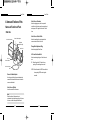
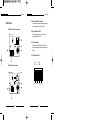
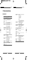
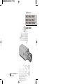
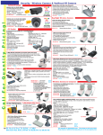
User Guide
CAUTION
RISK OF ELECTRIC
SHOCK, DO NOT OPEN
CAUTION : TO REDUCE THE RISK OF ELECTRIC SHOCK, DO
NOT REMOVE COVER (OR BACK).
NO USER-SERVICEABLE PARTS INSIDE.
REFER SERVICING TO QUALIFIED SERVICE
PERSONNEL.
The lightning flash, with an arrowhead
symbol, within an equilateral triangle, is
intended to alert the user to the presence of
uninsulated “dangerous voltage” within the
product’s enclosure, that may be of sufficient
magnitude to constitute a risk of electric
shock to persons.
The exclamation point within an equilateral
triangle is intended to alert the user to the
presence of important operating and
maintenance (servicing) instruction in the
literature accompanying the appliance.
WARNING : TO PREVENT FIRE OR SHOCK HAZARD, DO
NOT EXPOSE THIS APPLIANCE TO RAIN OR
MOISTURE.
User Guide
1. Read all of these instructions.
2. Save these instruction for later use.
3. Unplug this appliance system from the wall
outlet before cleaning
Do not use liquid cleaners or aerosol cleaner.
Use a damp cloth for cleaning.
4. Do not use attachments not recommended by
the appliance manufacturer, as they may cause
hazards.
5. Do not use this appliance near water for
example, near a bathtub, washbowl, kitchen
sink, laundry tub, in a wet basement, or near a
swimming pool, etc.
6. Do not place this appliance on an unstable cart,
stand, or table.
The appliance may fall causing serious injury to
a child or adult, and serious damage to the
appliance.
Use only with a cart or stand recommended by
the manufacturer’s instructions, and use a
mounting kit approved by the manufacturer.
An appliance and cart combination should be
moved with care. Quick stops, excessive force,
and uneven surfaces may
cause the appliance and cart
combination to overturn.
IMPORTANT SAFEGUARDS
i
ii
User Guide
7. Slots and openings in the cabinet on the back or
bottom are provided for ventilation, to insure
reliable operation of the appliance, and to
protect from overheating.
These openings should never be blocked by
placing the appliance on a bed, sofa, rug or
other similar surfaces. This appliance should
never be placed near or over a radiator or heat
register.
This appliance should not be place in a built-in
installation such as a bookcase, unless proper
ventilation is provided.
8. This appliance should be operated only from
the type of power source indicated on the
marking label. If you are not sure of the type of
power supplied to your home, consult your
dealer or local power company.
9. Do not allow anything to rest on the power
cord. Do not locate this appliance where the
cord will be abused by people walking on it.
10. Do not overload wall outlets and extension
cords, as this can result in fire or electric shock.
11. Follow all warnings and instructions marked on
the appliance.
12. Do not attempt to service this appliance
yourself, as opening or removing covers may
expose you to dangerous voltage or other
hazards. Refer all servicing to qualified service
personnel.
iii
User Guide
13. Unplug this appliance from the wall outlet and
refer servicing to qualified service personnel
under the following conditions:
a. When the power cord or plug is damaged or frayed.
b. If liquid has been spilled into the appliance.
c. If the appliance does not operate normally by
following the operating instructions. Adjust only
those controls that are covered by the operating
instructions, as improper adjustment of other
controls may result in damage and will often
require extensive work by a qualified technician to
restore the appliance to normal operation.
d. If the appliance has been exposed to rain or water.
e. If the appliance has been dropped or the cabinet
has been damaged.
f. When the appliance exhibits a distinct change in
performance this indicates a need for service.
14. When replacement parts are required, be sure
the service technician has used replacement
parts specified by the manufacturer that have
the same characteristics as the original part.
Unauthorized substitutions may result in fire,
electric shock, or other hazards.
15. Upon completion of any service or repairs to
the appliance, ask the service technician to
perform routine safety checks to determine that
the appliance is in safe operating condition.
iv
User Guide
Contents
User Guide
1. Introduction
1. Introduction ............................................ 2
2. Features .................................................. 3
3. Installation .............................................. 4
Precautions in Installation and Use ................... 4
Connecting Auto Iris Lens Connector ................ 5
Mounting Lens .................................................. 6
Setting Lens Selection Switch ........................... 7
Adjusting Back Focus ....................................... 8
Connecting Cable ........................................... 10
4. Names and Functions of Parts ........... 13
Names and Functions of Parts ........................ 13
Function Switches .............................................16
Samsung CCTV B/W Camera (SBC-330A(P)
/331A(P)/300AP/301AP) is a surveillance camera
that employs the latest CCD technology and can be
connected to a CCTV system to provide the best
surveillance capabilities.
Broadcast System
SBC-330A/331A
SBC-330AP/331AP/300AP/301AP
: EIA
: CCIR
Number of CCD pixels
SBC-330A
SBC-331A
SBC-330AP/300AP
SBC-331AP/301AP
: 1/3" 27 megapixel (Normal)
: 1/3" 41 megapixel (Hi-Band)
: 1/3" 32 megapixel (Normal)
: 1/3" 47 megapixel (Hi-Band)
5. Product Specification .......................... 19
Power Supply System
SBC-330A(P)/331A(P)
SBC-300AP/301AP
1
: AC 24V , DC12V
: AC 220V~240V
2
User Guide
2. Features
User Guide
3. Installation
Precautions in Installation and Use
High Sensitivity
Adopting the 1/3" Super HAD CCD that has the
latest built-in microchip lens, the high sensitivity is
realized.
➀ Do not attempt to disassemble the camera
yourself.
② Be cautious in handling the camera. Avoid
Excellent Back Light Compensation
The built-in backlight compensation (BLC) function
provides a clear, sharp image even when monitoring
strongly backlit subjects.
striking or shaking the camera. Be cautious to
avoid damage on the camera caused by improper
storage or operation.
➂ Do not expose this camera to rain or moisture.
Do not operate this camera on a wet place.
Digital Line-lock
➃ Do not use strong or abrasive detergents when
The control and reliability has been enhanced due to
the Full Digital Line Lock, which allows users to
adjust the Line Sync Phase.
cleaning the camera body.
Use a dry cloth to clean the camera.
➄ Keep the camera at a cool place away from the
direct sunlight. Leaving it under the direct
sunlight may result in the malfunction of the unit.
3
4
User Guide
Connecting Auto Iris Lens Connector
Prepare the following Auto Iris Lens Connector
supplied with the camera.
Rib
Pin3
Pin1
User Guide
Mounting the Lens
Loosen a screw fixing the Flange Back Adjustment
Ring by turning it counterclockwise and turn the
Adjustment Ring to the "C" direction
(counterclockwise) until it stops. Failure to do so
may result in a damage caused by the bump of the
lens against the image sensor part in the camera
when mounting the lens.
Pin4
Pin2
C Direction
Connect the cable of the control cable, whose
covering is stripped, to the Auto Iris Lens Connector
as shown below.
Pin Number DC Control Type Video Control Type
1
Damp(-)
Power Source (+9V)
2
Damp(+)
Not used
3
Drive(+)
Video Signal
4
Drive(-)
GND
VID
EO
DC
LEN
S
Auto Iris
Control Cable
5
6
User Guide
Setting Lens Selection Switch
When lens mounting is completed, set the Lens
selection Switch on the rear of the camera
according to the mounted lens type.
When the mounted lens is an Auto Iris Lens of the
DC control type, set the Lens Selection Switch to
"DC". When the mounted lens is an Auto Iris Lens of
the Video control type, set the Lens Selection
Switch to "VIDEO".
User Guide
Adjusting Back Focus
Although the Back Focus of the camera has been
adjusted in the factory before its shipment, the focus
may not be accurate for a certain type of the lens.
In this case, follow the procedures below to adjust
the Back Focus. First, following is how to adjust the
Back Focus of the Fixed Focus Lens.
➀ Lightly loosen the screw fixing the Back Focus
Adjustment Ring using a screwdriver.
② Image a vivid subject (with check patterns) at a
distance of more than 10m away and turn the
Focus Ring to the infinity (∞) position.
➂ Adjust the Back Focus Adjustment Ring to obtain
the clearest image of the subject.
➃ Fasten the screw fixing the Back Focus
Adjustment Ring.
O
VIDE
LENS
DC
7
8
User Guide
The following describes how to adjust the Back
Focus when using a Zoom lens.
➀ Lightly loosen the screw fixing the Back Focus
Adjustment Ring using a screwdriver.
② Image a vivid subject (with check patterns) at a
distance of 3~5m away and adjust the zoom of
the lens to TELE as far as it goes. Then adjust
the Focus Ring of the lens to obtain the clearest
image of the subject.
➂ Adjust the zoom of the lens to WIDE as far as it
User Guide
Connecting Cable
After mounting the lens and setting the Lens
Selection Switch, connect the prepared cable to
each terminal of the camera.
➀ First, connect one end of the BNC cable to the
Video Output Terminal (VIDEO OUT) of the
camera.
② Then connect the other end of the BNC cable to
goes. Then turn the Back Focus Ring of the
camera to obtain the clearest image of the
subject.
the Video Input Terminal of the monitor.
➃ Repeat no. ② & ➂ 2~3 times to exactly coincide
the zoom focus from TELE and with that from
WIDE.
➄ Fasten the screw fixing the Back Focus
Adjustment Ring.
VIDEO LINE
AUDIO LINE
Video A
Video B
Video C
IN
IN
IN
OUT
OUT
A
B
C
IN
OUT
OUT
Video In Terminal on the rear of the monitor
O
VIDE
LENS
DC
EO
VID
LENS
DC
BNC Cable
Note:
Turning the Back Focus Adjustment Ring to the "C" direction
beyond the adjustable range makes a sound at the limit.
9
Video Out Terminal
(VIDEO OUT)
10
User Guide
➂ AC24V/DC12V Power Input Camera.
Connect 2 lines of the power adapter using a
Phillips screwdriver to the Power IN Terminal of
the camera as shown below.
User Guide
AC230V Power Input Camera
Connect the power input cord to the AC 230V
power source.
※ Without the distinction of the polarity, connect to
the AC 24V or AC 12V power source.
EO
VID
DC
EO
VID
S
LEN
DC
AC24V
DC12V
11
12
S
LEN
User Guide
4. Names and Functions of Parts
Names and Functions of Parts
• Side View
User Guide
Auto Iris Lens Connector
Used for supplying power, which is required to
control the iris of the lens, as well as control signal,
video signal, or DC signal to the Auto Iris Control
Lens.
Auto Iris Lens Control Cable
Groove for Mount Adapter
Auto lris Lens Connector
Flange-Back
Adjustment Ring
Auto Iris Lens
Used for transmitting the control signals to the
camera to control the iris of the lens.
Flange-Back Adjustment Ring
Used for adjusting the Back Focus.
VID
EO
DC
ALC Lens Selection Switch
LEN
S
Used when selecting the type of Auto Iris Lens to
use.
DC : Select this switch to DC when Iris Lens
requiring DC control signal is mounted.
ALC Lens
Selection Switch
Auto Iris Lens Control
Cable
Groove for Mount Adapter
VIDEO : Select this switch to VIDEO when Auto Iris
Lens requiring VIDEO control signal is
mounted.
Use this groove for fixing the mount adapter to be
connected to the bracket with screws to mount the
camera on the bracket.
Auto Iris Lens (Option)
Lens to be mounted on the camera
Note
When the surface of the camera lens is
contaminated, wipe the surface gently with a tissue
for lens or a cotton cloth applied with ethanol.
13
14
User Guide
User Guide
➀ Power Connection Terminal
• Rear Panel
Terminal to be connected to the power (adapter)
cable- Connect it to AC 24V or DC 12V.
AC24V/DC12V Power Input Camera
➁ Power Indication LED
While the power is properly supplied to the
camera, the LED is turn on.
③ V-Phase Control
5
6
In the Line Lock mode (SYNC LL), use a tool
such as a screwdriver to adjust the vertical sync
phase.
PWR
AC 24V
DC 12V
VIDEO OUT
④ Function Switches
1
AC230V Power Input Camera
1. L/L
3. ELC
2. BLC
4. AGC
ON
SW1
15
SW2
SW3 SW4
16
User Guide
1) SW1(L/L):
If this switch is set to OFF, the camera will
operate in the internal synchronization mode, and
if the switch is set to ON, the camera will operate
in the line lock mode.
If you are monitoring in the automatic switching
mode with multiple cameras connected to a
sequential switcher, and the cameras are set to
INT (internal synchronization) mode, then picture
rolling or flickering will occur during switching
from one camera to another.
Such picture rolling on the monitor can be
remedied by setting this switch to ON and then
adjusting the vertical sync phase with the
V-Phase Control.
※ When using DC 12V power, set the L/L switch to
OFF.
If the L/L switch is set to ON, the camera will not
operate normally.
2) SW2(BLC):
This switch turns on or off the back light
compensation (BLC) function. When there is a
spotlight or strong light from behind the subject,
the subject may appear dark on the monitor. In
such backlighting conditions, set this switch to
ON for clear viewing.
17
User Guide
3) SW2 (ELC):
Use this switch with the Manual Iris Lens. While
this switch is ON, the speed of the electronic
shutter varies with the brightness of the subject
from 1/60 to 1/100,000 sec for automatically
controlling the brightness of the screen.
However, with the Auto Iris Lens (DC or Video
Control), be sure to switch OFF.
4) SW4(AGC):
This switch turns on or off the automatic gain
control (AGC) function, which is a function that
automatically increases the camera's sensitivity
when ambient light drops below a preset level.
Set this switch to ON to automatically adjust the
"gain".
⑤ DC Iris Level Control
When the ALC Lens Selection Switch is set to
DC, adjust this Iris Level Control using an
adjustment rod such as a screwdriver.
➅ Video Output Terminal
This is a terminal to be connected to the Input
Terminal of the monitor. Through this terminal,
the video signals are output.
18
User Guide
User Guide
5. Product Specifications
SBC-330A/331A
ALC /ELC
Item
DC IRIS LENS
Contents
Product Type
CCTV B/W Camera
Broadcasting
EIA STANDARD SYSTEM
VIDEO LENS
ELC
Electronic SHUTTER IRIS function
System
CCD
1/3” IT type S-HAD CCD
No. of Pixel
330A : 510(H) x 492(V)
331A : 768(H) x 494(V)
Scanning Type
Frequency
INTERNAL : 15,750 HZ(H)
LINE LOCK :15,750 HZ(H)
60 HZ(V)
INTERNAL
LINE LOCK(When AC24V power source is used)
Resolution
Video Output
COMPOSITE VIDEO OUT
Power Source
AC24V±10%(60Hz±0.1Hz)
1V p_p 75 Ω/BNC
DC12V+10%-5%
525 Line, 2:1 Interlace
60 HZ(V)
Syne Type
ALC
Power Consumption
Operating
S/N Ratio
more than 50dB
Min. Object
0.1 Lux F1.2 (50 IRE)
-10℃~+50℃
Temperature
Operating
Humidity
~90%
Size
65(W) x 52(H) x 133(L)mm
Weight
About 420g
Altitude
Below 3000m
(BNC included)
330A : 380TV Lines
331A: 550TV Lines
About 2 Watts
Illumination
19
20
User Guide
User Guide
ALC /ELC
DC IRIS LENS
SBC-330AP/331AP/300AP/301AP
Item
Product Type
Broadcasting
VIDEO LENS
ELC
Contents
Electronic SHUTTER IRIS function
CCTV B/W Camera
CCIR STANDARD SYSTEM
Video Output
COMPOSITE VIDEO OUT
Power Source
300AP/301AP
1V p_p 75 Ω/BNC
System
CCD
1/3” IT type S-HAD CCD
No. of Pixel
330AP/300AP : 500(H) x 582(V)
AC220V~240V±10%(50Hz±0.1Hz)
330AP/331AP
331AP/301AP : 752(H) x 582(V)
Scanning Type
625 Line, 2:1 Interlace
Frequency
INTERNAL : 15,625 HZ(H)
50 HZ(V)
LINE LOCK :15,625 HZ(H)
50 HZ(V)
Syne Type
INTERNAL
LINE LOCK(When AC power source is used)
Resolution
330AP/300AP : 380TV Lines
331AP/301AP: 550TV Lines
S/N Ratio
Min. Object
AC24V±10%(50Hz±0.1Hz)
DC12V+10%-5%
Power Consumption
300AP/301AP: About 3 Watts
330AP/331AP: About 2 Watts
Operating
-10℃~+50℃
Temperature
Operating
Humidity
Size
~90%
65(W) x 52(H) x 133(L)mm
(BNC included)
more than 50dB
0.1 Lux F1.2 (50 IRE)
ALC
Weight
300AP/301AP : About 520g
330AP/331AP : About 420g
Illumination
Altitude
21
Below 3000m
22
Digital B/W Camera
SBC-330A / 330AP
SBC-331A / 331AP
SBC-300AP / 301AP
User Guide
Part No.: AB68-00346A (Rev. 01)
Printed in Korea