1
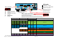
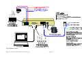
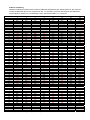
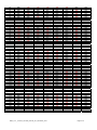
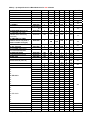
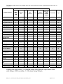
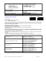
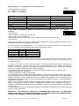
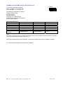
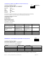
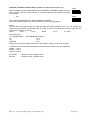
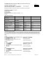
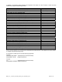
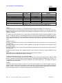
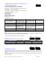
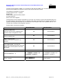
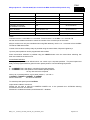
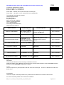
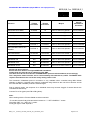
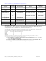
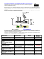
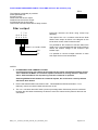
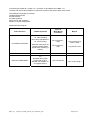
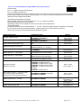
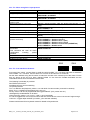
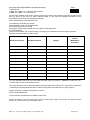
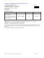
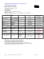
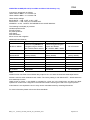
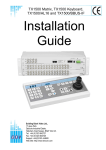
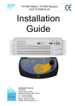
BBV 1-2-1 Protocol Converter
Installation
Guide
BBV single camera protocol converter
Software version CONV3V41
Building Block Video Ltd
17 Apex Park,
Diplocks Industrial Estate,
Hailsham, East Sussex, BN27 3JU, UK
Tel: + 44 (0) 1323 842727
Fax: +44 (0) 1323 842728
www.bbvcctv.com
BBV_1-2-1 _Protocol_converter_manual_V41_November_2013
Page 2 / 40
This manual covers BBV single channel protocol converter
software version CONV3_V41
Table of content.
Compatible Protocols
4
FORWARD VISION MIC1300/400 from BBV
telemetry
20
VCL TP
34
Fig 1 PCB Layout
5
JVC TK-C676 – Fixed at
9600,E,8,1
22
VCL TP – from 360 Vision
Protocol
34
Fig 2 System Layout
6
LG DOME (PELCO D)
from BBV telemetry
22
Vicon Surveyor from BBV
telemetry
35
Address numbering
7
MARK MERCER from
BBV telemetry
23
VIDECON VCP451
CAMERA from BBV
telemetry
36
Output Protocol & Baud
Selection
8
MARK MERCER from
VICON telemetry
23
VIDECON VHSD 860
DOME from BBV telemetry
37
RS232 serial port
11
Meyertech ZVR-510
receiver with VICTA
protocol from BBV
telemetry
24
VIDEOTEC ULISSE
(PELCO D) from BBV
telemetry
38
Supported input and
output protocols
12
Molynx protocol – Fixed
at 9600,E,8,1 Control
from BBV telemetry
25
360 VISION from BBV
telemetry
13
NIO D86/Intercepter
(PELCO D) from BBV
telemetry
26
360 VISION from VCL
telemetry
14
PANASONIC WVCS850/860 from BBV
telemetry
27
15
PELCO P and PELCO D
28
Chugai/Ganz ZCS122/123 – Fixed at
9600,E,8,1
16
Philips RS232/485 from
BBV telemetry
29
CONWAY dome from
BBV telemetry
17
PHOTOSCAN FIXED
SPEED PAN/TILT
from BBV telemetry
30
COP PELCO D or
PELCO P from BBV
telemetry
18
Samsung SCC641/643
dome and SCC421
camera from BBV
telemetry
31
DENNARD 20xx – Fixed
at 9600,N,8,1
18
Sensormatic RS422 from
BBV telemetry
32
DM DTMF RECEIVERS
USING TAD3 from BBV
telemetry
19
VCL TP – Fixed at
9600,N,8,1
33
BBV 422
Chugai SMD20, STAR
MD2000, SANYO
VCC9200P from BBV
telemetry
BBV_1-2-1 _Protocol_converter_manual_V41_November_2013
Vista PowerDome from
BBV telemetry
Page 3 / 40
39
Protocols compatible with the BBV 1-2-1 converter:
360 Vision
BBV 422
CBC SMD20
Chugai
Conway
COP (Pelco D or P)
Dennard 2050
DM DTMT (using TAD3 with special s/w)
Forward Vision Mic1-300/400
Ganz ZC-S122/123
JVC 676
LG dome (Pelco D)
Mark Mercer
Meyertech ZVR510 VICTA protocol
Molynx 250/260
NIO D86/Intercepter (Pelco D)
Panasonic CS850/860
Pelco D
Pelco P
Philips RS232/485 (bi-phase via Philips LTC8780/50)
Photoscan fixed speed pan/tilt
Samsung 641/643 dome 421P camera
Sanyo VCC9200P
Sensormatic RS422 (Ultradome)
Star MD2000
VCL
Vicon Surveyor & V1305DC
Videcon VHSD860 Dome (Pelco P-9600,N,8,1)
Videcon VPC451 Camera (Pelco D-2400,N,8,1)
Videotec Ulisse (Pelco D)
Vista PowerDome
BBV 1-2-1 converter Manual Version History
V41
V39
V38
30 Oct 13
18 April 2013
15 Jun 2012
V37.1
V37
V36.2
V36.1
V36
6 Dec 2011
27 Aug 2011
15 July 2010
15 June 2010
28 May 2010
1. Mark Mercer In to the BBV121 Converter SW3-2,3,4,5,6,7,8 ON
1. All Output protocols now supported from the Pelco D/P Input.
1. Added Dennard RS485 input protocol SW3-6,7,8 ON
2. Added ability to force output protocol address to 1 using SW3-1 as shown on page 5
3. Modified diagrams pages 5 & 6 to show MOLYNX input connection, GREEN pair
4. Document camera 1-16 limitation using Molynx 6000 controller and Molynx In protocol
1.Reformat switch settings page 5 Fig 1, PCB layout
1.Added Molynx D type input telemetry
1.Change text on page 5 SW3 read output and changed BBV485 for BBV422
1.Change text on page 30 to read SW1/3&4 instead of SW3 & SW4
1.Release of the BBV single channel protocol 1-2-1 converter
BBV_1-2-1 _Protocol_converter_manual_V41_November_2013
Page 4 / 40
PROG INK1
BBV
LED guide
SW3
SW2
PCB 02005 Iss 4 SW1
ON
ON
ON
1
2
3
4
5
6
7
1
8
1
2
3
4
5
6
7
2
3
4
5
6
7
GREEN LD1 - data IN
8
8
SW4
SW1 - termination
YELLOW LD2 - data ERROR
ON
ON
1
J3
J7
J4 RS422/485
INPUT
RS232
DEBUG
RS422/485
J1 OUTPUT
2
3
4
5
6
7
RED LD3 - data OUT
8
J6
DATA In Termination
ON
Terminated
3/4
DATA Out Termination
ON
5
Terminated
Not used
6/7
MUST BE ON
8
Not used
LD3
SW4 output protocol.
POWER
1/2
LD2
LD1
1 2 3 4 5 6 7 8
SW2 address selection.
For settings see page 9.
SW3 input protocol
For settings see page 7.
SW3/1 – Output camera address
Off Camera address same as input camera address
ON Output camera address always 1
1 2 3 4 5 6 7 8
This can assist with some installations where existing domes/receivers are
addressed as 1 therefore the dome/receiver doesn’t need to be reconfigured.
2 - 3 Parity
SW3/2 SW3/3 Parity
off off ON
ON
off off ON
ON
off
ON
off
ON
off
ON
off
ON
NONE
EVEN
ODD
NONE
NONE
EVEN
ODD
NONE
off
off
ON
off
ON
off
2400
4800
9600
off
off
ON
off
ON
off
2400
4800
9600
off
ON
SW3/2 SW3/3 ON ON 4 - 5 Baud Rate
SW3/4 SW3/5 Baud
ON
off
SW3/4 SW3/5
ON ON 4800
9600
6 - 8 Protocol Selection SW3/6 SW3/7 SW3/8 off
off
off
off
off
off
Input Protocol
BBV RS422 (TX1500/FBM) (fixed at 9600,N,8,1)
ON
PELCO P
ON
off
PELCO D
off
ON
ON
off
ON
off
VCL TP (fixed at 9600,N,8,1)
360 VISION (fixed at 9600,N,8,1)
ON
off ON
VICON (4800,N,8,1 or 9600,N,8,1) ON
ON
off
ON
ON
SW3/6 SW3/7
ON ON ON
SW3/8 ON MOLYNX “D” TYPE TELEMETRY (fixed at 9600,
E,8,1)
DENNARD (fixed at 9600,N,8,1)
Fig 1 PCB Layout
BBV_1-2-1 _Protocol_converter_manual_V41_November_2013
Page 5 / 40
Mark Mercer (fixed at 9600 N,8,1)
GND
RS232 OUT
RS232 IN
+V OUT
GREEN
BROWN / WHITE
BROWN
BLUE / WHITE
BLUE
GREEN / WHITE
ORANGE
ORANGE / WHITE
BROWN
BROWN / WHITE
GREEN
BLUE / WHITE
GREEN / WHITE
BLUE
Page 6 / 40
BBV_1-2-1 _Protocol_converter_manual_V41_November_2013
ORANGE
ORANGE / WHITE
Fig 2 System Layout
5 nc
4 nc
3 TA/+(OUT)
2 TB/-(OUT)
1 GND
Address numbering
Address numbering is limited to the number of addresses supported by the selected protocol; the maximum
number of addresses that can be supported is 128. For example, a protocol that supports 256 addresses
would support a maximum of 128 addresses when used with the BBV 1-2-1 converter.
Camera
1.
2.
3.
4.
5.
6.
7.
8.
9.
10.
11.
12.
13.
14.
15.
16.
17.
18.
19.
20.
21.
22.
23.
24.
25.
26.
27.
28.
29.
30.
31.
32.
33.
34.
35.
36.
37.
38.
39.
40.
41.
42.
43.
44.
45.
46.
47.
48.
49.
50.
51.
52.
53.
54.
55.
56.
57.
58.
59.
60.
61.
62.
1
SW1
OFF
ON
OFF
ON
OFF
ON
OFF
ON
OFF
ON
OFF
ON
OFF
ON
OFF
ON
OFF
ON
OFF
ON
OFF
ON
OFF
ON
OFF
ON
OFF
ON
OFF
ON
OFF
ON
OFF
ON
OFF
ON
OFF
ON
OFF
ON
OFF
ON
OFF
ON
OFF
ON
OFF
ON
OFF
ON
OFF
ON
OFF
ON
OFF
ON
OFF
ON
OFF
ON
OFF
ON
2
SW2
OFF
OFF
ON
ON
OFF
OFF
ON
ON
OFF
OFF
ON
ON
OFF
OFF
ON
ON
OFF
OFF
ON
ON
OFF
OFF
ON
ON
OFF
OFF
ON
ON
OFF
OFF
ON
ON
OFF
OFF
ON
ON
OFF
OFF
ON
ON
OFF
OFF
ON
ON
OFF
OFF
ON
ON
OFF
OFF
ON
ON
OFF
OFF
ON
ON
OFF
OFF
ON
ON
OFF
OFF
Camera address selection SW2
4
8
16
SW3
SW4
SW5
OFF
OFF
OFF
OFF
OFF
OFF
OFF
OFF
OFF
OFF
OFF
OFF
ON
OFF
OFF
ON
OFF
OFF
ON
OFF
OFF
ON
OFF
OFF
OFF
ON
OFF
OFF
ON
OFF
OFF
ON
OFF
OFF
ON
OFF
ON
ON
OFF
ON
ON
OFF
ON
ON
OFF
ON
ON
OFF
OFF
OFF
ON
OFF
OFF
ON
OFF
OFF
ON
OFF
OFF
ON
ON
OFF
ON
ON
OFF
ON
ON
OFF
ON
ON
OFF
ON
OFF
ON
ON
OFF
ON
ON
OFF
ON
ON
OFF
ON
ON
ON
ON
ON
ON
ON
ON
ON
ON
ON
ON
ON
ON
OFF
OFF
OFF
OFF
OFF
OFF
OFF
OFF
OFF
OFF
OFF
OFF
ON
OFF
OFF
ON
OFF
OFF
ON
OFF
OFF
ON
OFF
OFF
OFF
ON
OFF
OFF
ON
OFF
OFF
ON
OFF
OFF
ON
OFF
ON
ON
OFF
ON
ON
OFF
ON
ON
OFF
ON
ON
OFF
OFF
OFF
ON
OFF
OFF
ON
OFF
OFF
ON
OFF
OFF
ON
ON
OFF
ON
ON
OFF
ON
ON
OFF
ON
ON
OFF
ON
OFF
ON
ON
OFF
ON
ON
OFF
ON
ON
OFF
ON
ON
ON
ON
ON
ON
ON
ON
BBV_1-2-1 _Protocol_converter_manual_V41_November_2013
32
SW6
OFF
OFF
OFF
OFF
OFF
OFF
OFF
OFF
OFF
OFF
OFF
OFF
OFF
OFF
OFF
OFF
OFF
OFF
OFF
OFF
OFF
OFF
OFF
OFF
OFF
OFF
OFF
OFF
OFF
OFF
OFF
OFF
ON
ON
ON
ON
ON
ON
ON
ON
ON
ON
ON
ON
ON
ON
ON
ON
ON
ON
ON
ON
ON
ON
ON
ON
ON
ON
ON
ON
ON
ON
64
SW7
OFF
OFF
OFF
OFF
OFF
OFF
OFF
OFF
OFF
OFF
OFF
OFF
OFF
OFF
OFF
OFF
OFF
OFF
OFF
OFF
OFF
OFF
OFF
OFF
OFF
OFF
OFF
OFF
OFF
OFF
OFF
OFF
OFF
OFF
OFF
OFF
OFF
OFF
OFF
OFF
OFF
OFF
OFF
OFF
OFF
OFF
OFF
OFF
OFF
OFF
OFF
OFF
OFF
OFF
OFF
OFF
OFF
OFF
OFF
OFF
OFF
OFF
Page 7 / 40
128
SW8
OFF
OFF
OFF
OFF
OFF
OFF
OFF
OFF
OFF
OFF
OFF
OFF
OFF
OFF
OFF
OFF
OFF
OFF
OFF
OFF
OFF
OFF
OFF
OFF
OFF
OFF
OFF
OFF
OFF
OFF
OFF
OFF
OFF
OFF
OFF
OFF
OFF
OFF
OFF
OFF
OFF
OFF
OFF
OFF
OFF
OFF
OFF
OFF
OFF
OFF
OFF
OFF
OFF
OFF
OFF
OFF
OFF
OFF
OFF
OFF
OFF
OFF
63.
64.
65.
66.
67.
68.
69.
70.
71.
72.
73.
74.
75.
76.
77.
78.
79.
80.
81.
82.
83.
84.
85.
86.
87.
88.
89.
90.
91.
92.
93.
94.
95.
96.
97.
98.
99.
100.
101.
102.
103.
104.
105.
106.
107.
108.
109.
110.
111.
112.
113.
114.
115.
116.
117.
118.
119.
120.
121.
122.
123.
124.
125.
126.
127.
128.
OFF
ON
OFF
ON
OFF
ON
OFF
ON
OFF
ON
OFF
ON
OFF
ON
OFF
ON
OFF
ON
OFF
ON
OFF
ON
OFF
ON
OFF
ON
OFF
ON
OFF
ON
OFF
ON
OFF
ON
OFF
ON
OFF
ON
OFF
ON
OFF
ON
OFF
ON
OFF
ON
OFF
ON
OFF
ON
OFF
ON
OFF
ON
OFF
ON
OFF
ON
OFF
ON
OFF
ON
OFF
ON
OFF
ON
ON
ON
OFF
OFF
ON
ON
OFF
OFF
ON
ON
OFF
OFF
ON
ON
OFF
OFF
ON
ON
OFF
OFF
ON
ON
OFF
OFF
ON
ON
OFF
OFF
ON
ON
OFF
OFF
ON
ON
OFF
OFF
ON
ON
OFF
OFF
ON
ON
OFF
OFF
ON
ON
OFF
OFF
ON
ON
OFF
OFF
ON
ON
OFF
OFF
ON
ON
OFF
OFF
ON
ON
OFF
OFF
ON
ON
ON
ON
OFF
OFF
OFF
OFF
ON
ON
ON
ON
OFF
OFF
OFF
OFF
ON
ON
ON
ON
OFF
OFF
OFF
OFF
ON
ON
ON
ON
OFF
OFF
OFF
OFF
ON
ON
ON
ON
OFF
OFF
OFF
OFF
ON
ON
ON
ON
OFF
OFF
OFF
OFF
ON
ON
ON
ON
OFF
OFF
OFF
OFF
ON
ON
ON
ON
OFF
OFF
OFF
OFF
ON
ON
ON
ON
ON
ON
OFF
OFF
OFF
OFF
OFF
OFF
OFF
OFF
ON
ON
ON
ON
ON
ON
ON
ON
OFF
OFF
OFF
OFF
OFF
OFF
OFF
OFF
ON
ON
ON
ON
ON
ON
ON
ON
OFF
OFF
OFF
OFF
OFF
OFF
OFF
OFF
ON
ON
ON
ON
ON
ON
ON
ON
OFF
OFF
OFF
OFF
OFF
OFF
OFF
OFF
ON
ON
ON
ON
ON
ON
ON
ON
BBV_1-2-1 _Protocol_converter_manual_V41_November_2013
ON
ON
OFF
OFF
OFF
OFF
OFF
OFF
OFF
OFF
OFF
OFF
OFF
OFF
OFF
OFF
OFF
OFF
ON
ON
ON
ON
ON
ON
ON
ON
ON
ON
ON
ON
ON
ON
ON
ON
OFF
OFF
OFF
OFF
OFF
OFF
OFF
OFF
OFF
OFF
OFF
OFF
OFF
OFF
OFF
OFF
ON
ON
ON
ON
ON
ON
ON
ON
ON
ON
ON
ON
ON
ON
ON
ON
ON
ON
OFF
OFF
OFF
OFF
OFF
OFF
OFF
OFF
OFF
OFF
OFF
OFF
OFF
OFF
OFF
OFF
OFF
OFF
OFF
OFF
OFF
OFF
OFF
OFF
OFF
OFF
OFF
OFF
OFF
OFF
OFF
OFF
ON
ON
ON
ON
ON
ON
ON
ON
ON
ON
ON
ON
ON
ON
ON
ON
ON
ON
ON
ON
ON
ON
ON
ON
ON
ON
ON
ON
ON
ON
ON
ON
OFF
OFF
ON
ON
ON
ON
ON
ON
ON
ON
ON
ON
ON
ON
ON
ON
ON
ON
ON
ON
ON
ON
ON
ON
ON
ON
ON
ON
ON
ON
ON
ON
ON
ON
ON
ON
ON
ON
ON
ON
ON
ON
ON
ON
ON
ON
ON
ON
ON
ON
ON
ON
ON
ON
ON
ON
ON
ON
ON
ON
ON
ON
ON
ON
ON
ON
Page 8 / 40
OFF
OFF
OFF
OFF
OFF
OFF
OFF
OFF
OFF
OFF
OFF
OFF
OFF
OFF
OFF
OFF
OFF
OFF
OFF
OFF
OFF
OFF
OFF
OFF
OFF
OFF
OFF
OFF
OFF
OFF
OFF
OFF
OFF
OFF
OFF
OFF
OFF
OFF
OFF
OFF
OFF
OFF
OFF
OFF
OFF
OFF
OFF
OFF
OFF
OFF
OFF
OFF
OFF
OFF
OFF
OFF
OFF
OFF
OFF
OFF
OFF
OFF
OFF
OFF
OFF
OFF
SW4 (1 - 6) Output Protocol & Baud Selection for V41 software
PROTOCOL
1.SELF TEST
2.DEBUG MODE
3.360 VISION
4.BBV RS422
6.CHUGAI SMD20
7.CHUGAI ZC- S122
8.CONWAY
9.COP DOME (PELCO P/D)
10.DENNARD 20xx series
11. DM DTMF via TAD3
(Camera select sent every
command)
12. DM DTMF via TAD3
(Camera select only sent if
camera number changed)
13.FORWARD VISION
14.JVC TK-C676
15.LG DOME (PELCO D)
LPT-OI551HQ/OI553HQ
16.MARK MERCER
17.MEYERTECH VICTA
18.MOLYNX
19. NIO/DYNAPEL
INTERCEPTER (Pelco D)
20.PANASONIC 850
21.PANASONIC 850
22.
23.
24.
25.
26. PELCO P
27.
28.
29.
30.
31.
32.
33.
34.
35. PELCO D
36.
37.
38.
39.
40.PHILIPS RS232
41.PHOTOSCAN
42.SAMSUNG SCC641/643
43.SENSORMATIC RS422
BAUD
9600 N 8 1
19200 N 8 1
9600 N 8 1
9600 N 8 1
9600 N 8 1
9600 E 8 1
9600 N 8 1
2400/9600 N
81
9600 N 8 1
1
2
3
4
5
6
PAGE
off
off
off
Off
off
off
ON
off
off
Off
off
off
off
ON
ON
ON
ON
off
ON
ON
ON
ON
ON
ON
Off
off
off
off
off
off
off
ON
ON
off
off
ON
ON
ON
ON
off
off
ON
11
14
15
15
16
17
off
ON
ON
off
off
ON
18
off
ON
off
Off
off
off
18
9600 N 8 1
ON
off
ON
ON
off
ON
19
9600 N 8 1
off
ON
ON
ON
off
ON
19
9600 O 8 1
9600 E 8 1
ON
ON
ON
off
off
ON
off
off
off
ON
off
off
20
22
9600 N 8 1
ON
off
off
ON
off
ON
22
9600 N 8 1
9600 N 8 1
9600 E 8 1
ON
ON
ON
ON
ON
off
Off
off
off
off
off
off
ON
ON
off
ON
off
off
23
24
25
9600 N 8 1
off
off
off
off
ON
ON
26
ON
off
Off
off
off
off
ON
Off
off
off
ON
ON
ON
ON
off
off
off
off
off
off
off
off
Off
off
ON
ON
ON
ON
9600 N 8 1
19200 N 8 1
9600 N 8 1
9600 O 8 1
9600 E 8 1
4800 N 8 1
4800 O 8 1
4800 E 8 1
2400 N 8 1
2400 O 8 1
2400 E 8 1
9600 N 8 1
9600 O 8 1
9600 E 8 1
4800 N 8 1
4800 O 8 1
4800 E 8 1
2400 N 8 1
2400 O 8 1
2400 E 8 1
9600 N 8 1
2400 E 8 1
9600 N 8 1
4800 N 8 1
off
off
ON
off
off
ON
ON
ON
ON
ON
ON
ON
ON
ON
off
off
off
ON
off
off
Off
off
off
Off
ON
ON
ON
off
Off
off
off
Off
ON
off
off
ON
ON
ON
ON
ON
ON
ON
off
off
off
ON
off
off
off
ON
ON
off
ON
ON
ON
ON
ON
ON
ON
ON
ON
ON
ON
ON
ON
ON
ON
ON
ON
ON
ON
ON
ON
ON
ON
ON
off
off
off
off
ON
off
off
off
off
off
off
off
off
off
off
ON
off
off
ON
off
off
off
ON
off
ON
off
off
BBV_1-2-1 _Protocol_converter_manual_V41_November_2013
27
off
off
off
off
28
off
off
off
off
off
off
off
off
off
29
30
31
32
Page 9 / 40
44.VCL
45.VICON
47.VIDECON VCP451
46.VIDECON VHSD860
48.Videotec Ulisse(Pelco D)
49.VISTA POWERDOME
9600 N 8 1
4800/9600 N
81
2400 N 8 1
9600 N 8 1
9600 N 8 1
9600 N 8 1
off
off
ON
Off
off
off
34
off
off
off
off
off
ON
35
off
off
ON
off
ON
ON
ON
ON
ON
off
off
ON
ON
ON
ON
off
off
off
off
ON
ON
ON
ON
36
37
38
39
off
FORMAT OF BAUD SETTINGS, BAUD RATE PARITY (NONE, EVEN, ODD) DATABITS STOPBITS
STOP AND READ BEFORE INSTALLING!
AS 3RD PARTY PROTOCOLS ARE NOT UNDER THE
CONTROL OF BBV, WE CANNOT GUARANTEE THAT
THIS
UNIT
WILL
PROVIDE
THE
EXACT
FUNCTIONALITY REQUIRED.
IT IS STRONGLY RECOMMENDED THAT OPERATION
IS CONFIRMED DURING PRE BUILD TESTING BEFORE
INSTALLING ON SITE.
PLEASE CONTACT OUR CUSTOMER SUPPORT
DEPARTMENT IF YOU HAVE ANY QUESTIONS/ISSUES:
Tel: ++ 44 (0) 1323 444600
Email: [email protected]
BBV_1-2-1 _Protocol_converter_manual_V41_November_2013
Page 10 / 40
RS232 serial port
The DB9F connector provides the ability to use a laptop PC to monitor the data being sent out of the BBV
1-2-1 converter via RS232.
On power up or if SW2, SW3 or SW4 switches are altered the unit sends the current protocol, baud rate
and parity settings. Please be aware that the laptop baud rate and parity must match the settings selected
with SW4. If the settings do not match then the laptop display will have no meaning.
A power up message example is shown below:
BBV 1-2-1 converter conv3V39
www.bbvcctv.com
SW2(ADDR) = 01
SW3(IN) = 10 BBV:9600,N,8,1
SW4(OUT) = A3 MARK MERCER V7.3:9600,N,8,1
A debug mode can also be selected which provides detailed information for each command received.
Whilst trouble shooting BBV engineers may ask you to use this mode with a laptop or other PC:
BBV 1-2-1 converter conv3V39
www.bbvcctv.com
SW2(ADDR) = 01
SW3(IN) = 10 BBV:9600,N,8,1
SW4 (OUT) = 01 DEBUG MODE:19200,N,8,1
CAM=00 W3=00 W4=14 W5=40 W6=24 PL 064TD 036
CAM=00 W3=00 W4=14 W5=06 W6=3C PL 006TD 060
CAM=00 W3=00 W4=12 W5=2E W6=38 PR 046TD 056
CAM=00 W3=00 W4=12 W5=40 W6=08 PR 064TD 008
CAM=00 W3=00 W4=08 W5=00 W6=0C TU 012
CAM=00 W3=00 W4=04 W5=40 W6=00 PL 064
CAM=00 W3=00 W4=14 W5=32 W6=34 PL 050TD 052
CAM=00 W3=00 W4=12 W5=2A W6=38 PR 042TD 056
CAM=00 W3=00 W4=04 W5=36 W6=00 PL 054
CAM=00 W3=00 W4=00 W5=00 W6=00 Cam 00 stop
The example above shows the debug output for Camera 1. Driving pan/tilt followed by a stop command.
BBV_1-2-1 _Protocol_converter_manual_V41_November_2013
Page 11 / 40
The following table shows the possible input and output protocols that are supported with this version of
software.
Input Protocol
MOLYNX
USE
GREEN
PAIR
BBV
TX1500
FBM
PELCO
D/P
VCL
360 VISION
X
X
X
BBV RS422
X
X
Chugai SMD20
X
X
15
Chugai ZCS122/123
X
X
16
CONWAY DOME
X
X
17
COP (PELCO D)
X
X
18
DENNARD 2050
X
X
DM DTMF VIA TAD3
X
X
19
FORWARD VISION
X
X
20-21
JVC TKC676
X
X
LG DOME PELCO D
X
X
MARK MERCER
MEYERTECH
VICTA
MOLYNX 250/260
NIO D86
INTERCEPTER
PANASONIC
CS850/860
PELCO D/P
X
X
X
X
24
X
X
25
X
X
26
X
X
X
X
X
27
X
X
X
X
X
28
PHILIPS RS232
X
X
X
X
X
29
PHOTOSCAN
SAMSUNG
SCC641/643
SENSORMATIC
RS422
VCL TP
X
X
30
X
X
31
X
X
X
X
VICON
X
X
VIDECON VCP451
VIDECON VHSD
860
VIDEOTEC ULISSE
VISTA
POWERDOME
X
X
X
X
X
X
X
X
Output Protocol
360
VISION
VICON
MARK
MERCER
DENNARD
Page
13
X
X
X
X
X
X
X
X
X
15
18
22
22
X
X
X
X
X
X
X
X
32
X
X
X
33-34
X
X
X
34
36
X
X
X
37
38
X
X
X
Please note the limited 1-16 camera range using Molynx input when used
with Molynx 6000 controller. 1-128 when using Visilynx.
BBV_1-2-1 _Protocol_converter_manual_V41_November_2013
23
Page 12 / 40
39
Protocol specific information
SW4
360 VISION from BBV
Connect dome D+ to BBV 1-2-1 converter TA
and dome D- to BBV 1-2-1 converter TB.
Set the dome address using the DIL switch to match the number of
the camera input of the TX1500.
Ensure that the dome at the end of a daisy chained RS485 run has the RS485 terminated and the
intermediate domes have the RS485 de-terminated.
The following functionality is provided:
Manual pan/tilt control with 16 speed steps from 1 to 127, (slowest to fastest)
Zoom with Manual Iris and Focus override.
Operating the Zoom will re-enable auto focus and iris after manual adjustment
32 preset positions.
2 sequential preset tours of preset positions 1 - 16, tour 1 high speed and tour 2 slow speed. The dwell time
is fixed at 10 seconds per preset position. Preset positions can be removed from the tours.
All 32 privacy zones can be programmed and disabled if required.
Advanced Function
180 degree pan flip (U turn)
Program a privacy zone
Clear a privacy zone
Add preset position to the tours
Remove a preset from the tours
Start preset tour 1 – high speed
Start preset tour 2 – slow speed
Set autoflip mode
Set Video Gain/Lift and Sync timing
Set IR Filter mode
Set Home functions
(Revised in V16 software)
Unit Reset.
This simulates powering the dome off/on
Preset Tour Definition
Example to program tour 1
Step 1 – define tour. PROGRAM 56 PRESET
Step 2 – tour 1 or 2. 1 PRESET
Step 3 – 4 presets for each preset point
1 PRESET (point 1)
1 PRESET (PRESET 1)
64 PRESET (max speed)
10 PRESET (10 seconds dwell)
BBV_1-2-1 _Protocol_converter_manual_V41_November_2013
TX1500 Procedure
1#
2 # followed by
PROGRAM 1-32 PRESET
3 # followed by
PROGRAM 1-32 PRESET
Programming a preset position adds the preset into
the tour. (1 – 16 only)
PROGRAM 50 PRESET followed by
1-16 PRESET
1 PATROL (max speed with 10 second dwell)
2 PATROL (speed 32 with 10 second dwell)
PROGRAM 51 PRESET followed by
1 PRESET = autoflip OFF
2 PRESET = ON tilt at down limit
3 PRESET = ON when at limit
PROGRAM 52 PRESET followed by
IRIS CLOSE/OPEN to increase/decrease GAIN
FOCUS NEAR/FAR to increase/decrease LIFT
ZOOM IN/OUT to advance/retard timing
Move joystick when finished.
PROGRAM 53 PRESET followed by
1 PRESET = mono mode/auto off
2 PRESET = colour mode/auto off
3 PRESET = auto/kill colour
4 PRESET = auto/don’t kill colour
PROGRAM 54 PRESET followed by
1-5 PRESET = Function
(1=enable,2=disable,3=preset 1,4=tour1,5=mimic 1)
1-60 PRESET = timeout in minutes
PROGRAM 55 PRESET followed by
PROGRAM 55 PRESET
PROGRAM 56 PRESET (start definition)
1 or 2 PRESET – Tour number
1 – 64 PRESET (tour point number)
1 – 32 PRESET (preset number)
1 – 64 PRESET (speed)
1 – 64 PRESET (dwell in seconds
repeated for each point apart from last
Page 13 / 40
Repeat step 3 for each point until the last point
Step 4 – last tour point. PROGRAM 57 PRESET
3 PRESET (point 3)
4 PRESET (PRESET 4)
32 PRESET (middle speed)
2 PRESET (2 seconds dwell)
PROGRAM 57 PRESET (last point)
1 – 64 PRESET (tour point number)
1 – 32 PRESET (preset number)
1 – 64 PRESET (speed)
1 – 64 PRESET (dwell in seconds
The tour is now defined
Mimic Tour Definition
(AUTOPAN will replay the mimic tour)
Fast Shutter ON (ANPR mode)
Fast Shutter OFF (normal mode)
PROGRAM 58 PRESET (start definition)
Use joystick and zoon to move dome around
required tour.
PROGRAM 59 PRESET (end definition)
PROGRAM 60 PRESET
PROGRAM 61 PRESET
SW3
360 VISION from VCL telemetry
Connect dome
D+ to 1-2-1 BBV Converter TA and dome
D- to 1-2-1 BBV Converter TB.
SW4
ON
ON
1 2 3 4 5 6 7 8
1 2 3 4 5 6 7 8
Set the dome address using the DIL switch to match the number of the camera input of the TX1500. Ensure
that the dome at the end of a daisy chained RS485 run has the RS485 terminated and the intermediate
domes have the RS485 de-terminated.
The following functionality is provided:
Manual pan/tilt control with 16 speed steps from 1 to 127 (slowest to fastest)
Zoom with Manual Iris and Focus override.
Operating the Zoom will re-enable auto focus and iris after manual adjustment
32 preset positions.
Preset 100 – 127 will program the dome privacy zone 1 – 27. These can be disabled within the VCL privacy
menu by setting the appropriate preset to PRESET. The dome will move to show the privacy scene to allow
toggling the privacy back on by selecting PRIVATE.
Tour definitions are compatible with the VCL programming method 2 including dwell time and speed per
tour point.
The dome home feature can be programmed using the standard VCL control menu.
In addition to the standard functions offered by the VCL control system the following features are available:
Set autoflip mode
Set Video Gain/Lift and Sync timing
Set IR Filter mode
Set Home functions
(fixed at 5 minutes)
Unit Reset.
BBV_1-2-1 _Protocol_converter_manual_V41_November_2013
program preset 51 followed by
goto preset 1 = autoflip OFF
goto preset 2 = ON tilt at down limit
goto preset 3 = ON when at limit
program preset 52 followed by
iris close/open to increase/decrease GAIN
focus near/far to increase/decrease LIFT
zoom in/out to advance/retard timing
Move joystick when finished.
program preset 53 followed by
goto preset 1 = mono mode/auto off
goto preset 2 = colour mode/auto off
goto preset 3 = auto/kill colour
goto preset 4 = auto/don’t kill colour
program preset 54 followed by
goto preset 1 = Enable to preset 1
goto preset 2 = Enable to patrol 1 (fast)
goto preset 3 = Enable to patrol 2 (slow)
goto preset 4 = Disable home
program preset 55 twice
Page 14 / 40
BBV 422 (9600, N, 8, 1) (adjust SW3 to suit input protocol)
SW4
Connect twisted pair as follows:RA + to BBV 1-2-1 convert TA.
RA – to BBV 1-2-1 convert TB.
BBV Function
#1
#2
#3
#4
Patrol 1
Patrol 2
Autopan
Molynx
Cam on then Goto Preset 1
Cam on then Goto Preset 2
Cam on then Goto Preset 3
Cam on then Goto Preset 4
Cam on then Goto Preset 5
Cam on then Goto Preset 6
Cam on then Goto Preset 7
Pelco & Mark Mercer Procedure
Go to Preset 61
Go to Preset 62
Go to Preset 63
Go to Preset 64
Go to Preset 66
Go to Preset 67
Go to Preset 68
Chugai SMD20, STAR MD2000, SANYO VCC9200P from BBV and Pelco D/P
telemetry.
SW4
Connect dome
DATA+ to BBV 1-2-1 Converter TA and dome
DATA- to BBV 1-2-1 Converter TB.
Set the dome address using the DIL switch to match the number of the camera input
of the TX1500.
Ensure that the dome at the end of a daisy chained RS485 run has the RS485 terminated and the
intermediate domes have the RS485 de-terminated.
This type of dome can be addressed from 1 – 31. To allow use of more that 31 domes on a TX1500 system
the 1-2-1 converter can be adjusted to select banks of cameras as follows:
Camera Range
1 - 31
32 - 62
63 - 93
94 - 124
SW4/7
OFF
ON
OFF
ON
SW4/8
OFF (Default setting)
OFF
ON
ON
When the 1-2-1 converter is set for camera range 32 – 62, the dome connected into video input 32 must
have the address set for 1 and video input 33 must have the address set to 2 etc up to video input 62 with
the address set to 31.
i). Timing to the dome is critical, due to the nature of the dome protocol (half duplex command and
response commands). The dome will ignore any command sent before it has finished executing the
previous command; for example, a goto preset command sent whilst the dome is searching for another
preset, (e.g. multiple alarm occurrences in quick succession).
ii) Supported manual PTZ with manual focus which reverts back to auto focus on a pan/tilt or zoom.
iii) 64 preset positions are supported
iv) The AUTOPAN key is used to start patrol 2.
v) 2 preset patrols are provided and the preset positions in each patrol are programmable. Patrol 1 has a
fixed full speed movement to each preset and a dwell of 10 seconds. To define patrol 1, first PROGRAM 65
PRESET, followed by GOTO preset for each of the presets to be patrolled. Up to 64 presets can be
programmed. Each preset position must be programmed prior to defining the patrol. To end the definition
PROGRAM 66 PRESET.
Patrol 2 has a fixed slow speed movement between preset positions and a 10 second dwell at each
position. Programming is similar to Patrol 1. PROGRAM 67 PRESET to start definition, goto preset …
followed by PROGRAM 68 PRESET to end the definition. Patrol 2 can also be started by pressing the
AUTOPAN key.
vi) LEDS, LD2 flashes when commands are received for domes that lie outside of the 31 camera range set
by SW2, SW4/7 and SW4/8.
IMPORTANT: THE DOME WILL IGNORE ALL COMMANDS SENT FROM THE 1-2-1 CONVERTER
WHEN IT IS MOVING TO A PRESET POSITION UNTIL THE PRESET POSITION HAS BEEN REACHED.
THIS RELATES TO MANUAL PRESET OR DURING A PATROL.
BBV_1-2-1 _Protocol_converter_manual_V41_November_2013
Page 15 / 40
Chugai/Ganz ZC-S122/123 – Fixed at 9600,E,8,1 from BBV and Pelco D/P
telemetry only
Function
Menu ON/OFF
SET (whilst in menu)
CLR (whilst in menu)
TX1500 Procedure
1#
2#
3#
Pelco Procedure
Go to Preset 61
Go to Preset 62
Go to Preset 63
PRESET SEQUENCE
PLAYBACK TRACE
AUTOPAN
1 PATROL
2 PATROL
AUTOPAN
Go to Preset 66
Go to Preset 67
Go to Preset 68
AUX 1 OUTPUT ON/OFF
AUX 2 OUTPUT ON/OFF
LIGHTS
WIPER
1 AUX
2 AUX
SW4
Notes:
Connect dome A/+ (pin 1, BROWN) to the BBV 1-2-1 converter TA and dome B/- to the BBV 1-2-1
converter TB.
Each dome must be set to 9600 Baud with switch 5 OFF, switch 6 ON. Set the dome address using the
dome rotary switches to match the number of the camera input of the TX1500. Ensure that domes at the
end of the RS485 run are terminated by turning switch 8 ON and the intermediate domes have the switch 8
OFF.
A total of up to 96 domes are supported with a maximum of 32 domes per star output.
Menu access:
Press 1# will toggle the Menu display ON/OFF.
Whilst the menu is displayed the joystick is used to navigate.
2# is used as SET to access a menu option and
3# is used as CLR to go back.
Addition functions are available for the currently displayed dome:
AUTOPAN is started by pressing the AUTOPAN key.
PRESET SEQUENCE is started by pressing 1 PATROL.
TRACE playback is started by preceding 2 PATROL
The protocol 1-2-1 converter can directly access preset 1 – 64 by pressing the preset number followed by
the PRESET key.
To program a preset position, press PROGRAM followed by the preset number and the PRESET key. See
the TX1500 manual for detailed information.
BBV_1-2-1 _Protocol_converter_manual_V41_November_2013
Page 16 / 40
CONWAY dome from BBV and Pelco D/P telemetry only
SW4
Connect the twisted pair as follows:
Dome A to BBV 1-2-1 converter TB
Dome B to BBV 1-2-1 converter TA
The following functionality is provided:
Variable speed Pan/Tilt
Zoom/Focus/Iris
64 preset positions
Preset tour 1 & 2 playback only
Wash/WIPE/LIGHTS (IR Filer ON/OFF)
Privacy enable, disable
Additional dome features
Dome Function
ENABLE PRIVACY
DISABLE PRIAVCY
Tx1000 Keystroke
hold # and tap WASH
hold # and tap AUTOPAN
TX1500 Keystroke
2#
3#
Pelco Procedure
Go to Preset 62
Go to Preset 63
TOUR 1 PLAYBACK
TOUR 2 PLAYBACK
hold PATROL and tap 1
hold PATROL and tap 2
1 PATROL
2 PATROL
Go to Preset 66
Go to Preset 67
IR CUT FILTER
ON/OFF
LIGHTS ON/OFF
LIGHTS ON/OFF
1 AUX
Note:
The Data connections A/B are crossed when using this dome so please connect the dome A to green
connector TB and dome B to green connector TA.
Preset tours programming is NOT supported. These must be defined first using a CONWAY controller.
For more information please refer to the dome handbook.
BBV_1-2-1 _Protocol_converter_manual_V41_November_2013
Page 17 / 40
COP PELCO D or PELCO P from BBV and Pelco D/P telemetry only
Connect the twisted pair as follows:
dome RS485+ (ORANGE) to BBV 1-2-1 converter TA
dome RS485- (YELLOW) to BBV 1-2-1 converter TB
Baud Rate
2400
9600
Protocol
PELCO D
PELCO P
SW4
SW4/7 Baud
SW4/8 Protocol
SW4/7
OFF (default)
ON
SW4/8
OFF (default)
ON
Set the dome for protocol and baud rate. The default is 2400 baud and Pelco D telemetry.
Set the dome address to match the number of the camera input of the matrix.
The following functionality is provided:
Variable speed Pan/Tilt
Zoom/Focus/Iris
63 preset positions.
Menu access and navigation
Pattern record and playback+
Preset patrol 1 and 2 playback
Additional Dome features
Dome Function
DISPLAY DOME MENU
PATTERN RECORD
START
PATTERN RECORD STOP
PATTERN PLAYBACK
PATROL 1 PLAYBACK
PATROL 2 PLAYBACK
TX1000 Keystroke
hold # and tap WASH
and navigate using the
joystick and IRIS keys
hold # and tap
AUTOPAN then use
joystick to move dome
around required scenes.
hold # and tap LIGHTS
AUTOPAN
hold PATROL and tap 1
hold PATROL and tap 2
TX1500 Keystroke
1 # and navigate
using the joystick
and IRIS keys
3 # then use joystick
to move dome
around the required
scenes.
4#
AUTOPAN
1 PATROL
2 PATROL
DENNARD 20xx – Fixed at 9600,N,8,1 (adjust SW3 to suit input protocol)
Pelco Procedure
Go to Preset 61
Go to Preset 63
Go to Preset 64
Go to Preset 68
Go to Preset 66
Go to Preset 67
SW4
Connect the twisted pair as follows:
dome RS485+ (YELLOW) to BBV 1-2-1 converter TA
dome RS485- (GREEN) to BBV 1-2-1 converter TB
To enter when in menu send a ‘GOTO PRESET 1’
Function
TX1500 Procedure
Display Dome Menu
Display User Menu
Display Technicians Menu
Start current dome’s Sequence 001
Start ALL DOMES Sequence 001
1#
2#
3#
1 PATROL
2 PATROL
Pelco & Mark
Mercer Procedure
Go to Preset 61
Go to Preset 62
Go to Preset 63
Go to Preset 66
Go to Preset 67
Molynx
Cam on then Prog preset 1
Cam on then Prog preset 2
Cam on then Prog preset 3
Cam on then Goto preset 5
Cam on then Goto preset 6
Navigate through the dome menu using pan/tilt and issue GOTO PRESET 1 to select current line.
BBV_1-2-1 _Protocol_converter_manual_V41_November_2013
Page 18 / 40
DM DTMF RECEIVERS USING TAD3 from BBV and Pelco D/P telemetry only.
SW4
SEND CAMERA SELECTS BEFORE EVERY MOVEMENT COMMAND (useful for noisy
links to ensure that the correct camera is controlled although this provides increased
control delay)
SW4
- OR ONLY SEND CAMERA SELECT WHEN CAMERA CHANGES
(This is the normal method and gives improved control for most applications)
Notes
The DM TAD3 must be sourced from DM and fitted with special software TTT1_0 in IC3 position and
ensure that the following configuration links are fitted. If the link is multi pins then only fit links that are
shown and not fitted if not shown
J2/5-6
J4/1-2
J5/2-3
J6/2-3
J7/1-2
J9 – fitted
Connect from the
1-2-1 CONVERTER
TAD3 CBUS DIN SOCKET
TA
pin 2
TB
pin 1
GROUND
pin 3
DTMF from the TAD3 to DTMF receivers use the TONE or AUDIO connector as required.
In addition to the normal manual pan/tilt/zoom commands the following are also supported.
WASH = AUX 1
WIPER = AUX 2
LIGHTS = AUX 3
AUTOPAN
PATROL
= *858001 START, *858000 STOP
= *854001 START, *854000 STOP
BBV_1-2-1 _Protocol_converter_manual_V41_November_2013
Page 19 / 40
FORWARD VISION MIC-1300/400 from BBV and Pelco D/P telemetry only
Connect the twisted pair as follows:
Dome RX A (YELLOW) to BBV 1-2-1 converter TB
Dome RX B (WHITE) to BBV 1-2-1 converter TA
SW4
(A & B swapped)
Set the dome address to match the number of the camera input of the matrix.
The following functionality is provided:
Variable speed Pan/Tilt
Zoom/Focus/Iris
64 preset positions.
Patrol (sequence) record. 8 positions of presets 1 – 16
Autopan
Additional dome features
Dome Function
SPECIAL PROGRAMMING
(see below)
DIGITAL ZOOM ON/OFF
MANUAL/AUTO
EXPOSURE
IR FILTER IN/OUT
ENABLE ALL SCENE
DISABLE ALL SCENE
TOGGLE CURSOR
ON/OFF
ENABLE AROUND
CURSOR
DISABLE AROUND
CURSOR
TX1000 Keystroke
TX1500 Keystroke
hold # and tap WASH
1#
hold # and tap WIPE
hold # and tap
AUTOPAN
hold # and tap LIGHTS
Hold # and tap WASH,
PROGRAM 1, 1
Hold # and tap WASH,
PROGRAM 1, 2
Hold # and tap WASH,
PROGRAM 1, 3
Hold # and tap WASH,
PROGRAM 1, 4
Hold # and tap WASH,
PROGRAM 1, 5
2 #.
3#
4#
1 # PROGRAM 1
PRESET
1 # PROGRAM 2
PRESET
1 # PROGRAM 3
PRESET
1 # PROGRAM 4
PRESET
1 # PROGRAM 5
PRESET
Pelco Procedure
Go to Preset 61
Go to Preset 62
Go to Preset 63
Go to Preset 64
Go to Preset 61, Program 1
Preset
Go to Preset 61, Program 2
Preset
Go to Preset 61, Program 3
Preset
Go to Preset 61, Program 4
Preset
Go to Preset 61, Program 5
Preset
PROGRAM PRESET PATROL
The 1-2-1 CONVERTER supports a single preset patrol per dome with a programmable dwell time and up
to 8 preset positions. Please ensure that you program the preset positions first using the normal procedure.
The keystrokes used will depend on the controller used. The TX1000 and TX1500 procedures are shown
below.
TX1000
a. Hold # and tap WASH, then Hold PATROL and tap 1
b. Hold PRESET and tap 1 – 16
c. Hold PRESET and tap 1 – 16
d. repeat step C for up to 8 preset positions total
e. Hold PATROL and tap 1
TX1500
a. 1 # then 1 PATROL
b. 1 – 64 PRESET
c. 1 – 64 PRESET
d. repeat step C for up to 8 preset positions in total
e. 1 PATROL
Pelco
a. 61 Preset then 66 Preset
b. 1 – 64 PRESET
c. 1 – 64 PRESET
d. repeat step C for up to 8 preset positions in total
e. 66 Preset
(patrol programming mode)
(dwell time 1 – 16 seconds)
(first preset position)
(save the dome patrol)
(patrol programming mode)
(dwell time 1 – 64 seconds)
(first preset position)
(save the dome patrol)
(patrol programming mode)
(dwell time 1 – 64 seconds)
(first preset position)
(save the dome patrol)
Continued on page 21
BBV_1-2-1 _Protocol_converter_manual_V41_November_2013
Page 20 / 40
In addition, the following dome features are supported. First either 1# from TX1500 or Hold # and tap
WASH then program the following presets:
FUNCTION
PAN REVERSE ON/OFF (PRESET 194/195)
AUTO IR ON/OFF (PRESET 196/197)
INTERMITANT WIPE ON/OFF (PRESET 198/199)
SOFTLIMIT TOP LEFT (PRESET 200)
SOFTLIMIT BOTTOM RIGHT (PRESET 201)
NONE DWELL TOP LEFT (PRESET 202)
NONE DWELL BOTTOM RIGHT (PRESET 203)
AUTOHOME PRESET 1 (PRESET 204)
AUTOHOME SEQUENCE (PATROL) (PRESET 205)
AUTOHOME OFF (PRESET 206)
MULTI ALARM ON/OFF (PRESET 207/208)
DIGITAL ZOOM ENABLE/DISABLE (PRESET 209/210)
SET TOUR1,2,3,4,5,6 (PRESET 211-216)
AUTOFLIP ON/OFF (PRESET 217/218)
WASHWIPE ON/OFF (PRESET 219/220)
PRIVACY SET CURSOR (PRESET 221)
PRIVACY INIT PARAMETER (PRESET 222)
PRIVACY LOAD PARAMETER (PRESET 223)
PRIVACY SAVE PARAMETER (PRESET 224)
PRIVACY HIDE CURSOR (PRESET 225)
PRIVACY SHOW CURSOR (PRESET 226)
PRIVACY CLEAR CENTRAL (PRESET 227)
PRIVACY SET CENTRAL (PRESET 228)
PRIVACY SET STYLE (PRESET 229)
PRIVACY HIDE STYLE (PRESET 230)
PRIVACY SHOW STYLE (PRESET 231)
PRIVACY REPLACE ALL (PRESET 232)
PRIVACY UNCOVER ALL (PRESET 233)
PRIVACY CLEAR WHOLE (PRESET 234)
PRIVACY SET WHOLE (PRESET 235)
AUTO ALARM ON/OFF (PRESET 236/237)
AUTO LOWLIGHT ON/OFF (PRESET 238/239)
CAMERA RECALIBRATE (PRESET 251)
RESET PRESETS (PRESET 255)
PROGRAM PRESET
6 ON, 7 OFF
8 ON, 9 OFF
10 ON, 11 OFF
12
13
14
15
16
17
18
19 ON, 20 OFF
21 ON, 22 OFF
23 – 28
29 ON, 30 OFF
31 ON, 32 OFF
33
34
35
36
37
38
39
40
41
42
43
44
45
46
47
48 ON, 49 OFF
50 ON, 51 OFF)
52
53
As the TX1000 supports up to preset 16 all commands that require preset 17 and higher can’t be accessed.
A TX1500 must be used in this case.
For example to enable auto IR use the following keystrokes
TX1000
Hold # and tap WASH (extended dome command mode)
PROGRAM 1 then 8
(program preset 8)
TX1500
1#
(extended dome command mode)
PROGRAM 8 PRESET (program preset 8)
BBV_1-2-1 _Protocol_converter_manual_V41_November_2013
Page 21 / 40
JVC TK-C676 – Fixed at 9600,E,8,1
Function
Display menu and EXIT
SET (whilst in menu)
Toggle Extended Dynamic Range
Cycle BW mode, ON/OFF/AUTO
Start dome AUTO PATROL
As above for ALL DOMES
Start dome AUTOPAN
Force AUTOFOCUS after zoom
SW4
TX1500
Pelco & Mark
Molynx
Procedure
Mercer Procedure
SAVE PRESET 95
Cam on then Prog preset 1
1#
GOTO PRESET 33
Cam on then Prog preset 2
2#
GOTO PRESET 94
Cam on then Prog preset 3
3#
GOTO PRESET 64
Cam on then Prog preset 4
4#
GOTO PRESET 97
Cam on then Goto preset 5
1 PATROL
GOTO PRESET 98
Cam on then Goto preset 6
2 PATROL
GOTO PRESET 99
Cam on then Goto Preset 7
AUTOPAN
SW4/7 ON will force the dome to AUTOFOCUS after a zoom stop
command. This is useful when used with 675BE domes.
Notes:
Connect dome RX- to the BBV 1-2-1 converter TB and dome RX+ to the BBV 1-2-1 converter TA.
Each dome must be set to Multi-drop, Simplex mode by setting dome switch 4 & 5 ON. Set each dome
address using the dome rotary switches. This address must match the number of the camera input of the
telemetry controller.
To display the current dome’s menu, press either 1# with the BBV TX1500 or SAVE PRESET 95 using
Pelco-P or Pelco-D protocol. Use standard PAN/TILT and where required ZOOM to navigate through the
menus. To simulate the SET key to navigate into sub-menus press 2# with a TX1500 or GOTO PRESET 33
when using Pelco protocols. To exit the current menu press 1# for the TX1500 or SAVE PRESET 95 with
Pelco.
Addition functions.
Pressing AUTOPAN with a TX1500 or GOTO PRESET 99 with Pelco will cause the current dome to start
an AUTOPAN.
Pressing 1 PATROL with a TX1500 or GOTO PRESET 97 with Pelco will cause the current dome to start
an AUTOPATROL.
Pressing 2 PATROL with a TX1500 or GOTO PRESET 98 with Pelco will cause ALL the domes to start an
AUTOPATROL.
Extended Dynamic Range can be toggled ON/OFF using 3# with the TX1500 or GOTO PRESET 94 with
Pelco.
B/W Mode can be cycled between ON/OFF/AUTO using 4# with the TX1500.
Above functions also available with Molynx (see table)
Camera mode display. Protocol 1-2-1 converter SW4/8
If protocol 1-2-1 converter switch SW4/8 is set to ON then each time the Extended Dynamic Range or BW
mode is changed or AUTOPATROL is selected then the dome title is altered to display these settings. If it
is preferred to use the dome camera title for titling then set switch SW4/8 OFF. The settings will still be
changed but will not be shown.
Presets
The dome home preset position is preset 0. As most control systems do not directly support preset 0,
preset 1 is used instead. This means that in practice, preset 1 is home, preset 2-32 are preset 2-32 and the
dome’s preset 1 is not used. This could only be an issue when programming alarms directly into the dome.
Do not use preset position 1 unless this is programmed from within the dome menu.
BBV_1-2-1 _Protocol_converter_manual_V41_November_2013
Page 22 / 40
SW4
LG DOME (PELCO D) from BBV and Pelco D/P telemetry only.
Connect the twisted pair as follows:
Dome TRX D+ (RED) to BBV 1-2-1 converter TA
Dome TRX D- (GREEN) to BBV 1-2-1 converter TB
Dome SW301 – 1 OFF, 2 ON, 3 ON, 4 OFF (Selects Pelco D)
Dome SW304 – ALL OFF (9600 baud)
Dome SW302 – Address – set to match the matrix camera input
The following functionality is provided:
Variable speed Pan/Tilt
Zoom/Focus/Iris
64 preset positions
Menu access and navigation
Pattern record and playback
Preset patrol 1
Additional Dome features
Dome Function
DISPLAY DOME MENU
180 DEGREE PAN FLIP
PATTERN RECORD START
PATTERN RECORD STOP
PATTERN PLAYBACK
PATROL 1 PLAYBACK
TX1000 Keystroke
hold # and tap WASH
and navigate using the
ZOOM and FOCUS keys
TX1500 Keystroke
1 # and navigate using
the ZOOM and FOCUS
keys
Pelco Procedure
Go to Preset 61
hold # and tap WIPE
2#
Go to Preset 62
hold # and tap
AUTOPAN then use
joystick to move dome
around required scenes.
hold # and tap LIGHTS
AUTOPAN
hold PATROL and tap 1
3 # then use joystick to
move dome around the
required scenes.
Go to Preset 63
Go to Preset 64
Go to Preset 68
Go to Preset 66
4#
AUTOPAN
1 PATROL
Note:
When navigating the dome menu ZOOM IN moves the cursor UP and ZOOM OUT moved the cursor
DOWN. The FOCUS keys are used to ENTER and change values.
For more information please refer to the dome handbook.
SW3
SW4
MARK MERCER (adjust SW3 to suit input protocol)
Function
180 Pan U turn
Start current dome’s patrol
Start ALL DOMES patrol
TX1500 Procedure
1 # or WASH
1 PATROL
2 PATROL
Pelco Procedure
Go to Preset 61
Go to Preset 66
Go to Preset 67
SW3
Molynx
Cam on then Prog preset 1
Cam on then Goto preset 5
Cam on then Goto preset 6
SW4
MARK MERCER from VICON
When used with VICON protocol the Mark Mercer protocols supports 79 preset positions. Preset 80-89 will
cause the dome preset patrol 1 to start. The patrol cannot be changed once preset positions have been
saved.
The VICON protocol baud rate can be set from 2400, 4800, 9600 and 19200 using SW3/4 and SW3/5 as
the previous diagram.
BBV_1-2-1 _Protocol_converter_manual_V41_November_2013
Page 23 / 40
Meyertech ZVR-510 receiver with VICTA protocol from BBV and Pelco D/P
telemetry only.
SW4
Connect receiver 422 RX+ to BBV 1-2-1 converter TA and 422 RX- to BBV 1-2-1 converter TB.
Set the receiver address to match the number of the camera input of the matrix.
The following functionality is provided.
Variable speed Pan/Tilt – 8 speeds
Zoom/Focus
WASH, WIPE, LIGHTS auxiliary outputs
32 preset positions.
Menu access and navigation
The Meyertech protocol supports 8 speeds for pan and tilt. If the head is to pan and tilt simultaneously then
the same speed is used for both axis. For example if the head is moving left at say speed 4 and then the
joystick is moved up the head will now move left at the new tilt speed. This is not a problem with the 1-2-1
converter but a limitation of the Meyertech protocol.
Receiver Menu Access and navigation.
Receiver Function
TX1500 Keystroke
Pelco Procedure
RECEIVER MENU ON
Once the receiver menu is displayed the
joystick is used to navigate the cursor.
1#
Go to Preset 61
MENU ENTER
Select the flashing item
2#
Go to Preset 62
MENU TOGGLE ITEM
Used to cycle options displayed in [ ]
brackets.
3#
Go to Preset 63
EXIT MENU MODE – ALLOW PTZ
This must be sent when the menu has been
exited to allow normal pan/tilt control with
the joystick.
4#
Go to Preset 64
ENTER NUMBERS 0 – 9
1 – 9 PRESET = number 1 – 9
10 PRESET = number 0
1 – 9 PRESET = number 1 – 9
10 PRESET = number 0
AUX A1 ON/OFF
GOTO PRESET 81 /
GOTO PRESET 82
1 AUX ON/OFF
BBV_1-2-1 _Protocol_converter_manual_V41_November_2013
Page 24 / 40
SW4
Molynx protocol – Fixed at 9600,E,8,1 Control from BBV and Pelco D/P protocol only
Function
TX1500 Procedure
Pelco Procedure
PRESET 1 – 32
As manual
As manual
WASH, WIPE, LIGHTS
TOGGLE MENU ON/OFF
As manual
1#
As manual
Go to Preset 61
TOGGLE JOYSTICK
PTZ/MENU CONTROL
2#
Go to Preset 62
SET IN MENU
DEFINE PRESET PATROL
RESET RECEIVER
IRIS OPEN or 3 #
4#
PROGRAM 99 PRESET
Go to Preset 63
Go to Preset 64
Program 99 Preset
Notes:
Connect receiver + to the BBV 1-2-1 converter TA and receiver - to the BBV 1-2-1 converter TB.
Set the receiver address switches to match the number of the camera input of the matrix.
Molynx receivers can only be controlled when using BBV telemetry into the 1-2-1 converter ie from the BBV
TX1500 or FBM series matrix.
Control of the receiver auxiliary relays is possible using the matrix Wash, Wipe and Lights keys.
Up to 32 preset positions can be programmed and recalled.
Dome mono/colour selection is possible using the LIGHTS button once the mono/colour switching has
been set to MAN in the dome menu.
Preset Patrol Definition.
A single preset patrol can be defined which can contain up to 16 preset positions. The patrol speed and
delay can be programmed as a global for each preset position. Use the following keystrokes.
4#
1 – 32 PRESET This is the delay in seconds for all preset positions
1 – 32 PRESET This is the speed to move between preset positions
1 is very slow and 32 is full speed
Next up to 16 preset positions, eg for patrol presets 1, 3, 6 and 17
1 PRESET, 3 PRESET, 6 PRESET, 17 PRESET
MOVE JOYSTICK
This ends the definition.
To start the preset patrol press 1 PATROL
Improvement added in Version 30
SW4/8 can be used to allow the CAMERA POWER Aux to be operated from AUTOPAN allowing
AUTOPAN control of AC receivers.
SW4/8 ON = enabled this feature, and SW4/8 OFF = disables
BBV_1-2-1 _Protocol_converter_manual_V41_November_2013
Page 25 / 40
NIO D86/Intercepter (PELCO D) from BBV and Pelco D/P telemetry only
SW4
Connect the twisted pair as follows:
dome A+ to BBV 1-2-1 converter TA
dome B- to BBV 1-2-1 converter TB
Dome SW3 – Address, set to match the matrix camera input
Dome SW4 – 1 & 8 ON, 2-7 OFF, Selects PELCO & 9600 BAUD
The following functionality is provided.
Variable speed Pan/Tilt
Zoom/Focus/Iris
64 preset positions.
Menu access and navigation
Pattern record and playback
Tour 1 (preset patrol)
Autoscan (pan between limits)
Additional Dome features
Dome Function
TX1000 Keystroke
TX1500 Keystroke
hold # and tap WASH
and navigate using the
joystick and IRIS keys
1 # and navigate using the
Joystick and IRIS keys
Go to Preset 61
PATTERN RECORD START
hold # and tap
AUTOPAN then use
joystick to move dome
around required scenes.
3 # then use joystick to move
dome around the required
scenes.
Go to Preset 63
PATTERN RECORD STOP
hold # and tap LIGHTS
4#
Go to Preset 64
AUTOPAN
AUTOPAN
Go to Preset 68
TOUR PLAYBACK
hold PATROL and tap 1
1 PATROL
Go to Preset 66
AUTOSCAN PLAYBACK
hold PATROL and tap 2
2 PATROL
Go to Preset 67
DISPLAY DOME MENU
PATTERN PLAYBACK
Pelco Procedure
Note:
PATTERN
The dome pan/tilt/zoom will move through a defined movement.
Define the pattern first by 3#, then move the dome to view the required areas. Once finished 4# to end the
definition. Press AUTOPAN to playback the pattern.
TOUR
This is a sequence of preset positions that the dome moves through. The tour is defined from within the
dome menu.
AUTOSCAN
The dome will pan continually between two positions that are defined from within the dome menu.
For more information please refer to the dome handbook.
BBV_1-2-1 _Protocol_converter_manual_V41_November_2013
Page 26 / 40
PANASONIC WV-CS850/860 (adjust SW3 to suit input protocol)
9600,N,8,1 or 19200,N,8,1
TX1000
Procedure
TX1500
Procedure
Molynx
Pelco &
Mark Mercer
Procedure
Show/Hide dome Menu
# WASH
1#
Cam on then Prog preset 1
Go to Preset 61
ENTER (whilst in menu)
# WIPE
2#
Cam on then Prog preset 2
Go to Preset 62
# AUTOPAN
3#
Cam on then Prog preset 3
Go to Preset 63
SPECIAL2 (whilst in menu)
# LIGHTS
4#
Cam on then Prog preset 4
Go to Preset 64
Send PATROL RUN
PATROL 1
1 PATROL
Cam on then Goto preset 5
Go to Preset 66
Send PATROL RUN to ALL
DOMES
PATROL 2
2 PATROL
Cam on then Goto preset 6
Go to Preset 67
Send AUTOPAN
AUTOPAN
AUTOPAN
Cam on then Goto Preset 7
Go to Preset 68
BW MODE ON
N/A
89 PRESET
Cam on then Goto preset 8
Go to Preset 89
BW MODE OFF
N/A
88 PRESET
Cam on then Goto preset 9
Go to Preset 88
BW MODE AUTO
N/A
87 PRESET
Cam on then Goto Preset 10
Go to Preset 87
Function
ESCAPE (whilst in menu)
Switch and dome settings:
Ensure that each dome is configured BEFORE installation.
Output baud rate must be set to 19200,N,8,1 with SW4.
The dome must be set to Panasonic CONVENTIONAL protocol and the address set accordingly.
The 4 way dome switch must be set to 4 wire telemetry with switches 2,3,4 OFF. The RS485 cable
requires termination at the end of the run by setting switch 1 ON.
The Panasonic CS850/860 protocol conversion is only available when controlled using BBV RS485
telemetry or Molynx. If another input protocol is selected using SW3 then the unit will not function and all
the LEDs will flash until BBV protocol is selected again.
Due to protocol issues, the response of an individual dome may become sluggish if several domes are
controlled simultaneously.
Connect TA to RA (green) and TB to RB (yellow).
Note:
When working with the TX1000 SW4/8 must be turned ON.
*To use this function firstly hilite and select”camera on “”** SET UP MENU**” screen
Then hilite “RET” on “**SET UP**” screen.
Finally pan right to hilite “Special 2”
BBV_1-2-1 _Protocol_converter_manual_V41_November_2013
Page 27 / 40
PELCO P and PELCO D (adjust SW3 to suit input protocol)
Mark Mercer
Procedure
Function
TX1500
Procedure
Pelco Procedure
Molynx
Display Dome Menu
1#
Go to Preset 61
Cam on then Prog preset 1
Go to Preset 61
180 degree pan flip (U
turn)
2#
Go to Preset 62
Cam on then Prog preset 2
Go to Preset 62
Display Technicians
Menu
3#
Go to Preset 63
SW4/8 MUST BE OFF
Cam on then Prog preset 3
Not Supported
PATTERN DEFINE
(START)
3#
Go to Preset 63
SW4/8 MUST BE ON
Cam on then Prog preset 3
Go to Preset 63
PATTERN DEFINE
(STOP)
4#
Go to Preset 64
SW4/8 MUST BE ON
Cam on then Prog preset 4
Go to Preset 64
PATTERN PLAYBACK
AUTOPAN
Go to Preset 69
SW4/8 MUST BE ON
Cam on then Goto preset 5
Go to Preset 68
Start Random Scanning
PATROL 1
Go to Preset 66
Cam on then Goto preset 6
Go to Preset 66
Start Frame Scanning
PATROL 2
Go to Preset 67
Cam on then Goto Preset 7
Go to Preset 67
Use Iris open as Enter in menu.
This allows control of Pelco P and Pelco D units. Please ensure that the baud rate and parity are set
correctly. Generally Pelco P uses 9600, N, 8, 1 and Pelco D uses 2400, N, 8, 1.
The Esprit wiper can be controlled using the TX1500 wiper function when SW4/7 is ON. With SW4/7 OFF
the LIGHTS button is used. This is due to functions for each auxiliary number.
Function
WASH
WIPE
LIGHTS
Aux number SW4/7 ON SW4/7 OFF
3
3
1
2
2
1
Additional of zone definition to allow zone blanking of Esprit PTZ heads.(not supported for Molynx)
Three steps are required to define and enable privacy zones.
1. Move the camera to the left edge of required privacy zone then program preset 71 – 78. 71 for zone
1, 72 for zone 2 etc up to 78 for zone 8.
2. Now move the camera to the right edge of required privacy zone the program preset 81 – 88. 81
for zone 1, 82 for 2 etc up to 88 for zone 8
3. Next display the head menu and enable zone blanking for the required zone.
BBV_1-2-1 _Protocol_converter_manual_V41_November_2013
Page 28 / 40
Philips RS232/485 (bi-phase via LTC8780/50) (adjust SW3 to suit input protocol)
SW4
Depending on the exact model type, Philips domes can be controlled using RS232
or RS485 and bi-phase telemetry.
Bi-phase telemetry is a proprietary twisted pair protocol that allows several domes to be daisy chained. A
Philips LTC8780/50 1-2-1 converter is required in addition to the 1-2-1 converter when driving bi-phase
telemetry.
Later domes with RS485 inputs can be driven directly from the 1-2-1 converter outputs without the need for
a Philips LTC8780/50 1-2-1 converter as shown below.
BROWN
BROWN / WHITE
GREEN
BLUE / WHITE
BLUE
GREEN / WHITE
ORANGE
ORANGE / WHITE
Set the dome address using the rotary switches to match the number of the camera input of the TX1500.
Ensure that any dome at the end of a daisy chained RS485 run has the RS485 terminated and the
intermediate domes have the RS485 de-terminated.
If the dome only supports FastAddress™, a Philips controller must be used to set the dome address before
installation. The 1-2-1 converter will not set the FastAddress ™.
Dome Function
TX1500 Procedure
SET/SAVE PRESET (1-64)
SHOW/GOTO PRESET (1-64)
DISPLAY DOME MENU (AUX 46 ON)
PROGRAM ZONE TITLE (AUX 63 ON)
PROGRAM NUMBER PRESET
NUMBER PRESET
1#
2#
3 # to start recording followed by
either 3 # or AUTOPAN to stop
recording.
AUTOPLAY RECORD (AUX 100
ON/OFF)
Molynx
Pelco &
Mark Mercer
Procedure
Cam on then Prog preset 1
Cam on then Prog preset 2
Go to Preset 61
Go to Preset 62
Cam on then Prog preset 3
Go to Preset 63
DISPLAY SOFTWARE VERSION
(AUX 66 ON)
4 # TWO times
Cam on then Prog preset 4
Go to Preset 64
RESET DOME (SET 899)
4 # FOUR times
(This will erase all preset
positions and load default dome
settings – use with care!)
Cam on then Prog preset 4
Go to Preset 64
Not supported in
Mark Mercer
1 PATROL
Cam on then Goto preset 5
Go to Preset 66
AUTOPAN
Cam on then Goto Preset 7
Go to Preset 68
PROGRAM 99 PRESET
Cam on then Prog preset 9
Program 99 Preset
PROGRAM 98 PRESET
Cam on then Prog preset 8
Program 98 Preset
PROGRAM 97 PRESET
Cam on then Prog preset 7
Program 97 Preset
START DOME PRESET TOUR (AUX 8
ON)
START AUTOPLAY PLAYBACK (AUX
50 ON)
DISPLAY PRESET TOUR MENU (SET
900)
DISPLAY PRESET TOUR PERIOD
(AUX 15 ON)
DISPLAY PRESET MENU (SET
100)
BBV_1-2-1 _Protocol_converter_manual_V41_November_2013
Page 29 / 40
PHOTOSCAN FIXED SPEED PAN/TILT from BBV and Pelco D/P telemetry only
The following functionality is provided:
Fixed speed Pan/Tilt
Zoom/Focus/Iris
WIPE drives the WI aux output
WASH drives the WA aux output
AUTOPAN drives the A2 output
LIGHTS has not been tested due to faulty receiver.
SW4
S tar o u tp u t
Photoscan receivers are driven using current loop
telemetry.
T T G
R R R R N
B A A B D
The output of the 1-2-1 converter must have a diode
fitted to each output as shown in the diagram on the
left to allow control of the Photoscan units.
1N 4001 or sim ilar diode
D+
D-
It is possible for the receivers to function without the
diode but it is recommended that the diode is fitted to
reduce the reverse voltage on the receiver’s opto
isolator input.
It is possible to connect multiple receivers to each
star output this is not recommended.
NOTES:
1. PLEASE READ THIS CAREFULLY FIRST.
Controlling more than one camera at the same time will cause intermittent telemetry control.
This is because the BBV1-2-1 converter repeats commands to moving cameras. Receivers
with a different address will stop moving until their command is repeated.
Switching SW4/8 ON will disable the command repeats, but could cause control problems
with Photo Scan domes.
2. Ensure that switches SW1/3&4 must be OFF. This disables the RS422 termination. Poor
telemetry control can result if these switches are not off.
3. The 1-2-1 converter does NOT send a power up message when Photoscan protocol is selected
because this will cause the telemetry receivers to move the camera as the protocol does not use
checksums.
BBV_1-2-1 _Protocol_converter_manual_V41_November_2013
Page 30 / 40
Samsung SCC641/643 dome and SCC421 camera from BBV and Pelco D/P telemetry only
SCC641/643 dome
Connect dome
RXD/+ to BBV Converter TA and dome
RXD/- to BBV Converter TB.
Set the dome address using the SW500 switch to match the number of the camera
input of the TX1500. SW501 all off apart from 3 and 5 to select 9600 BAUD,
SAMSUNG protocol and FULL duplex.
SW4
Ensure that any dome at the end of a daisy chained RS485 run are have switches SW401/1 and SW401/2
ON to terminate the RS485 terminated and the intermediate domes have the SW401/1 and SW401/2 OFF.
The following functionality is provided.
Manual pan/tilt control with 16 speed steps.
Zoom with Manual Focus override.
Operating the Zoom will re-enable auto focus after manual adjustment
64 preset positions.
AUTOPAN can be started with the AUTOPAN key.
PRESET SCAN can be started using 1 PATROL.
PATTERN 2 can be started using 2 PATROL.
The patterns are defined from the dome menu which is accessed using 1 # as below.
Advanced Function
Dome Menu ON
Dome Menu OFF
Dome Menu ENTER
TX1500 Procedure
1#
2#
3#
Pelco Procedure
Go to Preset 61
Go to Preset 62
Go to Preset 63
Start PRESET SCAN
Start PATTERN 2
1 PATROL
2 PATROL
Go to Preset 66
Go to Preset 67
Start AUTOPAN
AUTOPAN
Go to Preset 68
SCC421P Static camera
Connect the camera RS485 Data+ to 1-2-1 converter TA and Data- to 1-2-1 converter TB.
Ensure that BAUD RATE is set to 9600 and RS485 ADDR is set to match the video input on the Tx1500
matrix. The buttons on the rear of the camera allow menu access.
Ensure that any camera at the end of a daisy chained RS485 run has the TERMINATION switch ON and
the intermediate camera have the TERMINATION switch OFF.
The following functionality is provided.
Zoom with Manual Focus override.
To allow manual focus set AUTO FOCUS in the menu to either ONEAF for MF.
ONEAF will cause an AUTOFOCUS after a zoom and MF is permanently in manual focus mode.
Iris Open/Close.
Sensormatic RS422 (adjust SW3 to suit input protocol)
BBV_1-2-1 _Protocol_converter_manual_V41_November_2013
SW4
Page 31 / 40
Connect dome RS422 IN + to BBV 1-2-1 converter TA and RS422 IN- to BBV 1-2-1
converter TB. Set the dome address to match the number of the camera input of the matrix.
The following functionality is provided.
Variable speed Pan/Tilt
Zoom/Focus/Iris
64 preset positions.
Menu access and navigation
Pattern #1 record and playback
Additional Dome features
Dome Function
TX1500 Keystroke
1 # - start recording
Move dome pan/tilt/zoom
1# - end recording
PATTERN #1 RECORD
(Note the dome does not
support variable speed
pan/tilt when recording a
pattern)
Pelco &
Mark Mercer
Procedure
Go to Preset 61 –
Start
Cam on then Prog
Preset 1 Start
Got to Preset 61 Stop
Prog Preset 1 end
Cam on then Goto 7
PATTERN #1 PLAYBACK
AUTOPAN
Go to Preset 68
DISPLAY DOME MENU
4#
Navigate with joystick
Focus near or far is
ENTER and ZOOM in or
out toggles options.
Got to Preset 64
BBV_1-2-1 _Protocol_converter_manual_V41_November_2013
Molynx
Cam on then Prog 4
Page 32 / 40
VCL TP – Fixed at 9600,N,8,1 (adjust SW3 to suit input protocol)
SW4
Connect dome
D+ to 1-2-1 BBV Converter TA and dome
D- to 1-2-1 BBV Converter TB.
Set the dome address using the DIL switch to match the number of the camera input of the TX1500. Ensure
that any dome at the end of a daisy chained RS485 run are have the RS485 terminated and the intermediate
domes have the RS485 de-terminated.
The following functionality is provided.
Manual pan/tilt control with 16 speed steps from 1 to 127, (slowest to fastest)
Zoom with Manual Iris and Focus override.
Operating the Zoom will re-enable auto focus and iris after manual adjustment
32 preset positions.
2 sequential preset tours of preset positions 1 - 16, tour 1 maximum speed and tour 2 speed 32. The dwell
time is fixed at 10 seconds per preset position. Preset positions can be removed from the tours.
All 28 privacy zones can be programmed and disabled if required.
Advanced Function
Program a privacy zone
Clear a privacy zone
Dome remote reset (power cycle)
Add preset position to the tours
Remove a preset from the tours
Start preset tour 1 – high speed
Start preset tour 2 – slow speed
Start Learned tour 5
Set Home functions
(fixed at 5 minutes)
TX1500 Procedure
2 # followed by
PROGRAM 1-28 PRESET
3 # followed by
PROGRAM 1-28 PRESET
4#
Programming a preset position adds the
preset into the tour. (1 – 16 only)
PROGRAM 50 PRESET followed by
1-16 PRESET
1 PATROL
(max speed with 10 second dwell)
2 PATROL
(speed 32 with 10 second dwell)
AUTOPAN (must be defined with
PROGRAM 56 PRESET as below)
PROGRAM 54 PRESET followed by
1 PRESET = Enable to preset 1
2 PRESET = Enable to tour 1 (fast)
3 PRESET = Enable to tour 2 (slow)
4 PRESET = Enable to learned tour
(autopan)
5 PRESET = Disable home
Reset dome to factory. USE CAUTION!!
This command will clear all dome
configuration including preset positions.
PROGRAM 55 PRESET followed by
PROGRAM 55 PRESET
Define learned tour 5 – START
PROGRAM 56 PRESET
Define learned tour 5 – STOP
PROGRAM 57 PRESET
Enable AUTO180 pan flip
PROGRAM 58 PRESET
BBV_1-2-1 _Protocol_converter_manual_V41_November_2013
Molynx
Cam on then
Prog preset 2
Cam on then
Prog preset 3
Cam on then
Prog preset 4
Cam on then
Prog preset 13
Cam on then
Goto preset 5
Cam on then
Goto preset 6
Cam on then
Goto preset 7
Cam on then
Goto preset 8
Cam on then
Goto preset 9
Cam on then
Goto preset 10
Cam on then
Goto preset 11
Cam on then
Goto preset 12
Page 33 / 40
VCL TP – When using Pelco input protocol
Advanced Function
180 degree pan flip (U turn)
Program a privacy zone
Clear a privacy zone
Dome remote reset
(power cycle)
Add preset position to the tours
Remove a preset from the tours
Start preset tour 1 – high speed
Start preset tour 2 – slow speed
Start Learned tour 5
Set Home functions
(fixed at 5 minutes)
Reset dome to factory.
USE
CAUTION!!
This command will clear all dome
configuration
including
preset
positions.
Define learned tour 5 – START
Define learned tour 5 – STOP
Enable AUTO180 pan flip
Pelco & Mark Mercer procedure
SAVE PRESET 95
GOTO PRESET 33 followed by
PROGRAM 1-28 PRESET
GOTO PRESET 94 followed by
PROGRAM 1-28 PRESET
Head reset
Saving a preset position adds the preset into the tour. (1 – 16
only)
PROGRAM 50 PRESET followed by
GOTO PRESET 1-16
GOTO PRESET 97 (max speed with 10 second dwell)
GOTO PRESET 98 (speed 32 with 10 second dwell)
GOTO PRESET 99 (must be defined with SAVE PRESET 56 as
below)
PROGRAM 54 PRESET followed by
GOTO PRESET 1 = Enable to preset 1
GOTO PRESET 2 = Enable to tour 1 (fast)
GOTO PRESET 3 = Enable to tour 2 (slow)
GOTO PRESET 4 = Enable to learned tour (PRESET 99)
GOTO PRESET 5 = Disable home
SAVE PRESET 55 followed by
SAVE PRESET 55
SAVE PRESET 56
SAVE PRESET 57
SAVE PRESET 58
SW3
SW4
VCL TP – from 360 Vision Protocol
From 360 Vision matrix, connect Data+ to solid blue wire into BBV 1-2-1 converter and Data- to white/blue
wire into BBV 1-2-1 converter. Connect dome D+ to STAR TA and dome D- to STAR TB.
Set the dome address using the DIL switch to match the number of the camera input of the matrix. Ensure
that any dome at the end of a daisy chained RS485 run are have the RS485 terminated and the
intermediate domes have the RS485 un-terminated.
The following functionality is provided.
Pan/Tilt/Zoom/Focus/Iris
Auto/Manual Focus and Iris switching
127 preset positions
Tour 1-4 definition and playback, preset 1-127 and dwell of 2-254 seconds (2 second increments)
Mimic Tour 1-4 definition and playback (VCL tour 5-8)
Privacy zones 1-28 can be programmed and toggled ON/OFF (VCL preset 100-127)
180 degree flip enable/disable on tilt down
Home functions, preset 1-127 or tour 1-4 with 1-127 minute delay
A1 and A2 toggle dome mono/colour but dome will auto switch back to colour if the scene if bright enough.
LOCK A3 – toggles Wiper ON/OFF (in CONV1_V24 and later software)
Please read the 360 Vision keyboard manual for details of keystrokes etc.
BBV_1-2-1 _Protocol_converter_manual_V41_November_2013
Page 34 / 40
SW4
Vicon Surveyor (adjust SW3 to suit input protocol)
Connect dome
COMM_IN+ to BBV 1-2-1 Converter TA and dome
COMM_IN- to BBV 1-2-1 Converter TB.
Set the dome address using the DIL switch to match the number of the camera input of the TX1500. Ensure
that any dome at the end of a daisy chained RS485 run are have the RS485 terminated and the
intermediate domes have the RS485 de-terminated.
Select VPS telemetry using dome DIP DIL.
The following functionality is provided.
Manual pan/tilt control with 16 speed steps.
Zoom with Manual Focus override.
Operating the Zoom will re-enable auto focus after manual adjustment
64 preset positions.
3 tours can be started, tour 81 and 82 using 1 PATROL and 2 PATROL and tour 80 with AUTOPAN.
The tours are defined from the dome menu.
Molynx
Pelco &
Mark Mercer
Procedure
1#
Cam on then Prog preset 1
Go to Preset 61
MENU AP – ENTER
IRIS OPEN
IRIS OPEN
IRIS OPEN
MENU AI – ESCAPE
IRIS CLOSE
IRIS CLOSE
IRIS CLOSE
AUX 1
WASH
AUX 2
WIPE
AUX 3
LIGHTS
Start TOUR 81
1 PATROL
Cam on then Goto 5
Go to Preset 66
Start TOUR 82
2 PATROL
Cam on then Goto 6
Go to Preset 67
Start TOUR 80
AUTOPAN
Cam on then Goto 7
Go to Preset 68
Advanced Function
TX1500 Procedure
Display dome menu
It is very important that once you have exited the dome menu you send a 1 PRESET to inform the 1-2-1
converter that you are out of the dome menu.
The output baud rate can be selected between 4800 and 9600 baud. SW4/8 ON = 4800 baud, SW4/8 OFF
= 9600 baud. Generally 9600 baud will be used on late systems and 4800 baud on early systems.
Support for earlier V1305DC DC telemetry receivers.
SW4/7 ON and SW4/8 ON
These receivers use 4800 baud so SW4/8 must be ON.
SW4/7 must also be ON to enable control of this receiver type. When in this mode, the WASH function
drives Aux 4 which is the only momentary output.
BBV_1-2-1 _Protocol_converter_manual_V41_November_2013
Page 35 / 40
VIDECON VCP451 CAMERA from BBV and Pelco D/P telemetry only
Connect the twisted pair as follows:
Camera RS485+ to BBV 1-2-1 converter TA
Camera RS485- to BBV 1-2-1 converter TB
SW4
The following functionality is provided:
ZOOM, FOCUS
Menu Access
Advanced Dome features
Dome Function
TX1000 Keystroke
TX1500 Keystroke
Pelco Procedure
hold # and tap WASH
1#
Go to Preset 61
DISPLAY MENU
Use the joystick to navigate the
menu or zoom for up/down and
focus for left/right
Note:
Use the MENU switch on the camera to set the following before connecting to the 1-2-1 converter.
CAMERA ID – This must match the camera input of the matrix
PROTOCOL – P/D to allow control (PELCO D, 2400,N,8,1)
The camera uses the zoom and focus functions whilst navigating the menu to make it easier to use the
joystick. Pan generates zoom and tilt generates focus even when not displaying the dome menu. This is
NOT a fault!
For more information please refer to the camera handbook.
BBV_1-2-1 _Protocol_converter_manual_V41_November_2013
Page 36 / 40
VIDECON VHSD 860 DOME (adjust SW3 to suit input protocol)
SW4
Connect the twisted pair as follows:
Dome D+ to BBV 1-2-1 converter TA
Dome D- to BBV 1-2-1 converter TB
The following functionality is provided:
Variable speed Pan/Tilt
Zoom/Focus/Iris
64 preset positions
Menu Access (Iris open – Enter Iris Close – Exit)
Privacy Menu Access
Pattern Tour 1 define and playback, Auto Patrol playback, Frame Scan playback
Advanced Dome features
Dome Function
TX1000 Keystroke
TX1500 Keystroke
Molynx
Pelco & Mark Mercer
Procedure
DISPLAY MENU
hold # and tap WASH
1#
Cam on then
Prog Preset 1
Go to Preset 61
DISPLAY PRIVACY
MENU
hold # and tap WASH
2#
Cam on then
Prog Preset 2
Go to Preset 62
DEFINE PATTERN 1
START
hold # and tap
AUTOPAN
3#
Cam on then
Prog Preset 3
Go to Preset 63
DEFINE PATTERN 1
STOP
hold # and tap
LIGHTS
4#
Cam on then
Prog Preset 4
Go to Preset 64
PATTERN 1 PLAYBACK
AUTOPAN
AUTOPAN
Cam on then Goto 5
AUTO PATROL
PLAYBACK *
hold PATROL and
tap 1
1 PATROL
Cam on then Goto 6
FRAME SCAN
PLAYBACK
hold PATROL and
tap 2
2 PATROL
Cam on then Goto 7
Not possible
ON (MONO) 89
PRESET
OFF (COLOUR) 88
PRESET
IR FILTER ON/OFF
Cam on then Prog 8 – off
Cam on then Prog 9 - on
Go to Preset 68
Go to Preset 66
Not supported in
Mark Mercer
Go to Preset 67
Not supported in
Mark Mercer
ON (MONO) Go to 89
Preset
OFF (COLOUR) Go to 88
Preset
Not supported in
Mark Mercer
Note:
Please ensure the three dome switches are set as follows:
Dome back plate 4 way switch – ALL OFF to select PELCO P
Dome 2 way switch – BOTH ON to select 9600 BAUD
Dome 8 way switch – set the address to match the camera input of the matrix
*Please note Auto Patrol Playback outputs goto preset 70 but our dome does nothing.
For more information please refer to the dome handbook.
BBV_1-2-1 _Protocol_converter_manual_V41_November_2013
Page 37 / 40
VIDEOTEC ULISSE (PELCO D) from BBV and Pelco D/P telemetry only
SW4
Connect the twisted pair as follows:
Ulisse 485/A to BBV 1-2-1 converter TA
Ulisse 485/B to BBV 1-2-1 converter TB
Ulisse Switch settings
BAUD RATE – 4 ON, 3 OFF, 2 ON, 1 OFF
PROTOCOL – 1 ON, 4 ON, ALL OTHERS OFF
ADDRESS – 9 ON, 1-8 SETS THE ADDRESS AS ULISSE MANUAL
The following functionality is provided:
Variable speed Pan/Tilt
Zoom/Focus/Iris
64 preset positions.
Start Patrol
Start AUTOPAN
Menu access and navigation
Additional Dome features
Dome Function
TX1000 Keystroke
TX1500 Keystroke
Pelco Procedure
DISPLAY MENU
hold # and tap WASH and
navigate using the ZOOM
IN = ENTER, OUT = BACK
1 # and navigate using the
joystick and ZOOM
IN = ENTER, OUT = BACK
AUTO
WASH/WIPE
WASH SW4/8 = OFF
(factory default)
WASH SW4/8 = OFF
(factory default)
3 AUX SW4/8 = OFF
(factory default)
RELAY O1/C1
WASH SW4/8 = ON
WASH SW4/8 = ON
3 AUX SW4/8 = ON
WIPE
WIPE
WIPE
2 AUX
LIGHTS O2/C2
LIGHTS
LIGHTS
1 AUX
START PATROL
HOLD 1 TAP PATROL
1 PATROL
Go to Preset 66
AUTOPAN
AUTOPAN
AUTOPAN
Go to Preset 67
Go to Preset 61
Note:
WASH function can either control Ulisse relay output O1/C1 or to start the head auto wash/wipe feature.
SW4/8 is used to switch between these modes. The factory setting is with SW4/8 OFF = WASH starts the
auto wash/wipe function.
Head moves to Preset 1, the WASH is activated for a time set in the head menu and then the Wiper
operates for another time configured in the head menu before returning the head to the original position.
If this feature is not required the O1/C1 relay can be controlled instead by switching SW4/8 ON.
For more information please refer to the Ulisse handbook.
BBV_1-2-1 _Protocol_converter_manual_V41_November_2013
Page 38 / 40
Vista PowerDome (adjust SW3 to suit input protocol)
SW4
Connect dome DATA IN A/+ to BBV 1-2-1 Converter TA and
dome DATA IN B/- to BBV 1-2-1 Converter TB.
Set the dome address using the DIL switch to match the number of the camera input of the TX1500. Ensure
that any dome at the end of a daisy chained RS485 run are have the RS485 terminated and the
intermediate domes have the RS485 de-terminated.
The following functionality is provided.
Manual pan/tilt control with 16 speed steps.
Zoom with Manual Focus override.
Operating the Zoom will re-enable auto focus after manual adjustment
64 preset positions.
3 tours can be started, TOUR 1 and 2 using 1 PATROL and 2 PATROL and LEARN TOUR 1 with
AUTOPAN.
The tours are defined from the dome menu which is accessed using 1 # as below.
Pelco &
Mark Mercer
Procedure
Advanced Function
TX1500 Procedure
Display dome menu
1#
Go to Preset 61
Menu – ENTER
2#
Go to Preset 62
Menu – ESCAPE
3#
Go to Preset 63
Start TOUR 1
1 PATROL
Go to Preset 66
Start TOUR 2
2 PATROL
Go to Preset 67
Learn 1 playback
AUTOPAN
Go to Preset 68
BBV_1-2-1 _Protocol_converter_manual_V41_November_2013
Page 39 / 40
Extend your BBV Warranty from 12 months to 3 years
As of the 1st September 2008 BBV have offered our
customers the opportunity to extend the standard 12 month
warranty to 3 years.
You must register for the extended warranty within 12
months of the date of manufacture.
How to register for the 3 year warranty
Registering for the new, longer 3 year warranty term is quick
and easy.
Either:
Complete the warranty application card that comes in the box
with your BBV product, and return it FREEPOST to BBV:
BBV 3 Year Warranty
If this card is returned with the serial number of the product and the Installation company
details BBV will extend the warranty period from 12 Months to 36 Months.
Number of Units,
Start Serial No.
Final Serial No.
Contact Name.
Company Name.
Phone Number.
Site Name.
Address 1.
Address 2.
Address 3.
Post Code.
e-mail address.
Do you read.
Please could you send me information
especially on:
Rx100s
Rx45x & Rx55x
FBM Video Matrices
Tx1500 Video Matrices
Starcard & Starcard Converters
BBV Quad
Pick A Point
I do not require any other further product information,
Please refer to WWW.BBVCCTV.COM for terms, conditions & exclusions
VAT Reg. No. 621758439 Registered in England No. 2852921 Registered office: 17 Apex Park Diplocks Way Hailsham East Sussex UK BN27 3JU
Or alternatively:
Register online at: www.bbvcctv.com
Simply enter your details on the ‘Warranty Cover’ page.
Building Block Video Ltd
Tel: + 44 (0) 1323 842727
Fax: + 44 (0) 1323 842728
Support: + 44 (0) 1323 444600
www.bbvcctv.com