1
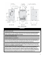
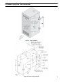
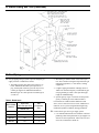
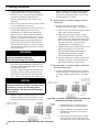
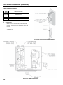
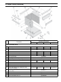
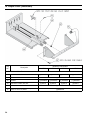
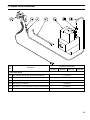
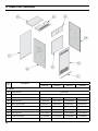
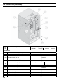
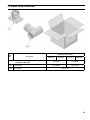
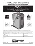
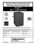
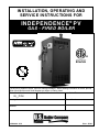
IN S TAL L AT ION , OP E R AT IN G AN D S E R V IC E IN S T R U C T ION S F OR IN D E P E N D E N C E ® P V G A S - F I R E D BO I L E R 9700609 For service or repairs to boiler, call hour heating contractor. When seeking information on boiler, provide Boiler Model Number and Serial Number as shown on Rating Label. Boiler Model Number Boiler Serial Number Installation Date IN__PVNI Heating Contractor Phone Number Address 103560-04 - 8/13 Price - $5.00 The New York City Department of Buildings has approved the Independence® PV boiler: Approval No. MEA 154-93-E. The City of New York requires a Licensed Master Plumber supervise the installation of this product. The Massachusetts Board of Plumbers and Gas Fitters has approved the Independence® PV boiler. See the Massachusetts Board of Plumbers and Gas Fitters website, http://license.reg.state.ma.us/pubLic/pl_products/pb_pre_form.asp for the latest Approval Code or ask your local Sales Representative. The Commonwealth of Massachusetts requires this product to be installed by a Licensed Plumber or Gas Fitter. The following terms are used throughout this manual to bring attention to the presence of hazards of various risk levels, or to important information concerning product life. DANGER CAUTION Indicates an imminently hazardous situation which, if not avoided, will result in death, serious injury or substantial property damage. Indicates a potentially hazardous situation which, if not avoided, may result in moderate or minor injury or property damage. WARNING NOTICE Indicates a potentially hazardous situation which, if not avoided, could result in death, serious injury or substantial property damage. Indicates special instructions on installation, operation, or maintenance which are important but not related to personal injury hazards. Table 1: Dimensions and Clearances Boiler Model Dimensions [inches] Minimum Clearances from Combustible Materials [inches] (B) Flue Left Right (A) Width Front Rear Top Connector Side Side IN3PVNI 14-1/2 Vent 4 IN4PVNI 17-3/4 8-1/4 IN5PVNI 21 9-1/4 IN6PVNI 24-1/4 9-1/4 Approx. Shipping Weight Lbs. 355 18 6 Alcove 6 12 * 425 490 560 * Vent pipe minimum clearance to combustible material is five (5) inches when vent is installed in a fully enclosed (chase) application or four (4) inches when vent is installed with at least one side open, similar to a joist bay application. Table 2: Purpose of Tappings Tapping Size IN3PVNI IN4PVNI - IN6PVNI A 2 Supply Plugged B 2 Plugged Supply C ½ Pressure Gauge (with ½ x ¼ bushing) D 2 Drain Valve (with 2 x ¾ bushing) E ¾ Safety Valve F 1 Surface Blow-Off, Plugged G ½ Gauge Glass H ¾ Limit (with ¾ x ¼ bushing) L ¾ Low Water Cut-Off M 1¼ Indirect Water Heater Return, Plugged N 1¼ Indirect Water Heater Supply, Plugged P ¾ Indirect Water Heater Control, Plugged R 2 Return 2 Figure 2: Tapping Locations Figure 1: Elevation Views WARNING This boiler requires regular maintenance and service to operate safely. Follow the instructions contained in this manual. Improper installation, adjustment, alteration, service or maintenance can cause property damage, personal injury or loss of life. Read and understand the entire manual before attempting installation, start-up, operation, or service. Installation and service must be performed only by an experienced, skilled, and knowledgeable installer or service agency. This boiler must be properly vented. This boiler needs fresh air for safe operation and must be installed so there are provisions for adequate combustion and ventilation air. The interior of the venting system must be inspected and cleaned before the start of the heating season and should be inspected periodically throughout the heating season for any obstructions. A clean and unobstructed venting system is necessary to allow noxious fumes that could cause injury or loss of life to vent safely and will contribute toward maintaining the boiler’s efficiency. This boiler is supplied with safety devices which may cause the boiler to shut down and not re-start without service. If damage due to frozen pipes is a possibility, the heating system should not be left unattended in cold weather; or appropriate safeguards and alarms should be installed on the heating system to prevent damage if the boiler is inoperative. This boiler contains very hot water or steam under pressure. Do not unscrew any pipe fittings nor attempt to disconnect any components of this boiler without positively assuring the water is cool and has no pressure. Always wear protective clothing and equipment when installing, starting up or servicing this boiler to prevent scald injuries. Do not rely on the pressure and temperature gauges to determine the pressure and temperature of the boiler. This boiler contains components which become very hot when the boiler is operating. Do not touch any components unless they are cool. 3 Table of Contents I.Pre-Installation................................... 4 VII. System Start-up................................ 17 II. Unpack Boiler.................................... 5 VIII. Service Instructions.......................... 25 III. Steam Piping and Trim....................... 6 IX. Repair Parts...................................... 32 IV. Gas Piping.......................................... 8 Appendix A - Figures........................ 40 V.Venting............................................ 10 Appendix B - Tables......................... 41 VI.Electrical.......................................... 16 WARNING Boiler materials of construction, products of combustion and the fuel contain alumina, silica, heavy metals, carbon monoxide, nitrogen oxides, aldehydes and/or other toxic or harmful substances which can cause death or serious injury and which are known to the state of California to cause cancer, birth defects and other reproductive harm. Always use proper safety clothing, respirators and equipment when servicing or working nearby the boiler. Failure to follow all instructions in the proper order can cause personal injury or death. Read all instructions, including all those contained in component manufacturers manuals which are provided with the boiler before installing, starting up, operating, maintaining or servicing. Keep boiler area clear and free from combustible materials, gasoline and other flammable vapors or liquids. All cover plates, enclosures and guards must be in place at all times. I. Pre-Installation A. Installation must conform to the requirements of the F. Provide combustion and ventilation air in accordance authority having jurisdiction. In the absence of such requirements, installation must conform to the National Fuel Gas Code, ANSI Z223.1/NFPA 54. Where required by the authority having jurisdiction, the installation must conform to the Standard for Controls and Safety Devices for Automatically Fired Boilers, ANSI/ASME CSD-1. with applicable provisions of local building codes, or National Fuel Gas Code, ANSI Z223.1/NFPA 54, Air for Combustion and Ventilation. The following guideline is based on the National Fuel Gas Code, ANSI Z223.1/NFPA 54. B. Boiler is design certified for installation on combustible 1. Determine volume of space (boiler room). Rooms communicating directly with space (through openings not furnished with doors) are considered part of space. C. Provide clearance between boiler jacket and flooring. The boiler must not be installed on carpeting. combustible material in accordance with local fire ordinance. Refer to Table 1 for minimum listed clearance from combustible material. Recommended service clearance is 24 inches from left side, right side and front. Service clearances may be reduced to minimum clearances to combustible materials. D. Install on level floor. For basement installation provide solid base, such as concrete, if floor is not level or if water may be encountered on floor around boiler. E. Protect gas ignition system components from water (dripping, spraying, rain, etc.) during boiler operation and service (circulator replacement, condensate trap, control replacement, etc.). 4 Volume [ft³] = Length [ft] x Width [ft] x Height [ft] 2. Determine Total Input of all appliances in space. Round result to nearest 1,000 Btu per hour (Btuh). 3. Determine type of space. Divide Volume by Total Input. a. If result is greater than or equal to 50 ft³ per 1,000 Btuh, space is considered an unconfined space. b. If result is less than 50 ft³ per 1,000 Btuh, space is considered a confined space. 4. Determine building type. A building of unusually tight construction has the following characteristics: a. Walls and ceiling exposed to outside atmosphere have a continuous water vapor retarder with a I. Pre-Installation (continued) rating of 1 perm or less with openings gasketed and sealed, and; b. Weather-stripping has been added on openable windows and doors, and; c. Caulking or sealants applied in joints around window and door frames, between sole plates and floors, between wall-ceiling joints, between wall panels, at plumbing and electrical penetrations, and at other openings. 5. For boiler located in an unconfined space in a building of other than unusually tight construction, adequate combustion and ventilation air is normally provided by fresh air infiltration through cracks around windows and doors. 6. For boiler located within unconfined space in building of unusually tight construction or within confined space, provide outdoor air through two permanent openings which communicate directly or by duct with the outdoors or spaces (crawl or attic) freely communicating with the outdoors. Locate one opening within 12 inches of top of space. Locate remaining opening within 12 inches of bottom of space. Minimum dimension of air opening is 3 inches. Size each opening per following: a. Direct communication with outdoors. Minimum free area of 1 square inch per 4,000 Btu per hour input of all equipment in space. b. Vertical ducts. Minimum free area of 1 square inch per 4,000 Btu per hour input of all equipment in space. Duct cross-sectional area shall be same as opening free area. c. Horizontal ducts. Minimum free area of 1 square inch per 2,000 Btu per hour input of all equipment in space. Duct cross-sectional area shall be same as opening free area. Alternate method for boiler located within confined space. Use indoor air if two permanent openings communicate directly with additional space(s) of sufficient volume such that combined volume of all spaces meet criteria for unconfined space. Size each opening for minimum free area of 1 square inch per 1,000 Btu per hour input of all equipment in spaces, but not less than 100 square inches. 7. Ventilation Duct Louvers and Grilles. Equip outside openings with louvers to prevent entrance of rain and snow, and screens to prevent entrance of insects and rodents. Louvers and grilles must be fixed in open position or interlocked with equipment to open automatically before burner operation. Screens must not be smaller than ¼ inch mesh. Consider the blocking effect of louvers, grilles and screens when calculating the opening size to provide the required free area. If free area of louver or grille is not known, assume wood louvers have 20-25 percent free area and metal louvers and grilles have 60-75 percent free area. G. Do not install boiler where gasoline or other flammable vapors or liquids, or sources of hydrocarbons (i.e. bleaches, cleaners, chemicals, sprays, paint removers, fabric softeners, etc.) are used or stored. CAUTION Avoid operating this boiler in an environment where saw dust, loose insulation fibers, dry wall dust, etc. are present. If boiler is operated under these conditions, the burner interior and ports must be cleaned and inspected daily to insure proper operation. II. Unpack Boiler CAUTION Do not drop boiler. Do not bump boiler jacket against floor. A. Move boiler to approximate installed position. B. Remove all crate fasteners. C. Lift outside container and remove with all other inside protective spacers and bracing. Save two of the wooden slats from the container sleeve for use in Steps E and F. D. Remove all boiler hold-down fasteners. E. Tilt the boiler to one side and slide a wooden slat under the two raised feet. F. Tilt the boiler to the other side and slide another wooden slat under the two raised feet. G. Slide the boiler forward or backward off the skid using the two wooden slats as runners. H. Move boiler to its permanent location. 5 III. Steam Piping and Trim WARNING Failure to properly pipe boiler may result in improper operation and damage to boiler or structure. Do not use softened water in steam boilers. Accelerated boiler corrosion will result. Tie in fresh water supply to the boiler upstream of a water softener. Oxygen contamination of boiler water will cause corrosion of iron and steel boiler components, and can lead to boiler failure. U.S. Boiler Company’s Standard Warranty does not cover problems caused by oxygen contamination of boiler water or scale (lime) build-up caused by frequent addition of water. NOTICE Before using copper for steam piping, consider the following characteristics of copper piping: 1) high coefficient of thermal expansion can induce mechanical stresses and cause expansion/ contraction noises if not accounted for in the piping system design and installation, 2) high heat transfer rate (heat loss) of uninsulated copper piping must be included in the normal piping and pickup factors used to size the boiler, 3) soldering or brazing pastes and fluxes that end up in the system can cause poor heat transfer, surging, an unsteady water line and wet steam if not thoroughly removed during the boil out procedure and, 4) galvanic corrosion of the adjoining metal may occur due to dissimilar metals in certain water chemistries if dielectric unions are not used. A. Design and install boiler and system piping to prevent D. Install Drain Valve in Tapping "D". See Figure 3. Use 2 E. Alliance SL™ Indirect Water Heater (if used). Refer oxygen contamination of boiler water. Oxygen contamination sources are system leaks requiring addition of makeup water, fittings, and oxygen permeable materials in distribution system. Eliminate oxygen contamination sources by repairing system leaks, repairing fittings, and using nonpermeable materials in distribution system. B. Connect system supply and return piping to boiler. Refer to Figure 4 for IN3PVNI or Figure 5 for IN4PVNI, IN5PVNI and IN6PVNI. Also consult Residential Hydronic Heating Installation and Design I=B=R Guide. Maintain minimum ½ inch clearance from combustible materials. C. Install Safety Valve in Tapping "E". See Figure 3. Use ¾ NPT x 3" nipple and ¾ NPT elbow provided. Safety Valve must be installed with spindle in vertical position. WARNING Installation is not complete unless a safety valve is installed. WARNING Safety valve discharge piping must be piped near floor to eliminate potential of severe burns. DO NOT pipe in any area where freezing could occur. DO NOT install any shut-off valves. 6 NPT x ¾ NPT bushing provided. to Alliance SL™ Installation, Operating and Service Instructions for additional information. 1. Supply and Return Piping. Connect supply piping to Tapping "N" and return piping to Tapping "M". See Figure 2. Install zone circulator and strainer in supply piping. Install check valve to prevent gravity circulation of boiler water. 2. Limit. Install temperature limit control (Honeywell L4006A or equal) in Tapping "P". See Figure 3. Set at 180°F to prevent steam production during non-space heating periods. F. Boiler, when used in connection with refrigeration system, must be installed so chilled medium is piped in parallel with boiler with appropriate valves to prevent chilled medium from entering boiler. G. Boiler piping system of hot water boiler connected to heating coils located in air handling units where they may be exposed to refrigerated air circulation must be equipped with flow control valves or other automatic means to prevent gravity circulation of boiler water during cooling cycle. III. Steam Piping and Trim (continued) Figure 3: Trim Installation Figure 4: Steam Piping, IN3PVNI 7 III. Steam Piping and Trim (continued) Figure 5: Steam Piping, IN4PVNI, IN5PVNI and IN6PVNI IV. Gas Piping A. Size gas piping. Design system to provide adequate gas 2. Maximum gas demand. Table 3 lists boiler input rate. Also consider existing and expected future gas utilization equipment (i.e. water heater, cooking equipment). supply to boiler. Consider these factors: 1. Allowable pressure drop from point of delivery to boiler. Maximum allowable system pressure is ½ psig. Actual point of delivery pressure may be less; contact gas supplier for additional information. Minimum gas valve inlet pressure for natural gas is 4.5 inch w.c. 4. Specific gravity of gas. Corrections for the specific gravity of natural gas can be found in Table 6. Table 3: Rated Input 8 Input Rate [cubic feet per hour] Natural Gas Gas Connection Size IN3PVNI 62 ½ IN4PVNI 105 ½ IN5PVNI 140 ½ IN6PVNI 175 ½ Boiler Model Number 3. Length of piping and number of fittings. Refer to Table 4 for maximum capacity of Schedule 40 pipe carrying natural gas. Table 5 lists equivalent pipe length for standard fittings. For materials or conditions other than those listed above, refer to National Fuel Gas Code, ANSI Z223.1/ NFPA 54, or size system using standard engineering methods acceptable to authority having jurisdiction. B. Connect boiler gas valve to gas supply system. 1. Use methods and materials in accordance with local plumbing codes and requirements of gas supplier. In absence of such requirements, follow National Fuel Gas Code, ANSI Z223.1/NFPA 54. IV. Gas Piping (continued) 2. Use thread (joint) compounds (pipe dope) resistant to action of liquefied petroleum gas. 4. All above ground gas piping upstream from manual shut-off valve must be electrically continuous and bonded to a grounding electrode. Do not use gas piping as grounding electrode. Refer to National Electrical Code, ANSI/NFPA 70. 3. Install sediment trap, ground-joint union and manual shut-off valve upstream of boiler gas control valve and outside jacket. See Figure 6. Table 4: Maximum Capacity of Schedule 40 Pipe in CFH of Natural Gas For Gas Pressures of 0.5 psig or Less 0.3 inch w.c. Pressure Drop 0.5 inch w.c. Pressure Drop Length [Feet] ½ ¾ 1 1¼ ½ ¾ 1 1¼ 10 132 278 520 1,050 175 360 680 1,400 20 92 190 350 730 120 250 465 950 30 73 152 285 590 97 200 375 770 40 63 130 245 500 82 170 320 660 50 56 115 215 440 73 151 285 580 60 50 105 195 400 66 138 260 530 70 46 96 180 370 61 125 240 490 80 43 90 170 350 57 118 220 460 90 40 84 160 320 53 110 205 430 100 38 79 150 305 50 103 195 400 Table 5: Fitting Equivalent Lengths Fitting Table 6: Specific Gravity Correction Factors for Natural Gas Nominal Pipe Size ½ ¾ 1 1¼ Specific Gravity Multiplier 45° Ell 0.7 1.0 1.2 1.6 0.55 1.40 90° Ell 1.6 2.1 2.6 3.5 0.60 1.00 Tee (As Elbow) 3.1 4.1 5.2 6.9 0.65 0.96 0.70 0.93 0.75 0.90 0.80 0.87 C. Pressure test. The boiler and its gas connection must be leak tested before placing boiler in operation. 1. Protect boiler gas control valve. For all testing over ½ psig, boiler and its individual shutoff valve must be disconnected from gas supply piping. For testing at ½ psig or less, isolate boiler from gas supply piping by closing boiler's individual manual shutoff valve. 2. Locate leaks using approved gas detector, a noncorrosive leak detection fluid, or other approved leak detection method. Do not use matches, candles, open flames, or other methods providing ignition source. Figure 6: Recommended Gas Piping 9 V. Venting NOTICE The gasketed vent system components pictured below in Figure A are being phased in and each vent component is interchangeable with the previously supplied gasket-less venting components. The newer vent components are generally quicker and easier to join, as they do not require the sealant application and their clamp bands are attached. In the event a gasketed vent component and a gasketless vent component must be interconnected, follow the instructions associated with Figure 8B or 8C. The two guiding principles of these instructions are as follows: 1) Any joining of vent components that involves at least one gasket-less vent component always requires the sealant application. 2) The female end of a gasket-less vent component always requires a clamp band, regardless of the design of the mating male vent component. Each gasket-less vent component is supplied with a clamp band and sealant. A Vent Transition Kit, part number 6116302, is available that contains one clamp band and one 3 ounce tube of sealant. Figure A: U.S. Boiler Company Vent A. General Guidelines 1. Vent system installation must be in accordance with National Fuel Gas Code, ANSI Z223.1 /NFPA 54, Venting of Equipment, or applicable provisions of local building codes. Contact local building or fire officials about restrictions and installation inspection in your area. This Category III venting system must be installed in accordance to these instructions. 2. This boiler requires a Special Gas Vent. The product is designed to use supplied AL 29-4C® Stainless Steel vent system components. The following manufacturer's offer similar AL 29-4C® components and are approved for use with this product: HeatFab - Saf-T-Vent (800-772-0739); Flex-L International - Star-34 (800-561-1980); Protech Systems, Inc. - FasNSeal™ (800-766-3473); and Z-Flex U. S., Inc. - Z-Vent (800-654-5600). The use of these alternate manufacturer's venting systems will require adapters to connect to the supplied vent connector and vent terminal. These adapters are not supplied with this boiler and should be obtained from the supplier of the alternate manufacturer's venting system. See Table 8 for complete parts list. WARNING Do not use this boiler with galvanized, 304 or 316 stainless steel or any other non AL29-4C® based vent systems. 10 3. Vent length restrictions are based on equivalent length of vent pipe (total length of straight pipe plus equivalent length of fittings). Maximum vent length is listed in Table 7. Do not exceed maximum lengths. Minimum vent length is 8 feet. Table 8 lists equivalent length for fittings. Do not include Vent Terminal in equivalent feet calculation. Table 7: Maximum Equivalent Vent Length IN3PVNI IN4PVNI IN5PVNI IN6PVNI 45 35 35 35 Table 8: Vent System Components Vent System Component Part Number Equivalent Feet of Pipe 3" Dia. Pipe x 1 Ft 8116296U 1 3" Dia. Pipe x 3 Ft 8116298U 3 3" Dia. Pipe x 5 Ft 8116300U 5 3" Dia. Pipe x Adjustable 8116319U Equal to Installed Length (1.1 to 1.7) 3" Dia. 90° Elbow 8116294U 5 3" Dia. 45° Elbow 8116292U 5 3" Dia. Horizontal Drain Tee 8116302U ½ 3" Dia. Vertical Drain Tee 8116304U 7½ 3" Single Wall Thimble 8116116 --- 3" Double Wall Thimble 103877-01 --- V. Venting (continued) 4. Do not install venting system components on the exterior of the building except as specifically required by these instructions. 5. Do not connect vent connectors serving appliances vented by natural draft into any portion of mechanical draft system operating under positive pressure. 6. Do not use cellular core PVC (ASTM F891), cellular core CPVC, or Radel® (polyphenolsulfone). 7. Do not cover non-metallic vent pipe and fittings with thermal insulation. Note: Non-metallic vent cannot be used with this boiler. B. Removal of Existing Boiler. For installations not involving the replacement of an existing boiler, proceed to Step C. When an existing boiler is removed from a common venting system, the common venting system is likely to be too large for proper venting of the remaining appliances. At the time of removal of an existing boiler, the following steps shall be followed with each appliance remaining connected to the common venting system placed in operation, while the other appliances remaining connected to the common venting system are not in operation: doors, windows, exhaust fans, fireplace dampers and any other gas burning appliance to their previous conditions of use. 7. Any improper operation of the common venting system should be corrected so the installation conforms with the National Fuel Gas Code, ANSI Z223.1 /NFPA 54,. When resizing any portion of the common venting system, the common venting system should be resized to approach the minimum size as determined using the appropriate tables in Chapter 13 of the National Fuel Gas Code, ANSI Z223.1 /NFPA 54. C. Install Vent Connector. 1. Remove vent connector from vent accessory carton. 2. Remove gaskets, orifice plate and hardware from blower outlet flange. 3. Assemble orifice plate gaskets, orifice plate, and vent connector. See Figure 7. 4. Secure vent connector with washers and locknuts. Do not overtighten. 1. Seal any unused openings in the common venting system. 2. Visually inspect the venting system for proper size and horizontal pitch and determine there is no blockage or restriction, leakage, corrosion, and other deficiencies which could cause an unsafe condition. 3. Insofar as is practical, close all building doors and windows and all doors between the space in which the appliances remaining connected to the common venting system are located and other spaces of the building. Turn on clothes dryers and any appliance not connected to the common venting system. Turn on any exhaust fans, such as range hoods and bathroom exhausts, so they will operate at maximum speed. Do not operate a summer exhaust fan. Close fireplace dampers. 4. Place in operation the appliance being inspected. Follow the Lighting (or Operating) Instructions. Adjust thermostat so appliance will operate continuously. 5. Test for spillage at the drafthood relief opening after 5 minutes of main burner operation. Use the flame of a match or candle, or smoke from a cigarette, cigar or pipe. 6. After it has been determined that each appliance remaining connected to the common venting system properly vents when tested as outlined above, return Figure 7: Vent Connector Installation D. Install Vent Pipe, General. 1. Plan venting system to avoid possible contact with plumbing or electrical wires. Start at vent connector. Work toward vent terminal. 2. Use non-combustible ¾ inch pipe strap to support horizontal runs and maintain vent location and slope while preventing sags in pipe. Do not restrict thermal expansion or movement. Maximum support spacing is 5 feet. Do not penetrate any part of the venting system with fasteners. 11 V. Venting (continued) 3. Provide and maintain minimum clearances to combustible materials. Use single wall thimble (Part No. 8116116) when penetrating combustible wall. Other wall thimble manufacturers are American Metal Products, Hart & Cooley, and Metal Fab. Silastic 732 RTV, Dow Corning Silastic 736 RTV, GE RTV106, Polybac #500 RTV, Sil-bond RTV 4500 (Acetoxy) and Sil-bond RTV 6500. Do not use other adhesives or sealants. E. Install Vent Pipe, U.S. Boiler Company Gasketed Vent System. 4. Once a vent pipe manufacturer and system is chosen never mix and match vent systems. 1. Procedure for Joining U.S. Boiler Company Gasketed Vent Pipe and Fittings. See Figure 8A. 5. If a non-standard length pipe is required, the use of the adjustable length pipe (P/N 8116319U) is recommended to complete a non-standard pipe length. This pipe requires a minimum installed length of 12¾ inch and can adjust across a 7 inch gap up to a maximum of 19¾ inch long. (Note for the adjustable pipe the installed length should be measured from the centerline of the bead on the male end of the first pipe to the end of the female pipe excluding the locking band of the second pipe with a single gasket.) a. Wipe the male end of each joint using an alcohol pad to remove any dirt and grease. b. Align weld seams in pipes and use a slight twisting motion to FULLY insert male end into female end of joint. Ensure bead in male end of pipe is below locking band and rest against the end of the female pipe. Verify the factoryinstalled gasket is not dislodged or cut. c. Tighten locking band by HAND with a 5/16" nut driver until snug plus ¼ turn. DO NOT SECURE JOINTS WITH SHEET METAL SCREWS OR POP RIVETS. DO NOT PUNCTURE THE VENT SYSTEM! WARNING Never exceed maximum installed length of 19¾ inches for adjustable length pipe. Risk of flue gas leakage is possible. Only in the event the adjustable length pipe is not sufficient a standard length pipe may be cut using the following procedure. Carefully cut pipe to length using a hacksaw with minimum 32 teeth per inch or circular saw with metal abrasive wheel. Remove male (bead) end only – female (bell) end accepts next fitting or pipe. d. Once the installation is complete, operate boiler and inspect all joints to ensure that flue gases and/or liquid condensate will not escape. F. Install Vent Pipe, U.S. Boiler Company Gasket-Less & Gasketed Vent System. 1. Procedure for joining the male end of U.S. Boiler Company Gasket-Less Vent with the female end of U.S. Boiler Company Gasketed Vent. See Figure 8B. NOTICE Cut must be square with pipe and filed or sanded smooth before joining. Carefully ensure roundness of cut pipe by hand with gloves before installing. Seal joint with RTV specified in this manual. 6. Seal all U.S. Boiler Company Gasket-Less vent, U. S. Boiler Company mixed vent (Gasket-Less and Gasketed) and field cut joints using Dow Corning Figure 8B: U.S. Boiler Company Gasket-Less Male and Gasketed Female Vent Joint Detail a. Clean the male end of each joint using an alcohol pad to remove any dirt and grease. b. Apply a continuous ¼ inch bead of sealant around male end of joint no more than 1/8 inch from end. Figure 8A: U.S. Boiler Company Gasketed Vent Joint Detail 12 c. Align weld seams in pipes and use a slight twisting motion to FULLY insert male end into female end of joint. Ensure bead in male V. Venting (continued) end of pipe is below locking band and rest against the end of the female pipe. Verify the factory-installed gasket is not dislodged or cut. d. Smooth sealant around joint for a continuous seal. Reapply sealant if necessary. e. Tighten locking band by HAND with a 5/16" nut driver until snug plus ¼ turn. DO NOT SECURE JOINTS WITH SHEET METAL SCREWS OR POP RIVETS. DO NOT PUNCTURE THE VENT SYSTEM! f. Once the installation is complete, operate boiler and inspect all joints to ensure that flue gases and/or liquid condensate will not escape. 2. Procedure for joining the female end of U.S. Boiler Company Gasket-Less Vent with the male end of U.S. Boiler Company Gasketed Vent. See Figure 8C. a. Clean joints of pipe or fittings using an alcohol pad to remove any dirt and grease. b. Slip a locking band over female (bell) end of pipe/fitting. c. Apply a continuous ¼ inch bead of sealant around male end of joint no more than 1/8 inch from end. d. Align weld seams in pipes and use a slight twisting motion to FULLY insert male end into female end of joint. e. Smooth sealant around joint for a continuous seal. Reapply sealant if necessary. f. Slip the locking band over joint and align closest bead in locking band with bead in male end of pipe. g. Tighten locking band by HAND with a 5/16" nut driver until snug plus ¼ turn. DO NOT SECURE JOINTS WITH SHEET METAL SCREWS OR POP RIVETS. DO NOT PUNCTURE THE VENT SYSTEM! h. Once the installation is complete, operate boiler and inspect all joints to ensure that flue gases and/or liquid condensate will not escape. Figure 8C: U.S. Boiler Company Gasket-Less Female and Gasketed Male Vent Joint Detail Figure 9: Horizontal Vent Installation G. Horizontal (Through Wall) Vent Installation. 1. Recommended Installation: Maintain minimum ¼ inch per foot slope in horizontal runs. Slope toward vent terminal. Position weld seams in vent pipes in all horizontal runs at the top to avoid condensate from lying on the seams. See Figure 9. 2. Alternate Installation: Maintain minimum ¼ inch per foot slope in horizontal runs. Slope toward boiler. Install a horizontal condensate drain tee after first elbow. Position seams in vent pipes in horizontal runs at top to avoid condensate from lying on the seams. NOTICE Moisture and ice may form on surfaces around vent terminal. To prevent deterioration, surfaces should be in good repair (sealed, painted etc.) 3. Vent terminal location restricted per following: a. Minimum 12 inches above grade or normally expected snow accumulation level, or 7 feet above grade if located adjacent to public walkway. Do not install over public walkway where local experience indicates condensate or vapor from Category III appliances creates a nuisance or hazard . b. Minimum 3 feet above any forced air inlet located within 10 feet. c. Minimum 4 feet below, 4 feet horizontally from, or 1 foot above any door, operable window, or gravity air inlet. d. Minimum of 4 feet horizontally from, and in no case above or below, unless a 4 foot horizontal distance is maintained, from electric meters, gas meters, regulators and relief equipment. e. Minimum 12 inches from overhang or corner. 4. Use single wall thimble when passing through combustible outside wall (thimble use optional for noncombustible wall). Insert thimble through wall 13 V. Venting (continued) Figure 10: Horizontal Vent Terminal from outside. Secure outside flange to wall with nails or screws, and seal with adhesive material. Install inside flange to inside wall, secure with nails or screws, and seal with adhesive material. 5. For noncombustible wall when thimble is not used, size opening such that female (bell) end with locking band attached cannot pass through. 6. Join vent terminal to vent pipe. Locate vent pipe such that bell/locking band is flush with outside wall (or outside flange of thimble, if used) when joined to inside vent piping. See Figure 10. 7. Insert vent pipe through thimble/opening from outside and join to vent system. Apply sealant between vent pipe and opening/thimble to provide weathertight seal. H. Vertical (Through Roof) Vent Installation 1. Install vertical vent drain tee. See Figures 11 and 12. Attach tee directly to elbow or horizontal pipe from elbow. 2. Slope horizontal runs minimum ¼ inch per foot. Slope toward vertical vent drain tee. Position weld seams in vent pipes in all horizontal runs at the top to avoid condensate from lying on the seams. 3. Install firestops at floor and ceiling where vent passes through floor, ceiling, or framed wall. The firestop must close the floor or ceiling opening between vent pipe and structure. 4. Enclose vent passing through unoccupied or occupied spaces above the boiler with materials having a fire resistance rating at least equal to the rating of adjoining floor or ceiling. Maintain minimum clearance to combustible materials. Note: For one- or two-family dwellings fire resistance rating requirement may not need to be met, but is recommended. 5. Whenever possible install vent straight through roof. Refer to Figure 13 if offset is necessary. Maintain minimum clearance to combustible materials. Figure 11: Vertical Vent Installation 14 V. Venting (continued) Table 9: Minimum Vent Height Above Roof Figure 12: Vertical Vent Tee Installation Figure 13: Attic Offset Figure 14: Vertical Vent Termination Roof Pitch Minimum Height [H] Flat to 6/12 1 ft. Over 6/12 to 7/12 1 ft. 3 in. Over 7/12 to 8/12 1 ft. 6 in. Over 8/12 to 9/12 2 in. Over 9/12 to 10/12 2 ft. 6 in. Over 10/12 to 11/12 3 ft. 3 in. Over 11/12 to 12/12 4 ft. Over 12/12 to 14/12 5 ft. Over 14/12 to 16/12 6 ft. Over 16/12 to 18/12 7 ft. Over 18/12 to 20/12 7 ft. 6 in. Over 20/12 to 18/12 8 ft. 6. Install Vent Terminal. See Figure 14. a. Locate roof opening to allow vertical vent penetration. Size opening to maintain minimum clearance from combustible materials. b. Install roof flashing. c. Extend vent pipe to maintain minimum height [H] above roof as specified in Table 9. Vent terminal must be minimum 2 feet horizontally from roof surface and minimum 8 feet from any vertical wall or similar obstruction. Provide bracing as required in Table 9. d. Install storm collar on vent pipe immediately above flashing. Apply sealant between vent pipe and storm collar. e. Attach Vent Terminal. 7. Install condensate drain line. Use 3/8 inch i.d. high temperature flexible tubing such as silicone rubber or EPDM. See Figure 12. a. Form condensate trap with 6 inch diameter loop. Secure loop with plastic cable tie. Fill with water. b. Secure to vertical vent tee with hose clamp or plastic cable tie. c. Run condensate drain line to floor drain or condensate pump. Condensate disposal must be acceptable to authority having jurisdiction. 15 VI. Electrical A. General Install wiring and ground boiler in accordance with requirements of authority having jurisdiction, or in absence of such requirements the National Electrical Code, ANSI/NFPA 70. B. Install thermostat. Locate on inside wall approximately 4 feet above floor. Do not install on outside wall, near fireplace, or where influenced by drafts or restricted air flow, hot or cold water pipes, lighting fixtures, television, or sunlight. Allow free air movement by avoiding placement of furniture near thermostat. C. Wire thermostat. Remove transformer from junction box. Provide Class II circuit between thermostat and boiler. Connect circuit to blue wires to provide power to thermostat. Connect circuit to brown wire to control boiler operation. Set thermostat heat anticipator to 0.4 amps. See Figure 15. D. Alliance SL™ Indirect Water Heater (if used) See Figure 15, Ladder Diagram. 1. Attach extension junction box to junction box. 2. Provide two wire circuit between junction box and temperature limit control (See Section III: Steam Piping and Trim, Paragraph E.2). Use one red and one orange wire if possible. Refer to Alliance SL™ Installation, Operating and Service Instructions. E.Wire boiler. Boiler is rated for 120 VAC, 60 hertz, less than 12 amperes. A separate electrical circuit must be run from the main electrical service with an over-current device/disconnect in the circuit. Connect circuit to black and white wires and green ground screw. A service switch is recommended and may be required by some local jurisdictions. See Figure 15. F. Mount transformer on junction box. Figure 15: Wiring Diagram 16 VII. System Start-up A. Safe operation and other performance criteria were met with gas manifold and control assembly provided on boiler when boiler underwent tests specified in American National Standard for Gas-Fired LowPressure Steam and Hot Water Boilers, ANSI Z21.13. B. Fill boiler with water to normal water line. C. Prepare to check operation. 1. Obtain gas heating value (in Btu per cubic foot) from gas supplier. 2. Adjust limit. Set cutout pressure (MAIN scale) on the pressure limit for (1) PSI and differential pressure (DIFF.) for .5 PSI. These pressures may be varied to suit individual requirements of the system. See Figure 25. 3. Connect manometer to gas manifold. Use 1/8 NPT tapping provided. 4. Temporarily turn off all other gas-fired appliances. D. Follow Operating Instructions to place boiler in operation. See Figure 21. E. Sequence of Operation See Figure 16. 1. If boiler fails to operate properly, see Troubleshooting Tree on pages 30 and 31. 2. Enhanced Electronic Ignition Module with single Status LED indicator. See Figure 17A “ Location of LED”. Figure 17A: Location of LED Table 10 “Ignition Module Terminal Crossreference” cross-references the ignition module terminal designations to the ignition terminal numbers in the wiring ladder diagrams. Table 11 “ Green LED Status Codes” provides green LED status codes and recommended service action where applicable. See Figure 18 for Troubleshooting Guide. 3. Flame Current Measurement Procedure See Figure 17B “Measuring Pilot Flame Current with Micro-ammeter”. Figure 16: Sequence of Operation 17 VII. System Start-up (continued) Table 10: Ignition Module Terminal Cross-Reference Ignition Module Terminal Designation Wiring Ladder Diagram Terminal Number MV 1 MV/PV 2 PV 3 GND 4 24V (GND) 5 24V 6 SPARK 9 Table 11: Green LED Status Codes Green LED Flash Codea Next System Action Recommended Service Action No “Call for Heat” N/A None Flash Fast Power up - internal check N/A None Heartbeat Normal startup - ignition sequence started (including prepurge) N/A None 4 Seconds ON then “x” flashes Device in run mode. “x” = flame current to the nearest µA. N/A None 2 5 minute Retry Delay - Pilot flame not detected during trial for ignition Initiate new trial for ignition after retry delay completed. If system fails to light on next trial for ignition check gas supply, pilot burner, spark and flame sense wiring, flame rod contamination or out of position, burner ground connection. 3 Recycle - Flame failed during run Initiate new trial for ignition. Flash code will remain through the ignition trial until flame is proved. If system fails to light on next trial for ignition, check gas supply, pilot burner, flame sense wiring, contamination of flame rod, burner ground connection. 4 Flame sensed out of sequence If situation self corrects within 10 seconds, control returns to normal sequence. If flame out of sequence remains longer than 10 seconds, control will resume normal operation 1 hour after error is corrected. Check for pilot flame. Replace gas valve if pilot flame present. If no pilot flame, cycle “Call for Heat.” If error repeats, replace control. 6 Control Internal Error Control remains in wait mode. When the fault corrects, control resumes normal operation. Cycle “Call for Heat”. If error repeats, replace control. 7 Flame rod shorted to ground Control remains in wait mode. When the fault corrects, control resumes normal operation. Check flame sense lead wire for damage or shorting. Check that flame rod is in proper position. Check flame rod ceramic for cracks, damage or tracking. 8 Low secondary voltage supply- (below 15.5 Vac) Control remains in wait mode. When the fault corrects, control resumes normal operation. Check transformer and AC line for proper input voltage to the control. Check with full system load on the transformer. OFF a Indicates Flash Code Descriptions: - Flash Fast: rapid blinking - Heartbeat: Constant ½ second bright, ½ second dim cycles. - 4 second solid on pulse followed by “x” 1 second flashes indicates flame current to the nearest µA. This is only available in run mode. - A single flash code number signifies that the LED flashes X times at 2Hz, remains off for two seconds, and then repeats the sequence. 18 VII. System Start-up (continued) a. Pilot flame current in micro amps can be measured using any standard micro-ammeter by inserting the meter probes into the module holes labeled FLAME CURRENT as shown in Figure 17B. b. Flame current must be measured with pilot valve open/pilot lit but the main valve closed. c. Disconnect MV lead wire from the module before measuring flame current. Trying to measure the pilot flame current in series with the wiring will not yield the accurate reading. d.The minimum steady pilot flame signal must be 1 μAmp (microampere) DC (direct current). e. For reliable operation the flame current should be 2 μAmp or greater. f. To ensure adequate flame current: i. Turn off boiler power at circuit breaker or fuse box ii. Clean the flame rod with emery cloth if required iii. Make sure electrical connections are clean and tight, and wiring not damaged, repair/ replace as needed iv. Check for igniter/sensor cracked ceramic insulator, replace if needed v. Check the pilot flame. It must be blue, steady and envelop the flame sensing rod 3/8” to ½”. vi. If needed, adjust pilot flame by turning the gas valve pilot adjustment screw clockwise to decrease or counterclockwise to increase pilot flame. Always reinstall pilot adjustment screw cover and tighten securely upon completion to assure proper gas valve operation. g. Reconnect MV lead wire to the module upon satisfactory completion of pilot flame current measurement. h. Check the pilot burner operation/ignition sequence during ignition cycle: i. Restore boiler power at circuit breaker or fuse box ii. Set thermostat to call for heat iii. Watch ignition sequence at burner iv. If spark does not stop after pilot lights, replace ignition module v. If main burners do not light or if main burners light but system locks out, check the module ground wire and gas control as described in Figure 18 “ Honeywell Electronic Ignition Troubleshooting Guide” Figure 17B: Measuring Pilot Flame Current with Micro-ammeter 19 VII. System Start-up (continued) Honeywell Electronic Ignition Troubleshooting Guide "CALL FOR HEAT." POWER TO MODULE? (24 V NOMINAL) NO CHECK LINE VOLTAGE POWER, LOW VOLTAGE TRANSFORMER, LIMIT CONTROLLER, THERMOSTAT (CONTROLLER), AND WIRING. ALSO, CHECK AIR PROVING SWITCH ON COMBUSTION AIR BLOWER SYSTEM (IF USED) AND THAT THE VENT DAMPER END SWITCH (IF USED) IS MADE. YES 30 SECOND PREPURGE DELAY?(S8670 ONLY) NO REPLACE S8670 YES PULL IGNITION LEAD AND CHECK SPARK AT MODULE. SPARK ACROSS IGNITOR/ SENSOR GAP? SPARK OK? NO REPLACE MODULE NO YES CHECK IGNITION CABLE, GROUND WIRING, CERAMIC INSULATOR, AND SPARK GAP AND CORRECT. CHECK BOOT OF THE IGNITION CABLE FOR SIGNS OF MELTING OR BUCKLING. TAKE PROTECTIVE ACTION TO SHIELD CABLE AND BOOT FROM EXCESSIVE TEMPERATURES. YES TURN GAS SUPPLY ON AND RECYCLE "CALL FOR HEAT." PILOT BURNER LIGHTS? CHECK THAT ALL MANUAL GAS VALVES ARE OPEN, SUPPLY TUBING AND PRESSURES ARE GOOD, AND PILOT BURNER ORIFICE IS NOT BLOCKED (PILOT GAS FLOWING). CHECK ELECTRICAL CONNECTIONS BETWEEN MODULE AND PILOT OPERATOR ON GAS CONTROL. CHECK FOR 24 VAC ACROSS PV-MV/PV TERMINALS ON MODULE, IF VOLTAGE IS OK, REPLACE GAS CONTROL. IF NOT, REPLACE MODULE. NOTE: IT MAY BE NECESSARY TO RECYCLE THE "CALL FOR HEAT" MORE THAN ONCE TO CLEAR THE PILOT SUPPLY TUBES OF AIR. NO YES SPARK STOPS WHEN PILOT IS LIT? NO NOTE: IF CONTROL GOES INTO LOCKOUT OR RETRY DELAY, RESET THE "CALL FOR HEAT." CHECK CONTINUITY OF IGNITION CABLE AND GROUND WIRE. CLEAN FLAME ROD. CHECK ELECTRICAL CONNECTIONS BETWEEN FLAME ROD AND MODULE. CHECK FOR CRACKED CERAMIC FLAME ROD INSULATOR. CHECK THAT PILOT FLAME COVERS FLAME ROD AND IS STEADY AND BLUE. ADJUST PILOT FLAME. IF PROBLEM PERSISTS, REPLACE MODULE. NO CHECK FOR 24 VAC ACROSS PV-MV/PV TERMINALS ON MODULE. IF NO VOLTAGE, REPLACE MODULE. CHECK ELECTRICAL CONNECTIONS BETWEEN MODULE AND GAS CONTROL INCLUDING SAFETY CONTROLS WIRED IN THE CIRCUIT. IF OKAY, REPLACE GAS CONTROL. NO NOTE: IF CONTROL GOES INTO LOCKOUT OR RETRY DELAY, RESET THE "CALL FOR HEAT." CHECK CONTINUITY OF IGNITION CABLE AND GROUND WIRE. NOTE: IF GROUND IS POOR OR ERRATIC, SHUTDOWNS MAY OCCUR OCCASIONALLY EVEN THOUGH OPERATION IS NORMAL AT THE TIME OF CHECKOUT. CHECK THAT PILOT FLAME COVERS FLAME ROD AND IS STEADY AND BLUE. PILOT FLAME MUST NOT BE MOVING AROUND DUE TO OUTSIDE AIR FLOWS, ETC. ADJUST PILOT FLAME. CHECK GAS PRESSURE MEETS APPLIANCE SPECIFICATIONS WHILE APPLIANCE MAIN BURNER IS ON AND ALL OTHER GAS APPLIANCES ON THE SUPPLY ARE OPERATING AT FULL RATE. IF CHECKS ARE OKAY, REPLACE MODULE. NO CHECK FOR PROPER THERMOSTAT (CONTROLLER) OPERATION. REMOVE MV LEAD AT MODULE. IF VALVE CLOSES, RECHECK TEMPERATURE CONTROLLER AND WIRING. IF NOT, REPLACE GAS CONTROL. YES MAIN BURNER LIGHTS? YES SYSTEM RUNS UNTIL "CALL FOR HEAT" ENDS? YES "CALL FOR HEAT" ENDS SYSTEM SHUTS OFF? 20 Figure 18: Troubleshooting Guide VII. System Start-up (continued) F. Check pilot burner flame. See Figure 19. Flame should be steady, medium hard blue enveloping 3/8 to ½ inch of sensing probe. J. Check low water cutoff. 1. Adjust thermostat to highest setting. 2. With boiler operating, open drain valve and slowly drain boiler. CAUTION Do not drain below gauge glass. 3. Main burners and pilot burner will extinguish and blower stop when water level drops below low water cutoff probe. Verify limit, thermostat or other controls have not shut off boiler. 4. Adjust thermostat to lowest setting. Refill boiler to normal water line. K. Check limit. 1. Adjust thermostat to highest setting. 2. Observe pressure gauge. When pressure is indicated, adjust limit to setting below observed pressure. Main burners and pilot burner should extinguish, and blower stop. Figure 19: Pilot Burner Flame G. Check main burner flame. See Figure 20. Flame should have clearly defined inner cone with no yellow tipping. Orange-yellow streaks should not be confused with true yellow tipping. 3. Adjust limit to setting above observed pressure. Ignition sequence should begin. 4. Adjust thermostat to lowest setting. Adjust limit to desired setting. L. Adjust gas input rate to boiler. 1. Adjust thermostat to highest setting. 2. Check manifold gas pressure. Pressure should be as printed on the rating label. Adjust gas valve pressure regulator as necessary (turn adjustment screw counterclockwise to decrease manifold pressure, or clockwise to increase manifold pressure). If specified pressure can not be attained, check gas valve inlet pressure. If less than 4.5 inch w.c., contact gas supplier for assistance. 3. Clock gas meter for at least 30 seconds. Use Table 13 to determine gas flow rate in Cubic Feet per Hour. 4. Determine Input Rate. Multiply gas flow rate by gas heating value. Figure 20: Main Burner Flame H. Check thermostat operation. Raise and lower temperature setting to start and stop boiler operation. I. Check ignition control module shutoff. Disconnect igniter/sensor cable from Terminal 9 (SPARK). Gas valve should close and pilot and main burners extinguished. 5. Compare measured input rate to input rate stated on rating label. a. Boiler must not be overfired. Reduce input rate by decreasing manifold pressure. Do not reduce by more than 0.3 inch w.c. If boiler is still overfired, contact your U.S. Boiler distributor or Regional Office for replacement Gas Orifice. b. Increase input rate if less than 98% of rating label input. Increase manifold gas pressure by as much as 0.3 inch w.c. If measured input rate is still less than 98% of rated input: 21 VII. System Start-up (continued) Figure 21: Operating Instructions i. Remove Main Burners per procedure in Section VIII: Service. ii. Remove gas orifices. Drill one (1) drill size larger (drill size is stamped on orifice, or see Key No. 4D). iii. Reinstall gas orifices and main burners. Measure input rate. 22 6. Recheck Main Burner Flame. 7. Return other gas-fired appliances to previous conditions of use. M. Clean Heating System. Oil from new piping connections and sediment in existing piping must be removed from system to prevent unsteady water line and carry-over of entrained water into supply main. VII. System Start-up (continued) Table 13: Gas Flow Rate in Cubic Feet per Hour Size of Gas Meter Dial Seconds for One Revolution One-Half Cu. Ft. 30 60 120 240 32 56 113 225 34 53 106 212 36 50 100 200 38 47 95 189 40 45 90 180 42 43 86 172 44 41 82 164 46 39 78 157 1. Run 1 NPT pipe from Surface Blow-Off Tapping "F" to open drain. Do not install shut-off valve or other restriction. 48 37 75 150 2. Fill boiler to top of gauge glass. 50 36 72 144 3. Remove safety valve. 52 35 69 138 54 33 67 133 4. Pour recommended boil-out compound into boiler through safety valve opening. 56 32 64 129 58 31 62 124 60 30 60 120 6. Follow Operating Instructions to place boiler in operation. See Figure 21. Boil water for approximately 5 hours without producing steam. 2. Follow Operating Instructions to place boiler in operation. See Figure 21. 7. Open boiler fill shut-off valve to produce steady trickle of water from surface blow-off pipe. Continue boil-out for several hours until surface blow-off water runs clear. 3. Operate boiler with steam in entire system for several days to bring system oil and dirt back to boiler. 8. Follow instructions TO TURN OFF GAS TO APPLIANCE. See Figure 21. Drain boiler and system piping. 4. Drain condensate from drain valve in wet return. Operate boiler until condensate runs clean. 9. Remove drain valve. Thoroughly wash boiler water passages with high pressure spray through drain valve tapping. One Cu. Ft. Two Cu. Ft. 1. Fill boiler to normal waterline. 6. Follow Operating instructions to place boiler in operation. See Figure 21. Check controls operation per Paragraphs F to K. Boil water for at least 5 hours. A local qualified water treatment chemical specialist is a suggested source for recommendations regarding appropriate chemical compounds and concentrations which are compatible with local environmental regulations. N. Boil-out Boiler. 1. Follow instructions TO TURN OFF GAS TO APPLIANCE. See Figure 21. 2. Fill boiler to normal waterline. 3. Remove safety valve. 4. Pour recommended boil-out compound into boiler through safety valve opening. 5. Reinstall safety valve in Tapping "E" with spindle in vertical position. 7. Follow instructions TO TURN OFF GAS TO APPLIANCE. See Figure 21. Drain boiler and system piping. 8. Remove drain valve. Thoroughly wash boiler water passages with high pressure spray through drain valve tapping. 9. Reinstall drain valve in Tapping "D". O. Second Boilout for Stubborn Cases. If all oil and grease is not removed a second boilout using surface blow-off is necessary. 5. Reinstall safety valve in Tapping "E" with spindle in vertical position. 10. Fill boiler to normal waterline. If water in gauge glass is not clear, repeat procedure starting at step 2. 11. Remove surface blow-off piping. Install 1 NPT plug in Tapping "F". If unsteady water line, foaming or priming persist: 12.Follow Operating Instructions to place boiler in operation. See Figure 21. 13. Install gate valve (shut-off valve) in Hartford Loop. Install drain valves in return main and at boiler. See Figure 4 or 5. 14. Connect hoses from drain valves to floor drain. Close gate valve in Hartford Loop. Open drain valve in return main. 23 VII. System Start-up (continued) 15. Fill boiler to normal water line. Follow Operating Instructions to place boiler in operation. See Figure 21. 16. Operate boiler for at least 30 minutes after condensate begins to run hot. Follow instructions TO TURN OFF GAS TO APPLIANCE. See Figure 21. 17. Close all radiator valves. Remove all supply main air valves. Plug openings in supply main. 18. Drain approximately 5 gallons of boiler water into container. Mix in recommended boil-out compound. 25. Drain second quart sample from lower Gauge Glass fitting. If sample is not clear, repeat cycle of draining boiler and return main and refilling boiler until sample is clear. 26. If after normal operation boiler water becomes dirty from additional system piping sediment returning to boiler. a. Complete steps 12 through 25. b. Complete steps 1 through 11. P. Add Boiler Water Treatment 1. Remove safety valve. 19. Remove safety valve. Pour recommended compound into boiler through safety valve opening. Reinstall safety valve in Tapping "E" with spindle in vertical position. 2. Pour recommended compound into boiler through safety valve opening. 20. Follow Operating Instructions to place boiler in operation. See Figure 21. Slowly feed water to boiler. Water will rise slowly into supply main and back through return main. Adjust flow to maintain approximately 180°F water from return main hose. Continue until water runs clear from hose for at least 30 minutes. 4. Follow Operating Instructions to place boiler in operation. See Figure 21. 21. Turn off water to boiler. Continue to operate until excess water is removed from boiler and system (by steaming) and boiler water reaches normal waterline. 22. Follow instructions TO TURN OFF GAS TO APPLIANCE. See Figure 21. Open all radiator valves. Reinstall all supply main air valves. Open gate valve in Hartford Loop. 23. Allow boiler to cool until crown sheet is no longer too hot to touch. Close drain valves at boiler and in return main. Fill boiler slowly to normal waterline. 24. Follow Operating Instructions to place boiler in operation. See Figure 21. Allow boiler to steam for 10 minutes. Drain one quart of water from lower Gauge Glass fitting. 24 3. Reinstall safety valve in Tapping "E" with spindle in vertical position. 5. Boil water or heat water to 180°F. 6. Test the pH of the water in the system. This can easily be done by drawing a small sample of boiler water and testing with Hydrion paper which is used in the same manner as litmus paper, except it gives specific readings. A color chart on the side of the small Hydrion dispenser gives the reading in pH. Hydrion paper is inexpensive and obtainable from any chemical supply house or through your local druggist. The pH should be higher than 7 but lower than 11. Add recommended water treatment chemicals, if necessary, to bring the pH within the specified range. With this lower level of protection, care must be exercised to eliminate all of the free oxygen in the system. 7. Boiler is now ready to be put into service. Q. Review User's Information Manual and system operation with owner or operator. VIII. Service Instructions Important Product Safety Information Refractory Ceramic Fiber Product Warning: The Repair Parts list designates parts that contain refractory ceramic fibers (RCF). RCF has been classified as a possible human carcinogen. When exposed to temperatures about 1805°F, such as during direct flame contact, RCF changes into crystalline silica, a known carcinogen. When disturbed as a result of servicing or repair, these substances become airborne and, if inhaled, may be hazardous to your health. AVOID Breathing Fiber Particulates and Dust Precautionary Measures: Do not remove or replace RCF parts or attempt any service or repair work involving RCF without wearing the following protective gear: 1. A National Institute for Occupational Safety and Health (NIOSH) approved respirator 2. Long sleeved, loose fitting clothing 3. Gloves 4. Eye Protection • • • • Take steps to assure adequate ventilation. Wash all exposed body areas gently with soap and water after contact. Wash work clothes separately from other laundry and rinse washing machine after use to avoid contaminating other clothes. Discard used RCF components by sealing in an airtight plastic bag. RCF and crystalline silica are not classified as hazardous wastes in the United States and Canada. First Aid Procedures: • • • • If contact with eyes: Flush with water for at least 15 minutes. Seek immediate medical attention if irritation persists. If contact with skin: Wash affected area gently with soap and water. Seek immediate medical attention if irritation persists. If breathing difficulty develops: Leave the area and move to a location with clean fresh air. Seek immediate medical attention if breathing difficulties persist. Ingestion: Do not induce vomiting. Drink plenty of water. Seek immediate medical attention. 25 VIII. Service Instructions (continued) A. General Inspection and service should be conducted annually. Turn off electrical power and gas supply while conducting service or maintenance. Follow instructions TO TURN OFF GAS TO APPLIANCE. See Figure 21. CAUTION Label all wires prior to disconnection when servicing controls. Wiring errors can cause improper and dangerous operation. Verify proper operation after servicing. B. Low water cutoff Clean probe. 1. Drain boiler to point below Tapping "L". 2. Disconnect the (3) wire multi pin connector from the control and disconnect the control's black wire from the probe's screw terminal. 3. Remove control from probe. 4. Unscrew probe from Tapping "L". NOTICE Carefully remove, clean, and reinstall probe. Platinum guard ring must not be exposed to rough treatment, or useful life of probe may be shortened. 5. Remove deposits from probe using diluted phosphoric acid (H2PO4) solution, 3 parts water to 1 part phosphoric acid. Normal operation will occur with up to 0.2 inch of contamination. If scale or contamination exceeds 0.2 inches clean probe more frequently. 6. Reinstall probe in Tapping "L". Mount control on probe. Attach control's black wire to probe's screw terminal and reconnect the (3) wire multi pin connector to the control. C. Water Feeder and Additional Low Water Cut-Off Refer to manufacturer's instructions. D. Vent System Inspect for obstructions, soot accumulation, proper support, and deterioration of pipe, fittings, and joints. 1. Clean vent terminal screens. Vent terminal must be free of obstruction, undamaged, with screens securely in place. 2. Vent terminal and wall thimble (if used) must be weather-tight. 3. Vent pipe must be full round shape, and show no damage from impact or excessive temperature. 26 4. Vent pipe must be supported at minimum 5 foot intervals and must not sag. 5. All joints must be secure and watertight. 6. Condensate drain must have minimum 6 inch trap and allow condensate to flow freely. To clean: a. Disconnect condensate drain from drain fitting. b. Flush condensate drain with water. Fill trap with water. c. Securely fasten condensate drain to drain fitting, providing gas-tight and watertight seal. 7. If vent pipe must be disassembled for removal of obstructions or resealing of joint, see Venting Section. E. Boiler Flue Passages. Inspect for blockage or soot accumulation. 1. Remove Main Burners. a. Disconnect Pilot Tubing from Gas Valve. b. Disconnect Igniter/Sensor Wire and Pilot Ground Wire from Ignition Module. c. Disconnect (2) wires to Flame Roll-out Switch. d. Remove Burner Access Panel. e. Mark manifold with location of Main Burner with Pilot Bracket. f. Hold Main Burner on throat. Lift slightly to clear orifice. Pull Main Burner from combustion chamber. Main Burner with Pilot Bracket can only be removed by lifting at 45° angle after adjacent Main Burner to right is removed. 2. Disconnect Junction Box to Vestibule Wiring Harness from Blower. 3. Remove (4) locknuts securing vent connector. See Figure 7. Disconnect vent connector and vent pipe from blower outlet. 4. Remove Jacket Top Panels. 5. Disconnect Silicone Tubing from Canopy. Pull tubing through Blower Access Panel into vestibule. 6. Remove Blower Access Panel. 7. Loosen (4) carriage bolts. Remove Canopy/Blower Assembly. 8. Remove Gasket and Flue Gas Baffles. Inspect Flue Baffles for deterioration. 9. Inspect flue passages. Clean with flue brush. See Figure 22. 10. Inspect heating surface in combustion chamber. Clean with straight handle wire brush. 12. Install Flue Gas Baffles. 13. Install new Gasket (Key No. 2E). Do not reuse existing material. VIII. Service Instructions (continued) Table 14: Pilot Burner Location Boiler Model Main Burner with 60° Pilot Bracket * Pilot Burner Located Between Main Burners * IN3PVNI 1 1&2 IN4PVNI 2 2&3 IN5PVNI 3 3&4 IN6PVNI 4 4&5 * Main burners numbered left to right as viewed from front of boiler. Figure 22: Cleaning Boiler Flue Passages Figure 23: Main Burner Installation 14. Install Canopy/Blower Assembly. Tighten Carriage Bolts to fully compress Gasket. c. Pilot gas supply, igniter/sensor cable and ground wire must be reconnected. d. Burner access panel must be securely in place. e. Flame rollout switch wires must be reconnected. 15. Install Blower Access Panel. 16. Connect Silicone Tubing between Pressure Fitting on Canopy Assembly and Pressure Switch. Route through bushings in Blower Access Panel and Canopy Assembly. 17. Install Jacket Top Panels. 18. Connect vent system. See Figure 7. 19. Connect Blower to Junction Box to Vestibule Wiring Harness. F. Main Burners and Firebox 1. Vacuum firebox. Exercise care - do not damage base insulation. 2. Clean main burners. Brush top of burners with soft bristle brush. Vacuum to remove any dirt and lint. 3. Vacuum tip of pilot burner. 4. Check gas orifices for lint and dirt. Clean as necessary. 5. Install main burners by reversing procedure to remove burners. a. Pilot burner must be installed in original location. See Table 14. b. Main burners must be properly secured in burner tray slot at rear of firebox and over gas orifice. See Figure 23. G. Check operation. Follow steps B through L from Section VII: System Start-up. H. Procedure for Measuring Fan Inlet Pressure (vacuum), See Figure 24. 1. With boiler off, remove hose at pressure switch. 2. With Tee and ¼ inch aluminum stubs, connect water manometer as shown with additional tubing. 3. Start boiler and read Pressure on Manometer when boiler water temperature reaches operating temperature. Refer to Table 15 for minimum readings. NOTE: If switch drops-out before boiler reaches temperature or if pressure readings are below minimums shown in Table 15, check for cracks in hose or contact your nearest U.S. Boiler Company representative. 4. Stop boiler, remove manometer and reconnect hose to pressure switch. See Figure 24. 27 VIII. Service Instructions (continued) Table 15: Minimum Vacuum Boiler Model Minimum Vacuum IN3PVNI -0.40 inches w.c. IN4PVNI -0.40 inches w.c. IN5PVNI -0.70 inches w.c. IN6PVNI -0.70 inches w.c. I.Housekeeping 1. Boiler area to be clear and free from combustible materials, gasoline and other flammable vapors and liquids. 2. Remove obstructions to flow of combustion and ventilation air. Figure 24: Inlet Fan Vacuum Measurement 28 Figure 25: L404F Pressuretrol SERVICE RECORD DATESERVICE PERFORMED 29 TURN OFF GAS SUPPLY. ADJUST THERMOSTAT TO CALL FOR HEAT. NO DOES BLOWER ENERGIZE? GO TO PAGE 31 YES SPARK PRESENT AT PILOT IGNITER/ SENSOR? NO 24 VOLTS AT SUCTION PRESSURE SWITCH TERMINAL 'NO'? YES NO YES DISCONNECT IGNITER/SENSOR CABLE FROM IGNITION MODULE TERMINAL (9). HOLD CABLE NO NEAR TERMINAL. IS SPARK PRESENT? NO HOSE SECURELY NO CONNECT HOSE CONNECT MANOMETER TO TO CANOPY CONNECTED TO SUCTION PRESSURE SWITCH CANOPY? (SEE Figure 24). IS SUCTION PRESSURE GREATER THAN: YES -0.50 IWC FOR IN3PVNI/IN4PVNI -0.80 IWC FOR IN5PVNI/IN6PVNI HOSE FREE OF NO CRACKS OR REPLACE HOSE YES HOLES? REPLACE SUCTION PRESSURE SWITCH YES VENT SYSTEM NO CLEAR FREE OF OBSTRUCTIONS OBSTRUCTIONS? REPLACE IGNITION MODULE YES YES REPLACE BLOWER CHECK IGNITER/SENSOR CABLE, GROUND WIRE, CERAMIC INSULATOR, AND GAP. CHECK IGNITER/SENSOR CABLE BOOT FOR SIGNS OF MELTING OR BUCKLING. DID BLOWER OPERATE FOR 30 TO 50 SECONDS BEFORE SPARK BEGAN? NO REPLACE IGNITION MODULE YES TURN ON GAS SUPPLY. DOES PILOT BURNER LIGHT? NO ALL MANUAL GAS VALVES OPEN? NO OPEN VALVES YES 24 VOLTS ACROSS GAS VALVE TERMINALS 'PV' AND 'MV-PV'? YES NO 24 VOLTS ACROSS IGNITION MODULE TERMINALS 'PV' AND 'MV-PV'? NO REPLACE IGNITION MODULE NO CONTACT GAS SUPPLIER YES YES REPAIR OR REPLACE WIRES IS PILOT BURNER ORIFICE BLOCKED? NO YES YES CLEAN OR REPLACE PILOT BURNER ORIFICE DOES SPARK STOP AFTER PILOT IS LIT? NO YES MAIN BURNER LIGHTS? YES BOILER CONTROL SYSTEM SEQUENCING PROPERLY. CHECK DISTRIBUTION SYSTEM 30 NO IS GAS SUPPLY PRESSURE BETWEEN 4.5 AND 13.5 IWC? REPLACE GAS VALVE CHECK CONTINUITY OF IGNITION CABLE AND GROUND WIRE. CLEAN FLAME ROD. CHECK ELECTRICAL CONNECTIONS BETWEEN FLAME ROD AND IGNITION MODULE. CHECK FOR CRACKED CERAMIC FLAME ROD INSULATOR. CHECK PILOT FLAME (SEE Figure 19). IF CHECKS OKAY, REPLACE IGNITION MODULE. 24 VOLTS ACROSS GAS VALVE TERMINALS 'MV' AND 'MV-PV'? YES REPLACE GAS VALVE NO 24 VOLTS ACROSS IGNITION MODULE TERMINALS 'MV' AND 'MV-PV'? YES REPAIR OR REPLACE WIRES NO REPLACE IGNITION MODULE Troubleshooting Tree for Section VII, Step E WATERLINE ABOVE LOWEST PERMISSIBLE LEVEL? NO FILL BOILER TO NORMAL WATERLINE YES GAUGE PRESSURE LESS THAN LIMIT CUT-IN SETTING? NO ALLOW SYSTEM PRESSURE TO FALL BELOW LIMIT CUT-IN PRESSURE, OR INCREASE LIMIT CUT-IN SETTING. YES CAUTION NO CONTINUITY ACROSS FLAME ROLLOUT SWITCH (FRS)? YES 24 VOLTS AT SPST RELAY COIL? NO YES REPLACE FLAME ROLLOUT SWITCH. DETERMINE CAUSE OF EXCESSIVE TEMPERATURE (BLOCKED FLUE, EXCESSIVE RATE CAUSED BY HIGH MANIFOLD PRESSURE OR OVERSIZED ORIFICES, SUCTION PRESSURE SWITCH FAILURE, ETC.) BEFORE PLACING BOILER IN OPERATION. 24 VOLTS ACROSS TRANSFORMER BLUE AND YELLOW WIRES? NO NO NO PROVIDE POWER TO BOILER YES YES REPLACE TRANSFORMER AFTER CHECKING FOR BROKEN WIRES AND LOOSE CONNECTIONS. REPLACE THERMOSTAT AFTER CHECKING FOR BROKEN WIRES AND LOOSE CONNECTIONS. 24 VOLTS AT SPST RELAY TERMINALS '1' AND '3'? 120 VOLTS ACROSS TRANSFORMER BLACK AND WHITE WIRES? REPLACE RELAY AFTER CHECKING FOR BROKEN WIRES AND LOOSE CONNECTIONS. YES 24 VOLTS AT SUCTION PRESSURE SWITCH TERMINAL 'NC'? NO 24 VOLTS AT BOTH L.W.C.O. TERMINALS 'B-B'? NO REFER TO L.W.C.O. MANUFACTURER'S TROUBLESHOOTING INSTRUCTIONS NO REPLACE LIMIT AFTER CHECKING FOR BROKEN WIRES AND LOOSE CONNECTIONS. YES YES 24 VOLTS ACROSS BOTH LIMIT TERMINALS? YES CHECK FOR BROKEN WIRES AND LOOSE CONNECTIONS. 24 VOLTS AT SUCTION PRESSURE SWITCH TERMINAL 'C'? NO REPLACE SUCTION PRESSURE SWITCH. YES CHECK DPST RELAY: 24 VOLTS AT COIL? 120 VOLTS AT TERMINALS '1' AND '3'? NO REPLACE RELAY AFTER CHECKING FOR BROKEN WIRES AND LOOSE CONNECTIONS. YES REPLACE BLOWER AFTER CHECKING FOR BROKEN WIRES AND LOOSE CONNECTIONS. 31 IX. Repair Parts All Independence® PV Repair Parts may be obtained through your local U.S. Boiler Company Wholesale distributor. Should you require assistance in locating a U.S. Boiler Company Distributor in your area, or have questions regarding the availability of U.S. Boiler Company products or repair parts, please contact U.S. Boiler Company Customer Service at (717) 481-8400 or Fax (717) 481-8408. Key No. Description 1. Section Assembly [Quantity] Part Number IN3PVNI IN4PVNI IN5PVNI IN6PVNI 61710033 61710043 61710053 61710063 [1] 611100301 [1] 611100401 [1] 611100501 [1] 611100601 2. Canopy/Blower Assembly 2A Canopy 2B Carriage Bolt, 1/4 -20 x 1" [4] 80860115 2C Washer, 1/4, USS, Plated [4] 80860603 2D Nut, 1/4 -20, Heavy Hex, Plated [4] 80860407 2E Gasket [1] 6206001 2F Blower Mounting Gasket [Included in Key No. 2J] 2G Washer, 1/4", SAE 2H Hex Nut, 1/4 -20, Brass [(4) Included in Key No. 2J] 2J Blower [1] 6111714 [1] 6111715 2K Orifice Plate Gasket [(2) Included in Key No. 2J] [2] 8206042 [2] 8206035 2L Orifice Plate [1] 8206048 [1] 8206049 [4] 80860633 [4] 80860424 [1] 61110036 [1] 61110046 [1] 61110056 2M Washer, 1/4" [4] 80860603 2N Hex Locknut, 1/4 -20 [4] 80860456 2P Pressure Fitting, Dwyer A308 2Q Flue Gas Baffle 2R Vent Connector 32 [1] 61110066 [1] 822657 [2] 711102000 [3] 711102000 [4] 711102000 See Key No. 11A [5] 711102000 IX. Repair Parts (continued) Key No. Description [Quantity] Part Number IN3PVNI IN4PVNI IN5PVNI IN6PVNI 3. Base Assembly Group 3A Base Tray [1] 71860391 [1] 71860491 [1] 71860591 [1] 71860691 3B Base Wrapper [1] 718600311 [1] 718600411 [1] 718600511 [1] 718600611 3B1 Base End Insulation 3B2 Base Rear Insulation [1] 72060035 [1] 72060045 [2] 720601 [1] 72060055 [1] 72060065 3C Base Front Panel Assembly [1] 618600341 [1] 618600441 [1] 618600541 [1] 618600641 3D Burner Tray [1] 718600305 [1] 718600405 [1] 718600505 [1] 718600605 3E Base Leg Assembly [4] 6186001 3E1 Base Leg [Included in Key No. 3E] [4] 71860021 3E2 Nylon Glide [Included in Key No. 3E] [1 per leg] 8186006 3F Burner Access Panel [1] 618600361 3G Left End Jacket Attachment Bracket [1] 7046011 3H Right End Jacket Attachment Bracket [1] 7046012 3J Cerafelt Gasket, 1/2" x 2" Johns-Mansville CRF-400 [1] 6206002 3K Screw, Self Tapping Type F, Phillips Pan Head, 1/4 -20 x 1/2", Plated 3L Screw, Self Tapping, Type F, Hex Head, 5/16 -18 x 1-1/4", Plated [4] 80860717 3M Washer, 5/16, USS [4] 80860601 3N Hex Lock Nut, 5/16 -18 [4] 80860464 3P Screw, Sheet Metal, #8 x 1/2" [2] 80860000 [26] 80860700 [1] 618600461 [27] 80860700 [1] 618600561 [27] 80860700 [1] 618600661 [28] 80860700 33 IX. Repair Parts (continued) Key No. Description (Quantity) Part Number IN3PVNI IN4PVNI IN5PVNI IN6PVNI [2] 8236099 [4] 8236099 [6] 8236099 [8] 8236099 4. Manifold and Main Burners 4A Main Burner 4B Main burner with 60° Pilot Bracket 4C Manifold 4D Main Burner Orifice, #45, Pink 4E Screw, Machine, #10-32 x 3/16" [2] 80860700 4F Screw, Self-Tapping Type F, Phillips Pan Head, 1/4-20 x 1/2", Plated [4] 80860700 34 [1] 8236098 [1] 82260033 [1] 82260043 [1] 82260053 [1] 82260063 [3] 822711 [5] 822711 [7] 822711 [9] 822711 IX. Repair Parts (continued) Key No. Description (Quantity) Part Number IN3PVNI IN4PVNI IN5PVNI IN6PVNI 5. Gas Train Group 5A Pilot Assembly, Natural Gas, Honeywell Q3481B1206 [1] 103704-01 5B Pilot Orifice, Natural Gas Honeywell 388146NE 5C Compression Nut/Fitting, 1/8" OD x 1/4 NPT 5D Pilot Tubing, 1/8" OD x 40" [1] 8236100 5E Gas Valve, 1/2 x 1/2, Natural Gas, Honeywell VR8204C6000 [1] 81660176 5G Ground Wire Assembly [1] 6136054 Included with Key No. 5A Included with Key No. 5A and 5E 35 IX. Repair Parts (continued) Key No. Description (Quantity) Part Number IN3PVNI IN4PVNI IN5PVNI IN6PVNI 6. Jacket 6A Left Side Panel [1] 60410023 6B Right Side Panel [1] 60410022 6C Front Removable Door [1] 604100330 [1] 604100430 [1] 604100530 [1] 604100630 6D Vestibule Panel [1] 604100340 [1] 604100440 [1] 604100540 [1] 604100640 6E Blower Access Panel [1] 604100371 [1] 604100471 [1] 604100571 [1] 604100671 6F Rear Panel [1] 604100350 [1] 604100450 [1] 604100550 [1] 604100650 6G Front Top Panel [1] 604100360 [1] 604100460 [1] 604100560 [1] 604100660 6H Rear Top Panel [1] 6041003610 [1] 6041004610 [1] 6041005610 [1] 6041006610 6J Lower Front Tie Bar [1] 70410034 [1] 70410044 [1] 70410054 [1] 70410064 --- Screw, Sheet Metal, #8 x 1/2" [28] 80860000 36 [29] 80860000 IX. Repair Parts (continued) Key No. 7A 7B 8 Description (Quantity) Part Number IN3PVNI IN4PVNI IN5PVNI McDonnell & Miller PS-802 [1] 80160720 Hydrolevel CG400-2090 [1] 80160725 Probe, [Included with 7A] ---- Safety Valve, 3/4, 15 psi, Conbraco 13-511-08 [1] 81660530 9A Steam Gauge, 0-30 psi, 2-1/2" Dia. [1] 100325-01 9B Drain Valve, Conbraco 31-612-02 [1] 806603012 9C Bushing, Hex, 2 NPT x 3/4 NPT [1] 806600515 9D Gauge Glass Set, 9" Glass, Conbraco 21-104-10 [1] 8056128 9E Limit, Honeywell L404F1367 [1] 80160369 9F Siphon, 1/4 NPT [1] 806603030 9G Bushing, 3/4 NPT x 1/4 NPT [2] 806600508 9H Elbow, 3/4 NPT [1] 806601502 9I Nipple, 3/4 NPT x 3-1/2" 806600038 9J Nipple, 3/4 NPT x 4" 806600014 IN6PVNI 37 IX. Repair Parts (continued) Key No. Description (Quantity) Part Number IN3PVNI IN4PVNI IN5PVNI IN6PVNI 10. Controls 10A Ignition Module with Prepurge, Honeywell S8670E3003 10B Ignition Module Support Bracket 10C [1] 100959-01 [1] 7016001 Flame Roll-out Switch [1] 80160044 10C1 Screw, Sheet Metal, #8 x 3/4" [1] 80860030 10D [1] 7186018 Flame Roll-out Switch Mounting Bracket 10D1 Screw, Sheet Metal, #8 x 1/2" 10E Suction Pressure Switch [Red] Suction Pressure Switch [Lt. Blue] [1] 80860019 [1] 60160876 --- --- [1] 60160877 10F Silicone Tubing, 1/8" O.D. x 20" [1] 7016020 10G Transformer, 40VA, Honeywell AT140D1012 or Honeywell AT72D1188 [1] 80160039 10H Junction Box [1] 8136176 10J Relay, DPST, Honeywell R8222U1006 [1] 80160096 10K Relay, SPST, Honeywell R8222K1000 [1] 80160127 10L Wiring Harness, Junction Box to Vestibule [1] 8131003 --- 38 Screw, Sheet Metal, #8 x 1/2" [10] 80860000 IX. Repair Parts (continued) Key No. Description 11. Gasketed Vent Accessory Carton (Includes 11A & 11B) 11A Vent Connector 11B Vent Terminal (Quantity) Part Number IN3PVNI IN4PVNI IN5PVNI IN6PVNI 61110128 61110129 [1] 8116306 [1] 8116307 [1] 8116310 39 Appendix A - Figures Figure Number Page Number Figure 1 3 Elevation Views Figure 2 2 Tapping Locations Description Section III - Steam Piping and Trim Figure 3 7 Trim Installation Figure 4 7 Steam Piping, IN3PVNI Figure 5 8 Steam Piping, IN4PVNI, IN5PVNI and IN6PVNI Section IV - Gas Piping Figure 6 9 Recommended Gas Piping Section V - Venting Figure A 10 U.S. Boiler Company Vent Figure 7 11 Vent Connector Installation Figure 8A 12 U.S. Boiler Company Gasketed Vent Joint Detail Figure 8B 12 U.S. Boiler Company Gasket-Less Male and Gasketed Female Vent Joint Detail Figure 8C 13 U.S. Boiler Company Gasket-Less Female and Gasketed Male Vent Joint Detail Figure 9 13 Horizontal Vent Installation Figure 10 14 Horizontal Vent Terminal Figure 11 14 Vertical Vent Installation Figure 12 15 Vertical Vent Tee Installation Figure 13 15 Attic Offset Figure 14 15 Vertical Vent Termination Section VI - Electrical Figure 15 16 Wiring Diagram Section VII - System Start-Up Figure 16 17 Sequence of Operation Figure 17A 17 Location of LED Figure 17B 19 Measuring Pilot Flame Current w/Micro-ammeter Figure 18 20 Troubleshooting Guide Figure 19 21 Pilot Burner Flame Figure 20 21 Main Burner Flame Figure 21 22 Operating Instructions Figure 22 26 Cleaning Boiler Flue Passages Figure 23 26 Main Burner Installation Figure 24 27 Inlet Fan Vacuum Measurement Figure 25 27 L404F Pressuretrol Section IX - Repair Parts 40 N/A 32 Section and Canopy/Blower Assemblies N/A 33 Base Assembly N/A 34 Manifold and Main Burners N/A 35 Gas Train N/A 36 Jacket N/A 37 Miscellaneous Parts N/A 38 Controls N/A 39 Gasketed Vent Accessory Carton Appendix B - Tables Table Number Page Number Table 1 2 Dimensions and Clearances Table 2 2 Purpose of Tappings Description Section III - Steam Piping and Trim Table 3 8 Rated Input Table 4 9 Maximum Capacity of Schedule 40 Pipe in CFH of Natural Gas For Gas Pressures of 0.5 psig or Less Table 5 9 Fitting Equivalent Lengths Table 6 9 Specific Gravity Correction Factors for Natural Gas Section V - Venting Table 7 10 Maximum Equivalent Vent Length Table 8 11 Vent System Components Table 9 15 Minimum Vent Height Above Roof Section VII - System Start-Up Table 10 18 Ignition Module Terminal Cross-Reference Table 11 18 Green LED Status Codes Table 13 23 Gas Flow Rate In Cubic Feet per Hour Section VIII - Service Instructions Table 14 26 Pilot Burner Location Table 15 27 Minimum Vacuum Section IX - Repair Parts N/A 32 Section and Canopy/Blower Assemblies N/A 33 Base Assembly N/A 34 Manifold and Main Burners N/A 35 Gas Train N/A 36 Jacket N/A 37 Miscellaneous Parts N/A 38 Controls N/A 39 Gasketed Vent Accessory Carton 41 SERVICE RECORD DATESERVICE PERFORMED 42 SERVICE RECORD DATESERVICE PERFORMED 43 U.S. Boiler Company, Inc. P.O. Box 3020 Lancaster, PA 17604 1-888-432-8887 www.usboiler.net 44