1
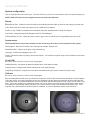
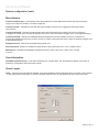
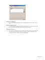
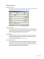
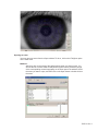
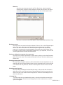
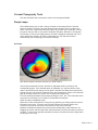
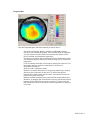
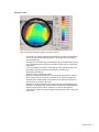
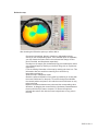
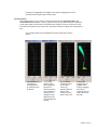
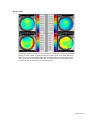
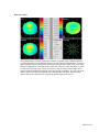
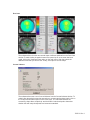
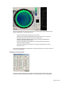
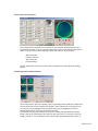
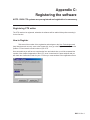
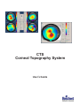
CTS
Corneal Topography System
User’s Guide
Introduction
Congratulations on the purchase of your new CTS Corneal Topography System.
The CTS software allows the visualization of the Axial, Tangential and Refractive maps in Normalized, Numeric, Absolute
and Adjustable scales, as well as an Elevation map. All the maps can be viewed in perspective using the three-dimensional
view option. It is also possible to see the cornea profiles of all mentioned maps. The incorporation of tools like Maps of
Differences, allows the comparison of corneal maps, which are extremely useful in the pre and post-surgical examination.
The CTS software also incorporates a program dedicated to the simulation of fluoroscopic images, useful for fitting PMMA
or RGP contact lenses of diverse design.
This User’s Guide is designed as a training and reference manual for operation, maintenance and troubleshooting. We
recommend that you read it carefully prior to use and follow the instructions in the guide to ensure optimum performance
of your new instrument.
Please retain this manual for future reference and to share with other users. Additional copies can be obtained from your
authorized Reichert dealer or from the Reichert Customer Service department. Contact information is provided at the end
of this guide.
CAUTION: IN ORDER TO ENSURE THAT CORRECT OPERATION OF THE CTS IS MAINTAINED, ANY REPAIR OR
SERVICE MUST BE PERFORMED BY EXPERIENCED PERSONNEL THAT ARE TRAINED BY REICHERT OPHTHALMIC
INSTRUMENTS.
CAUTION ESDS: THE INTERNAL CIRCUITRY OF THE CTS CONTAINS ELECTROSTATIC DISCHARGE SENSITIVE
DEVICES (ESDS). SUCH COMPONENTS MAY BE SENSITIVE TO HIGH VOLTAGES PRODUCED BY STATIC CHARGES
FROM THE HUMAN BODY. DO NOT REMOVE THE COVER OF THE CTS WITHOUT TAKING PROPER PRECAUTIONS
OR DAMAGE TO THE CTS MAY OCCUR.
CAUTION: DO NOT USE SOLVENTS OR STRONG CLEANING SOLUTIONS ON ANY PART OF THE CTS OR DAMAGE
TO THE UNIT MAY OCCUR.
WARNING: DO NOT REMOVE OR DEFEAT THE EARTH GROUND CONNECTION ON THE CTS POWER INPUT
CONNECTOR OR THE UNIT’S POWER CORD. DAMAGE TO THE CTS AND/OR INJURY TO THE OPERATOR MAY
OCCUR.
WARNING: THE CTS SHOULD BE USED IN STRICT ACCORDANCE WITH THE INSTRUCTIONS OUTLINED IN THIS
USERS GUIDE. THE SAFETY OF THE OPERATOR AND THE PERFORMANCE OF THE INSTRUMENT CANNOT BE
GUARANTEED IF USED IN A MANNER NOT SPECIFIED BY REICHERT OPHTHALMIC INSTRUMENTS.
WARNING: THE CTS CONTAINS A CLASS I LASER DEVICE. DO NOT TAMPER OR ATTEMPT TO REPAIR OR ADJUST
THIS DEVICE. IF REPAIR IS NECESSARY, CONTACT REICHERT IMMEDIATELY FOR SERVICE.
WARNING: THE CTS CONTAINS A CLASS I LASER DEVICE. DO NOT OPERATE THE LASER DEVICE CONTINOUSLY
FOR MORE THAN 100 SECONDS.
NOTE: THE INFORMATION IN THIS MANUAL IS SUBJECT TO CHANGE WITHOUT NOTICE.
15050-101-Rev. A
Package Contents
The items listed below should be included in the CTS packaging container(s). If any of these items are missing, please
contact Reichert Customer Service.
Catalog Numbers 15051 & 15053
•
CTS Topographer Head
•
CTS Power Control Unit
•
Insulated Transformer
•
Chinrest Assembly
•
Slide Shaft with 2 Pinion Caps
•
Table Top
•
Parallel Cable
•
Interface Cable
•
3 Power Cords
•
Test Eye
•
4 EMC Core
•
Spare Cone Cover
•
Dust Cover
•
2 Spare Fuses for Power Control Unit (attached)
•
2 Spare Fuses for Insulated Transformer (attached)
•
2 Rail Covers with screws
•
Chinrest paper
•
Belkin USB Capture Device
•
Video Cord Coupler
•
CTS Software on CD-Rom
•
Users Guide
Catalog Number 15050 only
•
CTS Topographer Head
•
Gateway Profile Computer with Mouse and Keyboard
•
Table Pedestal with castors
•
Table Power Cord
•
Fully Assembled Tabletop
•
Chinrest Assembly
•
Slide Shaft with 2 Pinion Caps
•
Test Eye
•
Quick Installation Guide
•
CTS Software on CD-Rom
•
User’s Guide
15050-101-Rev. A
Setup
NOTE: For Catalog Number 15050, please refer to your Quick Installation Guide for setup instructions.
Catalog Numbers 15051 & 15053
•
Computer System Requirements
•
PC compatible Pentium IV and CD-ROM drive
•
At least 256Mb. (Recommended 512Mb.)
•
1 Parallel, for CTS unit.
•
USB 2.0 port
•
Windows XP
Hardware Installation
1. Unpack the CTS unit.
2. Mount and fix the CTS base unit on the table.
3. Connect the supplied cables as shown below.
4. Connect the interface cable to the front of the topographer shown in red below to the CNTR port on the topographer
power supply unit.
5. Connect the Parallel Cable to the IEEE 1284 Connector on the back of the topographer power supply box and to the
parallel port on your computer.
6
Attach the Belkin DVD Capture Device to the VIDEO port on the back of the topographer power supply box and to an
open USB port on your PC.
7. Attach one of the supplied power cords from the back of the topographer power supply box to the Insulated Transformer
labeled CAPTURE.
8. Use the other two supplied power cords to attach your PC and monitor to the Insulated Transformer outlets labeled PC
and MONITOR.
9. Insert the chinrest assembly into the chinrest base on the table.
10. Connect a power cord to the back of the Insulated Transformer to a wall outlet.
15050-101-Rev. A
Installing the Software
1.) Insert the CTS CD Software into the CD-ROM drive.
2.) The Windows autorun feature will automatically bring up the CTS setup menu.
3.) Select Install Belkin F5U228 Drivers
4.) Follow the instructions provided by the installation wizard and select Finish when the
installation is complete.
5.) Select Install DirectX 9.0c
6.) Follow the instructions provided by the installation wizard and select Finish when the installation
is complete.
7.) Select Install CTS Software
8.) Follow the instructions provided by the installation wizard. We reccomend choosing the
Typical installation option which will provide you the most common options. Compact and
Custom should only be selected by advanced users.
9.) Select Finish when the installation is complete.
Now the CTS software is ready to use.
15050-101-Rev. A
Using the Software
System configuration
Click on Tools|Options on the main menu. If this is the first time you have run the software, refer to the System Setup item.
NOTE: 15050 CTS units are pre-configured and do not need to be calibrated.
Startup
Default/Mode-Type: Selects the action that will be automatically performed after an exam or after opening a stored case.
Units: Selects the unit in which the system will use. (Millimeters or Diopters)
Confirm on exit: Enables or disables the confirmation dialog box displayed before exiting the software.
Color Scale: Selects between Red->Magenta and Pink->Dark Magenta.
Numerical Map Full Color: Shows the power values in green color or with the color corresponding in the color scale.
System setup
NOTE: Modification of any of the parameters of this screen may cause the incorrect operation of the system.
Paths/Capture: Defines the location of the video capture software “dscap32.exe”.
Paths/Base folder: Defines the location of the base directory.
Language: Chooses the language for the CTS.
Printer: Defines the printer for printing screens and reports. You must have a printer setup on the computer for this option
to function.
Config HW
Be sure to connect and turn on the Corneal Topographer
Image/Brightness: Configures the default brightness level of the captured image.
Image/Contrast: Configures the default contrast level of the captured image.
Image/Rings Threshold: Configures the luminance threshold used by the system to detect the placido rings.
Calibrate
Be sure to connect and turn on the Corneal Topographer
Enter the calibration ball radii, which you will use to this process. Click the OK button and the calibration screen will appear.
Using the joystick, move the topographer close to the calibration ball and center the square box and the small white dot
in the small, center ring. When the white dot is near to the center area and the position is near center, you will hear a tone
beep. Move very carefully more towards the center until you will hear a more intense beep and hold the position steady.
The system will automatically capture and show you a screen with the image of the calibration ball and the rings. If the
rings are clear, please select OK and the system is calibrated. If you have problems, please contact Reichert.
15050-101-Rev. A
Using the Software
System configuration (cont.)
Miscellaneous
Contact Lens/Auto Save: Automatically saves the parameters of each adapted lens and its ensuing fluoroscopic
image in the Image File window, for further comparison.
Contact lens/Inter: Indicates the step with which the software will look for the suggested customized contact
lens (Custom).
Contact lens/Adjust: Indicates the approximate apical tear thickness that the software will use as a reference
to suggest the contact lens. Increase or decrease this value to have the software suggest more or less adjusted lenses.
Contact lens/Astig: Indicates an additional adjustment parameter that the software will use as a reference to
suggest the spherical contact lens over thoric cornea. Increase or decrease this value to have the software suggest more
or less adjusted lenses.
Background color: Defines the workspace background color.
File associations: Enables or disables the associations of the export files of the "*.exm" "software with it.
Maintenance: Schedules the database maintenance period. (Once a day, once a week, once a month
or never)
User Information
User/Name-Address-Phone: Fill in these fields with your company data. The information will appear in the footer in
printouts of Topographic and Fluoroscopic reports.
Views Layout
Views: Selects the items that will be available in the patient database window displayed when you create or edit a patient.
To select all the items click Reset. To select or deselect each item click on the square next to the name of the item.
15050-101-Rev. A
Managing the Database
Managing Groups:
You can access the group management option from the Options window. To do so, click
on View|Complementary Data on the main menu. Then choose Groups.
Entering a new group:
From the group management option, click Add, and then enter the name in the text box.
Editing the group name:
From the group management option click on the name of the group you want to edit, then
click the Edit button; finally enter the new name in the text box.
Removing a group:
From the group management option, click the name of the group you want to delete, and
then click on the Delete button. A dialog box will ask you about the destination of the
patients in that group. To finish, choose the desired option.
Managing Diagnosis:
You can access the group management option from the Options window. To do so, click
on View|Complementary Data on the main menu. Then choose Diagnosis.
15050-101-Rev. A
Entering a new diagnosis:
From the Diagnosis management option, click Add, and then enter the name in the text
box.
Editing the diagnosis name:
From the diagnosis management option click on the name of the group you want to edit,
then click the Edit button; finally enter the new name in the text box.
Removing a diagnosis:
From the group management option, click the name of the group you want to delete, and
then click on the Delete button. A dialog box will ask you about the destination of the
patients in that group. To finish, choose the desired option.
15050-101-Rev. A
Managing Patients
Entering a new patient:
You may enter a new patient from the new wi ndow. To do so, click on the File|New option
on the main menu. After that, fill in the fields with the patient's data.
Editing patient's data:
You may edit the patient's data from the New window. To do so, click on the File|New
option on the main menu. Then, click on the name of the patient whose data you wish to
edit. After that, press the keyboard Insert key, or click on the mouse’s right button and
choose Edit. Finally, edit the patient's fields from the Edit window.
You may also edit the patient's data from the Open window.
Deleting patients:
You may delete patient's data from the New window. To do so, click on the File|New
option on the main menu. After that, click on the name of the patient whose data you
want to eliminate. Then press the keyboard Delete key, or click on the mouse’s right
button and choose the Delete option.
You may also delete patient's data from the Open window.
Browsing patient's details:
You may browse patient's details from the New window. To do so, click on the File|New
option on the main menu. After that, click on the name of the patient whose data you
want to browse. Then click on the mouse’s right button and choose the View Details
option. The software allows you to print patient's data by clicking the Print button. To exit
the details window, press the Escape key in your keyboard.
You may also browse patient's details from the Open window.
15050-101-Rev. A
Managing Exams
Taking an exam:
From the New window, click on the patient’s name whom you wish to give an exam. After
that, choose the eye you wish to examine. Finally, click on the Exam button.
The Capture Window will then appear on your screen. Place the patient at equipment‘s
front, center the smallest rectangle with the image of the internal circle reflected on the
cornea and bring the equipment smoothly closer to the eye until the laser matches the
first two. When a condition near to focus has been achieved, the equipment will make a
sound that will become sharper when the focus condition is met. After this happens, the
software will automatically capture the image and will start the process to detect the
center, pupil and rings. If the software cannot detect the center automatically, you will
have to click on the center of the image of the internal ring. If the captured image is
unacceptable, click on the Retake button to repeat the capture. If the image of the rings is
too weak, click on the Reprocess button and adjust the brightness and contrast features
manually. Then click on the center of the image of the internal ring.
When the detected rings match the rings reflected on the cornea, click on the Ok button.
If you wish to take the image of the other eye, click on the Take L or Take R buttons
depending on whether you need to examine the left or the right eye, respectively, and
repeat the capture process. Otherwise, click on the finish button.
15050-101-Rev. A
Opening an exam:
You may open one exam from the Open window. To do so, click on the File|Open option
on the main menu.
Method 1:
After that, click on the name of the patient whose exam you want to open. You
will see the list of exams made to that patient together with a preliminary image
of the corresponding corneal topography on the lower part of the window. Select
the exam you want to open, and then click on the Open button or double click on
the exam.
15050-101-Rev. A
Method 2:
After that, type the text to search in the Text Search box, select the desired
Include option, the field to search and then click the Search button. The Search
results list will be filled select the desired item and then click the Open button.
After that, the selected window will appear in Options|Startup|Default/Mode-Type.
Deleting an exam:
You may remove an exam from the Open window. To do so, click on the File|Open option
on the main menu. After that, click on the patient’s name whose exam you want to
remove. You will see the exams list made to that patient together with a preliminary
image of the corresponding corneal topography on the lower part of the window. Select
the exam you want to remove, and press the Delete key in your keyboard, or click on the
mouse’s right button and choose the Delete option.
Viewing or editing the comments of an open exam:
You may view or edit the comments of an open exam by clicking on the View|Comments
option on the main menu. The comment window will be shown: write there whatever you
want to save.
Changing exam patient Owner
You may change the patient owner, to do this click with the mouse's right button over the
exam list and choose Change Patient Owner from the contextual menu, now you will see
a new window with the patient list. Select the desired patient name and click in the OK
button.
Changing exam diagnosis
You may change the diagnosis related with this exam, to do this click with the mouse's
right button over the exam list and choose Change Diagnosis from the contextual menu,
now you will see a new window with the diagnosis list. Select the desired diagnosis and
click in the OK button.
Changing Eye
You may change the eye related with this exam, to do this click with the mouse's right
button over the exam list and choose Change Eye from the contextual menu, now the
eye will be toggled.
15050-101-Rev. A
Corneal Topography Tools
This item describes how to access the various corneal maps available.
Simple maps:
The software allows you to view a variety of simple corneal maps from the Corneal
Structure window. To make it once the patient’s exam has been open or made a new
exam, click on the View|Corneal Structure option on the main menu. After that, click on
the type of map you wish to view (Axial, Tangential, Elevation, Refractive, 3D map and
3D Cornea), or click on the Graph button if you wish to display the selected map. If the
action selected by default is an Axial or Tangential map, the map will be shown
automatically (see Configuring your Software /Startup).
Axial map
After the Axial option has been selected, you will be able to:
Choose the Normalized, Numeric, Absolute or Adjustable scale by clicking on the
corresponding option. If the selected option is Adjustable, you may choose the mean
value in the scale and the change of color pitch in the Med. and Step boxes respectively.
Overlap over the map a grid, the detected rings, the Keratometrics values or the detected
pupil by checking on the Grid, Rings, Ker or Pupil boxes respectively.
Fill in the missing information of the map by clicking the Inter. box. This information does
not result from metering, but it is filled in by interpolation techniques.
Show the map in transparent mode.
Obtain the curvature and position of any point by positioning or clicking with the mouse’s
left button on the point. To remove the sign that indicates the corneal position and
curvature, click with the left button of the mouse on any point in the map.
Measure the distance between two points and the corresponding value difference, by
dragging the mouse with the right button pressed between the two points that you want to
compare. To remove the sign that indicates the values, click with the mouse’s right button
on any point in the map.
15050-101-Rev. A
Tangential Map
After the Tangential option has been selected you will be able to:
Choose the Normalized, Numeric, Absolute or Adjustable scale by
clicking on the corresponding option. If the selected option is Adjustable,
you may choose the mean value in the scale and the change of color
pitch in the Med. and Step boxes respectively.
Overlap over the map a grid, the detected rings, the Keratometric values
or the detected pupil by checking on the Grid; Rings; Ker or Pupil boxes
respectively.
Fill in the missing information of the map by checking the Inter box. This
information does not result from metering, but it is filled in by
interpolation techniques.
Show the map in transparent mode.
Obtain the curvature and position of any point by positioning or clicking
with the mouse’s left button on the point. To remove the sign that
indicates the corneal position and curvature, click with the mouse’s left
button on any point in the map.
Measure the distance between two points and the corresponding value
difference, by dragging the mouse with the mouse’s right button pressed
between the two points that you want to compare. To remove the sign
that indicates the values, click with the mouse’s right button on any point
in the map
15050-101-Rev. A
Elevations map
After choosing the Elevation option you will be able to:
Choose the curvature of the sphere with which you wish to compare the
cornea, as well as the relative position of its vertices from the R and Z
boxes respectively.
Overlap over the map a grid, the detected rings, the Keratometric values
or the detected pupil by checking on the Grid; Rings, Ker or Pupil boxes
respectively.
Fill in the missing information of the map by clicking the word Inter. This
information does not result from metering, but it is filled in by
interpolation techniques.
Show the map in transparent mode.
Obtain the elevation and position of any point by positioning or clicking
with the left button of the mouse on the point. To remove the sign that
indicates the corneal position and elevation, click with the left button of
the mouse on any point in the map.
Measure the distance between two points and the corresponding value
difference, by dragging the mouse with the right button pressed between
the two points that you want to compare. To remove the sign that
indicates the values, click with the right button of the mouse on any point
in the map.
15050-101-Rev. A
Refractive map
After choosing the Refractive option you will be able to:
Choose the Normalized, Numeric, Absolute or Adjustable scale by
clicking on the corresponding option. If the selected option is Adjustable,
you may choose the mean value in the scale and the change of color
pitch in the Med. and Step boxes respectively.
Overlap over the map a grid, the detected rings, the Keratometric values
or the detected pupil by checking on the Grid, Rings, Ker or Pupil boxes
respectively.
Fill in the missing information of the map by checking the Inter. box. This
information does not result from metering, but it is filled in by
interpolation techniques.
Show the map in transparent mode.
Obtain the power and position of any point by positioning or clicking with
the mouse’s left button on the point. To remove the sign that indicates
the corneal position and power, click with the mouse’s left button on any
point in the map.
Measure the distance between two points and the corresponding value
difference, by dragging the mouse with the right button pressed between
the two points that you want to compare. To remove the sign that
indicates the values, click with the mouse’s right button on any point in
the map.
15050-101-Rev. A
3D maps
After choosing the 3D Maps option you will be able to:
Choose the type of map you wish to view in this mode by clicking on the
word 3DAxial, 3DTangential, 3DElevation and 3DRefractive respectively.
Change the perspective angle by dragging the mouse both vertically and
horizontally with the left button over the map.
Change the exaggeration of heights of the map by dragging the mouse
vertically with the right button over the map.
3D cornea representation
After choosing the 3D Cornea you will be able to:
Change the perspective angle by dragging the mouse both vertically and
horizontally with the left button over the map.
15050-101-Rev. A
Change the exaggeration of heights of the map by dragging the mouse
vertically with the right button over the map.
Corneal profiles:
The software allows view a variety of corneal profiles from the Corneal Profiles and
Corneal Structure windows. To do so, after the exam of one patient has been opened or
a new exam made, and with the Corneal Structure window on screen, click on the View
|Corneal Profile option on the main menu. Once this window is viewed, you will be able to
see:
The corneal profiles in the keratometric axes by clicking the Sim k's
button.
The difference of
keratometric
corneal profiles
by clicking on the
dk button.
The corneal
profiles of the
axial, tangential,
elevation or
refractive map, in
any meridian, by
clicking on the
respective map
displayed in the
Corneal Structure
window
The curvature,
refractive power
or elevation
values, by
pressing the left
button of the
mouse over any
point in the curve
Change the
exaggeration of
heights of the
map by dragging
the mouse
vertically with the
right button over
the map
.
15050-101-Rev. A
Multiple maps
The software allows view the four corneal maps simultaneously from the Multiple Maps
window. To make it after the patient's exam has opened up or a new exam has been
made, click on the View|Multiple Maps option on the main menu. By pressing the left
button of the mouse over the several maps, you will be able to see the position and
curvature, power or elevation of any point in the map.
15050-101-Rev. A
Difference maps
The software allows view the comparison between to corneal maps of different patients
or of the same patient in two different stages from the Difference Map window. To make it
after the patient's exam has opened up or a new exam has been made, click on the View
|Difference Map option on the main menu. After that, select the exam with which you wish
to compare the current exam. Finally, click Open to see the maps of each exam on the
upper area and the difference maps on the lower area of the window. You may choose to
see the maps in the axial or tangential mode with different color pitch, and to see the
value of the curve or difference in any point by positioning the mouse on it.
15050-101-Rev. A
Dual case
The software allows view the two corneal maps of different patients from the Dual Case
window. To make it after the patient's exam has opened up or a new exam has been
made, click on the View|Dual Case option on the main menu. After that, select the
additional exam that you wish to see. Finally, click Open to see the maps.
Corneal indexes
The software allows see a set of corneal indexes from the Corneal Indexes window. To
make it after the patient's exam has opened up or a new exam has been made, click on
the Tools|Corneal Indexes option on the main menu. The calculated indexes are:
eccentricity, shape factor, asphericity and the KISA% index developed to determine
whether the axial map corresponds to a keratocone standard.
15050-101-Rev. A
Eye view
The software allows view, measure and edit the pupil shape, click on the View|Eye option
on the main menu.
Printing a topographic report
The software allows print a topographic report that shows the topographic map displayed,
the corneal profiles and the image of the patient's eye with the detected rings. To do so,
and with the Corneal Structure window open, click on the File|Print|Topographic Report
option on the main menu.
Printing a dual topographic report
The software allows you to print a dual topographic report. To do so, and with the Dual
Case window open, click on the File|Print|Dual Topographic Report option on the main
menu.
15050-101-Rev. A
Contact lens tools
This part will describe how to obtain the parameters of a contact lens suggested by the
software and see the fluoroscopic image of the lens on the cornea.
Obtaining a suggested lens
The software allows you to obtain a suggested lens from the Suggested Lens window. To
make it after the patient's exam has opened up or a new exam has been made, click on
the Tools|Contact Lenses|Suggest option on the ma in menu. After that, fill in the following
fields: Dia (total lens diameter), VD (distance to vertex), Sph (spherical patient refraction),
Cyl (cylindrical patient refraction), and Axis (axis of the cylindrical refraction). Then, you
will be able to choose between a customized lens and a pre-existing lens.
Custom lens
After completing the diameter and refraction data, select the Custom option in the Lens
type box. After that, select the shape of the lens you want to obtain from the following
geometries: Spherical, Toric, Aspheric and Atoric. Finally, click on the Suggest Lens
button.
Pre-existing lens
After completing the diameter and refraction data, select the type of lens you wish
between PMMA Hard Lens and Rigid Gas Permeable in the Lens type box. Then select
the shape of the lens you want to obtain from the following geometries: Spherical, Toric,
Aspheric and Atoric. Click then on the Suggest brand button. A lenses list of each
manufacturer that match the required conditions will be displayed on the screen. Select
the most suitable option and finally click the Suggest Lens button.
15050-101-Rev. A
After the suggested lens has been calculated, the Fluoroscopic image window will be
shown on the screen. This will allow you to:
See the fluoroscopic lens image over the cornea.
Measure the tear thickness between the lens and the cornea in any point
by pressing the left button of the mouse over the point.
Measure the distance between two points by clicking and dragging the
mouse’s right button between them.
See the tear profile in any meridian, by clicking the fluoroscopic image
with the l mouse’s left button.
See the tear thickness in any point of the profile by pressing the mouse’s
left button over it.
This window also displays the keratometric values and the base curve of the lens BC in
the two main meridians.
Changing the lens parameters.
You may view the parameters of a contact lens displayed in the Fluoroscopic Image
window form the Lens Parameters window. To do so, and while you are viewing the
15050-101-Rev. A
simulated fluoroscopic image, click on the View |Lens Parameters option on the main
menu. The following lens parameters will appear in that window:
BC(i) Base curve of the main meridians (i = 1; 2)
P(i)
Power of the main meridians (i = 1; 2)
QBC Asphericity of the base curve
PC(i) Intermediate and Peripheral Curves (i = 1; 2; 3; 4)
WPC(i) Width of Intermediate and Peripheral Curves (i = 1; 2; 3; 4)
QPC(i) Asphericity of Intermediate and Peripheral Curves (i = 1; 2; 3; 4)
Dia
Total diameter
OZ
Diameter of the optical zone
Shape Geometry
From this window you may modify any parameter, after which the software will draw the
fluoroscopic image corresponding to that modification.
Repositioning the lens
The software allows reposition the lens on the cornea from the Lens Parameters window.
By clicking on the Reposition>> button, a set of additional data and controls will be
displayed. Click on the arrows next to the Y to change the vertical position, or on the
arrows next to the X to change the horizontal position of the lens.
The additional information available will be:
X Indicates the horizontal displacement of the lens against the center of the cornea.
Y Indicates the vertical displacement of the lens against the center of the cornea.
Indicates the radial coordinate of the center of the lens against the center of the cornea.
Indicates the angular coordinate of the center of the lens against the center of the cornea.
Indicates the displacement pitch.
To reposition the lens to its original place, click Reset button.
15050-101-Rev. A
Viewing the lens movement
The software allows view the lens movement on the eye while blinking from the Lens
Parameters windows. To do so, click the Reposition>> button and then the Movement>>
button. A set of controls will be displayed, which will allow you to (clockwise):
Start movement
Pause movement
Stop movement
Frame advance
Finally, under those controls, you will be able to regulate movement speed by clicking
Speed.
Comparing various adapted lenses
The first six times a new lens is drawn in the Fluoroscopic Image window, the data in the
window will be stored in the Images File window. This will allow you to compare in just
one view the various adaptations and go back to a previous adaptation for a more
detailed inspection in the Fluoroscopic Image window.
To access the Images File window, while you are viewing the simulated fluoroscopic
image, click on the View|Image Files option on the main menu. To select one of the six
images, click on it. The parameters of the selected lens will be automatically shown. If
15050-101-Rev. A
you wish to store the lens displayed in the Fluoroscopic Image in the selected place, click
on the Save button. If you wish to have a more detailed inspection of the selected lens,
click Open. Thus, the image will be transferred to the Fluoroscopic Image window.
Images stored in the Images File window will be erased after the Fluoroscopic Image is
hidden.
Printing a fluoroscopic report
The software allows you to print a fluoroscopic report with all the data of the adaptation.
To do so, and with the Fluoroscopic Image open, click on the File |Prin|Fit simulation
report option on the main menu.
15050-101-Rev. A
Appendix A:
Technical specification
Equipment Type: Type B Class I Equipment, Continous Operation
Performance:
Maximum Coverage Area .................................10.6mm (@7.85mm radii)
Measurement Range ....................................................................... 9-99D
Accuracy ................................................................................... +/- 0.125D
Measurement Technology ............................................ Placido Rings (20)
Measurement Points ......................................................................... 6344
Alignment Device .................................................................. LCD Monitor
Alignment Method .................................................. Class I Laser (670nm)
Voltage ....................................................................... 100-120VAC, 60Hz
Consumption ....................................................................................30VA
Transportation & Storage Conditions
This instrument can withstand the following conditions while packed for
transportation or storage:
•
•
•
an ambient temperature range of -20°C (-4°F) to +70°C (158°F)
a relative humidity range of 10% to 90%
an atmospheric pressure range of 55 kPa to 106 kPa
Exposure to extreme environmental conditions indicated above
must not exceed 6 days.
Operational Conditions
This instrument can withstand the following conditions while in daily use:
•
•
•
an ambient temperature range of 10°C (50°F) to 43°C (110°F)
a relative humidity range of 10% to 90%
an atmospheric pressure range of 55 kPa to 106 kPa
WARNING!
Avoid the following conditions for storage and use:
• Noxious gases or air pollutants
• Dust and grit
• Oil fumes or greasy substances
• Atmospheric concentrations of salt
• Unstable areas or areas of strong vibrations or sudden shocks
• Inclinations of more than 10 degrees
• Voltage from power sources that rise or fall sharply during loading
• Fluctuations in voltage of the power source
• Direct contact with sunlight
• Atmospheric concentrations of salt
• Unstable areas or areas of strong vibrations or sudden shocks
• At an inclination of more than 10 degrees
15050-101-Rev. A
Appendix B:
Licenses
SOFTWARE LICENSE AGREEMENT
Reichert Inc. grants you a non-exclusive, non-transferable license to use this copy of the
program and accompanying documentation according to the following terms.
LICENSE
Customer may run the CTS software on only one Corneal Topographer Device.
Customer may not to use the program on more than one Corneal Topographer and/or
computer. Customer may not modify, tr anslate, reverse-engineer, decompile,
disassemble or otherwise attempt to derive or modify the source code. Reichert Inc.
reserves all rights and licenses not expressly granted to Customer.
15050-101-Rev. A
Appendix C:
Registering the software
NOTE: 15050 CTS systems are pre-registered and registration is unecessary.
Registering CTS online
The CTS needs to be registered; otherwise the software will be usable 30 days after executing it
for the first time.
How to Register
Take note of the number of the registration and navigate to the Kern Technologies web
(http://www.kerntech.com.ar), enter to the Support link, then go to the Registration link, select the
product CTS and enter the serial number of your CTS.
Once entered that you will have to complete the form and submit then you will be requested the
number of the obtained registration of their CTS, once it introduced, the press subjects and you
will obtain the Confirmation Code for your CTS then you must annotate in the registration screen.
15050-101-Rev.
A
44
Warranty
This product is warranted by Reichert, Inc. (herein after referred to as Reichert) against defective material and
workmanship under normal use for a period of one year from the date of invoice to the original purchaser. (An authorized
dealer shall not be considered an original purchaser.) Under this warranty, Reichert’s sole obligation is to repair or replace
the defective part or product at Reichert’s discretion.
This warranty applies to new products and does not apply to a product that has been tampered with, altered in any
way, misused, damaged by accident or negligence, or which has had the serial number removed, altered or effaced. Nor
shall this warranty be extended to a product installed or operated in a manner not in accordance with the applicable Reichert
instruction manual, nor to a product which has been sold, serviced, installed or repaired other than by a Reichert factory,
Technical Service Center, or authorized Reichert Dealer.
Lamps, bulbs, charts, cards and other expendable items are not covered by this warranty.
All claims under this warranty must be in writing and directed to the Reichert factory, Technical Service Center, or
authorized instrument dealer making the original sale and must be accompanied by a copy of the purchaser’s invoice.
This warranty is in lieu of all other warranties implied or expressed. All implied warranties of merchantability or fitness
for a particular use are hereby disclaimed. No representative or other person is authorized to make any other obligations
for Reichert. Reichert shall not be liable for any special, incidental, or consequent damages for any negligence, breach
of warranty, strict liability or any other damages resulting from or relating to design, manufacture, sale, use or handling of
the product.
PATENT WARRANTY
If notified promptly in writing of any action brought against the purchaser based on a claim that the instrument infringes
a U.S. Patent, Reichert will defend such action at its expense and will pay costs and damages awarded in any such action,
provided that Reichert shall have sole control of the defense of any such action with information and assistance (at Reichert’s
expense) for such defense, and of all negotiation for the settlement and compromise thereof.
PRODUCT CHANGES
Reichert reserves the right to make changes in design or to make additions to or improvements in its products without
obligation to add such to products previously manufactured.
CLAIMS FOR SHORTAGES
We use extreme care in selection, checking, rechecking and packing to eliminate the possibility of error. If any shipping
errors are discovered:
1. Carefully go through the packing materials to be sure nothing was
inadvertently overlooked when the unit was unpacked.
2. Call the dealer you purchased the product from and report the
shortage. The materials are packed at the factory and none
should be missing if the box has never been opened.
3. Claims must be filed within 30 days of purchase.
CLAIMS FOR DAMAGES IN TRANSIT
Our shipping responsibility ceases with the safe delivery in good condition to the transportation company. Claims
for loss or damage in transit should be made promptly and directly to the transportation company.
If, upon delivery, the outside of the packing case shows evidence of rough handling or damage, the transportation
company’s agent should be requested to make a “Received in Bad Order” notation on the delivery receipt. If within 48
hours of delivery, concealed damage is noted upon unpacking the shipment and no exterior evidence of rough handling
is apparent, the transportation company should be requested to make out a “Bad Order” report. This procedure is necessary
in order for the dealer to maintain the right of recovery from the carrier.
15050-101-Rev. A
Reichert Ophthalmic Instruments
Reichert, Inc.
3374 Walden Ave
Depew, NY 14043
USA
Toll Free: 888-849-8955
Phone: 716-686-4500
email: [email protected]
www.reichert.com
Reichert GmbH
Hubertusstrasse 2
D-82229 Seefeld
Germany
Tel: +49-8152-993530
ISO-9001 Certified