1
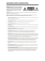
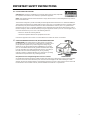
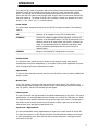
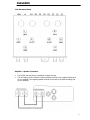
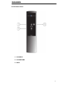
o o o o o o o o o o o o o o o o o o o o o o o o o o o o o o o o o o o o o o o o o o o o o o o o o o o o o o o o o o o o o o o o o o o o o o o o o o o o o o o o o o o o
OWNER’S MANUAL
o o o o o o o o o o o o o o o o o o o o o o o o o o o o o o o o o o o o o o o o o o o o o o o o o o o o o o o o o o o o o o o o o o o o o o o o o o o o o o o o o o o o
SLP 98
Vacuum Tube Preamplifier
NOTE: Before installing your new component, please read this manual
carefully as it will inform you of the product specifications, proper
installation and correct operating procedures for your unit. Also included
in this manual are guidelines on how to service and care for your new
Cary Audio Design product.
TABLE OF CONTENTS
Important Safety Instructions ...................................................................................................................... 2
Specifications ................................................................................................................................................ 5
Features ......................................................................................................................................................... 7
Installation
Unpacking .................................................................................................................................................... 8
Warranty Card .............................................................................................................................................. 8
Placement .................................................................................................................................................... 8
Power Requirements ...................................................................................................................................... 8
Cables .......................................................................................................................................................... 8
Operation
Power Switch ................................................................................................................................................ 9
Selector Switch ............................................................................................................................................. 9
Operate Mode ............................................................................................................................................... 9
Monitor Tape ................................................................................................................................................ 9
Listening Level .............................................................................................................................................. 9
Input Level ................................................................................................................................................... 9
Service and Care
Tube Replacement........................................................................................................................................10
Factory Service ............................................................................................................................................10
Non-Warranty Repairs...................................................................................................................................10
Diagrams
Tube Placement Cart ....................................................................................................................................11
Amplifier-Speaker Connection ........................................................................................................................11
RC-10 Remote Control ..................................................................................................................................12
Limited Warranty..........................................................................................................................................13
IMPORTANT SAFETY INSTRUCTIONS
WARNING: To reduce the risk of fire or electric shock, do
not expose this appliance to rain or moisture. The lightning
flash with arrowhead symbol within an equilateral triangle is
intended to alert the user to the presence of un-insulated
dangerous voltage within the product’s enclosure that may
be of sufficient magnitude to constitute a risk of electric
shock to persons.
CAUTION: To reduce the risk of electric shock, do not remove the cover. There are no user serviceable parts inside.
Please refer to qualified personnel for service.
ALERT: The exclamation point within an equilateral triangle is intended to alert the user of the presence of important
operating and maintenance (servicing) instructions in the literature accompanying the component.
1.
READ ALL INSTRUCTIONS: All the safety and operating instructions of your Cary Audio equipment should be read
before power is applied to the equipment.
2.
RETAIN OWNER'S MANUAL: These safety and operating instructions should be retained for future reference.
3.
HEED WARNING: All warnings on the unit and in the operating instructions should be adhered to.
4.
FOLLOW INSTRUCTIONS: All operating and use instructions should be followed.
5.
CLEANING: Unplug the unit from the wall outlet before cleaning. The unit should be cleaned only as recommended
by the manufacturer.
6.
ATTACHMENTS: Do not use attachments not recommended by the unit manufacturer as they may cause hazards.
7.
WATER AND MOISTURE: Do not use the unit near water - for example, near a bath tub, wash bowl, kitchen sink,
or laundry tub; in a wet basement; or near a swimming pool.
8.
ACCESSORIES: Do not place the unit on an unstable cart, stand, tripod, bracket, or table. The unit may fall,
causing serious injury to a child, an adult, or damage to the unit. Mounting of the unit should follow the
manufacturer's instructions and should use a mounting accessory recommended by the manufacturer.
9.
VENTILATION: Slots and openings in the cabinet are provided for ventilation to ensure reliable operation of the
unit and to protect it from overheating. These openings must not be blocked or covered. The top or bottom panel
openings should never be blocked by placing the unit on a bed, sofa, rug, or other similar surface. The unit should
not be installed in a built-in location such as a bookcase or rack unless proper ventilation is provided. There should
be free space of at least 6 inches (16cm) above the unit and an opening behind the unit.
10. GROUNDING OR POLARIZATION: The unit may be equipped with a polarized alternating current line plug (a plug
having one blade wider than the other). This plug will fit into the power outlet only one way. This is a safety feature.
If you cannot insert the plug fully into the outlet, try reversing the plug. If the plug should fail to fit, contact a
licensed electrician to replace your obsolete outlet. Do not defeat the safety purpose of the polarized plug.
11. POWER SOURCES: The unit should be operated only from the type of power source indicated on the marking
label. If you are not sure of the type of power supplied to your home, consult your unit dealer or local power
company.
12. POWER CORD PROTECTION: Power supply cords should be routed so that they are unlikely to be walked on or
pinched by items placed on or against them. Pay close attention to cords where they enter a plug, or a convenience
receptacle, and the point where they exit from the unit.
13. OUTDOOR ANTENNA GROUNDING: If an outside antenna or cable system is connected to the unit, be sure the
antenna or cable system is grounded so as to provide protection against voltage surges and built-up static charges.
Article 810 of the National Electrical Code, NSI/NFPA 70, provides information regarding proper grounding of the
mast and supporting structure, grounding of the lead-in wire to an Antenna-discharge unit, size of grounding
conductors, location of antenna-discharge unit, connection to grounding electrodes, and requirements for the
grounding electrode.
2
IMPORTANT SAFETY INSTRUCTIONS
14. LIGHTNING: For added protection for the unit during a lightning storm, or when it is left unattended and unused for
long periods of time, unplug it from the wall outlet and disconnect the antenna or cable system. This will prevent
damage to the unit due to lightning and power line surges.
15. POWER LINES: An outside antenna system should not be located in the vicinity of overhead power lines or other
electric light or power circuits, or where it can fall into such power lines or circuits. When installing an outside antenna
system, take extreme care to keep from touching such power lines or circuits as contact with them might be fatal.
16. OVERLOADING: Do not overload wall outlets, extension cords, or integral convenience receptacles as this can
result in a risk of fire or electric shock.
17. OBJECT AND LIQUID ENTRY: Never push objects of any kind into the unit through openings as they may touch
dangerous voltage points or short-out parts that could result in a fire or electric shock. Never spill liquid of any kind
on the unit.
18. SERVICING: Do not attempt to service the unit yourself as opening or removing covers may expose you to
dangerous voltage or other hazards. Refer all servicing to qualified service personnel.
19. REPLACEMENT PARTS: When replacement parts are required, be sure the service technician has used
replacement parts specified by the manufacturer or have the same characteristics as the original part. Unauthorized
substitutions may result in fire, electric shock or other hazards.
20. SAFETY CHECK: Upon completion of any service or repairs to the unit, ask the service technician to perform safety
checks to determine that the unit is in proper operating condition.
21. WALL OR CEILING MOUNTING: The unit should be mounted to a wall or ceiling only as recommended by the
manufacturer.
22. HEAT: The unit should be situated away from heat sources such as radiators, heat registers, stoves, or other units
(including amplifiers) that produce heat.
23. IMPORTANT SAFETY NOTE: Before connecting a new component such as the DVD 7 to your audio or home
theater system it is always good practice to make certain that all components are turned off, and preferably
unplugged from their AC power source. Many modern electronics products feature automatic turn-on circuits that
may be activated during an installation, causing the potential for damage to electronic components and/or speakers.
Such damage is not covered by product warranties and Cary Audio specifically disclaims responsibility for any such
damage.
Power Cord: The removable power cord that is shipped with the player is specifically designed to be used with this
product. Other AC cords may be used, so consult your dealer for advice on AC power cords and high quality wire in
your system.
AC Fuse: The fuse is located inside the chassis and is not user serviceable. If power does not
come on, contact your authorized service representative.
Wiring: Cables that run inside of walls should have the appropriate markings to indicate compliance with, and listing
by the UL, CSA or other standards required by the UL, CSA, NEC or your local building code. Questions about cables
inside of walls should be referred to a qualified custom installer, or a licensed electrician or low-voltage contractor.
Do Not Open the Cabinet: There are no user serviceable components inside this product. Opening the cabinet
may present a shock hazard, and any modification to the product will void your warranty. If water or any metal
object, such as a paper clip, coin, or staple accidentally falls inside the unit, disconnect it from the AC power source
immediately and contact Cary Audio for further instructions.
24. RECORDING COPYRIGHT: Recording of copyrighted material for other than personal use is illegal without
permission of the copyright holder.
25. NOTE TO CATV SYSTEM INSTALLER: This reminder is provided to call the CATV system installer's attention to
article 820-40 of the NEC, ANSI/NFPA 70, which provides guidelines for proper grounding and, in particular, specifies
that the cable ground shall be connected to the grounding system of the building, as close to the point of cable entry
as practical.
3
IMPORTANT SAFETY INSTRUCTIONS
26. FCC INFORMATION FOR USER:
CAUTION: ANY changes or modifications not expressly approved by the party responsible
for compliance could void the user's authority to operate the equipment.
NOTE: This equipment has been tested and found to comply with the limits for a Class B digital device pursuant to
Part 15 of the FCC Rules.
These limits are designed to provide reasonable protection against harmful interference in a residential installation.
This equipment generates and can radiate radio frequency energy and, if not installed and used in accordance with
the instructions, may cause harmful interference to radio communications. However, there is no guarantee that
interference will not occur in a particular installation. If this equipment does cause harmful interference to radio or
television reception, which can be determined by turning the equipment off and on, the user is encouraged to try to
correct the interference by one or more of the following measures:
- Reorient or relocate the receiving antenna.
- Increase the separation between the equipment and receiver.
Connect the equipment into an outlet on a circuit different from where the receiver is connected.
27.
OUTDOOR ANTENNA INSTALLATION/SAFE ANTENNA AND CABLE
CONNECTION: If an outside antenna or cable system is connected to
the equipment, be sure the antenna or cable system is grounded so as to
provide protection against built up static charges and voltage surges,
Section 810 of the national Electrical Code, ANSI/NFP A70 (in Canada,
part 1 of the Canadian Electrical Code) provides information with respect
to proper grounding of the mast and supporting structure, grounding of
the lead-in wire to an antenna discharge unit, size of grounding
conductors, location of antenna discharge unit, connection to grounding
electrodes and requirements for the grounding electrode.
Keep Antenna Clear of High Voltage Power Lines or Circuits
An outside antenna system should be located well away from power lines, electric light or power circuits and where
it will never come into contact with these power sources if it should happen to fall. When installing an outside
antenna, extreme care should be taken to avoid touching power lines, circuits or other power sources as this could
be fatal. Because of the hazards involved, antenna installation should be left to a professional.
4
SPECIFICATIONS
This section describes the basic specifications of the SLP 98 preamplifier at the time of printing.
Specifications are subject to change without notice or obligation. When the following cautionary terms
are used in this manual, these definitions apply:
WARNING
• Electrical hazard! Misuse or failure to follow instructions properly may result in personal
injury or death!
CAUTION
• No risk or personal injury; however, misuse or failure to follow instructions may result
in damage to equipment.
NOTE
• No risk of personal injury or equipment damage; however, misuse or failure to follow
instructions may prevent proper performance of the equipment.
........................................................................................................................................................
CIRCUIT
Class A Triode
........................................................................................................................................................
INPUT IMPEDANCE
47,000 ohms phono section with user option on lower resistance
........................................................................................................................................................
OUTPUT IMPEDANCE
800 ohms
........................................................................................................................................................
GAIN
1.2 millivolt input = 1 volt output phono stage = 43 dB
110 millivolt input = 1 volt output line stage = 20 dB
........................................................................................................................................................
RIAA CURVE
1,000Hz = 0dB
20Hz = +20dB
20,000Hz = - 20.5 dB
........................................................................................................................................................
SIGNAL/NOISE RATIO
-88 dB
........................................................................................................................................................
RESISTORS
1% metal film
........................................................................................................................................................
CAPACITORS
Polystyrene and polypropylene
........................................................................................................................................................
POWER TRANSFORMER
200% duty cycle on all transformers enclosed in separate power
pack
........................................................................................................................................................
TUBES
2 - 6SN7 buffer cathode followers
2 - 6SN7 line stage
2 - 12AX7 (ECC83) phono section
2 - 12AU7 (ECC82) phono section output buffer
........................................................................................................................................................
POWER SUPPLY
Full wave rectification, center-tapped, pi-network featuring a filter
choke
........................................................................................................................................................
AC POWER REQUIREMENTS
100/130 volts AC @ 50/60Hz
200/245 volts AC @ 50/60Hz
........................................................................................................................................................
WIRE
EE Teflon Silver
.......................................................................................................................................................
5
SPECIFICATIONS
INPUT AND OUTPUT JACKS
Gold plated with Teflon® insert
........................................................................................................................................................
DUTY CYCLE
Continuous duty all modes 24 hours per day
........................................................................................................................................................
WARM-UP TIME
5 minutes
........................................................................................................................................................
BREAK IN TIME
100 hours of playing time
........................................................................................................................................................
DIMENSIONS
5” H x 12.5” W x 12” D
........................................................................................................................................................
WEIGHT
22 lbs.
........................................................................................................................................................
6
FEATURES
Front Panel
............................................................................................................................................
POWER OFF SWITCH
Rotary 3 position: off, stand-by, operate
............................................................................................................................................
SELECTOR
5 Position rotary switch controlling input selection
............................................................................................................................................
LEFT BLUE LED
Indicates AC power “ON”
............................................................................................................................................
OPERATE MUTE
Mutes output of preamplifier
............................................................................................................................................
TAPE MONITOR
By-passes all inputs to activate incoming tape recorder
signals
............................................................................................................................................
RIGHT BLUE LED
Indicates SLP 98 in tape monitor function
............................................................................................................................................
LISTENING LEVEL
Master dual volume control equally controlling input signal
to line section preamplifier
............................................................................................................................................
INPUT LEVEL LEFT
Individual control of left channel level feeding to master
listening level volume control
............................................................................................................................................
INPUT LEVEL RIGHT
Individual control of right channel level feeding to master
listening level volume control
............................................................................................................................................
Rear Apron
............................................................................................................................................
PHONO
These jacks are to be used with moving magnet or high
output moving coil cartridges with a recommended
minimum output of 1.4 millivolts
............................................................................................................................................
AUX.-CD-TUNER-TAPE
These are line level inputs
............................................................................................................................................
GND
Ground lug for turntable chassis
............................................................................................................................................
MONITOR
For use with tape recorders that employ a third head to
monitor a tape as it is being recorded (may be used as a
flat frequency response line input)
............................................................................................................................................
TAPE OUT
Constant output of selected input signal for recording
independent of volume control setting on SLP 98
............................................................................................................................................
DUAL OUTPUTS
1-Connect directly to input of power amps
............................................................................................................................................
AC
Multi-conductor power cord to be plugged into SLP 98
external power pack
............................................................................................................................................
CAUTION
• NEVER REMOVE / INSERT AC LINE CORD WHEN THE UNIT IS ON.
7
INSTALLATION
This section describes the unpacking and installation procedures for your new component.
WARNING
• MAKE NO ATTEMPT TO PUT THE AMPLIFIER IN SERVICE WITHOUT THE BOTTOM
PLATE ATTACHED - CONTACT WITH VOLTAGE IN THE SLP 98 CAN BE FATAL.
Unpacking
All Cary Audio Design shipping containers have been specially designed to protect their
contents and special care has been taken to prevent damage under normal shipping conditions.
Mishandling should be evident upon inspection of the shipping container. If shipping damage is
found after visual inspection, take care not to destroy the evidence. If necessary, document the
damage with photographs and contact the transport carrier immediately.
Carefully remove your new component from its packing carton and examine it closely for signs
of shipping damage. We strongly recommend saving all original packing cartons to protect your
amplifier from damage should you wish to store it or ship it for after-sales service.
Warranty Card
IN THE USA: If you are the original purchaser of a new unit from an AUTHORIZED CARY
AUDIO DESIGN DEALER, please fill out the enclosed warranty registration card and return it to
Cary Audio Design within 15 days of your purchase. Cary Audio Design also suggests that you
keep your original packing cartons in case you ever need to ship the unit when moving to a new
home. Warranty restrictions apply. Consult the warranty section at the end of this manual for
details. Please be certain to keep a copy of the original sales receipt from your AUTHORIZED
CARY AUDIO DESIGN DEALER to validate the warranty if ever needed. The warranty is for the
original purchaser only and does not transfer to any subsequent owner.
OUTSIDE THE USA: Your local Authorized Cary Audio Design Distributor will make his own
warranty policy for your country. Please check with them for the terms of warranty for your new
amplifier.
Placement
The SLP 98 is designed for use inside homes. It must be protected from the elements and
temperature extremes. For example, avoid placing the unit in extremely hot locations such as
near radiators or other heating units. Its location among the user’s audio components is not
critical; however, certain precautions must be taken.
Power Requirements
The SLP 98 is designed to operate from house current mains. The design voltage is 117 VAC at
50/60Hz (Foreign units 234 VAC at 50/60Hz).
Cables
The interconnect cables from the output jacks of the SLP 98 to the input jacks on the basic
amplifiers can be any convenient length your set-up requires. The choice of a high quality
interconnect cable is important. Most audio dealers will have proper speaker cable in stock for
this purpose.
8
OPERATION
Your new SLP 98 is ready for operation after all the tubes and interconnect cables have been
installed. The SLP 98 is provided with functional, useful front panel controls with a logical
layout. The listening level is conveniently located in the center. Connect the SLP 98 to the
power pack with the custom power transfer cable. Plug AC mains into the power pack and flip
the power switch up. The output of the SLP 98 is inverting. Connect your speaker wire out of
phase ( (+) to (-) and (-) to (+) ) on both channels.
Power Switch
The power switch located at the far left on the SLP 98 front panel functions in the following
manner:
............................................................................................................................................
OFF
Removes all AC voltages from the SLP 98 preamp deck.
............................................................................................................................................
STAND-BY
Provides DC voltage through individual regulators to flow to the
filaments of the preamplifier stage. (The SLP 98 may be left in the
stand-by position at all times to keep the SLP 98 in a warmed-up,
ready- to operate mode without B+ potential. Operating in this
fashion gives peak performance after only a few minutes of
operating time).
............................................................................................................................................
OPERATE
Brings up full potential DC voltage within one minute.
............................................................................................................................................
Selector Switch
The 5-position rotary switch connects a choice of input program source, both channels
simultaneously with proper amplification (or in the case of phono) RIAA equalization for phono
input. All program sources are selected by this switch.
Operate Mode
To listen to music the operate switch must be in the UP position; when the switch is DOWN the
output is muted.
Monitor Tape
In the “Up” position, the rear monitor jack serves as the input source. This function is very
useful with tape decks utilizing a third head to monitor the recording directly from the tape. In
the “Up” position, the blue LED indicator light will appear.
Listening Level
The gain of both left and right channels is controlled simultaneously by this control. The control
potentiometer is of such high quality that the tracking error is less than 0.5dB from 0 to -60dB.
The program source remains in balance over the entire range of this control. The taper rate of
the volume control has been chosen to provide a slow increase in gain over the first half of
rotation and a more rapid gain increase above 12:00.
Input Level - Right and Left
The two potentiometers control independently the input level to each channel of the SLP 98.
The input level controls on a SLP 98 take the place of an individual dual balance control used
on many preamplifiers. Also, these controls may be used to reduce the overall gain of each
channel on the SLP 98.
9
SERVICE AND CARE
The chassis may be cleaned with a soft towel and Windex® or a similar window cleaner. Spray
it on the cleaning cloth to moisten it, not on the component. Do not use solvents or harsh
chemicals to clean the preamplifier. They may remove the labels from the chassis. The
frequency and need of cleaning will be governed by operating environmental conditions. Avoid
letting the component become dusty or wet. A ‘feather duster’ type cleaner will also work well
for cleaning the component.
Tube Replacement
If it becomes necessary to replace the tubes in the preamp the same brand should be used. A
new tube kit is available from Cary Audio Design. Although tube life varies depending on the
nature and degree of use, under normal operating condition for home use, the tubes in the SLP
98 should last several years and may last much longer.
Factory Service
Careful consideration has been given to the design of this product to keep maintenance
problems to a minimum. If the problem is not easily solved, we suggest that you contact our
Customer Service Department by phone at (919) 355-0010, 1–5 pm Eastern Standard Time, to
describe your problem in detail. DO NOT return the component to the factory without a Return
Authorization Number (RA) from the Customer Service Department.
Cary Audio Design assumes no responsibility if the transportation company refuses to pay a
damage claim due to your improper packing or lack of insurance should the unit be lost in
shipment. We strongly suggest using the original packing cartons for shipping any Cary Audio
Design component.
Non-Warranty Repairs
Cary Audio will provide repair service for its products charging on a time and expense basis. At
this time, the standard non-warranty service bench fee is $125 for the first hour and $95 per
hour thereafter. Parts used for repairs as well as return shipping are additional. This may
change and is not a quote for service. Please call us at 919-355-0010 for more information
about out-of-warranty service and repair fees.
WARNINGS
• MAKE NO ATTEMPT TO PUT THE SLP 98 IN SERVICE OUTSIDE OF THE CABINET –
CONTACT WITH HIGH VOLTAGES FOUND IN THE UNIT CAN BE FATAL.
• COMPLETELY REMOVE AC POWER PLUG FROM THE WALL AND ALLOW 30
MINUTES FOR THE HIGH VOLTAGE CAPACITORS TO DISCHARGE THROUGH
BLEEDER RESISTORS BEFORE ATTEMPTING TO CHANGE TUBES OR CLEAN THE
INSIDE TO THE PREAMPLIFIER.
CAUTIONS
• NEVER REMOVE / INSERT AC PLUG WHEN THE UNIT IS ON OR THE AC POWER
SWITCH IS IN THE ON POSITION. OBSTRUCTION OF THE TOP PORTION OF THE
COMPONENT WILL RESULT IN TUBES OVERHEATING.
10
DIAGRAMS
Tube Placement Chart
Amplifier – Speaker Connection
•
•
The SLP 98 (line and phono) preamplifier is phase inverting.
This will require you to connect the positive speaker terminal to the negative binding post
on your amplifier. The negative speaker terminal will connect to the positive binding post
on your amplifier.
11
DIAGRAMS
RC-10 Remote Control
1. VOLUME UP
2. VOLUME DOWN
3. MUTE
12
LIMITED WARRANTY
Cary Audio Warrants to the original United States purchaser for use in the United States
the Following Cary Audio Products for the Periods Indicated:
1. Power Amplifiers, Integrated Amplifiers, Surround Sound Processors, and Preamplifiers have
a three (3) year parts and labor warranty from the date of the original purchase from Cary
Audio.
2. CD or SACD players, DVD players, or Music Servers have an eighteen (18) month parts and
labor warranty from the date of the original purchase from Cary Audio.
3. Vacuum tubes, if any are used in the component, are offered a 90-day exchange policy
against defects with the exception of the CAVT 300B vacuum tube that has a one (1) year
exchange policy from the date of the original purchase from Cary Audio.
What is Covered and What is Not Covered
Except as specified below, this warranty covers parts and labor to correct all defects in materials and
workmanship. The following are not covered by the warranty:
1. Damage, deterioration, malfunction or failure to meet performance specifications resulting
from:
a. Accident, acts of nature, misuse, abuse, neglect or unauthorized product
modifications
b. Improper installation, removal or maintenance, or failure to follow instructions
supplied with the product.
c. Repair or attempted repair by anyone not authorized by Cary Audio to repair the
product.
d. Any shipment of the product (claims must be presented to the carrier).
e. Any cause other than a product defect.
2. Cleaning, initial set-up, check-ups with no defects found, or charges incurred for installation,
removal or reinstallation of the product.
3. Any product, on which the serial number has been defaced, modified or removed.
4. Batteries.
5. Accessories, including but not limited to, batteries, cables, mounting hardware and brackets,
cleaning accessories, antenna and detachable power cords.
6. Warranty is void if purchase was made from anyone other than an authorized Cary Audio
dealer.
Who May Enforce the Warranty?
This warranty extends to products purchased directly from Cary Audio or an authorized Cary Audio
dealer. Purchasers should inquire of the dealer regarding the nature and extent of the dealer’s
warranty, if any.
To obtain such warranty service, the original purchaser must complete and send in the Warranty
Registration Card within 15 days of purchase.
13
LIMITED WARRANTY
What Will We Pay For?
We will pay for all labor and material expenses for items covered by the warranty. Payment of
shipping charges is discussed in the next section of this warranty.
How You Can Get Service?
In the event that the owner needs to return the unit to Cary Audio for service or repair of a possible
defect, he must follow the following steps:
1. Contact Cary Audio at 919-355-0010 to obtain a Return Merchandise Authorization (RMA)
number prior to shipping; include this number with the package
2. Submit a copy of the original sales receipt; blank receipts will not validate the limited
warranty for service by Cary Audio. The original sales receipt must contain the following
information:
a. The authorized Cary Audio dealer’s name
b. The date of purchase
c. The unit’s sales price
d. The buyer’s name and address
e. Describe in detail the problem.
f. Note the unit’s model number and serial number.
3. Deliver by either of these methods:
a. With all freight and insurance charges prepaid and in its original packing container
or equivalent, ship the component to Cary Audio, 1020 Goodworth Drive Apex, NC
27539.
b. Hand-deliver the product to Cary Audio (address noted above) or the nearest
authorized service facility.
Limitation of Implied Warranties
All implied warranties, including warranties of merchantability and fitness for particular purchase, are
limited in duration to the length of this warranty.
Exclusion of Damages
Cary Audio’s liability for any defective product is limited to repair or replacement of the product at
Cary Audio’s option. Cary Audio shall not be liable for damage to other products caused by any
defects in Cary Audio products, damages based upon inconvenience or loss of use of the product, or
any other damages, whether incidental, consequential, or otherwise.
14
LIMITED WARRANTY
How State Law Relates to the Warranty
Some states do not allow limitations on how long an implied warranty lasts and/or do not allow the
exclusion or limitation of incidental or consequential damages, so the above limitations or exclusions
may not apply to you.
This warranty gives you specific legal rights, and you may also have other rights which vary from
state to state.
International Purchasers (Export Markets)
Cary Audio warrants its merchandise to purchasers within the United States exclusively for use
within the United States. It provides no other warranties, expressed or implied. If you are living
outside of the United States, please consult your local dealer or distributor to determine the details
of your local warranty.
15
1020 Goodworth Drive, Apex, NC 27539
phone 919-355-0010
fax 919-355-0013
www.caryaudio.com
o o o o o o o o o o o o o o o o o o o o o o o o o
CARY AUDIO DESIGN
o o o o o o o o o o o o o o o o o o o o o o o o o o o o o o o o o o o o o o o o o o o o o o o o o o o o o o o o o o o o o o o o o o o o o o o o o o o o o o o o o o o o o