1
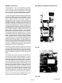
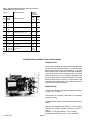
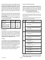
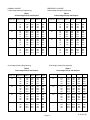
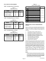
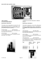
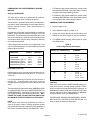
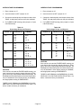
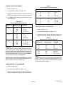
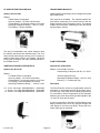
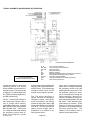
Robonic Automatic
Transfer Switches
Operation and
Maintenance Manual
Instruction leaflet
IL 30-471 (E)
November, 1995
Supersedes issue dated October, 1994
INDEX
Warranty ..................................................................... 2
General Description ................................................... 3
LRO Type Description ................................................ 4
RO Type Description .................................................. 4
SPB Type Description ................................................ 5
Application Information............................................... 5
Microprocessor Based Logic Control Panel ............... 6
Introduction ........................................................... 6
Specification ......................................................... 6
Overall Functional Description ............................. 6
On-Board Programmable Options ........................ 7
Instruction for Dip Switch Settings ........................ 7
Adding Extra On-Board Programmable Options 11
Solid State Logic Control Panel ............................... 12
Logic Control Modules ........................................ 12
Programming Instructions for Plug-in
Control Modules ................................................. 13
Component Identifications for Additional Options .... 17
Typical Schematic and Sequence of Operation ....... 20
Replacing Parts ........................................................ 21
Trouble Shooting Guide ........................................... 22
Recommended Maintenance ................................... 22
CUTLER-HAMMER CANADA
Cutler-Hammer Products
Burlington, Ontario
- Page 1 -
IL 30-471 (E)
WARRANTY
The Company warrants the apparatus to be supplied hereunder to be of the kind designated or specified. The Company shall repair or replace any defective part or parts,
f.o.b. the Company’s factory, repair shop or warehouse,
which prove to be defective under normal and proper use
within one year from the date of shipment, provided that
the Purchaser gives the Company immediate written notice of any such defect or defects. In no event (including,
but not limited to the negligence of the Company, its employees or agents) shall the Company be liable for special
or consequential damages or damages for loss of use and
on expiration of the Warranty period, any liability of the
Company shall terminate. This constitutes the only warranty of the Company and no other warranty or condition,
statutory or otherwise, shall be implied.
IMPORTANT
‘Check equipment for shipping damage immediately
on receipt. In case of damage call the carriers concerned at once for inspection, and request an inspection report. Do not write to us first - notify the carrier
instead. If this precaution is not taken we cannot assist you in recovering the amount of the claim against
the carrier.’
IL 30-471 (E)
- Page 2 -
GENERAL DESCRIPTION
MECHANICAL COMPONENT IDENTIFICATION
CSA Standard C22.2 No. 178-1978 defines an automatic
transfer switch as, “self acting equipment for transferring
one or more load conductor connections from one power
source to another.” The same Standard also gives definitions for type A and type B automatic transfer switches.
“Transfer switch type A means an automatic transfer switch
that does not employ integral overcurrent devices.” “Transfer switch, type B means an automatic transfer switch that
(does) employ integral overcurrent protection.”
Westinghouse Robonic automatic transfer switches are
available in both types. Robonics in type A are equipped
with special instantaneous magnetic only interrupter. The
trip settings of these special interrupters are set (and fixed)
at higher than standard values. They are intended to trip
only if the upstream protective device fails to clear a fault.
Incorporating these special magnetic only interrupters, a
type A Robonic operates in exactly the same way as a
transfer switch not having this feature. In the event that
both devices trip, the Robonic’s control circuitry will automatically initiate transfer to the alternate source. The transfer operation will reset the “tripped” magnetic only interrupter. Information on Interrupting, Closing and Withstand
ratings, for type A Robonics, are given in table 1 on page
5. Type B ‘Robonics’ are equipped with standard thermalmagnetic breakers which will provide the required overload and short circuit protection. Type B Robonics can
also be built using electronic breakers which could include
ground fault tripping as well as overload and short circuit
protection. For application information or assistance with
type B Robonics, refer to Cutler-Hammer.
The Robonic provides automatic transfer of an electrical
load to a standby power supply in the event of drop or loss
of voltage of any or all phases of the normal power supply.
Upon the restoration of the normal supply, the electrical
load is automatically retransferred to the normal power
supply.
Type RO
The transfer motor utilizes the power from the source to
which the electrical load is being transferred. The mechanism provides a positive mechanical interlock to prevent
both breakers being closed at the same time. The mechanism is also designed to leave both breakers trip free in
the closed position, permitting incorporation of thermal and
short-circuit protection in either or both breakers. In the
higher ampacity, type B ‘Robonics’ models, type RO and
SPB type an alarm switch contact is supplied. This contact is connected in the transfer motor circuit to lock the
motor circuit out of operation when the breaker(s) trip on
an overload or short-circuit condition. Then the breaker
has to be manually reset. Instructions for the reset procedure are located on the front of the operating mechanism.
All of the control modules in the Solid State Logic Control
Panel are plug-in units which are easily replaced.
Type LRO
- Page 3 -
IL 30-471 (E)
TYPE “LRO” ROBONIC AUTOMATIC TRANSFER
SWITCH
TYPE “RO” ROBONIC AUTOMATIC TRANSFER
SWITCH
Rated 30 amperes through 100 amperes at 600 volts Ac
maximum 50 or 60 Hertz.
A complete line rated from 150 amperes through 1000
amperes at 600 volts Ac 50 or 60 Hertz.
The mechanism is a lever operated device controlled by a
120 volt unidirectional motor.
The transfer mechanism consists of the transfer motor, a
gear train and two breaker operating cams.
The transfer motor drives a nylon cam which in turn operates a steel lever by sliding a pin along a slot in the back
of the lever. The lever, in turn, operates the two breaker
handles.
In type A ‘LRO Robonics’ there are two micro switches
(NLS, ELS) inside the breakers which are operated by the
breaker’s main contacts to disconnect the transfer motor
power supply and allow the brake to operate. In type B’
LRO Robonics’ the distance travelled is determined by two
projections on the cam. These projections operate two
micro switches (NLS, ELS) which in turn disconnect the
power to the transfer motor causing a brake to operate.
The type LRO has three operating positions. They are
the normal breaker closed and the emergency breaker
open, the emergency breaker closed and the normal
breaker open or both the normal and emergency breakers open but never both normal and emergency breakers
closed.
The type LRO can also be easily manually operated. Open
the lever cover, remove the slide pin and place it in the
hole supplied in the lever cover and close the cover. Then
the lever can be manually operated for whatever position
desired without interference by the automatic control. For
automatic control again, simply align the lever slot with
the hole in the operating cam and replace the slide pin.
The various automatic control components are described
under the section titled “Logic Control”.
SPUR GEAR MESHING RELATIONSHIP
(Bottom View of Top Cover)
The transfer motor drives the center gear which in turn
operates the two secondary gears. There is a projection
in the secondary gears which slides in a groove in the
operating cams moving the cams from side to side. The
breaker handles are set inside two outer guides of the
cam and are also moved from side to side. There are two
micro switches (NLS, ELS) inside the breakers which are
operated by the breaker’s main contacts to disconnect the
transfer motor power supply and allow the brake to operate.
The type “RO” transfer switch has three operating positions, the normal breaker closed and the emergency
breaker open, the emergency breaker closed and the normal breaker open or both the normal and the emergency
breakers open but never both the normal and emergency
breakers closed at the same time.
The type “RO” transfer switch is also easy to operate manually. Simply remove the transfer motor fuse and turn the
operating handle on the front of the transfer mechanism
in a counter clockwise direction until you hear the breakers operated and the indicator is in the desired position.
There will be no interference from the solid state control.
For automatic control again, replace the transfer motor
fuse and the Robonic transfer switch will seek the power
available.
The various control components are described under the
sections titled Logic Control Panels.
IL 30-471 (E)
- Page 4 -
TYPE “SPB” ROBONIC
AUTOMATIC TRANSFER SWITCH
MANUAL OPERATION FROM NORMAL TO
EMERGENCY:
Rated 1200 amperes through 3000 amperes at 600 volts
Ac, 50 or 60 Hertz.
For SPB Automatic Transfer Switches with the four position selector switch, isolate the transfer circuit and engine
starting circuit by placing the “FPSS” in the “OFF” position.
The SPB Automatic Transfer Switch consists of two basic
elements:
1. The power switching panel contains the main power
contacts and transfer mechanism. The main power
contacts connect and disconnect the load to and from
the sources of power. The transfer operation is accomplished by the electrically driven, stored energy
mechanism of the Systems Pow-R Devices.
2. The logic control panel provides the intelligence/supervisory circuits which constantly monitor the condition of the power sources thus providing the intelligence necessary for the operation of the transfer
switch.
The transfer mechanism is energized electrically from the
available source and both breakers read “charged” indicating transfer switch is ready for transfer operation. The
transfer switch is prepared for the next operation after electrical charging which takes only three seconds after transfer. Manual charging is available if for any reason the
transfer switch is not energized. This is done by making
either four full strokes on the charging handle, or several
partial inching strokes. The transfer switch then can be
manually operated.
The switching devices are interlocked to prevent them from
being ep, closed at the same time. This is done by means
of two mechanical interlocks. Each interlock is connected
between the tripping (opening) mechanism of one device
and the latching (closing) mechanism of the other device.
Therefore if one device is closed its interlock will prevent
the other from latching and closing. Both devices cannot
be simultaneously connected to the load by either electrical or manual means.
Auxiliary switches are used in remote control circuits for
interlocks, indicating lights, and signal contacts to indicate
the open or closed position of the breaker main contacts.
For SPB Automatic Transfer Switches without the four
position selector switch, isolate the transfer circuit by disconnecting the two inter-connection plugs. Once that is
done, push the red “Pushto-Open” button on the Normal
Breaker (NB) to open the breaker, then push the green
“Push-to-Close” button on the Emergency Breaker (EB)
to close the breaker.
With normal source power available, the transfer switch
will return to normal when the “FPSS” is returned to the
“AUTO” position or when the two control plugs are re-connected.
The various control components are described under the
section titled “Logic Control”.
Since type A Robonics employ magnetic only breakers,
their interrupting, closing and withstand ratings are the
same value. Under fault conditions, with its “normal”
breaker closed, a Robonic is required to withstand the
energy let through of the normal service protective device
while the fault is being cleared. At the same time, should
the normal voltage fall below the voltage sensing relay’s
selected value, - and if the alternate source were available, the Robonic could transfer before the normal service protective device cleared the fault.
This would require that the Robonic be capable of interrupting the protective device’s let through current. In addition, the Robonic could be required to close in on a fault.
Thus can be seen the need for Robonics to have, interrupting, closing and withstand ratings.
The interrupting, closing and withstand ratings shown in
Table 1 are those for standard typea Robonics. For higher
values, consideration can be given to use of Robonics built
with Tri-Pac or Current Limiting breakers.
The type “SPB” transfer switch has three operating positions, the normal breaker closed and the emergency
breaker open, the emergency breaker closed and the normal breaker open or both the normal and the emergency
breakers open but never both the normal and emergency
breakers closed at the same time.
The type “SPB” Robonic Automatic Transfer Switch is also
easy to operate manually.
- Page 5 -
Table I
Interrupting, Closing and Withstand Rating
- Robonic Type A
Robonic
Continuous
Rating
rms symmetrical amperes
Type
600 Vac 480 Vac
30 to 100 amps
150 to 400 amps
600 lo 1000 amps
1200 to 3000 amps
LRO
RO
RO
SPB
25,000
35,000
25,000
85,000
65,000
65,000
35,000
100,000
120,208,240 Vac
100,000
100,000
65,000
100,000
IL 30-471 (E)
Table 2 - Recommended Upstream Circuit Protective Device for
Type A Robonics, All Classes of Loads
Robonic
Type
Maximum Upstream
Continuous
Rating
(amps)
Breaker Frame Size
Maximum
Upstream
Fuse-Rating*
Class
J or L
Class
K5 or R
LRO
LRO
LRO
30
70
100
HFD, FDC, HJD, JDC, FB-P
100
100
100
100
100
100
RO
RO
150
200
JDC, HKDL, HKD, KDC, HLD, LDC,
LA-P
225
225
225
225
RO
225
250
HKD. KDC, HLD, LDC, LA-P
HKD, KDC, HLD, LDC, LA-P
225
400
225
400
RO
300
HKD, KDC, HLD, LDC, LA-P
400
400
RO
400
HLA, HLC, LD, HLD, NB-P
400
400
RO
600
HMA, HMC, HMD, ND, HND, HNB, NB-P
600
600
RO
RO
800
1000
HNB, ND, HND, HNC, PB, PC, PB-P
PB, PC, PB-P
800
1200
....
....
SPB
SPB
SPB
800, 1200 PB, PC, PB-P, SPB
1600, 2000 PB, PC, SPB
2000, 3000 SPB
2000 (L) ....
3000 (L) ....
4000 (L) ....
*Fuse ratings given are as allowed by CEC. If other ratings are desired, refer to
CEC.
MICROPROCESSOR BASED LOGIC CONTROL PANEL
INTRODUCTION
Cutler Hammer’s Westinghouse brand of Automatic Transfer Switch Single Board Controller is a microcontroller
based transfer switch logic control package. The hardware and software of the controller contains the intelligence
/ supervisory circuits which constantly monitor the condition of the power sources. It provides the intelligence necessary for the operation of the transfer switch. The single
board controller may be used as a replacement for the
solid state logic control panel in the existing older version
of the Robonic Transfer Switches.
SPECIFICATION
The ATS controller has an operating temperature range of
-20 deg. C to +75 deg. C.
The controller circuit board is protected by an insulating
conformal coating.
The specification under normal operating condition are as
follows:
IL 30-471 (E)
Tolerance for Voltage Sensing function: +/-2% of setting.
Tolerance for Frequency Sensing function: +/-0.2 Hz of
setting.
Accuracy of Time Delay Range: +/-2% of setting.
Dial settings for Delay Time are +/-5% of indication.
- Page 6 -
OVERALL FUNCTIONAL DESCRIPTION
the appropriate dip switches.
There are four main groups of functions included in the
ATS single board controller.
•
•
•
•
1. Voltage Sensing Functions
Choices of voltage sensing functions are selectable for
Normal and Emergency sources as follows by means of
factory programming.
•
•
1 phase or 3 phase sensing
Either or both the undervoltage and
overvoltage sensing.
0.1 sec. to 60 sec.
0.16 min. to 10 min.
1 min. to 60 min.
3 min. to 200 min.
4. On Board Indicators
Ten ‘LED” type indicators are installed on the controller’s
circuit board for the following functions.
Norm Volt
Norm. Freq
Dip switches are used to select the pickup and dropout
points for Normal UV, Normal OV, Emergency UV and
Emergency OV functions.
For undervoltage sensing function:
• Available pickup settings: 100%, 95%, 90%
and 85% of normal;
• Available dropout settings: 5%, 10%, 15%,
and 20% from pickup setting.
For overvoltage sensing function:
• Available pickup settings: 105%, 110%, 115%
and 120% of normal;
• Available dropout settings: 5%,10%, 15% and
20% from pick-up setting.
Emer. Volt
Emerg. Freq
TDNE RUN
TDEN RUN
2. Frequency Sensing Functions
TDEC RUN
The controller can be programmed to include either or both
the Underfrequency and Overfrequency sensing for the
Normal and Emergency Sources.
NR ON
ER ON
-- LED on indicates the voltage level of the
Normal Source is within preset limits.
-- LED on indicates the frequency of the Normal Source is within preset limits.
-- LED flashes indicate the frequency of the
Norma( Source is out of preset limits.
-- LED off indicates the Normal frequency
sensing option is not installed.
-- LED on indicates the voltage level of the
Emergency Source is within preset limits.
-- LED on indicates the frequency of the
Emergency Source is within preset limits.
-- LED flashes indicate the frequency of the
Emergency Source is out of preset limits.
-- LED off indicates the Emergency frequency sensing option is not installed.
-- LED flashes indicate TDNE time delay
function is in progress.
-- LED flashes indicate TDEN time delay
function is in progress.
-- LED flashes indicate TDEC time delay
function is in progress.
-- LED on indicates the output relay NR is
energized.
-- LED on indicates the output relay ER is
energized.
-- LED on indicates the output relay ECR is
energized.
Dip switches are used to select the normal frequency of
the power sources and the pickup points.
ECR ON
The normal frequency settings are 50 Hz or 60 Hz. The
dropout points are fixed at 2 Hz differential.
ON-BOARD PROGRAMMABLE OPTIONS
Available pickup settings for the under frequency function
are:
• at 60 Hz nominal = 56, 57, 58, 59 Hz
• at 50 Hz nominal = 46, 47, 48, 49 Hz.
Available pickup settings for the over frequency function
are:
• at 60 Hz nominal = 61, 62, 63, 64 Hz
• at 50 Hz nominal = 51, 52, 53, 54 Hz.
3. Time Delay Functions
ATS Single Board controller can be pre-programmed in the
factory with the following ATS control functions on board:
1)
2)
3)
4)
5)
6)
7)
8)
9)
10)
11)
12)
The controller can be programmed to include three different time delay functions - TDNE, TDEN and TDEC. Each
timing function has four different timing ranges as shown
below. It can be set to any one of the ranges by moving
- Page 7 -
Undervoltage sensing on Normal Source
Overvoltage sensing on Normal Source
Underfrequency sensing on Normal Source
Overfrequency sensing on Normal Source.
Undervoltage sensing on Emergency Source
Overvottage sensing on Emergency Source
Underfrequency sensing on Emergency Source
Overfrequency sensing on Emergency Source
Time Delay Normal to Emergency
Time Delay Emergency to Normal
Time Delay Engine Cool Down
Preferred Source Selection
IL 30-471 (E)
If a Robonic transfer switch has been installed in the field,
any of these options/functions can be added on site by
using the factory programmed “Option Key”. Once the
choice options are activated by the installed “option key”;
the parameter of each function can be setup by positioning the DIP switches labelled SW1, SW2 and SW3 on the
controller circuit board. This allows easy field modification of the control parameter settings at the user’s discretion.
Both the pickup, dropout values of the sensing functions
and the timing ranges of the time delay functions may be
easily changed by following the instructions provided in
the later sections.
Controllers shipped from the factory are programmed to
the user’s original specification or to the standard pickup
and dropout values as follows:
FUNCTION
Undervoltage
Overvoltage
Underfrequency (6OHz)
Overfrequency (6OHz)
Underfrequency (50Hz)
Overfrequency (5OHz)
PICKUP
DROPOUT
90%
105%
58 Hz
62 Hz
48 Hz
52 Hz
80%
115%
56 Hz
64 Hz
46 Hz
54 Hz
Instruction for DIP Switch Setting
The DIP switches located and accessed from the bottomleft portion of the control board must be property set according to application requirements. The three DIP
switches are labelled from left to right as SW1, SW2 and
SW3. All switches are turned ON or OFF by sliding the
switch. As you face the DIP switches, slide:
• > To the TOP to turn the switch ON
• > To the BOTTOM to turn the switch OFF
Always look for the ON and OFF designations on the hardware or printed circuit board to be sure you are setting the
switches correctly.
The following table shows the selection groupings that can
be provided by the three DIP switches.
DIP
Switch
Side
Switch
1
2
3
4
SW1
6
7
8
9
Operating Note:
If the controller is to be used as a replacement for the
solid state logic control package in an existing Robonic
transfer switch, please check the style number labelled
on the transformer module. For the Robonic 11 with a
control transformer module style No. marked as
16OD997GO1--G24, please replace it with transformer
module with style No.3932D65GO1--G26.
SW2
CAUTION:
If the controller is to be used for THREE PHASE sensing,
you must insure that the sensing signals (Normal or Emergency) are fed by a three phase transformer package. On
the Westinghouse brand three phase units sold by Cutler
Hammer, the standard is three phase sensing on NORMAL, and single phase sensing on EMERGENCY.
Description
Pickup and Dropout values selection for the
Normal Source UNDERVOLTAGE SENSING.
Refer to Table I
5Pickup and Dropout values selection for the
Normal Source OVERVOLTAGE SENSING.
Refer to Table 2
Line frequency selection ON=60 Hz OFFHz
1
2
3
4
Pickup and Dropout values selection for the
Emerg, Source UNDERVOLTAGE SENSING.
Refer to Table 3
5
6
7
8
9
Pickup and Dropout values selection for the
Emerg, Source OVERVOLTAGE SENSING.
Refer to Table 4.
1
Underfrequency or/and Overfrequency sensing.
2
Refer to Table 5 and 6.
Pickup and Dropout values selection for the
Emerg. source
3
Underfrequency or/and Overfrequency sensing.
Pickup and Dropout values selection for the
Normal source
Refer to table 7 and 8.
SW3
THREE PHASE SENSING ON EMERGENCY IS AVAILABLE ONLY ASA FACTORY INSTALLED OPTION. If in
doubt, please contact the factory for assistance.
IL 30-471 (E)
4
5
Delay Timing Ranges selection for TDNE function.
Refer to Table 9
6
7
Delay Timing selection for TDEN function.
Refer to Table 10.
8
9
Delay Timing Ranges selection for TDEC function.
Refer to Table 11.
NOTE: Table 12 serves as a quick reference for finding
the actual voltage level that relates to the percentage of
the normal system voltage.
- Page 8 -
NORMAL SOURCE
Undervoltage Sensing Programming
EMERGENCY SOURCE
Undervoltage Sensing Programming
Table 1
Undervoltage Pickup and Dropout
Pickup (%)
Dropout (%)
SW1-1 SW1-2
100
95
90
85
80
ON
ON
ON
0N
ON
ON
ON
0N
ON
OFF
ON
0FF
95
90
85
80
75
OFF
OFF
OFF
OFF
ON
ON
ON
ON
90
85
80
75
70
ON
ON
ON
ON
85
80
75
70
65
OFF
OFF
OFF
OFF
Table 3
Undervoltage Pickup and Dropout
SW1-3 SW1-4
Pickup (%)
Dropout (%)
SW2-1 SW2-2
SW2-3 SW2-4
ON
ON
OFF
0FF
100
95
90
85
80
ON
ON
ON
0N
ON
ON
ON
0N
ON
OFF
ON
0FF
ON
ON
OFF
0FF
ON
ON
OFF
OFF
ON
ON
OFF
OFF
95
90
85
80
75
OFF
OFF
OFF
OFF
ON
ON
ON
ON
ON
ON
OFF
OFF
ON
ON
OFF
OFF
OFF
OFF
OFF
OFF
ON
OFF
ON
OFF
ON
ON
OFF
OFF
90
85
80
75
70
ON
ON
ON
ON
OFF
OFF
OFF
OFF
ON
OFF
ON
OFF
ON
ON
OFF
OFF
OFF
OFF
OFF
OFF
ON
OFF
ON
OFF
ON
ON
OFF
OFF
85
80
75
70
65
OFF
OFF
OFF
OFF
OFF
OFF
OFF
OFF
ON
OFF
ON
OFF
ON
ON
OFF
OFF
Overvoltage Sensing Programming
Overvoltage Sensing Programming
Table 4
Overvoltage Pickup and Dropout
Table 2
Overvoltage Pickup and Dropout
Pickup (%)
Dropout (%)
ON
ON
OFF
0FF
105
110
115
120
125
ON
ON
ON
0N
ON
ON
ON
0N
ON
OFF
ON
0FF
ON
ON
OFF
0FF
ON
OFF
OFF
ON
ON
ON
OFF
OFF
110
115
120
125
130
OFF
OFF
OFF
OFF
ON
ON
ON
ON
ON
OFF
OFF
ON
ON
ON
OFF
OFF
OFF
OFF
OFF
OFF
ON
OFF
ON
OFF
ON
ON
OFF
OFF
115
120
125
130
135
ON
ON
ON
ON
OFF
OFF
OFF
OFF
ON
OFF
ON
OFF
ON
ON
OFF
OFF
OFF
OFF
OFF
OFF
ON
OFF
ON
OFF
ON
ON
OFF
OFF
120
125
130
135
140
OFF
OFF
OFF
OFF
OFF
OFF
OFF
OFF
ON
OFF
ON
OFF
ON
ON
OFF
OFF
Pickup (%)
Dropout (%)
SW1-5 SW1-6
SW1-7 SW1-8
105
110
115
120
125
ON
ON
ON
0N
ON
ON
ON
0N
ON
OFF
ON
0FF
110
115
120
125
130
OFF
OFF
OFF
OFF
ON
ON
ON
ON
115
120
125
130
135
ON
ON
ON
ON
120
125
130
135
140
OFF
OFF
OFF
OFF
- Page 9 -
SW2-5 SW2-6
SW2-7 SW2-8
IL 30-471 (E)
NORMAL SOURCE
Underfrequency Sensing Programming
EMERGENCY SOURCE
Underfrequency Sensing Programming
Table 5
Underfrequency Pickup and Dropout
Table 7
Underfrequency Pickup and Dropout
Pickup (Hz)
Dropout (Hz)
SW2-9
SW3-1
Pickup (Hz)
Dropout (Hz)
SW3-2
SW3-3
59
58
57
56
57
56
55
54
ON
OFF
ON
OFF
ON
ON
OFF
OFF
59
58
57
56
57
56
55
54
ON
OFF
ON
OFF
ON
ON
OFF
OFF
49
48
47
46
47
46
45
44
ON
OFF
ON
OFF
ON
ON
OFF
OFF
49
48
47
46
47
46
45
44
ON
OFF
ON
OFF
ON
ON
OFF
OFF
Overfrequency Sensing Programming
Overfrequency Sensing Programming
Table 6
Overfrequency Pickup and Dropout
Table 8
Overfrequency Pickup and Dropout
Pickup (Hz)
Dropout (Hz)
SW2-9
SW3-1
Pickup (Hz)
Dropout (Hz)
SW3-2
SW3-3
61
62
63
64
63
64
65
66
ON
OFF
ON
OFF
ON
ON
OFF
OFF
61
62
63
64
63
64
65
66
ON
OFF
ON
OFF
ON
ON
OFF
OFF
51
52
53
54
53
54
55
56
ON
OFF
ON
OFF
ON
ON
OFF
OFF
51
52
53
54
53
54
55
56
ON
OFF
ON
OFF
ON
ON
OFF
OFF
NOTE:
Underfrequency sensing and/or Overfrequency sensing functions
may be programmed into the ATS Controller through the “Option
Program Key”. In the case which both “Uf” and Of” Sensing
functions are activated, the same DIP switch settings will be
applied to both functions. Two equivalent sizes of sensing
hysteresises will be assigned to below and above the system
line frequency respectively.
IL 30-471 (E)
NOTE:
Underfrequency sensing and/or Overfrequency sensing functions
may be programmed into the ATS Controller through the “Option
Program Key”. In the case which both “Uf” and Of” Sensing
functions are activated, the same DIP switch settings will be
applied to both functions. Two equivalent sizes of sensing
hysteresises will be assigned to below and above the system
line frequency respectively.
- Page 10 -
DELAY FUNCTION PROGRAMMING
Table 12
Normal System Voltage
TDNE - Time Delay Normal To Emergency
120 208 220 240 380 400 415 480 600
Table 9
TDNE Range Select
RANGE
0.1 sec. to 60 sec.
0.16 min. to 10 min.
1.0 min. to 60 min.
3.0 min. to 200 min.
SW3-4
SW3-5
ON
OFF
ON
OFF
ON
ON
OFF
OFF
TDEN - Time Delay Emergency To Normal
Table 10
TDEN Range Select
RANGE
SW3-6
0.1 sec. to 60 sec.
0.16 min. to 10 min.
1.0 min. to 60 min.
3.0 min. to 200 min.
ON
OFF
ON
OFF
65%
78
135 143 156 247 260 270 312 390
70%
84
146 154 168 266 280 291 336 420
75%
90
156 165 180 285 300 311 360 450
80%
96
166 176 192 304 320 332 384 480 Std. UV Dropout
85%
102 177 187 204 323 340 353 408 510
90%
108 187 198 216 342 360 374 432 540 Std. UV Pickup
95%
114 198 209 228 361 380 394 456 570
100%
120 208 220 240 380 400 415 480 600
105%
126 218 231 252 399 420 435 504 630 Std. OV Pickup
110%
132 229 242 264 418 440 457 528 660
115%
138 239 253 276 437 460 477 552 690 Std. OV Dropout
120%
144 249 264 288 456 480 498 576 720
125%
150 260 275 300 475 500 519 600 750
130%
156 270 286 312 494 520 540 624 780
135%
162 281 297 324 513 540 560 648 810
SW3-7
ON
ON
OFF
OFF
TDEC - Time Delay Engine Cool Down
Table 11
TDEC Range Select
RANGE
SW3-8
SW3-9
0. 1 sec. to 60 sec.
0.16 min. to 10 min.
1.0 min. to 60 min.
3.0 min. to 200 min.
ON
OFF
ON
OFF
ON
ON
OFF
OFF
ADDING EXTRA ON-BOARD PROGRAMMABLE
OPTIONS:
When it is desired, extra on-board programmable control
options can be added to a Robonic with the single board
controller. The list of the installable on-board options are
as follows;
1.
2.
3.
4.
5.
6.
7.
8.
9.
Overvoltage sensing on Normal Source.
Underfrequency sensing on Normal Source.
Overfrequency sensing on Normal Source.
Overvoltage sensing on Emergency Source.
Overfrequency sensing on Emergency Source.
Time Delay Normal to Emergency.
Time Delay Emergency to Normal.
Time Delay Engine Cool Down.
Preferred Source Selection.
After the factory programmed “Option Key” which contains
the choice option(s) and the associated parts, if required,
are received, turn off the Normal Source and make sure
to disable the Emergency Source by turning the Gen set
start control to manual. Plug the ‘Option Key” into the 1 0pin socket (J2) that is located in the centre of the controller circuit board. The Key is not polarized and can be
plugged in either way. Install any extra parts if supplied.
Turn the Normal Source back on. The new option
function(s ) will be programmed into the single board controller.
NOTE:
The DIP switches located and accessed from the bottom-left portion of the control board must be properly
set according to application requirements for the added
control option(s). Please refer to the section that contains the instruction for DIP Switch Setting.
- Page 11 -
IL 30-471 (E)
SOLID STATE LOGIC CONTROL PANEL
LOGIC CONTROL
VOLTAGE SENSING MODULE
COMBINATION VOLTAGE/ FREQUENCY SENSING
MODULE
Style Number 782OC97GO1
Style Number 782OC99GO1
The module can be programmed to use with 1Ø or 3Ø
systems and perform either the undervoltage or the
overvoltage sensing function. It is applicable to both emergency and normal source monitoring.
The module is designed for use with 1Ø or 3Ø systems
and can be programmed for either undervoltage or
overvoltage and either Underfrequency or Overfrequency.
It is applicable to both emergency and normal source monitoring.
1Ø Undervoltage
3Ø Undervoltage
For undervoltage sensing, this card is normally set at an
80% dropout and a 90% pickup.
1Ø Overvoltage
3Ø Overvoltage
For overvoltage sensing, this card is normally set at a 105%
pickup and a 115% dropout.
1Ø Undervoltage
3Ø Undervoltage
For undervoltage sensing, this card is normally set at an
80% dropout and a 90% pickup.
1Ø Overvoltage
3Ø Overvoltage
For overvoltage sensing, this card is normally set at a 105%
pickup and a 115% dropout.
1Ø Underfrequency
1Ø Overfrequency
For underfrequency or overfrequency sensing, the card is
factory calibrated at 50 or 60 Hz. The standard values of
pickup and dropout are as follows:
IL 30-471 (E)
Type
System
Pickup
Frequency Hz
Hz
Dropout
Hz
Underfrequency
Underfrequency
Overfrequency
Overfrequency
60
50
60
50
56
46
64
54
- Page 12 -
58
48
62
52
TIME DELAY MODULE
BLANK
Style Number 782OC96GO1
Style Number 1266C77GO1
Module can be programmed for any one of five timing
ranges:
1 - 60 sec. timer
4 -240 sec. timer
0.13- 8 min. timer
0.5 - 32 min. timer
1 - 64 min. timer
Use to cover any unused card slots.
All can be used to accomplish TDEC, TDEN and TDNE
functions.
All Cards Mechanically Interlocked
All cards are interlocked mechanically to prevent insertion into the wrong function slot. All cards have a repeat
accuracy over a 20 to + 60°C temperature change of +
3%. Dial settings are + 10% of indication.
After making adjustments, tighten mounting screws
(screws are not captive).
RELAY DRIVER
Style Number 1266C77GO2
This card is used in place of any of the timing modules
when instantaneous operation is required.
- Page 13 -
IL 30-471 (E)
Programming and adjustments for plug-in sensing
control modules.
Cards shipped from the factory are programmed to the
user’s original specification, or to the standard pickup and
dropout values as follows:
TIME DELAY MODULE
FUNCTION
PICKUP
DROPOUT
Undervoltage
Overvoltage
90%
105%
80%
115%
Style Number 782OC96GO1
The Timer Card is a multi-range timer. The card may be
used as a replacement for older single range timer cards
in existing equipment.
Programming the card
The card may be “programmed” for any one of five timing
ranges by simply moving a jumper to the appropriate position. The actual time desired is then set with a front
accessible potentiometer.
Programming the Timer Card
1. If the Timer Card must be removed from a Transfer
Switch that is in service, it is a good idea to disable
the logic first by separating the logic disconnect plug,
so that a possibly undesired transfer is avoided.
CAUTION: Disconnecting the logic WILL cause the
Engine Generator to start unless it has been disabled.
2. The card is supplied with a single jumper, which must
be placed on the Range Select Terminals as follow:
RANGE SELECT TIMING RANGE *
1
4
8
32
64
Reprogramming of the card may be accomplished by using the attached instructions with Table 13 and 14 or Table
13A and 14A.
It is recommended that you remove ALL jumpers from Jl
through J7. As supplied from the factory there are erictigh
jur-npers to program the card for any function and value.
The card may be programmed for either UNDERVOLTAGE
or OVERVOLTAGE. Attempting to program the card for
both voltage sensing functions at the same time WILL
CAUSE THE CARD TO MALFUNCTION AND POSSIBLY DAMAGE THE ELECTRONICS ON THE CARD!!
NOTE:
If the card is to be used as a replacement for older versions of the plug-in cards in existing equipment, please
check the Date Code that is stamped on the nameplate of
the Control Transformer Module (16OD997GO1-G24).
1 - 60 Seconds
4 - 240 Seconds (.07 - 4 Min.)
8 - 480 Seconds (.13 - 8 Min.)
.5 - 32 Minutes
1 - 64 Minutes
*NOTE: Timing ranges shown are guaranteed. Actual
available range may be slightly larger.
VOLTAGE SENSING MODULE
Style Number 782OC97GO1
The card may be used as a replacement for older versions of the plug-in cards in existing equipment.
The card may be “programmed” to perform a voltage sensing function, either undervoltage or overvoltage.
Programming of the card is accomplished by positioning
jumpers on the positions labelled J1 through J7 on the
board itself. This allows easy filed modification of the card
at the user’s discretion. Both the function and the pickup
and dropout values may be easily changed by following
the instructions provided.
IL 30-471 (E)
- Page 14 -
*
For Robonics with control transformer module’s date code dated AFTER Sept. 1/92,
follow Table 13 and 14 to program the voltage
sensing function.
*
For Robonics with control transformer module’s date code dated BEFORE Sept. 1/92,
follow Table 13A and 14A to programme the
sensing function.
COMBINATION VOLTAGE/FREQUENCY SENSING
MODULE
*
For Robonics with control transformer module’s date
code dated AFTER Sept. 1/92, follow Table 13 and 14
to program the voltage sensing function.
*
For Robonics with control transformer module’s date
code dated BEFORE Sept. 1/92, follow Table 13A and
14A to program the voltage sensing function.
Style No. 782OC99GO1
The card may be used as a replacement for older versions of the plug-in cards in existing equipment.
The card may be “programmed” to perform a voltage sensing function, either undervoltage or overvoltage; and a frequency sensing function, either underfrequency or
overfrequency.
UNDERVOLTAGE PROGRAMMING
1. Place a jumper on J6.
2. Insure that there is NOT a jumper on J7.
Programming of the card is accomplished by positioning
jumpers on the positions labeled Jl through J12 on the
board itself. This allows easy field modification of the card
at the user’s discretion. Both the function and the pickup
and dropout values may be easily changed by following
the instructions provided.
3. Choose the desired pickup and dropout values from
TABLE 13 and place jumpers on the pins indicated.
4. For THREE PHASE sensing, place jumper on Jl (see
CAUTION below).
Cards shipped from the factory are programmed to the
user’s original specification, or to the standard pickup and
dropout values as follow:
Table 13
Undervoltage Pickup and Dropout
PICKUP (%) DROPOUT(%)
FUNCTION
Undervoltage
Overvoltage
Underfrequency (60 Hz)
Overfrequency (60 Hz)
Underfrequency (50 Hz)
Overfrequency (50 Hz)
PICKUP
DROPOUT
90%
105%
58 Hz
62 Hz
48 Hz
52 Hz
80%
115%
56 Hz
64 Hz
46 Hz
54 Hz
95
90
85
80
75
J2
J2, J4
J2, J5
J2, J4, J5
90
85
80
75
70
J3
J3, J4
J3, J5
J3, J4, J5
85
80
75
70
65
J2, J3
J2, J3, J4
J2, J3, J5
J2, J3, J4, J5
Programming the card
Reprogramming of the card may be accomplished by using the attached instructions with table 13, 14, 13A, 14A,
15 and 16.
It is recommended that you remove ALL jumpers from Jl
through J12. As supplied from the factory, there are
enough jumpers to program the card for any function and
value.
The card may be programmed for either UNDERVOLTAGE
or OVERVOLTAGE, and either UNDERFREQUENCY or
OVERFREQUENCY. Attempting to program the card for
two voltage sensing or two frequency functions ... WILL
CAUSE THE CARD TO MALFUNCTION AND POSSIBLY DAMAGE THE ELECTRONICS ON THE CARD!!
NOTE:
If the card is to be used as a replacement for older versions of the plug-in cards in existing equipment, please
check the Date Code that is stamped on the nameplate of
the Control Transformer Module (16OD997GO1 - G24).
JUMPERS
CAUTION:
If the card is to be used the THREE PHASE sensing, you
must insure that the sensing signals (Normal or Emergency) are fed by a three phase transformer package. On
Westinghouse brand three phase unit sold by Cutler-Hammer, the standard is three phase sensing on NORMAL,
and single phase sensing on EMERGENCY.
THREE PHASE SENSING ON EMERGENCY IS AVAILABLE ONLY AS A FACTORY INSTALLED OPTION. If in
doubt, contact the factory for assistance.
- Page 15 -
IL 30-471 (E)
OVERVOLTAGE PROGRAMMING
UNDERVOLTAGE PROGRAMMING
1. Place a jumper on J7.
1. Place a jumper on J6.
2. Insure that there is NOT a jumper on J6.
2. Insure that there is NOT a jumper on J7.
3. Choose the desired pickup and dropout values from
TABLE 14 and place jumpers on the pins indicated.
3. Choose the desired pickup and dropout values from
TABLE 13A and place jumpers on the pins indicated.
4. For THREE PHASE sensing, place jumper on Jl (see
CAUTION below).
4. For THREE PHASE sensing, place jumper on Jl (see
CAUTION below).
Table 14
Overvoltage Pickup and Dropout
Table 13A
Undervoltage Pickup and Dropout
PICKUP (%)
DROPOUT(%)
JUMPERS
PICKUP (%)
105
110
115
120
125
none
J4
J5
J4, J5
95
90
85
80
75
none
J4
J5
J4, J5
110
115
120
125
130
J2
J2, J4
J2, J5
J2, J4, J5
90
85
80
75
70
J2
J2, J4
J2, J5
J2, J4, J5
115
120
125
130
135
J3
J3, J4
J3, J5
J3, J4, J5
85
80
75
70
65
J3
J3, J4
J3, J5
J3, J4, J5
120
125
130
135
140
J2, J3
J2, J3, J4
J2, J3, J5
J2, J3, J4, J5
CAUTION:
If the card is to be used the THREE PHASE sensing, you
must insure that the sensing signals (Normal or Emergency) are fed by a three phase transformer package. On
Westinghouse brand three phase unit sold by Cutler-Hammer, the standard is three phase sensing on NORMAL,
and single phase sensing on EMERGENCY.
JUMPERS
CAUTION:
If the card is to be used the THREE PHASE sensing, you
must insure that the sensing signals (Normal or Emergency) are fed by a three phase transformer package. On
Westinghouse brand three phase unit sold by Cutler-Hammer, the standard is three phase sensing on NORMAL,
and single phase sensing on EMERGENCY.
THREE PHASE SENSING ON EMERGENCY IS AVAILABLE ONLY AS A FACTORY INSTALLED OPTION. If in
doubt, contact the factory for assistance.
THREE PHASE SENSING ON EMERGENCY IS AVAILABLE ONLY AS A FACTORY INSTALLED OPTION. If in
doubt, contact the factory for assistance.
IL 30-471 (E)
DROPOUT(%)
- Page 16 -
OVERVOLTAGE PROGRAMMING
Table 15
Overvoltage Pickup and Dropout
1. Place a jumper on J7.
PICKUP (Hz)
DROPOUT(Hz)
JUMPERS
46
47
48
49
44
45
46
47
none
J11
J12
J11, J12
56
57
58
59
54
55
56
57
J10
J10, J11
J10, J12
J10, J11, J12
2. Insure that there is NOT a jumper on J6.
3. Choose the desired pickup and dropout values from
TABLE 14A and place jumpers on the pins indicated.
4. For THREE PHASE sensing, place jumper on Jl (see
CAUTION below).
Table 14A
Overvoltage Pickup and Dropout
PICKUP (%)
DROPOUT(%)
JUMPERS
OVERFREQUENCY PROGRAMMING
105
110
115
110
115
120
125
J2
J2, J4
J2, J5
J2, J4, J5
115
120
125
130
J3
J3, J4
J3, J5
J3, J4, J5
120
125
130
135
J2, J3
J2, J3, J4
J2, J3, J5
J2, J3, J4, J5
1. Place a jumper on J9.
2. Insure that there is NOT a jumper on J8.
3. Choose the desired pickup and dropout values from
TABLE 16 and place jumpers on the pins indicated.
Table 16
Overfrequency Pickup and Dropout
PICKUP (Hz)
51
52
53
54
61
62
63
64
CAUTION:
If the card is to be used the THREE PHASE sensing, you
must insure that the sensing signals (Normal or Emergency) are fed by a three phase transformer package. On
Westinghouse brand three phase unit sold by Cutler-Hammer, the standard is three phase sensing on NORMAL,
and single phase sensing on EMERGENCY.
THREE PHASE SENSING ON EMERGENCY IS AVAILABLE ONLY AS A FACTORY INSTALLED OPTION. If in
doubt, contact the factory for assistance.
DROPOUT(Hz)
53
54
55
56
63
64
65
66
JUMPERS
none
J11
J12
J11, J12
J10
J10, J11
J10, J12
J10, J11, J12
NOTE:
Please refer to Table 12 (Normal System Voltage) in the
previous section. It serves as a quick reference for finding the actual voltage level that related to the percentage
of the normal system voltage.
UNDERFREQUENCY PROGRAMMING
1. Place a jumper on J8.
2. Insure that there is NOT a jumper on J9.
3. Choose the desired pickup and dropout values from
TABLE 15 and place jumpers on the pins indicated.
- Page 17 -
IL 30-471 (E)
DT AND DTM TIME DELAY RELAYS
TRANSFORMER MODULES
Option # 32A and 32B
Modules include all necessary control, voltage sensing and
logic transformers.
Ratings 2 Watts Power Consumption
Input coil Voltage - 120 volts at 50/60 Hertz
Contact Rating - 10 amperes resistive at 120 volts
Operating Temperature Rating - - 30°C to + 65°C
Time Ratings - Various available
Two versions are available. The standard module has
three phase monitoring of the normal source and one
phase monitoring of the emergency source. The optional
module has three phase monitoring on both the normal
and emergency sources.
The relay is incorporated in the control scheme to stop
the transfer switch with both breakers open, This is to
allow residual load voltage to decay prior to closing on
another supply which could be out of phase. When the
timing cycle is complete, the relay reinitiates transfer to
the available source.
PLANT EXERCISER
TIME DELAY ENGINE STARTING RELAY
Option # 23A, 23B and 23C
Option # 2A, 2B and 2C
Ratings - Input voltage 120 volts
Contact rating 16 Amps at 250 VAc, 45 - 60 Hz.
Ratings 0.75 Watts Power Consumption
Input coil voltage - 120 volts at 50/60 Hertz
Contact Rating - 10 amperes resistive at 120 volts
Time Range - Various available (see below)
Operating Temperature Range - - 30°C to + 65°C
0.5 - 15 sec. time range S# 5086AOlGOl Option #2A
4 - 120 sec. time range S# 5086AOlGO2 Option #2B
10 - 300 sec. time range S# 5086AOlGO3 Option #2C
150 hour battery back-up
Operating Temperature Range: - 10°C to + 55°C
Accuracy: +/- 4 minutes per year
Description
The Plant Exerciser utilizes a programmable electronic
time switch. It incorporates a seven day time base, therefore each day of the week can be uniquely programmed.
For convenience, Block Programming is also provided,
whereby up to seven days can be grouped together if the
“on” and “off” times are the same.
In case of power failure, the built-in nickel-cadmium timer
battery maintains the time of day, program storage and
LCD display for 150 hours (six days). During this time,
output relays are de-energized.
IL 30-471 (E)
- Page 18 -
APPLICATION
PORTABLE TEST KIT
The Plant Exerciser is a Program Time Switch which
functions to start and stop the engine-generator set and
transfer switch automatically at pre-selected intervals
or times. This electronic timer can be programmed to
operate the switch at specific times of the day daily or
specific days of the week. The cycle repeats weekly.
The Plant Exerciser may be used in two different ways
as an accessory for transfer switches.
An inexpensive, portable test kit, # 1278C67GO1, is available for convenient field testing and calibration of all plugin cards and output relays. The only power source required is a 120V convenience outlet. A selector switch
allows the operator to test individual cards or to simulate
ATS operation by having the source monitoring cards
drive the time delay cards which in turn drive the output
relays, exactly as in actual use. Calibration checks or
changes can thus be accomplished without the necessity of energizing the alternate power source.
1. It may be used to simulate an interruption in the
normal source of supply at selected intervals, at
least once per week, causing the transfer switch
components to function, including start-up of the
engine-generator set and transfer of load to the
generator supply. At the end of the interval it will
initiate the transfer back to normal supply and shut
down the engine-generator.
or
2. It may be used to start up an engine-generator set
at selected intervals, at least once per week, but
without causing the transfer switch to operate and
transfer the load to the generator supply. At the
end of the interval it will cause the engine-generator
to shut-down.
INSTRUCTIONS: TO OPERATE THE ENGINE FOR
AN INTERVAL ONCE EACH WEEK, WITH OR WITHOUT OPERATION OF THE TRANSFER SWITCH ...
1. Follow the programming instructions that come with
the time switch, set up the actual time of day and
the day of the week.
2. Determine the time of day and the day of the week
for this test. Program the “ON” command by pressing “CHI” once, and the display will show “CHI ON”
and indicate “- - : - -” for the time.
3. Press the “DAY” key to select the desired day of
the week.
4. Insert the hour and minutes at which time the “ON”
command is to take place, then press the “CHI” key
to enter the program.
5. The display will indicate “CHI OFF” and “- - : - -”.
Program the “OFF” command by using the steps
outlined above
6. Press the “
” key to return to actual time of day
display. After the time switch is programmed, it will
automatically “look back” and assume the correct
“ON” or “OFF” switch position.
NOTE:
Regarding changing, checking or canceling programs and manual over-ride switch operations,
please refer to the instructions that are provided
with the Electronic Time Switch.
- Page 19 -
IL 30-471 (E)
TYPICAL SCHEMATIC AND SEQUENCE OF OPERATION
SWITCH DE-ENERGIZED
NORMAL INTERRUPTER CLOSED
Consider the Robonic in the normal
operating position, with normal
power available and the normal interrupter closed. The following are
energized: U.V. (undervoltage module), TDES (time delay engine start),
and NR (normal relay).
The U.V., monitoring all 3 phases of
the normal power, senses a dip or
loss of voltage which instantly
causes NR to deenergize. Contacts
NR2 and NR4 open, and contacts
NRl and NR3 close. TDES times
out, closing its contact and initiating
the emergency system start up.
When the emergency system
IL 30-471 (E)
EL, NL
NAS, EAS
ELS, NLS
TM
BS
TDES
NR5
ET3, ET4
TDEC
TSS
PILOT LIGHTS (OPTIONAL)
LOCKOUT SWITCHES (OPTIONAL)
LIMIT SWITCHES
TRANSFER MOTOR
BRAKE SOLENOID
TIME DELAY ENGINE START COIL/CONTACT (OPTIONAL)
INSTANTANEOUS ENGINE START CONTACT
OPTIONAL TRANSFORMERS
TIME DELAY ENGINE COOL DOWN (OPTIONAL)
TEST SELECTOR SWITCH
reaches correct levels of voltage and
frequency, ER is energized and contact ER2 closes. This completes the
emergency control circuit, and TM
(transfer motor) begins to operate.
First, The normal interrupter is
opened, and then the emergency
interrupter is closed. At this point,
the ELS (emergency limit switch)
contacts change state, and the BS
(motor brake) closes, preventing TM
over travel. The NLS (normal limit
switch) contacts change state in
preparation for re-transfer to the
normal power source.
- Page 20 -
Upon return of stabilized normal
power, NR is re-energized disabling
the emergency control circuit, and
enabling normal control circuit. The
TM operates, opening the emergency interrupter and closing the
normal interrupter. When the retransfer is completed, the NLS contacts change state isolating TM, and
BS closes. TDES becomes energized opening its contacts. TDEC
times out to allow the emergency
generator to run unloaded and cool
off before shutting down. The
Robonic is now ready to react to
another normal power failure.
REPLACING PARTS
The Robonic Automatic Transfer Switch has been designed
to have all components accessible and readily removable
from the front of the panels. The Robonic Transfer Switch
is divided into two basic sections. The upper section consists of the main contacts and transfer mechanism, the
lower section consists of all the automatic control devices.
CAUTION
When replacing any parts of the mechanism, control transformers or breakers, isolate the Robonic Transfer Switch
from any possible source of power.
To remove the transfer mechanism of the LRO transfer
switch, first open the cover and remove the slide pin from
the operating cam, then remove the centre bolt, the mechanism will lift straight off. The breakers and transfer motor
bracket are held by four screws for ease of removal and
replacement. When replacing the mechanism, first set it
on the Robonic with the breaker handles in the holes provided and then fasten the centre bolt reasonably tight with
the mechanism fully movable with an equivalent swing
distance up and down.
To remove the transfer mechanism of the RO transfer
switch, remove the four bolts holding it, taking note of which
holes the bolts were in, then lift the mechanism straight
off. The breakers are held by two bolts at one end and the
bus connectors on the other end. The transfer motor is
mounted to the transfer mechanism cover and centre drive
gear. When replacing any part of the transfer mechanism,
be sure that the scribe lines of the gears are in a straight
row (example shown on page 5)
To prevent operation of the transfer switch while replacing
the mechanism or components, disconnect all sources of
power.
When replacing the mechanism move it about until the
breaker toggles fit between the mechanism fingers and
then fasten the bolts tightly. To test for proper operation,
first operate manually and then connect 120 volt, 60 Hertz
supply to motor leads and observe operation for free movement and proper breaker operation.
All Robonic transfer switch breakers and mechanisms have
allowed some adjustments for mounting to assure proper
operation without slipping or binding. Be sure all hardware is tightened sufficiently before re-energizing any
transfer switch.
To replace any of the octal plug-in relays, pull old units
straight out and insert the replacement unit. Due to the
tight fit of the receptacle and pins, you may have to move
the relay about a little to pull it out. DO NOT INTERCHANGE ANY RELAY WITH ANY OTHERS!
Parts List
Part Name
Parts Common to Robonic
Single Board Controller
Controller main board c/w standard protection
Output relay, used for NR, ER and ECR
LEXAN Cover
Style No.
lB27390HOI
3A84214HOl
3A84223HOl
Solid State Logic Control Panel
Plug-in Modules
Timer adjustable, for TDEN, TDEC, TDNE
with ranges of
1-60 sec., 4-240 sec., 0.13-8 min.
0.5-32 min., 1-64 min.
Relay driver - used in place of timers, for
instantaneous operation
1Ø Frequency sensing module, “UF” or “OF”
for “Normal” or “Emergency”
Frequency/Voltage sensing module
Voltage sensing module, “lØ” or “3Ø”,”UV”
or “OV” for “Normal” or “Emergency”
Blank cover, for unused module space
Instantaneous relay, used for NR, ER, and EC
Options
7820C96G01
1266C77GO2
7820C99G01
7820C99G01
7820C97G01
1266C77G01
7070A59H0I
Time delay relay for engine starting, adjustable
0.5-15 sec.
5086A0lG0l
Time delay relay for engine starting, adjustable
4-120 sec.
5086A01G02
Time delay relay for engine starting, adjustable
10-300 sec.
5086A0lG03
DT/DTM Time Delay relay
5086A03H03
Plant Exerciser
lA00815H01
Battery Charger 12V
Battery Charger 24V
1259C26G01
1259C26G03
4 Position s/s fixed
4 Position s/s keyed
7070A56H01
7070A56H02
Transformer Modules
600V, for LRO, RO
480V, for LRO, RO
416V, for LRO, RO
400V, for LRO, RO
380V, for LRO, RO
240V, for LRO, RO
208V, for LRO, RO
For Type LRO Robonic
Standard
3932D65G25
3932D65G04
3932D65G03
3932D65G22
3932D65G21
3932D65G02
3932D65G01
Mechanism - FD
Mechanism - CA
Motor Assembly c/w Limit Switch
Motor Assembly no Limit Switch
Motor
Operating Cam
Slide Pin
Limit Switch
Optional
3932D65G26
3932D65GI4
3932D65Gl3
3932D65G24
3932D65G23
3932D65Gl2
3932D65Gll
833C224G01
833C224G02
833C223G01
833C223G02
lA00684H0l
688A548G01
688A731H0l
688A747H0l
For Type RO Robonic
Mechanism 150 to 300A
Mechanism 150 to 400A
Mechanism 600 to 1000A
Motor
Solenoid
Brake Shoe Assembly
Operating Cam - MA/NB
To replace any solid state logic modules, pullstraight out
Operating Cam - KA/LA
Auxiliary & Limit Switch
and insert the replacement unit.
- Page 21 -
833C226G51
833C226G01
833C226G02
688A749H03
688A740H01
688A739GO1
623B814H0l
572B774H0l
688A747H0l
IL 30-471 (E)
TROUBLE SHOOTING
D. Robonic Retransfers the Load, but Gen-Set Continues to Run.
The Robonic is energized; proceed with care!
A. Gen-Set Does Not Start When Test Switch is
Operated and Held in “Test” Position.
1. Check Operation. Make sure the Test Selector
Switch is held in “test” position longer than the TDES
time delay.
2. Check Engine Controls. Make sure control is in “Automatic” position. Make sure batteries are charged
and connected. Make sure engine start circuit is
wired.
1. Check Operation. Make sure time has passed to
allow for TDEC time delay.
2. Check Engine Controls. Make sure engine starting
control is in the “Automatic” position.
3. Check Signal Circuit. Disconnect and tape start signal wires which are connected to the control panel
terminals 51 and 52. Connect ohmmeter between
these terminals; reading should indicate an open
circuit.
RECOMMENDED MAINTENANCE
3. Check Wiring. Make sure the start signal wires from
the engine controls are connected to the correct terminals on the Control Panel. See the Schematic/
Wiring Diagram.
1. DO NOT perform dielectric tests on the equipment
with the control components in the circuit.
2. DO NOT use loctite.
4. Check Signal Circuit. Disconnect and tape start signal wires. Connect the ohmmeter between the control panel terminals 51 and 52. The reading should
indicate an open circuit. Turn the Test Selector
Switch to “Test” position. After TDES time delay, the
ohmmeter should indicate a closed circuit.
3. Check lubricant in high speed bearings of the motor
and the low speed bearings of the gear box. For
lubrication use Dow Corning Silicon DC44 or equivalent on the high speed bearings and Aero Shell No.
6 grease or equivalent in gear box after 5000 operations.
B. Robonic Does Not Retransfer the Load After
Normal Source is Returned or After Test Switch
is returned to “Auto’ position.
4. Check if control components are tight in sockets.
1. Check Operation. Make sure time has passed to
allow for TDEN time delay.
5. Periodically inspect all terminals (load, line and control) for tightness. Re-tighten all bolts, nuts and accessible hardware. Clean or replace any contact
surfaces which are dirty, corroded or pitted.
2. Check Normal Source Voltage Levels. On a three
phase system voltmeter should read phase to phase
voltage.
3. Check Signal Circuit. Confirm that the Test Switch
has reclosed to measuring 0 volts between terminals T60 and T61.
C. With Gen-Set Running, Robonic Does Not Transfer the Load to Emergency.
1. Check Operation. Make sure time has passed to
allow for TDNE time delay.
2. Check Engine Controls. Check generator output frequency and voltage. Output should be at least 90%
of nominal voltage and 95% of nominal frequency.
Make sure generator output circuit breaker is closed.
3. Check Wiring. Voltmeter should read phase to phase
voltage between Transfer Switch EA and EB.
IL 30-471 (E)
- Page 22 -
6. Robonics should be in clean, dry and moderately
warm locations. If signs of moisture are present,
dry and clean transfer switch. If there is corrosion
try to clean it off. If cleaning is unsuitable, replace
the corroded parts. Should dust and/or debris gather
on the transfer switch, brush, vacuum or wipe clean.
DO NOT blow dirt into breaker or terminals.
7. Test the transfer switch operation. While the Robonic
is exercising, check for freedom of movement, hidden dirt or corrosion and any excessive wear on the
mechanical operating parts. Clean, lubricate or replace parts where necessary.
8. Check all adjustable control components (time delay and voltage sensing relays) for correct settings.
9. If the type “RO” mechanism is removed be sure that
the scribe lines on the gears are in line. When reassembling the drive mechanisms, be sure that they
are fastened to the correct holes in the frame and
that the breaker handles are between the cam fingers. (One breaker has to be on and the other off.)
10. Voltage and/or frequency cards may be removed from
a ROBONIC (for servicing, etc.) without disruption of
power supply to the connected load. Output relays
NR and ER, in combination with their timers or drivers, will continue to provide partial protection. Dropout voltage is 50%; pickup voltage is 70%.
Note:
When servicing logic control, or transformer module,
disable the motor circuit.
TYPE LRO ROBONICS
CAUTION
Do not overtighten the pivot screw inside the operating arm. This screw was correctly adjusted at the factory to provide low friction movement of the operating
arm without excessive play.
Do not overtighten the set screw holding the operating cam on the motor shaft.
- Page 23 -
IL 30-471 (E)