1
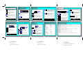
FOLD
FOLD
Connecting the 34401A to a PC using Agilent Connection Expert
Agilent Connection Expert (ACE) is an Agilent IO Libraries utility that configures the IO interface between the 34401A
and your PC. The IO Libraries are contained on the Agilent Automation-Ready CD or may be downloaded from the
Agilent Developer Network website at: http://adn.tm.agilent.com.
1. Install the Agilent IO Libraries on your PC and connect a GPIB cable between the PC and the 34401A.
2. From the PC taskbar, click the Agilent IO Control icon
and select ‘Agilent Connection Expert’ from the menu.
3. Select the PC’s GPIB interface and select ‘Add Instrument’
from the Connection Expert menu bar.
Safety Summary
Do not defeat power cord safety ground feature. Plug
in to a grounded (earthed) outlet. Do not use product in
any manner not specified by the manufacturer.
CAT II (300 v) IEC Measurement Category II. Inputs can be
connected to mains (up to 300 VAC) under
Category II overvoltage conditions.
Do not install substitute parts or perform any
unauthorized modification to the product. Return the
product to Agilent Technologies or a designated repair
center for service to ensure that safety features are
maintained.
WARNING
WARNING
A WARNING notice denotes a hazard. It calls attention
to an operating procedure, practice, or the like that, if
not correctly performed or adhered to, could result in
personal injury or death. Do not proceed beyond a
WARNING notice until the indicated conditions are fully
understood and met.
CAUTION
4. Select the GPIB0 interface and then select the
34401A GPIB address (factory setting = 22).
A CAUTION notice denotes a hazard. It calls attention
to an operating procedure, practice, or the like that, if
not correctly performed or adhered to, could result in
damage to the product or loss of important data. Do
not proceed beyond a CAUTION notice until the
indicated conditions are fully understood and met.
Symbols
Earth Ground
5. To verify the IO connection, open ‘Interactive IO’
and send the *IDN? command to the 34401A by
selecting “Send & Read”.
Chassis Ground
6. Use the ‘Options’ tab to increase the timeout period
for commands with execution times > 5 ms (e.g. *TST?).
Risk of electric shock
Refer to manual for additional safety
information.
Agilent 34401A
6½ Digit Multimeter
Quick Start Tutorial
Product Reference CD-ROM. All product documentation, software, and examples
are included on the Agilent 34401A Product Reference CD-ROM.
Main Power and Test Input Disconnect: Unplug
product from wall outlet, remove power cord, and
remove all probes from all terminals before servicing.
Only qualified, service-trained personnel should
remove the cover from the instrument.
Line and Current Protection Fuses: For continued
protection against fire, replace the line fuse and the
current-protection fuse only with fuses of the specified
type and rating.
Front/Rear Switch: Do not change the position of the
Front/Rear switch on the front panel while signals are
present on either the front or rear set of terminals.
Switching while high voltages or currents are present
may cause instrument damage and lead to the risk of
electric shock.
IEC Measurement Category II. The HI and LO input
terminals may be connected to mains under IEC
Measurement Category II overvoltage conditions for
measurement of line voltages up to 300 VAC. To avoid
the danger of electric shock, do not connect the inputs
to mains for line voltages above 300 VAC. Connect to
mains only at an outlet, or in a device connected to
such an outlet, on a branch circuit protected by a circuit
breaker. See "Safety Notices" in the User's Guide for
further information.
Protection Limits: To avoid instrument damage and
the risk of electric shock, do not exceed any of the
protection limits indicated on the terminal panel and
defined in the User's Guide.
1. Preparing for Use
Adjust the Carry Handle.
Connect the Power Cord.
Grasp the handle by the
sides and pull outward:
Then plug in the instrument.
Line voltage switch is set at factory for
country of destination – verify setting
before applying power.
Connect the Test Leads to the Input Terminals.
AC or DC
Voltage*
-
-
ADDITIONAL SAFETY INFORMATION
+
For further information, refer to the "Safety Notices"
section in the Agilent 34401A User's Guide.
See "Safety Summary" on the back of this tutorial.
Edition 1
NOTE TO PRINTER:
NOTE TO PRINTER:
(See folding diagram at right)
4-wire
Resistance or
Temperature
AC or
DC
Current
Copyright © 2007 Agilent Technologies, Inc.
Printed In Malaysia
August 2007
E0807
This is FACE “E” (short face, folds inside)
I
+
* Also used for capacitance,
continuity, diode test, frequency, 2-wire resistance,
and 2-wire temperature
measurements.
34401-90005
Then adjust the handle
to the desired position:
NOTE TO PRINTER:
This is “FACE A” (the FRONT)
This is FACE “F” (the BACK)
See folding diagram below:
(See folding diagram at right)
Turn
Page for
Step 2
FOLD
2. Power, Input Terminal Selection,
and Local Control
3. Setting the Function
5. Math Operations
The measurement function is set using the
following keys:
- turns the 34401A on and off. A selftest occurs during the power-on
sequence.
- selects the front or rear panel
terminals as the input to the
34401A.
- when preceded by the “Shift” key the
functions shown above the keys are
selected.
- transfers instrument control from the
computer (remote) to the front panel
(local).
Example: Period function selected
200.001
Rear
uSEC
Resolution is the number of digits the 34401A
can measure or display. Resolution is also
unique to the function selected and is set using
the following keys:
- dBm measurement relative to a
resistance referenced to 1 mW
(Math menu: dBm REF R).
reading = measurement – null value
2
reading = 10Log10(measurement / reference resistance/ 1mW)
Example: dBm measurement @ ~ 3 VDC - 600Ω reference
resistance
05.02287 MAX
Measurements are triggered from the front panel
using the following keys:
- disables auto-triggering (default) and
issues a single trigger to the 34401A
each time the key is pressed.
- selects 4 digit resolution
- manually decreases the range
- manually increases the range
- selects 5 digit resolution
Example: display indicating 10 volt range, 4 digit resolution
VDC
- value subtracted from the measurement
(Math menu: NULL VALUE)
6. Triggering
- selects between auto-range and manual
range
MAN
- dB measurement relative to value
in ‘dB Relative’ register (register
value is first db measurement
after dB function is enabled).
11.7842
MaTh
4. Setting the Range and Resolution
03.987
Selected math operations are available from the
34401A front panel using the keys:
Example: maximum value indicated with Math operation
‘Min/Max’ enabled
04.09495 VDC
The measurement range is unique to the
selected function. The range is set using the
following keys:
Menu Navigation
- displays minimum and maximum values
for the triggered set of readings.
Example: display indicating remote operation and rear panel
terminals selected.
Adrs Rmt
FOLD
- selects 6 digit resolution
For increased measurement speed, select 4
digits. For increased accuracy, select 6 digits.
- Auto: enables auto-triggering if
the 34401A is in single trigger
mode (above).
- Hold: displays the measurement
after three consecutive readings
within the sensitivity band
(Trigger menu: READ HOLD).
DBm
MaTh
The front panel menu provides access to a
subset of the 34401A functionality. The menu is
navigated using the following keys:
- selects (saves) parameter and exits
the menu (Enter is not a shifted function).
- enables menu (if off) and recalls
the last command displayed
when the menu was exited.
Sequence:
- enables the front panel menu
Note: for numeric parameters (0-9):
- scrolls through menus ‘A’ - ‘G’
- selects menu command list and
scrolls through commands
- selects and increments/
decrements each digit
individually
Example: number of reading samples increased to 5
- selects parameter list and scrolls
through parameters
0000
34401A Power-on and Reset States
Front Panel Menu Reference
Measurement Configuration
Function
AC Filter
Range
Resolution
Integration Time
Autozero
Input Resistance
Continuity Threshold
A: MEAS MENU
1: AC FILTER > 2: CONTINUITY > 3: INPUT R > 4: RATIO FUNC > 5: RESOLUTION
Math Operations
State
Function
dBm Reference Resistance
Registers
DCV
20 Hz
Autorange
5 digits, slow mode
10 PLCs
On
10 MΩ
10Ω
Off
Null
600Ω
Cleared
Auto-trigger
Automatic
1
0.10% of range
Other
Reading Memory
Cleared
NOTE TO PRINTER:
This is FACE “B”
This is FACE “C”
(See folding diagram on page 1)
(See folding diagram on page 1)
B: MATH MENU
1: MIN-MAX > 2: NULL VALUE > 3: dB REL > 4: dBm REF R > 5: LIMIT TEST > 6: HIGH LIMIT > 7: LOW LIMIT > 8: SCALE >
9: SCALE GAIN > 10: SCALE OFST
C: TRIG MENU
1: READ HOLD > 2: TRIG DELAY > 3: N SAMPLES
D: SYS MENU
1: RDGS STORE > 2: SAVED RDGS > 3: ERROR > 4: TEST > 5: DISPLAY > 6: BEEP > 7: COMMA > 8: REVISION >
9: STORE STATE > 10: RCL STATE > 11: POWER ON
E: I/O MENU
1: GPIB ADDR > 2: INTERFACE > 3: BAUD RATE > 4: PARITY > 5: LANGUAGE
F: CAL MENU
1: SECURED > [1: UNSECURED > 2: CALIBRATE] > 3: CAL COUNT > 4: MESSAGE
Triggering
Trigger Source
Trigger Delay
Samples Per Trigger
Reading Hold Sensitivity
NOTE TO PRINTER:
SMPLS
G: TEMP MENU
1: TEMP FUNC > 2: UNITS > 3: RTD TYPE 4: RTD Ro > 5: T/C TYPE > 6: THERM TYPE > 7: JUNCT TEMP
NOTE TO PRINTER:
This is FACE “D” (short face, folds inside)
(See folding diagram on page 1)