1
Installation Instructions for the
SK-210ME (Key Unit)
SK-210KME (Keypad Unit)
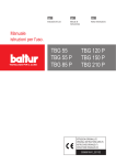
ME Sr. III Alarm System
Operation Guide
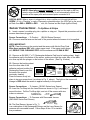
The ME Senior III Alarm Module is designed
to handle up to 12 terminals, (6 or 12 port
strips and 6 port splitter boxes in any combination), protecting up to 144 items. New microprocessor technology enables the system to
identify the number of alarm sensors connected
to it, monitor battery level, and perform a continuous series of system-wide tests that look for
changes resulting from possible tampering.
Lighted LED Bar Graphs visually depict the
condition of batteries and AC power. When an
alarm occurs, it shows precisely which sensor
on which terminal caused the alarm.
The ME Alarm System utilizes the Se-Kure
Controls complete line of “LE” sensors.
SK-210KME
ME Sr. Keypad Alarm Module
SKP-416K
Special Allen Key
SK-295
AC/DC Power Supply
Terminals:
SK-206ME
6 Port ME Strip Module
SK-212ME
12 Port ME Strip Module
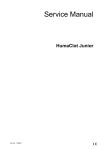
Install the AC/DC Adapter:
SK-107ME
6 Port ME Splitter
SK-295
AC/DC Power Supply
Fig. 1
1. Plug the SK-295 AC/DC Adapter* into the
power supply jack on the back side of the alarm
module as shown in Fig. 1 at right.
Note: Always use a Se-Kure Controls (SK-295)
AC/DC Power Supply with Se-Kure alarms.
(Using a universal adapter could damage the
system and would void the warranty).
2. Plug the other end of the adapter into any
standard 110v wall outlet.
*International Users May Require a Special Adapter for 220v, (not supplied).
Terminal Connection
(from ME Strip Alarm or ME Splitter Box)
Reading Time: 8 Minutes
Page 1
Fig. 2
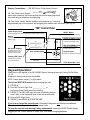
Battery Installation:
3. Insert and turn the key, then remove the Phillips Head
Screw on the side of the alarm module to open the battery
compartment as shown in the Fig. 2 at right.
4. Insert (6) “C” cell (alkaline) batteries into the battery
tubes with the (+ -) polarity as indicated.
5. Replace the battery cover plate and the screw.
Note: If the security screw is loose, or removed, when
armed, the alarm will (((sound))).
IMPORTANT! Make sure the AC/DC Power Supply is
plugged in before installing batteries.
Install Terminals:
When the power is first applied to the (SK-210KME) Keypad Alarm System, the keypad
uses the factory pre-set code: 1-2-3-4.
6. To deactivate Keypad Alarm Systems: Enter the factory pre-set code: [*] 1-2-3-4.
To deactivate Keyed Alarm Systems: Insert the key and turn counterclockwise.
(NOTE: The unit will BEEP every 30 seconds to indicate the unit is disarmed).
7. Plug the 1st (Splitter or Strip) into the back of the alarm module as shown in Fig. 2 above.
Alarm Module
6 Port
Strip
Alarm
6 Port
Strip
6 Port
Splitter
6 Port
Splitter
Box
12 12
PortPort
Strip
Alarm
Strip
Fig. 3
■ ■ ■
●
■
■ ■ ■
AC/DC
Power Supply
Computers
Phones
Lap Tops
Calculators
Portable CD
Players
Power
Tools
Boom Boxes
The ME Senior III is designed to work with up to 12 terminals, (Splitters or Strips) each with a
capacity of up to 12 sensors to protect a maximum of 144 products. You can use any combination of
ME Splitters or Strips, (up to a maximum of 12), daisy-chained together, as shown in Fig. 3 above.
8. After the 1st Splitter or Strip is plugged into an ME Alarm Module, additional
Splitters or Strips can be daisy-chained together. Remove (and save) the
(SK-209ME) Terminal End Plug that is plugged in at the end of each terminal,
SK-209ME
and plug the next ME Splitter or Strip in there.
ME Terminal End Plug
(NOTE: The ME End Plug MUST BE placed in the last outlet of the last terminal).
Installing “LE” Sensors:
The ME Alarm System utilizes the Se-Kure Controls complete line of “LE” Sensors.
Sensors are available to adhere, lasso, and tie-wrap to display products. If you require additional
assistance finding the right sensor(s) to accommodate your specific needs, your knowledgeable
Customer Service Representative is available to help you.
Cable
(Available in Straight or Coil)
Phone Connector
(Plugs into an ME Splitter or Strip)
Page 2
SK-904PC/LE
6’ (Coiled) Rectangular Sensor
Sensor
(Adheres to Display Product)
NOTE: Shunt plugs are not required and must not be used on ME terminals, when the ME system is activated, it will automatically detect and
monitor all the open ports and sensored ports connected to it.
SPECIAL NOTE: When a sensor is plugged into a strip or splitter port, the port light will turn
GREEN. (If it is a “Dangling” or open or improperly connected sensor, the LED Light on the sensor
will flash from RED to GREEN to RED . . . also, the Terminal and Bar Graph lights will flash).
Sensor Connections: – To Splitters & Strips
9. Insert a sensor’s modular plug into a splitter or strip port. Repeat this procedure until all
sensors have been plugged in.
Sensor Connections: – To Product
(SK-904 Series Sensors)
10. Choose a small flat area on the back of the product where the sensor is to be applied.
VERY IMPORTANT!
NOTE: Clean the area on the product and the sensor with Alcohol Prep Pads.
Wipe these surfaces DRY with a clean paper towel. If the paper towel shows
dirt, REPEAT THIS CLEANING STEP until the surfaces are CLEAN & DRY!
Clean &
Wipe Dry
11. Remove an SK-905 (1" x 2") Rectangular Adhesive Pad from its backing sheet. Apply
the adhesive pad to the bottom of the sensor, making sure that the center hole of the adhesive lines up with the plunger on the bottom of the sensor. (See Fig. 4 below).
12. Remove the backing sheet
Fig. 4
from the other side of the
SK-905
adhesive pad and position the
Rectangular Sensor over the
Remove
flat area of the product
Adhesive
Rectangular
Fig. 5
Backing
Adhesive Pad
previously cleaned.
Press the sensor firmly into
place to insure a proper bond, (as shown in Fig. 5 above). The light on the sensor will
change to RED when the sensor is applied correctly to the product
Sensor Connections: – To Lenses (SK-943 Series Lens Sensor)
13. Insert the Tie-Wrap into the Lens Sensor as shown in Fig. 6, and wrap it
around the lens. Pull the Tie-Wrap tight, and cut off the excess with wire
cutters or scissors.
SK-943
SK-943T Tie-Wrap
Tie Sensor
Fig. 6
Sensor Connections: – To Cameras with Removable Lenses
(SKD-0443 Series Dual Sensor)
SKD-0443
Dual Sensor
Fig. 7
14. The Dual Sensor, (shown in Fig. 7)
is a combination of the Rectangular Sensor and the Lens Sensor for
cameras with removable lenses. Follow Steps 9 thru 13 for installation procedures.
Page 3
Sensor Connections: – (SK-953 Series Collar Lasso Sensor)
Fig. 8
SK-953
Collar Lasso Sensor
15. The Collar Lasso Sensor
has a wire connector that loops around the product and plugs back
into itself using a telephone modular plug.
16. The Collar “Lasso” can be installed onto products by “Lassoing”
any enclosed part of the product and plugging this module back into itself, (see Fig. 8).
“ME” Control Panel
Power Supply Light
RESET Button
(Indicates that the unit is receiving an external Power Supply 110v/AC)
(Reactivates Corrected Sensor)
Battery
(Light Motion Stops at Current
Battery Level)
Bar Graph Displays
(Example shows a “HIT” or
Tampered Sensor on the
3rd Port of Terminal #6)
GREEN (STANDBY) Light
{
1
2
3
4
TERMINAL
5 6 7 8
AC POWER
9
10 11 12
BATTERY
HIGH
1
2
3
4
SENSOR
5 6 7 8
9
RED (PROGRAM) Light
10 11 12
LOW
(Flashes to Indicates a
Disarmed or Stand-By Mode)
RESET
MED
(Indicates the System Will
Accept a New Code #)
TEST
STANDBY
PROGRAM
ME Sr. III ALARM CENTER
Chasing LED Lights
(Indicate that the System
is in an Armed Mode)
Model No.
SK-210KME
Keypad Lights
Keypad Control
Se-Kure Controls,® Inc.
1-(800) 322-2435
www.se-kure.com
TEST Button/Horn Test
(Resets the System)
Keypad Operation:
When power is first applied to the SK-210KME System, the keypad uses the Factory Pre-Set Code:
1-2-3-4.
Replace the factory code as soon as possible.
NOTE: Codes cannot contain [*] or [#] symbols.
The System MUST BE Disarmed before changing the code.
1. PRESS [#]
2. Enter the Current 4-Digit Code: ___-___-___-___ or
the Factory Preset Code (when first installing).
3. PRESS [*] (The RED LED Light will come on indicating that you
have 8 secs. or the keypad will reset to the last entered code).
4. Enter a NEW 4-Digit Code: ___-___-___-___
5. PRESS [*] then PRESS [#] to store the code.
If you lose or forget the current code: Disconnect the power and remove the batteries.
This will reset the keypad to the factory preset code.
To keep the current code durring battery replacement: Leave the AC/DC Power Supply
plugged into the Control Module to retain your code when changing batteries.
Page 4
Arm the System:
With all the Terminals, (Strips & Splitters), and
Sensors attached:
• Check to see there are no flashing
LED Lights on Sensors.
• Check to see there are no Lights lit on
the Bar Graphs.
If no lights are lit, proceed to step 17.
If lights are still lit, proceed to steps 19 & 20.
17. Arm the system by entering your 4-digit
code, or the factory preset code of: [*]1-2-3-4.
(Keyed Units: Turn the key clockwise & remove).
Disarm the System:
18. Disarm the system by entering your 4-digit
code, or the factory preset code of: [*]1-2-3-4.
(Keyed Units: Turn the key counterclockwise). If
a sensor was detached, the horn will stop beeping; the Bar Graphs will light showing the 1st
location of a tampered sensor, and the battery
light will stop moving at the point the system was
disarmed.
When an Alarm Occurs:
If any part of the system is disturbed, the ME
Alarm System will give both visual & audible
alerts. The horn will )))SOUND(((, the LED Light
on affected sensor(s) will FLASH. . . red, green,
red. . . and the LED light on the Terminal , (Strip
or Splitter) will FLASH green. In addition, the
Bar Graphs on the ME Control Panel will light-up
showing the 1st location of one or more
detached sensors.
19. Determine the location of the 1st Sensor
Alarm by checking the Bar Graphs. You will
see which terminal and sensor in the chain is
affected. We strongly recommend that you reactivate the sensor by removing it from the product,
and reapplying it, (see steps 9 through 13).
Press and hold the RESET Button until the next
affected sensor is indicated on the Bar Graph.
The light on the 1st detached sensor will turn
from GREEN to RED.
20. The Bar Graph shows the next affected
sensor; follow the same procedure to reactivate
the sensor connected to each product. Press
the RESET Button after each reactivated connection to clear that alarm.
When you press the RESET Button to clear
each alarm, the horn will )))SOUND(((, and the
sensor’s LED LIght will turn from GREEN to
RED.
Rearm the System:
21. When all Sensor Bar/Lights and Terminal
lights are OUT, you may rearm the system. Arm
the system by entering your 4-digit code, or the
factory preset code of: [*] 1 - 2 - 3- 4.
(Keyed Units: Turn the key clockwise & remove).
Special Reset:
If someone forgot to disarm the system before
removing a Strip, Splitter or Sensor, the alarm
)))SOUNDS((( and the Bar Graph will indicate
the location of the event.
22. Disarm the system, reconnect the break, or
rework the display. (Remember that an ME
Terminal End Plug MUST BE placed in the last
outlet of the last terminal, and no where else in
the system). Press and hold the TEST Button
until the horn sounds. This reconfigures the system. You can now rearm the system without
reactivating any sensors. We recommend that
you review the cause of the alarm conditions
before using the Special Reset.
Low Battery Warning:
When the battery falls below recommended levels, the Battery Bar Graph lights stop, and the
horn will “Double Beep” 7 to 10 seconds.
23. Unlock and remove the screw on the side of
the alarm module to open the battery compartment with a Phillips Head screw driver as shown
in Fig. 1 on page 2.
24. Replace the (6) “C” cell (alkaline) batteries
loading them into the battery tubes with the (+ -)
polarity as indicated.
25. Replace the battery cover.
Page 5
Installation Instructions for the
ME Jr. plus 2 Alarm System
SK-800KME Series
ME Jr. Terminals
SK-80108ME
ME Jr. plus 2 (8) Port Strip
SK-807ME
ME Jr. plus 2 (8) Port Splitter Box
Connects
Alarm Module
to Splitters &
Strips &
Splitters to
Splitters
SK-800KME
ME Jr. plus 2 Alarm Module
SK-3690
(Optional) “Where it’s At Light”
SK-809
Telephone Modular
“End Plug”
SK-847-x
Extension
Fig. 1
Battery Installation:
1. Remove the screw that restricts the battery
door from opening using a phillips head
screwdriver as shown in Fig. 1.
2. Insert the key and turn it to the disarmed
position (the key cannot be removed in the
disarmed position).
Note: The battery door will not open without the
key in the lock and in the disarmed position.
3. Remove the battery door.
4. Before installing batteries, plug the (SK-195)
AC/DC Power Supply into the Alarm Module
jack marked Pwr. Input as shown in Fig. 2.
5. Install (4) fresh “C” Cell Alkaline batteries
following (+) and (-) polarity shown in Fig. 3.
Fig. 2
Fig. 3
VERY IMPORTANT! When installing batteries,
always follow the polarity indicated on the
battery holder.
6. Close the door as shown in Fig. 4. The horn
will “Double Chirp” until the door is securely
closed.
7. Replace the battery door retaining screw as
shown in Fig. 5. (If the key is in the disarmed
position for 1-1/2 minutes, the horn will
“Single Chirp” every 15 seconds to indicate
that the unit is in the disarmed mode.
Fig. 4
Fig. 5
Circuit “A” Light &
Circuit “B” Light
AC Power Light
Will be lit if a Termination
“End Plug” is not installed.
Will )))flash((( if an alarm has
been caused on that circuit.
Will not be lit when all
sensors and the Termination
“End Plug” have been
properly installed.
Low Battery Light
Will be lit when the SK-195 AC/DC
Power Supply is supplying power to
the Alarm Center.
Will )))flash((( when batteries
should be replaced.
Will )))flash((( if no batteries are
installed and the AC power is on.
Key Disarm Light
Keypad Program Light
Will be lit when the Alarm Center is
Disarmed using the Key-Lock.
Will be lit when the Alarm
Center is in the keypad
programming mode and
ready to accept a new code.
Keypad Disarm Light
Will be lit when the Alarm Center is
Disarmed using the Key-Lock.
)))
SK-HORN
Remote Horn
SK-807ME
8 Large Port KE Splitter Box
SK-80108ME
8 Port KE Strip
SK-800KME
ME Jr. plus 2 Alarm Module
SK-195
AC/DC Power Supply
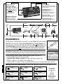
Installation:
The ME Jr. plus 2 Control Module has (2) circuits; one marked Circuit “A” and one marked
Circuit “B”. Any combination of up to (10) Splitters/Strips can be Daisy-Chained to the
Control Module as long as the total number from both circuits Does Not Exceed (10). If all
(10) Splitters/Strips are chained to a single circuit, an “End Plug” must be installed in the
other circuit. An “End Plug” must also be installed in the last splitter of each chain.
SK-809
Telephone Modular “End Plug”
Special Note: Place the ME Jr. plus 2 in the Key Disarm Mode to install splitters and sensors. The Key Disarm Mode prevents the unit from Automatically Arming after (4) minutes.
• After arranging display, connect Splitters/Strips together using the 6 ft.
SK-847-x (x = Cable Length in Feet)
(SK-847) cables (provided with each splitter).
Extension (Connects Alarm Module
to Splitters & Splitters to Splitters)
If specific lenth cables is required: you may order them using Part No.
(SK-847-x), where x = the length of the cable in feet.
• Connect an ME Jr. Sensor to a port on the Splitter/Strip and to the corresponding display product.
Selecting Sensors for Display Product: (Sensors are available in Straight (P/LE) & Coiled (PC/LE).
2.
SK-902
1" x 1" Bug Sensor
SK-943
Tie Sensor
SK-961
Ant Sensor
SK-904
1" x 2" Rectangular
Sensor
SK-953
collar Lasso Sensor
SK-968
Mini Phone Sensor
SK-927
Parallel Port Sensor
SK-955
Slim-Line Sensor
SK-990
Bendable Label
Sensor
Other Straight,
Coiled &
Dual Sensors
Are
Available.
Ask Your
Customer Service
Representative
For Details.
The “Where It’s At” LED Light:
All ME Jr. Splitter Boxes and Strips are
equipped with a “Where It’s At” light jack, for
this optional accessory. When an alarm occurs,
the light will )))flash((( to alert associates of the
location of the alarm. Plug them in wherever
needed, and adhere the
light where it can be seen
from a distance, (usually
at the top of a display).
Keypad Instructions:
Features:
A Keypad System has been added along
with the mechanical key system to provide
dual control.
Entering your access code or turning the key
will arm or disarm the alarm module.
The Yellow “Keypad Program” LED Light
above the keypad indicates when the
device is in the “Program Mode” and able
to accept new access codes from the user.
During an alarm, the horn will )))sound(((; at
this time, you can either (1) enter your
security access code on the keypad, or (2)
turn the key to place the system in the DisArmed Mode.
The Keypad System features a device
called Auto-Arm. It is intended to automatically arm the system after (4) minutes.
Operation of the Keypad System:
When power is first applied to the device, it
will use the factory default code of : 1, 2, 3,
4. The user should change this code as
soon as possible. The system will accept the
default code until a new one has been
entered.
Always enter the [*] key before entering the
access code.
Changing the Default Access Code:
Follow the steps below to change the access
code as desired. The codes cannot contain
the [*] star or the [#] pound symbol keys!
The system must be in the “Dis-Armed”
Mode before changing the code.
1. PRESS [#]
2. ENTER the current (4) digit
Security Code:
[_____] + [_____] + [_____] + [_____]
3. PRESS [*]
(After Step 3, the Yellow LED Keypad
Program Light will be ON).
4. ENTER the new (4) digit Security Code:
[_____] + [_____] + [_____] + [_____]
5. PRESS [*] (One More Time) then
PRESS [#] (To Store the New Code)
Note: The steps to change the Access Code
must be done within (8) eight seconds, or the
keypad will be reset to the last stored security code, and you will be required to repeat
the steps.
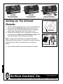
3.
SK-800KME
SK-800ME
SK-800MEI
ME Jr. plus 2 Alarm Module
with Key Switch & Keypad
ME Jr. plus 2 Alarm Module
with Key Switch Only
ME Jr. plus 2 Alarm Module
with Key Switch & Infrared Remote
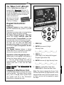
Setting Up The Infrared
Remote:
1. Open the battery compartment door to reveal the dip switches on
the side of the SK-800MEI Alarm Module, as shown in Fig. 6.
2. Unscrew and open the SK-882 Infrared Remote. It is fastened
together with a small phillips head screw, shown in Fig. 7.
3. Arrange the Dip Switches into any configuration to create your
own encoded signal. Make sure the Dip Switches match on the
Alarm Module and the Infrared Remote Transmitter.
Note: It is highly recommended that you change the Dip Switch
settings from the factory default. This protects the system from being
tampered by anyone with an infrared remote set on the factory
default.
Fig. 6
Dip Switches
SK-882 - Infrared
Remote Transmitter
Fig. 7
Dip Switches
Battery
4. Close the Alarm Module and the Infrared Remote Transmitter.
4.
Se-Kure Controls,® Inc.
On the Web: www.se-kure.com
E-Mail: [email protected]
3714 Runge Street • Franklin Park, IL 60131 • 1-(800) 322-2435 • (847) 288-1111 • Fax: (847) 288-9999
Rev. 7/22/02
©2002 Se-Kure Controls,® Inc.
SCI-9759
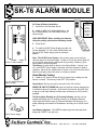
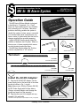
Installation & Operation Instructions for the
SK-T6 ALARM MODULE
SK-T6
When
installing
batteries be
sure to
follow the
POLARITY
marked on
the battery
holder
AC Power & Battery Installation:
1. Unlock the cover and open the lid.
2. Install (6) NEW “AA” Alkaline Batteries in the
SK-T6 Alarm Module, onto the battery holder as
shown at right.
VERY IMPORTANT! When installing the batteries,
follow the polarity indicated on the battery holder.
3. Close the lid.
4. To install the AC/DC Power Supply, plug the unit
into any standard 110-115v outlet, and the other end
into the AC/DC Power Supply Jack on the Alarm
Module.
6 Port T-6 Alarm Module
Note: The AC/DC Power Supply: is the primary power source and provides the power for the sensor lights. If power is cut off, the sensor lights will
go out, but the alarm remains active and will )))sound((( if battery is good.
Check battery condition regularly.
The Battery: provides back-up power to the Alarm Module. If power is cut
off, or the AC/DC Power Supply is removed, the Alarm transfers to battery
operation. Alarm will not sound when AC power is cut off, but remains active
and will )))sound((( without AC power in an alarm condition.
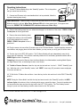
Alarm Module Testing:
5. Install an “LE” sensor into any of the (6) sensor ports, making sure the
sensor is “closed.” Turn the key to the LEFT “ON” position.
(6) “AA” Alkaline Batteries
(Not Included)
SK-110
Extra Key
Special Note: The key can only be removed in the “ON” position.
WHEN THE UNIT IS TURNED ON: each port that has a sensor plugged into
it will flash for about (5) seconds. At the end of (5) seconds, the green light
at the top of the Alarm Module will flash once and remain on if AC power is
available.
The Red Light(s) Flashing for (5) Seconds Indicates: that the unit has
located that sensor and it is “working correctly.” In the Battery Mode the
Green Light that Flashes every (5) Seconds Indicates: that the unit is constantly checking the condition of the batteries, and they are in GOOD condition.
SK-195
Low Battery Indication: The GREEN indicator light will continually flash
along with a “BEEP” from the horn.
AC/DC Power Supply
©2001 Se-Kure Controls,® Inc.
Rev. 5/4/01
®
Se-Kure
Controls,
Inc.
3714 Runge Street • Franklin Pk., IL 60131 • 1-(800) 322-2435 • (847) 288-1111 • Fax (847) 288-9999
SCI-9610
Operating Instructions:
6. Turn the T6 Alarm Module Key to the “Stand-By” position. This is the position
that you cannot remove the key.
7. Connect an LE sensor to the merchandise that is to be protected, follow the
important cleaning step closely.
VERY IMPORTANT! Clean the area on the product and the bottom of the sensor with Alcohol Prep Pads.
While the alcohol is still wet, Wipe These Surfaces DRY with a clean paper towel. If the paper towel
shows dirt, REPEAT THE CLEANING STEP until the surfaces are Clean & Dry!
8. Remove the backing sheet from an adhesive and apply it to the bottom of the sensor. PRESS it FIRMLY into place to form a good bond.
9. Remove the second backing sheet,
and apply the sensor to the merchandise
on the area cleaned for the sensor.
PRESS it FIRMLY into place to form a
good bond.
SK-905
Rectangular
Adhesive Pads
Remove adhesive backing
10. Plug the sensor into one of the (6) sensor ports of the T6 Alarm Module. Continue applying sensors to
merchandise, and plugging them into the Alarm Module, you may use any or all (6) ports to secure items.
11. Turn the key to the LEFT “ON” position. The T6 Alarm Module will now independently scan the (6)
sensor ports for tampering. The unit also continually checks the AC and battery powered condition with a
GREEN light to show it is operating.
Tampering is the removal of Sensors from the Alarm Module, from Merchandise, Inserting Metal Objects
into Open Sensor Ports, or the attempt to short out a Sensor.
12. To Add or Remove Sensors: Insert the key into the lock and turn it to the RIGHT “Stand-By” position. While the unit is in the “Stand-By” mode, it will “BEEP” once every (30) seconds to warn employees
to turn the unit back on.
13. To Re-Set the T6 Alarm after an Alarm: Insert the key into the lock and turn it to the RIGHT “Stand-By”
position.
NOTE: During the “Alarm Mode” and after the key has been turned to the “Stand-By” position, the RED
indicator lights will continue to flash, indicating which sensor caused the alarm. Correct the problem/sensor that caused the alarm and turn the key back to the LEFT “ON” position. The T6 will always search
through its ports and check battery condition when turned to the “ON” position.
See Us on the World Wide Web: www.se-kure.com or E-Mail: [email protected]
©2001 Se-Kure Controls,® Inc.
Rev. 5/4/01
®
Se-Kure
Controls,
Inc.
3714 Runge Street • Franklin Pk., IL 60131 • 1-(800) 322-2435 • (847) 288-1111 • Fax (847) 288-9999
SCI-9610