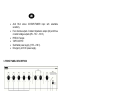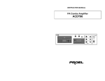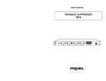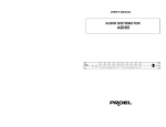
1
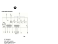
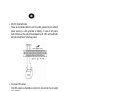
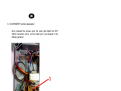
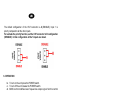
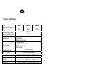
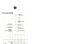
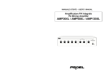
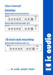
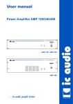
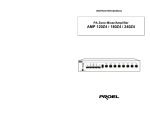
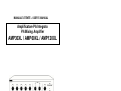
MANUALE UTENTE – USER’S MANUAL
Amplificatore PA Integrato
PA Mixing Amplifier
AMP30XL / AMP60XL / AMP120XL
1. IMPORTANT SAFETY INSTRUCTIONS
CAUTION:
To reduce the risk of electric shock do not remove cover (or back panel). No
user serviceable parts inside. Refer servicing to qualified personnel only.
WARNING:
To reduce the risk of fire or electric shock, do not expose this apparatus to
rain or moisture.
This symbol is intended to alert the user of the presence of uninsulated
dangerous voltage within the product enclosure that may be of sufficient
magnitude to constitute a risk of electric shock to persons.
This symbol is intended to alert the user of the presence of important operating
and maintenance (servicing) instruction in the literature accompanying the
appliance. Please carefully read the owner’s manual.
INSTRUCTIONS:
All safety and operating instructions should be read before the product is operated.
Retain these instructions:
All safety and operating instructions should be retained for future reference.
This owner’s manual should be considered as a part of the product and it must accompany it
every time, and delivered to the new user when this product is sold. In this way the new owner will
be aware of all the installations, operating and safety instructions.
Heed all warnings:
All warnings on the product and in owner’s manual should be adhered to.
Heed all warnings.
Follow all instructions:
All operating and user’s instructions must be followed.
Sentences preceded by
symbol contain important safety instruction. Please read it carefully.
DETAILED SAFETY INSTRUCTIONS.
Water and moisture:
This apparatus should not be used near water (i.e. bathtub, kitchen sink, swimming pools,
etc.)
Ventilation:
This apparatus should be placed in a way that his position doesn’t interfere with correct
ventilation. This unit, for example, should not be placed on a bed, sofa cover o similar
surfaces that could cover ventilation openings, or placed in a built-in installation, such a
bookcase or a cabinet that could block air flow trough ventilation openings.
Heat:
This apparatus should be placed away from heat sources, like radiators, heat registers, stoves
or other products (including amplifiers) that produce heat.
Power sources:
•
This apparatus should be connected only to power source type specified in this owner’s
manual or on the unit.
•
If the supplied AC power cable plug is different from wall socket, please contact an
electrician to change the AC power plug.
Grounding or Polarization:
•
All precautions must be observed in order to avoid grounding or polarization defeating.
•
Unit metal parts are grounded through the AC power cord.
•
If the AC power outlet doesn’t have grounding, consult an electrician for outlet grounding.
Power cord protection:
The power cord should be routed in a way it will not be walked on or pinched by items placed
upon or against it, paying particular attention to cords at plugs, convenience receptacles and
wall outlet.
Cleaning:
•
You can clean the unit with a compressed air flow or a wet cloth.
•
Don’t clean the unit using solvents like trichloroethylene, thinners, alcohol, or other fluids
with very strong volatility and flammability.
Non use periods:
The unit AC power cord should be unplugged from the outlet if it’s unused for a long period.
Objects or liquid entry inside the unit:
Be careful that no objects fall or liquid is spilled inside the unit through ventilation openings.
Safe power line use:
•
Keep firmly the plug and the wall outlet while disconnecting the unit from AC power.
•
When the unit will not be used for a long period of time, please unplug the power cord
from AC power outlet.
•
To avoid unit power cord damaging, please don’t strain the AC power cable and don’t
bundle it.
•
In order to avoid unit power cord damaging, please be sure that the power cord is not
walked on or pinched by heavy objects.
Unit relocation:
Before any unit relocation please control the unit is turned off. The power cord must be
unplugged by the wall outlet, and all the connections wires should be disconnected as well.
Don’t open this unit:
Don’t attempt to open or to repair by yourself this unit. For any problem solution not described
in this owner’s manual, please refer to qualified personnel only or consult us or your National
Distributor. Any improper operation could result in fire or electric shock.
Damages requiring services:
•
Don’t attempt to do operations not described in this user’s manual.
•
In the following cases please refer to an authorized maintenance center or skilled
personnel:
- When the unit works improperly or it doesn’t work at all.
- If power cord or plug are damaged.
- If liquid has spilled, or objects have fallen into the unit.
- The unit has been exposed to rain.
- The unit doesn’t operate normally o it exhibits a marked change in performance.
- If the product has dropped or it has been damaged in any way.
Maintenance:
The user shouldn’t attempt maintenance operation not described in this user’s manual. Every
maintenance operation should be done by qualified personnel only.
IMPORTANT SAFETY INSTRUCTIONS:
•
Install this unit following owner’s manual instructions.
•
Don’t install, connect or disconnect power supply when the unit is powered, otherwise
there’s an high risk of electric shock.
•
Don’t open the unit, there are no user serviceable parts inside.
•
If you detect a particular smell from the unit, please immediately turn it off and disconnect
the AC power cord.
•
Don’t block the unit ventilation openings.
•
Avoid using this unit in overload for a long period.
•
Don’t force commands (switches, controls, etc.)
•
To obtain good speakers wire contacts, please tighten the screw terminals firmly.
•
For safety reason, don’t defeat the grounding connection. Grounding is useful for user
safety.
Use only connectors and accessories suggested by the manufacturer. .
This unit should be placed in a rack (see INSTALLATION) and kept far from:
Wet places
Direct exposure to heat sources (like sun light)
Non properly ventilated places
Disconnect the power cord during storms or when the unit is not used.
•
•
•
•
•
In order to prevent fire and electric shock risks, it’s necessary to keep the unit far
from sprinkling and drops. Please don’t put cups, vases or other object containing liquids
over the unit. In case of interferences from source signal, THD value will raise over 10%.
Don’t place this unit in a bookshelf o in other places with small room.
PROEL S.P.A. is not responsible for any damage that occurs due to a wrong unit
installation.
Thank you for choosing one of Proel products, and for your confidence towards
our brand, synonymous of professionalism, accuracy, high quality and reliability.
All our products are CE approved and designed for continuous use in
professional installation systems.
2. DESCRIPTION
AUP series amplifier has been specifically designed for paging, music, and
sound reinforcement applications in P.A. systems.
FEATURES:
• Protection circuit for speaker short circuit and overload.
• INPUT1 priority over the other inputs (vocal activation).
• Manual priority of INPUT1, INPUT2, and INPUT3 over the inputs.
• LED power on indicator.
• LED level indicator.
• Volume master control.
• Discrete volume control for inputs 1 – 5.
• Bass and treble EQ controls.
• Ground connection screw.
• Four universal XLR inputs, with mic/line sensitivity selection and
switchable 24 V DC phantom power.
• MAIN IN input.
•
•
•
•
•
•
AUX RCA stereo CD/TAPE/TUNER input with selectable
sensitivity.
Four discrete outputs. Constant impedance output (4Ω) and three
constant voltage outputs (25V - 70 V – 100 V).
PRE OUT output.
TAPE OUTPUT.
Switchable power supply (115V – 230 V).
Emergency 24 V DC power supply.
3. FRONT PANEL DESCRIPTION
fig.1
8) POWER switch.
9) MASTER volume control.
10) TREBLE EQ control.
11) BASS EQ control.
12) LED power indicator.
13) INPUT1 - INPUT5 volume controls.
14) OUTPUT LED Vu-meter.
4. REAR PANEL DESCRIPTION
fig.2
1) AC power selector.
2) TAPE OUTPUT connectors.
3) AUX INPUT (INPUT5) connectors.
4) INPUT1 ÷ INPUT4 connectors.
5) Fuse folder.
6) IEC AC power socket.
7) DC power terminals.
8) Speaker output terminals.
9) AUX INPUT sensitivity selector.
10)COM terminal for outputs 11), and 12).
11)Output terminal for auxiliary speaker.
12)0dB output terminal.
13)Voice priority terminal.
14)COM terminal for outputs 13), 15), and 16).
15)PRE OUT terminal.
16)MAIN IN terminal.
17)INPUT1 - INPUT4 sensitivity selector.
18)Grounding terminal.
5. INSTALLATION
1.
Inputs wiring
• INPUT1, INPUT2, INPUT3, and INPUT4 have a balanced XLR
connector, useful to connect both low impedance microphones (30600Ω), both condenser microphones with 24V phantom power supply,
both line level audio sources (i.e. AM/FM tuner, cassette deck, CD
player, etc.). To choose the source to be connected, please use
the following selectors position (fig. 2 ref. 17): LINE position for
AM/FM tuner, CD player, Cassette deck etc., MIC position for lowimpedance dynamic microphones and PHANTOM position for
condenser microphones. INPUT1 is provided of VOX feature, when
a signal is detected, this input signal has priority over all the other
inputs, excluding all the other input signals. In this way only INPUT1
audio signal is amplified.
Attention
- Never connect a dynamic microphone when PHANTOM power is turned on, the
dynamic microphone could be damaged.
- Turn off PHANTOM power before connecting/disconnecting microphones connectors.
- Be sure that PHANTOM power is not turned on when you use microphones not
requiring external power. The phantom power, applied at pin 2 and pin 3, could
damage these microphones.
• AUX INPUT (INPUT 5).
L e R RCA input connectors allow the input of a stereo signal by left
(L) and right (R) inputs. This stereo input is useful to connect a
stereo external audio source.
• MAIN IN input and PRE OUT output.
MAIN IN input is connected to PRE OUT output by a jumper. It’s
possible to improve the overall sound quality inserting an external
unit (i.e. equalizer, compressor etc.). For connection wiring please
refer to the following picture.
• 24V DC input terminals
These two terminals allow the unit to be DC powered by an external
power source (i.e. 24V generator or battery). In case of AC power
fault or black out, the unit will be powered by 24 V DC, with automatic
and silent switchover to backup power.
• AC power IEC socket.
This IEC socket is intended to connect AC linecord to the AC outlet
(fig. 2 ref. 6).
Attention
Before connecting the AC linecord to the unit, please control that AC
power selector (fig. 2 ref. 1) matches the outlet AC power.
2. Output connections
Attention
To prevent the risk of electric shock, never touch amplifier outputs
when the amplifier is turned on.
• Speakers connection.
To access to the speaker connection terminals (fig. 2 ref. 8) remove
the protection cover unscrewing the screws.
This unit can be used both with constant impedance speakers (4Ω)
and with constant voltage speakers (25V, 70V, and 100V). Make
connections applying following instructions.
Constant impedance line.
To use this amplifier with a constant impedance line (4Ω), please
connect the COM terminal to the negative post of your speaker, and
connect the 4Ω terminal to the positive post.
− To obtain the best performances, the total speakers impedance
connected to the line, should be equal to the amplifier output
impedance.
− The speakers power sum should not be lower than the amplifier
output power.
− We suggest you to don’t use long cables. Anyhow, for longer
distances application use a thicker cable.
Constant voltage line
If you’re using a constant voltage line, connect either the 25V, 70, or
100V to the “+” side of speaker system, and connect COM to “-“ side
of the speaker.
− Speakers should have a transformer of the same voltage
developed by the amplifier.
− Speakers power sum should not be higher than the amplifier
maximum output power.
• 1W monitor output connection
This terminal allows an 8 Ω speaker (monitor) connection, driven by
the 1 W internal power internal amplifier, reproducing blended
INPUT4 and AUX INPUT signals.
− The connection is made using terminals on unit rear panel (fig. 2
ref. 11).
− Output signal is managed by INPUT4 and AUX INPUT volume
controls only.
• 0dB output connection
It allows the connection of blended INPUT4 and AUX INPUT signals
to any external device (fig. 2 ref. 12).
− Terminals may be connected to an external unit with unbalanced
input, higher than 600 Ω (i.e. additional amplifier or telephone
unit).
− Output signal is set by INPUT4 and AUX INPUT volume controls
only.
3. GND terminal (Unit grounding)
If AC power outlet is not provided with grounding or polarization
connection, this terminal allows hardware unit parts grounding (fig.2
ref. 18).
Attention
This connection must be done by qualified personnel only.
4. COM terminals
Please refer to fig.2: 10) Common terminal for outputs 11) and 12)
14) Common terminal for outputs 13), 15), 16)
5. VOICE PRIORITY function
When PRIORITY and COM (fig.2 ref. 13) terminals are in shortcircuit, INPUT 4 and AUX INPUT are automatically deactivated
leaving priority to INPUT1, INPUT2 and INPUT3 signals.
6. VOX PRIORITY function deactivation
Once removed the screws, open the cover and detect the CN7
VOICE connector (ref.2), on the board (ref.1) as showed in the
following pictures:
The default configuration of the CN7 connector is A (ENABLE): Input 1 is
priority compared to all the other inputs.
For exclude the priority function, set the CN7 connector to B configuration
(DISABLE): in this configuration all the 5 inputs are mixed.
6. OPERATION
b. To turn on the unit press the POWER switch.
c. To turn off the unit release the POWER switch.
d. BASS control modifies lower frequencies output signal. Set this control
level by personal taste and ambient acoustic character.
e. TREBLE control modifies higher frequencies output signal. Set this
control level by personal taste and ambient acoustic character.
f. INPUT1, INPUT2, INPUT3, INPUT4 and AUX INPUT have their own
independent volume control. These controls will allow to set the
intensity of each program source, in order to obtain the desired levels.
g. Turning clockwise the MASTER volume control, the listening level will
raise, turning it counter clockwise it will be lower. To get the best
performances MASTER volume should be set to obtain an output level
between –20 dB and 0 dB, as shown by 5 lower LEDs. Make sure the
two higher LEDs (+3dB and +6dB) are not lit. These LEDs will indicate
that signal is distorted and that MASTER volume should be decreased.
7. Technical specifications
Model
RMS / MAX (W) output
power
Constant voltage outputs
Constant impedance output
Inputs connectors
Outputs connectors
Frequency response
AMP30
AMP60
AMP120
30/45
60/90
120/180
25,70,100V
4Ω
INPUT 1~ INPUT 4: XLR connectors,
AUX INPUT: RCA
MAIN-IN: on terminal board
4Ω: on terminal board
25, 70, 100V: on terminal board
PRE OUT on terminal board
TAPE OUT RCA
50-15.000 Hz (±3 dB)
Harmonic distortion
≤ 1% (1Khz @ rated output power)
Signal to noise ratio
INPUT 1-4: ≥55 dB; AUX INPUT: ≥55 dB; MAIN-IN: ≥55 dB;
Controls
Equalization
24V Phantom power
(defeatable)
AC power
DC power
AC power consumption
DC power consumption
Rack unities
Dimensions (W x H x D)
Weight
5 volume independent control for each input – 1 MASTER output
volume control - 1 TREBLE control - 1 BASS control
BASS: ± 10 dB @ 100 Hz; TREBLE: ±10 dB @ 10 KHz
Inputs 1, 2, 3, 4
115/230 V AC (±5%) – 50/60 Hz
24V
90W
180W
360W
6.3 A
8A
10 A
2U standard 19”
420 mm. x 88 mm. x 280 mm. – 16.5 in. x 3.5 in. x 11 in.
6.9 Kg. - 15.1 lbs
7.8 Kg. - 17.2 lbs
10 Kg. - 22 lbs
8. TYPICAL HOOKUP DIAGRAMS
The product is in compliance with Directive 89/336/EEC (Electromagnetic Compatibility)
and following modifications 92/31/EEC and 93/68/EEC, as the following standards:
EN 50082-1:1997, EN 55013:1990, EN 55020:1994
it is also in compliance with Directive 73/23/EEC (Low Voltage)
and following modifications 93/68/EEC, as the following standard:
EN 60065:1998
Proel SpA pursue a policy of continuous research and development. Proel SpA reserve the right to modify
product circuitry and appearance at any moment, without prior notice.
REV. 01 / 24-08
PROEL S.p.A.
(World Headquarters - Factory)
Via alla Ruenia 37/43
64027 Sant’Omero (Te) – Italy
Tel: +39 0861 81241
Fax: +39 0861 887862
E-mail: [email protected]
installation.proelgroup.com